MiiNePort E3-T - Computers Moxa - Free user manual and instructions
Find the device manual for free MiiNePort E3-T Moxa in PDF.

| Product Type | Embedded Serial-to-Ethernet Module |
| Dimensions (W x D x H) | 48 x 30 x 18 mm |
| Weight | 30 g |
| Power Supply | 5 V DC, via Pin |
| Power Consumption | 2.5 W (max) |
| Ethernet Interface | 10/100BaseT(X), RJ45 |
| Serial Interface | RS-232/422/485, DB9 or Terminal Block |
| Protocols Supported | TCP, UDP, HTTP, SNMP, Telnet |
| Operating Temperature | -40 to 75°C (T model) |
| Mounting | Panel or DIN-rail mountable |
| Main Functions | Serial device networking, data tunneling |
| Management | Web browser, serial console |
| Security | Password protection, IP filtering |
| Maintenance | Firmware upgrade via web |
| Spare Parts / Repairability | Standard warranty, no user-serviceable parts |
| Certifications | CE, FCC, UL |
| General Information | Designed for industrial automation |
Frequently Asked Questions - MiiNePort E3-T Moxa
User questions about MiiNePort E3-T Moxa
0 question about this device. Answer the ones you know or ask your own.
Ask a new question about this device
Download the instructions for your Computers in PDF format for free! Find your manual MiiNePort E3-T - Moxa and take your electronic device back in hand. On this page are published all the documents necessary for the use of your device. MiiNePort E3-T by Moxa.
USER MANUAL MiiNePort E3-T Moxa
MiiNePort E2/E3 User's Manual
Seventh Edition, February 2015
www.moxa.com/product
MOXA®
© 2015 Moxa Inc. All rights reserved. Reproduction without permission is prohibited.
MiiNePort E2/E3 User's Manual
The software described in this manual is furnished under a license agreement and may be used only in accordance with the terms of that agreement.
Copyright Notice
Copyright © 2015 Moxa Inc.
All rights reserved.
Reproduction without permission is prohibited.
Trademarks
The MOXA logo is a registered trademark of Moxa Inc.
All other trademarks or registered marks in this manual belong to their respective manufacturers.
Disclaimer
Information in this document is subject to change without notice and does not represent a commitment on the part of Moxa.
Moxa provides this document as is, without warranty of any kind, either expressed or implied, including, but not limited to, its particular purpose. Moxa reserves the right to make improvements and/or changes to this manual, or to the products and/or the programs described in this manual, at any time.
Information provided in this manual is intended to be accurate and reliable. However, Moxa assumes no responsibility for its use, or for any infringements on the rights of third parties that may result from its use.
This product might include unintentional technical or typographical errors. Changes are periodically made to the information herein to correct such errors, and these changes are incorporated into new editions of the publication.
Technical Support Contact Information
www.moxa.com/support
Moxa Americas
Toll-free: 1-888-669-2872
Tel: +1-714-528-6777
Fax: +1-714-528-6778
Moxa Europe
Tel: +49-89-3 70 03 99-0
Fax: +49-89-3 70 03 99-99
Moxa China (Shanghai office)
Toll-free: 800-820-5036
Tel: +86-21-5258-9955
Fax: +86-21-5258-5505
Moxa Asia-Pacific
Product Features 1-3
Product Specifications 1-5
Module Dimensions....1-7
Panel Layout and Pin Assignments 1-9
Evaluation Board Layout....1-9
Pin Assignments....1-10
LED Indicators....1-13
2. Getting Started.... 2-1
Wiring Precautions....2-2
Installing the MiiNePort module onto the MiiNePort Evaluation Board....2-2
Selecting the Serial Interface 2-3
Connecting the Power 2-3
Connecting to the Network....2-3
Connecting to a Serial Device....2-4
Digital I/O Channel Settings....2-4
Schematic Design Guide....2-4
3. Choosing the Proper Operation Mode.... 3-1
Overview 3-2
Real COM Mode 3-2
TCP Server Mode 3-2
TCP Client Mode 3-3
RFC2217 Mode 3-4
UDP Mode....3-4
Ethernet Modem Mode....3-5
MCSC Mode (MiiNePort E2 Only) 3-5
4. Choosing the Configuration Tool 4-1
Utility Console 4-2
Web Console 4-2
Telnet Console 4-3
SCM (Serial Command Mode) 4-3
5. Initial IP Address Configuration.... 5-1
Static vs. Dynamic IP Address....5-2
Factory Default IP Address....5-2
ARP 5-2
Telnet Console 5-3
6. Utility Console and Driver Installation 6-1
NPort Search Utility....6-2
Installing NPort Search Utility 6-2
NPort Search Utility Configuration 6-3
NPort Windows Driver Manager 6-4
Installing NPort Windows Driver Manager....6-4
Using NPort Windows Driver Manager 6-6
The Linux Real TTY Driver 6-8
Mapping TTY Ports....6-8
Removing Mapped TTY Ports 6-9
Removing Linux Driver Files....6-9
The UNIX Fixed TTY Driver....6-10
Installing the UNIX Driver....6-10
Configuring the UNIX Driver 6-10
7. Web Console Configuration 7-1
Opening Your Brower 7-2
Web Console Fundamentals 7-3
Basic Settings 7-3
Network Settings....7-3
What is IPv6? 7-5
Serial Port Settings....7-6
Operation Modes 7-8
Advanced Settings 7-27
Accessible IP List....7-27
SNMP Agent....7-27
DIO Settings....7-28
Serial Command Mode (SCM) 7-29
Miscellaneous 7-30
Maintenance 7-31
Console Settings 7-31
Firmware Upgrade 7-31
Configuration Tools....7-32
Change Password 7-33
- NetEZ Technologies.... 8-1
EZPower 8-2
SCM (Serial Command Mode) 8-2
AutoCFG (Auto Configuration) 8-3
MCSC (Multiple Channel Serial Communication) 8-4
Command Packets 8-6
SCM (Serial Command Mode) under MCSC 8-8
EZPage....8-8
How to Clean up EZPage in MiiNePort....8-11
A. Introduction to SCM (Serial Command Mode) Command Set.....A-1
Command/Reply Format....A-2
Command Code for Getting the Configuration....A-3
Command Code for Setting the Configuration....A-19
Command Code for Retrieving Running Configuration....A-34
Command Code for Viewing the Status....A-51
Control Command Code....A-52
B. Well Known Port Numbers ...... B-1
C. Auto IP Report Protocol C-1
IP Address Report Structure......C-1
Example C-2
D. DIO Commands....D-1
Overview......D-2
C Code Example ...... D-2
Read Single DIO......D-2
Command D-2
Response D-3
C Code Example......D-3
Write Single DIO....D-3
Command D-3
Response D-4
C Code Example...... D-4
Read Multiple DIOs ...... D-4
Command D-4
Response D-5
C Code Example......D-5
Write Multiple DIOs......D-6
Command D-6
Response D-6
C Code Example......D-7
E. SNMP Agent with MIB II and RS-232 Like Groups.... E-1
F. NECI Library.... F-1
The MiiNePort Series embedded device servers are compact drop-in modules that can be integrated with your serial devices to enable connectivity to an Ethernet network. All MiiNePort Series modules come equipped with built-in TCP/IP protocols and other easy-to-use network enabling tools for fast integration, allowing you to provide network access to any electronic device that has a serial port.
The following topics are covered in this chapter:
Overview
□ Package Checklist
□ Product Features
□ Product Specifications
☐ Module Dimensions
Evaluation Board Layout
➢ Pin Assignments
☐ Panel Layout and Pin Assignments
□ LED Indicators
Overview
Moxa's MiiNePort E2/E3 embedded device servers are designed for manufacturers who want to add sophisticated network connectivity to their serial devices, but with minimal integration effort. The MiiNePort E2/E3 is empowered by the MiiNe, Moxa's second generation SoC, which supports 10/100 Mbps Ethernet and up to 921.6 Kbps serial baudrate. The MiiNePort E2/E3 comes with a versatile selection of ready-to-use operation modes, and requires only a small amount of power. By using Moxa's innovative NetEZ technology, the MiiNePort E2/E3 can be used to convert any device that has a standard serial interface to an Ethernet enabled device in no time. In addition, compared with other products of this type, the MiiNePort E2/E3 has a very compact size, making it easy to fit the MiiNePort E2/E3 into virtually any existing serial device.
Package Checklist
MiiNePort E2 Module Package (one of the following)
- MiiNePort E2: 0 to 55^ operating temp., 50 bps to 230.4 Kbps baudrate
• MiiNePort E2-H: 0 to 55°C operating temp., 50 bps to 921.6 Kbps baudrate - MiiNePort E2-T: -40 to 85°C operating temp., 50 bps to 230.4 Kbps baudrate
• MiiNePort E2-H-T: -40 to 85°C operating temp., 50 bps to 921.6 Kbps baudrate
MiiNePort E2 Starter Kit Package
- MiiNePort E2 module (MiiNePort E2 or MiiNePort E2-H only)
• MiiNePort E2 evaluation board
• Universal power adaptor - 2 power cords
- Null modem serial cable
• Cross-over Ethernet cable
• Document and Software CD - Quick Installation Guide
- Warranty Card
MiiNePort E3 Module Package (one of the following)
- MiiNePort E3: 0 to 55^ operating temp., 50 bps to 230.4 Kbps baudrate
• MiiNePort E3-H: 0 to 55°C operating temp., 50 bps to 921.6 Kbps baudrate - MiiNePort E3-T: -40 to 85°C operating temp., 50 bps to 230.4 Kbps baudrate
• MiiNePort E3-H-T: -40 to 85°C operating temp., 50 bps to 921.6 Kbps baudrate
MiiNePort E3 Starter Kit Package
- MiiNePort E3 module (MiiNePort E3 or MiiNePort E3-H only)
• MiiNePort E3 evaluation board
• Universal power adaptor - 2 power cords
- Null modem serial cable
• Cross-over Ethernet cable - 2 flat cables
• 1 screw and spacer pack
• Document and Software CD - Quick Installation Guide
- Warranty Card
NOTE: Please notify your sales representative if any of the above items is missing or damaged.
Product Features
All MiiNePort E2/E3 Series modules have the following general features:
- MiiNePort NetEZ Technology makes integration incredibly easy
- Moxa's second generation MiiNe SOC optimizes reliability
- Versatile choice of operation modes to meet application needs
- Optional RJ45 package for specific requirements
• Extremely low power consumption for green design
• 802.3af compliant PoE pass-through (E3 model) - Compact embedded device module
Moxa's NetEZ technology is designed to give serial device manufacturers a range of powerful tools for integrating Ethernet capability into serial devices.

Each of MiiNePort supports the NetEZ features below.
| MiiNePort E2 | MiiNePort E3 | |
| EZPower | √ | √ |
| SCM | √ | √ |
| EZPage | √ | √ |
| AutoCFG | √ | √ |
| MCSC | √ | -- |
EZPower is an automatic power selector for the 3.3 VDC or 5 VDC power system input.

SCM (Serial Command Mode) can be used to easily configure the MiiNePort E2/E3 via a serial communication interface, even after it's installed in the serial device.

flowchart
graph TD
    A["Computer"] -->|TCP/IP| B["MiiNePort"]
    B --> C["CPU"]
    C --> D["SCM"]
    D --> E["Config Config"]
    E --> F["Data Data"]
    style B fill:#f9f,stroke:#333
    style C fill:#ccf,stroke:#333
    style D fill:#cfc,stroke:#333
    style E fill:#fcc,stroke:#333
    style F fill:#cff,stroke:#333
EZPage: Need a module that allows direct communication with the attached serial device? Use the MiiNePort E2/E3's EZPage with Java Applet to create a visual webpage for configuring and communicating with the attached serial device.

flowchart
graph LR
    A["Control & Configuration"] -->|Java Applet| B["EZPage"]
    B --> C["MiiNePort"]
    C --> D["Configuration"]
    D --> E["CPU"]
    style A fill:#f9f,stroke:#333
    style B fill:#ccf,stroke:#333
    style C fill:#cfc,stroke:#333
    style D fill:#fcc,stroke:#333
    style E fill:#cff,stroke:#333
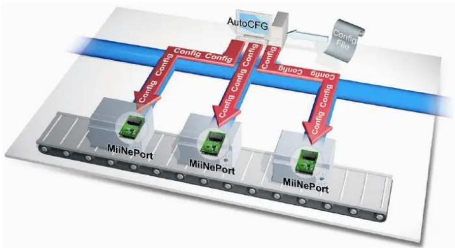
AutoCFG (Auto Configuration) saves time and effort when setting up the MiiNePort E2/E3 one by one during the device production process.
flowchart
graph TD
    A["AutoCFG"] -->|Config Config| B["MiiNePort"]
    A -->|Config Config| C["MiiNePort"]
    A -->|Config Config| D["MiiNePort"]
    B -->|Config Config| E["MiiNePort"]
    C -->|Config Config| F["MiiNePort"]
    D -->|Config Config| G["MiiNePort"]
    E --> H["Config Config"]
    F --> I["Config Config"]
    G --> J["Config Config"]
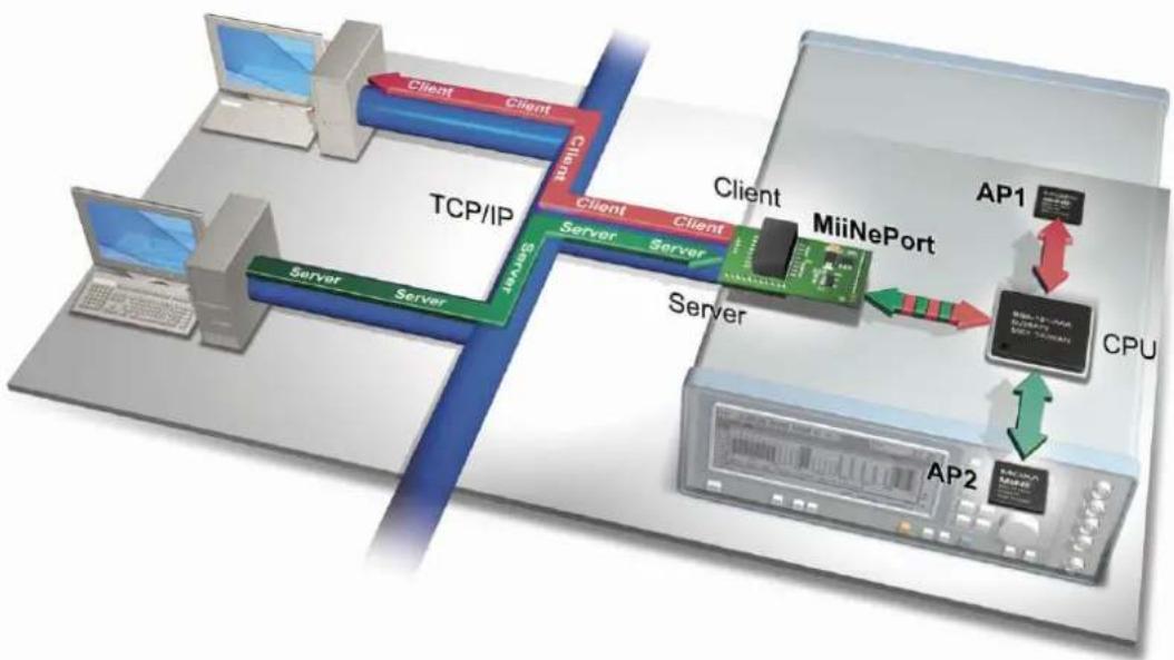
MCSC (Multiple Channel Serial Communication) provides dual connections and dual channels so your device can act as a server and client at the same time.
flowchart
graph TD
    subgraph TCP/IP
        A["Client"] --> B["Server"]
        C["Client"] --> D["Server"]
        E["Client"] --> F["Server"]
        G["Client"] --> H["Server"]
        I["Client"] --> J["Server"]
        K["Client"] --> L["Server"]
        M["Client"] --> N["Server"]
        O["Client"] --> P["Server"]
        Q["Client"] --> R["Server"]
        S["Client"] --> T["Server"]
        U["Client"] --> V["Server"]
        W["Client"] --> X["Server"]
        Y["Client"] --> Z["Server"]
        AA["Client"] --> AB["Server"]
        AC["Client"] --> AD["Server"]
        AE["Client"] --> AF["Server"]
        AG["Client"] --> AH["Server"]
        AI["Client"] --> AJ["Server"]
        AK["Client"] --> AL["Server"]
        AM["Client"] --> AN["Server"]
        AO["Client"] --> AP["Server"]
        AQ["Client"] --> AR["Server"]
        AS["Client"] --> AT["Server"]
        AU["Client"] --> AV["Server"]
        AW["Client"] --> AX["Server"]
        AY["Client"] --> AZ["Server"]
        BA["Client"] --> BB["Server"]
        BC["Client"] --> BD["Server"]
        BE["Client"] --> BF["Server"]
        BG["Client"] --> BH["Server"]
        BI["MiiNePort"] --> BJ["Server"]
    end
    subgraph CPU
        BK["AP1"] --> BL["MiiNePort"]
        BL --> BM["CPU"]
        BN["AP2"] --> BO["MiiNePort"]
        BP["AP2"] --> BQ["MiiNePort"]
    end
    style TCP/IP fill:#f9f,stroke:#333
    style CPU fill:#ccf,stroke:#333
    style CPU fill:#cfc,stroke:#333
    style CPU fill:#fcc,stroke:#333
    style TCP/IP fill:#ffc,stroke:#333
    style CPU fill:#fcc,stroke:#333
    style TCP/IP fill:#ffc,stroke:#333
    style CPU fill:#fcc,stroke:#333
    style TCP/IP fill:#ffc,stroke:#333
    style CPU fill:#fcc,stroke:#333
    style TCP/IP fill:#ffc,stroke:#333
    style TCP/IP fill:#fcc,stroke:#333
    style TCP/IP fill:#ffc,stroke:#333
    style TCP/IP fill:#fcc,stroke:#333
    style TCP/IP fill:#ffc,stroke:#333
    style TCP/IP fill:#fcc,stroke:#333
    style TCP/IP fill:#ffc,stroke:#333
    style TCP/IP fill:#fcc,stroke:#333
    style TCP/IP fill:none fill:#fff,stroke:#000
    style TCP/IP fill:none fill:none
    style TCP/IP fill:none fill:none
    style TCP/IP fill:none fill:none
    style TCP/IP fill:none fill:none
    style TCP/IP fill:none fill:none
    style TCP/IP fill:none fill:none
    style TCP/IP fill:none fill:none
    style TCP/IP fill:none fill:none
    style TCP/IP fill:none fill:none
    style TCP/IP fill:none fill:none
    style TCP/IP fill:none fill:none
    style TCP/IP fill:none fill:none
Product Specifications
Form Factor
Type:
MiiNePort E2: Drop-in module
MiiNePort E3: Pin header
Dimensions:
MiiNePort E2: 29 x 17 x 12.6 mm (1.14 x 0.67 x 0.50 in)
MiiNePort E3: 35 x 52.5 x 18 mm (1.37 x 2.07 x 0.71 in)
Weight:
MiiNePort E2: 5 g
MiiNePort E3: 12 g
System Information
CPU: 32-bit ARM Core
RAM: 4 MB built in
Flash: 2 MB built in
Ethernet Interface
Number of Ports: 1
Speed: 10/100 Mbps, auto MDI/MDIX
Serial Interface
Number of Ports: 1
Transmission Format: Standard TTL
Serial Communication Parameters
Data Bits: 5, 6, 7, 8
Stop Bits: 1, 1.5, 2
Parity: None, Even, Odd, Space, Mark
Flow Control: RTS/CTS, DTR/DSR, XON/XOFF
Baudrate:
MiiNePort E2/E3: 50 bps to 230.4 Kbps (suports non-standard baudrates)
MiiNePort E2-H/E3-H: 50 bps to 921.6 Kbps (supports non-standard baudrates)
Serial Signals
TTL: TxD, RxD, RTS, CTS, DTR, DSR, DCD, RST (reset circuit), GND
Digital I/O Pins
GPIO: 4 programmable I/O pins
Software
Network Protocols: ICMP, ARP, IP, TCP, UDP, DHCP, HTTP, SNMP V1, SMTP, TFTP, Auto IP, Telnet, BOOTP
Configuration Options: Web Console, Serial Console (Serial Command Mode), Telnet Console, Windows Utility
Windows Real COM Drivers: Windows 95/98/ME/NT/2000, Windows XP/2003/Vista/2008/7/8/8.1 x86/x64, Embedded CE 5.0/6.0, XP Embedded
Fixed TTY Drivers: SCO Unix, SCO OpenServer, UnixWare 7, SVR 4.2, QNX 4.25, QNX 6, Solaris 10, FreeBSD, AIX 5.x
Linux Real TTY Drivers: Linux kernel 2.4.x, 2.6.x, 3.x
Operation Modes: Real COM, TCP Server, TCP Client, UDP, Ethernet Modem, RFC2217, MCSC (MiiNePort E2 only)
Environmental Limits
Operating Temperature:
Standard Models: 0 to 55°C (32 to 131°F)
Wide Temp. Models: -40 to 85°C (-40 to 185°F)
Operating Humidity: 5 to 95% RH
Storage Temperature: -40 to 85°C (-40 to 185°F)
Power Requirements
Input Voltage: 3.3 or 5 VDC (± 5%)
Power Consumption:
MiiNePort E2: 140 mA @ 3.3 VDC max., 92 mA @ 5 VDC input max.
MiiNePort E3: 157 mA @ 3.3 VDC max., 119 mA @ 5 VDC input max.
Regulatory Approvals
FCC: Part 15 Class B
EMS: EN55022, EN55024, EN61000-3-2, EN61000-3-3, IEC61000-4-2, IEC61000-4-3, IEC61000-4-4, IEC61000-4-5, IEC61000-4-6, IEC61000-4-8, IEC61000-4-11
Shock: 500 g's for non-operational shock
Vibration: 20 g's for non-operational vibration
Warranty
Warranty Period: 5 years
Details: See www.moxa.com/warranty
Module Dimensions
MiiNePort E2
units: mm (in)
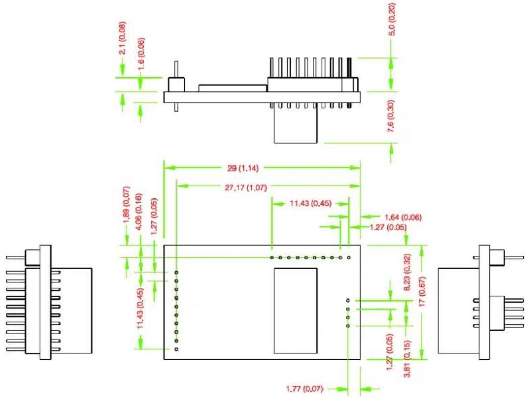
MiiNePort E3
units: mm (in)
![35 mm [1.38 in] 22.86 mm [0.9 in] 26 mm [1.02 in] 6.08 mm [0.24 in] 4.5 mm [0.18 in] 3.5 mm [0.14 in] 30.08 mm [1.18 in] 43 mm [1.69 in] 7.62 mm [0.3 in] L+ L1 R+ R2 2 16.25 mm [0.64 in] 3.06 mm [0.12 in] 2.54 mm [0.1 in] 9.27 mm [0.36 in] 50 mm [1.97 in] 52.5 mm [2.07 in]](/content/2026/05/1143673/images/1132156471470847e783791323fd4e6e7705bf47e28540a8e46dff86b2c5b53a.jpg)
Panel Layout and Pin Assignments
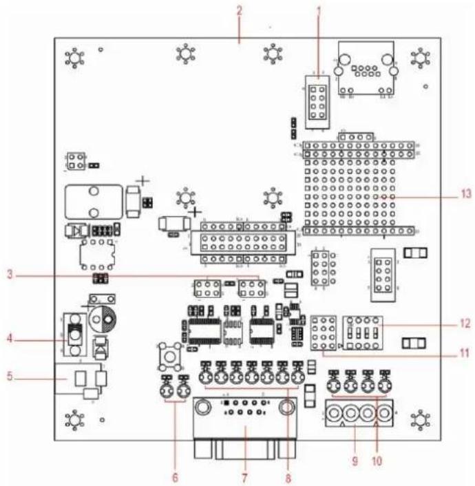
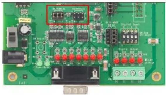
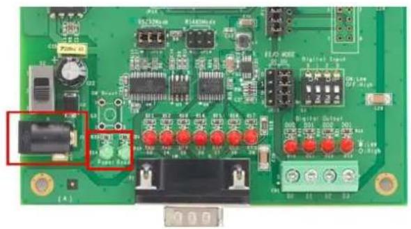
Evaluation Board Layout
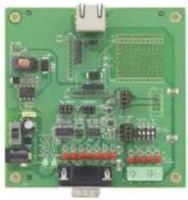
MiiNePort E2
| 1 | Ethernet RJ45 Connector |
| 2 | MiiNePort E2 Module Location |
| 3 | Serial Interface Jumper |
| 4 | Power Switch |
| 5 | Power Jack |
| 6 | Power & Ready LED |
| 7 | DB9 Male Connector |
| 8 | Serial Port Status LED |
| 9 | Digital IO Terminal Block |
| 10 | Digital Output LED |
| 11 | Digital Input/Output Mode |
| 12 | Digital Input Switch |
| 13 | Circuit Pad |
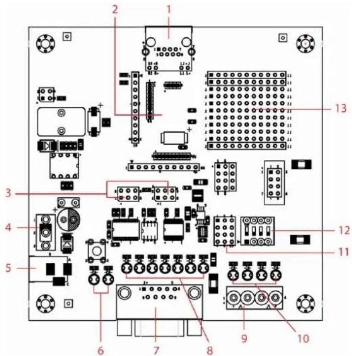
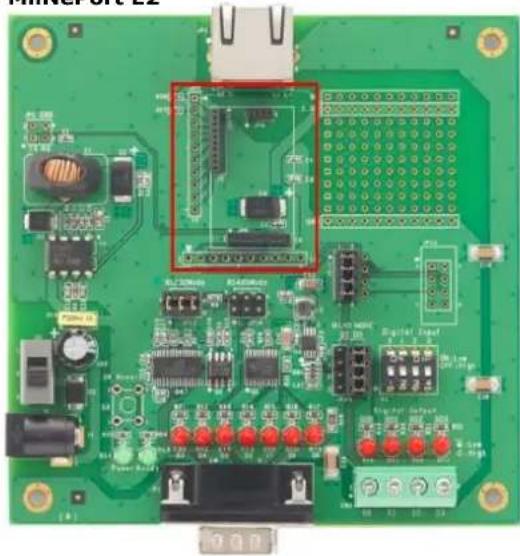
MiiNePort E3
| 1 | PoE Pin |
| 2 | MiiNePort E3 Module Location |
| 3 | Serial Interface Jumper |
| 4 | Power Switch |
| 5 | Power Jack |
| 6 | Power & Ready LED |
| 7 | DB9 Male Connector |
| 8 | Serial Port Status LED |
| 9 | Digital IO Terminal Block |
| 10 | Digital Output LED |
| 11 | Digital Input/Output Mode |
| 12 | Digital Input Switch |
| 13 | Circuit Pad |
Pin Assignments
MiiNePort E2 Module Pin Assignment
Bottom Panel of the MiiNePort E2 Module
| JP1 | ||
| Pin | Signal Name | Function |
| 1 | Ethernet Tx+ | Ethernet Transmit Data+ |
| 2 | Ethernet Tx- | Ethernet Transmit Data- |
| 3 | Ethernet Rx+ | Ethernet Receive Data+ |
| 4 | Ethernet Rx- | Ethernet Receive Data- |
| JP2 | ||
| Pin | Signal Name | Function |
| 1 | 100M LED | Ethernet 100M LED |
| 2 | 10M LED | Ethernet 10M LED |
| 3 | LRXD | Receive Serial Data |
| 4 | LTXD | Transmit Serial Data |
| 5 | LDCD | Data Carrier Detect |
| 6 | RS485_EN | RS-485 Enable |
| 7 | LRTS | Request To Send |
| 8 | LDTR | Data Terminal Ready |
| 9 | LDSR | Data Set Ready |
| 10 | LCTS | Clear To Send |
| JP3 | ||
| Pin | Signal Name | Function |
| 1 | DIO0 | Programmable Input/Output |
| 2 | DIO2 | Programmable Input/Output |
| 3 | DIO3 | Programmable Input/Output |
| 4 | DIO1 | Programmable Input/Output |
| 5 | Reserved | N/A |
| 6 | Reserved | N/A |
| 7 | SW Reset | Reset To Factory Default |
| 8 | GND | Circuit Ground |
| 9 | Ready LED | System is Ready LED |
| 10 | VCC | Power Supply |
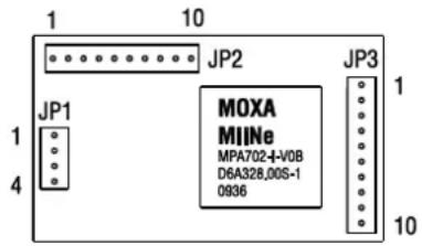
MiiNePort E3 Module Pin Assignment
| Ethernet Pins (JP2) | ||
| Pin | Signal Name | Function |
| 1 | Reserve | N/A |
| 2 | Reserve | N/A |
| 3 | Reserve | N/A |
| 4 | Reserve | N/A |
| 5 | PoE signal pair 1 | PoE power from Tx signal |
| 6 | PoE spare pair 1 | PoE power from RJ45 4, 5 pin |
| 7 | PoE signal pair 2 | PoE power from Rx signal |
| 8 | PoE spare pair 2 | PoE power from RJ45 7, 8 pin |
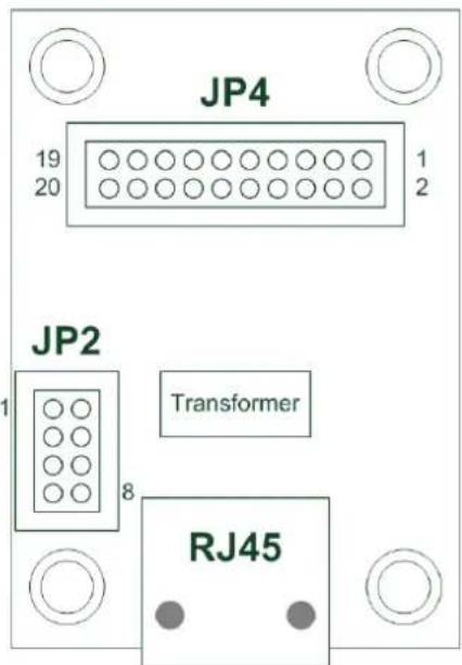
| Serial Pins and Power Pins (JP4) | ||
| Pin | Signal Name | Function |
| 1 | Serial Rx | Receive Serial Data |
| 2 | Ready LED | System to Ready LED |
| 3 | Serial Tx | Transmit Serial Data |
| 4 | GPIO | Programmable I/O |
| 5 | DCD | Receive Line Signal Detector |
| 6 | GPIO | Programmable I/O |
| 7 | RS485_EN0 | RS-485 Enabled |
| 8 | GPIO | Programmable I/O |
| 9 | RTS | Request to Send |
| 10 | GPIO | Programmable I/O |
| 11 | DTR | Data Terminal Ready |
| 12 | Reserve | N/A |
| 13 | DSR | Data Set Ready |
| 14 | Reserve | N/A |
| 15 | CTS | Clear to Send |
| 16 | SW_Reset | Reset to Factory Default |
| 17 | Reserve | N/A |
| 18 | Reserve | N/A |
| 19 | GND | Circuit Ground |
| 20 | VCC | Power Supply |
Evaluation Board Ethernet Port Pin Assignment
RJ45
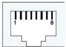
| Pin | Signal |
| 1 | Tx+ |
| 2 | Tx- |
| 3 | Rx+ |
| 6 | Rx- |
Evaluation Board Serial Port Pin Assignment
DB9 Male
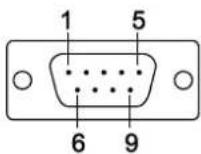
| Pin | RS-232 | RS-485-2W |
| 1 | DCD | - |
| 2 | RxD | - |
| 3 | TxD | D+ |
| 4 | DTR | D- |
| 5 | GND | GND |
| 6 | DSR | - |
| 7 | RTS | - |
| 8 | CTS | - |
| 9 | - | - |
LED Indicators
MiiNePort Evaluation Board
natural_image
Green printed circuit board with various electronic components and connectors (no visible text or symbols)| LED Name | Color | Description |
| Power | Off | 1. Power is off2. Power error condition exists3. System error |
| Green, Steady On | Indicates that the power is on. | |
| Ready | Green, Blinking every 1 sec. | 1. The device server has been located by NPort search utility location function.2. Auto Config complete. |
| Green, Blinking every 0.5 sec. | Indicates a LAN IP conflict, or DHCP or BOOTP server did not respond properly. | |
| TXD / LED D3 | Red | Indicates that TXD has a signal. |
| RXD / LED D4 | Red | Indicates that RXD has a signal. |
| DTR / LED D5 | Red | Indicates that DTR has a signal. |
| CTS / LED D6 | Red | Indicates that CTS has a signal. |
| DSR / LED D7 | Red | Indicates that DSR has a signal. |
| DCD / LED D8 | Red | Indicates that DCD has a signal. |
| RTS / LED D9 | Red | Indicates that RTS has a signal. |
| DO0 / LED D10 | Red | Indicates that DO0 is in "low" (0) status. |
| DO1 / LED D11 | Red | Indicates that DO1 is in "low" (0) status. |
| DO2 / LED D12 | Red | Indicates that DO2 is in "low" (0) status. |
| DO3 / LED D13 | Red | Indicates that DO3 is in "low" (0) status. |
This chapter includes information about how to install MiiNePort Series modules for development and testing.
The following topics are covered in this chapter:
□ Wiring Precautions
☐ Installing the MiiNePort module onto the MiiNePort Evaluation Board
☐ Selecting the Serial Interface
□ Connecting the Power
☐ Connecting to the Network
☐ Connecting to a Serial Device
☐ Digital I/O Channel Settings
☐ Schematic Design Guide
Wiring Precautions
This section describes some important safety precautions that you should pay attention to before proceeding with any installation.

ATTENTION
Be sure to disconnect the power cord before installing or wiring the evaluation board.

ATTENTION
Determine the maximum possible current in each power wire and common wire. Observe all electrical codes dictating the maximum current allowable for each wire size. If the current goes above the maximum ratings, the wiring could overheat, causing serious damage to your equipment.

ATTENTION
Take care when handling the evaluation board. When plugged in, the evaluation board's internal components generate heat, and consequently the board may feel hot to the touch.
You should also pay attention to the following:
- Do not run signal or communication wiring and power wiring in the same wire conduit. To avoid interference, wires with different signal characteristics should be routed separately. Separate paths should be used to route wiring for power and devices. You can use the type of signal transmitted through a wire to determine which wires should be kept separate. The rule of thumb is that wires sharing similar electrical characteristics may be bundled together.
- Keep input wiring and output wiring separate.
- If power wiring and device wiring paths must cross paths, make sure the wires are perpendicular at the intersection point.
- All wiring should be clearly labeled.
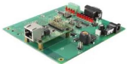
Installing the MiiNePort module onto the MiiNePort Evaluation Board
Before using the MiiNePort evaluation board with the module, be sure to disconnect the power supply, network, and serial device. A profile of the MiiNePort is shown in the center of the evaluation board near the top. The profile indicates where you should install the module onto the evaluation board (refer to the figure at the right). When attaching the module to the evaluation board, make sure the module is securely installed on the evaluation board. After the module is installed, connect the power supply, network, and serial device to the evaluation board.
natural_image
Green printed circuit board with various electronic components and connectors (no visible text or symbols)MiiNePort E2
natural_image
Green printed circuit board with various electronic components and connectors (no readable text or symbols)Selecting the Serial Interface
The MiiNePort module uses a standard TTL serial signal input. However, to make evaluation more convenient, the evaluation board has built-in RS-232 and RS-485 interfaces. Use a 6-pin jumper to select which serial interface is active.
• RS-232: short the 6-pin jumper to JP13
• RS-485: short the 6-pin jumper to JP14
natural_image
Green printed circuit board with various electronic components and connectors (no readable text or symbols)Connecting the Power
Connect the 12-48 VDC power line with the evaluation board's power jack. If the power is properly supplied, the power LED on the evaluation board (D14) will show a solid green color until the system is ready. When the system is ready, the ready LED on the module will show a solid green color.
natural_image
Green printed circuit board with various electronic components and connectors (no readable text or symbols)Connecting to the Network
To connect to the network for testing and development purposes, plug the Ethernet cable into the RJ45 jack on the evaluation board. If the cable is properly connected, the LED will indicate a valid connection to the Ethernet as follows:
| LED | Color | Meaning |
| Left | Amber | 10BASE-T Link Activity(does not blink when not transmitting; blinks when transmitting) |
| Right | Green | 100BASE-TX Link Activity(does not blink when not transmitting; blinks when transmitting) |
When using a private IP address (192.168.xxx.xxx), be sure the netmask and IP address are configured to allow hosts on the private network to access the module. Note that by default, the module is configured to use a private IP address.
Connecting to a Serial Device
To connect to a serial device for testing and development purposes, the module should be installed on the evaluation board. Be sure to select the serial interface you would like to use before you connect the evaluation board to the serial device. (Refer to the Selecting the Serial Interface section above when you are using jumper blocks to select the serial interface on the evaluation board.) The module's serial signals are routed to and from the RS-232 or RS-485 COM port on the evaluation board. Use a serial data cable to connect the serial device to the COM port on the evaluation board.
Digital I/O Channel Settings
Each module has 4 digital I/O (DIO) channels. (Refer to the Pin Assignment section in Chapter 1 for the module's configurable DIO pin descriptions. Refer to the Evaluation Board Layout section in Chapter 1 to select corresponding settings on the evaluation board.) All 4 DIO channels can be configured by software. A DI channel is a channel that operates in digital input mode; a DO channel is a channel that operates in digital output mode. You can use the evaluation board's Digital Output LEDs and Digital Input DIP switches as the digital input and output devices, or you can connect digital input/output devices to the DIO Terminal Block.

ATTENTION
When using a digital input device connected to the DIO Terminal Block, the corresponding Digital Input DIP switch must be set to "OFF" or "High". Setting the DIP switch to "ON" or "Low" will interfere with the signal from your digital input device.
For channels in digital output mode, the "Low" versus "High" setting is controlled from the web console. When using a Digital Output LED as your output device, the LED will be on to indicate that the status is "Low" and the LED will be off to indicate that the status is "High".
Schematic Design Guide
For guidance and suggestions on integrating your device's hardware with the MiiNePort, refer to the MiiNePort Schematic Design Guide in the Document and Software CD.
The MiiNePort modules support operation modes for COM mapping and TCP/IP. After choosing the proper operation mode for your application, refer to subsequent chapters for configuration details.
The following topics are covered in this chapter:
Overview
Real COM Mode
□ TCP Server Mode
TCP Client Mode
□ RFC2217 Mode
□ UDP Mode
☐ Ethernet Modem Mode
□ MCSC Mode
Overview
The MiiNePort acts as a bridge for connecting serial devices to Ethernet networks. After choosing the best operation mode for your application, you can use your computer to access, manage, and configure your serial devices from anywhere in the world over the Internet.
Traditional SCADA and data collection systems rely on serial ports (RS-232/422/485) to collect data from various kinds of instruments. Since MiiNePort modules convert between serial and Ethernet signals, you will be able to access your SCADA and data collection system from hosts connected to a standard TCP/IP network, regardless of whether the devices are used locally or at a remote site.
The MiiNePort modules support Real COM mode and six different socket modes—TCP Server, TCP Client, Ethernet Modem, RFC2217, UDP, and MCSC. The main difference between the TCP and UDP protocols is that TCP guarantees delivery of data by requiring the recipient to send an acknowledgement to the sender. UDP does not require this kind of verification, and consequently UDP is faster than TCP. UDP also allows multicasting of data to groups of IP addresses.
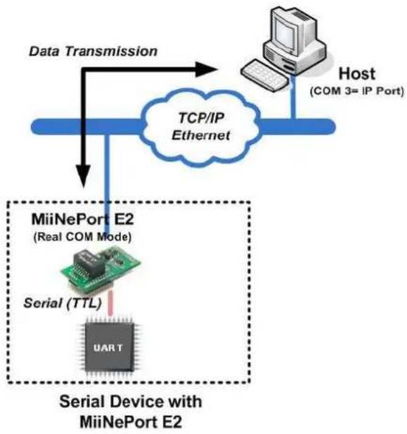
Real COM Mode
Real COM mode allows users to continue using software that was written for pure serial communications applications. Each module comes equipped with COM drivers for Windows systems (95 and above). The module's serial port is mapped by the driver to an IP address and port number. The driver intercepts data sent to the host's COM port, packs it into a TCP/IP packet, and then redirects it through the host's Ethernet card. At the other end of the connection, the module accepts the Ethernet frame, unpacks the TCP/IP packet, and then transparently sends the data to the attached serial device. In other words, a PC host can treat networked devices as though the devices were connected directly to the PC.
flowchart
graph TD
    A["Host (COM 3= IP Port)"] --> B["TCP/IP Ethernet"]
    B --> C["MiiNePort E2 (Real COM Mode)"]
    C --> D["Serial Device with MiiNePort E2"]
    D --> E["Data Transmission"]
    E --> B
    style C stroke-dasharray: 5 5
    style D stroke-dasharray: 5 5
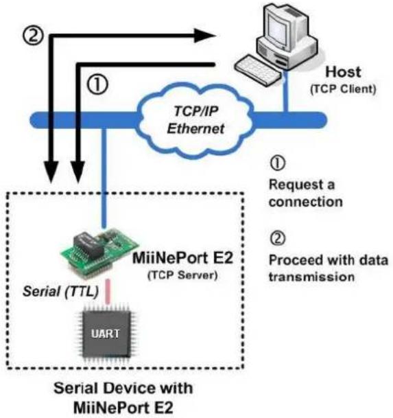
TCP Server Mode
In TCP Server mode, the module is assigned a unique IP address and port number on the TCP/IP network. The module waits passively to be contacted by the host computer, allowing the host computer to establish a connection with and obtain data from the serial device. TCP Server mode supports up to 4 simultaneous connections so that multiple hosts can collect data from the same serial device—at the same time. Data transmission proceeds as follows:
-
The host connects to the module configured for TCP Server mode.
-
Once the connection is established, data can be transmitted in both directions—from the host to the module, and from the module to the host.
flowchart
graph TD
    A["Host (TCP Client)"] --> B["TCP/IP Ethernet"]
    B --> C["MiiNePort E2 (TCP Server)"]
    C --> D["Serial Device with MiiNePort E2"]
    D --> E["Serial (TTL)"]
    E --> F["UART"]
    style A fill:#f9f,stroke:#333
    style B fill:#ccf,stroke:#333
    style C fill:#cfc,stroke:#333
    style D fill:#fcc,stroke:#333
    style E fill:#cff,stroke:#333
    style F fill:#ffc,stroke:#333
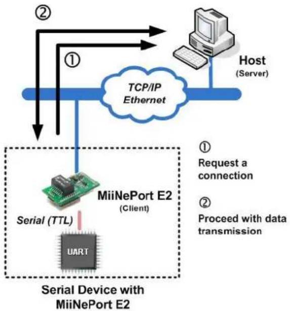
TCP Client Mode
In TCP Client mode, the module can actively establish a TCP connection to a pre-defined host computer when serial data arrives. After the data has been transferred, the module can be automatically disconnected from the host computer by using the "TCP alive check time" or "Inactivity time" settings. Refer to subsequent chapters for details. Data transmission proceeds as follows:
- The module actively establishes a connection based on the conditions set in the firmware. You may let the module connect to a remote host on startup, or connect later when data from the serial device arrives.
- Once the connection is established, data can be transmitted in both directions—from the host to the module, and from the module to the host.
flowchart
graph TD
    A["Host (Server)"] --> B["TCP/IP Ethernet"]
    B --> C["MiiNePort E2 (Client)"]
    C --> D["Serial Device with MiiNePort E2"]
    D --> E["Serial (TTL)"]
    E --> F["UART"]
    style A fill:#f9f,stroke:#333
    style B fill:#ccf,stroke:#333
    style C fill:#cfc,stroke:#333
    style D fill:#fcc,stroke:#333
    style E fill:#cff,stroke:#333
    style F fill:#ffc,stroke:#333
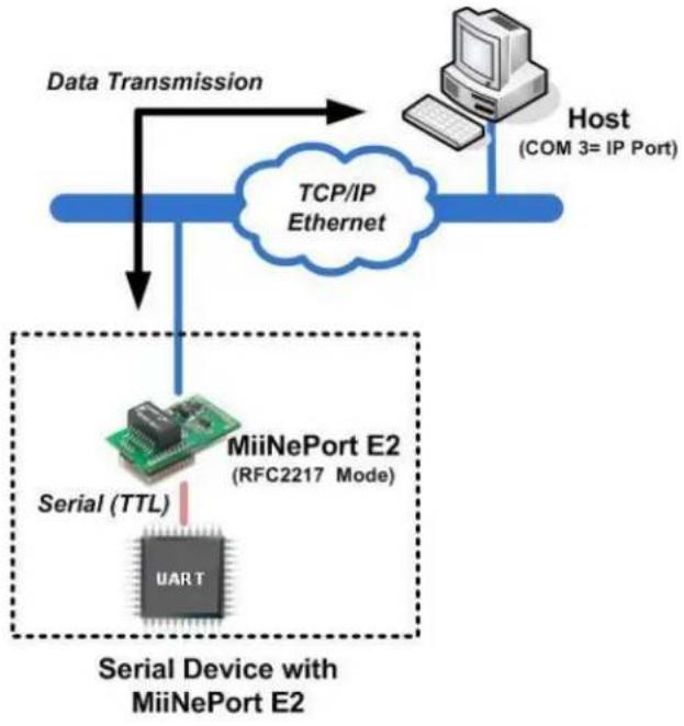
RFC2217 Mode
RFC2217 is an industrial public protocol for sharing serial devices over TCP/IP Ethernet networks. RFC2217 is similar to Moxa's proprietary Real COM mode in that it allows users to continue using software that was written for pure serial communications applications. Each module comes equipped with COM drivers for Windows systems (95 and above). The module's serial port is mapped by the driver to an IP address and port number. The driver intercepts data sent to the host's COM port, packs it into a TCP/IP packet, and then redirects it through the host's Ethernet card.
flowchart
graph TD
    A["Host (COM 3= IP Port)"] --> B["TCP/IP Ethernet"]
    B --> C["MiiNePort E2 (RFC2217 Mode)"]
    C --> D["Serial Device with MiiNePort E2"]
    D --> E["Data Transmission"]
    E --> F["Serial (TTL)"]
    F --> G["UART"]
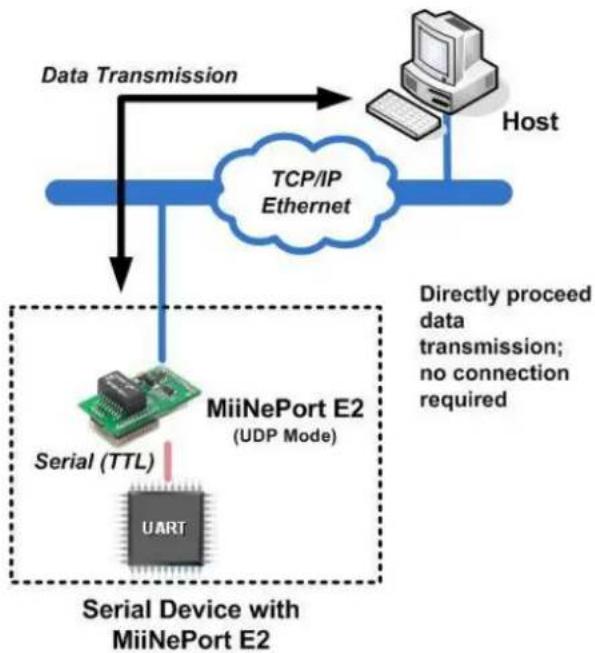
UDP Mode
UDP is similar to TCP but is faster and more efficient. Although data can be broadcast to or received from multiple network hosts, UDP does not support data verification, and consequently is not suitable for applications for which data integrity is critical. UDP would, however, be suitable for message display applications.
flowchart
graph TD
    Host["Host"] -->|Data Transmission| MiiNePortE2["MiiNePort E2 (UDP Mode)"]
    MiiNePortE2 --> SerialDevice["Serial Device with MiiNePort E2"]
    SerialDevice --> MiiNePortE2
    MiiNePortE2 --> TCP/IP["Ethernet"]
    TCP/IP --> Host
    style MiiNePortE2 fill:#f9f9f9,stroke-dasharray: 5 5
    note right of MiiNePortE2: Directly proceed data transmission; no connection required

ATTENTION
The Real COM driver comes with NPort Windows Driver Manager, which is included on the CD-ROM shipped with the MiiNePort Starter kit.

ATTENTION
Real COM mode allows several hosts to simultaneously access to the MiiNePort module. The driver controls host access to attached serial devices by checking the host's IP address against the Accessible IP list. Use the Accessible IP table to restrict access to the module when a public IP address is required for your application.
Ethernet Modem Mode
Ethernet Modem Mode is designed for use with legacy operating systems, such as MS-DOS, that do not support TCP/IP Ethernet. By connecting the MiiNePort evaluation board's serial ports to an MS-DOS computer's serial port, it is possible to use legacy software originally designed to transmit data via modem, but now transmit the data over the Ethernet.
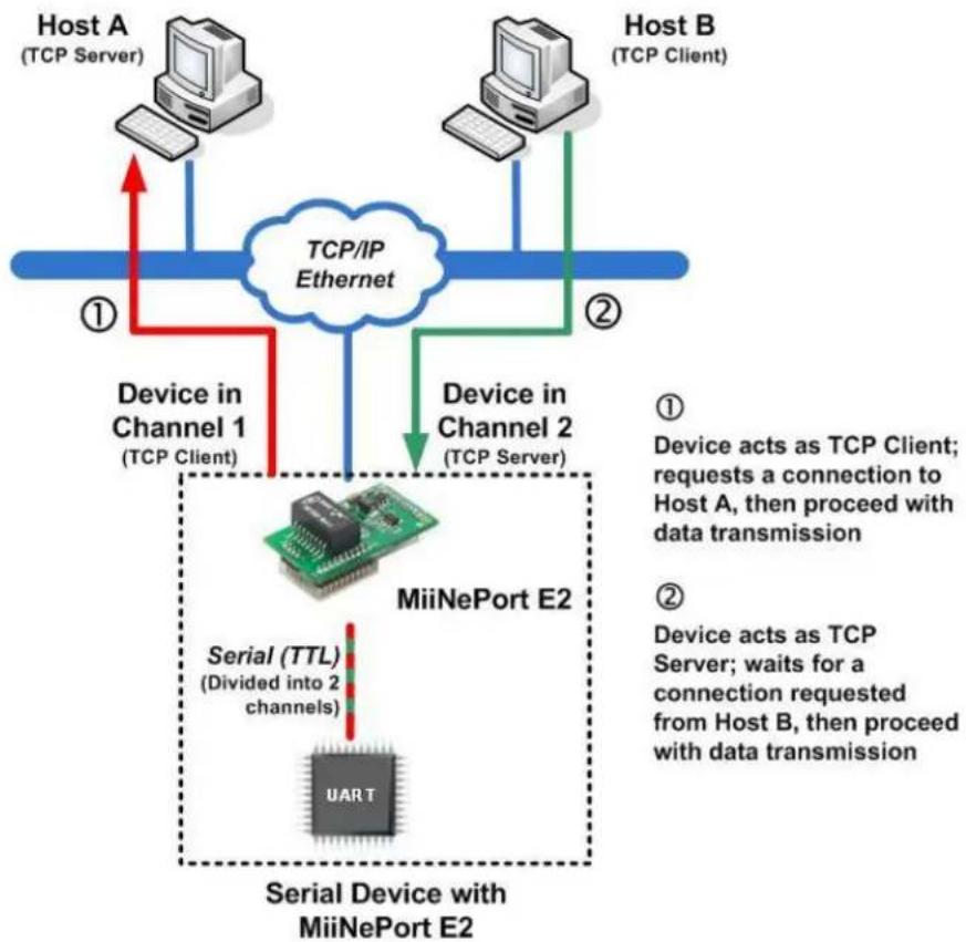
MCSC Mode (MiiNePort E2 Only)
MCSC (Multiple Channel Serial Communication) was developed for multiple serial-to-Ethernet applications that use only one serial port. For example, if you need your device to act as a TCP Server and TCP Client at the same time (as illustrated below), you can use MCSC.
flowchart
graph TD
    A["Host A (TCP Server)"] -->|① Device in Channel 1 (TCP Client)| B["TCP/IP Ethernet"]
    C["Host B (TCP Client)"] -->|② Device in Channel 2 (TCP Server)| B
    B --> D["MiiNePort E2"]
    D --> E["Serial Device with MiiNePort E2"]
    E --> F["Serial (TTL) (Divided into 2 channels)"]
    F --> G["UART"]
    style D fill:#f9f,stroke:#333
    style E fill:#ccf,stroke:#333
For details on MCSC's functionality and configuration, refer to Chapter 8: NetEZ Technologies' MCSC. MCSC is only supported on the MiiNePort E2.
The MiiNePort supports several tools for configuring the module. In this chapter we briefly describe the options available and appropriate situations for using those options.
The following topics are covered in this chapter:
□ Utility Console
□ Web Console
□ Telnet Console
☐ SCM (Serial Command Mode)
Utility Console
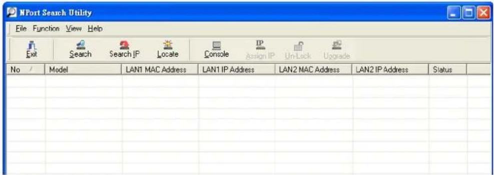
NPort Search Utility
You can find NPort Search Utility on the CD-ROM that came with your product. NPort Search Utility is designed for Windows and is mainly used to search for the MiiNePort modules and for assigning IP addresses. Refer to the Web Console for additional configuration information.
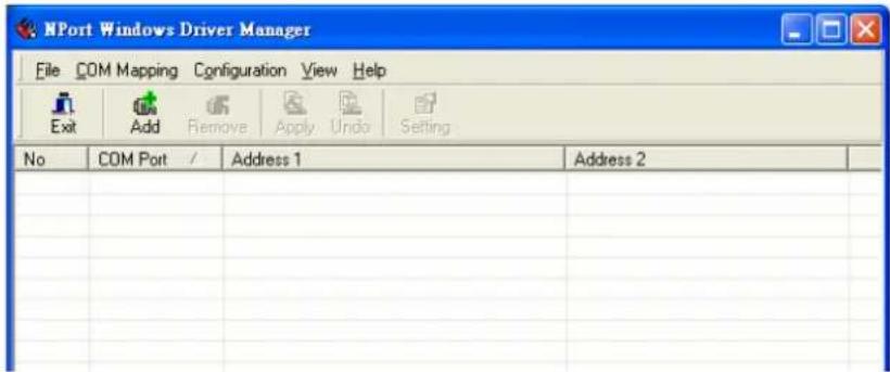
NPort Windows Driver Manager
NPort Windows Driver Manager is intended for use with Real COM mode. The software manages the installation of drivers that allow you to map unused COM ports on your PC to serial ports on the MiiNePort.
Refer to Chapter 6: Utility Console and Driver Installation for details on how to use NPort Search Utility and NPort Windows Driver Manager.
Web Console
After locating a MiiNePort with NPort Search Utility, you may configure the MiiNePort using a standard web browser. Refer to Chapter 7: Web Console Configuration for details on how to access and use the MiiNePort web console.
Telnet Console
Your MiiNePort can be configured over the network with Telnet, which requires that the module has a network connection and an IP address. We briefly discuss Telnet console configuration in Chapter 5: Initial IP Address Configuration. All Telnet console commands are introduced in Chapter 7: Web Console Configuration.
SCM (Serial Command Mode)
The MiiNePort's SCM (Serial Command Mode) allows the module's parameters to be retrieved and configured through the serial port. This is accomplished using specially parsed commands sent to the module through the serial port.
SCM is often used when your device has already been used in a real application and a configuration change, such as changing the device's IP address with the device's key pad, is required.
Refer to Chapter 7: Web Console Configuration for details on how to access and use the MiiNePort's SCM. Refer to Appendix A: Introduction to SCM (Serial Command Mode) for the SCM command set instructions.
When setting up your MiiNePort module for the first time, the first thing you should do is configure the IP address. This chapter introduces the methods that can be used to configure the module's IP address. For more details about network settings, refer to the Network Settings section in Chapter 7: Web Console Configuration.
The following topics are covered in this chapter:
☐ Static vs. Dynamic IP Address
□ Factory Default IP Address
□ ARP
Telnet Console
Static vs. Dynamic IP Address
You should first determine whether the module will be assigned a Static IP or Dynamic IP (either DHCP or BOOTP application).
- If the module is used in a Static IP environment, you need to configure the IP address directly.
- If the module is used in a Dynamic IP environment, you need to configure the module to obtain an IP address dynamically with DHCP, DHCP/BOOTP, BOOTP, or AUTOIP.

ATTENTION
Consult your network administrator on how to reserve a fixed IP address for the module in the MAC-IP mapping table when using a DHCP Server or BOOTP Server. For most applications, you should assign a fixed IP address to the module.
Factory Default IP Address
The MiiNePort module is configured with the following default private IP address:
192.168.127.254
IP addresses of the form 192.168.xxx.xxx are referred to as private IP addresses, since it is not possible to directly access a device configured with a private IP address from a public network. For example, you would not be able to ping such a device from an outside Internet connection. Applications that require sending data over a public network, such as the Internet, require setting up the server with a valid public IP address, which can be leased from a local ISP.
ARP
You can use the ARP (Address Resolution Protocol) command to set up the module's IP address. The ARP command tells your computer to associate the module's MAC address with the intended IP address. You must then use Telnet to access the module, at which point the module's IP address will be reconfigured.

ATTENTION
In order to use ARP, both your computer and the module must be connected to the same LAN. You may also use a cross-over Ethernet cable to connect the module directly to your computer's Ethernet port. Your module must be configured with the factory default IP address before executing the ARP command.
To configure the IP address using ARP, follow these instructions:
- Obtain a valid IP address for the module from your network administrator.
- Obtain the module's MAC address from the label on the module.
- Execute the arp -s command from your computer's MS-DOS prompt by typing:
arp -s
For example,
arp -s 192.168.200.100 00-90-E8-00-00-00
In this example, 192.168.200.100 is the new IP address and 00-90-E8-00-00-00 is the module's MAC address, as obtained in steps 1 and 2.
- Execute a special Telnet command by typing:
telnet
For example,
telnet 192.168.200.100 6000
After issuing this command, a Connect failed message will appear. After the module reboots, its IP address will be updated to the new address, and you can reconnect the module using the utility, web, or Telnet console to verify that the update was successful.
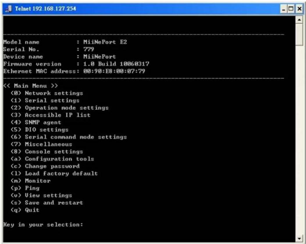
Telnet Console
Depending on how your computer and network are configured, you may find it convenient to use network access to set up your module's IP address. This can be done using Telnet, which requires that the module has a network connection and an IP address.
- From the Windows desktop, click Start and then select Run.
- Telnet to the module's current IP address. If this is the first time configuring the module, you will telnet to the default IP address by typing telnet 192.168.127.254 in the Open text box. Click OK to proceed.
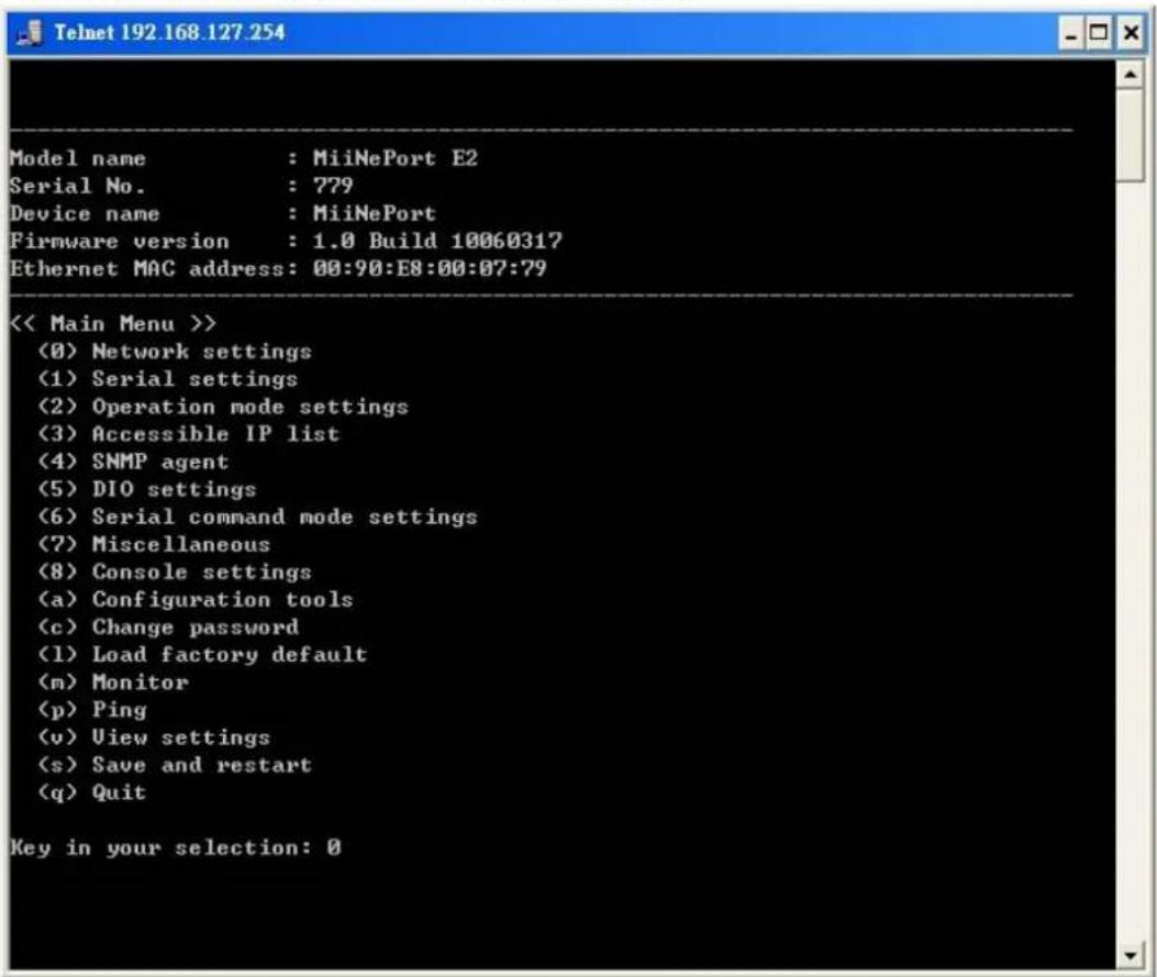
- Select Network settings by pressing 0 and then press Enter.
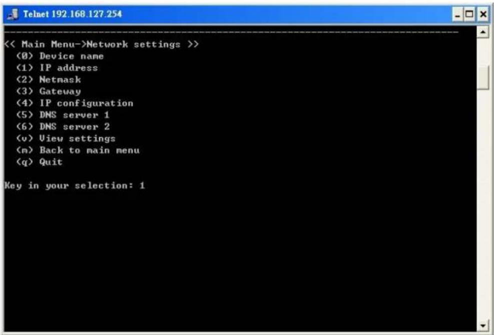
- Select IP address by pressing 1 and then press Enter.
- Use the Backspace key to erase the current IP address. Type in the new IP address and then press Enter.
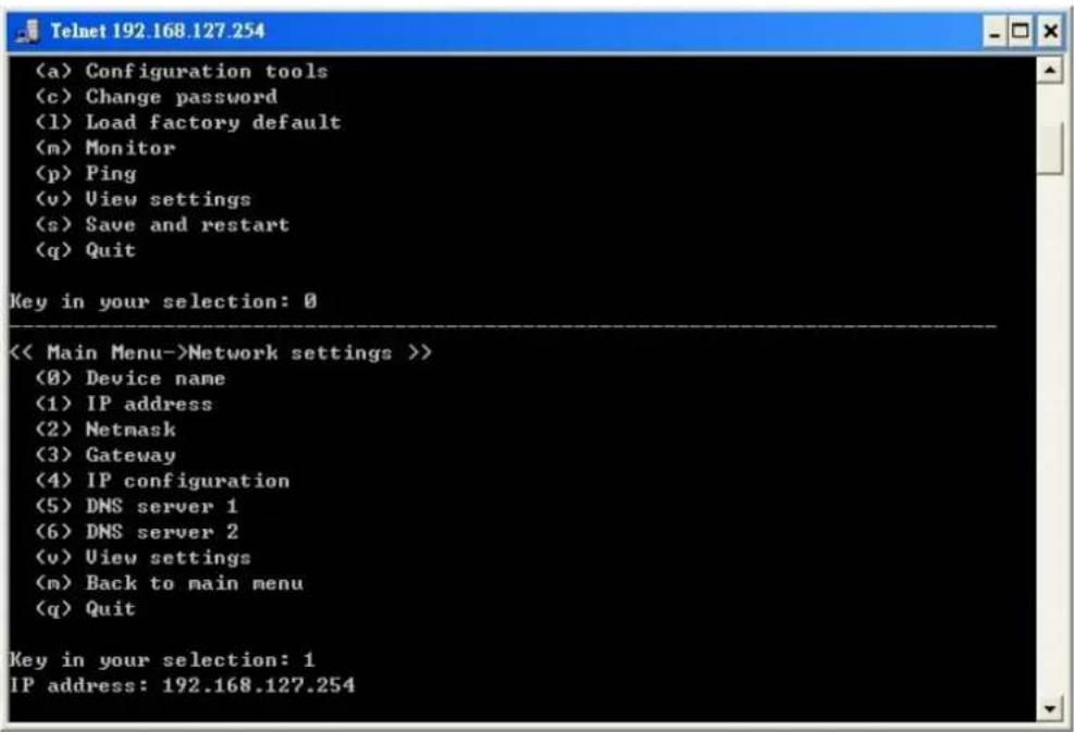
- Press any key to continue.
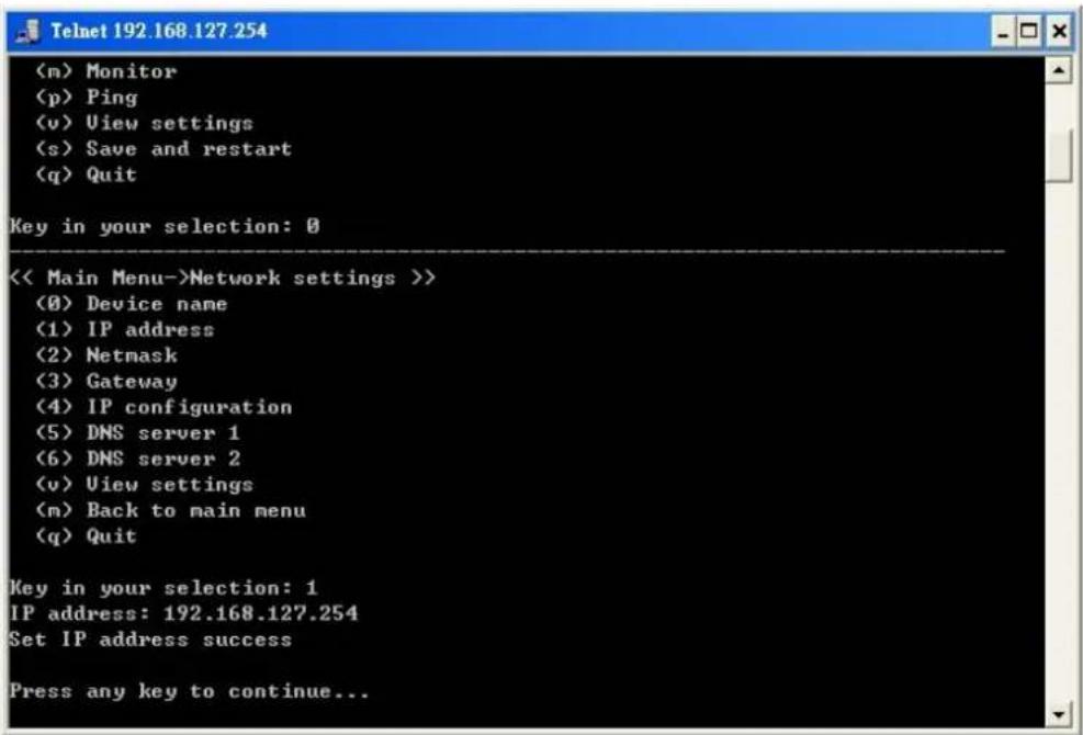
- Press M and then Enter to return to the main menu.
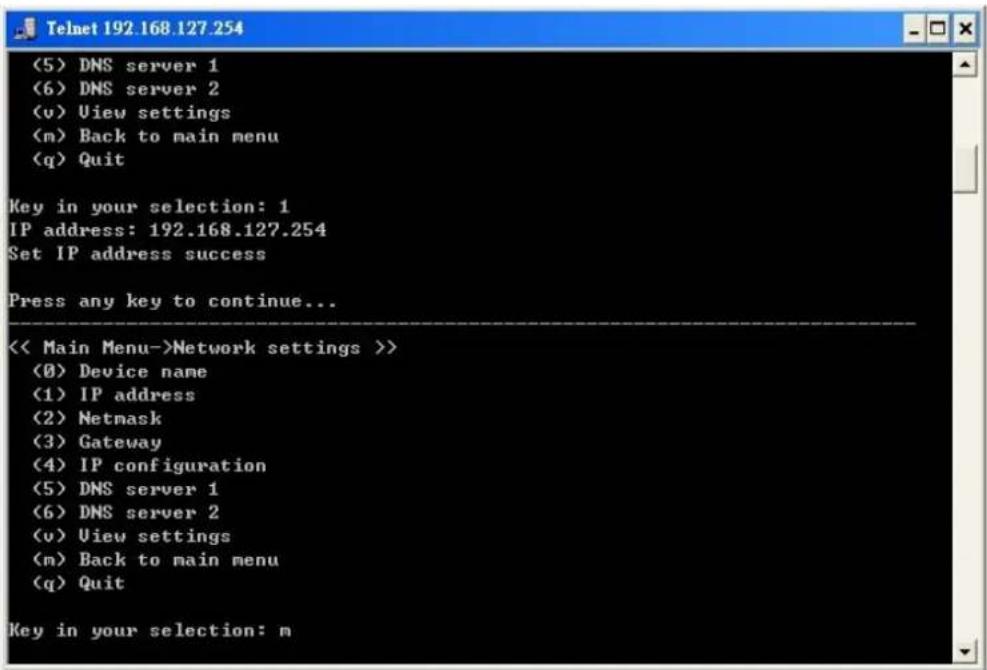
- Press S and then Enter to Save/Restart the system.
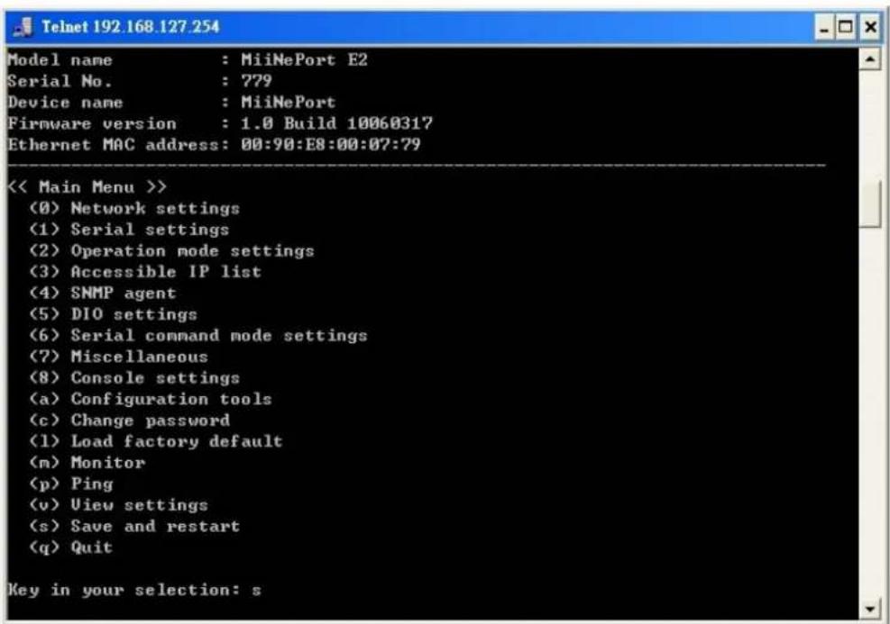
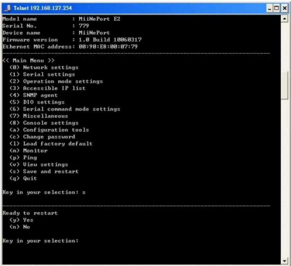
- Press Y and then Enter to save the new IP address and restart the module.
This chapter teaches you how to install the MiiNePort's utilities, use the utilities to perform simple configurations, and install the drivers.
The following topics are covered in this chapter:
□ NPort Search Utility
- Installing NPort Search Utility
- NPort Search Utility Configuration
□ NPort Windows Driver Manager
Installing NPort Windows Driver Manager
➢ Using NPort Windows Driver Manager
☐ The Linux Real TTY Driver
Mapping TTY Ports
➢ Removing Mapped TTY Ports
Removing Linux Driver Files
☐ The UNIX Fixed TTY Driver
Installing the UNIX Driver
➢ Configuring the UNIX Driver
NPort Search Utility
Installing NPort Search Utility
- Click the INSTALL UTILITY button in the MiiNePort Installation CD to install NPort Search Utility. Once the program starts running, click Yes to proceed.
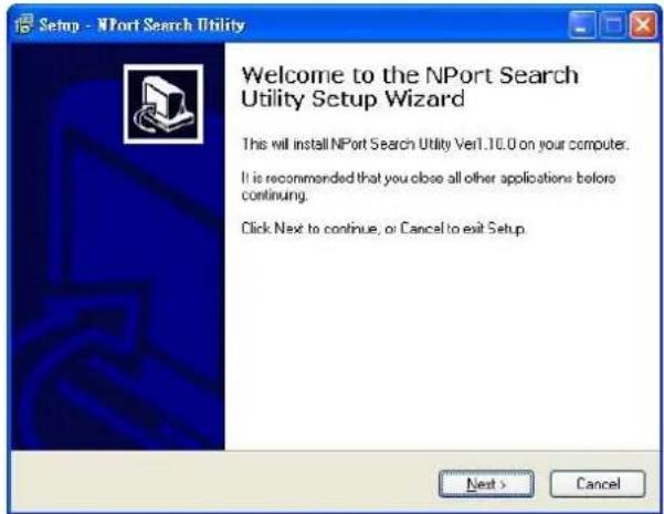
- Click Next when the Welcome screen opens to proceed with the installation.
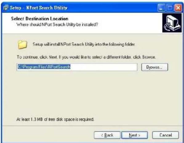
- Click Browse to select an alternate location and then click Next to install program files to directory displayed in the input box.
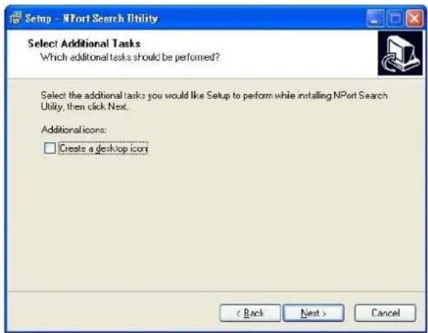
- Click Next to install the program's shortcuts in the appropriate Start Menu folder.
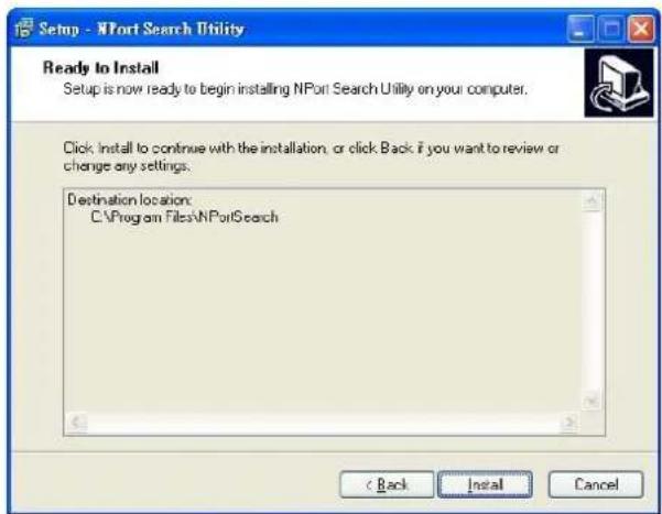
- The installer will display a summary of the installation options. Click Install to begin the installation. The setup window will report the progress of the installation. To change the installation settings, click Back and navigate to the previous screen.
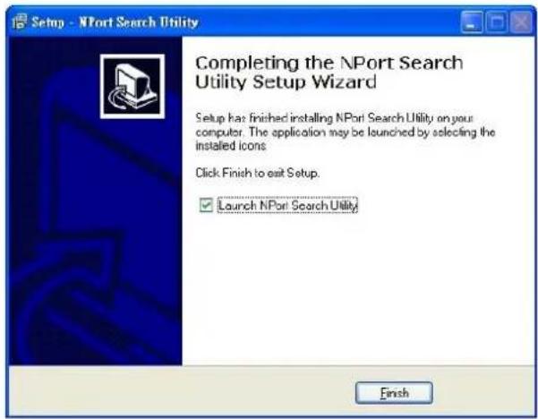
- Click Finish to complete the installation of NPort Search Utility.
NPort Search Utility Configuration
The Broadcast Search function is used to locate all MiiNePort modules that are connected to the same LAN as your computer. After locating a MiiNePort, you will be able to change its IP address. Since the Broadcast Search function searches by MAC address and not IP address, all MiiNePort modules connected to the LAN will be located, regardless of whether or not they are part of the same subnet as the host.
- Start the NPort Search Utility and then click the Search icon.
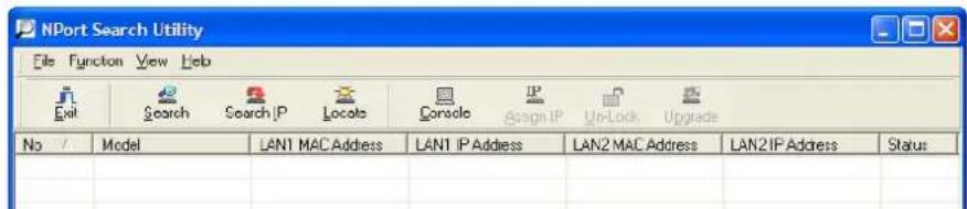
Note: Users running Windows Vista and Windows 7 will see a "User Account Control" popup and should allow the program.
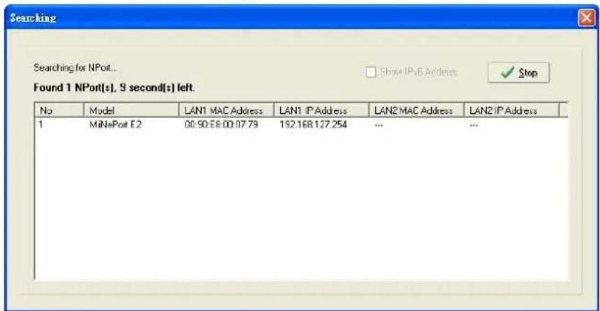
- The Searching window indicates the progress of the search.
- When the search is complete, all MiiNePort modules that were located will be displayed in the NPort Search Utility window.
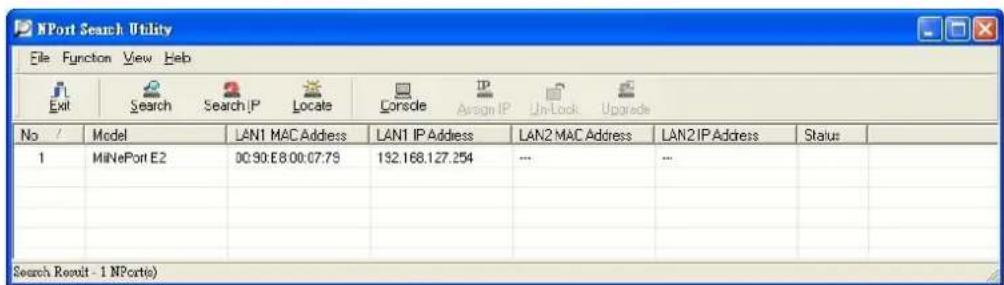
- To modify the configuration of the highlighted MiiNePort, click the Console icon to open the web console. This will take you to the web console, where you can make configuration changes. Refer to Chapter 7: Web Console Configuration for information on how to use the web console.

ATTENTION
If you are looking for information related to TCP Server, TCP Client, Ethernet Modem, RFC2217, or UDP modes, you can ignore the following Driver sections, including NPort Windows Driver Manager and Linux Real TTY Driver, and instead jump directly to Chapter 7: Web Console Configuration for additional settings.
NPort Windows Driver Manager
Installing NPort Windows Driver Manager
NPort Windows Driver Manager is intended for use with serial ports that are set to Real COM mode. The software manages the installation of drivers that allow you to map unused COM ports on your PC to your device through the MiiNePort's serial port. The driver screenshots below were captured in Windows XP/2003/Vista/2008/7 (x86/x64) When the drivers are installed and configured, devices that are embedded with the MiiNePort will be treated as if they are attached to your PC's own COM ports.
-
Click the INSTALL COM Driver button in the MiiNePort Installation CD to install the NPort Windows Driver. Once the installation program starts running, click Yes to proceed.
-
Click Next when the Welcome screen opens to proceed with the installation.

- Click Browse to select the destination directory and then click Next to install program files to the directory displayed in the input box.
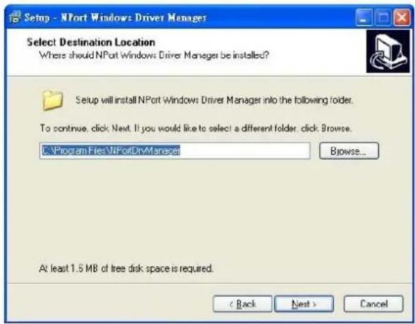
- Click Next to install the program's shortcuts in the appropriate Start Menu folder.
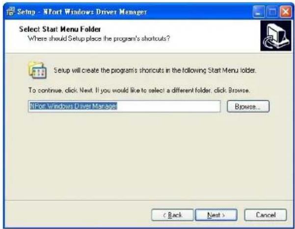
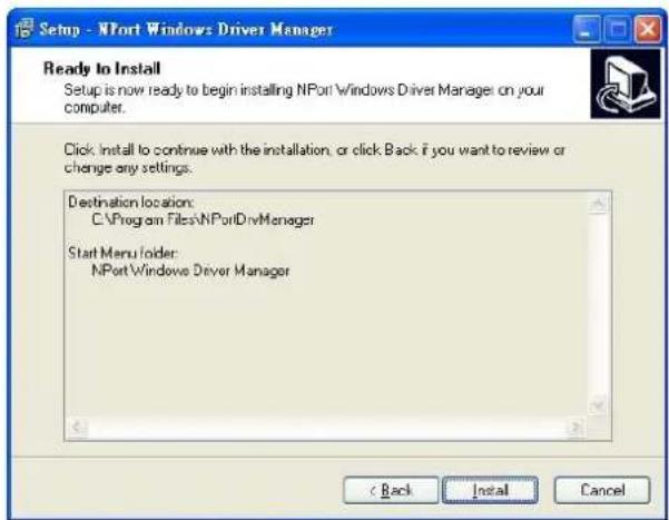
- The installer will display a summary of the installation options. Click Install to begin the installation. The setup window will report the progress of the installation. To change the installation settings, click Back and navigate to the previous screen.
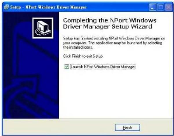
- Click Finish to complete the installation of NPort Windows Driver Manager.
Using NPort Windows Driver Manager
After you install NPort Windows Driver Manager, you can set up the MiiNePort's serial port, which is connected to your device's main board, as remote COM ports for your PC host. Make sure that the serial port on your MiiNePort is already set to Real COM mode when mapping COM ports with the NPort Windows Driver Manager.
NOTE Refer to Chapter 7: Web Console Configuration to learn how to configure your MiiNePort to Real COM mode.
- Go to Start → NPort Windows Driver Manager → NPort Windows Driver Manager to start the COM mapping utility.
- Click the Add icon.

Note: Users running Windows Vista and Windows 7 will see a "User Account Control" popup and should allow the program.
- Click Search to search for the MiiNePort modules. From the list that is generated, select the server to which you will map COM ports, and then click OK.
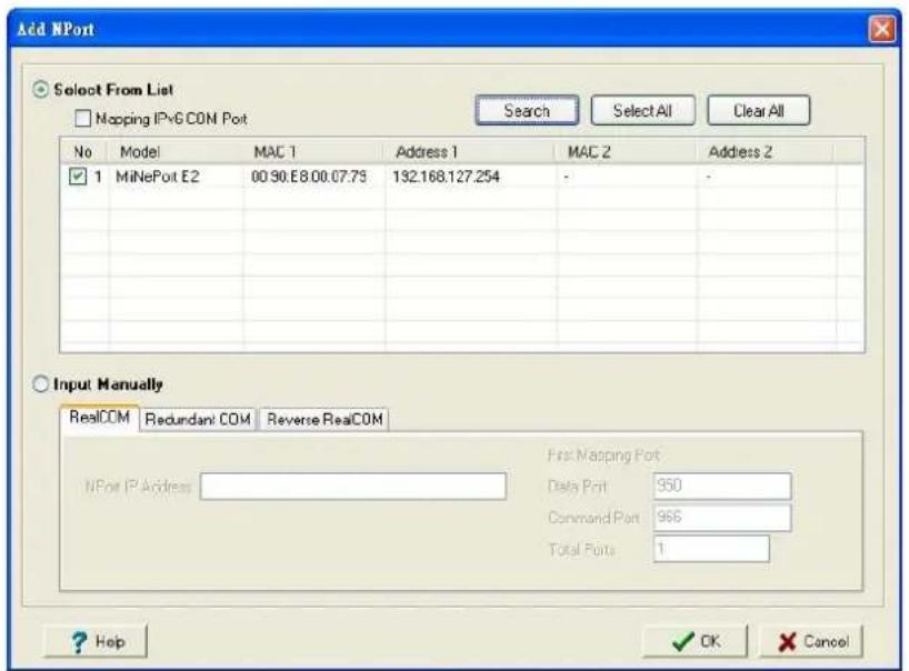
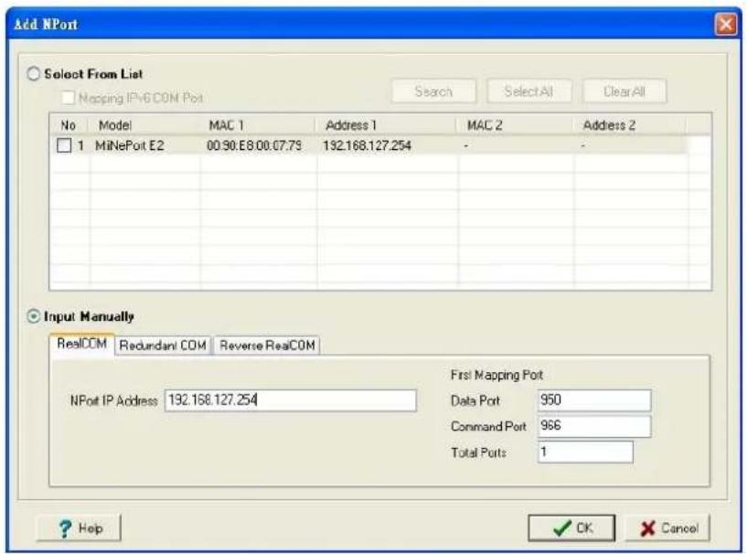
- Alternatively, you can select Input Manually and then manually enter the MiiNePort module's IP Address, 1st Data Port, 1st Command Port, and Total Ports to which COM ports will be mapped. Click OK to proceed to the next step. Note that the Add NPort page supports FQDN (Fully Qualified Domain Name), in which case the IP address will be filled in automatically.
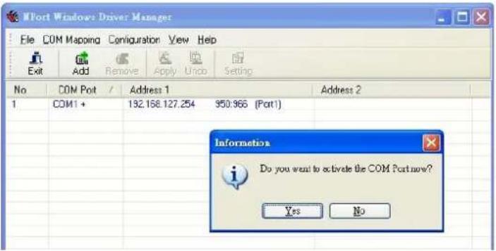
- COM ports and their mappings will appear in blue until they are activated. Activating the COM ports saves the information in the host system registry and makes the COM port available for use. The host computer will not have the ability to use the COM port until the COM ports are activated. Click Yes to activate the COM ports at this time, or click No to activate the COM ports later.
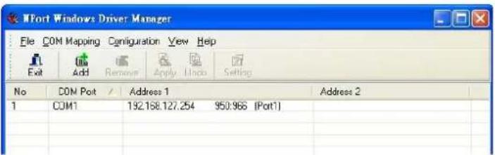
- Ports that have been activated will appear in black.
The Linux Real TTY Driver
- Obtain the driver file from the included CD-ROM or the Moxa website, at http://www.moxa.com.
- Log in to the console as a super user (root).
- Execute cd / to go to the root directory.
- Copy the driver file npreal2xx.tgz to the / directory.
- Execute tar xvfz npreal2xx.tgz to extract all files into the system.
- Execute /tmp/moxa/mxinst.
For RedHat AS/ES/WS and Fedora Core1, append an extra argument as follows:
# /tmp/moxa/mxinst SP1
The shell script will install the driver files automatically.
- After installing the driver, you will be able to see several files in the /usr/lib/npreal2/driver folder:
mxaddsvr (Add Server, mapping tty port)
mxdelsvr (Delete Server, un-mapping tty port)
mxloadsvr (Reload Server)
mxmknod (Create device node/tty port)
mxrmnod (Remove device node/tty port)
mxuninst (Remove tty port and driver files)
At this point, you will be ready to map the MiiNePort serial port to the system tty port.
Mapping TTY Ports
Be sure to set the operation mode of the serial port of the MiiNePort to Real COM mode. After logging in as a super user, enter the directory /usr/lib/npreal2/driver and then execute mxaddsvr to map the target MiiNePort serial port to the host tty ports. The syntax of mxaddsvr is as follows:
mxaddsvr [MiiNePort IP Address] [Total Ports] ([Data port] [Cmd port])
The mxaddsvr command performs the following actions:
-
Modifies npreal2d.cf.
-
Creates tty ports in directory /dev with major and minor number configured in npreal2d.cf.
- Restarts the driver.
Mapping tty ports automatically
To map tty ports automatically, execute mxaddsvr with just the IP address and number of ports, as in the following example:
# cd /usr/lib/npreal2/driver
# ./mxaddsvr 192.168.3.4 16
In this example, 16 tty ports will be added, all with IP 192.168.3.4, with data ports from 950 to 965 and command ports from 966 to 981.
Mapping tty ports manually
To map tty ports manually, execute mxaddsvr and manually specify the data and command ports, as in the following example:
# cd /usr/lib/npreal2/driver
# ./mxaddsvr 192.168.3.4 16 4001 966
In this example, 16 tty ports will be added, all with IP 192.168.3.4, with data ports from 4001 to 4016 and command ports from 966 to 981.
Removing Mapped TTY Ports
After logging in as root, enter the directory /usr/lib/npreal2/driver and then execute mxdelsvr to delete a server. The syntax of mxdelsvr is:
mxdelsvr [IP Address]
Example:
# cd /usr/lib/npreal2/driver
# ./mxdelsvr 192.168.3.4
The following actions are performed when executing mxdelsvr:
- npreal2d.cf is modified.
- Relevant tty ports in directory /dev are removed.
- The driver is restarted.
If the IP address is not provided in the command line, the program will list the installed servers and total ports on the screen. You will need to choose a server for deletion from the list.
Removing Linux Driver Files
A utility is included that will remove all driver files, mapped tty ports, and unload the driver. To do this, you only need to enter the directory /usr/lib/npreal2/driver, and then execute mxuninst to uninstall the driver.
The following actions will be performed:
- The driver is unloaded.
- All files and directories in /usr/lib/npreal2 are deleted.
- The directory /usr/lib/npreal2 is deleted.
- The script file that initializes the system is modified.
The UNIX Fixed TTY Driver
Installing the UNIX Driver
- Log in to UNIX and create a directory for the Moxa TTY. To create a directory named /usr/etc, execute the command:
mkdir -p /usr/etc
- Copy moxattyd.tar to the directory you created. If you created the /usr/etc directory above, you would execute the following commands:
cp moxattyd.tar /usr/etc
cd /usr/etc
- Extract the source files from the tar file by executing the command:
tar xvf moxattyd.tar
The following files will be extracted:
README.TXT
moxattyd.c --- source code
moxattyd.cf --- an empty configuration file
Makefile --- makefile
VERSION.TXT --- fixed tty driver version
FAQ.TXT
- Compile and Link
For SCO UNIX:
# make sco
For UnixWare 7:
# make svr5
For UnixWare 2.1.x, SVR4.2:
# make svr42
Configuring the UNIX Driver
Modify the configuration:
The configuration used by the moxattyd program is defined in the text file moxattyd.cf, which is in the same directory that contains the program moxattyd. You may use vi, or any text editor to modify the file, as follows:
ttyp1 192.168.1.1 950
For more configuration information, view the file moxattyd.cf, which contains detailed descriptions of the various configuration parameters.
NOTE
The "Device Name" depends on the OS. See the Device Naming Rule section in README.TXT for more information.
Start the moxattyd daemon that you configured in moxattyd.cf. If you would like to set the connection timeout, you can add a "-t min" parameter to specify the connection timeout value in minutes. For example:
# /usr/etc/moxattyd/moxattyd -t 1
NOTE You will now be able to use tty, which is configured in moxattyd.cf.
To start the moxattyd daemon after system bootup, add an entry into /etc/inittab, with the tty name you configured in moxattyd.cf, as in the following example:
ts:2:respawn:/usr/etc/moxattyd/moxattyd -t 1
Device naming rule
For UnixWare 7, UnixWare 2.1.x, and SVR4.2, use:
pts/[n]
For all other UNIX operating systems, use:
ttyp[n]
Adding an additional server
- Modify the text file moxattyd.cf to add an additional server. You may use vi or any text editor to modify the file. For more configuration information, look at the file moxattyd.cf, which contains detailed descriptions of the various configuration parameters.
- Find the process ID (PID) of the program moxattyd.
# ps -ef | grep moxattyd
- Update configuration of the moxattyd program.
<h1 id="kill-usr1-pid">kill -USR1 [PID]</h1>
(e.g., if moxattyd PID = 404, kill -USR1 404)
Execute the moxattyd program again to activate the new settings, as follows:
# /usr/etc/moxattyd/moxattyd -t 1
This completes the process of adding an additional server.
The web console is the most user-friendly way to configure your MiiNePort Series module. This chapter introduces the web console function groups and function definitions.
The following topics are covered in this chapter:
□ Opening Your Brower
□ Web Console Fundamentals
□ Basic Settings
Network Settings
What is IPv6?
Serial Port Settings
➢ Operation Modes
□ Advanced Settings
Accessible IP List
SNMP Agent
DIO Settings
Serial Command Mode (SCM)
Miscellaneous
□ Maintenance
Console Settings
➢ Firmware Upgrade
Configuration Tools
Change Password
Opening Your Brower
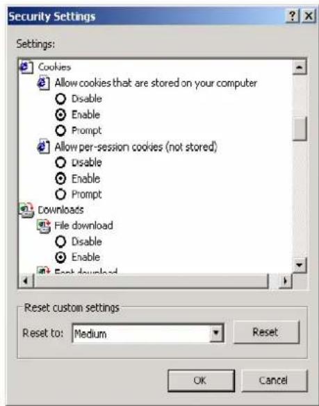
- Open your browser with the cookie function enabled. (To enable your Internet Explorer for cookies, right click on your desktop Internet Explorer icon, select Properties, click on the Security tab, and then select the three Enable options as shown in the figure below.)

- Type 192.168.127.254 in the Address box (use the correct IP address if different from the default), and then press Enter.

ATTENTION
If you use other web browsers, remember to enable the functions to "allow cookies that are stored on your computer" or "allow per-session cookies." MiiNePort modules only use cookies for password transmission.

ATTENTION
Refer to Chapter 5: Initial IP Address Configuration for instructions on IP configuration. The examples in this chapter use the factory default IP address (192.168.127.254).
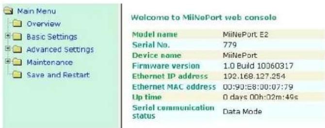
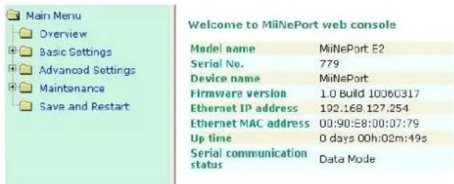
- The web console will open. On this page, you can see a brief description of the web console's function groups in the left part of the page. You can also see a configuration overview of your MiiNePort module.
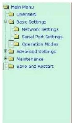
Web Console Fundamentals
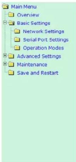
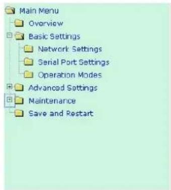
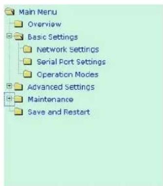
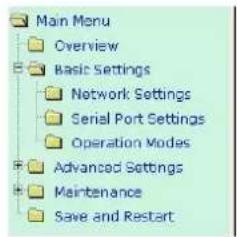
In the web console, the left panel is the navigation panel. It contains an expandable menu tree for navigating among the various settings and categories. When you click on a menu item in the navigation panel, the main window will display the corresponding options for that item.
Configuration changes can then be made in the main window. For example, if you click on Basic Settings → Network Settings in the navigation panel, the main window will show a page of network settings that you can configure.
You must click on the Submit button to keep your configuration changes. The Submit button will be located at the bottom of every page that has configurable settings. If you navigate to another page without clicking the Submit button, your settings will not be retained.
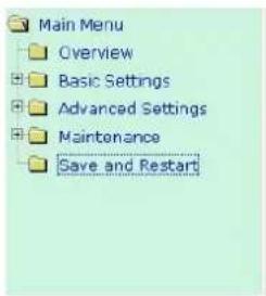
Changes will not take effect until they are saved and the module is restarted! You may complete this in one step by clicking on Save/Restart after you submit a change. If you restart the module without saving your configuration, the module will discard all submitted changes.
Save Configuration OK!
Your configuration has been saved and your settings will take effect when the server is restarted. Click on Restart to reboot the MiNePort E2 server now.

Basic Settings
Network Settings
Network Settings
Device name
IP configuration
IP address
Netmask
Gateway
DNS server 1
DNS server 2
IPv6 Configuration
IPv6 Address
IPv6 Address Prefix
IPv6 Default Gateway
MiiNePort-E1
Static
192.168.127.254
255.255.255.0

Auto

Submit
You must assign a valid IP address to the module before it will work in your network environment. Your network system administrator should provide you with an IP address and related settings for your network. The IP address must be unique within the network; otherwise the module will not have a valid connection to the network. First time users can refer to Chapter 5: Initial IP Address Configuration for more information.
Device name
| Setting | Factory Default | Necessity |
| 1 to 39 characters | [model name]_[Serial No.] | Optional |
This option can be used to specify the location or application of the module, which may be useful when managing more than one module on the network.
IP configuration
| Method | Function Definition |
| Static | User defined IP address, Netmask, Gateway. |
| DHCP | DHCP Server assigned IP address, Netmask, Gateway, DNS |
| DHCP/BOOTP | DHCP Server assigned IP address, Netmask, Gateway, DNS, or BOOTP Server assigned IP address |
| BOOTP | BOOTP Server assigned IP address |
| AUTOIP | AUTOIP protocols automatically negotiate and assign IP in 169.254/16 network |
IP configuration is a required field. The default setting is Static.

ATTENTION
In Dynamic IP environments, the module will attempt to obtain an IP address from the DHCP or BOOTP server 3 times at 30-second intervals. The timeout for the first try will be 1 second, the second try will be 3 seconds, and the last try will be 5 seconds.
If the DHCP/BOOTP Server is unavailable, the module will use the default IP address (192.168.127.254), netmask, and gateway settings.
IP Address
| Setting | Description | Factory Default |
| E.g., 192.168.1.1(IP addresses of the form x.x.x.0 and x.x.x.255 are invalid.) | 192.168.127.254 | Required |
An IP address is a number assigned to a network device, such as a computer, as a permanent address on the network. Computers use the IP address to identify and talk to each other over the network. Choose a proper IP address that is unique and valid in your network environment.
Netmask
| Setting | Factory Default | Necessity |
| E.g., 255.255.255.0 | 255.255.255.0 | Required |
A subnet mask represents all the network hosts at one geographic location, in one building, or on the same local area network. When a packet is sent out over the network, the module will use the subnet mask to check whether the host specified in the packet is on a local network segment. If the address is on the same network segment as the module, a connection is established directly from the module. Otherwise, the connection is established through the default gateway.
Gateway
| Setting | Factory Default | Necessity |
| E.g., 192.168.1.1 | None | Optional |
A gateway acts as an entrance to another network. Usually, the computers that control traffic within the network or at the local Internet service provider are gateway nodes. The module needs to know the IP address of the default gateway computer in order to communicate with the hosts outside the local network environment. For correct gateway IP address information, consult your network administrator.
DNS server 1 / DNS server 2
| Setting | Factory Default | Necessity |
| E.g., 192.168.1.1 (IP addresses of the form x.x.x.0 and x.x.x.255 are invalid) | None | Optional |
The Domain Name System (DNS) is used to identify and translate Internet domain names into IP addresses. A domain name is an alphanumeric name, such as moxa.com, that is usually easier to remember. A DNS server is a host that translates the text-based domain name into the corresponding numeric IP address, which is used to establish a TCP/IP connection. When the user enters a website address, the computer asks a DNS server for the website's IP address to connect to the web server.
When a DNS server is specified, the module acts as a DNS client and will allow domain names instead of IP addresses to be used on the web console. The following web console fields support the use of domain names: TCP Client-Destination IP Address, and IP Address Report Server. Two DNS servers can be specified, DNS server 1 and DNS server 2. DNS server 2 is included for use when DNS sever 1 is unavailable.
What is IPv6?
IPv6 stands for Internet Protocol version 6. It is the second version of the Internet Protocol, introduced after the first version, which is IPv4. The difference between the two versions is the length of the IP address. IPv4 uses 32-bit IP addresses, and IPv6 uses 128-bit IP addresses. IPv4 is still the predominant protocol used over most of the Internet.
IPv6 Configuration (default=Auto): You can choose from three possible IP configuration modes.
| Option | Description |
| Auto | IPv6 router assigned prefixStep 1: The MiiNePort generates the Link local address automaticallyStep 2: The MiiNePort sends the "Router solicitation" to the router to apply for an IP address.2.1 The router assigns an IP address to the MiiNeport → Step 42.2 The router assigns the DHCPv6 Server to offer an IP address → Step 32.3 The router has no response (e.g., the router does not exist) → Step 3Step 3: The MiiNePort applies for an IP address from the DHCPv6 ServerStep 4: Process closed |
| Static | User-defined IP address, Prefix, gateway. |
IPv6 Address: Enter the IPv6 address that will be assigned to your MiiNePort. All ports on the MiiNePort will share this IPv6 address. An IPv6 address is a number assigned to a network device (such as a computer) as a permanent address on the network. Computers use the IPv6 address to identify and talk to each other over the network. Choose a proper IPv6 address that is unique and valid in your network environment.
IPv6 Address Prefix: The prefix is the part of the address that indicates the bits that have fixed values or are the bits of the subnet prefix. Prefixes for IPv6 subnets, routes, and address ranges are expressed in the same way as Classless Inter-Domain Routing (CIDR) notation for IPv4. An IPv6 prefix is written in address/prefix-length notation. For example, 21DA:D3::/48 and 21DA:D3:0:2F3B::/64 are IPv6 address prefixes. Note: IPv4 implementations commonly use a dotted decimal representation of the network prefix known as the subnet mask. A subnet mask is not used for IPv6. Only the prefix length notation is supported.
IPv6 Default Gateway : Enter the IPv6 address of the gateway if applicable. A gateway is a network computer that acts as an entrance to another network. Usually, the computers that control traffic within the network or at the local Internet service provider are gateway nodes. The MiiNePort needs to know the IPv6 address of the default gateway computer in order to communicate with the hosts outside the local network environment. For correct gateway IPv6 address information, consult the network administrator.
Serial Port Settings
![Communication Parameters Port alias Serial Parameters Baud rate [Hint] 115200 Data bits 8 Stop bits 1 Parity None Flow control RTS/CTS FIFO Enable Disable Interface RS-422/RS-485 Submit](/content/2026/05/1143673/images/bb09f7abeb8665014959a8c330dc7ab0ec6f67046022b0b1ab334849bd008fcf.jpg)
Port Alias
| Setting | Factory Default | Necessity |
| 1 to 15 characters (E.g., PLC-No.1) | None | Optional |
This function is designed for future use. You may enter a string to help in the module's serial port from other serial ports.

ATTENTION
Refer to the serial communication parameters in your serial device's user's manual. The module's serial parameters should be the same as the parameters used by your serial device.
Baudrate
| Setting | Factory Default | Necessity |
| 50 bps to 921.6 Kbps (supports non-standard baudrates) | 115.2 Kbps | Required |
![Communication Parameters Port alias Serial Parameters Baud rate [Hint] 115200 Data bits 8 Stop bits 1 Parity None Flow control RTS/CTS FIFO Enable Disable Interface RS-422/RS-485 Submit](/content/2026/05/1143673/images/07e7e397bc2fed66f2a86b4c9663d10fec617060c042c30b8028d9968263e9a7.jpg)
The MiiNePort supports the Any Baudrate (non-standard baudrate) feature. If your baudrate is not listed, select Other from the drop-down list and type the baudrate in the input box. The MiiNePort will use the closest baudrate that is supported.
![Main Menu Overview Basic Settings Network Settings Serial Port Settings Operation Modes Advanced Settings Maintenance Save and Restart Communication Parameters Port alias Serial Parameters Baud rate [Hint] Other Data bits 8 Stop bits 1 Parity None Flow control RTS/CTS FIFO Enable Disable Interface RS-422/RS-435 Submit](/content/2026/05/1143673/images/8ad7ff34eec7cb9e5dbeb65cb83ad6c4f4d606abb6ea296d18059361f49faf90.jpg)
Data Bits
| Setting | Factory Default | Necessity |
| 5, 6, 7, 8 | 8 | Required |
Stop Bits
| Setting | Factory Default | Necessity |
| 1, 1.5, 2 | 1 | Required |
Stop Bits will be set to 1.5 when Data Bits is set to 5 bits.
Parity
| Setting | Factory Default | Necessity |
| None, Even, Odd, Space, Mark | None | Required |
Flow control
| Setting | Factory Default | Necessity |
| None, RTS/CTS,DTR/DSR, XON/XOFF | RTS/CTS | Required |
FIFO
| Setting | Factory Default | Necessity |
| Enable, Disable | Enable | Required |
Each module's serial port provides a 128-byte FIFO both in the Tx and Rx directions. Disable the FIFO setting when your serial device does not have a FIFO to prevent data loss during communication.
Interface
| Setting | Description | Necessity |
| RS-232/422/485 | RS-232,RS-422/485 | Required |
Operation Modes

Operation Modes
Mode
TCP alive check time
Inactivity time
Max connection
Ignore jammed IP
Allow driver control
Local TCP port
Command port
TCP Server
7 (0 - 99 min)
0 (0 - 65535 ms)
1
Enable Disable
Enable Disable
4001
956
Data Packing
Submit
Before reading this section, refer to Chapter 3: Choosing the Proper Operation Mode to select the operation mode that best fits your device application.
Click Operation Modes, located under the Main Menu, to display the operating settings for the MiiNePort's two serial ports.
Disable Mode
Operation Modes
Mode

Submit
When Mode is set to Disable, that particular port will be disabled. Check Apply the above settings to all serial ports to apply this setting to all ports.
Real COM Mode
Operation Modes
Mode
TCP alive check time
Max connection
Ignore jammed IP
Allow driver control
Real COM
7 (0 - 99 min)
1
Enable ☑ Disable
Enable Disable
Data Packing
Packet length
Delin
Delimiter 2
Delimiter process
Force transmit
0 (0 - 1024)
00 (Hex) □ Enable
00 (Hex) Enable
Do nothing
0 (0 - 65535 ms)
Submit

ATTENTION
To use Real COM mode, refer to Chapter 6: Utility Console and Driver Installation for instructions on how to install the Real COM driver on Windows or Linux machines.
TCP alive check time
| Setting | Factory Default | Necessity |
| 0 to 99 min | 7 min | Optional |
0 min: The TCP connection is not closed due to an idle TCP connection.
1 to 99 min: The module automatically closes the TCP connection if there is no TCP activity for the given time. After the connection is closed, the module starts listening for another host's TCP connection.
Max connection
| Setting | Factory Default | Necessity |
| 1, 2, 3, 4 | 1 | Required |
Max connection is used when the device needs to receive data from different hosts simultaneously.
The factory default only allows 1 connection at a time. When Max Connection is set to 1, the Real COM driver on the specific host has full control.
Max connection 1: The module will only allow 1 host's Real COM driver to open a connection to the module's serial port.
Max connections 2 to 4: When set to 2 or higher, Real COM drivers for up to the specified number of hosts may open this port at the same time. When Real COM drivers for multiple hosts open the port at the same time, the COM driver only provides a pure data tunnel with no control ability. The serial port parameters will use firmware settings instead of your application program (AP) settings.
Application software that is based on the COM driver will receive a driver response of "success" when the software uses any of the Win32 API functions. The firmware will only send data back to the driver on the host. Data will be sent first-in-first-out when data is received by the MiiNePort from the Ethernet interface.

ATTENTION
When Max connection is greater than 1, the MiiNePort module will use a multiple connection application (i.e., 2 to 4 hosts are allowed access to the port at the same time). When using a multi connection application, the module will use the serial communication parameters as defined here in the web console, and all hosts connected to the port must use identical serial settings. If one of the hosts opens the COM port with different serial settings, data will not be transmitted properly.
Ignore jammed IP
| Setting | Factory Default | Necessity |
| Enable, Disable | Disable | Required when Max connection is greater than 1 |
This option determines how the port will proceed if multiple hosts are connected and one or more of the hosts stops responding as the port is transmitting data. If you select Disable, the port will wait until the data has been transmitted successfully to all hosts before transmitting the next group of data. If you select Enable, the port will ignore the host that stopped responding and continue data transmission to the other hosts.
NOTE Ignore Jammed IP is only active when Max connection is greater than 1.
Allow driver control
| Setting | Factory Default | Necessity |
| Enable, Disable | Enable | Required when Max connection is greater than 1 |
This option determines how the port will proceed if driver control commands are received from multiple hosts that are connected to the port. If Disable is selected, driver control commands will be ignored. If Enable is selected, control commands will be accepted, with the most recent command received taking precedence.
NOTE Allow driver control is only active when Max connection is greater than 1.
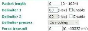
Packet length
| Setting | Factory Default | Necessity |
| 0 to 1024 bytes | 0 byte | Required |
The Packet length setting refers to the maximum amount of data that is allowed to accumulate in the serial port buffer before sending. When packet length is set to 0 (the default), a maximum amount is not specified and data in the buffer will be sent as specified by the delimiter settings or when the buffer is full. When a packet length between 1 and 1024 bytes is specified, data in the buffer will be sent as soon as it reaches the specified length.
Delimiter 1
| Setting | Factory Default | Necessity |
| 00 to FF | "0" for None | Optional |
Delimiter 2
| Setting | Factory Default | Necessity |
| 00 to FF | "0" for None | Optional |
The Delimiter fields are used to specify a 1-character or 2-character sequence that acts as a marker to control packing of serial data. By default, delimiter characters are not defined, so the module transmits data as soon as it is received. When a delimiter character or characters are defined, the module will hold data in its buffer until it receives the delimiter character or 2-character sequence. When the delimiter is received, the module will pack the data into its buffer and send it out through the Ethernet port.
Use Delimiter 1 to define the first delimiter character in hex. If only one delimiter character is used, Delimiter 2 should be set to "0". If the delimiter is a two-character sequence, use Delimiter 2 to define the second character. To disable the use of delimiters, set both Delimiter 1 and Delimiter 2 to "0".
Note that data packing is controlled not only by the delimiter but is also influenced by the module's buffer size and the Force transmit field. If the delimiter has not been received by the time the 1K buffer is full, the module will pack the data for network transmission and clear the buffer. In addition, the module will also pack data for network transmission if the next byte of data is not received within the Force transmit time.

ATTENTION
Delimiter 2 is optional. If left blank, then Delimiter 1 alone trips clearing of the buffer. If the size of the serial data received is greater than 1 KB, the MiiNePort will automatically pack the data and send it to the Ethernet. However, to use the delimiter function, you must at least enable Delimiter 1. If Delimiter 1 is left blank and Delimiter 2 is enabled, the delimiter function will not work properly.
Delimiter process
| Setting | Factory Default | Necessity |
| Do Nothing, Delimiter+1, Delimiter+2, Strip Delimiter | Do Nothing (only effective when Delimiter is enabled) | Optional |
The Delimiter process field determines how the data is handled when a delimiter is received. Delimiter 1 must be enabled for this field to have effect. If Delimiters 1 and 2 are both enabled, both characters must be received for the delimiter process to take place.
[Do Nothing]: Data in the buffer will be transmitted when the delimiter is received.
[Delimiter + 1] or [Delimiter + 2]: The data will be transmitted when an additional byte (for Delimiter + 1), or an additional 2 bytes (for Delimiter + 2) of data is received after receiving the Delimiter.
[Strip Delimiter]: When the Delimiter is received, the Delimiter is deleted (i.e., stripped), and the remaining data is transmitted.
Force transmit
| Setting | Factory Default | Necessity |
| 0 to 65535 ms | 0 ms | Optional |
0: The force transmit timeout is disabled.
1 to 65535: If the module does not receive the next byte of data within the time specified, it will pack the data in its buffer into the same data frame for network transmission.
The Force transmit field is typically used in conjunction with the Delimiter fields to specify how data in the module's buffer is packed for network transmission. When delimiters are used, the module accumulates data in its buffer as it waits to receive a delimiter. If there is a break in communication, data will be held in the buffer as the module continues to wait for a delimiter. The Force transmit field allows you to specify the maximum amount of time that the module will wait for data. With Force transmit enabled, the module will automatically pack the data in the buffer for network transmission if no data is received for the specified time.
When set to 0, Force transmit is disabled, which means there is no time limit for how long the module will wait to receive data. When set between 1 and 65535, the module will pack data if serial data is not received in the specified time.
The optimal force transmit time depends on your application, but it should be larger than one character interval within the specified baudrate to have any effect. For example, assume that the serial port is set to 1200 bps, 8 data bits, 1 stop bit, and no parity. In this case, the total number of bits needed to send one character is 10 bits, and the time required to transfer one character is
(10 bits / 1200 bits/s) × 1000 ms/s = 8.3 ms.
Since it requires about 9 ms to send one character, the Force transmit should be 10 ms or more to have any effect. At 9 ms or less, the module will simply pack every character as it is received, which would be the same as if delimiter characters or a Force transmit time were not specified.
RFC 2217 Mode
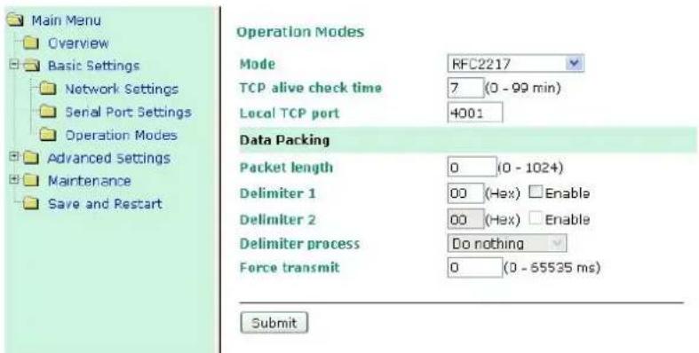
TCP alive check time
| Setting | Factory Default | Necessity |
| 0 to 99 min | 7 min | Optional |
0 min: TCP connection is not closed due to an idle TCP connection.
1 to 99 min: The MiiNePort automatically closes the TCP connection if there is no TCP activity for the given time. After the connection is closed, the MiiNePort starts listening for another host's TCP connection.
Local TCP port
| Setting | Factory Default | Necessity |
| 1 to 65535 | 4001 | Required |
The Local TCP port is the TCP port that the MiiNePort uses to listen to connections, and that other devices must use to contact the MiiNePort. To avoid conflicts with well known TCP ports, the default is set to 4001.
Packet length
| Setting | Factory Default | Necessity |
| 0 to 1024 | 0 | Optional |
The Packet length setting refers to the maximum amount of data that is allowed to accumulate in the serial port buffer before sending. When packet length is set to 0 (the default), a maximum amount is not specified and data in the buffer will be sent as specified by the delimiter settings or when the buffer is full. When a packet length between 1 and 1024 bytes is specified, data in the buffer will be sent as soon as it reaches the specified length.
Delimiter 1
| Setting | Factory Default | Necessity |
| 00 to FF | None | Optional |
Delimiter 2
| Setting | Factory Default | Necessity |
| 00 to FF | None | Optional |
The Delimiter fields are used to specify a 1-character or 2-character sequence that acts as a marker to control packing of serial data. By default, delimiter characters are not defined, so the module transmits data as soon as it is received. When a delimiter character or characters are defined, the module will hold data in its buffer until it receives the delimiter character or 2-character sequence. When the delimiter is received, the module will pack the data into its buffer and send it out through the Ethernet port.
Use Delimiter 1 to define the first delimiter character in hex. If only one delimiter character is used, Delimiter 2 should be set to "0". If the delimiter is a two-character sequence, use Delimiter 2 to define the second character. To disable the use of delimiters, set both Delimiter 1 and Delimiter 2 to "0".
Note that data packing is controlled not only by the delimiter but is also influenced by the module's buffer size and the Force transmit field. If the delimiter has not been received by the time the 1K buffer is full, the module will pack the data for network transmission and clear the buffer. In addition, the module will also pack data for network transmission if the next byte of data is not received within the Force transmit time.
Delimiter process
| Setting | Factory Default | Necessity |
| Do Nothing, Delimiter +1, Delimiter +2, Strip Delimiter | Do Nothing | Optional |
The Delimiter process field determines how the data is handled when a delimiter is received. Delimiter 1 must be enabled for this field to have effect. If Delimiters 1 and 2 are both enabled, both characters must be received for the delimiter process to take place.
[Do Nothing]: Data in the buffer will be transmitted when the delimiter is received.
[Delimiter + 1] or [Delimiter + 2]: The data will be transmitted when an additional byte (for Delimiter + 1), or an additional 2 bytes (for Delimiter + 2) of data is received after receiving the Delimiter.
[Strip Delimiter]: When the Delimiter is received, the Delimiter is deleted (i.e., stripped), and the remaining data is transmitted.
Force transmit
| Setting | Factory Default | Necessity |
| 0 to 65535 ms | 0 ms | Optional |
0: The force transmit timeout is disabled.
1 to 65535: If the module does not receive the next byte of data within the time specified, it will pack the data in its buffer into the same data frame for network transmission.
The Force transmit field is typically used in conjunction with the Delimiter fields to specify how data in the module's buffer is packed for network transmission. When delimiters are used, the module accumulates data in its buffer as it waits to receive a delimiter. If there is a break in communication, data will be held in the buffer as the module continues to wait for a delimiter. The Force transmit field allows you to specify the maximum amount of time that the module will wait for data. With Force transmit enabled, the module will automatically pack the data in the buffer for network transmission if no data is received for the specified time.
When set to 0, Force transmit is disabled, which means there is no time limit for how long the module will wait to receive data. When set between 1 and 65535, the module will pack data if serial data is not received in the specified time.
The optimal force transmit time depends on your application, but it should be larger than one character interval within the specified baudrate to have any effect. For example, assume that the serial port is set to 1200 bps, 8 data bits, 1 stop bit, and no parity. In this case, the total number of bits needed to send one character is 10 bits, and the time required to transfer one character is
(10 bits / 1200 bits/s) × 1000 ms/s = 8.3 ms.
Since it requires about 9 ms to send one character, the Force transmit should be 10 ms or more to have any effect. At 9 ms or less, the module will simply pack every character as it is received, which would be the same as ifa delimiter characters or Force transmit time were not specified.

ATTENTION
If you want to send a series of characters in the same packet, the serial device attached to the MiiNePort should send that series of characters during a time interval less than the Force transmit timeout for the MiiNePort, and the total length of data must be less than or equal to the MiiNePort's internal buffer size. The serial communication buffer size for the MiiNePort is 1 KB per port.
TCP Server Mode
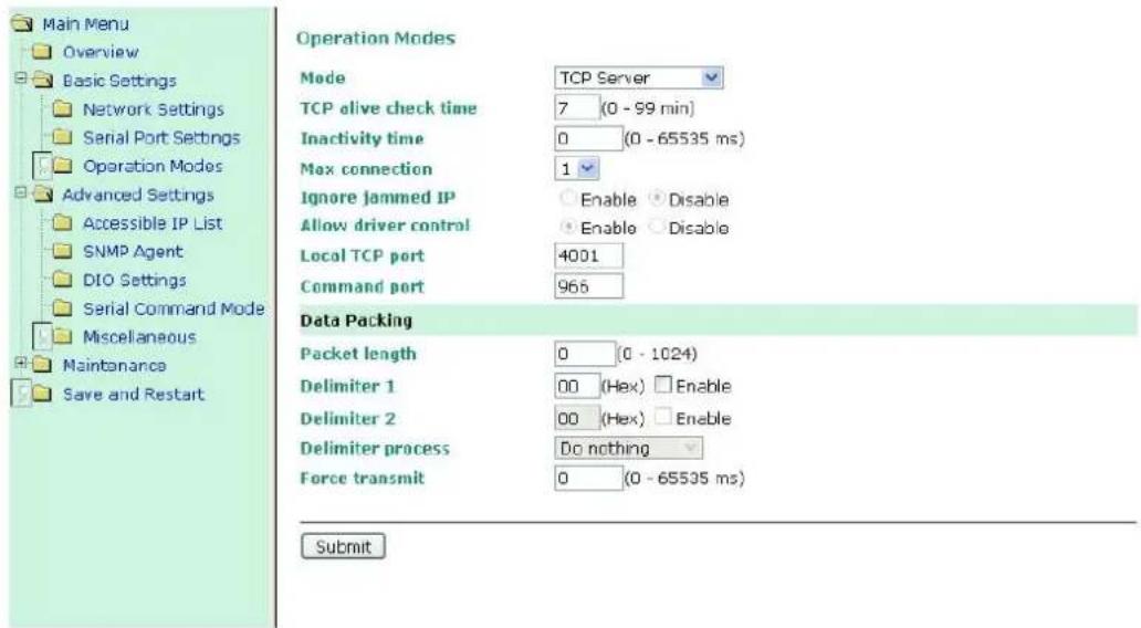
TCP alive check time
| Setting | Factory Default | Necessity |
| 0 to 99 min | 7 min | Optional |
0 min: TCP connection is not closed due to an idle TCP connection.
1 to 99 min: The MiiNePort automatically closes the TCP connection if there is no TCP activity for the given time. After the connection is closed, the MiiNePort starts listening for another host's TCP connection.
Inactivity time
| Setting | Factory Default | Necessity |
| 0 to 65535 ms | 0 ms | Optional |
0 ms: TCP connection is not closed due to an idle serial line.
0-65535 ms: The MiiNePort automatically closes the TCP connection if there is no serial data activity for the given time. After the connection is closed, the MiiNePort starts listening for another host's TCP connection.
This parameter defines the maintenance status as Closed or Listen for the TCP connection. The connection is closed if there is no incoming or outgoing data through the serial port during the specific Inactivity time.
If the Inactivity time is set to 0, the current TCP connection is kept active until a connection close request is received. Although Inactivity time is disabled, the MiiNePort will check the connection status between the MiiNePort and the remote host by sending "keep alive" packets periodically. If the remote host does not respond to the packet, the MiiNePort assumes that the connection was closed unintentionally. The MiiNePort will then force the existing TCP connection to close.

ATTENTION
The Inactivity time should be greater than the Force transmit timeout. To prevent the unintended loss of data due to the session being disconnected, it is highly recommended that this value is set large enough so that the intended data transfer is completed.

ATTENTION
Inactivity time is ONLY active when "TCP connect on" is set to "Any character."
Max connection
| Setting | Factory Default | Necessity |
| 1, 2, 3, 4 | 1 | Required |
Max connection is used when the device needs to receive data from different hosts simultaneously.
The factory default only allows 1 connection at a time. When Max Connection is set to 1, the Real COM driver on the specific host has full control.
Max connection 1: The module will only allow 1 host's Real COM driver to open a connection to the module's serial port.
Max connections 2 to 4: When set to 2 or higher, Real COM drivers for up to the specified number of hosts may open this port at the same time. When Real COM drivers for multiple hosts open the port at the same time, the COM driver only provides a pure data tunnel with no control ability. The serial port parameters will use firmware settings instead of your application program (AP) settings.
Application software that is based on the COM driver will receive a driver response of "success" when the software uses any of the Win32 API functions. The firmware will only send data back to the driver on the host. Data will be sent first-in-first-out when data is received by the MiiNePort from the Ethernet interface.
Ignore jammed IP
| Setting | Factory Default | Necessity |
| Enable, Disable | Disable | Optional |
This option determines how the port will proceed if multiple hosts are connected and one or more of the hosts stops responding as the port is transmitting data. If you select Disable, the port will wait until the data has been
transmitted successfully to all hosts before transmitting the next group of data. If you select Enable, the port will ignore the host that stopped responding and continue data transmission to the other hosts.
NOTE Ignore Jammed IP is only active when Max connection is greater than 1.
Allow driver control
| Setting | Factory Default | Necessity |
| Enable, Disable | Disable | Optional |
This option determines how the port will proceed if driver control commands are received from multiple hosts that are connected to the port. If Disable is selected, driver control commands will be ignored. If Enable is selected, control commands will be accepted, with the most recent command received taking precedence.
NOTE Allow driver control is only active when Max connection is greater than 1.
Local TCP port
| Setting | Factory Default | Necessity |
| 1 to 65535 | 4001 | Required |
The Local TCP port is the TCP port that the MiiNePort uses to listen to connections, and that other devices must use to contact the MiiNePort. To avoid conflicts with well known TCP ports, the default is set to 4001.
Command port
| Setting | Factory Default | Necessity |
| 1 to 65535 | 966 | Optional |
The Command port is a "listen TCP port" for IP-Serial Lib commands from the host. In order to prevent a TCP port conflict with other applications, the user can set the Command port to another port if needed. IP-Serial Lib will automatically check the Command Port on the MiiNePort so that the user does not need to configure the program.
Packet length
| Setting | Factory Default | Necessity |
| 0 to 1024 | 0 | Optional |
The Packet length setting refers to the maximum amount of data that is allowed to accumulate in the serial port buffer before sending. When packet length is set to 0 (the default), a maximum amount is not specified and data in the buffer will be sent as specified by the delimiter settings or when the buffer is full. When a packet length between 1 and 1024 bytes is specified, data in the buffer will be sent as soon as it reaches the specified length.
Delimiter 1
| Setting | Factory Default | Necessity |
| 00 to FF | None | Optional |
Delimiter 2
| Setting | Factory Default | Necessity |
| 00 to FF | None | Optional |
The Delimiter fields are used to specify a 1-character or 2-character sequence that acts as a marker to control packing of serial data. By default, delimiter characters are not defined, so the module transmits data as soon as it is received. When a delimiter character or characters are defined, the module will hold data in its buffer until it receives the delimiter character or 2-character sequence. When the delimiter is received, the module will pack the data into its buffer and send it out through the Ethernet port.
Use Delimiter 1 to define the first delimiter character in hex. If only one delimiter character is used, Delimiter 2 should be set to "0". If the delimiter is a two-character sequence, use Delimiter 2 to define the second character. To disable the use of delimiters, set both Delimiter 1 and Delimiter 2 to "0".
Note that data packing is controlled not only by the delimiter but is also influenced by the module's buffer size and the Force transmit field. If the delimiter has not been received by the time the 1K buffer is full, the module will pack the data for network transmission and clear the buffer. In addition, the module will also pack data for network transmission if the next byte of data is not received within the Force transmit time.

ATTENTION
Delimiter 2 is optional. If left blank, then Delimiter 1 alone trips clearing of the buffer. If the size of the serial data received is greater than 1 KB, the MiiNePort will automatically pack the data and send it to the Ethernet. However, to use the delimiter function, you must at least enable Delimiter 1. If Delimiter 1 is left blank and Delimiter 2 is enabled, the delimiter function will not work properly.
Delimiter process
| Setting | Factory Default | Necessity |
| Do Nothing,Delimiter + 1,Delimiter + 2,Strip Delimiter | Do Nothing | Optional |
The Delimiter process field determines how the data is handled when a delimiter is received. Delimiter 1 must be enabled for this field to have effect. If Delimiters 1 and 2 are both enabled, both characters must be received for the delimiter process to take place.
[Do Nothing]: Data in the buffer will be transmitted when the delimiter is received.
[Delimiter + 1] or [Delimiter + 2]: The data will be transmitted when an additional byte (for Delimiter +1), or an additional 2 bytes (for Delimiter +2) of data is received after receiving the Delimiter.
[Strip Delimiter]: When the Delimiter is received, the Delimiter is deleted (i.e., stripped), and the remaining data is transmitted.
Force transmit
| Setting | Factory Default | Necessity |
| 0 to 65535 ms | 0 ms | Optional |
0: The force transmit timeout is disabled.
1 to 65535: If the module does not receive the next byte of data within the time specified, it will pack the data in its buffer into the same data frame for network transmission.
The Force transmit field is typically used in conjunction with the Delimiter fields to specify how data in the module's buffer is packed for network transmission. When delimiters are used, the module accumulates data in its buffer as it waits to receive a delimiter. If there is a break in communication, data will be held in the buffer as the module continues to wait for a delimiter. The Force transmit field allows you to specify the maximum amount of time that the module will wait for data. With Force transmit enabled, the module will automatically pack the data in the buffer for network transmission if no data is received for the specified time.
When set to 0, Force transmit is disabled, which means there is no time limit for how long the module will wait to receive data. When set between 1 and 65535, the module will pack data if serial data is not received in the specified time.
The optimal force transmit time depends on your application, but it should be larger than one character interval within the specified baudrate to have any effect. For example, assume that the serial port is set to 1200 bps, 8 data bits, 1 stop bit, and no parity. In this case, the total number of bits needed to send one character is 10 bits, and the time required to transfer one character is
(10 bits / 1200 bits/s) × 1000 ms/s = 8.3 ms.
Since it requires about 9 ms to send one character, the Force transmit should be 10 ms or more to have any effect. At 9 ms or less, the module will simply pack every character as it is received, which would be the same as if delimiter characters or a Force transmit time were not specified.

ATTENTION
If you want to send a series of characters in the same packet, the serial device attached to the MiiNePort should send that series of characters during a time interval less than the Force transmit timeout for the MiiNePort, and the total length of data must be less than or equal to the MiiNePort's internal buffer size. The serial communication buffer size for the MiiNePort is 1 KB per port.
TCP Client Mode
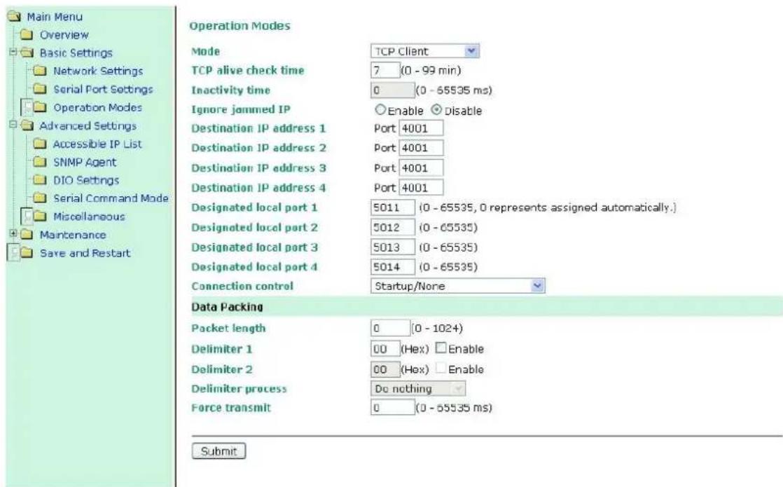
TCP alive check time
| Setting | Factory Default | Necessity |
| 0 to 99 min | 7 min | Optional |
0 min: The TCP connection is not closed due to an idle TCP connection.
1 to 99 min: The module automatically closes the TCP connection if there is no TCP activity for the given time. After the connection is closed, the module starts listening for another host's TCP connection.
Inactivity time
| Setting | Factory Default | Necessity |
| 0 to 65535 ms | 0 ms | Optional |
0 ms: TCP connection is not closed due to an idle serial line.
0-65535 ms: The MiiNePort automatically closes the TCP connection if there is no serial data activity for the given time. After the connection is closed, the MiiNePort starts listening for another host's TCP connection.
This parameter defines the maintenance status as Closed or Listen for the TCP connection. The connection is closed if there is no incoming or outgoing data through the serial port during the specific Inactivity time.
If the Inactivity time is set to 0, the current TCP connection is kept active until a connection close request is received. Although Inactivity time is disabled, the MiiNePort will check the connection status between the MiiNePort and the remote host by sending "keep alive" packets periodically. If the remote host does not respond to the packet, the MiiNePort assumes that the connection was closed unintentionally. The MiiNePort will then force the existing TCP connection to close.

ATTENTION
The Inactivity time should be greater than the Force transmit timeout. To prevent the unintended loss of data due to the session being disconnected, it is highly recommended that this value is set large enough so that the intended data transfer is completed.

ATTENTION
Inactivity time is ONLY active when "TCP connect on" is set to "Any character."
Ignore jammed IP
| Setting | Factory Default | Necessity |
| Enable, Disable | Disable | Optional |
This option determines how the port will proceed if multiple hosts are connected and one or more of the hosts stops responding as the port is transmitting data. If you select Disable, the port will wait until the data has been transmitted successfully to all hosts before transmitting the next group of data. If you select Enable, the port will ignore the host that stopped responding and continue data transmission to the other hosts.
NOTE Ignore Jammed IP is only active when Max connection is greater than 1.
Packet length
| Setting | Factory Default | Necessity |
| 0 to 1024 | 0 | Optional |
The Packet length setting refers to the maximum amount of data that is allowed to accumulate in the serial port buffer before sending. When packet length is set to 0 (the default), a maximum amount is not specified and data in the buffer will be sent as specified by the delimiter settings or when the buffer is full. When a packet length between 1 and 1024 bytes is specified, data in the buffer will be sent as soon as it reaches the specified length.
Delimiter 1
| Setting | Factory Default | Necessity |
| 00 to FF | "00" for None | Optional |
Delimiter 2
| Setting | Factory Default | Necessity |
| 00 to FF | "00" for None | Optional |
The Delimiter fields are used to specify a 1-character or 2-character sequence that acts as a marker to control packing of serial data. By default, delimiter characters are not defined, so the module transmits data as soon as it is received. When a delimiter character or characters are defined, the module will hold data in its buffer until it receives the delimiter character or 2-character sequence. When the delimiter is received, the module will pack the data into its buffer and send it out through the Ethernet port.
Use Delimiter 1 to define the first delimiter character in hex. If only one delimiter character is used, Delimiter 2 should be set to "0". If the delimiter is a two-character sequence, use Delimiter 2 to define the second character. To disable the use of delimiters, set both Delimiter 1 and Delimiter 2 to "0".
Note that data packing is controlled not only by the delimiter but is also influenced by the module's buffer size and the Force transmit field. If the delimiter has not been received by the time the 1K buffer is full, the module will pack the data for network transmission and clear the buffer. In addition, the module will also pack data for network transmission if the next byte of data is not received within the Force transmit time.

ATTENTION
Delimiter 2 is optional. If left blank, then Delimiter 1 alone trips clearing of the buffer. If the size of the serial data received is greater than 1 KB, the MiiNePort will automatically pack the data and send it to the Ethernet. However, to use the delimiter function, you must at least enable Delimiter 1. If Delimiter 1 is left blank and Delimiter 2 is enabled, the delimiter function will not work properly.
Delimiter process
| Setting | Factory Default | Necessity |
| Do Nothing,Delimiter + 1,Delimiter + 2,Strip Delimiter | Do Nothing | Optional |
The Delimiter process field determines how the data is handled when a delimiter is received. Delimiter 1 must be enabled for this field to have effect. If Delimiters 1 and 2 are both enabled, both characters must be received for the delimiter process to take place.
[Do Nothing]: Data in the buffer will be transmitted when the delimiter is received.
[Delimiter + 1] or [Delimiter + 2]: The data will be transmitted when an additional byte (for Delimiter + 1), or an additional 2 bytes (for Delimiter + 2) of data is received after receiving the Delimiter.
[Strip Delimiter]: When the Delimiter is received, the Delimiter is deleted (i.e., stripped), and the remaining data is transmitted.
Force transmit
| Setting | Factory Default | Necessity |
| 0 to 65535 ms | 0 ms | Optional |
0: The force transmit timeout is disabled.
1 to 65535: If the module does not receive the next byte of data within the time specified, it will pack the data in its buffer into the same data frame for network transmission.
The Force transmit field is typically used in conjunction with the Delimiter fields to specify how data in the module's buffer is packed for network transmission. When delimiters are used, the module accumulates data in its buffer as it waits to receive a delimiter. If there is a break in communication, data will be held in the buffer as the module continues to wait for a delimiter. The Force transmit field allows you to specify the maximum amount of time that the module will wait for data. With Force transmit enabled, the module will automatically pack the data in the buffer for network transmission if no data is received for the specified time.
When set to 0, Force transmit is disabled, which means there is no time limit for how long the module will wait to receive data. When set between 1 and 65535, the module will pack data if serial data is not received in the specified time.
The optimal force transmit time depends on your application, but it should be larger than one character interval within the specified baudrate to have any effect. For example, assume that the serial port is set to 1200 bps, 8 data bits, 1 stop bit, and no parity. In this case, the total number of bits needed to send one character is 10 bits, and the time required to transfer one character is
(10 bits / 1200 bits/s) × 1000 ms/s = 8.3 ms.
Since it requires about 9 ms to send one character, the Force transmit should be 10 ms or more to have any effect. At 9 ms or less, the module will simply pack every character as it is received, which would be the same as if delimiter characters or a Force transmit time were not specified.
Destination IP address 1/2/3/4
| Setting | Factory Default | Necessity |
| IP address or Domain Name(E.g., 192.168.1.1) | None | Required |
Up to 4 Destination IP addresses (or domain names) can be specified. The MiiNePort will be able to actively connect to each of these remote addresses.

ATTENTION
The connection speed or throughput may be slow if one of the four connections is slow, since the 1 slow connection will slow down the other 3 connections.

ATTENTION
Both IP address and Domain Name can be used in the "Destination IP address" field.
Designated Local Port 1/2/3/4
| Setting | Factory Default | Necessity |
| TCP Port No. | 5011 (Port 1)5012 (Port 2)5013 (Port 3)5014 (Port 4) | Required |
Connection control
| Setting | Factory Default | Necessity |
| Startup/None, Any Character/None, Any Character/Inactivity Time, DSR ON/DSR OFF, DSR ON/None, DCD ON/DCD OFF, DCD ON/None | Startup/None | Required |
The meaning of each of the above settings is given in the following table. In general, both the Connect condition and Disconnect condition are given.
| Connect/Disconnect | Description |
| Startup / None (default) | A TCP connection will be established on startup, and will remain active indefinite. |
| Any Character / None | A TCP connection will be established when any character is received from the ser interface, and will remain active indefinitely. |
| Any Character / Inactivity Time | A TCP connection will be established when any character is received from the ser interface, and will be disconnected when the Inactivity time out is reached. |
| DSR On / DSR Off | A TCP connection will be established when a DSR “On” signal is received, and will be disconnected when a DSR “Off” signal is received. |
| DSR On / None | A TCP connection will be established when a DSR “On” signal is received, and will remain active indefinitely. |
| DCD On / DCD Off | A TCP connection will be established when a DCD “On” signal is received, and will be disconnected when a DCD “Off” signal is received. |
| DCD On / None | A TCP connection will be established when a DCD “On” signal is received, and will remain active indefinitely. |
UDP Mode
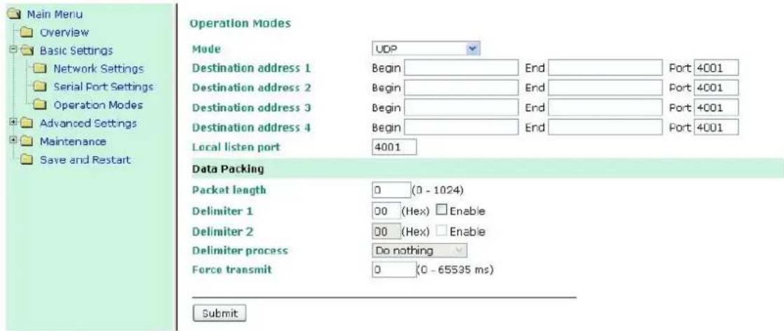
Destination IP address 1
| Setting | Factory Default | Necessity |
| IP address rangeE.g., Begin: 192.168.1.1End: 192.168.1.10 | Begin: Empty | Required |
| End: Empty | ||
| Port: 4001 |
Destination IP address 2/3/4
| Setting | Factory Default | Necessity |
| IP address rangeE.g., Begin: 192.168.1.11End: 192.168.1.20 | Begin: Empty | Optional |
| End: Empty | ||
| Port: 4001 |
Local listen port
| Setting | Factory Default | Necessity |
| 1 to 65535 | 4001 | Required |
The Local listen port is the UDP port that the MiiNePort listens to, and that other devices must use to contact the MiiNePort. To avoid conflicts with well known UDP ports, the default is set to 4001.
Packet length
| Setting | Factory Default | Necessity |
| 0 to 1024 | 0 | Optional |
The Packet length setting refers to the maximum amount of data that is allowed to accumulate in the serial port buffer before sending. When packet length is set to 0 (the default), a maximum amount is not specified and data in the buffer will be sent as specified by the delimiter settings or when the buffer is full. When a packet length between 1 and 1024 bytes is specified, data in the buffer will be sent as soon as it reaches the specified length.
Delimiter 1
| Setting | Factory Default | Necessity |
| 00 to FF | "00" for None | Optional |
Delimiter 2
| Setting | Factory Default | Necessity |
| 00 to FF | "00" for None | Optional |
The Delimiter fields are used to specify a 1-character or 2-character sequence that acts as a marker to control packing of serial data. By default, delimiter characters are not defined, so the module transmits data as soon as it is received. When a delimiter character or characters are defined, the module will hold data in its buffer
until it receives the delimiter character or 2-character sequence. When the delimiter is received, the module will pack the data into its buffer and send it out through the Ethernet port.
Use Delimiter 1 to define the first delimiter character in hex. If only one delimiter character is used, Delimiter 2 should be set to "0". If the delimiter is a two-character sequence, use Delimiter 2 to define the second character. To disable the use of delimiters, set both Delimiter 1 and Delimiter 2 to "0".
Note that data packing is controlled not only by the delimiter but is also influenced by the module's buffer size and the Force transmit field. If the delimiter has not been received by the time the 1K buffer is full, the module will pack the data for network transmission and clear the buffer. In addition, the module will also pack data for network transmission if the next byte of data is not received within the Force transmit time.

ATTENTION
Delimiter 2 is optional. If left blank, then Delimiter 1 alone trips clearing of the buffer. If the size of the serial data received is greater than 1 KB, the MiiNePort will automatically pack the data and send it to the Ethernet. However, to use the delimiter function, you must at least enable Delimiter 1. If Delimiter 1 is left blank and Delimiter 2 is enabled, the delimiter function will not work properly.
Delimiter process
| Setting | Factory Default | Necessity |
| Do Nothing, Delimiter + 1, Delimiter + 2, Strip Delimiter | Do Nothing | Optional |
The Delimiter process field determines how the data is handled when a delimiter is received. Delimiter 1 must be enabled for this field to have effect. If Delimiters 1 and 2 are both enabled, both characters must be received for the delimiter process to take place.
[Do Nothing]: Data in the buffer will be transmitted when the delimiter is received.
[Delimiter + 1] or [Delimiter + 2]: The data will be transmitted when an additional byte (for Delimiter +1), or an additional 2 bytes (for Delimiter +2) of data is received after receiving the Delimiter.
[Strip Delimiter]: When the Delimiter is received, the Delimiter is deleted (i.e., stripped), and the remaining data is transmitted.
Force transmit
| Setting | Factory Default | Necessity |
| 0 to 65535 ms | 0 ms | Optional |
0: The force transmit timeout is disabled.
1 to 65535: If the module does not receive the next byte of data within the time specified, it will pack the data in its buffer into the same data frame for network transmission.
The Force transmit field is typically used in conjunction with the Delimiter fields to specify how data in the module's buffer is packed for network transmission. When delimiters are used, the module accumulates data in its buffer as it waits to receive a delimiter. If there is a break in communication, data will be held in the buffer as the module continues to wait for a delimiter. The Force transmit field allows you to specify the maximum amount of time that the module will wait for data. With Force transmit enabled, the module will automatically pack the data in the buffer for network transmission if no data is received for the specified time.
When set to 0, Force transmit is disabled, which means there is no time limit for how long the module will wait to receive data. When set between 1 and 65535, the module will pack data if serial data is not received in the specified time.
The optimal force transmit time depends on your application, but it should be larger than one character interval within the specified baudrate to have any effect. For example, assume that the serial port is set to 1200 bps,
8 data bits, 1 stop bit, and no parity. In this case, the total number of bits needed to send one character is 10 bits, and the time required to transfer one character is
(10 bits / 1200 bits/s) × 1000 ms/s = 8.3 ms.
Since it requires about 9 ms to send one character, the Force transmit should be 10 ms or more to have any effect. At 9 ms or less, the module will simply pack every character as it is received, which would be the same as if delimiter characters or a Force transmit time were not specified.

ATTENTION
If you want to send a series of characters in the same packet, the serial device attached to the MiiNePort should send that series of characters during a time interval less than the Force transmit timeout for the MiiNePort, and the total length of data must be less than or equal to the MiiNePort's internal buffer size. The serial communication buffer size for the MiiNePort is 1 KB per port.
Ethernet Modem Mode
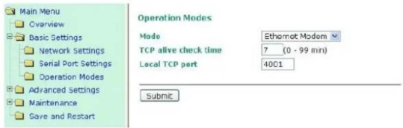
Dial-in
The MiiNePort listens for a TCP/IP connection request from the remote Ethernet modem or host. The MiiNePort's response depends on the ATSO value, as outlined below.
ATS0=0 (default)
The MiiNePort will temporarily accept the TCP connection and then send the RING signal out through the serial port. The serial controller must reply with ATA within 2.5 seconds to accept the connection request, after which the MiiNePort enters data mode. If the ATA command is not received, the MiiNePort will disconnect after sending three RING signals.
ATS0≥1
The MiiNePort will accept the TCP connection immediately and then send the CONNECT
Dial-out
The MiiNePort accepts the AT command ATD
Disconnection request from local site
When the MiiNePort is in data mode, the user can drive the DTR signal to OFF, or send +++ from the local serial port to the MiiNePort. The MiiNePort will enter command mode and return NO CARRIER via the serial port, and then input ATH to shut down the TCP connection after 1 second.
NOTE
The +++ command cannot be divided. The "+" character can be changed in register S2, and the guard time, that prefixes and suffixes the +++ in order to protect the raw data can be changed in register S12.
Disconnection request from remote site
After the TCP connection has been shut down by the remote Ethernet modem or PC, the MiiNePort will send the NO CARRIER signal via the serial port and then return to command mode.
AT Commands
The MiiNePort supports the following common AT commands used with a typical modem:
| No. | AT command | Description | Remarks |
| 1 | ATA | Answer manually | |
| 2 | ATD: | Dial up the IP address: Port No. | |
| 3 | ATE | ATE0=Echo OFFATE1=Echo ON (default) | |
| 4 | ATH | ATH0=On-hook (default)ATH1=Off-hook | |
| 5 | ATI, ATI0, ATI1, ATI2 | Modem version | reply "OK" only |
| 6 | ATL | Speaker volume option | reply "OK" only |
| 7 | ATM | Speaker control option | reply "OK" only |
| 8 | ATO | On line command | |
| 9 | ATP, ATT | Set Pulse/Tone Dialing mode | reply "OK" only |
| 10 | ATQ0, ATQ1 | Quiet command (default=ATQ0) | |
| 11 | ATSr=n | Change the contents of S register | See "S registers" |
| 12 | ATSr? | Read the contents of S register | See "S registers" |
| 13 | ATV | Result code typeATV0 for digit codeATV1 for text code0=OK1=connect (default)2=ring3=No carrier4=error | |
| 14 | ATZ | Reset (disconnect, enter command mode and restore the flash settings) | |
| 15 | AT&C | Serial port DCD control AT&C0=DCD always on AT&C1=DTE detects connection by DCD on/off (default) | |
| 16 | AT&D | Serial port DTR control AT&D0=recognize DTE always ready AT&D1, AT&D2=reply DTE when DTR On (default) | |
| 17 | AT&F | Restore manufacturer's settings | |
| 18 | AT&G | Select guard time | reply "OK" only |
| 19 | AT&R | Serial port RTS option command | reply "OK" only |
| 20 | AT&S | Serial port DSR control | reply "OK" only |
| 21 | AT&V | View settings | |
| 22 | AT&W | Write current settings to flash for next boot up |
S Registers
| No. | S Register | Description & default value | Remarks |
| 1 | S0 | Ring to auto-answer (default=0) | |
| 2 | S1 | Ring counter (always=0) | no action applied |
| 3 | S2 | Escape code character (default=43 ASCII “+”) | |
| 4 | S3 | Return character (default=13 ASCII) | |
| 5 | S4 | Line feed character (default=10 ASCII) | |
| 6 | S5 | Backspace character (default= 8 ASCII) | |
| 7 | S6 | Wait time for dial tone (always=2, unit=sec) | no action applied |
| 8 | S7 | Wait time for carrier (default=3, unit=sec) | |
| 9 | S8 | Pause time for dial delay (always=2, unit=sec) | no action applied |
| 10 | S9 | Carrier detect response time (always=6, unit 1/10 sec) | no action applied |
| 11 | S10 | Delay for hang up after carrier (always=14, unit 1/10 sec) | no action applied |
| 12 | S11 | DTMF duration and spacing (always=100 ms) | no action applied |
| 13 | S12 | Escape code guard time (default=50, unit 1/50 sec), to control th idle time for “+++” |
TCP alive check time
| Setting | Factory Default | Necessity |
| 0 to 99 min | 7 min | Required |
0 min: The TCP connection is not closed due to an idle TCP connection.
1 to 99 min: The module automatically closes the TCP connection if there is no TCP activity for the given time. After the connection is closed, the module starts listening for another host's TCP connection.
Local TCP port
| Setting | Factory Default | Necessity |
| 1 to 65535 | 4001 | Required |
The Local TCP port is the TCP port that the MiiNePort uses to listen to connections, and that other devices must use to contact the MiiNePort. To avoid conflicts with well known TCP ports, the default is set to 4001.
MCSC Mode
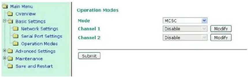
After selecting MCSC mode, you will be able to configure Channel 1 and Channel 2. MCSC mode is designed so that the two channels work independently. Click the Modify button of a channel to update the channel's configuration. We use Channel 1 to illustrate.
Operation Modes
Channel 1
Mode
Real COM
TCP alive check time
7 (0 - 99 min)
Max connection
1
Ignore jammed IP
Enable Disable
Allow driver control
- Enable ○ Disable
Data Packing
Packet length
0 (0 - 1024)
Delimiter 1
00 (Hex) Enable
Delimiter 2
00 (Hex) Enable
Delimiter process
Do nothing
Force transmit
0 (0 - 65535 ms)
Submit
All of the configuration items shown in the above screenshot have been discussed earlier in this chapter. Use the Mode drop-down list to select the operation mode for the channel, and then update the configuration items. When you click Submit, the following confirmation window will appear.
Operation Modes Settings OK!
Close
Click the Close button to return to the initial Operation Modes configuration screen (shown below). At this point you can click the Modify button for Channel 2 to configure the settings for that channel. The configuration settings for Channel 1 will be shown, but you are free to update each configuration item. When you click Submit, the configuration will be saved to the MiiNePort's memory, and will not be erased until the next time you change the configuration.
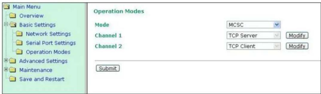
Click Modify to configure Channel 2. For example, if you want to set Channel 2 to Real COM mode, you need to finish your Real COM settings and then click Submit.
Operation Modes Settings OK!
Your changes have been submitted but not saved. Click Save/Restart to save your changes and reboot the server. Your changes will take effect when the server restarts. If you would like to make additional changes, remember to save your configuration before restarting the server.

When the confirmation screen appears, choose either Save/Restart to activate the changes you've made or Close to do other configurations.
For details on MCSC's functionality and configuration, refer to Chapter 8: NetEZ Technologies' MCSC. MCSC is only supported on the MiiNePort E2.
Advanced Settings
Accessible IP List
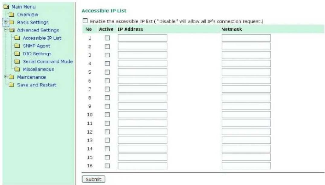
The Accessible IP List allows you to configure the following types of accessibility:
• To allow access to a specific IP address
Enter the IP address in the corresponding field; enter 255.255.255.255 for the netmask.
• To allow access to hosts on a specific subnet
For both the IP address and netmask, use 0 for the last digit (e.g., 192.168.1.0 and 255.255.255.0).
• To allow unrestricted access
Deselect the Enable the accessible IP list option.
Refer to the following table for more configuration examples.
| Allowed Hosts | Entered IP address/Netmask |
| Any host | Disable |
| 192.168.1.120 | 192.168.1.120 / 255.255.255.255 |
| 192.168.1.1 to 192.168.1.254 | 192.168.1.0 / 255.255.255.0 |
| 192.168.0.1 to 192.168.255.254 | 192.168.0.0 / 255.255.0.0 |
| 192.168.1.1 to 192.168.1.126 | 192.168.1.0 / 255.255.255.128 |
| 192.168.1.129 to 192.168.1.254 | 192.168.1.128 / 255.255.255.128 |
SNMP Agent
To enable the SNMP agent function, click the Enable option located to the right of SNMP under Configuration.
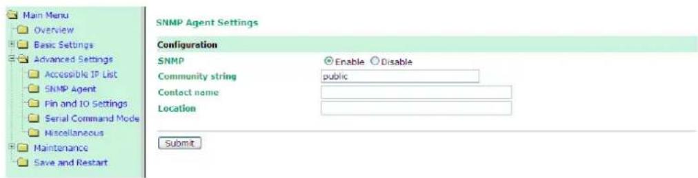
Community string
| Setting | Factory Default | Necessity |
| 1 to 39 characters(E.g., support,886-89191230 #300) | Public | Optional |
A community name is a plain-text password mechanism that is used to authenticate queries to agents of managed network devices.
Contact Name
| Setting | Factory Default | Necessity |
| 1 to 39 characters(E.g., support,886-89191230 #300) | None | Optional |
The SNMP contact information usually includes an emergency contact name and telephone or pager number.
Location
| Setting | Factory Default | Necessity |
| 1 to 39 characters(E.g., floor 1, office 2) | None | Optional |
Enter a location string for SNMP agents. This string is usually set to the street address where the module is physically located.
DIO Settings
The DIO channel is configured on the DIO Settings page. DIO commands can be used to control and obtain data from the module's DIO channels. When digital input operation is selected, the channel's status is controlled by an external digital switch. When digital output operation is selected, the channel transmits a high or low signal.
Refer to Appendix D: DIO Commands for additional information.
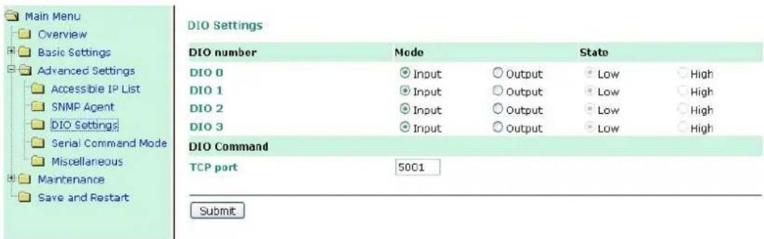
DIO number → Mode
Select Input or Output under Mode to specify digital input or digital output operation.
DIO number → State
Select Low or High under State to specify a high or low state for digital output channels. Note that when Mode is set to Input (as shown in the above screenshot), the State option is deactivated.
DIO Command → TCP port
Select an appropriate TCP port under DIO Command to indicate the port number that will be reserved for DIO commands.
Serial Command Mode (SCM)
SCM (Serial Command Mode) uses serial communication between the MiiNePort and your device's main system to configure the MiiNePort. The configuration is usually done while the device is operating. For more details about SCM commands, see Chapter 8: NetEZ Technologies.
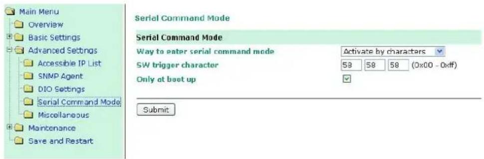
Way to enter serial command mode
| Setting | Factory Default | Necessity |
| Disable,H/W control pin (DIO1),Activate by characters,Activate by break signal | Activate by characters (Only at boot up) | Required |
There are three ways to access SCM:
H/W control pin (DIO 1): Access SCM by pulling JP3 Pin4, the DIO1, to "low."
Activate by characters: Access SCM by sending the MiiNePort's configurable three characters from your device's main system. Check the Only at boot up check box if you would like this action to only be effective when the MiiNePort is booting up.
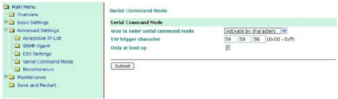
Activate by break signal: Break signals are created by sending continuous Spacing values (i.e., no Start or Stop bits). The absence of an electric signal on the data circuit is interpreted as a Break signal. The Break signal must be of duration longer than the time it takes to send a complete byte plus Start, Stop, and Parity bits.
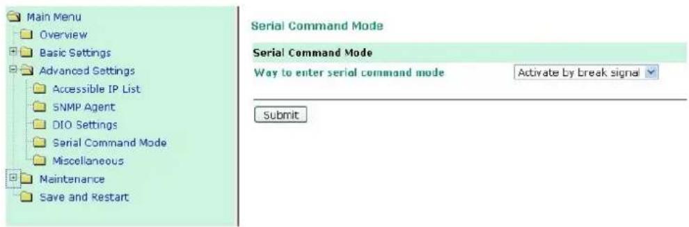
Miscellaneous
PHY Speed, Gratuitous ARP, and Auto IP Report are configured in the Miscellaneous section under Advanced Settings.
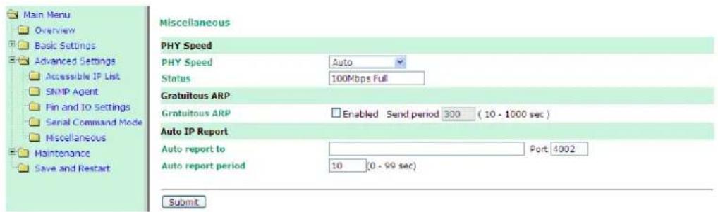
PHY Speed
PHY Speed
| Setting | Factory Default | Necessity |
| Auto | Auto | Required |
Status
| Setting | Factory Default | Necessity |
| 100 Mbps Full Duplex, 100 Mbps Half Duplex, 10 Mbps. Full Duplex, 10 Mbps Half Duplex | Required |
You can set PHY speed to Auto, 100 Mbps Full Duplex, 100 Mbps Half Duplex, 10 Mbps Full Duplex, or 10 Mbps Half Duplex.
Gratuitous ARP
For some applications, you may want the MiiNePort to send broadcast packets to update the ARP table on the server. If you enable this function, the MiiNePort will send broadcast packets periodically based on the specified time interval.
Auto IP Report
When the MiiNePort is used in a dynamic IP environment, additional time must be spent on IP management tasks. For example, when a module is operating as a server (TCP Server or UDP operation modes), a PC operating as a client will need to know the module's IP address. If the DHCP server assigns a new IP address to the module, the PC must have some way of obtaining the module's new IP address. The IP Address report fields are used to set up periodic reporting of the module's IP address when the module's IP address is assigned by a server. The IP address report is sent automatically at regular intervals to the IP address and TCP port number that you specify. Auto IP Report allows you to view the module's IP address report on a PC:
To develop software that parses the IP address report data, see Appendix C: Auto IP Report Protocol for details.
Auto report to
| Setting | Factory Default | Necessity |
| E.g., 192.168.1.1 or URL (IP addresses of the form x.x.x.0 and x.x.x.255 are invalid.) | None | Optional |
Auto report to TCP port
| Setting | Factory Default | Necessity |
| E.g., 4001 | 4002 | Optional |
If left blank, auto IP reporting is disabled. If an IP address is entered along with a TCP port number, the IP address reports will be sent to the specified address and port number.
Auto report period
| Setting | Factory Default | Necessity |
| Time interval (in seconds) | 10 | Optional |
The Auto report period field specifies how often the module will report its IP address. For example, if the auto report period is set to 10 seconds, an IP address report will be sent every 10 seconds.

ATTENTION
The module will send IP address reports only when assigned an IP address from a DHCP or BOOTP server. If a connection to a DHCP or BOOTP server is not available, IP address reports will not be sent.
Maintenance
Console Settings
You can enable or disable the Web, Telnet, and Utility console functions on the Console Settings page. In addition, you can configure the port numbers for the web Telnet servers.
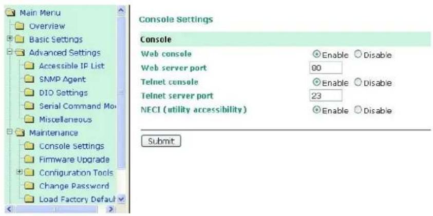
Firmware Upgrade
The MiiNePort's firmware can be upgraded though the web console, or through the NPort Search utility. If you have made any changes to your configuration, remember to save the configuration first before upgrading the firmware. Refer to the Save Configuration section in this chapter for more information. Any unsaved changes will be discarded when the firmware is upgraded. To upgrade the firmware, simply enter the file name and click
Submit. The latest firmware can be downloaded from Moxa's website at www.moxa.com.
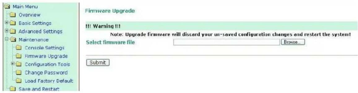
Configuration Tools
The MiiNePort's Auto Configuration, Configuration Import, and Configuration Export functions from the Maintenance → Configuration Tool sub-menu.
Auto Configuration
You can enable or disable AutoCFG from the Auto Configuration page. AutoCFG is designed for enabling automatic network configuration during the production of your device. AutoCFG allows you to realize true device mass production without needing to set up the network modules one by one.
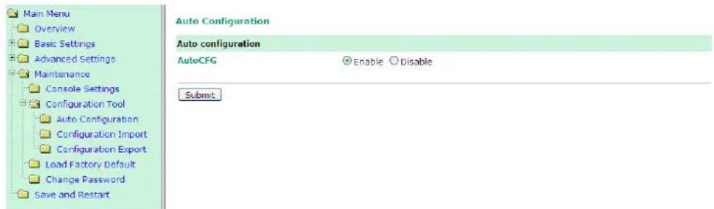
For more information about AutoCFG, refer to Chapter 8: NetEZ Technologies.
Configuration Import
Configuration Import allows you to select a configuration .txt file (e.g., MiiNePortE2.txt) and then import it to instantly the MiiNePort, giving you an efficient way of copying the same configuration to multiple MiiNePort modules. The Configuration Import utility allows you to choose whether to import the IP configuration at the same time.
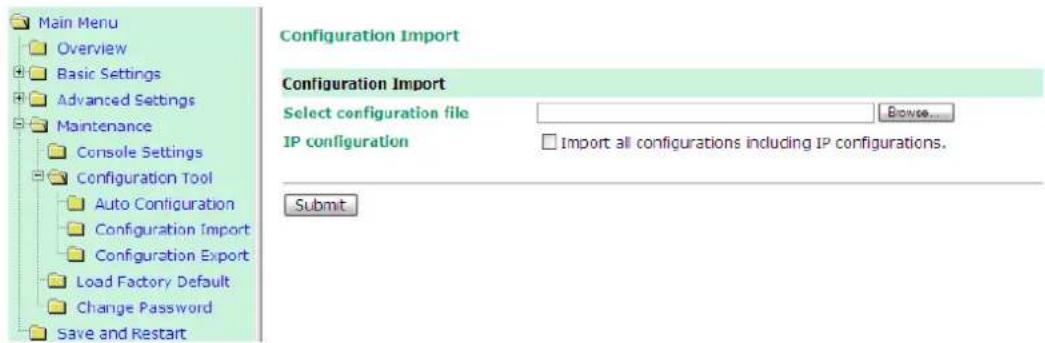
Configuration Export
Configuration Export allows you to export the current configuration to a text file. The exported configuration file, named MiiNePortE2.txt (or MiiNePortE2-H.txt, MiiNePortE3.txt, MiiNePortE3-H.txt) by default, can be imported into another MiiNePort module later with the Configuration Import utility. It can also be used with AutoCFG for mass configuration deployment during your device's mass production stage.
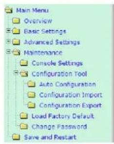
Configuration Export
Configuration Export
Download
Change Password
Click on Change Password in the navigation panel to display the Change Password window.
Change Password
Password
Old password
New password
Confirm password
Submit

Enter the old password and new password (twice) and then click Submit. To remove password protection, just enter the old password and leave the new password blank.
Load Factory Default
To load the factory default settings, click on Load Factory Default in the navigation panel and then click Submit. All previous modifications will be lost, but you can choose to keep the IP settings by checking the Keep IP settings checkbox.
Load Factory Default
Click on Submit to reset all settings, including the console password, to the factory default values.
Reset to Factory Default
√ Keep IP settings
Submit
This chapter introduces EZPower, SCM (Serial Command Mode), AutoCFG (Auto Configuration), and EZPage, the four innovative functions of the NetEZ technology family.
The following topics are covered in this chapter:
EZPower
□ SCM (Serial Command Mode)
□ AutoCFG (Auto Configuration)
☐ MCSC (Multiple Channel Serial Communication)
Command Packets
➢ SCM (Serial Command Mode) under MCSC
□ EZPage
How to Clean up EZPage in MiiNePort
EZPower

The EZPower function makes it easy to configure the MiiNePort's input voltage. Use EZPower to configure the MiiNePort's system power input to either 3.3 VDC or 5 VDC.
SCM (Serial Command Mode)
The MiiNePort's SCM (Serial
Command Mode) utility allows the module's parameters to be retrieved or configured through the serial port, rather than over the network. This is done through the use of specially parsed commands sent to the module through its serial port.

flowchart
graph TD
    A["CPU"] -->|Data| B["MiINePort"]
    B -->|Data| C["SCM"]
    C -->|Data| D["Data"]
    D -->|Data| E["TCP/IP"]
    E --> F["Computer"]
SCM is often used when your device has already been used in actual applications and you need to change the MiiNePort's configuration, such as changing the device's IP address by using your device's key pad.
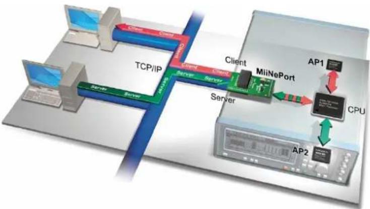
flowchart
graph TD
    subgraph TCP/IP
        A["Client"] --> B["MiiNePort"]
        C["Server"] --> B
        B --> D["CPU"]
        B --> E["AP1"]
        E --> F["AP2"]
    end
    subgraph Server
        G["Server"] --> H["MINePort"]
        I["Client"] --> J["MiiNePort"]
        K["Server"] --> L["MINePort"]
        M["Server"] --> N["MINePort"]
        O["Server"] --> P["MINePort"]
        Q["Server"] --> R["MINePort"]
    end
    style TCP/IP fill:#f9f,stroke:#333
    style Server fill:#ccf,stroke:#333
    style CPU fill:#cfc,stroke:#333
    style Server fill:#fcc,stroke:#333
    style AP1 fill:#ffc,stroke:#333
    style AP2 fill:#fcc,stroke:#333
Refer to Chapter 7: Web Console Configuration for the most appropriate way to use SCM for your application.
Refer to Appendix A: Introduction to SCM (Serial Command Mode) Command Set for detailed instructions on using SCM commands.
AutoCFG (Auto Configuration)
The MiiNePort's AutoCFG function is designed to allow users to realize true mass production. With AutoCFG, you no longer need to configure network modules one by one during the device manufacturing process. To use AutoCFG, follow the steps described below:
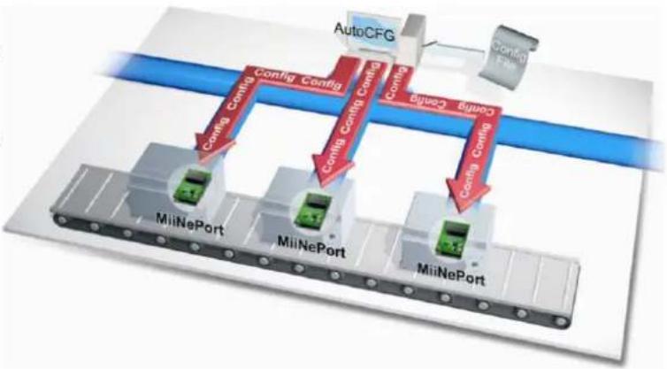
flowchart
graph TD
    A["AutoCFG"] -->|Config Config| B["MiiNePort"]
    A -->|Config Config| C["MiiNePort"]
    A -->|Config Config| D["MiiNePort"]
    B -->|Config Config| E["MiiNePort"]
    C -->|Config Config| F["MiiNePort"]
    D -->|Config Config| G["MiiNePort"]
    E --> H["Output"]
    F --> H
    G --> H
    style A fill:#f9f,stroke:#333
    style B fill:#ccf,stroke:#333
    style C fill:#ccf,stroke:#333
    style D fill:#ccf,stroke:#333
    style E fill:#cfc,stroke:#333
    style F fill:#cfc,stroke:#333
    style G fill:#cfc,stroke:#333
NOTE AutoCFG is enabled by default. If you want to disable AutoCFG, see the Maintenance → Configuration Tool → Auto Configuration in Chapter 7: Web Console Configuration.
Step 1: Export the configuration (see the Configuration → Maintenance → Configuration Tool → Configuration Export section in Chapter 7: Web Console). After you export your configuration, save the configuration to MiiNePort.txt, which contains all of the MiiNePort module's settings.
Step 2: Set up a TFTP server on the network. The TFTP server is used to handle the AutoCFG task on your device production line. Set your TFTP server's IP address to 169.254.x.x/16. Next, save the previously saved MiiNePort.txt file under the root directory of the TFTP server. At this point, the AutoCFG working environment should be ready.
NOTE Many freeware programs for creating TFTP servers can be found on the Internet.
Step 3: AutoIP protocol will automatically assign a temporary IP address to your MiiNePort modules.
Step 4: Your MiiNePort modules will actively send out a broadcast packet asking if there is a TFTP server on the same subnet that has a file named MiiNePortE2.txt (the file name will reflect the device module in use, e.g. MiiNePortE2-H.txt or MiiNePortE3.txt).
Step 5: Your TFTP server will respond to the broadcast packet and your MiiNePort modules will automatically download the MiiNePortE2.txt from the TFTFP server.
Step 6: Your MiiNePort modules will import and save the configuration. Once the MiiNePort finishes the self-configuration process; the MiiNePort's ready LED on your design board will blink. When you see the LED blinking, the AutoCFG task is complete and you can restart or power off your device.
| LED Name | Color | Description |
| Ready | Green, Blinking every 1 sec. | Auto Config complete. |
Step 7: When you need to change the configuration, complete the revised configuration, export the new MiiNePortE2.txt, and save the file to the TFTP server. Choose to replace the original MiiNePortE2.txt located in the root directory. Your MiiNePort modules will then be able to retrieve the revised configuration file.

ATTENTION
Check the following if AutoCFG is not working properly on your device:
- Make sure the AutoCFG function is enabled (the function is enabled by default).
- Check to see if the TFTP Server is working properly.
- Make sure the specific configuration filename is correct: MiiNePortE2.txt, or whichever is appropriate for your device.

ATTENTION
There is no theoretical limit to the number of MiiNePort E2 modules that can be connected at the same time to one subnet for conducting an AutoCFG task.

ATTENTION
Even if you do not want to use the auto configuration function, the module will still go through the process of searching for the MiiNePort E2.txt file on the network every time it starts up if you do not disable the AutoCFG function on your MiiNePort E2. The MiiNePort E2 will resume normal operation if it cannot find which network TFTP server the file is stored on. On average, it will take less than 5 seconds to conduct a search. Your MiiNePort E2 will work properly with its original configuration even if it does not complete the AutoCFG task.

ATTENTION
If you do not want the AutoCFG function to remain active after you've successfully finished the auto-configuration, we suggest that you DISABLE the AutoCFG function when you are creating your MiiNePortE2.txt file, since doing so will prevent the AutoCFG activity from occurring the next time your device is powered on. Refer to Chapter 7: Web Console Configuration for configuration details.
MCSC (Multiple Channel Serial Communication)
NOTE
MCSC is only supported in the MiiNePort E2
The Motivation Behind MCSC
An embedded device server only provides a limited number of physical serial ports to communicate with the device's main system. As a result, users with one physical serial port are generally limited to a single application. If you want to implement multiple serial-to-Ethernet applications (keep in mind that the MiiNePort E2 has only one physical serial port), additional physical serial ports will be needed. Unfortunately, providing
additional physical serial ports increases hardware costs. Moxa's MiiNePort E2's MCSC is designed to solve this dilemma. MCSC (Multiple Channel Serial Communication) is a lightweight, pure software solution that enables multiple serial-to-Ethernet applications all through one physical serial port, without any incremental hardware costs. In short, MCSC allows multiple application channels to share a single physical serial port at the same time.
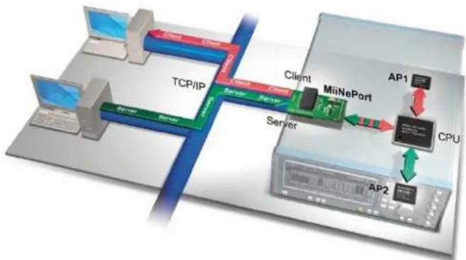
flowchart
graph TD
    A["Computer"] -->|TCP/IP| B["Server"]
    B --> C["Client"]
    C --> D["MiiNePort"]
    D --> E["AP1"]
    D --> F["CPU"]
    D --> G["AP2"]
    style A fill:#f9f,stroke:#333
    style B fill:#ccf,stroke:#333
    style C fill:#cfc,stroke:#333
    style D fill:#fcc,stroke:#333
    style E fill:#cff,stroke:#333
    style F fill:#ffc,stroke:#333
    style G fill:#fcc,stroke:#333
Communication Model
In traditional serial communication models, communication is accomplished by connecting two devices over a single serial channel. At the embedded device server end, Operating Mode (OP Mode) enables the other end of the serial channel to transmit or receive data from the network. However, only one application, TCP Server transportation, TCP Client transportation, or UDP transportation is supported at a time. The communication model is depicted in the figure below.
NOTE
Refer to Chapter 3: Choosing the Proper Operation Mode for an introduction to the operation modes supported by the MiiNePort E2.
Although there are UARTs and even an OS and driver stacks between the TCP Server Application and Controller Application, the applications are considered to be connected by a logical bi-directional channel indicated in red in the following figure:
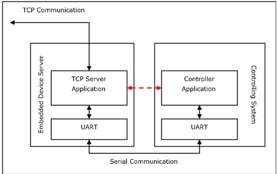
flowchart
graph TD
    A["TCP Communication"] --> B["TCP Server Application"]
    B <--> C["Embedded Device Server"]
    B <--> D["Controller Application"]
    D <--> E["UART"]
    F["Serial Communication"] --> B
    F --> D
    F --> E
    G["Controlling System"] --> D
    G --> E
When using MCSC, an MCSC "command encoding and decoding software module" is attached to each end of the serial communication line. The software module, which is used primarily for UART applications, compresses the data transmitted by the application through the single physical serial channel, and dispatches the data received from the physical serial channel to the appropriate applications. With the help of the MCSC modules, the two applications at opposite ends are still connected to a logical bi-directional channel, but two or more application pairs can also be connected by separate channels to the same physical serial channel. The communication model is depicted in the following figure:
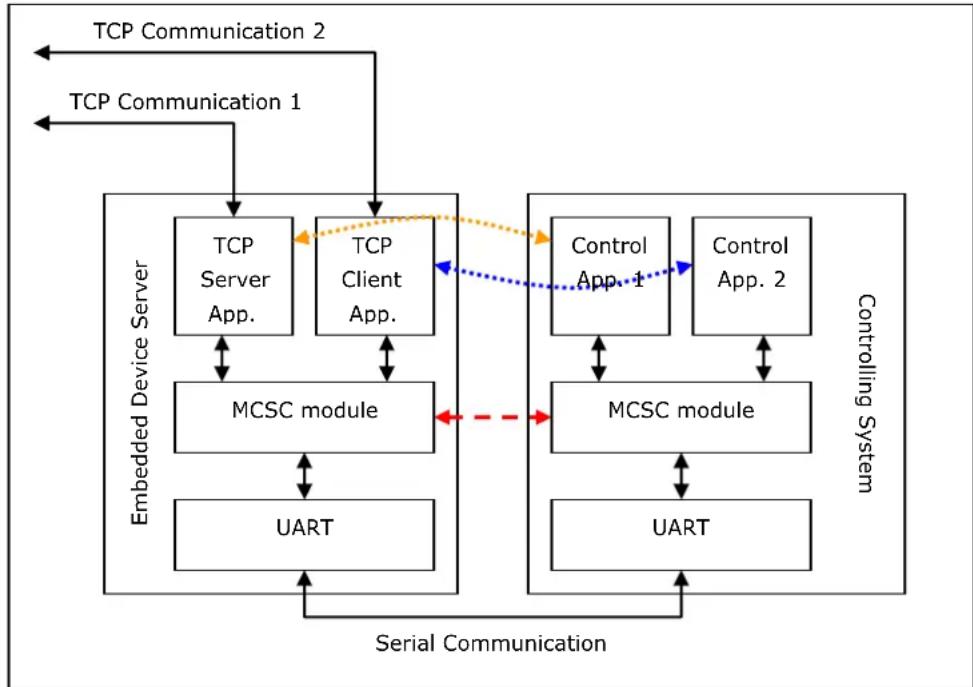
flowchart
graph TD
    A["TCP Communication 1"] --> B["Embedded Device Server"]
    C["TCP Communication 2"] --> B
    B --> D["TCP Server App."]
    B --> E["TCP Client App."]
    D <--> F["MCSC module"]
    E <--> G["MCSC module"]
    F <--> H["UART"]
    G <--> I["UART"]
    J["Control App. 1"] --> K["MCSC module"]
    L["Control App. 2"] --> M["MCSC module"]
    K <--> N["Serial Communication"]
    M <--> N
    style A fill:#f9f,stroke:#333
    style C fill:#f9f,stroke:#333
    style J fill:#ccf,stroke:#333
    style L fill:#ccf,stroke:#333
    style B fill:#dfd,stroke:#333
    style E fill:#dfd,stroke:#333
    style F fill:#dfd,stroke:#333
    style G fill:#dfd,stroke:#333
    style H fill:#dfd,stroke:#333
    style I fill:#dfd,stroke:#333
The MCSC module is built into the MiiNePort E2. To enable MCSC, you need to set your MiiNePort E2 serial port operation mode to MCSC mode and then set the channels' operation modes individually according to your application. In addition, you also need to implement the MCSC module in your device's main system.
The following basic principles apply to all MCSC module implementations.
- MCSC uses a command-based stream protocol. That is, transmissions that do not fit the MCSC command format are treated as application data. All MCSC commands begin with ASCII DLE characters. For the detailed command format, refer to the Command Packets section in following section.
- Other than dealing with MCSC commands, an MCSC module simply transfers application data from the upper application channel to the underlying physical serial channel, and vice versa.
- As with traditional serial applications, MCSC modules are logically connected to a bi-directional channel. To use the serial bandwidth more effectively, MCSC modules separate it into two uni-directional channels. Each MCSC module maintains its transmission application channel and reception application channel. That is, the transmission channel of one end is the reception channel of another.
- Although logically all upper application channels share one physical serial port, to prevent confusion only one channel can be connected to the physical serial port. That is, the application channel connected to the transmission channel is called the active transmission channel, which transmits data to the serial channel. The application channel connected to the reception channel is called the active reception channel, which receives data from the serial channel.
- An MCSC module decides which channel will be the active transmission channel. In other words, the active reception channel is determined by the other MCSC module on the other end of the serial communication channel.
- To avoid data loss, we recommend that you activate serial communication flow control when using MCSC.
Command Packets
An MCSC control packet begins with an ASCII DLE (Data Link Escape, 0x10) character. One end of the serial communication line (normally, an MCSC module) treats the DLE it receives as a special delimiter that indicates the other end of the serial communication line (normally, another MCSC module) that attempts to query or change the MCSC behavior.
If a serial communication end wants to send a 0x10 (DLE) data byte, it sends two DLEs, one after the other. The receiving end decodes these two DLEs into a single 0x10 byte.
Currently, 4 kinds of control packets are defined under MCSC:
Channel Switch Command
| DLE0x10 | SOH0x01 | CHN0x?? |
This command is used for an end to switch its active transmission channel. The CHN field indicates the new channel number. Note that the CHN index is zero based, so you will need to use 0x00 for CHN to switch to channel 1, 0x01 to switch to channel 2, and so on. For safety reasons, if one serial communication end receives a Channel Switch Command that switches to a channel it does not support, it will simply discard it after the data has been transmitted.
Note that when you begin using MCSC, both active communication channels are assumed to be channel 1. After serial communication has ended, data is transferred without directing Channel Switch Command to the channel 1 application.
In the MiiNePort E2, SCM will always be enabled when MCSC is enabled. A special channel indexed as 0xFF in MCSC is dedicated for SCM. For more information, refer to the Serial Command Mode section in this chapter.
Example
| A> | 10 | 01 | 01 | 11 | 22 | 33 | 10 | 01 | 00 | 44 | ||||||
| B> | 10 | 01 | 01 | 33 | 22 | 11 | ||||||||||
| A> | 55 | 66 | ||||||||||||||
| B> | 11 | 22 | 33 | 10 | 01 | 00 | 66 | 55 | 44 | 44 | 55 | 66 |
This example shows that end A sends 3 bytes of data (11, 22, 33) using channel 1 and 3 bytes of data (44, 55, 66) using channel 2. On the other side, end B sends 6 bytes of data (33, 22, 11, 11, 22, 33) using channel 1 and 6 bytes of data (66, 55, 44, 44, 55, 66) using channel 2.
Channel Enquiry Command
| DLE0x10 | ENQ0x05 |
This command is used for an end to query for its active reception channel. By receiving this command, the other end will resend a Channel Switch Command to indicate the active transmission channel it is dealing with, which is the active reception channel the initiator of Channel Enquiry Command deals with.
Example
This examples shows that end A queries for the active transmission channel of end B, and end B replies for channel 2 and then continues to sending 3 bytes of data (11, 22, 33) using channel 2.
| A> | 10 | 05 | |||||||||||||
| B> | 10 | 01 | 01 | 11 | 22 | 33 |
Data Escape Command
| DLE0x10 | DLE0x10 |
Although this is not actually an MCSC command, since the DLE character is used by MCSC to escape its commands, a pair of DLEs will be transmitted to indicate a single 0x10 character of data.
Example
This examples show end A sending 10 bytes of data (00, 02, 04, 06, 08, 0A, 0C, 0E, 10, 12) using channel 1.
| A> | 10 | 01 | 00 | 00 | 02 | 04 | 06 | 08 | 0A | 0C | 0E | 10 | 10 | 12 | ||
| B> |
Abnormal Packets
| DLE0x10 | OTHER??? |
Once the MiiNePort E2 receives a data stream with a header DLE character followed by characters that are not SOH, ENG, or DLE characters, the MiiNePort E2 will see this as an abnormal data packet caused by communication problems and will drop this data packet without sending data out through the Ethernet port. The MiiNePort E2 will return the channel inquiry command (10 05) to the main serial system through the serial channel, helping the main system to detect and troubleshoot the problem.
SCM (Serial Command Mode) under MCSC
When MCSC is enabled, a special application channel indexed as 0xFF (channel 256) is dedicated for Moxa SCM without additional configuration required. SCM enables the controlling system to configure, monitor, or control the attached embedded device server. For more information about what SCM can do, refer to Chapter 3: Choosing the Configuration Tool.
With MCSC, normal network communication continues uninterrupted when the controlling system is monitoring or diagnosing the embedded device server with SCM, providing SCM with greater flexibility.
EZPage
The MiiNePort's EZPage is designed for creating a customized web page to match specific control/monitor requirements of the serial device via web browser. The MiiNePort creates a built-in web server running with Java applet support that can be used to develop customized web pages on the MiiNePort.
EZPage is a java applet based program and you can refer or modify Moxa's web console example to develop specified web console easily. The main entry point of this program is in "src\jar\EZPage.java". EZPage utilizes Moxa's proprietary NECI protocol to control and modify the configurations.
- To browse a customized web console you need to upload your own EZPage to the MiiNePort. Detailed steps are given in the following section.
- The hyper link http://Device's IP/index.htm specifies the location of EZPage content, and is the first entry point for users to access the MiiNePort's web console. MiiNePort will redirect the Moxa default web consoles to http://Device's ip/moxa/home.htm. If a customized web page does not exist, the MiiNePort's default web console will be shown.

ATTENTION
- EZPage supports a maximum packed file size of 512 KB.
- The EZPage example is compiled with JDK V1.6. If necessary, you should re-compile this example with another version of JDK.
Step 1: Compile EZPage
You can compile all *.java files in the src\jar directory one-by-one, or use src\jar\compile.bat to complete the task.
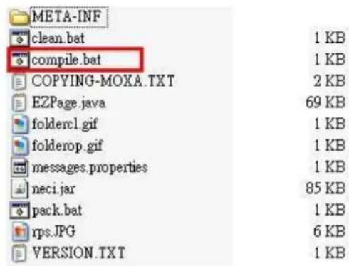
Execute compile.bat. If you experience any problems compiling this example, make sure the version of the compiler you are using is correct.
set COMPLIER_VER-1.6
javac -target %COMPLIER_VER% com\moxa\library\mxci\*.java
javac -target %COMPLIER_VER% com\moxa\library\neci\*.java
javac -target %COMPLIER_VER% *.java
Step 2: Pack EZPage
- You could pack all *.class files in the src\jar directory to a .jar file or use src\jar\pack.bat to pack all *.class files as EZpage.jar.
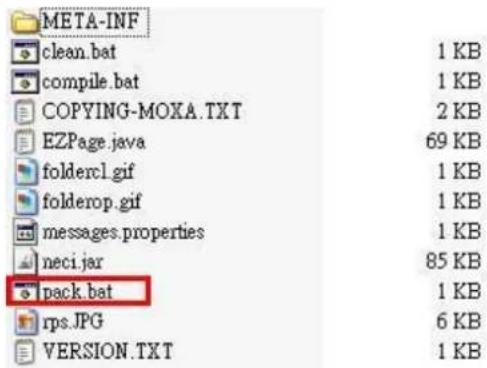
In order to reserve EZPage space for more useful applications, do not pack the source code into the .jar file.
- To delete all *.class files after packing them, issue the following command: src\jar\clean.bat.
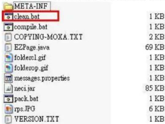
Execute src\jar\clean.bat to delete all *.class files.

ATTENTION
You need to assign the correct target jar file on index.htm
<html>
<applet CODEBASE="ARCHIVE-"ez_page.jar" CODE="ez_page" WIDTH-800 HEIGHT-600>
</applet>
</html>
- Execute the EZPageTool command with the makefs parameter to pack all files in command prompt mode.
Usage: EZPageTool /makefs [file path] [file name]
Example: EZPageTool /makefs c:\jar ezpage
- You will see the following message if the packing process is executed successfully and the packed file can be found in the same directory.
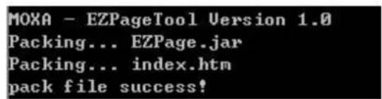
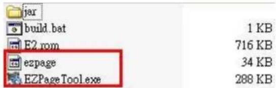
There are three ways to upload EZPage to the MiiNePort.
- EZPageTool:
Execute the EZPageTool command updates parameter to upload EZPage to the MiiNePort in command prompt mode.
Usage: EZPageTool /updatesfs [file to upload] [device IP]
Example: updatefs ezpage 192.168.35.101
You will see the following message if the upload is successful.
- Combine EZPage and MiiNePort's firmware in one file and upload it via the NPort Search Utility: Execute the EZTool command with combine parameter to combine EZPage and firmware in the command prompt mode.
Usage: /combine [file name of EZPage] [file name of firmware] [file name after combination]
Example: /combine ezpage E2.rom e2_ezpage.rom
You will see the following message if the combine process executes successfully.

The file can be found in the same directory.
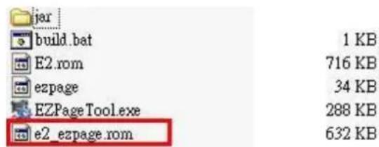
Execute the NPort Search Utility and select the combined firmware file to upload to the MiiNePort.
- Combine EZPage and MiiNePort's firmware as one file and upload it via the MiiNePort's web console:
Log in to the MiiNePort's web console and upgrade the firmware by using combined firmware.
How to Clean up EZPage in MiiNePort
Execute the EZPageTool command with the cleanfs parameter to clean up the EZPage of specified MiiNePort modules in command prompt mode
Usage: /cleanfs [device IP]
Example: /cleanfs 192.168.35.101
You will see the following message if the clean up process executed successfully.
MOXA - EZPageTool Version 1.0 clean file success!
Introduction to SCM (Serial Command Mode) Command Set
The following topics are covered in this appendix:
□ Command/Reply Format
☐ Command Code for Getting the Configuration
☐ Command Code for Setting the Configuration
☐ Command Code for Retrieving Running Configuration
☐ Command Code for Viewing the Status
□ Control Command Code
Command/Reply Format
Single Line Command Format
| Head | Op | Cmd | Parameters | Tail |
| 1 byte | 1 byte | 2 bytes | 0 to n bytes | 1 or 2 bytes |
Single Line Reply Format
| Head | Op | Cmd | Parameters | Tail |
| 1 byte | 1 byte | 2 bytes | 0 to n bytes | 1 or 2 bytes |
Head and Tail
| Head1 byte | Tail1 or 2 bytes | |
| Command | ? | CRLFCR-LF |
| Reply | ! | LF |
Operation Code
| Operation Code | Meaning |
| G | Get configuration from MiiNePort's RAM |
| S | Set configuration to MiiNePort's RAM |
| R | Retrieve running configuration |
| V | View status |
| C | Control |
Status Codes
| Status Code | Meaning |
| E | Enter Serial Command Mode |
| 0 | Command was executed successfully |
| 1 | Unrecognized format |
| 2 | Operation is not valid |
| 3 | Command is not valid |
| 4 | Parameter is incorrect |
| 5 | Parameter is too long |
Restriction
The total number of parameters in a single command cannot exceed 1024 characters.
Command Code for Getting the Configuration
Device Name
Command code: BN
Command parameters: N/A
Reply parameters: MiiNePort's name.
| ?GBN← | System requests configured device name for this MiiNePort. |
| !GBN0MiiNePort_E2_9527← | MiiNePort reports device name as 'MiiNePort_E2_9527' |
Console Password
Command code: BP
Command parameters: N/A
Reply parameters: MiiNePort's console password.
| ?GBP← | System requests console password for this MiiNePort. |
| !GBP01234← | MiiNePort reports console password as '1234'. |
Web console
Command code: BH
Command parameters: N/A
Reply parameters: 1 and web console TCP port separated by a semicolon (;) if web console is enabled, or a 0 if it is disabled.
| ?GBH← | System requests http console setting for this MiiNePort. |
| !GBH01;80← | MiiNePort reports http console as 'Enable' and http port as '80'. |
Telnet console
Command code: BT
Command parameters: N/A
Reply parameters: 1 and telnet console TCP port separated by a semicolon (;) if telnet console is enabled, or a 0 if it is disabled.
| ?GBT← | System requests telnet console setting for this MiiNePort. |
| !GBT01;23← | MiiNePort reports telnet console as 'Enable' and telnet port as '23'. |
Auto configuration
Command code: BA
Command parameters: N/A
Reply parameters: 1 if Auto configuration is enabled, 0 otherwise.
| ?GBA← | System requests Auto configuration setting for this MiiNePort. |
| !GBA01← | MiiNePort reports Auto configuration as 'Enable'. |
NECI (utility accessibility)
Command code: BU
Command parameters: N/A
Reply parameters: 1 if NECI is enabled, 0 otherwise.
| ?GBU← | System requests NECI setting for this MiiNePort. |
| !GBU01← | MiiNePort reports NECI as 'Enable'. |
IP configuration
Command code: NC
Command parameters: N/A
Reply parameters: MiiNePort's IP configuration index as follows.
| 0 | Static |
| 1 | DHCP |
| 2 | DHCP/BOOTP |
| 3 | BOOTP |
| 4 | AUTOIP |
| ?GNC← | System requests IP configuration for this MiiNePort. |
| !GNC00← | MiiNePort reports IP configuration as 'Static'. |
IP address
Command code: NI
Command parameters: N/A
Reply parameters: MiiNePort's IP address.
| ?GNI← | System requests IP address for this MiiNePort. |
| !GNI0192.168.127.254← | MiiNePort reports IP address as '192.168.127.254'. |
Netmask
Command code: NM
Command parameters: N/A
Reply parameters: MiiNePort's Netmask address.
| ?GNM← | System requests Netmask address for this MiiNePort. |
| !GNM0255.255.255.0← | MiiNePort reports netmask as '255.255.255.0'. |
Gateway
Command code: NG
Command parameters: N/A
Reply parameters: MiiNePort's Gateway address.
| ?GNG← | System requests Gateway address for this MiiNePort. |
| !GNG0255.255.255.255← | MiiNePort reports Gateway address as '255.255.255.255'. |
DNS
Command code: ND
Command parameters: The index (1 or 2) of DNS server.
Reply parameters: MiiNePort's DNS address.
| ?GND1← | System requests DNS server 1 address for this MiiNePort. |
| !GND0192.168.1.2← | MiiNePort reports DNS server 1 address as '192.168.1.2'. |
PHY Speed
Command code: NS
Command parameters: N/A
Reply parameters: MiiNePort's PHY speed as follows:
| 0 | PHY auto negotiation is enabled. |
| 10 | PHY speed is forced to 10Mbps with half duplex |
| 11 | PHY speed is forced to 10Mbps with full duplex |
| 100 | PHY speed is forced to 100Mbps with half duplex |
| 101 | PHY speed is forced to 100Mbps with full duplex |
| ?GNS← | System requests PHY speed setting for this MiiNePort. |
| !GNS00← | MiiNePort reports PHY speed determined by PHY auto negotiation function. |
Enable/Disable SNMP
Command code: MS
Command parameters: N/A
Reply parameters: 1 (Enable) or 0 (Disable) MiiNePort's SNMP agent.
| ?GMS← | System requests Enable/Disable SNMP agent for this MiiNePort. |
| !GMS01← | MiiNePort reports SNMP agent as 'Enable'. |
Community String
Command code: MU
Command parameters: N/A
Reply parameters: MiiNePort's SNMP Community string.
| ?GMU← | System requests SNMP community string for this MiiNePort. |
| !GMU0public← | MiiNePort reports SNMP community string as 'public'. |
Contact Name
Command code: MN
Command parameters: N/A
Reply parameters: MiiNePort's SNMP Contact Name.
| ?GMN← | System requests SNMP contact name for this MiiNePort. |
| !GMN0s_name← | MiiNePort reports SNMP contact name as 's_name'. |
Location
Command code: ML
Command parameters: N/A
Reply parameters: MiiNePort's SNMP Location.
| ?GML← | System requests SNMP location for this MiiNePort. |
| !GML0s_location← | MiiNePort reports SNMP location as 's_location'. |
Enable/Disable Accessible IP List
Command code: AS
Command parameters: N/A
Reply parameters: Enable (1) or Disable (0) MiiNePort's accessible IP list.
| ?GAS | System requests Enable/Disable accessible IP list for this MiiNePort. |
| !GAS01← | MiiNePort reports accessible IP list as 'Enable'. |
Accessible IP List
Command code: AI
Command parameters: The index of accessible IP list (from 1 to 16)
Reply parameters: Return format Mode;IP;Netmask in the accessible IP list. If mode equals to 1, it is active, otherwise it is inactive.
| ?GAI1← | System requests 1st accessible IP list for this MiiNePort. |
| !GAI01;192.168.1.2;255.255.255.0← | MiiNePort reports 1st accessible IP list as 'Active', IP address as '192.167.1.2', and Netmask as '255.255.255.0'. |
Auto IP Report
Command code: NR
Command parameters: N/A
Reply parameters: MiiNePort's auto IP report setting.
| ?GNR← | System requests auto IP report for this MiiNePort. |
| !GNR0192.168.1.250:4000;50← | MiiNePort reports Auto IP report server as '192.168.1.250' and port as '4000', and report period as '50'. |
Port alias
Command code: SA
Command parameters: Port index.
Reply parameters: MiiNePort's Port alias.
| ?GSA1← | System requests port 1 alias for this MiiNePort. |
| !GSA0port1← | MiiNePort reports Port alias as 'port1'. |
Baudrate
Command code: SB
Command parameters: Port index.
Reply parameters: MiiNePort's Baudrate.
| ?GSB1← | System requests port 1's Baudrate for this MiiNePort. |
| !GSB0115200← | MiiNePort reports Baudrate as '115200'. |
Data bits
Command code: SD
Command parameters: Port index.
Reply parameters: MiiNePort's Data bits.
| ?GSD1← | System requests port 1's Data bits for this MiiNePort. |
| !GSD08← | MiiNePort reports Data bits as '8'. |
Stop bits
Command code: SS
Command parameters: Port index.
Reply parameters: MiiNePort's stop bits index.
Stop Bits Index Table:
| 0 | Stop bits is 1 |
| 1 | Stop bits is 1.5 |
| 2 | Stop bits is 2 |
| ?GSS1← | System requests port 1's Stop bits for this MiiNePort. |
| !GSS00← | MiiNePort reports Stop bits as '1'. |
Parity
Command code: SP
Command parameters: Port index.
Reply parameters: MiiNePort's Parity index as follows.
| 0 | None |
| 1 | Odd |
| 2 | Even |
| 3 | Mark |
| 4 | Space |
| ?GSP1← | System requests port 1's Parity for this MiiNePort. |
| !GSP00← | MiiNePort reports Parity as 'None'. |
Flow control
Command code: SL
Command parameters: Port index.
Reply parameters: MiiNePort's Flow control index as follows.
| 0 | None |
| 1 | RTS/CTS |
| 2 | XON/XOFF |
| 3 | DTR/DSR |
| ?GSL1← | System requests port 1's Flow control for this MiiNePort. |
| !GSL01← | MiiNePort reports Flow control as 'RTS/CTS'. |
FIFO
Command code: SF
Command parameters: Port index.
Reply parameters: 1 (Enable) or 0 (Disable) MiiNePort's FIFO.
| ?GSF1← | System requests port 1's FIFO for this MiiNePort. |
| !GSF01← | MiiNePort reports FIFO as 'Enable'. |
Interface
Command code: SI
Command parameters: Port index.
Reply parameters: 0 (RS232) or 1 (RS485-2wire) MiiNePort's Interface.
| ?GSI1↓ | System requests for port 1's interface for this MiiNePort. |
| !GSI01↓ | MiiNePort reports interface is 'RS485-2wire'. |
Operation Mode
Command code: OM
Command parameters: Two numbers separated by a semicolon (;) denote port index and MCSC channel index.
For the port itself, channel index is 0.
Reply parameters: MiiNePort's operation mode index as shown in the following table.
| 0 | Disable |
| 1 | Real COM |
| 2 | RFC2217 |
| 3 | TCP server |
| 4 | TCP client |
| 5 | UDP |
| 6 | e-modem |
| 7 | MCSC (This value is unavailable for MCSC channels.) |
| ?GOM1;0↓ | System requests for port 1's Operation Mode for this MiiNePort. |
| !GOM04↓ | MiiNePort reports Operation Mode is 'TCP client'. |
| ?GOM1;2↓ | When port 1 is set to MCSC, system requests for the operation mode for channel 2 of port 1. |
| !GOM02↓ | MiiNePort reports operation mode is `RFC2217'. |
Data Packing Length
Command code: OL
Command parameters: Two numbers separated by a semicolon (;) denote port index and MCSC channel index.
For an MCSC-disabled port, the channel index is 0.
Reply parameters: MiiNePort's data packing length as follows.
| ?GOL1;0← | System requests port 1's data packing length for this MiiNePort. |
| !GOL0256← | MiiNePort reports data packing length as '256'. |
| ?GOL1;2 | When port 1 is set to MCSC, system requests the data packing length for channel 2 of port 1. |
| !GOL0128 | MiiNePort reports data packing length as '128'. |
Delimiter
Command code: OD
Command parameters: Two numbers separated by a semicolon (;) denote port index and MCSC channel index. For an MCSC-disabled port, the channel index is 0.
Reply parameters: MiiNePort's delimiter setting. (delimiter1 enable/disable; hex1; delimiter2 enable/disable; hex2)
| ?GOD1;0← | System requests port 1's delimiter setting for this MiiNePort. |
| !GOD01;10;1;13← | MiiNePort reports delimiter 1 as 'Enable' and hex code as '10', delimiter 2 as 'Enable' and hex code as '13'. |
Delimiter Process
Command code: OT
Command parameters: Two numbers separated by a semicolon (;) denote port index and MCSC channel index.
For an MCSC-disabled port, the channel index is 0.
Reply parameters: MiiNePort's delimiter process.
| 0 | Do nothing |
| 1 | Delimiter+1 |
| 2 | Delimiter+2 |
| 3 | Strip Delimiter |
| ?GOT1;0← | System requests port 1's delimiter process for this MiiNePort. |
| !GOT02← | MiiNePort reports delimiter process as 'Delimiter+2'. |
Force Transmit
Command code: OF
Command parameters: Two numbers separated by a semicolon (;) denote port index and MCSC channel index. For an MCSC-disabled port, the channel index is 0.
Reply parameters: MiiNePort's force transmit timeout.
| ?GOF1;0← | System requests port 1's force transmit timeout for this MiiNePort. |
| !GOF00← | MiiNePort reports force transmit timeout as '0' sec. |
Real COM TCP alive check time
Command code: RA
Command parameters: Two numbers separated by a semicolon (;) denote port index and MCSC channel index. For an MCSC-disabled port, the channel index is 0.
Reply parameters: MiiNePort's TCP alive check time.
| ?GRA1;0← | System requests port 1's TCP alive check time for por 1. |
| !GRA05← | MiiNePort reports TCP alive check time as '5' min. |
Real COM max connection
Command code: RM
Command parameters: Two numbers separated by a semicolon (;) denote port index and MCSC channel index.
For an MCSC-disabled port, the channel index is 0.
Reply parameters: MiiNePort's TCP maximum connection number.
| ?GRM1;1← | System requests maximum connection number for port 1 and channel 1. |
| !GRM04← | MiiNePort reports maximum connection number as '4'. |
Real COM Ignores Jammed IP
Command code: RJ
Command parameters: Two numbers separated by a semicolon (;) denote port index and MCSC channel index.
For an MCSC-disabled port, the channel index is 0.
Reply parameters: 1 (Enable) or 0 (Disable)
| ?GRJ1;2← | System requests jammed IP policy for port 1's channel 2. |
| !GRJ01← | MiiNePort reports ignore jammed IP as 'Enable'. |
Real COM Allows Driver Control
Command code: RD
Command parameters: Two numbers separated by a semicolon (;) denote port index and MCSC channel index.
For an MCSC-disabled port, the channel index is 0.
Reply parameters: 1 (Enable) or 0 (Disable)
| ?GRD1;0← | System requests allow driver control policy for port1. |
| !GRD01← | MiiNePort reports allow driver control as 'Enable'. |
RFC2217 TCP alive check time
Command code: FA
Command parameters: Two numbers separated by a semicolon (;) denotes port index and MCSC channel index. For MCSC-disabled port, channel index shall be 0.
Reply parameters: 1 (Enable) or 0 (Disable)
| ?GFA1;0↓ | System requests for alive check time for port1. |
| !GFA07↓ | MiiNePort reports alive check time is '7'. |
RFC2217 local listen port
Command code: FP
Command parameters: Two numbers separated by a semicolon (;) denotes port index and MCSC channel index.
For MCSC-disabled port, channel index shall be 0.
Reply parameters: local listen port
| ?GFP1;0↓ | System requests for RFC2217 local listen port for port 1. |
| !GFP01234↓ | MiiNePort reports RFC2217 local listen port is '1234'. |
TCP Server Connection Control
Command code: TS
Command parameters: Two numbers separated by a semicolon (;) denote port index and MCSC channel index.
For an MCSC-disabled port, the channel index is 0.
Reply parameters: TCP server connection control as shown in the following table.
| 0 | Always accept |
| 1 | Accept with DSR on |
| ?GTS1;0← | System requests TCP server connection control for port 1. |
| !GTS00← | MiiNePort reports incoming policy as 'Always accept'. |
TCP Alive Check Time
Command code: TA
Command parameters: Two numbers separated by a semicolon (;) denote port index and MCSC channel index.
For an MCSC-disabled port, the channel index is 0.
Reply parameters: TCP alive check time
| ?GTA1;0← | System requests TCP alive check time for port 1. |
| !GTA05← | MiiNePort reports TCP alive check time as '5' minutes. |
TCP Port
Command code: TP
Command parameters: Two numbers separated by a semicolon (;) denote port index and MCSC channel index.
For an MCSC-disabled port, the channel index is 0.
Reply parameters: TCP port
| ?GTP1;0← | System requests TCP port for port 1. |
| !GTP04100← | MiiNePort reports TCP port as '4100'. |
TCP command port
Command code: TO
Command parameters: Two numbers separated by a semicolon (;) denotes port index and MCSC channel index.
For MCSC-disabled port, channel index shall be 0.
Reply parameters: TCP port
| ?GTO1;0↓ | System requests for TCP command port for port 1. |
| !GTO0966↓ | MiiNePort reports TCP command port is '966'. |
TCP server Allow Driver Control
Command code: TD
Command parameters: Two numbers separated by a semicolon (;) denotes port index and MCSC channel index.
For MCSC-disabled port, channel index shall be 0.
Reply parameters: 1 (Enable) or 0 (Disable)
| ?GTD1;0↓ | System requests for allow driver control policy for port1. |
| !GTD01↓ | MiiNePort reports allow driver control is 'Enable'. |
TCP Client Connection Control
Command code: TC
Command parameters: Two numbers separated by a semicolon (;) denotes port index and MCSC channel index.
For MCSC-disabled ports, the MCSC channel index is 0.
Reply parameters: TCP client connection control index as shown in the following table
| 0 | Start up / None |
| 1 | Any character / None |
| 2 | Any character / Inactivity time |
| 3 | DSR On / DSR OFF |
| 4 | DSR On / None |
| 5 | DCD On / DCF OFF |
| 6 | DCD On / None |
| ?GTC1;0← | System requests TCP client connection control for por 1. |
| !GTC01← | MiiNePort for TCP client connection control as 'Any character / None'. |
TCP destination address
Command code: TI
Command parameters: Three numbers separated by a semicolon (;) denote port index, MCSC channel index, and destination address index. For an MCSC-disabled port, the channel index is 0. The destination address index is as follows:
| 0 | Destination address |
| 1 | Alternated address 1 |
| 2 | Alternated address 2 |
| 3 | Alternated address 3 |
Reply parameters: TCP destination address and port
| ?GTI1;0;0← | System requests destination address for port 1. |
| !GTI0192.168.1.2:4001← | MiiNePort reports destination address as '192.168.1.2' and port as '4001'. |
TCP max connection
Command code: TM
Command parameters: Two numbers separated by a semicolon (;) denote port index and MCSC channel index. For an MCSC-disabled port, the channel index is 0.
Reply parameters: MiiNePort's TCP maximum connection number.
| ?GTM1;1↓ | System requests maximum connection number for port 1 and channel 1. |
| !GTM04↓ | MiiNePort reports maximum connection number as '4'. |
TCP ignore jammed IP
Command code: TJ
Command parameters: Two numbers separated by a semicolon (;) denote port index and MCSC channel index. For an MCSC-disabled port, the channel index is 0.
Reply parameters: 1 (Enable) or 0 (Disable)
| ?GTJ1;2← | System requests jammed IP policy for port 1's channel 2. |
| !GTJ01← | MiiNePort reports ignore jammed IP as 'Enable'. |
TCP client local port
Command code: TL
Command parameters: Three numbers separated by semicolons (;) denote port index, MCSC channel index, and local port index. For MCSC-disabled ports, the channel index is 0.
Reply parameters: TCP port.
| ?GTL1;0;0,1 | System requests for TCP client local port setting for port 1. |
| !GTL05002 | MiiNePort reports TCP client local port is 5002. |
TCP inactivity time
Command code: TV
Command parameters: Two numbers separated by a semicolon (;) denote port index and MCSC channel index.
For an MCSC-disabled port, the channel index is 0.
Reply parameters: TCP inactivity time.
| ?GTV1;0← | System requests inactivity time for port 1. |
| !GTV00← | MiiNePort reports inactivity time as '0'. |
UDP destination address
Command code: UD
Command parameters: Three numbers separated by a semicolon (;) denote port index, MCSC channel index, and destination address index from 1 to 4. For an MCSC-disabled port, the channel index is 0.
Reply parameters: Begin address - End address: port
| ?GUD1;0;3← | System requests UDP destination address 3 for port 1 |
| !GUD0192.168.1.3-192.168.1.8:4001← | MiiNePort reports UDP destination address is from '192.168.1.3' to '192.168.1.8' and port as '4001'. |
UDP local listen port
Command code: UP
Command parameters: Two numbers separated by a semicolon (;) denote port index and MCSC channel index. For an MCSC-disabled port, the channel index is 0.
Reply parameters: local listen port
| ?GUP1;0← | System requests UDP local listen port for port 1. |
| !GUP04001← | MiiNePort reports UDP local listen port as '4001'. |
E-modem alive check time
Command code: EA
Command parameters: Two numbers separated by a semicolon (;) denotes port index and MCSC channel index. For MCSC-disabled port, channel index shall be 0.
Reply parameters: TCP alive check time
| ?GEA1;0↓ | System requests for TCP alive check time for port 1. |
| !GEA05↓ | MiiNePort reports TCP alive check time is '5' minutes. |
E-modem local listen port
Command code: EP
Command parameters: Two numbers separated by a semicolon (;) denotes port index and MCSC channel index.
For MCSC-disabled port, channel index shall be 0.
Reply parameters: local listen port
| ?GEP1;0↓ | System requests UDP local listen port for port 1. |
| !GEP04001↓ | MiiNePort reports UDP local listen port is '4001'. |
DIO initial mode
Command code: PM
Command parameters: DIO port index. For the MiiNePort E2, the index is as follows:
| Index | DIO port | MiiNePort E2 PIN number |
| 0 | DIO0 | JP3 - PIN1 |
| 1 | DIO1 | JP3 - PIN4 |
| 2 | DIO2 | JP3 - PIN2 |
| 3 | DIO3 | JP3 - PIN3 |
Reply parameters: 1 (output) or 0 (input); note that for the MiiNePort E2, this configuration is available if a specific PIN function is set to DIO.
| ?GPM1← | System requests DIO1's initial mode for this MiiNePort. |
| !GPM01← | MiiNePort reports DIO1's initial mode as 'output'. |
DIO initial state
Command code: PS
Command parameters: DIO port index. For the MiiNePort E2, the index is as follows:
| Index | DIO port | MiiNePort E2 PIN number |
| 0 | DIO0 | JP3 - PIN1 |
| 1 | DIO1 | JP3 - PIN4 |
| 2 | DIO2 | JP3 - PIN2 |
| 3 | DIO3 | JP3 - PIN3 |
Reply parameters: 1 (high) or 0 (low), note that this function is configuration only if specific DIO port is set to initial output.
| ?GPS0↓ | System requests DIO0's initial state for this MiiNePort |
| !GPS00↓ | MiiNePort reports DIO0's initial state is 'low'. |
Serial command mode trigger
Command code: CT
Command parameters: N/A
Reply parameters: serial command mode trigger index as shown in the following table.
| 0 | Disable |
| 1 | H/W control pin(DIO1) |
| 2 | Activated by characters |
| 3 | Activated by break signal |
Note that this configuration is valid only if port 1's operation mode is not set to MCSC.
| ?GCT← | System requests serial command mode trigger method for this MiiNePort. |
| !GCT01← | MiiNePort reports serial command mode is triggered by DIO1. |
Serial command mode trigger characters
Command code: CC
Command parameters: N/A
Reply parameters: serial command mode trigger characters, in hex, separated by a semicolon (;).
Note that this configuration is valid only if the serial command mode trigger method is set to Activated by characters.
| ?GCC← | System requests serial command mode trigger characters for this MiiNePort. |
| !GCC058;58;58← | MiiNePort reports serial command mode triggered by `XXX' (0x585858). |
Serial command mode triggered only at boot up
Command code: CB
Command parameters: N/A
Reply parameters: 0 if serial command mode can be triggered at any time, or 1 if it can only be triggered at boot up.
Note that this configuration is valid only if the serial command mode trigger method is set to Activated by characters.
| ?GCB← | System requests serial command mode for this MiiNePort. |
| !GCB01← | MiiNePort reports serial command mode can only be triggered by characters at boot up. |
Gratuitous ARP
Command code: VA
Command parameters: N/A.
Reply parameters: 1 and send period if gratuitous ARP is enabled; otherwise, reply 0.
| ?GVA← | System requests gratuitous ARP status for alert mail server. |
| !GVA01;300← | MiiNePort reports gratuitous ARP as 'Enable' and send period as '300' sec. |
Command Code for Setting the Configuration
Device Name
Command code: BN
Command parameters: The new device name for the MiiNePort.
Reply parameters: N/A
| ?SBNMiiNePort@Office← | System sets the device name as 'MiiNePort@Office'. |
| !SBN0← | MiiNePort reports command executed successfully. |
Password
Command code: BP
Command parameters: MiiNePort's console password
Reply parameters: N/A
| ?SBP1234← | System sets console password as '1234' for this MiiNePort. |
| !SBP0← | MiiNePort reports command executed successfully. |
Web console
Command code: BH
Command parameters: 1 and web console TCP port to enable web console, or 0 to disable it.
Reply parameters: N/A
| ?SBH1;80← | System sets http console as 'Enable' and http port as '80' for this MiiNePort. |
| !SBH0← | MiiNePort reports command executed successfully. |
Telnet console
Command code: BT
Command parameters: 1 and telnet console TCP port to enable telnet console, or 0 to disable it.
Reply parameters: N/A
| ?SBT1;23← | System sets telnet console as 'Enable' and telnet port as '23' for this MiiNePort. |
| !SBT0← | MiiNePort reports command executed successfully. |
Auto configuration
Command code: BA
Command parameters: 1 if Auto configuration is enabled, 0 otherwise.
Reply parameters: N/A
| ?SBA1← | System sets auto configuration as 'Enable' for this MiiNePort. |
| !SBA0← | MiiNePort reports command executed successfully. |
NECI (utility accessibility)
Command code: BU
Command parameters: 1 if NECI is enabled, 0 otherwise.
Reply parameters: N/A
| ?SBU1← | System sets NECI setting as 'Enable' for this MiiNePort. |
| !SBU0← | MiiNePort reports command executed successfully. |
IP configuration
Command code: NC
Command parameters: MiiNePort's IP configuration index as shown in the following table
Reply parameters: N/A
| 0 | Static |
| 1 | DHCP |
| 2 | DHCP/BOOTP |
| 3 | BOOTP |
| 4 | AutoIP |
| ?SNC0← | System sets IP configuration as 'Static'. |
| !SNC0← | MiiNePort reports command executed successfully. |
IP address
Command code: NI
Command parameters: MiiNePort's IP address.
Reply parameters: N/A
| ?SNI192.168.1.2← | System sets IP address as '192.168.1.2'. |
| !SNIO← | MiiNePort reports command executed successfully. |
Netmask
Command code: NM
Command parameters: MiiNePort's Netmask address.
Reply parameters: N/A
| ?SNM255.255.255.0← | System sets Netmask as '255.255.255.0'. |
| !SNM0← | MiiNePort reports command executed successfully. |
Gateway
Command code: NG
Command parameters: MiiNePort's Gateway address.
Reply parameters: N/A
| ?SNG192.168.1.254← | System sets Gateway as '192.168.1.254'. |
| !SNG0← | MiiNePort reports command executed successfully. |
DNS
Command code: ND
Command parameters: The index (1,2) and DNS server address, separated by a semicolon (;).
Reply parameters: N/A
| ?SND1;192.168.1.123 | System sets DNS1 as '192.168.1.123'. |
| !SND0 | MiiNePort reports command executed successfully. |
PHY Speed
Command code: NS
Command parameters: N/A
Reply parameters: MiiNePort's PHY speed as follows:
| 0 | PHY auto negotiation is enabled. |
| 10 | PHY speed is forced to 10Mbps with half duplex |
| 11 | PHY speed is forced to 10Mbps with full duplex |
| 100 | PHY speed is forced to 100Mbps with half duplex |
| 101 | PHY speed is forced to 100Mbps with full duplex |
| ?SNS10← | System forces PHY speed to 10Mbps with half duplex. |
| !SNS0← | MiiNePort reports command executed successfully. |
Enable/Disable SNMP
Command code: MS
Command parameters: 1 (Enable) or 0 (Disable) MiiNePort's SNMP agent.
Reply parameters: N/A
| ?SMS1← | System sets SNMP agent as 'Enable'. |
| !SMS0← | MiiNePort reports command executed successfully. |
Community String
Command code: MU
Command parameters: MiiNePort's SNMP Community string.
Reply parameters: N/A
| ?SMUpublic← | System sets SNMP community string as 'public'. |
| !SMU0← | MiiNePort reports command executed successfully. |
Contact Name
Command code: MN
Command parameters: MiiNePort's SNMP contact name.
Reply parameters: N/A
| ?SMNcontact← | System sets SNMP contact name as 'contact'. |
| !SMN0← | MiiNePort reports command executed successfully. |
Location
Command code: ML
Command parameters: MiiNePort's SNMP location.
Reply parameters: N/A
| ?SMLlocation← | System sets SNMP contact name as 'location'. |
| !SML0← | MiiNePort reports command executed successfully. |
Enable/Disable Accessible IP List
Command code: AS
Command parameters: 1 (Enable) or 0 (Disable) MiiNePort's accessible IP list.
Reply parameters: N/A
| ?SAS1← | System sets accessible IP list as 'Enable'. |
| !SAS0← | MiiNePort reports command executed successfully. |
Accessible IP List
Command code: AI
Command parameters: format is "index;mode;IP;Netmask", where index ranges from 1 to 16, mode is 1 if activated and 0 if not activated.
Reply parameters: N/A
| ?SAI1;1;192.168.1.2;255.255.255.0← | System sets accessible IP 1 as 'active', IP address as '192.168.1.2' and netmask as '255.255.255.0'. |
| !SAIO← | MiiNePort reports command executed successfully. |
Auto IP Report
Command code: NR
Command parameters: Auto IP report destination and report period.
Reply parameters: N/A
| ?SNR192.168.1.123:4000;50← | System sets auto report IP as '192.168.1.123', UDP port as '4000' and report period as '50' sec. |
| !SNR0← | MiiNePort reports command executed successfully. |
Port alias
Command code: SA
Command parameters: Port index and port alias, separated by a semicolon (;).
Reply parameters: N/A
| ?SSA1;port 1← | System sets port 1's alias name as 'port 1'. |
| !SSA0← | MiiNePort reports command executed successfully. |
Baudrate
Command code: SB
Command parameters: Port index and baudrate separated by a semicolon (;).
Reply parameters: N/A
| ?SSB1;115200← | System sets port 1's baudrate as '115200'. |
| !SSB0← | MiiNePort reports command executed successfully. |
Data bits
Command code: SD
Command parameters: Port index and data bits separated by a semicolon (;).
Reply parameters: N/A
| ?SSD1;8← | System sets port 1's data bits as '8'. |
| !SSD0← | MiiNePort reports command executed successfully. |
Stop bits
Command code: SS
Command parameters: Port index and stop bits separated by a semicolon (;). MiiNePort's Stop bits index as shown in the following table:
| 0 | Stop bits is 1 |
| 1 | Stop bits is 1.5 |
| 2 | Stop bits is 2 |
Reply parameters: N/A
| ?SSS1;0← | System sets port 1's stop bits as '1'. |
| !SSS0← | MiiNePort reports command executed successfully. |
Parity
Command code: SP
Command parameters: Port index and parity separated by a semicolon (;). MiiNePort's Parity index as shown in the following table:
| 0 | None |
| 1 | Odd |
| 2 | Even |
| 3 | Mark |
| 4 | Space |
Reply parameters: N/A
| ?SSP1;0← | System sets port 1's parity bit as 'None'. |
| !SSP0← | MiiNePort reports command executed successfully. |
Flow control
Command code: SL
Command parameters: Port index and flow control separated by a semicolon (;). MiiNePort's Flow control index as shown in the following table:
| 0 | None |
| 1 | RTS/CTS |
| 2 | XON/XOFF |
| 3 | DTR/DSR |
Reply parameters: N/A
| ?SSL1;1← | System sets port 1's flow control as 'RTS/CTS'. |
| !SSL0← | MiiNePort reports command executed successfully. |
FIFO
Command code: SF
Command parameters: Port index and FIFO setting separated by a semicolon (;). FIFO setting is 1 (Enable) or 0 (Disable).
Reply parameters: N/A.
| ?SSF1;1← | System sets port 1's FIFO as 'Enable'. |
| !SSF0← | MiiNePort reports command executed successfully. |
Interface
Command code: SI
Command parameters: Port index.
Reply parameters: 0 (RS232) or 1 (RS485-2wire) MiiNePort's Interface.
| ?SSI1;0↓ | System sets port1's interface as 'RS232'. |
| !SSI0↓ | MiiNePort reports command executed successfully. |
Operation Mode
Command code: OM
Command parameters: Port index, MCSC channel index, and operation mode to set. Every parameter is separated by semicolon (;). For MCSC-disabled port, channel index shall be 0. The operation mode is as following:
| 0 | Disable |
| 1 | Real COM |
| 2 | RFC2217 |
| 3 | TCP Server |
| 4 | TCP Client |
| 5 | UDP |
| 6 | e-modem |
| 7 | MCSC |
Reply parameters: N/A
| ?SOM1;0;2J | System sets port 1's operation mode as 'RFC2217'. |
| !SOM0J | MiiNePort reports command executed successfully. |
Data Packing Length
Command code: OL
Command parameters: Port index, MCSC channel index, and data packing length to set. Parameters are separated by a semicolon (;). For an MCSC-disabled port, the channel index is 0.
Reply parameters: N/A
| ?SOL1;0;256← | System sets port 1's data packing length as '256'. |
| !SOL0← | MiiNePort reports command executed successfully. |
Delimiter
Command code: OD
Command parameters: Port index, MCSC channel index, delimiter1 enable/disable, delimiter character 1 by hex, delimiter 2 enable/disable, and delimiter character 2 by hex. Parameters are separated by a semicolon (;). For an MCSC-disabled port, the channel index is 0.
Reply parameters: N/A
| ?SOD1;2;1;10;1;13← | System sets channel 2 of port 1's delimiter 1 as 'Enable' and hex code as '10'. Delimiter 2 as 'Enable' and hex code as '13'. |
| !SOD0← | MiiNePort reports command executed successfully. |
Delimiter Process
Command code: OT
Command parameters: N/A
Reply parameters: Port index, MCSC channel index, and delimiter process. Parameters are separated by a semicolon (;). For an MCSC-disabled port, the channel index is 0.
| ?SOT1;0;2← | System sets port 1's delimiter process as 'Delimiter+2'. |
| !SOT0← | MiiNePort reports command executed successfully. |
Force Transmit
Command code: OF
Command parameters: Port index, MCSC channel index, and force transmit timeout. Parameters are separated by a semicolon (;). For an MCSC-disabled port, the channel index is 0.
Reply parameters: N/A
| ?SOF1;0;5← | System sets port 1's force transmit timeout as '5'. |
| !SOF0← | MiiNePort reports command executed successfully. |
Real COM TCP alive check time
Command code: RA
Command parameters: Port index, MCSC channel index, and TCP alive check time. Parameters are separated by a semicolon (;). For an MCSC-disabled port, the channel index is 0.
Reply parameters: N/A.
| ?SRA1;0;5← | System sets port 1's TCP alive check time as '5' for port 1. |
| !SRA0← | MiiNePort reports command executed successfully. |
Real COM max connection
Command code: RM
Command parameters: Port index, MCSC channel index, and maximum connection number. Parameters are separated by a semicolon (;). For an MCSC-disabled port, the channel index is 0.
Reply parameters: N/A
| ?SRM1;1;4← | System sets maximum connection number as '4' for port 1 and channel 1. |
| !SRM0← | MiiNePort reports command executed successfully. |
Real COM ignore jammed IP
Command code: RJ
Command parameters: Port index, MCSC channel index, and ignore jammed IP setting. Parameters are separated by a semicolon (;). For an MCSC-disabled port, the channel index is 0. Ignore jammed IP setting is 1 (Enable) or 0 (Disable).
Reply parameters: N/A
| ?SRJ1;2;0← | System sets ignore jammed IP policy as 'Disable' for port 1's channel 2. |
| !SRJ0← | MiiNePort reports command executed successfully. |
Real COM allow Driver Control
Command code: RD
Command parameters: Port index, MCSC channel index, and allow driver control setting. Parameters are separated by a semicolon (;). For an MCSC-disabled port, the channel index is 0. Allow driver control is 1 (Enable) or 0 (Disable).
Reply parameters: N/A
| ?SRD1;0;0← | System sets allow driver control policy as 'Disable' for port 1. |
| !SRD0← | MiiNePort reports command executed successfully. |
RFC2217 TCP alive check time
Command code: FA
Command parameters: Port index, and MCSC channel index. Every parameter is separated by semicolon (;). For MCSC-disabled port, channel index shall be 0.
Reply parameters: N/A.
| ?SRD1;0 | System sets port 1's TCP alive check time as '5' for port 1. |
| !SFA0↓ | MiiNePort reports command executed successfully. |
RFC2217 local listen port
Command code: FP
Command parameters: Port index, MCSC channel index, and TCP local port. Every parameter is separated by semicolon (;). For MCSC-disabled port, channel index shall be 0.
Reply parameters: N/A
| ?SFP1;0;4100↓ | System sets TCP port as '4100' for port 1. |
| !SFP0↓ | MiiNePort reports command executed successfully. |
TCP alive check time
Command code: TA
Command parameters: Port index, MCSC channel index, and TCP alive check time. Parameters are separated by a semicolon (;).
Reply parameters: N/A
| ?STA1;0;5← | System sets port 1's TCP alive check time to `5' minutes. |
| !STA0← | MiiNePort reports command executed successfully. |
TCP port
Command code: TP
Command parameters: Port index, MCSC channel index, and TCP local port. Every parameter is separated by semicolon (;). For MCSC-disabled port, channel index shall be 0.
Reply parameters: N/A
| ?STP1;0;4100J | System sets TCP port as '4100' for port 1. |
| !STP0J | MiiNePort reports command executed successfully. |
Command code: TO
Command parameters: Two numbers separated by a semicolon (;) denotes port index and MCSC channel index.
For MCSC-disabled port, channel index shall be 0.
Reply parameters: TCP port
| ?STO1;0;966↓ | System sets TCP command port as '966' for port 1. |
| !STO0↓ | MiiNePort reports command executed successfully. |
Command code: TD
Command parameters: Two numbers separated by a semicolon (;) denotes port index and MCSC channel index.
For MCSC-disabled port, channel index shall be 0.
Reply parameters: 1 (Enable) or 0 (Disable)
| ?STD1;0;1↓ | System sets allow driver control policy as `enable' for port1. |
| !STD0↓ | MiiNePort reports command executed successfully. |
TCP client connection control
Command code: TC
Command parameters: Port index, MCSC channel index, and client connection control setting. Every parameter is separated by semicolon (;). For MCSC-disabled port, channel index shall be 0.
Reply parameters: N/A
| 0 | Start up / None |
| 1 | Any character / None |
| 2 | Any character / Inactivity time |
| 3 | DSR On / DSR OFF |
| 4 | DSR On / None |
| 5 | DCD On / DCF OFF |
| 6 | DCD On / None |
| ?STC1;0;1↓ | System sets TCP client connection control as 'Any character / None' for port 1. |
| !STC0↓ | MiiNePort reports command executed successfully. |
TCP destination address
Command code: TI
Command parameters: Port index, MCSC channel index, destination address index (0 for destination address and 1 to 3 for alternated addresses). Parameters are separated by a semicolon (;). For an MCSC-disabled port, the channel index is 0.
Reply parameters: N/A
| ?STI1;0;0;192.168.1.2:4001← | System sets destination address as '192.168.1.2' and port as '4001' for port 1. |
| !STT0← | MiiNePort reports command executed successfully. |
TCP Client local port
Command code: TL
Command parameters: Port index, MCSC channel index, local port index, and TCP local port. Every parameter is separated by semicolon (;). For MCSC-disabled port, MCSC channel index shall be 0.
Reply parameters: N/A
| ?STL1;2;0;5002↓ | System sets TCP client local port as '5002' for port 1's channel 2 (MCSC enabled). |
| !STL0↓ | MiiNePort reports command executed successfully. |
TCP max connection
Command code: TM
Command parameters: Port index, MCSC channel index, and maximum connection number. Parameters are separated by a semicolon (;). For an MCSC-disabled port, the channel index is 0.
Reply parameters: N/A
| ?STM1;1;3← | System sets maximum connection number as '3' for port 1 and channel 1. |
| !STM0← | MiiNePort reports command executed successfully. |
TCP ignore jammed IP
Command code: TJ
Command parameters: Port index, MCSC channel index, and ignore jammed IP setting (0 for disable and 1 for enable). Parameters are separated by a semicolon (;). For an MCSC-disabled port, the channel index is 0.
Reply parameters: N/A
| ?STJ1;2;0← | System sets ignore jammed IP policy as 'Disable' for port 1's channel 2. |
| !STJ0← | MiiNePort reports command executed successfully. |
TCP inactivity time
Command code: TV
Command parameters: Port index, MCSC channel index, and inactivity timeout setting. Parameters are separated by a semicolon (;). For an MCSC-disabled port, the channel index is 0.
Reply parameters: N/A
| ?STV1;0;10← | System sets inactivity time as '10' ms for port 1. |
| !STV0← | MiiNePort reports command executed successfully. |
UDP destination address
Command code: UD
Command parameters: Port index, MCSC channel index, destination address index (1 to 4), and destination addresses. Parameters are separated by a semicolon (;). For an MCSC-disabled port, the channel index is 0. The destination addresses is formatted as Begin address – End address: UDP port.
Reply parameters: N/A
| ?SUD1;0;3;192.168.1.3-192.168.1.8:4001← | System sets UDP destination address 3 is from '192.168.1.3' to '192.168.1.8' and port as '4001' for port 1. |
| !SUD0← | MiiNePort reports command executed successfully. |
UDP local listen port
Command code: UP
Command parameters: Port index, MCSC channel index, and local UDP port. Parameters are separated by a semicolon (;). For an MCSC-disabled port, the channel index is 0.
Reply parameters: N/A
| ?SUP1;0;4001← | System sets UDP local listen port as '4001' for port 1. |
| !SUP0← | MiiNePort reports command executed successfully. |
E-modem TCP alive check time
Command code: EA
Command parameters: Port index, MCSC channel index, and TCP alive check time. Every parameter is separated by semicolon (;). For MCSC-disabled port, channel index shall be 0.
Reply parameters: N/A.
| ?SEA1;0;5↓ | System sets port 1's TCP alive check time as '5' for port 1. |
| !SEA0↓ | MiiNePort reports command executed successfully. |
E-modem local listen port
Command code: EP
Command parameters: Port index, MCSC channel index, and TCP local port. Every parameter is separated by semicolon (;). For MCSC-disabled port, channel index shall be 0.
Reply parameters: N/A
| ?SEP1;0;4100↓ | System sets TCP port as '4100' for port 1. |
| !SEPO↓ | MiiNePort reports command executed successfully. |
DIO initial mode
Command code: PM
Command parameters: DIO port index and initial mode (0 for input and 1 for output), separated by semicolon (;). For MiiNePort E2, the index is as following:
| Index | DIO port | MiiNePort E2 PIN number |
| 0 | DIO 0 | PIN 15 |
| 1 | DIO 1 | PIN 16 |
| 2 | DIO 2 | PIN 17 |
| 3 | DIO 3 | PIN 18 |
Note that this configuration is valid only if related PIN function is set to DIO.
Reply parameters: N/A
| ?SPM0;1↓ | System sets dio0 mode as 'output' for this MiiNePort. |
| !SPM0↓ | MiiNePort reports command executed successfully. |
DIO initial state
Command code: PS
Command parameters: DIO port index and initial output state (0 for low and 1 for high).
Note that this configuration is valid only if DIO initial mode is set to output.
Reply parameters: N/A
| ?SPS0;1← | System sets dio0 state as 'high' for this MiiNePort. |
| !SPS0← | MiiNePort reports command executed successfully. |
Serial command mode trigger
Command code: CT
Command parameters: serial command mode trigger index as shown in the following table
Note that this configuration is valid only if port 1's operation mode is not set to MCSC.
Reply parameters: N/A
| 0 | Disable |
| 1 | H/W control pin(DIO1) |
| 2 | Activated by characters |
| 3 | Activated by break signal |
| ?SCT2← | System sets serial command mode as 'Activate by characters'. |
| !SCT0← | MiiNePort reports command executed successfully. |
Serial command mode trigger characters
Command code: CC
Command parameters: serial command mode trigger characters, in hex, separated by a semicolon (;). Note that this configuration is valid only if serial command mode trigger method is set to `Activated by characters'.
Reply parameters: N/A
| ?SCC45;66;67← | System sets serial command mode trigger characters as `ABC' (0x656667). |
| !SCC0← | MiiNePort reports command executed successfully. |
Serial command mode trigger only at boot up
Command code: CB
Command parameters: 0 if serial command mode can be triggered at any time, or 1 if it can only be triggered at boot up.
Note that this configuration is valid only if serial command mode trigger method is set to `Activated by characters'.
Reply parameters: N/A
| ?SCB1← | System sets serial command mode can only be triggered by characters at boot up. |
| !SCB0← | MiiNePort reports command executed successfully. |
Gratuitous ARP
Command code: VA
Command parameters: 1 and send period if gratuitous ARP is enable; otherwise, 0.
Reply parameters: N/A
| ?SVA1;300← | System sets gratuitous ARP as 'Enable' and send period as '300' sec for this MiiNePort. |
| !SVA0← | MiiNePort reports command executed successfully. |
Command Code for Retrieving Running Configuration
Device Name
Command code: BN
Command parameters: N/A
Reply parameters: MiiNePort's name.
| ?RBN← | System requests configured device name for this MiiNePort. |
| !RBN0MiiNePort_9527← | MiiNePort reports device name as 'MiiNePort_9527'. |
Console Password
Command code: BP
Command parameters: N/A
Reply parameters: MiiNePort's console password.
| ?RBP← | System requests console password for this MiiNePort. |
| !RBP01234← | MiiNePort reports console password as '1234'. |
Web console
Command code: BH
Command parameters: N/A
Reply parameters: 1 and web console TCP port separated by a semicolon (;) if web console is enabled, or a 0 if it is disabled.
| ?RBH← | System requests http console setting for this MiiNePort. |
| !RBH01;80← | MiiNePort reports http console as 'Enable' and http port as '80'. |
Telnet console
Command code: BT
Command parameters: N/A
Reply parameters: 1 and telnet console TCP port separated by a semicolon (;) if telnet console is enabled, or a 0 if it is disabled.
| ?RBT← | System requests telnet console setting for this MiiNePort. |
| !RBT01;23← | MiiNePort reports telnet console as 'Enable' and telnet port as '23'. |
Auto configuration
Command code: BA
Command parameters: N/A
Reply parameters: 1 if Auto configuration is enabled, 0 otherwise.
| ?RBA← | System requests Auto configuration setting for this MiiNePort. |
| !RBA01← | MiiNePort reports Auto configuration as 'Enable'. |
NECI (utility accessibility)
Command code: BU
Command parameters: N/A
Reply parameters: 1 if NECI is enabled, 0 otherwise.
| ?RBU← | System requests NECI setting for this MiiNePort. |
| !RBU01← | MiiNePort reports NECI as 'Enable'. |
IP configuration
Command code: NC
Command parameters: N/A
Reply parameters: MiiNePort's IP configuration index as follows.
| 0 | Static |
| 1 | DHCP |
| 2 | DHCP/BOOTP |
| 3 | BOOTP |
| 4 | AutoIP |
| ?RNC← | System requests IP configuration for this MiiNePort. |
| !RNC00← | MiiNePort reports IP configuration as 'Static'. |
IP address
Command code: NI
Command parameters: N/A
Reply parameters: MiiNePort's IP address.
| ?RNI← | System requests IP address for this MiiNePort. |
| !RNI0192.168.127.254← | MiiNePort reports IP address as '192.168.127.254'. |
Netmask
Command code: NM
Command parameters: N/A
Reply parameters: MiiNePort's Netmask address.
| ?RNM← | System requests Netmask address for this MiiNePort. |
| !RNMO255.255.255.0← | MiiNePort reports netmask as '255.255.255.0'. |
Gateway
Command code: NG
Command parameters: N/A
Reply parameters: MiiNePort's Gateway address.
| ?RNG← | System requests Gateway address for this MiiNePort. |
| !RNMO255.255.255.255← | MiiNePort reports Gateway address as '255.255.255.255'. |
DNS
Command code: ND
Command parameters: The index (1 or 2) of DNS server.
Reply parameters: MiiNePort's DNS address.
| ?RND1← | System requests DNS server 1 address for this MiiNePort. |
| !RND0192.168.1.2← | MiiNePort reports DNS server 1 address as '192.168.1.2'. |
PHY Speed
Command code: NS
Command parameters: N/A
Reply parameters: MiiNePort's PHY speed as follows:
| 0 | PHY auto negotiation is enabled. |
| 10 | PHY speed is forced to 10Mbps with half duplex |
| 11 | PHY speed is forced to 10Mbps with full duplex |
| 100 | PHY speed is forced to 100Mbps with half duplex |
| 101 | PHY speed is forced to 100Mbps with full duplex |
| ?RNS← | System requests PHY speed setting for this MiiNePort. |
| !RNS00← | MiiNePort reports PHY speed is determined by PHY auto negotiation function. |
Enable/Disable SNMP
Command code: MS
Command parameters: N/A
Reply parameters: 1 (Enable) or 0 (Disable) MiiNePort's SNMP agent.
| ?RMS← | System requests Enable/Disable SNMP agent for this MiiNePort. |
| !RMS01← | MiiNePort reports SNMP agent as 'Enable'. |
Community String
Command code: MU
Command parameters: N/A
Reply parameters: MiiNePort's SNMP Community string.
| ?RMU← | System requests SNMP community string for this MiiNePort. |
| !RMU0public← | MiiNePort reports SNMP community string as 'public'. |
Contact Name
Command code: MN
Command parameters: N/A
Reply parameters: MiiNePort's SNMP Contact Name.
| ?RMN← | System requests SNMP contact name for this MiiNePort. |
| !RMNOs_name← | MiiNePort reports SNMP contact name as 's_name'. |
Location
Command code: ML
Command parameters: N/A
Reply parameters: MiiNePort's SNMP Location.
| ?RML← | System requests SNMP location for this MiiNePort. |
| !RML0s_location← | MiiNePort reports SNMP location as 's_location'. |
Enable/Disable Accessible IP List
Command code: AS
Command parameters: N/A
Reply parameters: Enable (1) or Disable (0) MiiNePort's accessible IP list.
| ?RAS← | System requests Enable/Disable accessible IP list for this MiiNePort. |
| !RAS01← | MiiNePort reports accessible IP list as 'Enable'. |
Accessible IP List
Command code: AI
Command parameters: The index of accessible IP list (from 1 to 16)
Reply parameters: Return format Mode;IP;Netmask in the accessible IP list. If mode equals 1 it's active, otherwise it's inactive.
| ?RAI1← | System requests 1st accessible IP list for this MiiNePort. |
| !RAI01;192.168.1.2;255.255.255.0← | MiiNePort reports 1st assessible IP list as 'Active', IP address as '192.167.1.2', and Netmask as '255.255.255.0'. |
Auto IP Report
Command code: NR
Command parameters: N/A
Reply parameters: MiiNePort's auto IP report setting.
| ?RNR← | System requests auto IP report for this MiiNePort. |
| !RNR0192.168.1.250:4000;50← | MiiNePort reports Auto IP report server as '192.168.1.250' and port as '4000', and report period as '50'. |
Port alias
Command code: SA
Command parameters: N/A
Reply parameters: MiiNePort's Port alias.
| ?RSA1← | System requests Port alias for this MiiNePort. |
| !RSA0port1← | MiiNePort reports Port alias as 'port1'. |
Baudrate
Command code: SB
Command parameters: Port index.
Reply parameters: MiiNePort's Baudrate.
| ?RSB1← | System requests port 1's Baudrate for this MiiNePort. |
| !RSB0115200← | MiiNePort reports Baudrate as '115200'. |
Data bits
Command code: SD
Command parameters: Port index.
Reply parameters: MiiNePort's Data bits.
| ?RSD1← | System requests port 1's Data bits for this MiiNePort. |
| !RSD08← | MiiNePort reports Data bits as '8'. |
Stop bits
Command code: SS
Command parameters: Port index.
Reply parameters: MiiNePort's stop bits index.
Stop Bits Index Table
| 0 | Stop bits is 1 |
| 1 | Stop bits is 1.5 |
| 2 | Stop bits is 2 |
| ?RSS1← | System requests port 1's Stop bits for this MiiNePort. |
| !RSS00← | MiiNePort reports Stop bits as '1'. |
Parity
Command code: SP
Command parameters: Port index
Reply parameters: MiiNePort's Parity index as follows.
| 0 | None |
| 1 | Odd |
| 2 | Even |
| 3 | Mark |
| 4 | Space |
| ?RSP1← | System requests port 1's Parity for this MiiNePort. |
| !RSP00← | MiiNePort reports Parity as 'None'. |
Flow control
Command code: SL
Command parameters: Port index.
Reply parameters: MiiNePort's Flow control index as follows.
| 0 | None |
| 1 | RTS/CTS |
| 2 | XON/XOFF |
| 3 | DTR/DSR |
| ?RSL1← | System requests port 1's Flow control for this MiiNePort. |
| !RSL01← | MiiNePort reports Flow control as 'RTS/CTS'. |
FIFO
Command code: SF
Command parameters: Port index.
Reply parameters: 1 (Enable) or 0 (Disable) MiiNePort's FIFO.
| ?RSF1← | System requests port 1's FIFO for this MiiNePort. |
| !RSF01← | MiiNePort reports FIFO as 'Enable'. |
Interface
Command code: SI
Command parameters: Port index.
Reply parameters: 0 (RS232) or 1 (RS485-2wire) MiiNePort's Interface.
| ?RSI1;0↓ | System sets port1's interface as 'RS232'. |
| !RSIO↓ | MiiNePort reports command executed successfully. |
Operation Mode
Command code: OM
Command parameters: numbers separated by a semicolon (;) denotes port index and MCSC channel index. For port itself, channel index shall be 0.
Reply parameters: MiiNePort's operation mode index as following table.
| 0 | Disable |
| 1 | Real COM |
| 2 | RFC2217 |
| 3 | TCP Server |
| 4 | TCP Client |
| 5 | UDP |
| 6 | EMODEM |
| 7 | MCSC (This value is unavailable for MCSC channels.) |
| ?ROM1;0↓ | System requests for port 1's Operation Mode for this MiiNePort. |
| !ROM04↓ | MiiNePort reports Flow control is 'TCP client'. |
| ?ROM1;2↓ | When port 1 is set to MCSC, system requests for operation mode for channel 2 of port 1. |
| !ROM02↓ | MiiNePort reports operation mode is ` RFC2217'. |
Data Packing Length
Command code: OL
Command parameters: Two numbers separated by a semicolon (;) denote port index and MCSC channel index. For an MCSC-disabled port, the channel index is 0.
Reply parameters: MiiNePort's data packing length as follows.
| ?ROL1;0← | System requests port 1's data packing length for this MiiNePort. |
| !ROL0256← | MiiNePort reports data packing length as '256'. |
Delimiter
Command code: OD
Command parameters: Two numbers separated by a semicolon (;) denote port index and MCSC channel index. For an MCSC-disabled port, the channel index is 0.
Reply parameters: MiiNePort's delimiter setting. (delimiter1 enable/disable;hex1;delimiter2 enable/disable;hex2)
| ?ROD1;0← | System requests port 1's delimiter setting for this MiiNePort. |
| !ROD01;10;1;13← | MiiNePort reports delimiter 1 as 'Enable' and hex code as '10', delimiter 2 as 'Enable' and hex code as '13' |
Delimiter Process
Command code: OT
Command parameters: Two numbers separated by a semicolon (;) denote port index and MCSC channel index.
For an MCSC-disabled port, the channel index is 0.
Reply parameters: MiiNePort's delimiter process.
| 0 | Do nothing |
| 1 | Delimiter+1 |
| 2 | Delimiter+2 |
| 3 | Strip Delimiter |
| ?ROT1;0← | System requests port 1's delimiter process for this MiiNePort. |
| !ROT02← | MiiNePort reports delimiter process as 'Delimiter+2'. |
Force Transmit
Command code: OF
Command parameters: Two numbers separated by a semicolon (;) denote port index and MCSC channel index.
For an MCSC-disabled port, the channel index is 0.
Reply parameters: MiiNePort's force transmit timeout.
| ?ROF1;0← | System requests port 1's force transmit timeout for this MiiNePort. |
| !ROF00← | MiiNePort reports force transmit timeout as '0' sec. |
Real COM TCP alive check time
Command code: RA
Command parameters: Two numbers separated by a semicolon (;) denote port index and MCSC channel index.
For an MCSC-disabled port, the channel index is 0.
Reply parameters: MiiNePort's TCP alive check time.
| ?RRA1;0← | System requests port 1's TCP check alive time for por 1. |
| !RRA05← | MiiNePort reports TCP alive check time as '5' min. |
Real COM max connection
Command code: RM
Command parameters: Two numbers separated by a semicolon (;) denote port index and MCSC channel index.
For an MCSC-disabled port, the channel index is 0.
Reply parameters: MiiNePort's TCP maximum connection number.
| ?RRM1;1- | System requests maximum connection number for port 1 and channel 1. |
| !RRM03- | MiiNePort reports maximum connection number as '3'. |
Real COM ignore jammed IP
Command code: RJ
Command parameters: Two numbers separated by a semicolon (;) denote port index and MCSC channel index.
For an MCSC-disabled port, the channel index is 0.
Reply parameters: 1 (Enable) or 0 (Disable)
| ?RRJ1;2← | System requests jammed IP policy for port 1's channel 2. |
| !RRJ01← | MiiNePort reports ignore jammed IP as 'Enable'. |
Real COM Allow Driver Control
Command code: RD
Command parameters: Two numbers separated by a semicolon (;) denote port index and MCSC channel index.
For an MCSC-disabled port, the channel index is 0.
Reply parameters: 1 (Enable) or 0 (Disable)
| ?RRD1;0← | System requests allow driver control policy for port1. |
| !RRD01← | MiiNePort reports allow driver control as 'Enable'. |
RFC2217 TCP alive check time
Command code: FA
Command parameters: Two numbers separated by a semicolon (;) denotes port index and MCSC channel index.
For MCSC-disabled port, channel index shall be 0.
Reply parameters: 1 (Enable) or 0 (Disable)
| ?RFA1;0↓ | System requests for alive check time for port1. |
| !RFA01↓ | MiiNePort reports alive check time is '1'. |
RFC2217 local listen port
Command code: FP
Command parameters: Two numbers separated by a semicolon (;) denotes port index and MCSC channel index. For MCSC-disabled port, channel index shall be 0.
Reply parameters: local listen port
| ?RFP1;0↓ | System requests for RFC2217 local listen port for port 1. |
| !RFP01234↓ | MiiNePort reports RFC2217 local listen port is '1234'. |
TCP alive check time
Command code: TA
Command parameters: Two numbers separated by a semicolon (;) denote port index and MCSC channel index.
For an MCSC-disabled port, the channel index is 0.
Reply parameters: TCP alive check time.
| ?RTA1;0← | System requests TCP alive check time for port 1. |
| !RTA05← | MiiNePort reports TCP alive check time as '5' minutes. |
TCP port
Command code: TP
Command parameters: Two numbers separated by a semicolon (;) denote port index and MCSC channel index.
For an MCSC-disabled port, the channel index is 0.
Reply parameters: TCP port.
| ?RTP1;0← | System requests TCP port for port 1. |
| !RTP04100← | MiiNePort reports TCP port as '4100'. |
TCP command port
Command code: TO
Command parameters: Two numbers separated by a semicolon (;) denotes port index and MCSC channel index. For MCSC-disabled port, channel index shall be 0.
Reply parameters: TCP port
| ?RTO1;0↓ | System requests for TCP command port for port 1. |
| !RTO0966↓ | MiiNePort reports TCP command port is '966'. |
TCP server Allow Driver Control
Command code: TD
Command parameters: Two numbers separated by a semicolon (;) denotes port index and MCSC channel index. For MCSC-disabled port, channel index shall be 0.
Reply parameters: 1 (Enable) or 0 (Disable)
| ?RTD1;0↓ | System requests for allow driver control policy for port1. |
| !RTD01↓ | MiiNePort reports allow driver control is 'Enable'. |
TCP client connection control
Command code: TC
Command parameters: Two numbers separated by a semicolon (;) denotes port index and MCSC channel index.
For MCSC-disabled port, channel index shall be 0.
Reply parameters: TCP client connection control index as following table
| 0 | Start up / None |
| 1 | Any character / None |
| 2 | Any character / Inactivity time |
| 3 | DSR On / DSR OFF |
| 4 | DSR On / None |
| 5 | DCD On / DCF OFF |
| 6 | DCD On / None |
| ?RTC1;0↓ | System requests for TCP client connection control for port 1. |
| !RTC01↓ | MiiNePort reports TCP client connection control is 'Any character / None'. |
TCP destination address
Command code: TI
Command parameters: Three numbers separated by a semicolon (;) denotes port index, MCSC channel index, and destination address index. For MCSC-disabled port, channel index shall be 0. The destination address index is as following:
| 0 | Destination address |
| 1 | Alternated address 1 |
| 2 | Alternated address 2 |
| 3 | Alternated address 3 |
Reply parameters: TCP destination address and port
| ?RTI1;0;1↓ | System requests for destination address 1 for port 1. |
| !RTI0192.168.1.2:4001↓ | MiiNePort reports destination address is '192.168.1.2' and port is '4001'. |
TCP client local port
Command code: TL
Command parameters: Two numbers separated by a semicolon (;) denotes port index and MCSC channel index.
For MCSC-disabled port, channel index shall be 0.
Reply parameters: TCP port.
| ?RTL1;0,1 | System requests for TCP client local port setting for port 1. |
| !RTL05002 | MiiNePort reports TCP client local port is 4001. |
TCP max connection
Command code: TM
Command parameters: Two numbers separated by a semicolon (;) denote port index and MCSC channel index.
For an MCSC-disabled port, the channel index is 0.
| ?RTM1;1← | System requests maximum connection number for port 1 and channel 1. |
| !RTM04← | MiiNePort reports maximum connection number as '4'. |
TCP ignore jammed IP
Command code: TJ
Command parameters: Two numbers separated by a semicolon (;) denote port index and MCSC channel index.
For an MCSC-disabled port, the channel index is 0.
Reply parameters: 1 (Enable) or 0 (Disable).
| ?RTJ1;2← | System requests jammed IP policy for port 1's channel 2. |
| !RTJ01← | MiiNePort reports ignore jammed IP as 'Enable'. |
TCP inactivity time
Command code: TV
Command parameters: Two numbers separated by a semicolon (;) denote port index and MCSC channel index.
For an MCSC-disabled port, the channel index is 0.
Reply parameters: TCP inactivity time.
| ?RTV1;0← | System requests inactivity time for port 1. |
| !RTV00← | MiiNePort reports inactivity time as '0'. |
UDP destination address
Command code: UD
Command parameters: Three numbers separated by a semicolon (;) denote port index, MCSC channel index, and destination address index from 1 to 4. For an MCSC-disabled port, the channel index is 0.
Reply parameters: Begin address - End address: port
| ?RUD1;0;3← | System requests UDP destination address 3 for port 1 |
| !RUD0192.168.1.3-192.168.1.8:4001← | MiiNePort reports UDP destination address is from '192.168.1.3' to '192.168.1.8' and port as '4001'. |
UDP local listen port
Command code: UP
Command parameters: Two numbers separated by a semicolon (;) denote port index and MCSC channel index.
For an MCSC-disabled port, the channel index is 0.
Reply parameters: local listen port.
| ?RUP1;0← | System requests UDP local listen port for port 1. |
| !RUP04001← | MiiNePort reports UDP local listen port as '4001'. |
E-modem TCP alive check time
Command code: EA
Command parameters: Two numbers separated by a semicolon (;) denotes port index and MCSC channel index.
For MCSC-disabled port, channel index shall be 0.
Reply parameters: 1 (Enable) or 0 (Disable)
| ?REA1;0↓ | System requests for alive check time for port1. |
| !REA05↓ | MiiNePort reports alive check time is '5'. |
E-modem local listen port
Command code: EP
Command parameters: Two numbers separated by a semicolon (;) denotes port index and MCSC channel index.
For MCSC-disabled port, channel index shall be 0.
Reply parameters: local listen port
| ?REP1;0↓ | System requests for E-modem local listen port for por 1. |
| !REP01234↓ | MiiNePort reports E-modem local listen port is '1234'. |
DIO initial mode
Command code: PM
Command parameters: DIO port index. For MiiNePort E2, the index is as following:
| Index | DIO port | MiiNePort E2 PIN number |
| 0 | DIO0 | JP3 - PIN1 |
| 1 | DIO1 | JP3 - PIN4 |
| 2 | DIO2 | JP3 - PIN2 |
| 3 | DIO3 | JP3 - PIN3 |
Reply parameters: 1 (output) or 0 (input), note that for MiiNePort E2, this configuration is available if specific PIN function is set to DIO.
| ?RPM1↓ | System requests DIO1's initial mode for this MiiNePort. |
| !RPM01↓ | MiiNePort reports DIO1's initial mode is 'output'. |
DIO initial state
Command code: PS
Command parameters: DIO port index. For the MiiNePort E2, the index is as follows:
| Index | DIO port | MiiNePort E2 PIN number |
| 0 | DIO0 | JP3 - PIN1 |
| 1 | DIO1 | JP3 - PIN4 |
| 2 | DIO2 | JP3 - PIN2 |
| 3 | DIO3 | JP3 - PIN3 |
Reply parameters: 1 (high) or 0 (low), note that this function is configuration only if specific DIO port is set to initial output.
| ?RPS0← | System requests DIO0's initial state for this MiiNePort |
| !RPS00← | MiiNePort reports DIO0's initial state as 'low'. |
Serial command mode trigger
Command code: CT
Command parameters: N/A
Reply parameters: serial command mode trigger index as shown in the following table.
| 0 | Disable |
| 1 | H/W control pin(DIO1) |
| 2 | Activated by characters |
| 3 | Activated by break signal |
Note that this configuration is valid only if port 1's operation mode is not set to MCSC.
| ?RCT← | System requests serial command mode trigger method for this MiiNePort. |
| !RCT01← | MiiNePort reports serial command mode is triggered by DIO1. |
Serial command mode trigger characters
Command code: CC
Command parameters: N/A
Reply parameters: serial command mode trigger characters, in hex, separated by a semicolon (;).
Note that this configuration is valid only if serial command mode trigger method is set to `Activated by characters'.
| ?RCC← | System requests serial command mode trigger characters for this MiiNePort. |
| !RCC058;58;58← | MiiNePort reports serial command mode triggered by `XXX' (0x585858). |
Serial command mode trigger only at boot up
Command code: CB
Command parameters: N/A
Reply parameters: 0 if serial command mode can be triggered at any time, or 1 if it can only be triggered at boot up.
Note that this configuration is valid only if serial command mode trigger method is set to `Activated by characters'.
| ?RCB← | System requests serial command mode for this MiiNePort. |
| !RCB01← | MiiNePort reports serial command mode can only be triggered by characters at boot up. |
Gratuitous ARP
Command code: VA
Command parameters: N/A.
Reply parameters: 1 and send period if gratuitous ARP is enable; otherwise, reply 0.
| ?RVA← | System requests gratuitous ARP status for alert mail server. |
| !RVA01;300← | MiiNePort reports gratuitous ARP as 'Enable' and send period as '300' sec. |
Serial Number
Command code: @S
Command parameters: N/A
Reply parameters: MiiNePort's serial number, in digit notation.
| ?R@S← | System requests MiiNePort's serial number. |
| !R@S09527← | MiiNePort reports serial number is 9527. |
Firmware Version
Command code: @V
Command parameters: N/A
Reply parameters: MiiNePort's firmware version. Version parts are separated by a single dot, with at least two parts (major.minor) and at most three parts (major.minor.rev).
| ?R@V← | System requests MiiNePort's firmware version. |
| !R@V01.0← | MiiNePort's firmware version is v1.0. |
Firmware Build Number
Command code: @B
Command parameters: N/A
Reply parameters: MiiNePort's firmware build number, eight digits.
| ?R@B← | System requests MiiNePort's firmware build number. |
| !R@B009021208← | MiiNePort reports build number is 09021208. |
MAC address
Command code: @M
Command parameters: N/A
Reply parameters: MiiNePort's MAC address.
| ?R@M← | System requests MiiNePort's firmware build number. |
| !R@M000:90:E8:71:00:10← | MiiNePort reports MAC address is 00:90:E8:71:00:10. |
Command Code for Viewing the Status
Ethernet Speed and Duplex
Command code: NS
Command parameters: N/A
Reply parameters: The speed and duplex status of the Ethernet. Possible values are 0(Unlink), 10H(10Mbps Half Duplex), 10F(10Mbps Full Duplex), 100H(100Mbps Half Duplex), 100F(100Mbps Full Duplex).
| ?VNS← | System requests current Ethernet status. |
| !VNS0100F← | MiiNePort reports the Ethernet is current in 100Mbps Full Duplex mode. |
DIO mode
Command code: PM
Command parameters: DIO port index and IO mode (0 for input and 1 for output), separated by semicolon (;).
For MiiNePort E2, the index is as following:
| Index | DIO port | MiiNePort E2 PIN number |
| 0 | DIO 0 | JP3 - PIN1 |
| 1 | DIO 1 | JP3 - PIN4 |
| 2 | DIO 2 | JP3 - PIN2 |
| 3 | DIO 3 | JP3 - PIN3 |
Note that this function works only if related PIN function is set to DIO.
Reply parameters: N/A
| ?VPM2↓ | System requests for DIO running mode of DIO port 2. |
| !VPM01↓ | MiiNePort reports DIO port is in output. |
DIO state
Command code: PS
Command parameters: DIO port index and output state (0 for low and 1 for high).
Note that this function works only if DIO mode is set to output.
Reply parameters: N/A
| ?VPS2 _d | System requests for DIO state of DIO port 2. |
| !VPS01 _d | MiiNePort reports DIO port is in high state. |
Control Command Code
PING
Command code: NP
Command parameters: Target host name or IP address.
Reply parameters: A single minus symbol indicates the target host did not reply in 1000 milliseconds.
Otherwise, one decimal number indicating the reply latency in milliseconds is returned.
| ?CNPwww.moxa.com← | System requests to PING www.moxa.com. |
| !CNP010← | Target host replies in 10 milliseconds. |
| ?CNP192.168.1.1← | System requests to PING 192.168.1.1. |
| !CNP0-← | Target host did not reply in 1000 milliseconds. |
DIO mode
Command code: PM
Command parameters: DIO port index. For MiiNePort E2, the index is as following:
| Index | DIO port | MiiNePort E2 PIN number |
| 0 | DIO0 | PIN15 |
| 1 | DIO1 | PIN16 |
| 2 | DIO2 | PIN17 |
| 3 | DIO3 | PIN18 |
Reply parameters: 1 (output) or 0 (input), note that for MiiNePort E2, this configuration is available if specific PIN function is set to DIO.
| ?CPM1;0↓ | System sets DIO 1's mode as 'input' for this MiiNePort |
| !CPM0↓ | MiiNePort reports command executed successfully. |
DIO state
Command code: PS
Command parameters: DIO port index.
Reply parameters: If the DIO port is in output mode, a 0 denotes it is outputting a low signal, or 1 for a high signal. If the DIO port is in input mode, a 0 denotes it receives a low signal, and 1 for a high signal.
| ?CPS0;1↓ | System sets DIO 0's state to 'high'. |
| !CPS0↓ | MiiNePort reports command executed successfully. |
Save & Restart
Command code: SR
Command parameters: '1' for "Save & Restart", '0' for "Restart only".
Reply parameters: N/A
| ?CSR1← | System requests to save configuration and restart. |
| !CSR0← | Your configuration is saved, and restart MiiNePort server now. |
Load Factory Default
Command code: LD
Note that this command is not applied to the configuration until you save & restart the MiiNePort.
Command parameters: '1' for "All setting", '0' for "Keep IP setting".
Reply parameters: N/A
| ?CLD0← | System requests to load factory default. |
| !CLD0← | System loads factory default successfully. |
This appendix is included for your reference. Listed below are port numbers that already have a well-established use. These port numbers should be avoided when assigning a port number to your MiiNePort E2 Series module; otherwise you may experience network problems. Refer to the RFC 1700 standard for Well Known Port Numbers or refer to the following introduction from IANA.
- The port numbers are divided into three ranges: the Well Known Ports, the Registered Ports, and the Dynamic and/or Private Ports.
- The Well Known Ports are those from 0 through 1023.
- The Registered Ports are those from 1024 through 49151.
• The Dynamic and/or Private Ports are those from 49152 through 65535.
The Well Known Ports are assigned by IANA, and on most systems, can only be used by system processes or by programs executed by privileged users. The following table shows famous port numbers among the well-known port numbers. For more details, visit the IANA website at
http://www.iana.org/assignments/port-numbers.
| TCP Socket | Application Service |
| 0 | reserved |
| 1 | TCP Port Service Multiplexor |
| 2 | Management Utility |
| 7 | Echo |
| 9 | Discard |
| 11 | Active Users (systat) |
| 13 | Daytime |
| 15 | Netstat |
| 20 | FTP data port |
| 21 | FTP CONTROL port |
| 23 | Telnet |
| 25 | SMTP (Simple Mail Transfer Protocol) |
| 37 | Time (Time Server) |
| 42 | Host name server (names server) |
| 43 | Whois (nickname) |
| 49 | (Login Host Protocol) (Login) |
| 53 | Domain Name Server (domain) |
| 79 | Finger protocol (Finger) |
| TCP Socket | Application Service |
| 80 | World Wide Web HTTP |
| 119 | Network News Transfer Protocol (NNTP) |
| 123 | Network Time Protocol |
| 213 | IPX |
| 160 – 223 | Reserved for future use |
| UDP Socket | Application Service |
| 0 | reserved |
| 2 | Management Utility |
| 7 | Echo |
| 9 | Discard |
| 11 | Active Users (systat) |
| 13 | Daytime |
| 35 | Any private printer server |
| 39 | Resource Location Protocol |
| 42 | Host name server (names server) |
| 43 | Whois (nickname) |
| 49 | (Login Host Protocol) (Login) |
| 53 | Domain Name Server (domain) |
| 69 | Trivial Transfer Protocol (TETP) |
| 70 | Gopler Protocol |
| 79 | Finger Protocol |
| 80 | World Wide Web HTTP |
| 107 | Remote Telnet Service |
| 111 | Sun Remote Procedure Call (Sunrpc) |
| 119 | Network news Tcanster Protocol (NNTP) |
| 123 | Network Time protocol (nnp) |
| 161 | SNMP (Simple Network Mail Protocol) |
| 162 | SNMP Traps |
| 213 | IPX (Used for IP Tunneling) |
There are several ways to configure the IP address of an MiiNePort Series module. One way is with DHCP Client. When you set up the module to use DHCP Client for IP address configuration, it will automatically send a DHCP request over the network to find the DHCP server. The DHCP server will then send an available IP address to the module with an expiration time. The module will use this IP address until the expiration time has been reached. When the expiration time has been reached, the process will repeat, and module will send another DHCP request to the DHCP server. Therefore, a module may end up using more than one IP address while it is connected to the network.
The module has a built-in IP address report function that will send its IP data to a specific IP address and port number when it is not using a Static or fixed IP address. The IP address report parameters may be configured in the Network Settings in the web console. Enter the IP address and the port number of the PC that is to receive this information as shown below:
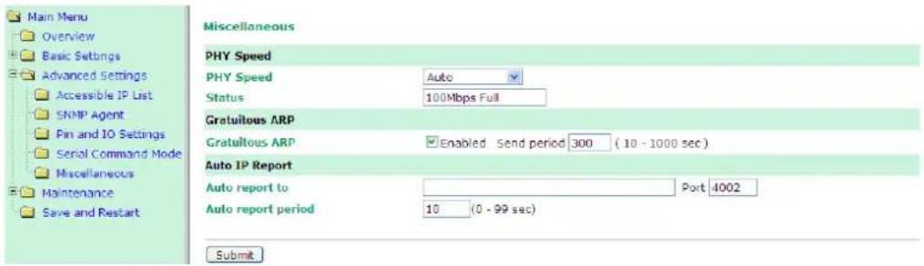
IP Address Report Structure
The first 4 bytes of the module's IP address report are the characters MOXA. The rest of the report is composed of 9 items, with each item preceded by a 2-byte header indicating the item ID and item length.
| Header(Item ID) | Header(Item Length) | Item |
| (none) | (none) | "Moxa" (text string) |
| 1 | (varies) | server name (text string) |
| 2 | 2 | hardware ID (little endian, see table below) |
| 3 | 6 | MAC address (00-90-E8-01-02-03 would be sent in sequence as 0x00, 0x90, 0xE8, 0x01, 0x02, 0x03) |
| 4 | 4 | serial number (little endian DWORD) |
| 5 | 4 | IP address |
| 6 | 4 | Netmask |
| 7 | 4 | default gateway |
| 8 | 4 | firmware version (little endian DWORD, Version 4.3.1= 0x04030100) |
| 9 | 4 | AP ID (little endian DWORD, see table below) |
Example
The following example shows the first 22 bytes of a typical IP address report:
| report header “Moxa” | item ID | item length | server name “TEST” | item ID | item length | hardware ID 0x4119 | item ID | item length | MAC address 00-90-E8-01-02-03 | |||||||||||||
| HEX | 4D | 4F | 58 | 41 | 01 | 04 | 54 | 45 | 53 | 54 | 02 | 02 | 19 | 41 | 03 | 06 | 00 | 90 | E8 | 01 | 02 | 03 |
| ASCII | “M” | “O” | “X” | “A” | “T” | “E” | “S” | “T” | ||||||||||||||
In this appendix, we provide information on sending commands to the module's DIO channels over an Ethernet network. Digital I/O commands and responses are accessed using a specific TCP port (default 5001) on the module. Each command is initiated by the host and is followed by a response from the module. A utility on the CD-ROM can be used to test the DIO access commands.
The following topics are covered in this appendix:
Overview
□ C Code Example
□ Read Single DIO
Command
Response
C Code Example
□ Write Single DIO
Command
Response
C Code Example
□ Read Multiple DIOs
Command
Response
C Code Example
□ Write Multiple DIOs
Command
Response
C Code Example
Overview
Each DIO command and response consists of a 4-byte header and up to 255 bytes of data. The first byte of the header indicates the command. The second byte indicates the version, which is "2" for current firmware versions. The third byte is a code that is used by the module to report errors. The fourth byte is the number of bytes that follows the header, and will depend on the command or response.
In the event of an error, the module will return the entire command as its response, but with the third byte changed according to the following status/error codes:
1: Command error; may be unknown
2: Version error; not supported by this version
3: Length error; the length member does not match the attached data
4: Operation error; invalid status or invalid mode
5: "Packet too short" error
6: DIO number error; might not support requested DIO number
0xFF: other unknown error

ATTENTION
DIO command data is transmitted as values rather than text strings. A value of 1 would be transmitted as 0x01.
C Code Example
//define DIO Header format
typedef struct _DIO_Header_Struct {
char command;
char version; /* This specification is version 2 */
char status;
char length;
} DIOHeaderStruct, *pDIOHeaderStruct;
//define DIO Packet format
//Used for Command and ACK packet
typedef struct _DIO_Packet_Struct {
DIOHeaderStruct header;
Char data[255];
} DIOPacketStruct, *pDIOPacketStruct;
Read Single DIO
Command
| Byte # | Descriptor | Value | Description |
| 1 | Header | 1 | command #, fixed |
| 2 | Header | 2 | version, fixed |
| 3 | Header | (any) | this byte is only used in the module's response |
| 4 | Header | 1 | data length, fixed |
| 5 | Data | 0, 1, 2, 3 | desired DIO channel # |
For example, the 5-byte command sequence 1-2-0-1-0 requests the status of DIO 0.
Response
| Byte # | Descriptor | Value | Description |
| 1 | Header | 1 | command #, fixed |
| 2 | Header | 2 | version, fixed |
| 3 | Header | 0, 1, 2, 3,4, 5, 6,0xFF | command status/error code (0 = okay) |
| 4 | Header | 3 | data length, fixed |
| 5 | Data | 0, 1, 2, 3 | desired DIO channel # |
| 6 | Data | 0, 1 | 0: channel is in input mode1: channel is in output mode |
| 7 | Data | 0, 1 | 0: channel status is low1: channel status is high |
For example, the 7-byte response sequence 1-2-0-3-0-0-0 indicates that DIO 0 is in input mode.
C Code Example
BOOL ReadSingleDIO(int port, int *mode, int *status)
{
    DIOPacketStruct packet;
    packet.header.command = 1; // read single DIO command
    packet.header.version = 2; // DIO protocol version
    packet.header.length = 1; // data length
    packet.data[0] = (char)port; // Number of the DIO
    send(SocketFd, (char *)&packet, sizeof(DIOHeaderStruct)+1, 0);
    // Send TCP Packet
    // Process the returned data here.
    return TRUE;
}
Write Single DIO
Command
| Byte # | Descriptor | Value | Description |
| 1 | Header | 2 | command number, fixed |
| 2 | Header | 2 | version, fixed |
| 3 | Header | (any) | this byte is only used in the module's response |
| 4 | Header | 3 | data length, fixed |
| 5 | Data | 0, 1, 2, 3 | desired DIO channel number |
| 6 | Data | 0, 1 | 0: set to input mode1: set to output mode |
| 7 | Data | 0, 1 | this byte is ignored for input mode0: set to low1: set to high |
For example, the 7-byte command sequence 2-2-0-3-0-0-0 requests that DIO 0 be set to digital input mode.
Response
| Byte # | Descriptor | Value | Description |
| 1 | Header | 2 | command number, fixed |
| 2 | Header | 2 | version, fixed |
| 3 | Header | 0, 1, 2, 3,4, 5, 6,0xFF | command status/error code (0 = okay) |
| 4 | Header | 3 | data length, fixed |
| 5 | Data | 0, 1, 2, 3 | desired DIO channel # |
| 6 | Data | 0, 1 | 0: channel has been changed to input mode1: channel has been changed to output mode |
| 7 | Data | 0, 1 | this byte is ignored for input mode0: channel status has been changed to low1: channel status has been changed to high |
For example, the 7-byte response sequence 2-2-0-3-0-0-0 indicates that DIO 0 has been changed to input mode.
C Code Example
void WriteSingleDIO(int port, int mode, int status)
{
    DIOPacketStruct packet;
    packet.header.command = 2; // write single DIO command
    packet.header.version = 2; // DIO protocol version
    packet.header.length = 3; // data length
    packet.data[0] = (char)port; // number of the DIO
    packet.data[1] = (char)mode; // DIO mode
    packet.data[2] = (char)status; // DIO status;
    send(SocketFd, (char *)&packet, sizeof(DIOHeaderStruct)+3, 0);
    //Send TCP packet
    //Process the returned data here
}
Read Multiple DIOs
Command
| Byte # | Descriptor | Value | Description |
| 1 | Header | 5 | command number, fixed |
| 2 | Header | 2 | version, fixed |
| 3 | Header | (any) | this byte is only used in the module's response |
| 4 | Header | 2 | data length, fixed |
| 5 | Data | 0, 1, 2 | starting DIO channel number |
| 6 | Data | 1, 2, 3 | ending DIO channel number |
This command requests the status of a range of DIO channels, specified in bytes 5 and 6. For example, the 6-byte command sequence 5-2-0-2-0-2 requests the status of DIO channels 0 through 2.
Response
| Byte # | Descriptor | Value | Description |
| 1 | Header | 5 | command number, fixed |
| 2 | Header | 2 | version, fixed |
| 3 | Header | 0, 1, 2, 3,4, 5, 6,0xFF | command status/error code (0 = okay) |
| 4 | Header | 4, 6, 8 | data length, depends on the number of DIO channels requested |
| 5 | Data | 0, 1 | 1st requested DIO channel0: channel is in input mode1: channel is in output mode |
| 6 | Data | 0, 1 | 1st requested DIO channel0: channel status is low1: channel status is high |
| 7 | Data | 0, 1 | 2nd requested DIO channel0: channel is in input mode1: channel is in output mode |
| 8 | Data | 0, 1 | 2nd requested DIO channel0: channel status is low1: channel status is high |
| 9 | Data | 0, 1 | 3rd requested DIO channel, optional0: channel is in input mode1: channel is in output mode |
| 10 | Data | 0, 1 | 3rd requested DIO channel, optional0: channel status is low1: channel status is high |
| 11 | Data | 0, 1 | 4th requested DIO channel, optional0: channel is in input mode1: channel is in output mode |
| 12 | Data | 0, 1 | 4th requested DIO channel, optional0: channel status is low1: channel status is high |
For example, the 10-byte response 5-2-0-6-0-0-1-1-0-1 indicates that DIO 0 is in input mode and "low" status, DIO 1 is in output mode and "high" status, and DIO 2 is in input mode and "high" status.
C Code Example
BOOL ReadMultipleDIO(int start, int end, int *mode, int *status)
{
    DIOPacketStruct packet;
    packet.header.command = 5; // Read Multiple DIO Commands
    packet.header.version = 2; // DIO protocol command version
    packet.header.length = 2; // data length
    packet.data[0] = start; // start of the DIO number
    packet.data[1] = end; // end of the DIO number
    send(SocketFd, (char *)&packet, sizeof(DIOHeaderStruct)+2, 0);
    // Send TCP packet
    // Process the returned data here
    return TRUE;
}
Write Multiple DIOs
Command
| Byte # | Descriptor | Value | Description |
| 1 | Header | 6 | command number, fixed |
| 2 | Header | 2 | version, fixed |
| 3 | Header | (any) | this byte is only used in the module's response |
| 4 | Header | 6, 8, 10 | data length, depends on the number of channels being written (6 bytes for 2 channels, 8 bytes for 3 channels 10 bytes for 4 channels) |
| 5 | Data | 0, 1, 2 | starting DIO channel number |
| 6 | Data | 1, 2, 3 | ending DIO channel number |
| 7 | Data | 0,1 | 1st DIO channel to be written0: set to input mode1: set to output mode |
| 8 | Data | 0, 1 | 1st DIO channel to be written0: set to low1: set to high |
| 9 | Data | 0, 1 | 2nd DIO channel to be written0: set to input mode1: set to output mode |
| 10 | Data | 0, 1 | 2nd DIO channel to be written0: set to low1: set to high |
| 11 | Data | 0, 1 | 3rd DIO channel to be written, optional0: set to input mode1: set to output mode |
| 12 | Data | 0, 1 | 3rd DIO channel to be written, optional0: set to low1: set to high |
| 13 | Data | 0, 1 | 4th DIO channel to be written, optional0: set to input mode1: set to output mode |
| 14 | Data | 0, 1 | 4th DIO channel to be written, optional0: set to low1: set to high |
This command writes the status of a range of DIO channels, specified in bytes 5 and 6. The length of the command depends on the number of channels to be written. For example, the 10-byte command 6-2-0-6-0-1-0-0-1-1 requests DIO 0 be set to digital input mode and "low" status and DIO 1 be set to digital output mode and "high" status. If you wanted to include a change of DIO 2 to digital output mode and "low" status, the 12-bye command sequence would be 6-2-0-8-0-2-0-0-1-1-1-0.
Response
| Byte # | Descriptor | Value | Description |
| 1 | Header | 6 | command number, fixed |
| 2 | Header | 2 | version, fixed |
| 3 | Header | 0, 1, 2, 3,4, 5, 6,0xFF | command status/error code (0 = okay) |
| 4 | Header | 4, 6, 8 | data length, depends on the number of DIO channels requested |
| 5 | Data | 0, 1 | 1st requested DIO channel, 0: channel has been changed to input mode, 1: channel has been changed to output mode |
| 6 | Data | 0, 1 | 1st requested DIO channel, 0: channel status has been changed to low, 1: channel status has been changed to high |
| 7 | Data | 0, 1 | 2nd requested DIO channel, 0: channel has been changed to input mode, 1: channel has been changed to output mode |
| 8 | Data | 0, 1 | 2nd requested DIO channel, 0: channel status has been changed to low, 1: channel status has been changed to high |
| 9 | Data | 0, 1 | 3rd requested DIO channel, optional, 0: channel has been changed to input mode, 1: channel has been changed to output mode |
| 10 | Data | 0, 1 | 3rd requested DIO channel, optional, 0: channel status has been changed to low, 1: channel status has been changed to high |
| 11 | Data | 0, 1 | 4th requested DIO channel, optional, 0: channel has been changed to input mode, 1: channel has been changed to output mode |
| 12 | Data | 0, 1 | 4th requested DIO channel, optional, 0: channel status has been changed to low, 1: channel status has been changed to high |
For example, the 8-byte response 6-2-0-4-0-0-1-1 indicates that DIO 0 has been changed to input mode and "low" status and DIO 1 has been changed to output mode and "high" status.
C Code Example
void WriteMultipleDIO(int start, int end, int* mode, int* status)
{
    DIOPacketStruct packet;
    packet.header.command = 6; // Write Multiple DIO Command Codes
    packet.header.version = 2; // DIO protocol version
    packet.header.length = (end-start+1)*2+2; // data length
    packet.data[0] = start; // start DIO number
    packet.data[1] = end; // end DIO number
    int i, len;
    for (i=0; i<(end-start+1);i++) {
    packet.data[i+2] = mode[i];
    packet.data[i+3] = status[i];
    }
    send(SocketFd, ) (char*)&packet,(end-start+1)*2+2+sizeof(DIOHeaderStruct), 0);
    //Send TCP packet
    //Process the returned data here
}
SNMP Agent with MIB II and RS-232 Like Groups
MiiNePort Series modules have SNMP (Simple Network Management Protocol) agent software built in. The software supports RFC1317 RS-232 like groups and RFC 1213 MIB-II. The following table lists the standard MIB-II groups, as well as the variable implementations for the MiiNePort Series modules.
RFC1 213 MIB-II supported SNMP variables:
| System MIB | Interfaces MIB | IP MIB | ICMP MIB |
| SysDescr | itNumber | ipForwarding | IcmpInMsgs |
| SysObjectID | ifIndex | ipDefaultTTL | IcmpInErrors |
| SysUpTime | ifDescr | ipInreceives | IcmpInDestUnreachs |
| SysContact | ifType | ipInHdrErrors | IcmpInTimeExcds |
| SysName | ifMtu | ipInAddrErrors | IcmpInParmProbs |
| SysLocation | ifSpeed | ipForwDatagrams | IcmpInSrcQuenchs |
| SysServices | ifPhysAddress | ipInUnknownProtos | IcmpInRedirects |
| ifAdminStatus | ipInDiscards | IcmpInEchos | |
| ifOperStatus | ipInDelivers | IcmpInEchoReps | |
| ifLastChange | ipOutRequests | IcmpInTimestamps | |
| ifInOctets | ipOutDiscards | IcmpTimestampReps | |
| ifInUcastPkts | ipOutNoRoutes | IcmpInAddrMasks | |
| ifInNUcastPkts | ipReasmTimeout | IcmpOutMsgs | |
| ifInDiscards | ipReasmReqds | IcmpOutErrors | |
| ifInErrors | ipReasmOKs | IcmpOutDestUnreachs | |
| ifInUnknownProtos | ipReasmFails | IcmpOutTimeExcds | |
| ifOutOctets | ipFragOKs | IcmpOutParmProbs | |
| ifOutUcastPkts | ipFragFails | IcmpOutSrcQuenchs | |
| ifOutNUcastPkts | ipFragCreates | IcmpOutRedirects | |
| ifOutDiscards | ipAdEntAddr | IcmpOutEchos | |
| ifOutErrors | ipAdEntIfIndex | IcmpOutEchoReps | |
| ifOutQLen | ipAdEntNetMask | IcmpOutTimestamps | |
| ifSpecific | ipAdEntBcastAddr | IcmpOutTimestampReps | |
| ipAdEntReasmMaxSize | IcmpOutAddrMasks | ||
| IpNetToMediaIfIndex | IcmpOutAddrMaskReps | ||
| IpNetToMediaPhysAddress | |||
| IpNetToMediaNetAddress | |||
| IpNetToMediaType | |||
| IpRoutingDiscards |
| UDP MIB | TCP MIB | SNMP MIB |
| UdpInDatagrams | tcpRtoAlgorithm | snmpInPkts |
| UdpNoPorts | tcpRtoMin | snmpOutPkts |
| UdpInErrors | tcpRtoMax | snmpInBadVersions |
| UdpOutDatagrams | tcpMaxConn | snmpInBadCommunityNames |
| UdpLocalAddress | tcpActiveOpens | snmpInASNParseErrs |
| UdpLocalPort | tcpPassiveOpens | snmpInTooBigs |
| tcpAttemptFails | snmpInNoSuchNames | |
| Address Translation MIB | tcpEstabResets | snmpInBadValues |
| AtIfIndex | tcpCurrEstab | snmpInReadOnly |
| AtPhysAddress | tcpInSegs | snmpInGenErrs |
| AtNetAddress | tcpOutSegs | snmpInTotalReqVars |
NECI (Network Enabler Configuration Interface) is a set of APIs that run on Windows systems (95 and above) to search, locate, and configure MiiNePort Series modules over the network. The MiiNePort Series library can be found in the folder .\NECI_LIB\ on the Documentation and Software CD included with each module. For more information, refer to NECI.chm in that directory as well as examples located in .\NECI_LIB\VC\ConsoleExample.