
WD-52627 - TV MITSUBISHI - Free user manual and instructions
Find the device manual for free WD-52627 MITSUBISHI in PDF.


| Product Type | Projection Television (DLP) |
| Screen Size | 52 inches (16:9 widescreen) |
| Display Technology | DLP (Digital Light Processing) |
| Maximum Resolution | 1920 x 1080 (1080p) |
| Inputs | ANT-1 MAIN, ANT-2 AUX, Component (3 sets), HDMI (2), S-Video, Composite, DVI Analog Audio, IEEE 1394 (3 ports), IR Emitter, CableCARD slot |
| Outputs | Digital Audio (coaxial), Analog Audio (RCA), Record Output (composite) |
| NetCommand | IR learning and IEEE 1394 control for home theater devices |
| TV Guide On Screen | 8-day interactive program guide (subscription-free) |
| Media Card Support | SmartMedia, SD/MMC, CompactFlash, Memory Stick (JPEG, MP3, WMA) |
| Lamp Type | Replaceable high-brightness lamp (part #915P026010) |
| Remote Control | Yes, with batteries (AAA) |
| Accessories Included | Remote, 2 AAA batteries, IR emitter cable, owner's guide, quick reference card |
| Stand Requirement | Mitsubishi model MB-52527 only |
| Cleaning | Unplug before cleaning; use a damp cloth only |
| Safety Features | Polarized plug, ventilation slots, auto-shutoff, V-Chip parental controls |
| Warranty | 1 year parts and labor (screen 30 days, lamp 1 year) |
Frequently Asked Questions - WD-52627 MITSUBISHI
User questions about WD-52627 MITSUBISHI
0 question about this device. Answer the ones you know or ask your own.
Ask a new question about this device
Download the instructions for your TV in PDF format for free! Find your manual WD-52627 - MITSUBISHI and take your electronic device back in hand. On this page are published all the documents necessary for the use of your device. WD-52627 by MITSUBISHI.
USER MANUAL WD-52627 MITSUBISHI
Projection Television Models
WD-52627, WD-62627
Owner's Guide




TV Information:
Use this space to record the model and serial numbers of your television. This information is on the back of your TV
Model number
Serial number
visit our website at at
www.mitsubishi-tv.com
CAUTION
RISK OF ELECTRIC SHOCK DO NOT OPEN

CAUTION: TO REDUCE THE RISK OF ELECTRIC SHOCK, DO NOT REMOVE COVER (OR BACK). NO USER SERVICEABLE PARTS INSIDE. REFER SERVICING TO QUALIFIED SERVICE PERSONNEL.
The lightning flash with arrowhead symbol within an equilateral triangle is intended to alert the user of the presence of uninsulated “dangerous voltage” within the product’s enclosure that may be sufficient magnitude to constitute a risk of electric shock.

The exclamation point within an equilateral triangle is intended to alert the user to the presence of important operating and maintenance (servicing) instructions in the literature accompanying the appliance.
This TV is heavy! Exercise extreme care when lifting or moving. Lifting or moving the TV requires a minimum of two adults. To prevent damage to your TV, your TV should not be jarred or moved while it is turned on. Power off your TV before moving it.
Portions of the advanced circuitry of this TV must continue to operate even when the TV is turned off. Some of these circuits therefore need to be cooled at all times. A low power standby fan may be heard in a quiet environment. This is normal operation.
Custom cabinet installation must allow for proper air circulation around the television.
TV Guide On Screen® Access Requirements
TV Guide On Screen listings are not provided by Mitsubishi Digital Electronics America, Inc. Operation of TV Guide On Screen requires over-the-air or cable access to stations carrying TV Guide On Screen program listings. If listings are not available in your area or become discontinued by the local provider, TV Guide On Screen will not operate. TV Guide On Screen does not provide program listings for satellite TV systems.
Stand Requirement
CAUTION: Mitsubishi TV model WD-52627 is for use only with Mitsubishi stand model MB-52527. Mitsubishi TV model WD-62627 is for use only with Mitsubishi stand model MB-62527. Use with other stands is capable of resulting in instability causing possible injury.
Lamp Replacement
The image on this TV is produced by a high-brightness lamp that will operate for many hours. Eventually, however, this lamp will need to be replaced. It is designed to be easily replaced by the TV owner. Front panel indicators and/or on-screen messages will assist you in determining when the lamp needs to be replaced. Please see Appendix H for details on lamp replacement.
To order a new lamp:
| While Under Warranty After Warranty | |
| Call (800) 332-2119. Please have model number, serial number, and TV purchase date available. | Call (800) 553-7278. Order lamp part number 915P026010. |
WARNING: TO REDUCE THE RISK OF FIRE OR ELECTRIC SHOCK, DO NOT EXPOSE THIS APPLIANCE TO RAIN OR MOISTURE.
CAUTION: TO PREVENT ELECTRIC SHOCK, MATCH WIDE BLADE OF PLUG TO WIDE SLOT, FULLY INSERT.
NOTE TO CATV SYSTEM INSTALLER: THIS REMINDER IS PROVIDED TO CALL THE CATV SYSTEM INSTALLER'S ATTENTION TO ARTICLE 820-40 OF THE NEC THAT PROVIDES GUIDELINES FOR THE PROPER GROUNDING AND, IN PARTICULAR, SPECIFIES THAT THE CABLE GROUND SHALL BE CONNECTED TO THE GROUNDING SYSTEM OF THE BUILDING, AS CLOSE TO THE POINT OF CABLE ENTRY AS PRACTICAL.
FCC Declaration of Conformity
Product: Projection Television Receiver
Models: WD-52627, WD-62627
Responsible Party: Mitsubishi Digital Electronics America, Inc.
9351 Jeronimo Road
Irvine, CA 92618-1904
Telephone: 949-465-6000
This device complies with Part 15 of the FCC Rules. Operation is subject to the following two conditions:
(1) This device may not cause harmful interference, and
(2) this device must accept any interference received, including interference that may cause undesired operation.
Note: This equipment has been tested and found to comply with the limits for a Class B digital device, pursuant to part 15 of the FCC Rules. These limits are designed to provide reasonable protection against harmful interference in a residential installation. This equipment generates, uses and can radiate radio frequency energy and, if not installed and used in accordance with the instructions, may cause harmful interference to radio communications. However, there is no guarantee that interference will not occur in a particular installation. If this equipment does cause harmful interference to radio or television reception, which can be determined by turning the equipment off and on, the user is encouraged to try to correct the interference by one or more of the following measures:
- Reorient or relocate the receiving antenna.
- Increase the separation between the equipment and the receiver.
- Connect the equipment into an outlet on a circuit different from that to which the receiver is connected.
- Consult the dealer or an experienced radio/TV technician for help.

CAUTION: To ensure continued FCC compliance, the user must use a shielded video interface or HDMI cable with bonded ferrite cores at both ends when using the PC input.
Changes or modifications not expressly approved by Mitsubishi could cause harmful interference and would void the user's authority to operate this equipment.
IMPORTANT SAFEGUARDS
Please read the following safeguards for your TV and retain for future reference. Always follow all warnings and instructions marked on the television.
1. Read, Retain and Follow All Instructions
Read all safety and operating instructions before operating the TV. Retain the safety and operating instructions for future reference. Follow all operating and use instructions.
2. Heed Warnings
Adhere to all warnings on the appliance and in the operating instructions.
3. Cleaning
Unplug the TV from the wall outlet before cleaning. Do not use liquid, abrasive or aerosol cleaners. Cleaners can permanently damage the cabinet and screen. Use a lightly dampened cloth for cleaning.
4. Attachments and Equipment
Never add any attachments and/or equipment without approval of the manufacturer as such additions may result in the risk of fire, electric shock or other personal injury.
5. Water and Moisture
Do not use the TV where contact with or immersion in water is possible. Do not use near bath tubs, wash bowls, kitchen sinks, laundry tubs, swimming pools, etc.
6. Accessories
natural_image
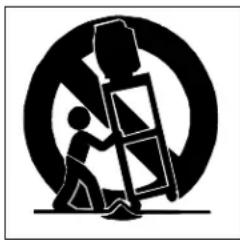
Silhouette of a person climbing a ladder inside a circular frame (no text or symbols)Do not place the TV on an unstable cart, stand, tripod, or table. The TV may fall, causing serious injury to a child or adult and serious damage to the TV. Use only with a cart, stand, tripod, bracket or table recommended by the manufacturer, or sold with the TV. Any mounting of the TV should follow the manufacturer's instructions, and should use mounting accessories recommended by the manufacturer.
An appliance and cart combination should be moved with care. Quick stops, excessive force, and uneven surfaces may cause the appliance and cart combination to overturn.
7. Ventilation
Slots and openings in the cabinet are provided for ventilation and to ensure reliable operation of the TV and to protect it from overheating. Do not block these openings or allow them to be obstructed by placing the TV on a bed, sofa, rug, or other similar surface. Nor should it be placed over a radiator or heat register. If the TV is to be placed in a rack or bookcase, ensure that there is adequate ventilation and that the manufacturer's instructions have been adhered to.
8. Power Source
This TV should be operated only from the type of power source indicated on the marking label. If you are not sure of the type of power supplied to your home, consult your appliance dealer or local power company.
9. Grounding or Polarization
This TV is equipped with a polarized alternating current line plug having one blade wider than the other. This plug will fit into the power outlet only one way. If you are unable to insert the plug fully into the outlet, try reversing the plug. If the plug should still fail to fit, contact your electrician to replace your obsolete outlet. Do not defeat the safety purpose of the polarized plug.
10. Power-Cord Protection
Power-supply cords should be routed so that they are not likely to be walked on or pinched by items placed upon or against them, paying particular attention to cords at plugs, convenience receptacles, and the point where they exit from the TV.
11. Lightning
For added protection for this TV during a lightning storm, or when it is left unattended and unused for long period of time, unplug it from the wall outlet and disconnect the antenna or cable system. This will prevent damage to the TV due to lightning and power-line surges.
IMPORTANT SAFEGUARDS, continued
12. Power Lines
An outside antenna system should not be located in the vicinity of overhead power lines or other electric light or power circuits, or where it can fall into such power lines or circuits. When installing an outside antenna system, extreme care should be taken to keep from touching such power lines or circuits as contact with them might be fatal.
13. Overloading
Do not overload wall outlets and extension cords as this can result in a risk of fire or electric shock.
14. Object and Liquid Entry
Never push objects of any kind into this TV through openings as they may touch dangerous voltage points or short-out parts that could result in fire or electric shock. Never spill liquid of any kind on or into the TV.
15. Outdoor Antenna Grounding
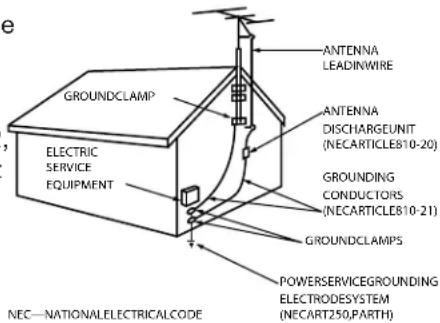
If an outside antenna or cable system is connected to the TV, be sure the antenna or cable system is grounded so as to provide some protection against voltage surges and built-up static charges.
Article 810 of the National Electric Code, ANSI/NFPA No. 70-2002, provides information with respect to proper grounding of the mast and supporting structure, grounding of the lead in wire to an antenna discharge unit, size of grounding conductors, location of antenna discharge unit, connection to grounding electrodes, and requirements for the grounding electrode.
EXAMPLEOFANTENNAGROUNDING
16. Servicing
Do not attempt to service this TV yourself as opening or removing covers may expose you to dangerous voltage or other hazards. Refer all servicing to qualified service personnel.
17. Damage Requiring Service
Unplug the TV from the wall outlet and refer servicing to qualified service personnel under the following conditions:
(a) When the power-supply cord or plug is damaged.
(b) If liquid has been spilled, or objects have fallen into the TV.
(c) If the TV has been exposed to rain or water.
(d) If the TV does not operate normally by following the operating instructions, adjust only those controls that are covered by the operating instructions as an improper adjustment of other controls may result in damage and will often require extensive work by a qualified technician to restore the TV to its normal operation.
(e) If the TV has been dropped or the cabinet has been damaged.
(f) When the TV exhibits a distinct change in performance - this indicates a need for service.
18. Replacement Parts
When replacement parts are required, be sure the service technician has used replacement parts specified by the manufacturer or have the same characteristics as the original part. Unauthorized substitutions may result in fire, electric shock or other hazards.
19. Safety Check
Upon completion of any service or repair to the TV, ask the service technician to perform safety checks to determine that the TV is in safe operating condition.
20. Heat
The product should be situated away from heat sources such as radiators, heat registers, stoves or other products (including amplifiers) that produce heat.
Contents
Chapter 1: Television Overview
TV Accessories 10
Special Features.... 11
Front Control Panel 12
Remote Control Overview 14
Battery Installation 15
Care 15
Sleep Timer.... 15
TV Back Panel.... 16
Media Card Slots 18
Front-Panel Input 3. 18
Using the System Reset Button.... 19
Using the Reset Menu to Reset the TV 19
Chapter 2: Connecting
External Devices and NetCommand® Setup 22
CableCARD™ Technology 23
Wall Outlet Cable 24
Standard Cable Box 24
Antenna with a Single Lead 25
Antennas with Separate UHF and VHF Leads 25
VCR to an Antenna or Wall Outlet Cable (Audio & Video).... 26
VCR to a Cable Box (Audio & Video) 27
A/V Receiver (Stereo System) 28
Satellite Receiver or Other Device with S-Video 28
DVD Player with Component Video 29
DVI Device 29
HDTV Cable Box or Satellite Receiver with Component Video 30
HDMI Device 30
Computer with an HDMI Monitor Output 31
Computer with a DVI Monitor Output 31
IR Emitter NetCommand® 32
Compatible IEEE 1394 Devices 33
Helpful Hints 35
Chapter 3: NetCommand® Setup and Editing
NetCommand® Introduction 38
Using the Remote Control with NetCommand® 39
NetCommand® Setup On-Screen Buttons 40
3D Graphical ▶ViewPoint™ Menu System 41
NetCommand® Initial Setup 42
Edit NetCommand®: Add an A/V Receiver 45
Edit NetCommand®: Add Devices 48
Edit NetCommand®: Change or Delete Devices 52
Chapter 4: IEEE 1394 Devices and NetCommand®-Controlled Recordings
IEEE 1394 Devices and NetCommand® Control 54
Adding IEEE 1394 Devices Automatically 55
Device Selection Menu 57
Using the Device Menu Button to Display Menus 58
Using the GUIDE Button to Display ChannelView™ and Menus 59
NetCommand®-Controlled Recordings 60
Chapter 5: TV Menu Screen Operations
Main Menu 64
Setup Menu 65
NetCommand® Menu 67
Record Menu 68
Channel Menu 70
Captions Menu 72
V-Chip Lock Menu 74
Audio/Video Menu 77
A/V Setting Descriptions: Audio 78
A/V Setting Descriptions: Video 79
Chapter 6: Additional Features
Operation of PIP 82
TV Display Formats 83
PC Viewing. 85
PC Display Formats 86
MediaCommand™ and Media Card Playback 87
Chapter 7: Troubleshooting 89
Appendices
Appendix A: Bypassing the V-Chip Lock 97
Appendix B: Specifications 99
Appendix C: Remote Control Programming Codes 101
Appendix D: Device Control with NetCommand® 104
Appendix E: NetCommand® Specialized Device Keys 106
Appendix F: On-Screen Information Displays 107
Appendix G: Cleaning and Service 108
Appendix H: Lamp Cartridge Replacement.... 109
Trademark and License Information 111
Index 113
Mitsubishi DLP™ Projection Television Limited Warranty 115
Our Thanks...
Thank you for choosing Mitsubishi as your premier Home Entertainment provider
This Owner's Guide describes the features and functions of your Mitsubishi widescreen, high definition TV. We urge you to examine this Owner's Guide to become familiar with the innovative features and operations this unique television offers.
The very core of our corporate philosophy is to provide our customers with the very best. Our development team at Mitsubishi has worked to provide you with a television that defines “state-of-the-art,” with the capability to meet your needs now and in the future.
Whether this is your first Mitsubishi electronic product, or an addition to your Mitsubishi collection, we believe you and your family will continue to enjoy your Mitsubishi home theater for many years.
Thank you,
Mitsubishi Digital Electronics America, Inc.
Chapter ...

Television Overview
TV Accessories 10
Special Features.... 11
Front Control Panel.... 12
Remote Control
Overview 14
Battery Installation 15
Care 15
Sleep Timer 15
TV Back Panel 16
Media Card Slots 18
Front-Panel Input 3....18
Using the System Reset Button 19
Using the Reset Menu to Reset the TV 19
TV Accessories
Please take a moment to review the following list of items to ensure that you have received everything including:
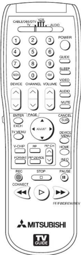
- Remote Control
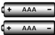
2. Two AAA Batteries
natural_image
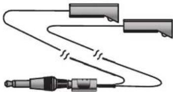
Pure electrical circuit lines without any symbols3 One Double IR Emitter Cable (allows NetCommand to control other devices)
-
Product Registration Card (not pictured)
-
Owner's Guide (not pictured)
-
Quick Reference Card (not pictured)
-
TV Guide On Screen® Interactive Program Guide User's Manual (not pictured)
Special Features
Your new High Definition widescreen television has many special features that make it the perfect center of your home entertainment system, including:
High Definition DLP™ Display System
Your widescreen Mitsubishi HDTV uses Texas Instruments most advanced Digital Light Processing™ technology for rear projection televisions. This TV is truly a high-performance multimedia monitor uniquely capable of both stunning high-definition video images and clear, detailed, high-resolution PC images. Your TV is able to accept video signals from an antenna or direct cable in standard video scanning rates of 480i, 480p, 720p, 1080i and 1080p. It is also able to accept, through the HDMI 2 connection, signals with PC resolutions from VGA (640 x 480) through XGA (1024 x 768). When used with a compatible graphics card and controlling software, this TV is also able to accept the custom PC resolution of 720p (1280 x 720). When connecting a PC to HDMI you will need a PC video card with DVI or HDMI output. Also, so the TV can apply the correct PC signal processing, you will need to set up the TV to receive the PC signals through the HDMI 2 input by using the NetCommand setup system. All of the compatible video and PC signals will be converted to 1080p for final display; some signals will, however, add black side bars, top and bottom bars, or both to fill the screen, and some signals will display standard video overscan.
TV Guide On Screen® Interactive Program Guide System
An eight-day on-screen program guide that can be used with cable, over-the-air and CableCARD™ reception. The subscription-free guide system lists regular, digital and high-definition programming. This system allows multiple sorting options and easy program recording. Program listings are downloaded while your TV is turned off, so that you have current program information available every day. Note that when the system is first set up, it may take up to 24 hours to begin to receive TV program listings. It may take one week to receive all eight days of TV program listings.
Digital Cable Ready (CableCARD™)
Your widescreen Mitsubishi HDTV is “Plug-and-Play” ready. It can descramble a cable provider’s one-way digital signals with the use of a CableCARD security module. The CableCARD is used in place of a traditional cable box to access digital cable programming (including high definition). Contact your local cable provider for availability information and service details.
NetCommand® Home Network Control System
Your widescreen Mitsubishi HDTV offers a new level of networking to combine selected older products with new and future digital products. NetCommand supports IEEE 1394 connections, Audio Video Control system (AV/C), 5C copy protection and IR control of selected older products such as VCRs, DVD players, cable boxes or satellite receivers. NetCommand includes the ability to learn remote control signals directly from many devices, allowing you to customize the NetCommand system in a way that works best for your viewing
16:9 Widescreen Picture Format
Enjoy a full theatrical experience in the comfort of your home. View pictures as film directors intended them. Digital TV broadcasts, DVDs and newer video game consoles support this widescreen format.
Media Cards
You can display a slide show of your favorite JPEG pictures or listen to MP3 or WMA audio selections that have been recorded on compatible media cards
Front Control Panel
The shaded buttons on the front control panel are duplicated on the remote control. The top row of labels shows the control functions when there are no TV menus displayed on the screen. The bottom row of labels shows the control functions when the TV menus are displayed on the screen or when a special function has been activated. See "Remote Control Overview" for further details on the functions of these buttons.

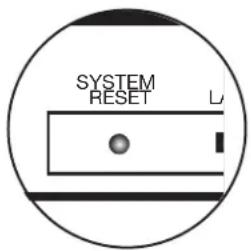
System Reset
If the TV does not respond to either the remote control or the front panel controls and/or does not power Off, press the SYSTEM RESET button with a pointed item like the end point of a paperclip. The TV will turn Off and the TIMER light will flash quickly for about one minute. When the TIMER light stops flashing, you may again turn on the TV. The changes you made the last time the TV was on before you used the SYSTEM RESET button may be lost; any changes that were previously saved are not lost, however.
A/V Reset
There may be times when you wish to reset the A/V (Audio and Video) settings back to the factory defaults. To return all of the settings at once, press GUIDE and FORMAT on the front panel at the same time. To reset the defaults for individual devices, use the A/V Memory Reset selection on the Audio/Video menu.
Front-Panel Indicator Lights

| Power/Timer Indicator | ||
| Indicator Color TV Condition Additional Information | ||
| None (indicator off) | TV is powered OFF. | Normal operation. |
| Green, steady | TV is powered ON. | Normal operation. |
| Green, rapid blinking | 1. TV just plugged into AC outlet. Wait until blinking stops before turning on (approximately 1 minute). Normal operation. | |
| 2. AC just restored after power failure. | Wait until blinking stops before turning on (approximately 1 minute). Normal operation. | |
| 3. TV Rebooting after System Reset used. | Wait until blinking stops before turning on (approximately 1-2 minutes). Normal operation. | |
| 4. TV Rebooting after power fluctuation or receiving abnormal digital signals from digital channel, CableCARDTM, or digital device. | Wait until blinking stops before turning on (approximately 1 minute). Normal operation. | |
| 5. You have begun the procedure to update software from an authorized flash memory device. | For detailed information, see the instructions that accompany the authorized software update. Important: Do not use non-authorized software at any time. | |
| Green, slow blinking | TV powered off and automatic-on timer is set. | Normal operation. TV can be turned on at any time. |
Front Control Panel, continued
| Status Indicator | ||
| Indicator Color TV Condition Additional Information | ||
| None (indicator off) | Normal TV on or standby condition. Normal operation. | |
| Yellow, steady Room | temperature is too high. TV will not operate when the ambient room temperature is too high. Turn off the TV and wait until the room temperature drops. | |
| Red, either steady or blinking | TV may require service. Turn off the TV and unplug the set from the AC power source. Wait one minute and then plug the set back in.If the LED is still on, contact your dealer or a Mitsubishi Authorized Service Center. See www.mitsubishi-tv.com or call 1-800-332-2119 to receive Authorized Service Center information. | |
| Lamp Indicator | ||
| Indicator Color TV Condition Additional Information | ||
| None (indicator off) | Normal TV on or standby condition. Normal operation. | |
| Green, rapid blinking | TV just powered off and lamp is cooling. | Begins to blink 30 seconds after turning off TV. TV can be turned on before it begins to blink or after the blinking stops, but not while the indicator is blinking. Normal operation. |
| Yellow, steady Lamp | nearing end of useful life. This is a recommend | endation to have a new lamp ready before the current lamp stops illuminating. See Appendix H for ordering information. |
| Yellow, blinking 1. Lamp | access door is open or not secure. | TV will not operate until lamp access door is secure. See Appendix H for installation information. |
| 2. No lamp installed. TV will not operate | without a lamp. See Appendix H for installation information. | |
| Red, steady Lamp no | onger illuminates and has reached the end of the lamp life. | Replace the lamp. The TV will not operate when the lamp no longer illuminates. See Appendix H for installation information. |
Remote Control
Overview
Figure 1, following page
- Slide Switch: Selects A/V product to be controlled by the remote control. Select TV for NetCommand® device control.
- Numbers: Individually select channels or enter information into menus.
- POWER: Turns power on and off for TV and other A/V products.
- GUIDE: Displays or removes TV Guide On Screen or ChannelView for ANT-1 and 2. Displays Track List for A/V Disc. Displays program guide for satellite receiver, or DVD Disc menu. Displays thumbnails or play lists for media card files.
- SQV (SuperQuickView™): Scans through memorized lists of favorite channels.
- QV (QuickView™): Switches between the current channel and last channel viewed.
- SLEEP: Sets the TV to turn off within 2 hours. See next page for setup instructions.
- VIDEO: Selects and adjusts individual video settings.
- DEVICE: Displays the Device Selection menu to select the device to view (ANT-1 and ANT-2, or devices connected to the TV's inputs, including IEEE 1394 devices).
- CH(ANNEL)/PAGE: Scans up or down through memorized channels. When used with TV Guide On Screen® and ChannelView, pages up and down through screens.
- VOLUME: Changes sound level.
- AUDIO: Selects and adjusts individual audio settings.
- MUTE: Turns sound on or off.
- Light: Located on the left side of the remote control, this feature illuminates buttons or labels.
- ENTER/EXCH: Selects a channel number or menu item. Exchange PIP and main TV picture. If PIP is displayed, it must be cancelled before using the on-screen menus for devices.
- ADJUST: Press ▲▼◀to navigate TV Guide On Screen, menus, change settings, and move the PIP on-screen location. Operates many NetCommand functions.
-
SUB/CANCEL: Clears SQV and some menu entries and cancels recordings. For digital channels, adds separator between major and sub channel numbers.
-
TV MENU: Displays ▶ViewPoint een menu system.
-
DEVICE MENU: Displays or removes the options menu for TV Guide On Screen. Displays the menu for devices connected to the TV, including CableCARD™. For VCR or DVDs, the first press displays the transport menu, the second press displays the VCR or DVD menu.
-
V-CHIP: Turns On or Off the V-Chip Lock.
-
PIP: Turns on PIP and cycles through PIP display choices.
-
PIP CH: Scrolls up or down through memorized channels for PIP
-
HOME: Exits TV on-screen menus and the TV Guide On Screen system and returns to TV viewing.
-
FORMAT: Changes the shape and size of the main TV picture.
-
PIP DEVICE: Displays PIP Selection menu to select the PIP image source device
-
INFO: First press displays an on-screen summary of the current device used and any broadcast information available (including current V-Chip information). See Appendix D for details. While in the TV Guide On Screen system, press the info button to cycle through the available info box sizes.
-
REC (Record)/CONNECT: Displays the Record menu for setting up recordings. Records with a VCR, sets up recordings for DVCR, IEEE 1394 devices, or while in ChannelView. When Listings screen for TV Guide On Screen is displayed, will start a recording.
CONNECT: Initiates IEEE 1394 peer-to-peer connections.
-
STOP: Stops a VCR, DVD, A/V Disc or media card file.
-
PAUSE: Pauses a live TV picture when no PIP image is displayed. When PIP image is visible, pauses that image. Pauses a VCR, DVD or A/V Disc, media card file.
-
REW/REV: Rewinds a VCR. Reverses scan with a DVD, A/V Disc or media card file.
-
PLAY: Plays a VCR, DVD, A/V Disc or media card file.
-
FF/FWD: Fast forward a VCR or media card file, or fast play a DVD.
Remote Control, continued
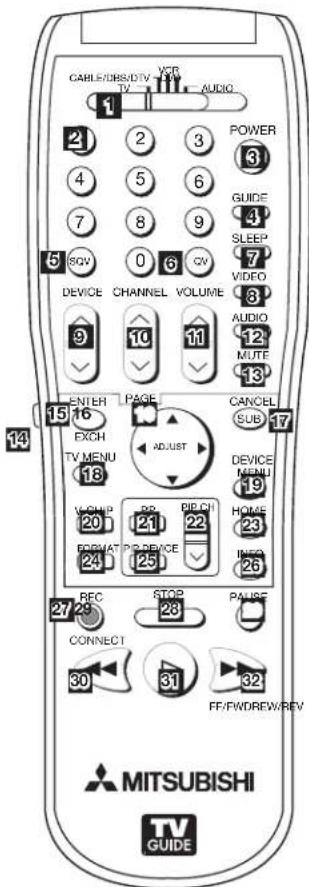
Figure 1. Remote Control Overview
Battery Installation
Figure 2 Installing the Batteries:
- Remove the remote control's back cover by gently pressing the ribbed tab in the direction of the arrow and sliding off the cover.
- Load the batteries, making sure the polarities (+) and (-) are correct. For best results, insert the negative (-) side first.
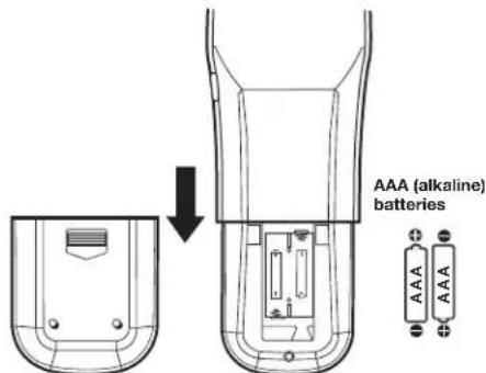
Figure 2. Operation: Installing the Batteries
Chapter 1. Television Overview
Care
For Best Results from the Remote Control:
- Be within 20 feet of the equipment.
- Do not press two or more buttons at the same time unless instructed.
• Do not allow unit to get wet or become heated. - Avoid dropping on hard surfaces.
- Do not use harsh chemicals to clean. Use only a soft, lightly moistened cloth.
• Do not mix new and old batteries. - Do not heat, take apart or throw batteries into fire.
• Use only AAA alkaline batteries.
Hint: If the remote is in the TV layer and does not function, press POWER and 935 to reset the remote.
Sleep Timer
Setting the Sleep Timer:
- Press SLEEP on the remote control.
- Each additional press of SLEEP increases the time displayed by 30 minutes, until the maximum value of 120 minutes is reached.
- After 5 seconds of inactivity, the message will disappear.
- Press SLEEP to view the remaining time before the timer turns the TV off.
Cancelling the Sleep Timer:
- Press SLEEP to display the on-screen message.
- Press SLEEP repeatedly until OFF is displayed.
Note: After 5 seconds of inactivity, the message box disappears.
TV Back Panel
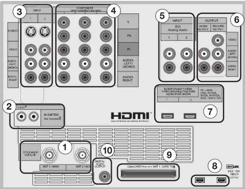
1. Antenna (ANT-1 MAIN, ANT-2 AUX)
ANT-1 MAIN and ANT-2 AUX can each receive both digital and analog over-the-air channels from a VHF/UHF antenna or non-scrambled digital/analog cable source.
Your primary viewing signal source should be connected to ANT-1 MAIN. ANT-1 MAIN must be used to view premium subscription cable TV service authorized by the CableCARD™ access card. The CableCARD access card is provided by your local cable company. ANT-2 AUX can receive over-the-air or non-scrambled cable signals.
2. IR EMITTER NetCommand®
IR Emitters connected to these jacks are used by the NetCommand system of the TV to control external analog devices such as cable boxes, VCRs, DVDs, satellite receivers and audio receivers. This system is also coordinated with the TV Guide On Screen® system for the control of cable boxes and to activate the record feature of your VCR. Either connection can be used for NetCommand functions.
3. INPUT 1 and 2
(Audio/Video 1 and 2)
Inputs 1 and 2 can be used for the connection of a VCR, Super VHS (S-VHS) VCR, DVD player, standard satellite receiver or other A/V device to the TV. Please note that if S-VIDEO and VIDEO are available for the input, you must choose to connect only one. They cannot both be connected at the same time.
4. COMPONENT 1, 2, and 3 Inputs YPbPr (480i/480p/720p/1080i)
These inputs can be used for the connection of devices with component video outputs, such as a DVD player, external HDTV receiver, or compatible video game system. Please see Appendix B for signal compatibility.
5. DVI Analog Audio
Unlike HDMI, DVI does not carry audio information on the same cable. Use these analog stereo audio inputs when using the HDMI input with a device that outputs DVI instead of HDMI, such as DVI output from a personal computer.
6. AUDIO OUTPUT, RECORD OUTPUT
AUDIO OUTPUT sends analog audio of the program currently shown on the screen to an A/V surround sound receiver or stereo system. Digital audio from digital channels, FireWire® (DTV Link/IEEE 1394) devices and HDMI devices is converted to analog audio by the TV. If you do not have a digital A/V receiver, this should be the only audio connection between the TV and your analog A/V receiver or stereo system.
RECORD OUTPUT sends analog audio and video to a VCR for recording purposes. These signals may not be the same as those of the program that is currently being shown on screen. Signals from digital channels and FireWire (IEEE 1394) devices are converted to analog signals. There is no video signal when copy restrictions
TV Back Panel, continued
are in effect. Audio alone is output when Component 1, 2, or 3, or the HDMI input is selected for recording.
7. HDMI ^TM 1 and 2
The HDMI (High Definition Multimedia Interface) supports uncompressed standard and high-definition digital video formats and PCM digital audio format.
Use these inputs to connect to EIA/CEA-861 compliant devices such as a high-definition receiver or DVD player. These inputs support 480i, 480p, 720p and 1080i video formats.
These inputs can also be used as a DVI connection with separate analog audio inputs. An optional HDMI-to-DVI adaptor or cable is necessary to make this connection and may be available from your local electronics retailer. When using the optional HDMI-to-DVI adapter, the DVI analog audio inputs on your TV allow you to receive left and right audio from your DVI device.
This input is HDCP (High-Bandwidth Digital Copy Protection) compliant.
HDMI 2
HDMI 2 also allows the TV to display DVI or HDMI output from a PC. To view PC video on the TV, you must activate the PC option in NetCommand. You can do this during initial NetCommand setup (in the Device Setup screen), or at any time afterwards by using the NetCommand Add function.
If you want audio from a PC when using PC DVI output, you must connect the PC audio output to the TV INPUT/DVI Analog Audio 2, located above the HDMI 2 input.
8. DTV Link™/IEEE 1394
These jacks allow the TV to connect to external IEEE 1394 digital products by means of a single cable. Two jacks are provided for this purpose, which allow for a high degree of flexibility for connecting your NetCommand controlled system. Detailed information regarding IEEE 1394 connection requirements are in Chapter 4.
9. CableCARD™ Slot
The CableCARD access card from your cable TV service provider is inserted into this slot. The top of the card should face in the direction indicated by CARD TOP ▲
CableCARD is a nationwide standard system that allows your local cable TV provider to supply you with an
access card customized to your account. This card allows the TV to receive, decode and unscramble the premium digital channels included in your cable TV subscription without the use of a cable box. See page 23 for additional CableCARD information and activation instructions.
If your cable company is not currently offering CableCARD access cards, you will need to use a cable box provided and authorized by your local cable company to view scrambled channels.
10. Digital Audio Output
This output sends Dolby® Digital or PCM digital audio to your digital A/V surround sound receiver. Analog audio from analog channels and devices is converted by the TV to PCM digital audio. In most cases, this should be the only audio connection between the TV and your A/V receiver. If you have MP3 audio sources, however, you need to connect the TV's analog AUDIO OUTPUT (left and right) to your A/V receiver.
Media Card Slots and Front-Panel Inputs
Media Card Slots
To access the media card slots, press on the center panel labelled PUSH. There are four card slots in the front of the TV that allow the display of JPEG pictures from many digital cameras, MP3 or WMA audio files recorded from computers or other digital recording devices.
The card slots are designed for the specific types of cards listed below. Other cards or objects should not be inserted into the slots as this may damage the TV. See media card (slide show, play list) Setup for details about JPEG, MP3 and WMA file types that are compatible with the TV.
Card Compatibility
Slot Card Types
| CARD 1 SmartMedia ^TM | |
| CARD 2 | MultiMediaCard ^TM Secure Digital (SD) |
| CARD 3 | CompactFlash®,Types I and IIMicrodrive® |
| CARD 4 | Memory Stick PRO ^TM Memory Stick ^TM |
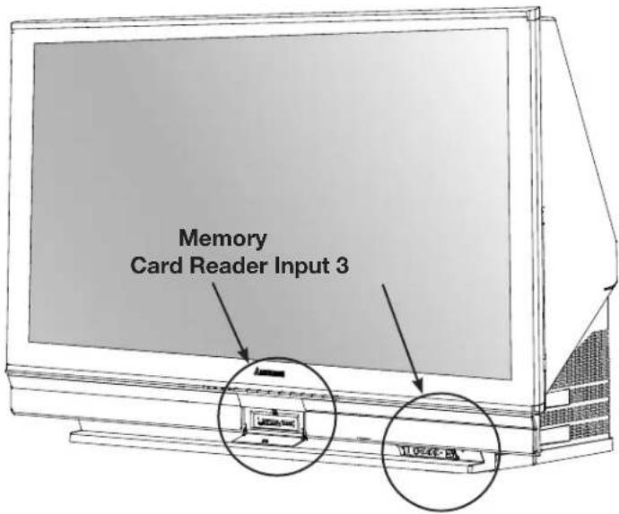
Front-Panel Input 3
These jacks allow for convenient connection of audio/video devices to the front of the TV. Use the Input 3 jacks to connect a camcorder or other audio/video device. Please note that if you connect to the S-VIDEO terminal, the VIDEO terminal is deactivated. The VIDEO terminal is active only when there is no S-Video connection.
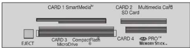
Card slots

Input 3 on front panel
IMPORTANT
Portions of the advanced circuitry of this TV must continue to operate even when the TV is turned off. Some of these circuits therefore need to be cooled at all times. A low-power standby fan may be heard in a quiet environment. This is normal operation.
Additional Information
Using the System Reset Button
If the TV doesn't respond to either the remote control or the front panel controls or will not power off, press the SYSTEM RESET button on the front panel with a pointed item such as the point of a ball point pen or end tip of a paperclip.
The TV will turn off and the green LED will flash quickly for about one minute. When the green LED stops flashing, you may turn on the TV again. The changes you made while the TV was most recently on, before you used the SYSTEM RESET button may be lost; the changes you made previously, however, are not lost. Only those changes since the last power On may be lost when the system reset button is pressed. All other settings are retained.
Using the Reset Menu to Reset the TV
Read on-screen warnings before proceeding, as some user data or settings may be erased.
- Select any device from the Device Selection menu. Press TV MENU followed by 1,2,3 to see the RESET SERVICE MENU to reset the TV.
- Select Reset System Defaults (CAUTION: All settings, except V-Chip, will be reset to the original factory defaults).
Demo Mode
This TV has a demo mode for use in retail stores. To turn the demo mode On/Off, press the following buttons in sequence:
MENU, 0, QV, 0
IMPORTANT
Do not attempt to update the software of this TV with software or cards that are not provided by or authorized by Mitsubishi Digital Electronics America, Inc. Non-authorized software may damage the TV and will not be covered by the warranty.
Chapter ...

Connecting
External Devices and NetCommand® Setup 22
CableCARD™ Technology 23
Wall Outlet Cable 24
Standard Cable Box 24
Antenna with a Single Lead 25
Antennas with Separate UHF and VHF Leads. 25
VCR to an Antenna or Wall Outlet Cable (Audio & Video) ..... 26
VCR to a Cable Box (Audio & Video) 27
A/V Receiver (Stereo System) 28
Satellite Receiver or Other Device with S-Video 28
DVD Player with Component Video 29
DVI Device 29
HDTV Cable Box or Satellite Receiver with Component Video .... 30
HDMI Device 30
Computer with an HDMI Monitor Output 31
Computer with a DVI Monitor Output 31
IR Emitter NetCommand® 32
Compatible IEEE 1394 Devices. 33
Helpful Hints 35
Connecting External Devices and NetCommand® Setup
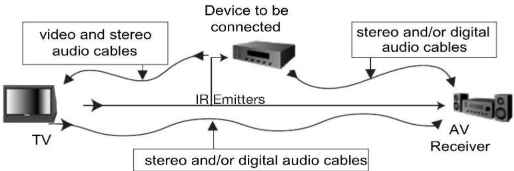
NetCommand is able to control many current audio and video devices by sending remote control signals from the TV to each device through IR emitters. Additionally, it is also able to learn the remote control signals used by most audio video devices not already in the TV's memory. NetCommand can automatically switch the TV and compatible or learned Audio/Video (A/V) Receivers to the correct input used with each device. It is important that the inputs on the TV and A/V receiver back panels match the NetCommand setup that is displayed on screen.
To simplify the installation of NetCommand, there is a step-by-step on-screen NetCommand Setup procedure in this chapter, which details the type and brands of devices you are connecting to the TV. The NetCommand Setup also assigns preset TV and A/V receiver inputs for each device. You should connect each device to the TV input (both audio and video) and to the A/V receiver (audio) as shown in the figure below. If you connect devices to inputs other than the ones shown as presets, you must change the NetCommand setup accordingly. See the Edit NetCommand information starting on page 47.
flowchart
graph LR
    TV["TV"] -->|video and stereo audio cables| Device["Device to be connected"]
    Device -->|stereo and/or digital audio cables| AV["AV Receiver"]
    Device -->|IR Emitters| Device
    AV -->|stereo and/or digital audio cables| Device
The following charts show which preset inputs you should use on the TV and A/V receiver.
Chart 1 shows the default TV inputs existing in NetCommand.
Chart 2 shows the A/V receiver inputs used by A/V receiver models already known by NetCommand.
| Chart 1 | |
| NetCommand Default Device Audio and Video Outputs to TV Inputs | |
| Cable for CableCARDTM Service | ANT-1 |
| Antenna/Cable (digital/analog) | ANT-1 if primary viewing source, ANT-2 if secondary viewing source |
| Cable box | COMPONENT-1 |
| VCR | Input-1 |
| Satellite Receiver (SAT) | Input-2 |
| Camcorder | Input-3 (on front panel) |
| DVD Player | COMPONENT-2 |
| PC | HDMI-2 |
| Chart 2 | Mitsubishi 1 | Mitsubishi 2 | Bose | Denon | Integra | Kenwood | Marantz | Pioneer 1 | Pioneer 2 | Rotel | Sony | Yamaha 1 | Yamaha 2 |
| ModelM-VR800 &M-VR1000 | ModelM-VR900 &M-VR700 | ModelLifestyle @28 | ModelAVR-2700 | ModelDTR-9.1 | ModelVR-2080 | ModelSR8200 | ModelVSX-D557 | ModelVSX-49TX | ModelRSX-1065 | ModelSTR-DE825 | ModelRV-X2095 | ModelRX-V2200 | |
| Device Audio Output to AV Receiver Inputs by Name | |||||||||||||
| VCR | VCR 1 VCR | VCR VCR-1 | Video 1 Video | VCR1 | VCR/Tape | VCR 1/DVR | Video 2 | Video 1 | VCR 1 | VCR 1 | |||
| Satellite Receiver | Aux | Cable/DBS | AUX | CD | Video 3 | Video 3 | DSS | CD | SAT | Video 4 | TV/DBS | TV/DBS | D-TV/LD |
| DVD Player | DVD | DVD | (built-in) | DVDVDP | DVD | Video 4 | DVD | LD/SAT | DVD/LD | Video 5 | TAPE/MD | CD | DVD |
| TV Monitor Output (& Digital Audio) | TV | TV | TV | TV/DBS | Video 4 | Video 4 | TV | DVD/TV | TV | Video 1 | DVD/LD | DVD/LD | CBL/SAT |
After using NetCommand Setup, you may go to the NetCommand menu at any time to change the inputs you used for connecting each device, custom name devices, add devices not included in the presets above or delete devices no longer used. See Edit NetCommand. See Helpful Hints at the end of this chapter for additional information on device setup.
CableCARD™ Technology
CableCARD Technology
CableCARD is a nationwide system standard that allows your local cable TV provider to supply you with an access card customized to your account. This card allows your TV to receive, decode and unscramble the premium digital channels included in your cable TV subscription without the use of a cable box. It also allows your cable provider to automatically update and change your subscription. When you move to a new cable provider's area, you simply return the CableCARD to the original cable provider and get a new card from your new cable provider.
Please note that CableCARD is a new technology and your local cable provider may not currently be offering this service. As time passes, this system will become broadly supported by most cable providers.
The CableCARD system is “unidirectional” which means your cable provider can send updates to the access card and TV, however, the TV cannot send back signals such as requests for Video-On-Demand or Pay-per-View programs by remote control.
Digital cable channels authorized by the CableCARD will be available on the Firewire® IEEE 1394 network and can be shared by other products on the network. Some digital channels or programs may not be copied or recorded because of copy restriction limits set by the content owners or copyright holders.
The digital television is capable of receiving analog basic, digital basic and digital premium cable television programming by direct connection to a cable system providing such programming. A security card (CableCARD) provided by your cable operator is required to view encrypted digital programming. Certain advanced and interactive digital cable services such as video-on-demand, a cable operator's enhanced program guide and data-enhanced television services may require the use of a set-top box. For more information call your local cable operator.
Please see page 58 for instructions on how to insert the CableCARD.
Using a CableCARD
After inserting a CableCARD into the TV back panel CableCARD slot and powering On the TV, the initialization process begins. An initial screen will automatically display for a few minutes, with information that your Cable Provider will need in order to start service. Please write down this information before calling your cable provider.
Please call XYZ Cable at xxx-xxx-xxxx to activate cable service.
They will need these numbers: Host ID X-XXX-XXX-XXX-XXX CableCARD™ ID: X-XXX-XXX-XXX-XXX
See owner's manual for further information
An example of an initial screen is shown here. Your screen will display specific information from your cable provider and may not look like this screen.
If you were unable to record the information, you can press TV MENU on the remote and then enter the number 999 and the screen will re-display. You can also press DEVICE MENU when the CableCARD is the selected source and you will be able to select the startup application.
IMPORTANT
To use a CableCARD, the primary incoming cable must be connected to ANT-1 MAIN.
Connecting a Wall Outlet Cable or Cable Box
Wall Outlet Cable
(can be used with a CableCARD™)
Figure 1
It is very important to connect the incoming cable for your primary viewing source to ANT-1, especially for CableCARD™ use and to download TV Guide On Screen® listings.
- Connect the primary incoming coaxial lead cable to ANT 1/MAIN on the TV back panel.
- For an optional secondary antenna source, connect an antenna (or cable) to ANT 2/AUX.
- If you have subscribed to a CableCARD™ service, the CableCARD can now be inserted into the CableCARD SLOT. Using a Phillips screwdriver, remove the CableCARD cover screws. Insert the CableCARD, then replace the cover and screws. The top of the card should face in the direction the CARD TOP arrow indicates.
Additional CableCARD information is on page 20. Detailed TV Guide On Screen information is in the separate User's Manual.
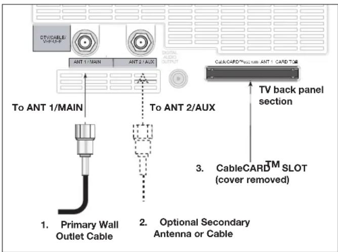
Figure 1. Wall Outlet Cable
IMPORTANT
Additional connection cables are not provided with the TV. They are available at most electronics stores.
Standard Cable Box
(analog cable box, other than an HDTV cable box, compatible with PIP)
Figure 2
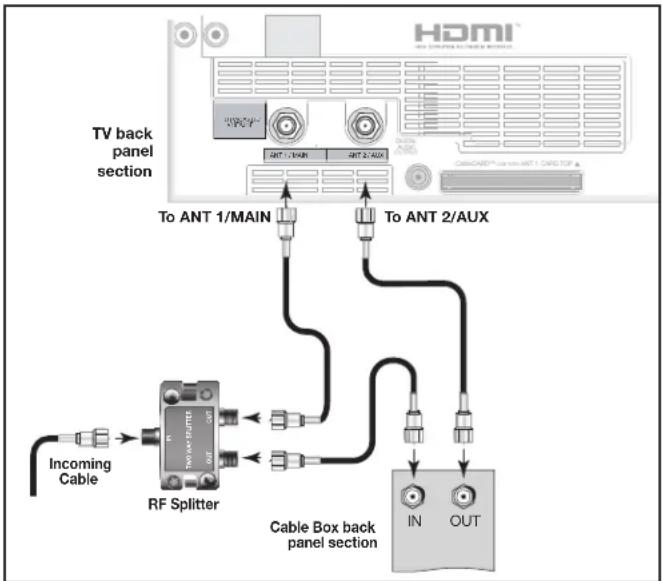
3 coaxial cables and one two-way RF splitter are required. These are not included with the TV.
Note: See page 29 to connect an HDTV cable box.
- Connect the incoming cable to IN on an RF splitter.
- Connect one coaxial cable from OUT on the RF splitter to ANT-1 MAIN on the TV back panel.
- Connect one coaxial cable from OUT on the RF splitter to IN on the analog cable box.
- Connect one coaxial cable from OUT on the cable box to ANT-2 AUX on the TV back panel.
- After the cable box is connected to ANT-2 AUX as shown, open NetCommand and go to the RF Connection for Cable screen and do the following:
a. Check the RF check box.
b. For antenna, select ANT-2.
c. For Channel, select the channel to which the TV must be tuned for your cable box. The default channel is 3.
When this setup is complete, you can use the TV remote control to change channels on the cable box.
flowchart
graph TD
    A["TV back panel section"] --> B["RF Splitter"]
    B --> C["Cable Box back panel section"]
    C --> D["IN"]
    C --> E["OUT"]
    B --> F["Incoming Cable"]
    B --> G["To ANT 1/MAIN"]
    B --> H["To ANT 2/AUX"]
    style A fill:#f9f,stroke:#333
    style B fill:#ccf,stroke:#333
    style C fill:#cfc,stroke:#333
    style D fill:#fcc,stroke:#333
    style E fill:#fcc,stroke:#333
    style F fill:#ffc,stroke:#333
    style G fill:#ffc,stroke:#333
    style H fill:#ffc,stroke:#333
Figure 2. Connecting a Cable Box
Note: To use a cable box connected to ANT-2 as shown above, you must make the noted NetCommand changes. The changes are required to change the NetCommand cable-box default connection (Component-1) to the actual connection (ANT-2).
Connecting an Antenna with a Single Lead or Antennas with Separate UHF and VHF Leads
Antenna with a Single Lead
(not for use with CableCARD™)
Figure 3
For antennas with flat twin leads
A 300-Ohm to 75-Ohm transformer is required. This is not included with the TV, but is available at most electronics stores.
- For an antenna with flat twin leads, connect the 300-Ohm twin leads to the 300-Ohm to 75-Ohm transformer.
- Push the 75-Ohm side of the transformer onto ANT-1 MAIN on the TV back panel.
For cable or antenna with coaxial lead
Connect the coaxial lead directly to ANT-1 MAIN on the TV back panel.
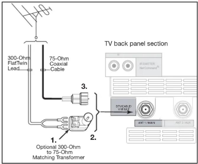
Figure 3. Connecting a Single Antenna
Antennas with Separate UHF and VHF Leads
Figure 4
A UHF/VHF combiner is required. This is not included with the TV.
- Connect the UHF and VHF antenna leads to the UHF/VHF combiner.
- Push the combiner onto ANT-1 MAIN on the TV back panel.
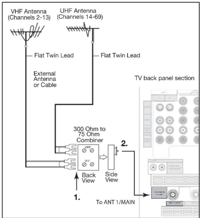
Figure 4. Connecting separate UHF and VHF Antennas
Mitsubishi strongly recommends you avoid using antennas with flat twin leads. Flat twin lead antenna wires are subject to interference which may adversely affect the performance of the TV. We recommend using coaxial antenna cable.
Connecting a VCR to an Antenna or Wall Outlet Cable Connecting VCR Audio and Video to the TV
VCR to an Antenna or Wall Outlet Cable (Audio & Video)
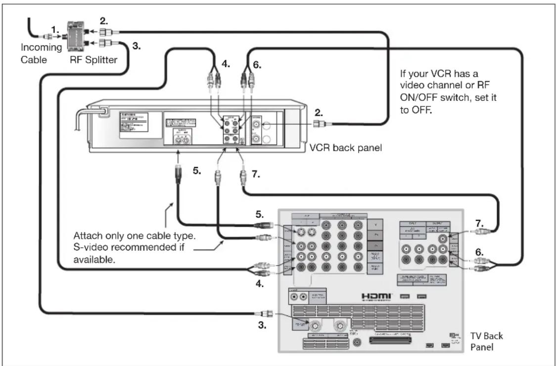
Figure 5 A two-way RF splitter, 3 coaxial cables, right and left audio cables and an S-Video or Video cable are required. These are not included with the TV.
- Connect the incoming cable or Antenna to IN on the RF splitter.
- Connect one coaxial cable from OUT on the RF splitter to ANTENNA IN on the VCR back panel.
- Connect one coaxial cable from OUT on the RF splitter to ANT-1 MAIN on the TV back panel. This connection also allows you to use the TV Guide On Screen® feature.
-
To use the TV speakers with the VCR, connect a set of audio cables from AUDIO OUT on the VCR back panel to INPUT-1 AUDIO-LEFT (MONO) and AUDIO-RIGHT on the TV back panel. The red cable connects to the R (right) channel and the white cable connects to the L (left) channel. If your VCR is mono (non-stereo), connect only the white (left) cable.
-
Connect either an S-Video or Video cable from VIDEO OUT on the VCR back panel to INPUT-1 VIDEO on the TV back panel. Only one type of video cable should be connected. S-Video is recommended, if available.
-
For NetCommand® controlled recordings (including TV Guide On Screen), connect a set of audio cables from AUDIO IN on the VCR back panel to RECORD OUTPUT/AUDIO-LEFT and AUDIO-RIGHT on the TV back panel. The red cable connects to the R (right) channel and the white cable connects to the L (left) channel.
-
Complete the NetCommand controlled recordings connections by connecting a Video cable from VIDEO IN on the VCR back panel to RECORD OUTPUT/VIDEO on the TV back panel.
flowchart
graph TD
    A["TV Back Panel"] --> B["Attach only one cable type. S-video recommended if available."]
    B --> C["VCR back panel"]
    C --> D["RF Splitter"]
    D --> E["Incoming Cable"]
    D --> F["2. RF Splitter"]
    D --> G["3. VCR back panel"]
    G --> H["1. Incomining Cable"]
    G --> I[4. 6. 7. 8. 9. 10. 11. 12. 13. 14. 15. 16. 17. 18. 19. 20. 21. 22. 23. 24. 25. 26. 27. 28. 29. 30. 31. 32. 33. 34. 35. 36. 37. 38. 39. 40. 41. 42. 43. 44. 45. 46. 47. 48. 49. 50. 51. 52. 53. 54. 55. 56. 57. 58. 59. 60. 61. 62. 63. 64. 65. 66. 67. 68. 69. 70. 71. 72. 73. 74. 75. 76. 77. 78. 79. 80. 81. 82. 83. 84. 85. 86. 87. 88. 89. 90. 91. 92. 93. 94. 95. 96. 97. 98. 99. 100.
Figure 5. Connecting a VCR to an Antenna or Wall Outlet Cable
Note:
NetCommand® will assume your VCR is connected to inputs as shown on this page. If you use any other inputs for your VCR or add a second VCR, this change must match in the NetCommand system. See Edit NetCommand... in Chapter 3 for more information.
Connecting a VCR to a Cable Box (Audio & Video)
VCR to a Cable Box (Audio & Video)
Figure 6
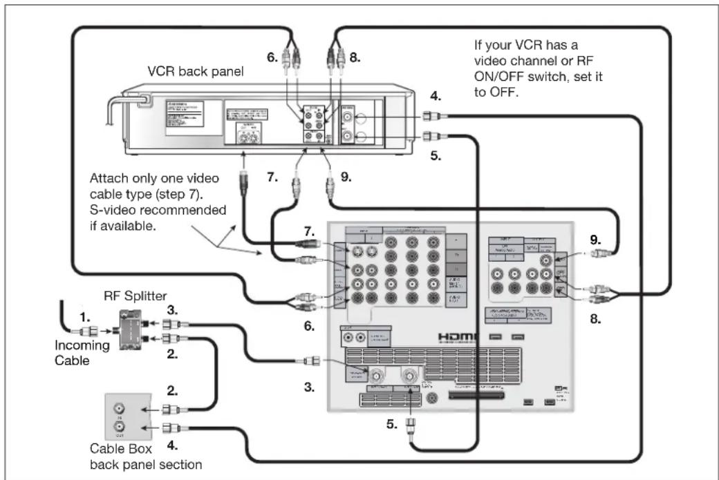
A two-way RF splitter, 4 coaxial cables, right and left audio cables and an S-Video or Video cable are required. These are not included with the TV.
- Connect the incoming cable to IN on the RF splitter.
- Connect one coaxial cable from OUT on the RF splitter to ANTENNA IN on the cable box back panel.
- Connect one coaxial cable from OUT on the RF splitter to ANT-1 MAIN on the TV back panel. This connection also allows you to use the TV Guide On Screen® feature.
- Connect one coaxial cable from OUT on the cable box to ANTENNA IN on the VCR back panel.
- Connect one coaxial cable from ANTENNA OUT on the VCR back panel to ANT-2 AUX on the TV back panel (optional).
- To use the TV speakers with the VCR, connect a set of audio cables from AUDIO OUT on the VCR back panel to INPUT-1 AUDIO-LEFT (MONO) and AUDIO-RIGHT on the TV back panel. The red cable
connects to the R (right) channel and the white cable connects to the L (left) channel. If your VCR is mono (non-stereo), connect only the white (left) cable.
-
Connect either an S-Video or Video cable from VIDEO OUT on the VCR back panel to INPUT 1 VIDEO on the TV back panel. Only one type of video cable should be connected. S-Video is recommended, if available.
-
For NetCommand® controlled recordings (including TV Guide On Screen), connect a set of audio cables from AUDIO IN on the VCR back panel to RECORD OUTPUT/AUDIO-LEFT (MONO) and AUDIO-RIGHT on the TV back panel. The red cable connects to the R (right) channel and the white cable connects to the L (left) channel.
-
Complete the NetCommand controlled recordings and TV Guide On Screen connections by connecting a Video cable from VIDEO IN on the VCR back panel to RECORD OUTPUT/VIDEO on the TV back panel.
Note: With this connection configuration, it is possible to view live cable programs through the VCR. For best picture quality, however, always view live cable programs directly from the cable box instead of the VCR.
flowchart
graph TD
    A["VCR back panel"] -->|6.| B["Attach only one video cable type (step 7). S-video recommended if available."]
    A -->|8.| C["If your VCR has a video channel or RF ON/OFF switch, set it to OFF."]
    A -->|4.| D["Home"]
    A -->|5.| E["RF Splitter"]
    A -->|7.| F["Cable Box back panel section"]
    A -->|9.| G["Home"]
    A -->|6.| H["Incoming Cable"]
    A -->|3.| I["Home"]
    A -->|2.| J["Home"]
    A -->|1.| K["Home"]
    A -->|4.| L["Home"]
Figure 6. Connecting a VCR to a Cable Box
Note: NetCommand® will assume your VCR is connected to inputs as shown on this page. If you use any other inputs for your VCR or add a second VCR, this change must match in the NetCommand system. See Edit NetCommand... in Chapter 3 for more information.
Connecting an A/V Receiver (Stereo System) Connecting a Satellite Receiver or Other Device with S -Video
A/V Receiver (Stereo System)
Figure 7 A digital audio cable and stereo audio cables are required. These cables are not included with the TV.
1. To connect an analog A/V receiver:
Connect a set of stereo audio cables from OUTPUT AUDIO 2 on the TV back panel to the TV AUDIO INPUT on the back of the A/V receiver. The red cable connects to the R (right) channel and the white cable connects to the L (left) channel.
2. To connect a digital A/V receiver with Dolby® Digital surround sound:
Connect one end of the digital audio cable supplied with the TV to DIGITAL AUDIO on the back of the TV. Connect the other end to the COAXIAL DIGITAL INPUT on the back of the A/V receiver.
Check the A/V receiver's Owner's Guide for information concerning use of the digital input and switching between digital sound and analog stereo sound from the TV.
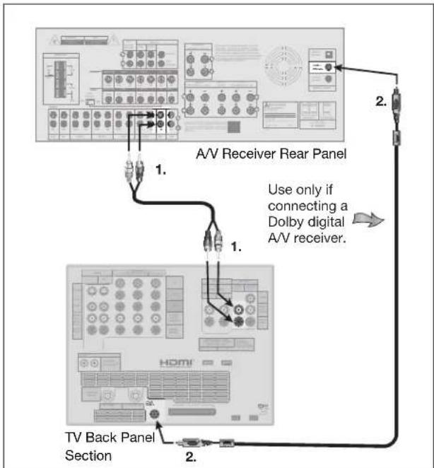
Figure 7. Connecting an A/V receiver
Note: On rare occasions, an HDMI signal may be copy-restricted and cannot be output from the TV as a digital signal. To hear these copy-protected signals through the A/V receiver, use connections for analog A/V receivers.
MP3 audio from memory cards cannot be connected to digital audio. To listen to MP3 playback from the TV MediaCommand memory card player through your A/V receiver, use the connections for an analog A/V receiver.
Satellite Receiver or Other Device with S-Video
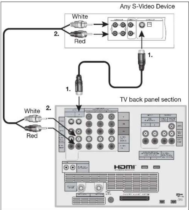
Figure 8 An S-Video cable and audio cables are required. These are not included with the TV.
-
Connect an S-Video cable from VIDEO OUT on the satellite receiver back panel to INPUT-2 S-VIDEO on the TV back panel.
-
Connect a set of audio cables from AUDIO OUT on the satellite receiver back panel to INPUT-2 AUDIO on the TV back panel. The red cable connects to the R (right) channel and the white cable connects to the L (left) channel.
Note: Refer to the Satellite Receiver Owner's Guide for Dish Antenna connections
flowchart
graph TD
    A["White"] --> B["Red"]
    C["White"] --> D["Red"]
    E["White"] --> F["Red"]
    G["TV back panel section"] --> H["Home Studio 1"]
    G --> I["Home Studio 2"]
    J["Any S-Video Device"] --> K["Control Panel 1"]
    J --> L["Control Panel 2"]
    M["HDMI"] --> N["Display Panel 1"]
    M --> O["Display Panel 2"]
Figure 8. Connecting a Satellite Receiver with S-Video
Note: NetCommand® will assume you connected your Satellite Receiver to Input-2. If you add a second Satellite Receiver or use any other inputs for your Satellite Receiver, this change must match in the NetCommand system. See Editing NetCommand Setup in Chapter 3 for more information.
Connecting a DVD Player with Component Video Connecting a DVI Device
DVD Player with Component Video
Figure 9 Component video cables and audio cables are required. These are not included with the TV.
-
Connect the Component Video cables from Y/Pr/Pb VIDEO OUT on the back of the DVD player to COMPONENT-2 on the TV back panel, matching the correct connection:
-
Y to Y (Green)
- Pr to Pr (Red)
-
Pb to Pb (Blue)
-
Connect a set of audio cables from AUDIO OUT on the back of the DVD player to COMPONENT-2 AUDIO Input on the TV back panel. The red cable connects to the R (right) channel, and the white cable connects to the L (left) channel.
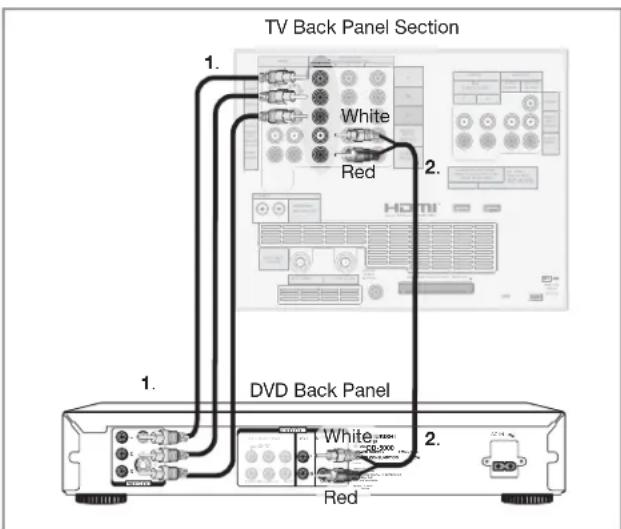
Figure 9. Connecting a DVD Player with Component Video
Note: NetCommand® assumes you connected your DVD player to Component-2. If you add a second DVD or use any other inputs for your DVD, this change must match in the NetCommand system. See Edit NetCommand... in Chapter 3 for more information.
IMPORTANT
See Appendix B for component video signal compatibility information.
For digital audio connections to your A/V receiver, see your DVD player and A/V receiver Owner's Guides.
DVI Device
Figure 10
A DVI-to-HDMI cable or DVI/HDMI adaptor and HDMI cable and audio cables are required. These are not included with the TV. They may be available at your local electronics retailer.
- Connect the DVI-to-HDMI cable (recommended) or HDMI cable with DVI/HDMI adaptor from the DVI device's back panel to the TV back panel.
NOTE: If you are using a DVI/HDMI adaptor, it is important to connect the adaptor to the DVI device for best performance. - Connect a set of audio cables from AUDIO OUT on the DVI device back panel to the INPUT/DVI Analog Audio on the TV back panel. The red cable connects to the R (right) channel, and the white cable connects to the L (left) channel.
NOTE: The HDMI connection supports copy protection (HDCP). Some devices require connecting to an analog input first, in order to view on-screen menus and select DVI as the output. Please review your equipment instructions for DVI connectivity and compatibility.
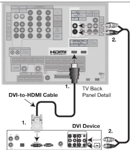
Figure 10. Connecting a DVI Device

CAUTION: To ensure continued FCC compliance, the user must use a shielded video interface or HDMI cable with bonded ferrite cores at both ends when using the PC input.
Connecting an HDTV Cable Box or Satellite Receiver with Component Video Connecting an HDMI Device
HDTV Cable Box or Satellite Receiver with Component Video
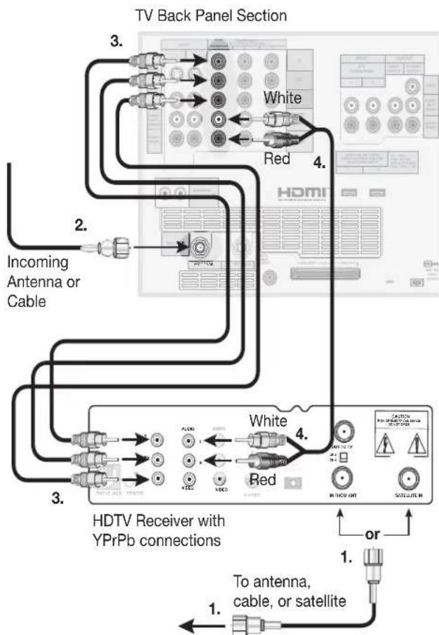
Figure 11 A coaxial splitter, RCA component video cables, and audio cables are required. These are not included with the TV.
-
Connect the outside antenna, cable, or satellite to ANT or SATELLITE IN on the cable box or satellite receiver. See your device's owner's guide for instructions and cable compatibility.
-
Connect the incoming terrestrial antenna or cable (not satellite) to ANT-1 on the TV back panel (a coaxial splitter, available at most electronic supply stores, may be required to complete this installation).
flowchart
graph TD
    A["To antenna, cable, or satellite"] --> B["HDTV Receiver with YPrPb connections"]
    B --> C["3. White"]
    B --> D["4. Red"]
    B --> E["2. Incoming Antenna or Cable"]
    C --> F["3. Red"]
    D --> G["4. White"]
    E --> H["2. Incoming Antenna or Cable"]
    F --> I["HDVI"]
    G --> J["HDVI"]
    H --> K["HDVI"]
    style A fill:#f9f,stroke:#333
    style B fill:#ccf,stroke:#333
    style C fill:#cfc,stroke:#333
    style D fill:#fcc,stroke:#333
    style E fill:#cff,stroke:#333
    style F fill:#ffc,stroke:#333
    style G fill:#ffc,stroke:#333
    style H fill:#ffc,stroke:#333
    style I fill:#cfc,stroke:#333
    style J fill:#cfc,stroke:#333
    style K fill:#cfc,stroke:#333
Figure 11. Connecting an External HDTV Receiver with Component Video Connections
- Connect RCA-type cables from the YPrPb outputs on the HDTV receiver to Component-1 on the TV back panel, matching the correct connections:
HDTV Receiver to TV Back panel
- Y to Y
- Pr to Pr
- Pb to Pb
- Connect L (left) and R (right) audio cables from the DTV receiver to Component-1 AUDIO on the TV back panel.
- If you are using a satellite receiver, you must change the input through NetCommand. Open the NetCommand Connection for [device] screen (see page 49) to make the change.
Note: To receive the benefits of a digital A/V receiver, connect your cable box or satellite receiver's digital audio out to a digital input on your digital A/V receiver.
HDMI Device
Figure 12 An HDMI-to-HDMI cable is required. This is not included with the TV. It may be available at your local electronics retailer
Connect an HDMI cable from the TV back panel to the HDMI device output. HDMI devices provide video and audio through this cable, so no other connection is required. You can connect two HDMI devices to the TV back panel through the HDMI connections.
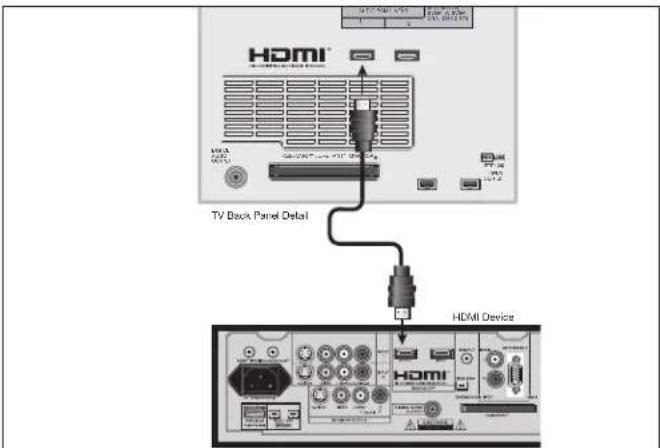
Figure 12. Connecting an HDMI Device
Note: To use the benefits of digital surround sound from th HDMI device, connect the digital audio output of the HDMI device directly to the A/V receiver.
Connecting a Computer with an HDMI or DVI Monitor Output
Computer with an HDMI Monitor Output
Figure 13 An HDMI-to-HDMI cable is required. This is not included with the TV. It may be available at your local electronics retailer
Connect an HDMI cable from HDMI 2 on the TV back panel to the PC's HDMI output. HDMI devices provide video and audio through this cable, so no other connection is required.
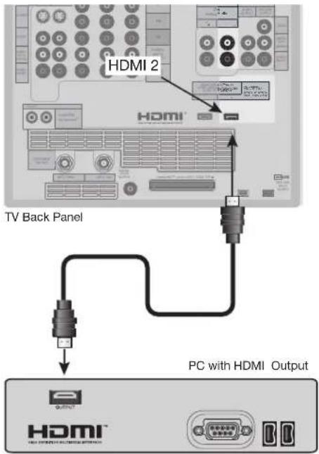
Figure 13. Connecting a Computer with an HDMI Monitor Output
IMPORTANT
To view PC video on the TV, you must activate the PC option in NetCommand. You can do this during initial NetCommand setup (in the Device Setup screen), or at any time afterwards by using the NetCommand Add function.

CAUTION: To ensure continued FCC compliance, the user must use a shielded video interface or HDMI cable with bonded ferrite cores at both ends when using the PC input.
Computer with a DVI Monitor Output
Figure 14 A DVI-to-HDMI cable or DVI/HDMI adaptor and HDMI cable and audio cables are required. These are not included with the TV. They may be available at your local electronics retailer.
- Connect the DVI-to-HDMI cable (recommended) (or DVI/HDMI adaptor with an HDMI cable) from the PC DVI output to HDMI 2 on the TV back panel.
NOTE: If you are using a DVI/HDMI adaptor, it is important to connect the adaptor to the DVI device for best performance.
- Connect a set of audio cables from AUDIO OUT on the PC back panel to INPUT/DVI Analog Audio 2 on the TV back panel. The red cable connects to the R (right) channel, and the white cable connects to the L (left) channel.
NOTE: The HDMI connection supports copy protection (HDCP). Some devices require connecting to an analog input first, in order to view on-screen menus and select DVI as the output. Please review your equipment instructions for DVI connectivity and compatibility.
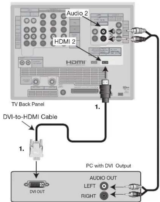
flowchart
graph TD
    A["TV Back Panel"] -->|1.| B["PCI with DVI Output"]
    B --> C["DVI OUT"]
    C -->|1.| D["DVI-to-HDMI Cable"]
    D --> E["Audio 2"]
    E --> F["HDMI 2"]
    F --> G["PC with DVI Output"]
    style A fill:#f9f,stroke:#333
    style B fill:#ccf,stroke:#333
    style C fill:#cfc,stroke:#333
    style D fill:#fcc,stroke:#333
    style E fill:#ffc,stroke:#333
    style F fill:#cff,stroke:#333
    style G fill:#ffc,stroke:#333
Figure 14. Connecting a Computer with DVI Monitor Output
Connecting the IR Emitter NetCommand®
IR Emitter NetCommand®
Figure 15
An IR emitter cable is included with the TV.
The emitters connected to these jacks are used by the NetCommand system to control other devices such as VCRs, DVD players, Cable boxes and Satellite receivers.
- Connect the plug end of the supplied IR Emitter Cable to either one of the IR Output NetCommand jacks on the TV back panel.
- Run the cable for each of the emitter ends under, along side or over the top of each device to be controlled to the area of the front where the remote control sensor is located.
- Place the emitter end in front of the remote control sensor of the device to be controlled. The emitter bulb should face the remote control sensor. This bulb emits infrared light in a cone shaped pattern. The bulb needs to be placed far enough from the remote control sensor to allow the cone pattern to include the sensor.
The remote control sensor is usually behind the plastic window of the front display panel. It is sometimes visible when you look through the display plastic using a flashlight and is normally a round or square cutout behind the plastic. If you cannot see the sensor and the device's Owner's Guide does not specify the location, you can find it by using the device's remote control.
a. Hold the remote about 1/2 inch from the front of the device. Starting from one end of the display window plastic, press the POWER button.
b. If the device does not respond, move the remote control 1 inch toward the center and try again.
c. Repeat this until the device responds.
d. Note this location and then start over from the other end of the display window plastic, repeating until the device responds again.
The remote control sensor will be somewhere between these two positions. This is usually enough accuracy for the placement of the IR emitters.
- With some devices, the emitter works better facing downward from the top of the device. Some experimentation may be needed.
- The emitter end being used can be secured in place using double stick tape.
- If you are not going to be using all emitter ends, place the unused ends behind the devices so that they cannot send signals to the remote control sensors.
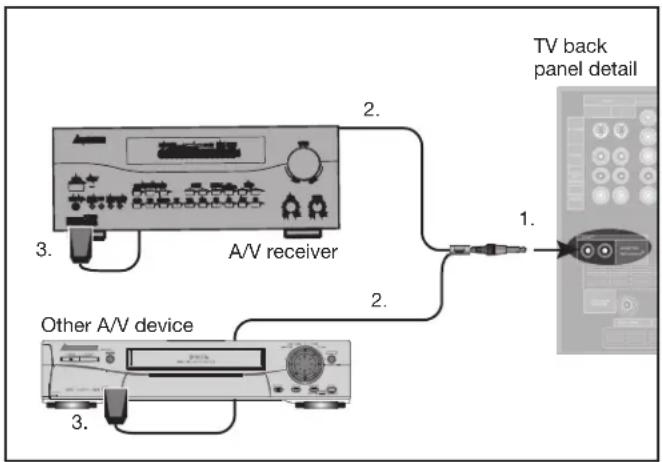
Figure 15. Connecting IR Emitter NetCommand
IMPORTANT
If a single emitter end can be placed in a position that will operate more than one device, do not use a separate emitter end for the additional device. A single device receiving remote control signals from too many emitters or remote controls may not respond at all.
Connecting Compatible IEEE 1394 Devices
Compatible IEEE 1394 Devices
It is possible to connect devices to the TV that have IEEE 1394 connectors but are not compatible with the TV or with the NetCommand ^® control system. Areas of compatibility to consider are:
1. Digital Video Signals
The TV is able to decode MPEG2 video. Other types of digital video, such as DV video provided by some camcorders, must be decoded by the source device and sent to the TV as analog video, or S-video. If the camcorder uses a compatible digital control system, the IEEE 1394 cable can still provide control for the camcorder while the TV is viewing the analog video or S-Video signals.
2. Digital Audio Signals
When received with video signals, the TV is able to decode Dolby Digital signals and MPEG audio signals. Other types of digital audio as provided by some digital recording devices, such as MP3 audio and DTS audio, cannot be decoded by the TV when received over IEEE 1394
The TV may not be able to pass incompatible digital audio signals on the coaxial digital audio output, however these signals may pass on the IEEE 1394 cable to other devices.
3. Digital Control Signal
The TV is able to act as the control center for IEEE 1394 audio/video devices, such as VCRs, A/V Discs, tuners, cable boxes and amplifiers that are compatible with the following IEEE 1394 control standards.
- EIA-775 is designed for tuning devices such as cable boxes allowing the device to send simple graphics. However, this standard does not allow the TV to control the cable box by IEEE 1394.
- AV/C (Audio Video Control) is designed to provide basic controls such as play, stop, channel selection and volume, as appropriate for the device.
Some devices may be a combination of two or more types of devices. For example, there may be a recording device that is also a tuning device. Each portion of the device is called a sub-unit. When you select a device on the Device Selection menu that has sub-units, a pop-up menu will appear so you can select which sub-unit section you wish to use.
When Connecting IEEE 1394 Devices
- Do not loop the last device in the chain back to the TV. When the device chain is looped, the TV may not be able to work with the other devices.
- Place devices that have only a mechanical (two-position) power switch at the end of the chain or leave the power switch in the On position. When turned Off, IEEE 1394 signals may not be able to pass through the device to other devices.
- Place devices with the slowest communication speed at the end of the chain. Sometimes the communication speed will be marked near the IEEE 1394 connector with an "S" number. The higher the number, the faster the communication speed. This TV has a communication speed of S400. Devices with slow communication speed can interfere with IEEE 1394 signals from faster devices. When using NetCommand to set up a digital recording between a faster and slower device, the slower device should be the source and the faster device should be the recorder.
- Do not use an IEEE 1394 cable longer than 15 feet between each device.
- This TV is an IEEE 1394a device. It can be used with a 1394b system when an IEEE 1394a to 1394b convertor is used. 1394b systems enable longer distance and multi-room applications.
Connecting Compatible IEEE 1394 Devices, continued
Connection Styles
There are two different connection styles that can be used when connecting IEEE 1394 devices. Use the style that fits your network of audio/video products.
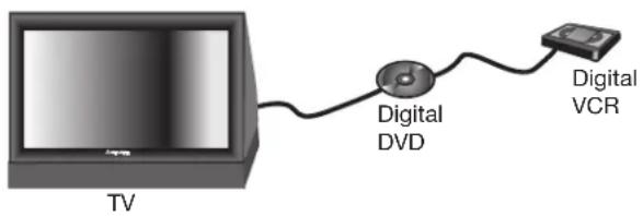
Direct Device-To-Device Style
The IEEE 1394 offers you the capability to chain devices, unlike previous audio and video connections where you had to individually connect each device directly to the TV. For example, you can connect your D-VHS to your 1394 DVD Player and then connect the 1394 DVD Player to the TV. The resulting IEEE 1394 chain will allow you to add more devices to the chain. You will be able to see each video device on the TV's Device Selection Menu and send information from any IEEE 1394 device to other compatible devices.
Hub Connection Style
The IEEE 1394 also offers you the capability to connect your devices using the TV as a hub within the audio/video network. Each device can send information, which may include audio and video, to any other device in the network.
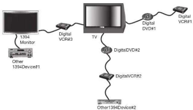
flowchart
graph LR
    A["1394 Monitor"] --> B["Digital VCR#3"]
    C["Other 1394Device#1"] --> B
    B --> D["TV"]
    D --> E["Digital DVD#2"]
    D --> F["DigitalVCR#2"]
    E --> G["Digital DVD#1"]
    F --> H["Digital VCR#1"]
    I["Other1394Device#2"] --> F
4-Pin Style vs. 6-Pin Style Connectors
There are two different types of connectors used for IEEE 1394 terminals and cables, a 4-pin and a 6-pin style.
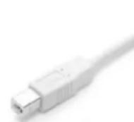
4 pin connector
The 4-pin connector sends digital audio signals, digital video signals and digital control signals back and forth between devices. Your TV has three 4-pin type connection jacks available. One is on the front panel and two are on the back.
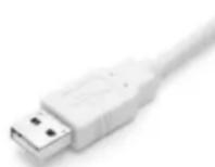
6 pin connector
The 6-pin connector is capable of sending the same digital audio, video and control signals as the 4-pin connector, but the 6-pin connector is also able to send low voltage electrical power. This TV does not have 6 pin connectors.
The purpose of this low voltage electrical power is to provide the needed operating power to a device that is not connected directly to the household AC power such as a camcorder. A device with a 6-pin connector can send this electrical power to another device, or receive electrical power from another device, or simply use a 6-pin connector without using the two additional pins.
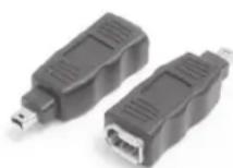
6 pin to 4 pin adaptor
A 6-pin connector cannot be connected directly to a 4-pin jack, and vice versa. To connect a 6-pin device to a 4-pin device, you will need to obtain a 6-pin to 4-pin adaptor or adaptor cable. These cables are available from electronic and computer stores.
When connecting a 6-pin device (such as a camcorder) to the TV, (if it is designed to receive electrical power from another 6-pin device) you will need to connect the camcorder directly to the household AC, or use the camcorder's battery for power. If this is not possible, then the camcorder will need to be connected directly to another 6-pin device in the network that can provide the electrical power.
Helpful Hints
Q. My VCR (or other device) does not have two sets of stereo audio outputs. How can I connect this device's audio to both the TV and the A/V Receiver?
A. Connect the single set of stereo audio outputs to the TV only. Use Edit NetCommand® to change the setup of this device. In the Connection screen of "Change" make sure both audio and video for the TV input are check marked and neither the audio or the video for the AVR input are check marked. This will allow the NetCommand system to use the TV outputs to transfer the device's audio to the A/V Receiver. See Edit NetCommand in the next chapter for details.
Q. I have both the TV stereo audio output and TV digital audio output connected to the same input designations on my A/V Receiver. How do I switch between analog audio and digital audio?
A. In most setups, analog audio is also output as digital audio, so no switching is required, and there is no need to connect the analog output. In some circumstances, however, you may also need analog audio from the TV. For example, MP3 audio is only output in analog format, so you must connect the TV's analog AUDIO OUTPUT to the A/V Receiver if you want to hear MP3 audio through the A/V receiver. Refer to your A/V Receiver user's guide to find out how analog/digital audio switching works.
- If your A/V Receiver's remote control has an Analog/Digital Audio key, you can use the GUIDE key with the following models to control switching:
Mitsubishi M-VR900 Integra DTR-9.1
Denon AVR-2700 Kenwood VR-2080
To make the switch, press the Device key on the TV's remote control, and from the Device Selection menu, press the Audio key. Then, with the A/V Receiver highlighted, press the GUIDE key to make the switch.
- If you have some other A/V Receiver model, use the TV's learn function to learn the analog/digital audio code for the GUIDE key. Follow the instructions above for using the GUIDE key.
- If your A/V Receiver has an Analog/Digital selection key on the front panel only, and not on the remote, then your only option is to use that key to perform switching.
Q. The front panel of my A/V Receiver is too tall or too convex for the IR emitter signal to reach the remote control sensor of the A/V Receiver. What can I do?
A. There are several possible solutions.
- Mount the IR Emitter on the top, front edge of the A/V Receiver over the remote control sensor. Use tape to secure it in place.
- Mount the IR Emitter on the underside of the shelf above the A/V Receiver (if the A/V Receiver is in a cabinet). Use double sided tape to secure it in place.
- Some small stick-on emitters from other manufacturers may be compatible with this TV's IR Emitter jacks. These may be used instead of the supplied IR Emitters.
Q. I occasionally need to see the menu from my A/V Receiver. How can I connect it to the TV for this purpose?
A. You can connect the video output of the A/V Receiver to an unused input on the TV. Then use Edit NetCommand to "Add" this as an "Other" device, not an A/V Receiver. On the "Connection" screen, indicate which TV input was used and check mark the video box. Make sure the TV input audio box and both the audio and video boxes for the AVR input are not check marked. You should also name this device so you can easily identify it on the Device Selection Menu. You can also use Input 3 on the front panel.
Q. I have a high definition receiver I would like to connect and it also has an S-video output I would like to be able use as well. Is there any way to connect this receiver both ways?
A. Yes, this item will appear twice in the Device Selection Menu. Just add this unit once using the Component-1 and once using one of the S-video inputs. Make sure you indicate that this is the same manufacturer for both. We suggest that you connect stereo audio outputs with the S-video to the TV so that you do not need to use two inputs on the A/V Receiver. If this is a NetCommand compatible HDTV receiver and HD or SD outputs can be switched by remote control, see Edit NetCommand in the next chapter for NetCommand control of this feature.
Chapter ...

NetCommand® Setup and Editing
NetCommand® Introduction 38
Using the Remote Control with NetCommand® 39
NetCommand® Setup On-Screen Buttons. 40
3D Graphical ▶ Monetini System 41
NetCommand® Initial Setup 42
Edit NetCommand®: Add an A/V Receiver 45
Edit NetCommand®: Add Devices 48
Edit NetCommand®: Change or Delete Devices .....52
NetCommand® Introduction
Welcome To NetCommand
NetCommand makes your TV the heart of your Home Theater
NetCommand® is an intelligent control system that makes your Mitsubishi TV the heart of your home theater. With NetCommand, the TV sends signals to the other devices in the system, telling them to play, record, change inputs, adjust volume, change channels and many more functions. All of this is accomplished with one remote control and without changing control layers.
IR Learning and IEEE 1394 Support
The IR “Learning” feature of NetCommand allows the TV to learn the remote control signals for new devices that the TV is not preprogrammed to operate. NetCommand® also includes the capability to control IEEE 1394 devices by sending control signals on a FireWire® cable.
Using NetCommand is completely optional
When you first turn on the TV, the NetCommand Setup Wizard launches. If you decide to use NetCommand, follow the on-screen instructions. If you choose not to use it right away, simply quit the Setup Wizard and NetCommand will remain inactive. Later, if you decide to use NetCommand, you can easily access the Setup Wizard.
NetCommand and Levels of Control
When you set up NetCommand, you decide how much control you want the TV to have over your home theater system. You have the choice of performing a basic, limited, or complete NetCommand setup.
- Basic Setup
In a basic setup, NetCommand will:
◇ automatically switch to the correct TV input when you want to view programming from a different device. All you do is select the device from the on-screen device selection menu. This saves you from having to search for the correct input every time you want to change devices. Unused inputs are automatically deactivated so that you don't see them in the menu.
◇ show an on-screen icon for each device connected to the TV so you always know what devices are available.
Note that with a basic setup, you still need to use the remote control specific to each device.
- Limited Setup
In a limited setup, you get the benefits of the basic setup plus NetCommand control over the specific devices you have chosen. Use this type of setup if you:
only want NetCommand to control a few devices, such as the TV, a playback device (like a DVD player), and a cable box. With this setup, you can use the TV's remote to control these devices.
◇ want to use TV Guide On Screen® to control your cable box and VCR and/or A/V disc. After performing this setup, you can use the TV's remote to control these devices.
- Full Setup
Perform a full setup if you want NetCommand to:
◇ control a surround sound A/V receiver.
◇ automatically change input selections for the A/V receiver.
◇ control all devices with the TV's remote, including the A/V receiver.
NetCommand Helps You Manage Your Home Theater
With the NetCommand Review screen you can:
• view a summary of all devices connected to the TV and the input used for each device.
- deactivate or turn off unused input connections; reactivate or turn them on.
If you need to change your setup, the NetCommand sub-menu lets you easily
- add new devices.
- deleted devices you have disconnected.
- change device and input selections.
Using the Remote Control with NetCommand®
Below is a list of several manufacturers' devices tested and shown to be compatible with NetCommand. These devices can be controlled without changing the setting of the remote control from TV to another product. NetCommand may be able to operate additional models since many manufacturers use the same control signals to operate some or all of the models they offer. This chart lists only the models that have been tested with NetCommand. The NetCommand Learning feature is able to learn the remote control signals of most Audio Video devices. For devices not listed in the table, or if your device does not operate using the same remote control as the models listed below, use the learning feature by selecting "Other" at the [Device] screen. See the Edit NetCommand section of this Guide.
NOTE: There are many different types of remotes and not all of them may be compatible with the learning feature. Bright light near the TV screen can also adversely affect the learning feature. If it is not possible to learn a device, you will need to use the original remote control of the device, or program the TV remote to operate these devices in the traditional manner.
NetCommand Pre-Memorized Devices
| DEVICE | ||||||
| MANUFACTURER | A/V receiver Cable Box | SAT Satellite | Receiver | DVD Player VCR | ||
| Mitsubishi M-VR800, | M-VR900 | SR-HD5 DD-6000, DD-8020 | HS-U795, HS- | U778 | ||
| Bose Lifestyle® 28 Lifestyle® 28 | ||||||
| Denon AVR-2700 | ||||||
| Echostar 6000 | ||||||
| Funai F260LA | ||||||
| General Instruments | CFT2200 | |||||
| Hitachi DV-P415U | VT-FX665A | |||||
| Hughes | HIRD-E45,HIRD-E86 | |||||
| Integra | DTR-9.1 | DPS-9.1 | ||||
| Jerrold | Not specified | |||||
| JVC | XV-S65GD | HR-VP 650U | ||||
| Kenwood | VR2080 | |||||
| Marantz | SR8200 | |||||
| Microsoft | XBox^TM (requires the DVD kit from Microsoft) | |||||
| Motorola | DCT2244 | |||||
| Panasonic | TU-HDS20 | DVD-A310 | PV-8662 | |||
| Philips | VR620CAT | |||||
| Pioneer | VSX-D557,VSX-49TX | DV-414 | ||||
| RCA | DRD480RE,DTC-100 | |||||
| Rotel | RSX-1065 | |||||
| Scientific Atlanta | 8600 | |||||
| Sharp | VC-H810U | |||||
| Sony STR-DE825 | SAT-A55 | DVP-S500D, PlayStation® 2(Playstation® 2 requires the DVD Remote Controller kit from Sony; DVD Player software disc version 2.10) | SLV-778HF | |||
| Toshiba | DTS-3000 | SD-9200, SD-5109 | W-717 | |||
| Yamaha | RX-V2095,RX-V2200 | DVD-S520, DVD-C996 | ||||
| Zenith | DTV1080 | |||||
NetCommand® Setup On-Screen Buttons
To use the TV's NetCommand feature, you need to provide some detailed information during the setup of your Mitsubishi TV. You must define the manufacturer of the devices that are connected to the television, or learn the IR code remote control signals for the device connected. For each device, the input to the TV and A/V receiver, and the names for the device are pre-set during Initial NetCommand setup. You may change those inputs or names using the Edit NetCommand or Learn screens. The buttons described below will help you navigate the screens.
On your remote control, the ADJUST ▶ or ▶ buttons allow you to navigate left and right to different selections on the screen. The ADJUST ▶ or ▶ buttons allow you to:
- Change the radio button
- Change current text box selection
- Navigate up and down on the screen
The ENTER button allows you to:
- Confirm the selected character when naming a device
- Add or delete check marks in check boxes
- Select on-screen buttons to change screens
Text Box
Press ADJUST ▲ or ▼ to make a selection.
Check Box

Check marks indicate the item or input is added or turned On. Press ENTER when the Check box is highlighted to add or delete a check mark. When viewing the Review screen, a Check box reflects which devices are turned On or Off, or connected to the TV.
Radio Buttons

The setting changes when one of the choices is highlighted.
Control Buttons
Much like the software on your computer, you will use graphic buttons to navigate through the NetCommand Setup screen. Highlight the button and press ENTER to select the function.

Use the Next> Button
Use the Next> button to navigate forward to the next screen.
Cancel Button
The Cancel button will cancel out any changes you are currently making without saving them into memory. When you select the Cancel key, NetCommand will prompt you to confirm that you want to cancel the changes you are currently making. If you select Cancel during Initial Setup, you can setup NetCommand later by selecting the NetCommand menu, then choosing Initial.
Your TV also has Mitsubishi's exclusive 3D Graphical ViewPoint on-operating system, which provides on-screen information for menu choices and changes, using the TV's remote control.
▶ViewPoint™ Menu Screens

A picture (icon) will be highlighted on the menu screen when selected with the ADJUST arrows. You may then make changes within the menu or access sub-menus, if available.

You can also access sub-menus from a button. Sometimes when you select a button, an automatic function begins.
The ▶ViewPoint system includes the following special features:
- The currently selected icon or button is highlighted with a yellow outline; the text color is yellow.
- On-screen instructions, shown in the message line at the bottom of the menu, provide feature selection and adjustment information.
- Some on-screen menu options must be set before other options are available.
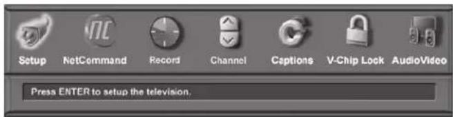
Main Menu: This screen will always be the first screen that appears when you press the remote's TV MENU button.
▶ViewPoint Remote Control Buttons
The following buttons on your remote control help you navigate within the ▶ViewPoint
- ADJUST ◀ or ▶ to select the menu item you want to change.
- ADJUST ▲ or ▼o change the settings.
- ENTER to enter into a menu, start an automatic function or select a check box.
- TV MENU to display the main menu or move back one menu screen at a time.
- CANCEL to clear a setting or stop an automatic function.
- HOME to exit all menus and return to TV viewing.
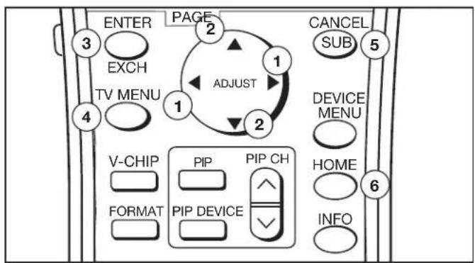
Press ADJUST ▲ or ▼ to change text boxes. Some text boxes have preset labels. Other boxes allow you to select letters, numbers or characters to customize names.
NetCommand® Initial Setup
The initial setup screens that appear when you first power on your new Mitsubishi TV guide you through setup of NetCommand and the TV Guide On Screen® system. Most IR remote control signal formats can be learned by NetCommand.
Welcome Screen
Figure 1
When you first turn on your TV, the NetCommand Welcome screen displays and asks you to select either English or Spanish as the language for the on-screen menus. The default language is English. To change Language later, select Setup in the Main Menu. Selecting Cancel at this screen will cause the default language (English) to be selected.
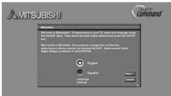
Figure 1. Welcome screen
NetCommand (Information) Screen
Figure 2
The NetCommand (Information) Screen describes how to start or delay the initial NetCommand and TV Guide On Screen setup. This screen displays automatically the first time you power On your new TV, after the Welcome screen.
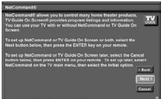
Figure 2. Information screen
Select Next> and press ENTER to start the initial setup.
If the NetCommand Setup is cancelled before it's completed, you can restart the NetCommand setup from the Setup Reminder screen (see below) or by doing the following:
- Press TV MENU on the remote control to display the TV Main menu.
- Select NetCommand. The available options will be Add, Review, Guide or Initial. Change and Delete will be grayed out.
- Press ADJUST ▲▼to select Initial.
- Press ENTER. The Device Setup screen (shown on the next page) displays.
Setup Reminder
Figure 3
This screen only appears if you did not set up NetCommand when the TV was first turned on. The Setup Reminder screen displays for the next six times you power on the TV.
If you would like to set up NetCommand and/or the TV Guide On Screen system, select Next and press ENTER. If you do not wish to set up NetCommand and/or the TV Guide On Screen system, then select Cancel and press ENTER.
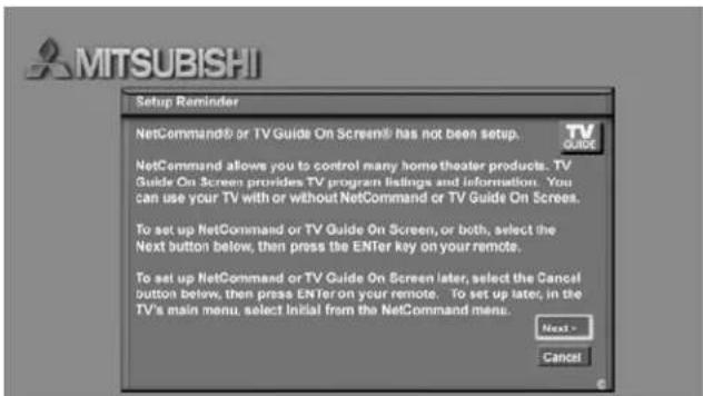
Figure 3. Setup Reminder screen
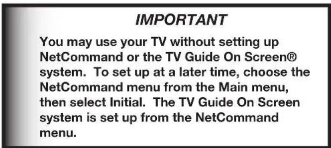
NetCommand® Initial Setup, continued
Device Setup Screen
Figure 4
If the devices connected to the TV are already in NetCommand memory, you can quickly select them at this screen. Press ADJUST or move to each device type. Press ADJUST or to select the manufacturer. Select "Other" if the manufacturer is not listed. Later, you can use the Change setting in the Edit NetCommand menu to learn the remote control signals for this device. Select "None" for device types that are not connected.
For the A/V Receiver, if the manufacturer is not listed, you cannot select "Other". Instead, select "None". Later, you can use the "Add" feature in the NetCommand menu to have the TV add and learn the remote control signals for this device.
If you have a camcorder connected, check the Camcorder box. NetCommand will not be able to control it, but will reserve the front input to use with the camcorder. Check the PC box if you have a PC connected. After completing your choices, select Next> and press ENTER.
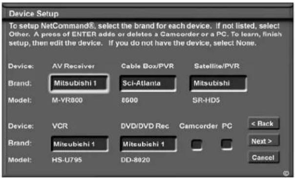
Figure 4. Device Setup screen
Note: If you selected "Other" for any of the device names, you can direct the TV to "Learn" the connected device by following the Edit NetCommand instructions. For many device types, non-listed models will operate in the same way as the listed models and you can still use the pre-loaded setting.
IMPORTANT
NetCommand must be set up and the IR emitters properly placed for your cable box and VCR so the TV Guide On Screen system can control these devices.
TV Guide On Screen® System Setup
Figure 5
The TV Guide On Screen option allows you to select whether you want to enable the TV Guide On Screen system and, if so, which devices you want to include. In order to get the correct listings for your area, you will need to enter your five-digit ZIP code.
You can select one over-the-air source and one cable source for TV Guide On Screen. If, however, you have multiple cable sources, the channel-number assignments may not match up correctly. See the table below for the preferred connection combinations.
| If One Source Is: The Other Source Can Be: | |
| Ant-1 over-the-air reception | Cable box (on any input)Ant-2 channels memorized via cable |
| Ant-2 over-the-air reception | Cable box (on any input)CableCARDTM on Ant-1Ant-1 channels memorized via cable |
For detailed information on using the TV Guide On Screen system, please see the separate TV Guide On Screen Interactive Program Guide User's Manual.
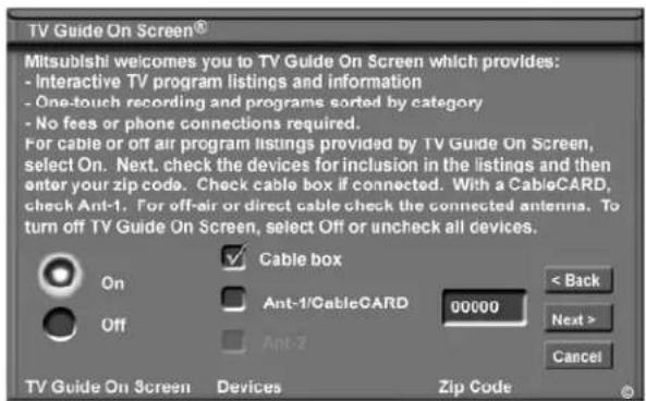
Figure 5. TV Guide On Screen
Note:
- Inputs to TV Guide On Screen can include:
- Only one over-the-air source
- Only one cable source
- If your cable box is connected using HDMI or IEEE-1394, we recommend you also connect an antenna.
- If your cable box is connected to Component 1 or 2, you should make sure the box is set to send analog channels as 480i. If this is not possible, add an antenna.
NetCommand® Initial Setup, continued
Review Screen
Figure 6
After you have made your device choices, the Review Screen will display. It is important to review the settings to ensure that they are correct. If necessary, you can use <Back to return to the Device Setup screen to make changes.
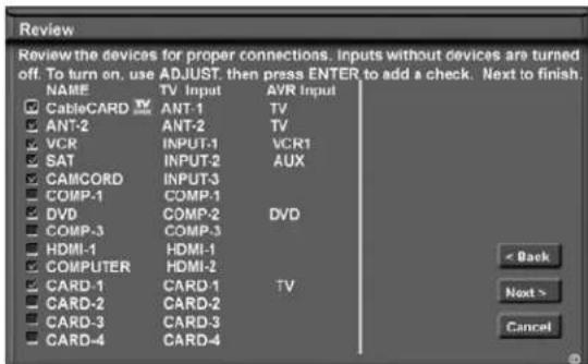
Figure 6. Review screen
Note: The Review screen lists the TV input and A/V receiver input used with each device. You must correctly identify the inputs you used when you connected the devices. If you have not connected your devices, write down these inputs as a guide. If you cannot use these inputs, or if you would like to change the name of a device, use the instructions in Edit NetCommand to make necessary changes.
Note: If you select Next> on the Review screen, all selections made are finalized.
On the Review screen, adding or deleting check marks will turn the adjacent devices or inputs On or Off. 1394 device names only appear on the Review screen when the devices are connected to the TV.
Finish Screen
Figure 7
To complete the NetCommand setup, select Finish from the Finish screen.
If you wish to change any of the pre-configured inputs or names for the devices, or add devices not in the pre-configured setup, select Edit to display Edit NetCommand menu.
If your A/V receiver was not listed, select Edit to add the AVR and then assign all devices to new AVR inputs.
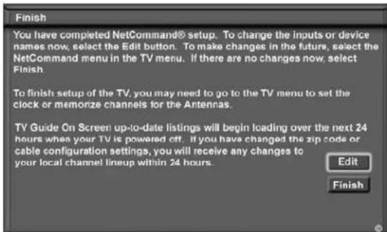
Figure 7. Finish screen
It may still be necessary to memorize the available channels for Antenna-1 (and Antenna-2, if used). You may do that by going to the TV Main menu and selecting Setup. Instructions to memorize channels are found in the Setup menu section.
Edit NetCommand®: Add an A/V Receiver
A/V Receiver Screen
Figure 8
If your A/V Receiver manufacturer was not listed, and you selected "None" during the initial NetCommand setup, you may add the A/V Receiver and have NetCommand learn its remote control's functions. Either select Edit from the Finish screen or, if you have finished the initial setup, go to the Main menu, select NetCommand, then press ENTER. The Edit NetCommand screen will display. Select Add.
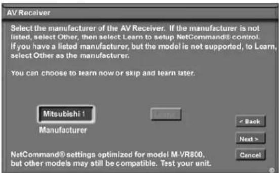
Figure 8. A/V receiver screen
Choose ONE of these options:
- Select a recognized manufacturer. The model number optimized for NetCommand will display at the bottom of the screen. If a number follows the manufacturer's name, (example: Mitsubishi 1), this indicates additional models are optimized for that manufacturer. For many device types, non-listed models will operate in the same way as the listed models and you can still use the pre-loaded setting. After selecting Next>, the screens that follow are: the Name Screen (Figure 12), Audio Output to AVR screen (Figure 13), ending with the Finish screen (Figure 14).
- Select "Other", then highlight "Learn" and press ENTER. This will allow you to have NetCommand learn the remote control signals of this new device. After selecting "Learn" and pressing ENTER, the screens that follow are: the A/V receiver Inputs screen (Figure 9), A/V Receiver Input Learn screen (Figure 10), A/V Receiver Learn screen (Figure 11), Name screen (Figure 12), Audio Output to AVR screen (Figure 13), ending with the Finish screen (Figure 14).
- Select "Other," skip Learn and select Next>. This will allow the device to appear and will allow NetCommand to switch inputs to use this device.
However, NetCommand will not be able to control this device. Later you may use the "Change" option in the NetCommand menu to learn the remote control signals.
After selecting Next>, the screens that follow are: the A/V Receiver Input screen (Figure 8), Name screen (Figure 11), Audio Output to AVR screen (Figure 12), ending with the Finish screen (Figure 13).
A/V Receiver Inputs
Figure 9
If you select "Other" as the manufacturer and then "Learn," you will see the A/V Receiver Input screen. After selecting the number of inputs, this screen will not appear again.
Depending on your A/V Receiver's capability, you may connect up to seven A/V inputs. Select the number of inputs by pressing ADJUST ▲ or .▼
If the number of connected inputs changes, you will need to delete the A/V receiver through Edit NetCommand and add it again, as described above.
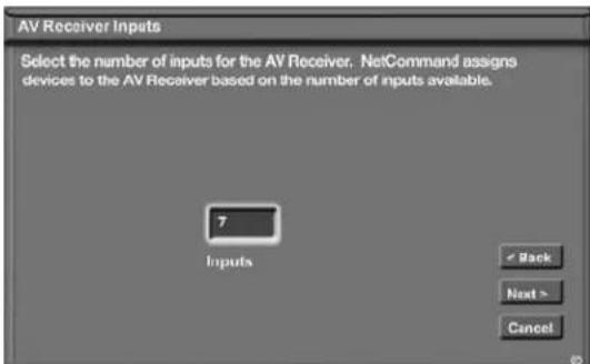
Figure 9. A/V receiver Input screen
Edit NetCommand®: Add an A/V Receiver, continued
A/V Receiver (AVR) Input Learn Screen
Figure 10
NetCommand can now learn the remote control signals used to select each input on the A/V receiver.
- Press ADJUST on the TV remote to select the check box for each function to be learned.
- Press ENTER and the function name will begin to flash to confirm the ready-to-learn status.
- Press the button on the A/V receiver's remote control that corresponds to the selected function. A check mark will appear and the function name will stop flashing. This confirms the signal learned status.
- To test the learned command, press ENTER on the TV remote. The A/V receiver will perform the selected function. The A/V receiver needs to be turned on and the IR emitters properly placed for the test to be successful (see page 32 for IR emitter placement).
- To customize the input names, press ADJUST ▶to move to the Input Name text box and then press ADJUST ▶or ▶and ENTER to select each letter of the name. These names will appear on the Review screen as the A/V receiver's input names, and should match the names the A/V receiver shows in its own display.
- To erase the learned input signal, highlight the check box for that input and press CANCEL.
- Repeat for each connected input.
- When the input selection signals have been learned and the inputs named, press ADJUST ▶to select Next> and move to the A/V receiver Learn screen.
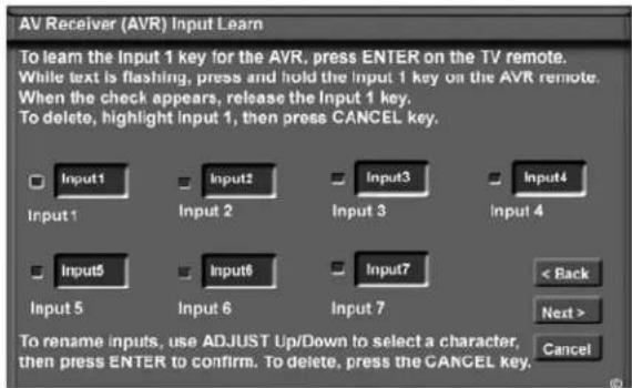
Figure 10. A/V receiver Input Learn screen
A/V Receiver (AVR) Learn Screen
Figure 11
- Press ADJUST ▲ on the TV remote to select the check box for each function to be learned.
- Press ENTER and the function name will begin to flash to confirm the ready-to-learn status.
- Press the button on the A/V receiver's remote control that corresponds to the selected function, A check mark will appear and the function name will stop flashing. This confirms the signal learned status.
- To test the learned command, press ENTER on the TV remote. The A/V receiver will perform the selected function. The A/V receiver needs to be turned on and the IR emitters properly placed for the test to be successful (see page 32 for IR emitter placement).
- Repeat for each function to be learned.
- To erase a learned function, highlight the check box for that function and press CANCEL.
- When the function signals have been learned, press ADJUST ▶ to select Next> and move to the Name screen.
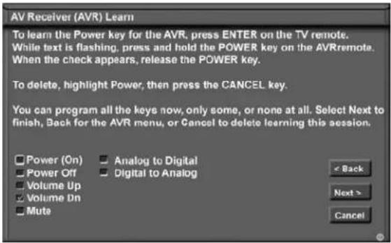
Figure 11. A/V receiver Learn screen
Edit NetCommand®: Add an A/V Receiver, continued
Name Screen
Figure 12
The Name screen allows you to change the default name for the A/V receiver to a custom name of up to eight characters (including a blank space), selecting from letters, numbers, and nine different characters. Using the TV's remote, press ADJUST ▲ or ▶ select each letter, then press ENTER to move to the next position. Press CANCEL to delete the current letter and move back one character position. When in the first position, the CANCEL button will return the name to the default name.
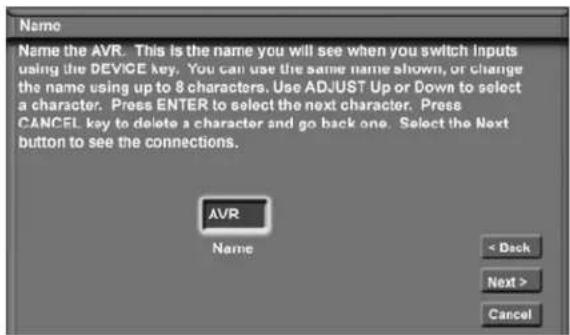
Figure 12. Name screen
Finish Screen
Figure 14
To finalize your selections and complete the A/V receiver setup, select Finish from the Finish screen.
Note: If you connected the audio output of other devices directly to the A/V Receiver, you must use the "Change" function of the Edit NetCommand menu and select each device to assign the correct A/V Receiver input to be used with each device.
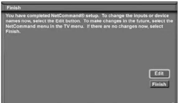
Figure 14. Finish screen
Audio Output to AVR Screen
Figure 13
Use this screen to select which A/V Receiver input is connected to AUDIO OUTPUT on the TV back panel. Press ADJUST ▶to select Next> and move to the Finish screen.
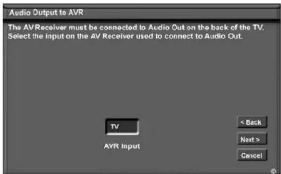
Figure 13. Audio Output to AVR screen
Note: To change any of the inputs or names for the devices, or add devices not included in the initial settings, select Edit to display the Edit NetCommand menu.
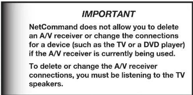
Edit NetCommand®: Add Devices
Mitsubishi's NetCommand allows you to edit your home theater configuration. You can add new devices, change device settings and connections, delete devices and learn remote control IR signals not already in NetCommand memory.
Edit NetCommand Screen
Figure 15
If you selected Edit when you were at the Finish screen, the Edit NetCommand screen displays. Your choices are:
Add:
Add a new device to the NetCommand setup. See Figure 15 for more information.
Change:
Change the brand/model, input connections, or name of a device already listed in the configuration. Learn the remote control signals of devices listed as “Other” brands. See Figure 24 for more information.
Guide:
Edit TV Guide On Screen® ZIP code and input selections. See the separate TV Guide On Screen Interactive Program Guide User's Manual for more information about customizing the Guide.
Review:
View a list of all devices and input connections in the NetCommand home theater configuration, including the A/V receiver. This is also where you can turn On or Off unused TV inputs or devices. See Figure 5 for more information.
Delete:
Remove a device or erase the complete NetCommand home theater configuration. The learned remote control signals are erased when the associated device is deleted. See Figure 25 for more information.
Initial:
Start the setup at the beginning. This button only becomes available after deleting the complete configuration, or if NetCommand was not set up when the TV was first powered On. See Figure 2 for more information.
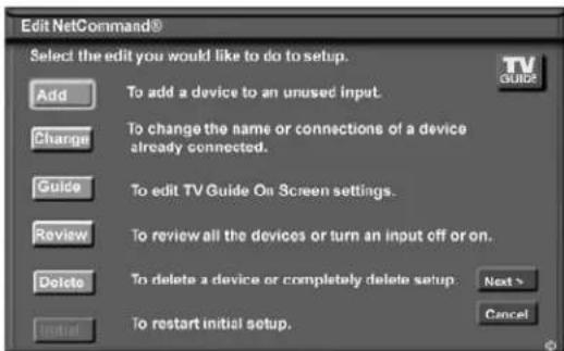
Figure 15. NetCommand Menu, Edit NetCommand Option
Add Screen
Figure 16
Select "Add" from the Edit NetCommand screen, and the New Device screen will display. Select the Device type that you would like to add. You may add your A/V receiver (if not added in Initial setup) Cable Box, Camcorder, SAT (satellite), DVD, Laser Disc, PC and VCR.
At the next screen, choose the manufacturer. If you choose “Other” for the manufacturer, the device (A/V receiver, Cable, SAT, DVD or VCR) can be learned. For device types Laser Disc, Camcorder, Game and PC, the “Learn” screen is skipped. There is no NetCommand support or learning for these devices.
At the next screen, you can keep the default Name or select a custom Name for the device, using ADJUST ▲ or ▼ to select letters A-Z, numbers 0-9, and/or symbols (!.&'/:*- and blank) for each character of the name you would like for the selected channel.
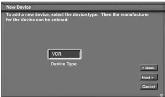
Figure 16. Add screen
Hint: The cable box and satellite receiver learn screens include PVR functions.
Edit NetCommand®: Add Devices, continued
[Device] Screen
Figure 17 If you selected "None", during initial setup, then you can add a device. If you have added a new device, select "Other" as the manufacturer and use this screen to start learning.
Our examples show the choices for adding a VCR, however, the same type of screens will appear for any satellite, DVD player, or Cable Box.
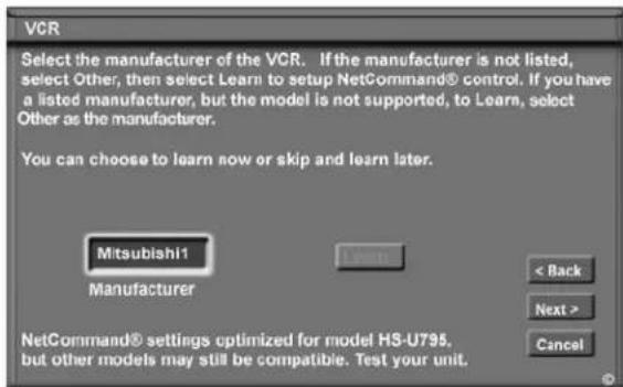
Figure 17. [Device] screen
Choose ONE of these options:
- Select a recognized manufacturer. The model number optimized for NetCommand will display at the bottom of the screen. If a number follows the manufacturer's name, (example: Mitsubishi 1), this indicates additional models are optimized for that manufacturer. For many device types, non-listed models will operate in the same way as the listed models and you can still use the pre-loaded setting.
After selecting Next>, the screens that follow are: the Name Screen (Figure 20), Connection screen (Figure 21) and specialized device screens (Figures 22-24), ending with the Finish screen (Figure 27).
- Select "Other", then highlight "Learn" and press ENTER. This will allow you to have NetCommand learn the remote control signals of this new device.
After selecting "Learn" and pressing ENTER, the screens that follow are: [Device] Learn screen (Figure 18), [Device] Advanced Learn screen (Figure 19), Name screen (Figure 20), Connection screen, (Figure 21) and specialized device screens (Figures 22-24), ending with the Finish screen (Figure 27).
- Select "Other", skip Learn and select Next>. This will allow the device to appear and will allow NetCommand to switch inputs to use this device.
However, NetCommand will not be able to control this device. Later you may use the "Change" option in the Setup menu to learn the remote control signals.
After selecting Next>, the screens that follow are: the Name Screen (Figure 20), Connection screen (Figure 21) and specialized device screens (Figures 22-24), ending with the Finish screen (Figure 27).
[Device] Learn Screen
Figure 18 Shown only if "Learn" was selected
-
Press ADJUST ▲▼to select the check box for each function to be learned.
-
Press ENTER and the function name will begin to flash to confirm the ready-to-learn status.
-
Press the button on the device's remote control that corresponds to the selected function. A check mark will appear and the function name will stop flashing. This confirms the signal learned status.
-
To test the learned command, press the ENTER button on the TV remote while the learned function is still highlighted. The device should perform the selected function. The device needs to be turned on and the IR emitters properly placed for the test to be successful (see page 32 for IR emitter placement).
-
Repeat for each function to be learned.
-
To erase a learned function, highlight the check box for that function and press CANCEL.
-
When the function signals have been learned, press ADJUST ▶ to select Next> and move to the [Device] Advanced Learn screen.
NOTE: When learning the device's remote control signals, point the device's remote control at the TV screen.
Hint: If the device's remote control uses a single button for both Power On and Power Off, don't learn the Power Off function.
Edit NetCommand®: Add Devices, continued
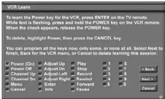
Figure 18. [Device] Learn screen
[Device] Advanced Learn Screen
Figure 19
After learning the basic device keys, the [Device] Advanced Learn screen allows you to learn any special keys for your device. Most common IR remote control signal formats can be learned by NetCommand.
A table of specialized device keys is shown in Appendix E. You only need to learn the functions your devices respond to and can ignore the functions that do not apply to your device.
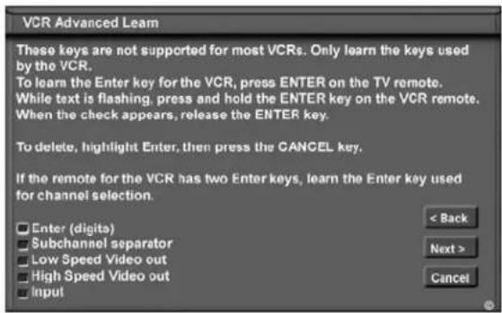
Figure 19. [Device] Advanced Learn screen
Name Screen
Figure 20
The Name screen allows you to change the default name for each device to a custom name of up to eight characters (including a blank space), selecting from letters, numbers and nine different characters. Press ADJUST ▲ or ▼ to select each letter, then press ENTER to move to the next position. Press CANCEL on the remote
to delete the current letter and move back one character position. When in the first position, the CANCEL button will return the name to the default name.
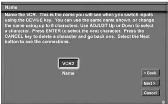
Figure 20. Name screen
Connection for [Device] Screen
Figure 21
Select the TV and A/V receiver inputs that the device is connected to. Connecting only audio to the A/V receiver is recommended. The A/V receiver may need configuring for digital audio.
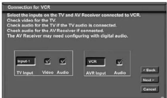
Figure 21. Connection for [Device] screen
Edit NetCommand®: Add Devices, continued
The screens described below may not be necessary for your device setup. If they do not display automatically on screen, they are not required.
VCR for Recordings Screen
Figure 22
Select the VCR to use for making analog recordings through NetCommand or the TV Guide On Screen® system. The VCR inputs must be connected to RECORD OUT on the TV, which outputs analog signals converted from digital.
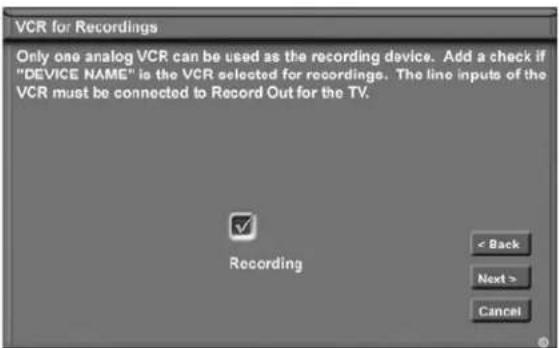
Figure 22. VCR for Recordings screen
RF Connection for Cable Screen
Figure 23
The RF Connection for Cable screen displays only when adding or changing a Cable Box. If your Cable Box is connected to a TV Antenna input, check the RF check box. Select the TV antenna input that is used with the Cable Box. Select the channel number used for output by your cable box from the choices listed (003, 004, 005). If the Cable Box is also connected to a VCR for recording, select that VCR.
If your Cable box is connected using Audio/Video or component cables, make sure the RF check box is unchecked. Then the next screen will be Connection (Figure 20), to allow the selection of the TV input used with the Cable Box.
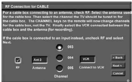
Figure 23. RF Connection for Cable screen
Chapter 3. NetCommand Setup and Editing
IR Code for [Device] Screen
Figure 24
This screen only displays if an added device has the same IR code as a previously added device of the same type and manufacturer. You can specify the IR setting for the new device. For example, for the second Mitsubishi VCR you can specify the IR Code setting to VCR-B, if the primary Mitsubishi VCR is using the VCR-A IR code.
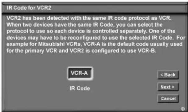
Figure 24. IR Code for [Device] screen
Edit NetCommand®: Change or Delete Devices
Change Device Screen
Figure 25
Selecting Change from the Setup menu screen, displays the Change screen. To change a device, select the device by name, not type. You can change the name or input connections to the TV and A/V receiver. If "Other" was selected for the manufacturer then you can also "Learn". The rest of the screens that follow are the same as when you Add a device.
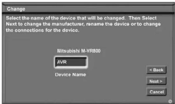
Figure 25. Change screen
Delete Device Screen
Figure 26
Selecting Delete from the Setup menu, displays the Delete screen. You can choose to delete a single device by selecting the device you would like to delete, or you can delete the entire NetCommand configuration. After you have chosen the device, or the entire configuration, you will be prompted to confirm your choice to delete. If you select the Entire Configuration, the Initial button becomes available on the Edit NetCommand screen. If you delete a device that you learned the remote control signals for the learned signals are erased.
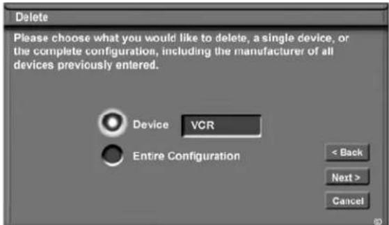
Figure 26. Delete screen
Finish Screen
Figure 27
To finalize your selections and complete the NetCommand setup, select Finish from the Finish screen.
Note: To change any of the inputs or names for the devices, or add devices not included in the initial settings, select Edit to display the Edit NetCommand menu.

Figure 27. Finish screen
IMPORTANT
NetCommand does not allow you to delete a device or change the connections for a device (like a VCR or a DVD player) if the device (input) is currently being displayed by the TV.
Switch the TV to a different device from the one you are changing or deleting. To change the A/V receiver, you need to be listening to the TV speakers.
IMPORTANT
NetCommand must be set up and the IR emitters properly placed for your cable box and VCR so the TV Guide On Screen system can control these devices.
Chapter ...

IEEE 1394 Devices and NetCommand®-Controlled Recordings
IEEE 1394 Devices and NetCommand® Control....54
Adding IEEE 1394 Devices Automatically. 55
Device Selection Menu 57
Using the Device Menu Button to Display Menus ....58
Using the GUIDE Button to Display ChannelView™ and Menus ... 59
NetCommand®-Controlled Recordings
IEEE 1394 Devices and NetCommand® Control
See pages 30-31 for information regarding compatible IEEE 1394 devices and connection styles. The TV is not able to control IEEE 1394 devices that use other types of control protocols. Incompatible digital audio, video and/or control information will still be able to pass from one device through the TV to another device on the network. These incompatible devices may not appear on the Device Selection menu or in the Review screen of the Edit NetCommand menu.
NetCommand Control of Digital Devices Using the "Learn" Feature.
Some IEEE 1394 devices such as cable boxes or satellite receivers will not have compatible digital control signals or require the use of the device's own remote control. Some of these IEEE 1394 devices will not display on-screen information through the IEEE 1394 connection and will require using an analog connection for on-screen displays. In many cases, to control these digital devices, the Learning feature of NetCommand can be used.
- Place an IR Emitter for NetCommand in front of the device's remote control sensor (see IR Emitters, page 32).
- On the Name for 1394 Device screen (Figure 2, page 55) use ADJUST and ENTER to check mark the Analog Connection box.
- Select the device type on the IEEE 1394 Device Type screen (Figure 3, page 56) of SAT or similar tuning device
- If desired, using the ADJUST buttons enter a custom Name on the Name screen (Figure 20, page 50).
- At the Device screen, Select "Other" as a manufacturer and then highlight "Learn" and press Next (Figure 4, page 43).
- Follow the device learning instructions found on the screen(s) or in the Edit NetCommand section of Chapter 3.
- The Connection screen (Figure 5, page 56) follows the learning screens. If analog connections are used, select the correct inputs. If only digital connections are used, do not check the video or audio boxes.
- Proceed with the Finish screen.
This will allow NetCommand to use the learned remote control signal to control these IEEE 1394 devices.
Note: When using the NetCommand learning feature for IEEE 1394 devices that do not have analog connections, the GUIDE function will require pressing GUIDE twice. The first press of GUIDE will display the TV's digital channel guide. The second press will display the program guide for the device if an IEEE 1394 Guide is available.
Adding IEEE 1394 Devices Automatically
Adding IEEE 1394 Devices Automatically
When an IEEE 1394 device is connected into the TV network and is powered On, the new device will automatically announce its presence. This process is called device discovery and can take up to 1 minute. Some non-audio/video or non-compatible IEEE 1394 devices, such as Personal Computers (PCs), may not announce their presence to the TV. The TV will not be able to show these devices in the Device Selection menu, however, they can coexist and will still be available to other devices on the IEEE 1394 network that are compatible with these non-audio/video devices.
IEEE 1394 cable boxes and satellite receivers may require that you use the remote control that came with those devices. For some compatible devices, the Cable/SAT/DTV position of the TV remote control may be able to control operation.
New 1394 Device Screen
Figure 1 When your TV discovers a new IEEE 1394 device, the New 1394 Device screen will appear. Selecting “Add” will include the device in the Device Selection menu. Selecting “Do Not Add” will not add the device to the Device Selection menu. If the IEEE 1394 device does not provide audio and video, you may not want to add that device to the TV’s Device Selection menu. Devices that were discovered but not added to the Device Selection menu will still be listed in the Review screen of the Edit NetCommand® menu.
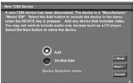
Figure 1. New 1394 Device screen
Name for 1394 Device Screen
Figure 2 If you choose to add the discovered IEEE 1394 device, the Name for 1394 Device screen will appear. Name the device or use the default name that appears automatically.
Some IEEE 1394 digital devices, such as some DVCRs, can also operate as analog devices. For example, some DVCRs can record and play as VHS or S-VHS, in addition to D-VHS. This allows you to play analog rental tapes or analog tapes from your established library or make analog recordings from antenna or cable systems. To use the analog capability, check the Analog Connection box.
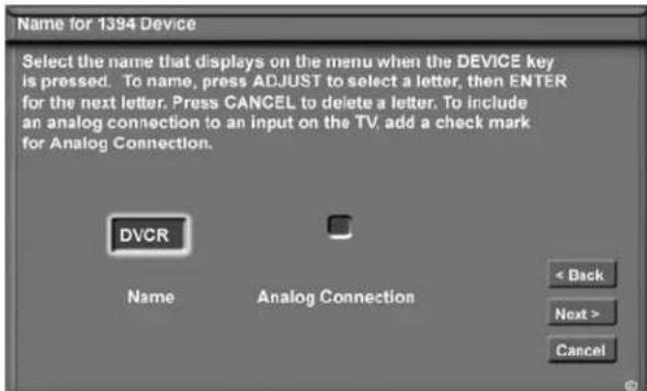
Figure 2. Name for 1394 Device screen
Adding IEEE 1394 Devices Automatically, continued
IEEE 1394 Device Type Screen
Figures 3 and 4
If the new IEEE 1394 device is also connected using analog inputs, you will need to define the device type. Select the type of device, such as a VCR.
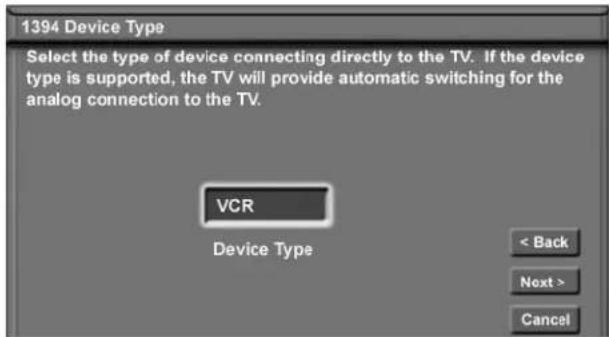
Figure 3. IEEE 1394 Device Type screen
Once the device type is selected, then the Device screen is displayed so the manufacturer can be selected. If the manufacturer is listed, then you may be able to control this device while it is operating as an analog VCR. For example, if the IEEE 1394 device you have added is a Mitsubishi DVCR, and you have selected an analog connection as a second connection, then you will select Mitsubishi for the manufacturer. If the manufacturer is not listed, select "Other" and use the Learn screens
Be sure to place an IR Emitter in front of the remote control sensor, just as you have done for other NetCommand® devices. It is necessary to use the IR Emitter only when the DVCR is being used as an S-VHS or VHS VCR. When the DVCR is playing or recording digital signals in D-VHS, the TV will control the VCR through the IEEE 1394 cable.
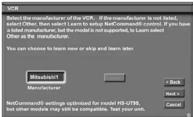
Figure 4. Device screen
Connection Screen
Figure 5
Select the TV input that you used when you connected the video or S-Video cables. You may also select the TV or A/V receiver input you used when you connected the stereo audio cables.
The playback and record control of some DV camcorders may still operate by the IEEE 1394 cable automatically, even though you must use the video or S-video cable for the picture. In this case, when you select the Camcorder, be sure to select analog (not digital) from the pop up when a camcorder is selected from the Device Selection menu. Then the picture is shown via the analog connection but control is from IEEE 1394.
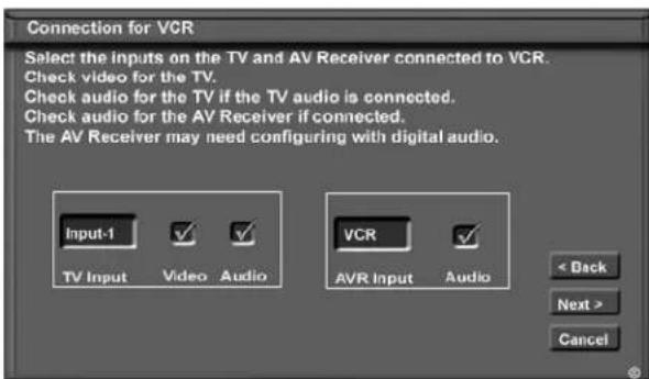
Figure 5. Connection screen
Finish Screen
Figure 6
To finalize your selections and complete the NetCommand setup, select Finish from the Finish screen.
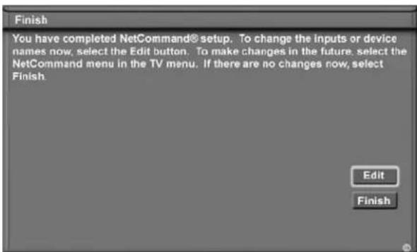
Figure 6. Finish screen
Device Selection Menu
When you press DEVICE on the TV's remote control, the Device Selection menu (Figure 7) displays. If NetCommand® has not been set up, the Device Selection menu allows you to select an input for viewing. If NetCommand is set up, the Device Selection menu allows you to select the device for viewing, select audio from the TV speakers or A/V receiver, power compatible devices On or Off, and verify the destination of signals. On the Device Selection menu, the device or input currently displayed appears as a gold-colored icon.
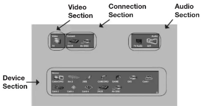
Figure 7. Device Selection Menu with NetCommand
Power On/Off Devices
Devices that have separate On and Off remote control buttons will power On automatically when you select the device and will power Off when you turn off the TV. For devices that do not power On or Off automatically, display the Device Selection menu, press ADJUST ◀ or ▶ to highlight the device icon and press POWER on the remote control. For the A/V receiver, press AUDIO to move the navigation to the Audio Section. Highlight the A/V receiver icon and press POWER. If you press POWER on the remote control when the Device Selection menu is not displayed, the TV will turn Off.
Device Section
To select another device or input, press ADJUST
▲▼◀ on the TV's remote to move the highlight.
Press ENTER to select the device to view and hear. The TV inputs are automatically changed. If NetCommand is set up, the inputs on compatible A/V receivers are automatically changed at the same time.
Video Section
The destination of the device highlighted in the Device Section is displayed here as a TV icon.
Connection Section
The Connection Section shows the recording in progress and the device that is recording from the source. For example, if the Digital VCR (D-VCR) is currently recording, when you move the highlight to the Ant-1 icon, the D-VCR icon will appear in the Connection Section. This icon will disappear when you move the highlight to another icon, press CANCEL to stop recording.
Audio Section
When a NetCommand pre-memorized or learned IR controlled A/V receiver has been connected to the TV and added to NetCommand Setup, an AVR icon will appear in the audio section. Press AUDIO to change navigation to the audio section. Then press ADJUST
▲▼◀to select the TV speakers icon or the A/V receiver icon. Press ENTER to change the audio selection. Press DEVICE to return the navigation to the Device Section.
PIP Device Selection Menu
Figure 8
The PIP Selection menu displays when you press the PIP DEVICE button on the remote control. This menu has the same general format as the Device Selection menu. The source for the Video Section is the sub picture and the Audio and Connection Sections are not available.
Use ADJUST ▲▼→move the highlight to the device to show in the PIP screen, then press ENTER. Device icons that are grayed out are not available for use as PIP sources or with the current source.
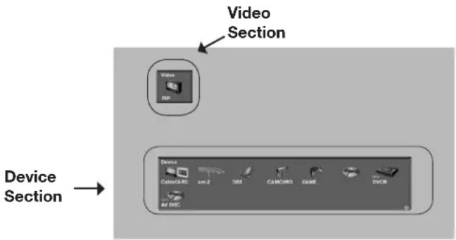
Figure 8. PIP Device Selection Menu
IMPORTANT
If a device does not respond to separate On or Off remote control signals, the manufacturer has not provided that ability for the device.
Using the Device Menu Button to Display Menus
Device Menu
If the input is a VCR or DVD, and NetCommand is set up, the first press of DEVICE MENU displays the transport menu of the current device. Another press of the DEVICE MENU button will display menu for the current device source, if available.

Figure 9. Transport menu
When used with the TV Guide On Screen, DEVICE MENU displays or removes TV Guide's menu information. See the TV Guide On Screen Interactive Program Guide User's Manual for detailed information.
IR Controlled Devices
For a NetCommand compatible traditional IR controlled device, pressing DEVICE MENU once or twice will display the menu for that device. While the menu for the device is displayed, press ADJUST
▲▼◀ and ENTER to navigate the screen. For some NetCommand traditional devices you will also be able to use the number buttons and other additional buttons on the TV remote. For traditional DVD players, DEVICE MENU is also known as the setup menu.
then press ENTER to access the linked page. Pressing DEVICE MENU will return to the CableCARD menu screen and pressing HOME will return to TV viewing. The screen shown is an example of the type of screen that may display. Specific screen menus are sent by your cable provider.
If there are technical problems with the CableCARD, an error screen will automatically display with information that may be needed by your Cable provider when you call them for assistance.
Moving Through Other CableCARD Screens
In addition to CableCARD menus, other CableCARD application screens may display and require you to make additional selections. While CableCARD application screens are customized in each area, some general rules apply in using these screens on your Mitsubishi television.
- Blue text denotes a link to another screen. Press ENTER to move to the next application. When screens do not have blue text, there are no more links.
- You cannot move backward through the links. If you want to exit the CableCARD system, press HOME to exit and return to TV viewing. CANCEL may not work with some CableCARD screens.
All information on these application screens is provided by your local cable company. Please contact your cable provider if you have any problems with the application screen displays.
CableCARD™ Menu
Figure 10
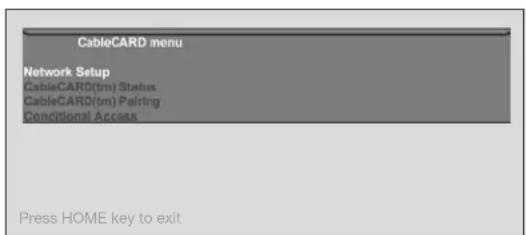
Figure 10. Possible Device Menu for CableCARD
When using a CableCARD, pressing DEVICE MENU will display a list of up to 8 links to applications that contain basic CableCARD information made available from your cable provider. Press ADJUST ▲ or ▼ move through the application links. To select a link (blue text) to an application, press ADJUST ▲ or ▼ highlight the link,
IMPORTANT
Most CableCARD screens are status or diagnostic in nature and do not allow you to make changes. These screens are meaningful only to your local cable provider.
Using the GUIDE Button to Display ChannelView™ and Menus
The GUIDE Button
Please refer to the separate TV Guide On Screen® User's Guide for details about using the GUIDE button with TV Guide On Screen. When you are not using the GUIDE for the TV Guide screens, pressing GUIDE allows you to see NetCommand® controlled program guides or menus.
GUIDE and Devices (1394 or IR Controlled)
For NetCommand compatible satellite receivers and some cable boxes, GUIDE will display the on-screen programming guide for the receiver or cable box. Press ADJUST ▲▼◀n# ENTER to navigate the displayed Guide. For NetCommand compatible satellite receivers, you may also be able to use the number or other additional buttons.
For NetCommand compatible DVD players, GUIDE will display the DVD disc "top" menu (not the setup menu). For A/V Discs, pressing GUIDE will display the Track List screen For IEEE 1394 devices with digital connections, press GUIDE twice to display the device's Guide. For media cards, pressing GUIDE displays a JPEG thumbnail menu (video) or a Play list menu (audio).
GUIDE and the Device Selection Menu
For compatible traditional VCRs, pressing GUIDE when the VCR is highlighted on the Device Selection menu will change the VCR's input.
When the A/V Receiver icon is highlighted in the Audio Section, pressing GUIDE switches the A/V Receiver from analog audio to digital audio and vice versa, if supported.
GUIDE and the Record To Menu
When in the Record To menu, pressing GUIDE will display the current list of programmed recordings. Please see Record List, page 57 for more information.
GUIDE and ChannelView
Figures 11 and 12
ChannelView is available for antenna inputs not associated with TV Guide. Press GUIDE while viewing ANT-1 or ANT-2 to display a list of available memorized digital channels (D) and analog (A) channel information (if available from the broadcaster). This list is called ChannelView™
ChannelView for digital channels will show the major and sub-channels (or bitstreams). Analog channel information will display as sent. Press ADJUST ▲ or ▼ to scan through the all the channels in memory one by one. To cycle through the choices quickly, press CH ▲ or ▼
For detailed program information, press ADJUST ▶, to return to basic information press ADJUST ◀This information is sent by the broadcaster. If limited data is shown or no program data appears, it is because the broadcaster is not sending the information. This is not a defect of your TV.
Recording a Current Program
To record a current program, press REC (record) when your program choice is highlighted on the program list in ChannelView. A red "R" will be added after the input name. The TV will immediately switch to the selected channel and start recording.
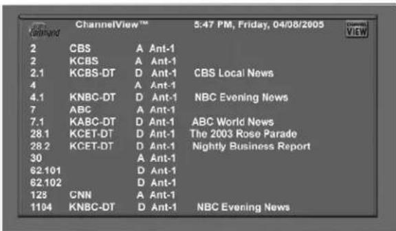
Figure 11. ChannelView screen, current programs
Recording Future Programs
To record a future program, press ADJUST ▲ or to select the channel you want to record from. For detailed program information, press ADJUST ▶ to return to basic information press ADJUST ▼ Press REC (record) when your choice is highlighted. A red "R" will be added after the input name. The message, The recording has been added to the Record List will display. To view, change or cancel a recording, use the Record List (page 57).
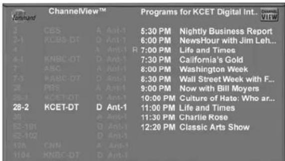
Figure 12. ChannelView screen, future programs
IMPORTANT
Figure 11 For complete ChannelView information to be refreshed daily, the TV must be powered Off from 5 to 15 minutes a day, depending on the number of channels in memory. If the TV loses power, the program listings will be temporarily lost.
NetCommand®-Controlled Recordings
Setting up Recordings
Figure 13
Through NetCommand, you can automatically start and stop recordings and send signals from one playback device to a recording device. Recordings can be made on recordable devices connected to the TV.
The TV can convert digital channels and IEEE 1394 device signals to analog signals that can be recorded on NetCommand compatible analog VHS and S-VHS VCRs
You can schedule the recording to take place at a later time and program the recording duration for a minimum of 30 minutes and a maximum of 6 hours (in 30 minute increments). The default is 1 hour. During the recording, the TV can be powered Off. If the TV is powered On, it will be tuned to the source that is being recorded. The TV should remain on this source to ensure the recording continue without interruption.
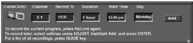
Figure 13. Record to screen
Recording Now
Can be used when viewing Antenna 1 or 2, an IEEE 1394 device, or a non-recording traditional device.
To initiate recording now:
- Press REC (record) on the TV remote.
- In the "Record to" section, review the destination device and duration. Use ADJUST ▲ or ▶ change, if necessary.
- Press a second time and the recording will start.
Time-Delayed Recording
- Press REC (record) on the TV remote.
- Press ADJUST ▶r ▶ to select the Record to device, duration time, start time (press ENTER after selecting hour, minutes and AM or PM to set the time) and day, using ADJUST ▶or ▶to change,. For devices that can select channels, select the channel.
- Select Add and press ENTER to add the recording to the record list. If your selection is successful, a confirmation message will be displayed. If you pick overlapping times, day(s), or destination devices, you will see a message stating there is a conflict.
- To exit, press HOME on the TV remote after all recordings have been added.
Record List, Peer-to-Peer Connections
Record List
Figure 14
Press GUIDE while viewing the Record To screen to see a list of all currently programmed recordings. A maximum of 32 recordings can be scheduled.
To cancel a recording on the Record List, press ADJUST▲ or ▼ to select the recording, then press CANCEL. To page through the list, press CH ▲ or ▼
| Record List | ||||
| The list of recordings for the next week. To cancel a recording, select the recording with the ADJUST keys, then press the CANCEL key. Press the MENU key to return to the Record screen. | ||||
| Day | Start | Duration | Device | Record to |
| Monday | 8:00 pm | 1 hour | Ant-1 5-1 | VCR |
| Tuesday | 8:00 pm | 1 hour | Ant-1 2 | VCR |
| Every Wed | 8:00 pm | 30 min | Ant-1 2 | VCR |
| Wed. | 9:00 pm | 1 hour | Ant-1 4 | VCR |
| Thursday | 8:00 pm | 1 hour | DSS | VCR |
| Thursday | 9:00 pm | 1 hour | Ant-1 7 | DVCR |
| Friday | 8:00 pm | 30 min | Ant-1 2 | AV Disc |
| Every Sat | 11:30 pm | 1 hr 30 min | Ant-1 4-1 | VCR |
Figure 14. Record List screen
TV Guide On Screen® and the Record List
Programs scheduled through TV Guide On Screen will not appear on this record list. Refer to the separate TV Guide On Screen® User's Guide for information regarding Recording and Schedules with TV Guide On Screen.
If there is a conflict between recordings scheduled through TV Guide On Screen and the Record List, the TV Guide On Screen recording will be used.
Cancel Current Recordings
To cancel a recording in progress, press DEVICE to display the Device Selection menu and highlight the source of the recording. Confirm that the icon for VCR (or recording device) is in the Connection Section next to the TV icon. Press the CANCEL button. The icon for the VCR (or recording device) will disappear from the Connection Section to confirm the cancellation.
Peer-to-Peer Connections
A peer-to-peer connection allows the IEEE 1394 devices in your TV network to talk to each other without the further need of TV intervention once the peer-to-peer connection is established. For example, the TV can setup a connection for an A/V Disc or DVCR that sends a recorded program to an IEEE 1394 monitor in another room. NetCommand will establish the connection between the two devices. Once the connection has been established, the TV can be turned off or used to watch another device. Recording from digital channels to a DVCR is also a peer-to-peer connection. In this case, the TV is one of the devices in the peer-to-peer connection.
NOTE: Multiple peer-to-peer connections can occur simultaneously, sometimes with the same source device
Setting up a Peer-to-Peer Connection
A peer-to-peer connection is a current connection and cannot be setup as a delayed connection.
To establish a peer-to-peer connection:
- Tune to source.
- Press CONNECT or REC/CONNECT on the TV remote.
- In the "Record to" section, review the destination device (example: DVCR) and duration. Change if necessary.
- Press CONNECT or REC/CONNECT a second time to initiate recording.
NOTE: Multiple peer-to-peer connections can occur simultaneously, sometimes with the same source device. Also, please note that peer-to-peer connections are NOT listed on the Record List screen.
Canceling a Peer-to-Peer Connection
After a peer-to-peer connection has been established, you can cancel it by highlighting the source device in the Device Selection menu. Confirm that the on-screen icon for the peer-to-peer connection is in the Connection Section next to the TV icon, then press CANCEL. The connection will end and the destination icon will be removed. If there is more than one peer-to-peer connection for the same device, all of the connections will all be canceled.
Using A/V Discs Direct VCR Recording from an Antenna or Cable Source Copy-Protected Material and Restrictions for Traditional VCRs
Using A/V Discs
A/V Disc Search
NetCommand is able to search to a specific time in a recording on an IEEE 1394 A/V Disc.
- Start the desired track's playback on the A/V disc.
- Use the number buttons to enter the time code position of hours followed by minutes. For example, to enter one hour and twenty-two minutes (1:22) into the track, enter 1, 2, 2.
- Press ENTER to skip to the time code position.
- To cancel the request or to start over, press CANCEL instead of ENTER.
Track List Screen
Figure 15 When viewing an A/V Disc, press GUIDE to display its Track List. The time and date it was added, the duration and title will be displayed. Tracks will be listed in date and time order and will vary in size. Press ADJUST ▲ or ▼ navigate through the Track List. To play a track, select it on the list, then press ENTER. To change pages, press CH ▲ or ▼ To delete a track, select it on the list and press CANCEL.
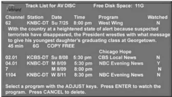
Figure 15. Track List screen
Using the Remote Control with an A/V Disc after selecting from the Device Selection menu:
GUIDE: displays the Track List of recorded programs.
PLAY: resumes playback of paused program.
PAUSE: pauses or resumes playback of program.
FF/FWD: forward picture search, multiple presses increase the speed.
REW/REV: reverse picture search, multiple presses increase the speed.
ADJUST← skip backward 12 seconds per press.
ADJUST▶: skip forward 30 seconds per press.
ADJUST▲: skip to the end of the track.
ADJUST▼: skip to the beginning of the track.
REC: Display the Record Menu to schedule recordings
Direct VCR Recording from an Antenna or Cable Source:
When your VCR is the recording device, pressing REC (record) on the TV's remote control will function the same way as pressing the record button on the VCR's remote control or front panel.
To record directly from antenna or cable:
- Press DEVICE on the TV's remote to display the Device Selection menu. Highlight the traditional VCR and press POWER to turn on the VCR. If necessary, press GUIDE to select the input the VCR is on, such as Antenna input (or line input).
- Press ENTER to switch the TV to the VCR.
- Select the correct channel for recording on the VCR and then press REC to start recording. You will need to manually stop the recording at the end of the program
OR...
With the VCR as the selected recording device, press the DEVICE MENU button to display the VCR's menu, in which you can schedule a delayed recording directly from antenna or cable.
To record from ANT-1, ANT-2 or other devices, see NetCommand Controlled Recordings or refer to the TV Guide On Screen® User's Guide.
Copy-Protected Material
When attempting to record copy-protected material, the Record functions of the NetCommand and IEEE 1394 systems may be prevented or stopped. If you have a recording that is tagged "Record Once", NetCommand will change the tag to "Record No More."
Restrictions for Traditional VCRs
- Your VCR should be connected directly to the RECORD/OUT and VIDEO outputs.
- The VCR must be set manually to "Line Input." Display the Device Selection menu, highlight the VCR and press GUIDE to change VCR inputs.
- If NetCommand is set up, the TV can select channels on compatible cable boxes for recordings. Leave the cable box turned on.
- If the source device or recording device does not have separate power On and Off features, then leave that device powered On.
- You cannot record from source devices connected to the TV Component 1–3 or HDMI 1 or 2 connections.
Chapter ...

TV Menu Screen Operations
Main Menu....64
Setup Menu 65
NetCommand® Menu 67
Record Menu 68
Channel Menu 70
Captions Menu....72
V-Chip Lock Menu 74
Audio/Video Menu 77
A/V Setting Descriptions: Audio 78
A/V Setting Descriptions: Video. 79
Main Menu
Setup Menu
Figure 1
Use the Setup menu to select English or Spanish as the language for the menus and on-screen displays. Memorize the available channels for antennas or cable connected to the ANT-1 and ANT-2 inputs. Manually set the time for the TV, or select Auto and the TV will automatically set the time based upon Extended Data Service (XDS) time data. This time data is usually broadcast by your local PBS station. This menu is also used to set the TV timer, and reset the lamp reminder. The TV's software version is displayed on this screen.
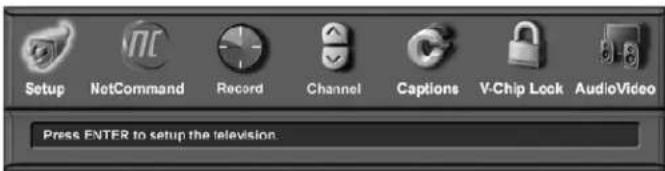
Figure 1. Main menu, Setup selected
NetCommand Menu
Figure 2
Add, change, review or delete NetCommand® settings and devices. Change TV Guide On Screen ZIP code and input selection settings. Change the order of icons on the Device Selection menu. Turn the transport menu off.

Figure 2. Main menu, NetCommand selected
Record Menu
Figure 3
Set up and view recordings and recording defaults. View your customized Record List. If you have more than one digital recording device connected, use this menu to change the default digital Record To device. Set analog recording size and quality.

Figure 3. Main menu, Record selected
Channel Menu
Figure 4
Edit channels for ANT-1 and ANT-2. After memorization, if a channel displays as digital and analog, you can choose to see the channel digitally every time it is selected. Manually add or delete channels from memory, name channels or add your favorite channels to a SQV (SuperQuickView™) list. Displays signal strength of currently tuned digital channels.

Figure 4. Main menu, Channel selected
Captions Menu
Figure 5
Display Closed Captions if sent by the broadcaster, select settings for analog or digital captions.

Figure 5. Main menu, Captions selected
V-Chip Lock Menu
Figure 6
Block or allow programing based upon rating signals sent by the broadcast station, lock by time, or lock the front panel buttons.

Figure 6. Main menu, V-Chip Lock selected
Audio/Video Menu
Figure 7
Reset the A/V Memory to return to the original factory A/V settings for a selected device. Customize the individual audio and video settings. Display a blue screen when viewing a device with no signal, enhance the darker parts of bright pictures or turn the TV speakers On or Off.

Figure 7. Main menu, Audio/Video selected
Setup Menu
Setup Menu
Figure 8
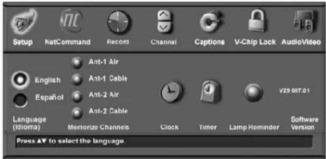
Figure 8. Setup Menu, Language Option
Language
Display the on-screen menus in either English or Spanish (Español). The first time you powered On your TV, you were requested to select an on-screen menu language. If you choose to change the selection, all menu text will immediately switch to the language of your choice. To listen to audio in other languages (when available), see the section of this Owner's Guide covering audio settings.
Memorize Channels
For Antenna 1 (Main) or Antenna 2 (Aux)
To start channel memorization, first select an input according to the table below.
| Input Condition | |
| Ant-1 Air | When connected to an indoor/outdoor antenna |
| Ant-2 Air | |
| Ant-1 Cable | When connected to direct cable |
| Ant-2 Cable |
Press ENTER to start the automatic channel-memorization process. The memorization process is started separately for each antenna selection.
During the memorization process, all possible channels on the selected antenna are scanned twice. Analog channels are scanned first and then the process is repeated for digital channels.
To stop the automatic channel-memorization process before the process is completed, press CANCEL. Channels memorized before you pressed CANCEL are retained in memory. If you start the memorization process again, all previously memorized channels for the selected antenna input are erased and the process starts over from the beginning.
After memorizing channels, the channels in memory can be accessed in ascending or descending order by pressing CH ▲ or . ▼Select the Channel Menu to access further channel-editing features such as channel add or delete, channel name, and SQV custom favorite channel memories.
When you use a CableCARD™, the complete list of available channels is provided through the CableCARD. As a result, the Ant-1 channel-memorization options are not available and are shown grayed out on the screen.
In the TV Guide On Screen® system, the channels displayed and the order in which they are displayed in the Guide is independent of the channel-memorization process. Refer to the TV Guide On Screen Interactive Program Guide User's Manual for detailed instructions on editing channels shown in this guide.
Clock
You may choose to manually or automatically set the clock that your TV will use for recording or timer functions.
Manual
Figure 9
To manually set the clock, you need to select the current time, current date, time zone for your area and the Daylight Savings time setting.
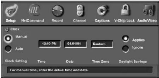
Figure 9. Time Menu, Manual Clock Setting
Time
Press ADJUST ▲ or ▼peatedly to slowly select the hour or press and hold to quickly select the hour. Press ENTER to move to the minutes options. Press ADJUST ▲ or ▼to select minutes.
Setup Menu, continued
Date
Press ADJUST ▲ or ▼ to select the correct date.
Time Zone
Select your correct time zone. Press ADJUST ▲ or to select the time zone (Atlantic, Eastern, Central, Mountain, Pacific, Alaska or Hawaii) for your area. Then press ADJUST ▶ to move to the Daylight Savings time option.
Daylight Savings Time
Select the Daylight Savings time (DST) option that your state uses. Press ADJUST ▲ or to select Applies if your state or area uses DST, or Ignore if DST does not apply.
Auto
Select the Time Zone and Daylight Savings time setting, as noted above. You may then tune to a channel (on ANT-1 or ANT-2) that uses Extended Data Service (XDS) time data, typically a PBS channel. The Auto selection will automatically retrieve the correct time and date information from this channel. Be aware that if a channel displays incorrect time information, it is because of information sent from the broadcaster and is not a defect of the TV.
Timer On/Off
Figure 10
The timer allows you to set up a time when the TV will change the channel and turn on the TV On. You will need to select the time and day to turn the TV On and the device and channel to display. At your preselected time, the timer will turn the TV On, and this message will be displayed: "Press a button for the TV to stay on". Press any button on the remote control within 5 minutes or the TV will turn itself Off.
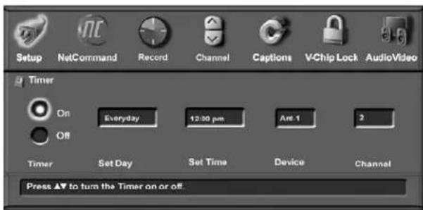
Figure 10. Timer Menu (Timer On/Off)
Set Day
Select the day or days that the TV will turn on automatically. Press ADJUST ▲ or ▶ select Daily, Mon-Fri (Monday through Friday), or the individual days of the week.
Set Time
Press ADJUST repeatedly to slowly select the hour or press and hold to quickly select the hour. Press ENTER to move to the minutes options. Press ADJUST ▲ or ▶ to select minutes.
Device
Press ADJUST ▲ or to select the device to use when the timer turns on the TV. If the TV is already on, the timer will turn the TV to this selected device.
Channel
When an antenna is the selected device, you may select any memorized channel. Press ADJUST ▲ or t▼ select the channel and the TV will tune to this channel in memory when the timer turns it on. This includes sub-channels for digital choices.
Lamp Reminder
Select to reset the lamp reminder message after you have changed the lamp cartridge. Press ENTER to reset the lamp reminder. To have an accurate reminder that the lamp cartridge may soon need replacement, reset the lamp reminder only when you replace the lamp cartridge. See Appendix H for detailed information about changing the lamp.
Software Version
For some service related issues, it may be necessary to know which software version is in your TV. This information is displayed on the Setup menu screen.
NetCommand® Menu
NetCommand Menu
Figure 11
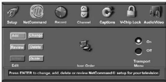
Figure 11. NetCommand Menu
Edit
Detailed information regarding setting up and editing the NetCommand menu is found in Chapter 3. The Edit NetCommand screens allow you to add new devices and change traditional and IEEE 1394 devices. You can also set up the TV Guide On Screen® system or turn it on or off. Turn devices and unused inputs On or Off, delete a single device or delete the entire setup configuration. If you choose to delete the entire configuration, or if the NetCommand setup was cancelled, deleted or not completed, you can start at the Initial NetCommand screen. The Review screen shows all devices connected to the TV.
Icon Order
Figure 12
The Icon Order screen allows you to arrange the device icon order on the Device Selection menu to a different sequence, for ease of selection and operation.
To change the order, press ADJUST ▲, ▼, ◄▶ highlight the icon to be moved and then press ENTER. Press ADJUST ▲, ▼, ◄▶ move the icon to the desired position and then press ENTER to select the icon.
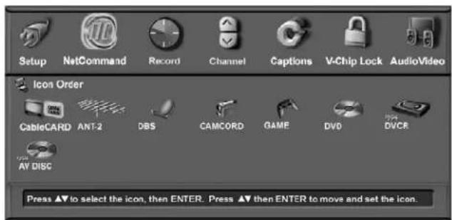
Figure 12. Icon Order Menu
Transport Menu
Figure 13
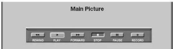
Figure 13. Transport Menu
NetCommand uses the Transport menu to control VCRs, DVDs, IEEE 1394 A/V Discs, digital VCRs, and similar devices. If you choose to turn off this menu when viewing the devices, the transport buttons (rewind, play forward, stop, pause and record) on the TV's remote control will continue to operate these devices. In the Device Selection menu selecting a VCR or DVD Player will automatically display the Transport menu. You can re-display this menu by pressing DEVICE MENU.
Select Transport menu functions by pressing ADJUST ▲, ▼, ◀ and then ENTER. For example, to pause playback, press ADJUST ◀ or ▶ to move to PAUSE, then press ENTER. If a function is not possible, such as record for a DVD Player, the Transport menu button will be grayed out.
Remote Control Transport Buttons
Transport buttons (rewind, play forward, stop, pause and record) on the remote control are located in the bottom section of the remote control.
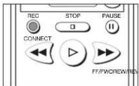
Record Menu
Record
Figure 14
The Record menu allows you to setup recordings, view the record list and set defaults for your recording devices.
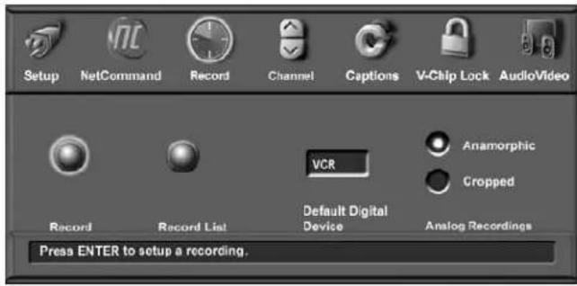
Figure 14. Record Menu
Recording Setup
Figure 15
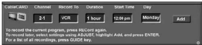
Figure 15. Recording Setup screen
The recording Setup menu is where you tell the TV what, where, and when to record. There are two ways to open the Recording Setup menu:
• by selecting Record from the Record menu.
• by pressing REC on the remote control.
Your TV is able to start and stop recordings automatically and send the signals from one external playback device to another external recording device. It is also able to convert digital channels and IEEE 1394 device signals to analog signals that can be recorded on NetCommand-compatible analog VHS and S-VHS VCRs connected to the record audio and video outputs on the back of the TV.
You can schedule the recording to take place at a later time and program the recording duration for a minimum of 30 minutes and a maximum of 6 hours (in 30-minute increments). The default is 1 hour.
When a digital recording is being made, the TV will either direct the signals to the recording device using the IEEE 1394 cable. In the case of an analog recording (as to a VCR) the TV converts the digital signals to analog format and sends the analog output to the VCR through the RECORD OUTPUT jacks.
During the recording, the TV can be powered Off.
To prevent recording of unwanted material while recording to a VCR or A/V disc, press PAUSE to temporarily stop recording. Press PAUSE again to resume recording.
You cannot record from an analog channel or device or a VHS or S-VHS VCR to a digital recording device such as a DVCR or A/V Disc.
Recording Now
Can be used when viewing Antenna 1 or 2, an IEEE 1394 device, or a non-recording traditional device.
To initiate recording now:
- Press REC (record) on the TV remote or press ENTER if the Record menu is displayed.
- Review the Record To (destination) device (VCR) and duration. Change if necessary.
- Press REC a second time to initiate recording.
Time-Delayed Recording
To initiate a time-delayed recording:
- Press REC (record) on the TV remote or press ENTER if the Record menu is displayed.
- Press ADJUST ▲r to select the channel, device to record to, duration time, start time (press ENTER after selecting hour and minutes to set the time) and day.
- Select Add and press ENTER to add the recording to the record list. If your selection is successful, a confirmation message will be displayed. If you pick overlapping times, day(s), or destination devices, you will see a message stating there is a conflict.
- To exit, press HOME on the TV remote after all recordings have been added.
IMPORTANT
Recordings scheduled on this screen are independent of recordings scheduled through TV Guide On Screen®. Recordings scheduled with TV Guide On Screen have priority if there is a conflict between the two recording schedules.
Record Menu, continued
Record List
Figure 16
To see a list of all currently programmed recordings, select the record list option on the Record menu or press GUIDE while viewing the Recording setup screen. A maximum of 32 recordings can be scheduled. To cancel a recording on the Record List, press ADJUST ▲ or ▼ to select the recording, then press CANCEL. To page through the list, press CH ▲ or ▼
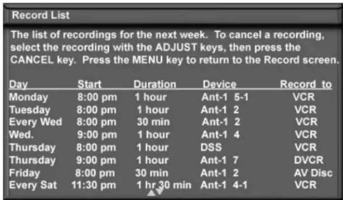
Figure 16. Record List screen
Cancel Current Recordings
To remove a recording from the record list, use ▲ or ▼ to highlight the scheduled recording and then press CANCEL.
Default Digital (Record) Device
If multiple recording devices are available in NetCommand, this setting allows you to choose the device to use when recording digital programs. A digital recording can be made on either a digital or analog device although the quality will not be as good if recorded on an analog device. For best playback quality, record digital programs on a digital recording device.
If multiple devices were not connected and then added in the NetCommand setup, this setting will be unavailable (grayed out). Analog recordings can only be made on the one analog device connected to RECORD OUTPUT (usually a VCR) and are not affected by this setting. This feature is most useful when recording from ChannelView™ (page 53) or when set up from TV Guide On Screen® using the REC key..
Analog Recordings
When you record a 16:9 digital channel to an analog VCR or recording device, there is a mismatch of the picture shape between the 16:9 ratio of the source and the narrower 4:3 ratio of the analog recorder.
- For anamorphic playback on this widescreen TV, choose the anamorphic picture display and ensure that the TV screen format is set to standard (see the section on TV formats in this Owner's Guide).
- For cropped playback on an older style 4:3 TV, choose the cropped display to remove the top and bottom sections. This setting does not affect recording from analog devices, analog channels, or 4:3 digital channels.
Setting Up Analog Recordings with TV Guide On Screen®
When setting up a recording using TV Guide On Screen, note that:
- You must select the desired recording device in the TV Guide On Screen Record Options menu.
- Analog programs can only be recorded to an analog recording device, such as a VCR.
- Analog programs cannot be recorded to digital devices such as A/V discs or DVCRs.
- The destination recording device for analog programs must be the analog device connected to the TV's RECORD OUTPUT jacks.
IMPORTANT
When setting up analog recordings in TV Guide On Screen, you must set the destination recording device as the analog device connected to the TV's RECORD OUTPUT jacks.
Channel Menu
Channel
Figure 17
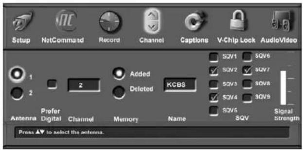
Figure 17. Channel Menu
Antenna
Select the antenna for the channels you want to edit. You can select Ant-1 (main) or Ant-2 (Aux).
Prefer Digital
When a memorized channel number is available as both analog and digital, a check mark in the Prefer Digital box will allow digital channels to display and analog channels to be hidden (when using CH ▲ or ).▼Removing the check mark will show both analog and digital choices.
Channel
Channels can be changed in 3 ways:
- By pressing ADJUST to select the channel.
- By pressing CH ▲ for channels already in memory.
- Directly entering the number. With so many current and potential channels, the number range is greatly expanded. Channels can be one part, analog or digital (up to the number 16383) or two part, for digital channels (these use a separator). For a two part digital channel, you may press SUB/CANCEL on the remote to enter a separator after the first, second or third number, depending on the broadcaster's channel information.
For digital channels, when the broadcaster has sent a virtual channel number, the virtual channel number is shown in the text box and the original digital channel is shown below on-screen, as a reference.
Memory
After the available channels have been memorized with Memorize Channels on the Setup menu, weaker channels can be added or unwanted channels can also be deleted. Press CH ▲ or ▶ on the remote control to see the channels in memory. Press ADJUST ▲ or ▶ to select Added or Deleted for the channel shown in the Channel number box.
Name
Analog channels shown on Antenna-1 or Antenna-2 can be named (up to four characters). After you enter a name, it will appear on the TV screen, next to the channel number.
-
Press ADJUST ▲ to select each letter.
-
Press ENTER to set the letter and move to the next letter position.
-
Press CANCEL to move back one position.
Digital channels are automatically named if the broadcaster sends the information.
Channel Menu, continued
SQV (SuperQuickView™)
Using The Menu Screen
Figure 17
SQV (SuperQuickView™) allows you to put together lists of your favorite channels from Antenna 1 and Antenna
- You can store channels in any of the 9 different SQV memory banks. You can also store the same channel in multiple memory banks. Once you have added a channel to an SQV memory, "SQV" and the memory bank number will appear under the tuned channel number on the TV screen.
Adding SQV Channels
- Select the channel using the "Channel" option box or press CH ▲or .▼
- Highlight the bank (SQV1-SQV9).
- Press ENTER to check mark the selected SQV memory bank.
- Repeat for additional channels or banks.
Removing SQV Channels
- Highlight the box for the SQV bank number.
- Press ENTER to remove the check mark.
SQV (SuperQuickView™)
Using The Remote Control
Viewing and changing SQV banks using the remote control:
- Press the SQV button.
- To change memory banks, press a number button within 5 seconds of pressing the SQV button.
- Press the SQV button repeatedly to cycle through the channels available in that bank.
Adding SQV channels using the remote control:
- Press CH ▲, ∅ number buttons to select the channel you want to add to the current SQV memory bank.
- Press and hold the SQV button for about 2 seconds. When "SQV" and the memory bank number appear under the channel number, the channel has successfully been added.
Removing SQV channels using the remote control:
- Press the SQV button and then the memory bank number.
- Press the SQV button repeatedly until you see the desired channel.
- While the channel number and SQV indicator (with correct bank number) are still displayed on the screen, press the CANCEL button. If the CANCEL button is not pressed before the SQV indicator disappears automatically, the channel will not be removed.
- When the SQV indicator disappears, the channel has successfully been removed only from that bank. "Other" banks remain unchanged.
Signal Strength
Displays the approximate signal strength of the currently tuned digital channel. Use to adjust the antenna direction to optimize signal strength. The higher the bar, the stronger the signal. Does not apply to analog channels.
You can change the tuned channel while in this menu so that you can see the effects of antenna adjustments. Highlight the channel box, press CH ▲▼ ADJUST ▲▼ to display the desired channel number, and press ENTER.
Captions Menu
Captions Menu
Figure 18
For analog channels, broadcasters can send either Standard or Text closed captioning. Standard Closed Captions follows the dialogue of the characters on screen and displays in a small section of the screen. Text Closed Captions often contain information such as weather or news and covers a large portion of the screen.
On digital channels, broadcasters can send up to six different captioning selections or can send analog captions the same as the analog station sound. Each TV station may broadcast only one or two types of captions or none at all. The TV cannot decode Closed Captions received on COMPONENT 1–3 or HDMI 1 or 2.
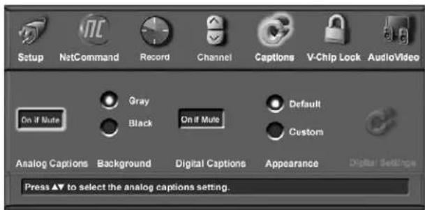
Figure 18. Captions Menu
Analog Captions
The TV can display one of the following captions for Analog sources:
- CC1, CC2, CC3, or CC4. (Standard closed captioning signals).
- Text1, Text2, Text3, or Text4. (Text closed captioning signals).
- On if mute. Closed captions when mute. When selected, the standard closed captioning signal (CC1) will turn on/off by pressing MUTE on the TV remote control.
- Off. No closed captions.
IMPORTANT
When analog text closed captioning is selected, a large black or gray box appears on your TV screen if no signal is broadcast.
Background
To make the analog closed captions easier to read, you can choose to display the background color as either black or gray behind the captions.
Digital Captions
The TV can display one of the following Captions for Digital sources:
- Captions 1-6. Sent by broadcaster.
- On if Mute. Closed captions when mute. When selected, the captioning signal (Caption 1) will turn on/off by pressing MUTE on the TV remote control.
- Off. No closed captions.
Note: If the broadcaster is only sending analog captions converted to digital, then the analog captions settings apply.
Appearance
Closed Captions provider selects the Default options when sending digital closed captions. You may select the Custom option to override and customize Closed Captions appearance. These settings do not apply to analog Closed Captioning converted to digital.
Digital Settings
Figure 19
Select Digital Settings by moving the ADJUST buttons and pressing ENTER allows you to customize the Closed Caption settings that are sent by the broadcaster. Digital settings do not apply to analog closed captions converted to digital.
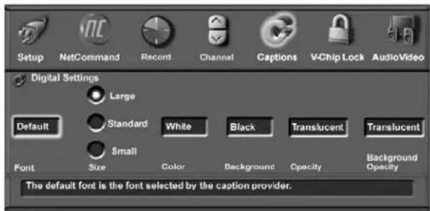
Figure 19. Closed Captions Menu Digital Settings
Captions Menu, continued
Fonts
You can customize the text of digital captions by selecting the font of your choice. The available Font options are as follows:
- Default—Selected by the Closed Captions provider
- Font 1—Monospaced font with Serif
- Font 2—Proportional spaced font with Serif
- Font 3—Monospaced font without Serif
- Font 4—Proportionally spaced without Serif
- Font 5—Casual font
- Font 6—Cursive font
• Font 7—Small Capitals font
Size
You can also customize the text of digital captions by selecting your desired size of font. Large is the recommended font size.
Color
You can customize the text of digital captions by selecting the font color. The available font colors are listed below. Black text is available only when the background is a color other than black.
- White • Yellow
- Black • Green
- Magenta • Cyan
- Red • Blue
Background
To make the digital closed captions easier to read, you can choose the background color. The available background colors are listed below. White background is available only when the text is a color other than white.
- White • Yellow
- Black • Green
- Magenta • Cyan
- Red • Blue
NOTE: Make the font color different from the background color. If both are the same color, the captions text will be invisible.
Opacity (Font)
You can customize the visibility of your fonts using the following categories:
- Translucent—TV program is faintly visible behind the text
- Transparent—See-through text reveals the TV program
- Opaque—Solid color text; blocks the TV program
- Flashing—Text flashing in intervals
Background Opacity
You can customize the background for digital captions using the following categories:
- Translucent—TV program is dimly visible behind the background
- Transparent—See-through background reveals the TV program
- Opaque—Solid background; blocks TV program
- Flashing—Background flashing in intervals
IMPORTANT
We recommend you use contrasting colors between captions and background. In particular, Black background with translucent opacity and White font are easy to read.
Care must be exercised when selecting customized colors. Your choice may change the legibility or readability of captions.
IMPORTANT
The content of captions is determined by the broadcaster. If your captions show strange characters, misspellings or odd grammar, it is not a malfunction of the TV.
V-Chip Lock Menu
V-Chip
Select V-Chip Lock to perform the functions listed below. V-Chip allows you to Block or Allow programs based upon rating signals sent by the broadcaster. The TV comes from the factory with the V-Chip Lock in the Off setting.
You can turn the V-Chip on within the V-Chip Menu or you can use the V-CHIP button on the remote control to conveniently turn the V-CHIP on or off.
The factory preset is TV-PG for TV ratings or PG for movie ratings, allowing only programs rated TV-PG/PG or lower. You can change the blocking level to various TV ratings and lettered categories or movie ratings. After changing channels or devices, there may be up to a 5 second delay before the V-Chip lock takes effect.
IMPORTANT
If you forget your four-digit Pass code, see Appendix A.
Entry
Figures 20 and 21
You will see the screen shown in Figure 20 when you press V-CHIP on the remote control, the first time you select the V-Chip Lock menu, or after you have canceled your pass code. To use the Lock, input a four-digit pass code with the number buttons on the remote control, then press ENTER. You can delete a number and move back one space by pressing CANCEL. You can exit without inputting a pass code by pressing MENU or HOME.
After setting a pass code, the V-Chip Lock is active. The next time you select V-Chip Lock you will see “...enter your pass code” instead of “...enter a new pass code.”
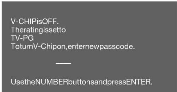
Figure 20. V-Chip Entry screen
To view a V-Chip blocked program or to watch the program during a scheduled lock time, you must enter your four-digit pass code or change the channel to an unlocked program. Once you have entered the pass code, the V-Chip block for that channel or Lock by Time will remain released until the TV is powered Off and then On again.
Channelislocked.
V-Chiplockedtheprogrambecausetheratingis
TV-PGDSLV
Towatchtheprogram,Enteryourpasscode.
UsetheNUMBERbuttonsandpressENTER.
Figure 21. V-Chip pass code screen
V-Chip Start Time and V-Chip Stop Time
Figure 22
Select the times you would like the V-Chip to be active. By setting the V-Chip Start Time and V-Chip Stop Time to the same time, the V-Chip will be active 24 hours a day. Press ADJUST ▲r t▼ slowly select the time, starting with the hours. Press and hold ADJUST ▲r t▼ quickly select the hours, press ADJUST ▲o select the minutes.
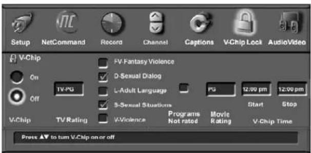
Figure 22. V-Chip Menu, Start & Stop Time
V-Chip Lock Menu: V-Chip Definitions
V-Chip Signal Information
When provided by the broadcaster, V-Chip ratings can be used to control which programs can be viewed or will be blocked. When V-Chip ratings are sent, you will see the ratings when you change the channel or when you press the INFO button on the remote control. Both TV and Movie ratings will display. TV ratings apply to programs and movies developed for TV and may have supplemental blocking by content categories. Movie ratings use MPAA ratings for movies released in theaters.
V-CHIP EXCEPTIONS:
- V-Chip is not effective for programs viewed on devices connected to component inputs or HDMI.
- Videotapes, laser discs and DVDs may not contain V-Chip rating signals. If they don't contain the V-Chip signal, V-Chip cannot block the program or movie.
- Broadcasters are not currently required to include V-Chip rating signals at this time. If the broadcaster does not include the V-Chip rating signal, V-Chip cannot block the program.
TV Ratings:
Used with TV programs and Made-for-TV movies.
TV-Y Youth, for children under the age of 7.
TV-Y7 Youth, 7 years old and older. For children 7 years old and older.
TV-G General Audience. For the entire family to view.
TV-PG Parental Guidance. Parental Guidance is recommended, may not be suitable for some children.
TV-14 Adolescent 14 years old and older. Not recommended for children under the age of 14.
TV-MA Mature Audience. For adults only.
| TV Rating | FV | D | L | S | V |
| TV-Y | |||||
| TV-Y7 | X | ||||
| TV-PG | X | X | X | X | |
| TV-14 | X | X | X | X | |
| TV-MA | X | X | X |
Content Categories:
Used in association with the TV ratings above.
FV Fantasy Violence—applies to TV-Y7 only.
D Sexual Dialog—applies in different degrees to TV-PG and TV-14.
L Adult Language—applies in different degrees to TV-PG, TV-14, and TV-MA.
S Sexual Situations—applies in different degrees to TV-PG, TV-14, and TV-MA
V Violence (graphic or realistic)—applies in different degrees to TV-PG, TV-14, and TV-MA.
When you select a TV rating, you are selecting the least-restrictive program level that can be viewed. For example, if you select TV-PG, you are allowing programs rated TV-Y, TV-Y7, TV-G and TV-PG to be seen and blocking programs rated TV-14 and TV-MA. When you select a TV Content category, you will block all TV programs that have the same content category listing. For example, if you select to block V (Violence) at the TV-14 level, you will also block any program that has the V category listing at the TV-PG rating level as well.
Movie Ratings:
Used with theater released movies and direct-to-video movies.
G General Audience—Designed for the entire family to view.
PG Parental Guidance—Parental Guidance is recommended, may not be suitable for some children.
PG-13 Parental Guidance 13 years old and older—Not recommended for children under the age of 13.
R Restricted—Restricted in the theater to 17 years old and older unless accompanied by an adult.
NC-17 No Children—Restricted in the theater to 18 years old and older.
X Adult—Designed for and restricted in the theater to adult audiences only.
When you select a movie rating, you are selecting the least-restrictive program level that can be viewed. For example, if you select a movie rating of PG-13, you are allowing movies rated G, PG and PG-13 to be seen and blocking movies rated R, NC-17, and X.
Programs Not Rated: Used for programs that are not rated, such as news, sports, weather, emergency bulletins, or movies prior to or without MPAA Ratings. This does not include programs without V-Chip signals.
IMPORTANT
If you select to block programs that carry the V-Chip rating "Programs Not Rated," you may block News or Emergency Bulletins, when "None" or "NR" Not Rated V-Chip rating is included. Use care when blocking programming that is not rated.
V-Chip Lock Menu, continued
Lock By Time
Figure 23
Lock by Time allows you to lock the entire TV during specific hours. During the Lock Time, you must use your pass code to view the TV. To enable the lock:
Press ADJUST ▲ or ▶ to select On or Off, then press ADJUST ▶ to move to the Lock Time box. Press ENTER. Press ADJUST ◄ or ▶ to select Lock Time.
Press ADJUST ▲ or ▼peatedly to slowly select the hour or press and hold to quickly select the hour. Press ENTER to move to the minutes options. Press ADJUST ▲ or ▼to select minutes, then press ENTER to select AM or PM
Setting the Lock Time and Unlock Time to the same time will make the Lock by Time active 24 hours a day.
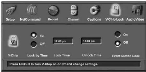
Figure 23. V-Chip Menu, Lock by Time
Front Button Lock
Front Button Lock lets you disable controls on the front panel to prevent anyone from changing settings by accident.
Select ON to lock out the operations of the front panel buttons and select OFF to restore the operations of the front panel buttons.
If the front panel buttons have been locked and you misplaced the remote control, you can restore the function of the front panel buttons by pressing and holding the MENU button on the front panel for more than 8 seconds. If the TV is already on, a message will be displayed to confirm the release of the Front Button Lock.
Audio/Video Menu
Audio/Video
Figure 24
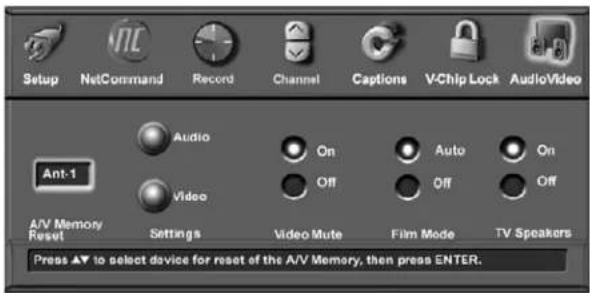
Figure 24. Audio/Video Menu, Settings
A/V Memory Reset
A/V Memory Reset allows you to select the device which will have the A/V Settings returned to the original factory settings. To return a device's memory to the original factory settings, select the device and then press ENTER.
Settings
Each device has its own A/V memory. Select the device in A/V Memory Reset, then select Audio or Video to adjust the device's individual settings. Press ENTER, and the menu is removed and the individual settings are displayed.
Use ADJUST ▲ or ▶ select the individual settings to be adjusted. Use ADJUST ▶ or ▶ make the adjustment. For descriptions of the individual A/V settings see A/V Setting Descriptions, pages 78 and 79.
Video Mute
Video Mute lets you display a blue background when no signal is being received on Inputs 1–3 and COMPONENT 1–3.
Film Mode
Auto is the default setting and will automatically detect and apply film decoding correction for signals that originated on 24 frames per second film cameras and then were converted for broadcast to 30 frames per second video.
When the original signals originated on 30 frames per second video cameras, the Auto setting will automatically apply video decoding, the same as used with the Off setting. Try the Off setting when the TV seems to have difficulties and adds too many jagged edges to the images.
Film Mode is not effective for high definition signals.
TV Speakers
When an A/V receiver has not been set up in NetCommand, this selection will turn the TV's internal speakers on or off. You may select Off when sending the sound through a separate stereo system or surround sound A/V receiver.
This option is unavailable (grayed out) when NetCommand ^® is enabled and you have selected the A/V receiver icon from the Device Selection menu. In that case, Netcommand automatically turns the TV speakers off. See the NetCommand information for further instructions.
Note: To prevent damage from a sudden increase in volume, make sure the TV volume is set to low before setting speakers to On.
Using the AUDIO or VIDEO Button on the Remote Control
To adjust individual Audio or Video settings directly with the remote control:
- Press AUDIO or VIDEO to cycle through the available settings.
- Press ADJUST ▶ t▶ adjust the setting. After 5 seconds of inactivity, the setting display will disappear.
A/V Setting Descriptions: Audio
NOTE: The effects of the Audio Settings of Bass, Treble, Balance and Surround affect the sound heard through the TV speakers only.
Analog and Digital Audio Settings
A slider displays on screen for most settings. When the slider is displayed, it has a numeric value, so that 63 is the maximum, 31 is the mid-point, and 0 is the minimum.
◇ Bass
Enhances or reduces low-pitched sound.
Treble
Enhances or reduces high-pitched sound.
Balance
Adjusts the level of sound between the left and right speakers.
◇ Surround
Creates simulated stereo and surround effects through the TV speakers. Your choices are:
- Off: No surround effects.
- Simulated Stereo: Your TV will create a simulated stereo effect when watching a non-stereo program.
- Surround Sound: Your TV will create a simulated surround effect when watching a stereo program.
◇ Level Sound
Turn On or Off to automatically equalize the volume level of programs containing significant level differences from one segment to another (for example, regular programming to commercials). To receive the best fidelity with music programs, you can turn this setting to Off. When connecting to an A/V receiver, set level sound to OFF and turn the TV speakers off to send full dynamics to the A/V receiver.
Analog-Only Audio Settings
◇ Listen to
Determines how your TV will receive a broadcast audio signal and play back the sound you hear.
Your choices are:
- Stereo: Default setting. The TV will play stereo broadcasts in stereo and mono broadcasts in mono. The word "Stereo" will be displayed when you tune to a channel broadcasting stereo.
- SAP (Second Audio Program): Additional monaural sound track that you cannot hear during normal TV viewing. The SAP signal might be related to the program you are watching,
such as a sound track in a foreign language, or unrelated to the program you are watching, such as a weather report. If an SAP signal is broadcast, the letters "SAP" will be displayed when you tune to the channel.
- Mono: Reduces background noise and should be used when receiving a weak stereo audio signal. All audio will be played mono with this setting.
Listen to is not available for devices connected to the TV Inputs, component inputs or 1394 devices.
Digital-Only Audio Settings
◇ Language
Determines what possible language you will hear. Your choices are:
- English • Portuguese
- French • Spanish
- German • “Other”
- Italian
IEEE 1394 Amplifier Settings
Balance
Adjusts the level of sound between the left and right speakers. The slider range is 0 - 254, with 127 at the center.
◇ Loudness
Set to On to make the audio level more uniform.
◇ Preset
Select the mode that matches the audio source. Your choices are:
- Off • Classical Music
- Jazz • Movie
- Rock • Speech
◇ Equalizer
Equalize the sound.
A/V Setting Descriptions: Video
Video Settings
Press the VIDEO key repeatedly to cycle through Video options to the one you want to change. Use ADJUST
▶ to change settings.
Bright/Natural Modes
Bright and Natural modes are available for some settings and allow you to optimize the image for a brighter (daytime) or dimmer (nighttime) viewing environment. To do this, your TV remembers two independent Contrast, Brightness, and Color Temperature settings, one for each of the two modes. Whenever you change settings for Contrast, Brightness, or Color Temperature, first check which of the two modes (Bright/Natural) is active.
◇ Contrast (Bright/Natural)
Provides a slider to adjust the white-to-black level. Low contrast shows a variety of shades in darker images, while high contrast shows darker images more uniformly black and makes colors appear more vibrant. In most home lighting situations, a medium contrast looks best. High contrast is good for brightly lit environments.
◇ Brightness (Bright/Natural)
Provides a slider to adjust the overall brightness of the picture.
◇ Color
Provides a slider to adjust the color intensity.
◇ Tint
Provides a slider to adjust the ratio of red to green.
◇ Sharpness
Provides a slider to adjust the detail and clarity.
◇ Color Temp (Bright/Natural)
Allows you to adjust how white images are displayed. Your choices are:
- Low: White images will have a warm cast to them. This adjustment is an average and can vary due to ambient room lighting, video scene brightness and the TV's age.
- High: White images will have a cool cast to them. This setting may provide the most realistic picture under bright lighting.
The Bright and Natural Color Temp adjustments have high and low settings. Natural/Color Temp at the low setting displays video at the 6500K industry standard for NTSC pictures.
PerfectColor™
Adjusts any or all of six colors (Magenta, Red, Yellow, Green, Cyan and Blue) to create color balance. When you select PerfectColor and press ENTER you can adjust the colors automatically or manually (individually).
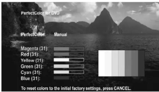
Individual sliders for each color will be displayed. Highlighted text will show which slider you are adjusting. Each TV input or device has a memory for PerfectColor. While using the PerfectColor option, press CANCEL if you want to reset the colors to the default settings.
◇ Video Noise
Use to reduce minor noise (graininess) in the broadcast received on Ant-1 and Ant-2, Inputs 1-3, and Component 1–3. Use standard with good-quality signals.
NOTE: A slider displays on screen for most settings. When the slider is displayed, it has a numeric value, where 63 is the maximum, 31 is the mid-point and 0 is the minimum. For a Currently Viewed PC Connected to HDMI-2
A/V Setting Descriptions: Video, continued
Auto Position
Press ENTER to automatically center the position of the PC video. This can be used whether the PC video is on the main or PIP screen.
◇ HorizPosition (Horizontal Position)
Manually adjust the horizontal position of the PC, either on the main or PIP screen. This selection overrides the Auto Position selection.
◇ VertPosition (Vertical Position)
Manually adjust the vertical position of the PC, either on the main or PIP screen. This selection will override the Auto Position selection.
◇ Fine Detail
Manually adjust the picture quality of the PC, either on the main or PIP screen. This selection overrides the Auto Position selection.
Chapter ...

Additional Features
Operation of PIP 82
TV Display Formats. 83
PC Viewing 85
PC Display Formats 86
MediaCommand™ and Media Card Playback 87
Operation of PIP
You can display programs from analog channels, analog inputs, or devices as Picture-In-Picture (PIP). The TV has a second analog tuner for non-scrambled analog channels received on ANT-1 and will display them as the PIP sub-pictures. Digital channels and devices can be shown as the main picture but cannot be the sub-picture. PC screens can be viewed as the main picture with large PIP.
Press PIP to activate the PIP option. With each press of the PIP button on the TV remote control (within seconds of each other), the PIP will cycle through the following display options:
| MAIN PICTURE | Side-by-Side |
- Side-by-side pictures
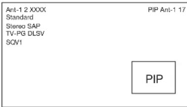
- PIP (available for PC viewing)
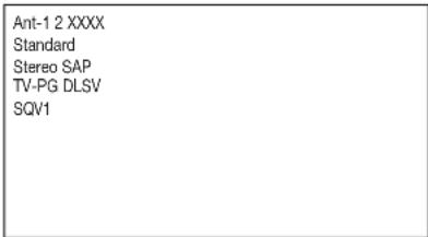
- PIP off
To turn PIP off, wait at least 10 seconds and then press PIP. The next time you activate PIP, the last-used PIP option will be displayed.
Changing PIP Device
When PIP is displayed, press PIP DEVICE to change the PIP picture source device. A menu similar to the Device Selection menu will be displayed.
Changing PIP/Side-by-Side Channels
Press PIP CH to scroll up and down through memorized channels on ANT-1 and ANT-2.
Exchanging Program Images
Press EXCH to exchange the main picture and the PIP picture. Pictures from digital channels can only be
shown as the main picture. PC images can only be the main image.
Moving PIP Image
If no menus are on screen, press ADJUST ▲, ▼, or to ▶ move the PIP display anywhere on the main screen.
Freezing the PIP and Side-by-Side Pictures
Press PAUSE to freeze the PIP and side-by-side images. Press PAUSE again to return to a "live" image.
IMPORTANT
- The side-by-side option cannot show the same channel or device on both sides.
- If ANT-1 or ANT-2 is the main picture, ANT-2 is not available as a PIP or side-by-side image.
- PIP is not compatible with signals from media cards.
- You can view only one HDMI input at a time with the PIP or side-by-side feature.
TV Display Formats
This is a widescreen TV, also known as a 16:9 TV. This shape reflects the new types of images available from HDTV and many DVDs. There are still many older style narrow-screen images (called 4:3 aspect ratio) you will encounter. While there will never be a perfect solution for displaying a narrow image on a wide screen, Mitsubishi offers several display formats from which to choose.
Press FORMAT on the TV remote control to cycle through the available display formats. The last-used format for each device is used when you return to that device.
Note: Not all formats are available for PIP. Side-by-Side is only available in Standard and Expand formats. PC formats vary depending on PC signal.
DVD Definitions:
Anamorphic (or Enhanced for Wide-Screen TV's): These DVDs are recorded in a special way to properly show wide-screen images on 16:9 TV sets in the Standard format mode. This is the recommended choice.
Non-Anamorphic (or 4:3, 1:33:1, Letter box or Full Screen):
These DVDs are recorded for use with traditional shaped TVs. They may be full screen (4:3 or 1:33:1) which crops movies to fit the narrow TV, or Letter boxed, which adds black top and bottom bars.
This information may or may not be listed on the DVD case. Some DVDs support both types of recordings.
Signal and Format Definitions:
480i Signals: Traditional analog interlaced signals from or through ANT-1 and 2, INPUT 1 and 2, COMPONENT 1-3, and HDMI 1 and 2.
480p Signals: Progressive-scan analog DVD signals on COMPONENT 1-3 and HDMI 1 and 2.
720p & 1080i Signals: High-definition analog signals received through COMPONENT 1-3, and HDMI 1 and 2. These signals are always 16:9 (wide screen).
SD 4:3: Standard-definition narrow-screen format signals from digital channels and IEEE 1394 devices.
SD 16:9: Standard-definition wide-screen format signals from digital channels and IEEE 1394 devices.
HD: High-definition wide-screen format signals from digital channels and IEEE-1394 devices. These signals are always 16:9 (wide screen).
Standard: This is the full-screen format. HDTV signals use this format. This format is useful for displaying Anamorphic DVDs that have 1.78:1 or 1.85:1 aspect ratios. Anamorphic DVDs that have a 2.35:1 aspect ratio are displayed with black bars at the top and bottom, but show the entire image correctly. Narrow (4:3) images are stretched evenly from side to side. Available for all signals.
Expand: This enlarges the picture to fill the screen, cropping off some of the image at the top and bottom. This is useful for reducing the letter box top and bottom bars of non-anamorphic DVD images. Available for analog 480i, 480p and digital SD 4:3 signals only.
Zoom: This enlarges the picture, cropping off some of the image at each side and top and bottom. This is useful for removing or reducing the black top and bottom bars on anamorphic DVDs with a 2.35:1 aspect ratio. Available for analog 480i and 480p and SD 4:3 signals only.
Stretch: This format stretches a narrow (4:3) image across the screen, however, there is less stretch in the center than at the sides. This allows the entire narrow image to be displayed across the screen with less distortion than is seen in the Standard format. Available for analog 480i and 480p and SD 4:3 signals only.
Stretch Plus: Similar to stretch mode, however, to minimize distortions on the side, the picture is expanded to crop off portions of the top and bottom. When no PIP is displayed, you can press ADJUST up or down to vertically adjust the position of the picture. Available for analog 480i and 480p and SD 4:3 signals only.
Narrow: This format will display narrow (4:3) images in their original shape, and add stationary black side bars to fill the screen. Available for 480i, 480p and digital SD 4:3 signals only.
Wide Expand: Enlarges the picture, cropping some of the image on both sides. This Expand format is useful to remove or reduce black side bars added to narrow images that are converted to 16:9 signals for digital broadcast. Available for analog 1080i, 720p, digital SD 16:9 and digital HD signals.
TV Display Formats
ORIGINAL SIGNAL
Non-anamorphic or SD 4:3
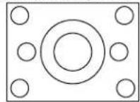
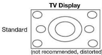
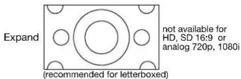
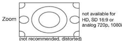
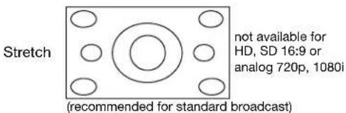
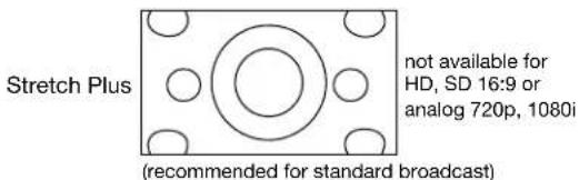
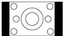
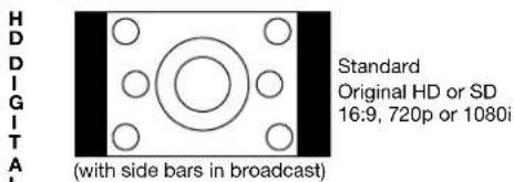
ORIGINAL SIGNAL
Anamorphic DVD
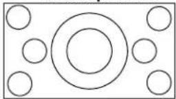
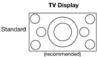
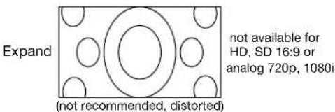
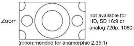
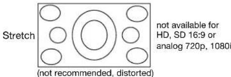
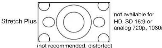
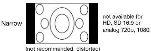
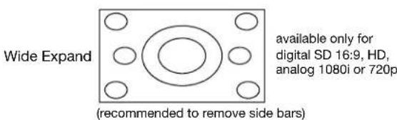
PC Viewing
Figure 1
To display your PC screen on the TV, first connect the PC to the HDMI 2 input on the TV's back panel (see Chapter 2). You must then activate the PC option in NetCommand. You can do this during initial NetCommand setup (in the Device Setup screen), or at any time afterwards by using the NetCommand Add function. You will then be able to select the PC through the Device Selection Menu. For the correct screen resolution (pixels), use the PC's Control Panel settings.
Your Mitsubishi TV can display resolutions from standard VGA (640 x 480) through XGA 60-Hz refresh rates only. See Appendix B in this book for more screen resolutions. The instructions below are for most PCs.
- In the PC's "Start" menu, select "Settings."
- Select "Control Panel."
- Select "Display."
- Choose the "Settings" tab.
- Depending on your PC, either:
Use the Screen area slider or use the Screen Resolution slider to adjust the resolution.
You may need to restart the PC for this change to take effect.
Hint: You may want to set the computer's screen saver to a pattern, to display after several minutes, as a reminder that the TV is still powered on and time is being added to the lamp's elapsed hours. Even if the screen appears dark, if the TV's power is on, the lamp is in use.
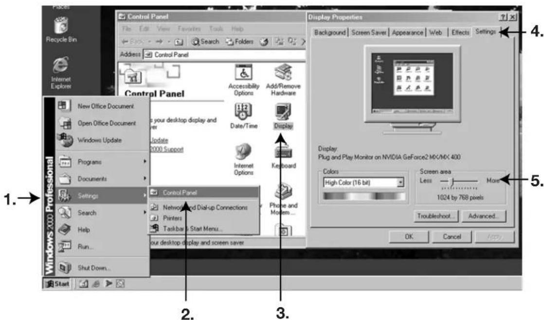
Figure 1. PC resolution XGA selection
PC Display Formats
| Signal FormatOriginal Pixel Counts | 16 X 9 Standard 4 X 3 | Standard |
| VGA640 X 480 | 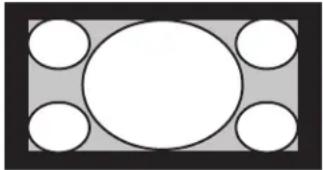 1696 X 960 1280 X 960 1696 X 960 1280 X 960 | 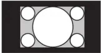 |
| WVGA848 X 480 | 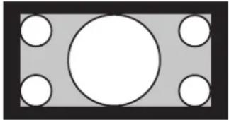 1696 X 960 1280 X 960 1696 X 960 1280 X 960 | 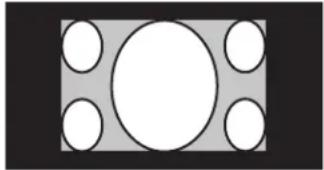 |
| SVGA800 X 600 | 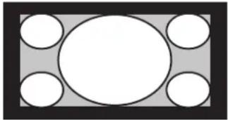 1702 X 960 1280 X 960 1702 X 960 1280 X 960 | 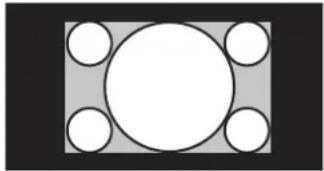 |
| WSVGA1064 X 600 | 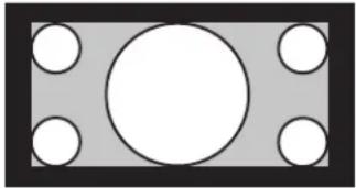 1702 X 960 1280 X 960 1702 X 960 1280 X 960 | 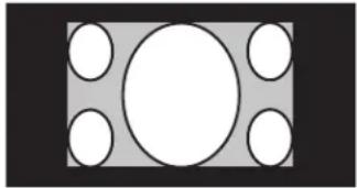 |
| Signal FormatOriginal Pixel Counts | Standard Zoom | |
| XGA1024 X 768 | 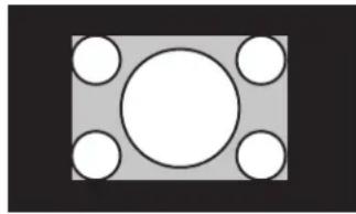 1024 X 768 1024 X 768 | 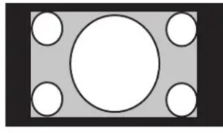 1280 X 960 1280 X 960 |
| PC720p1280 X 720 | 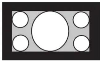 1280 X 720 1280 X 720 | 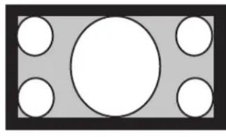 1706 X 960 1706 X 960 |
MediaCommand™ and Media Card Playback
Warning: Some media cards available on the market are not properly certified to follow the card type specifications noted below and cannot be used by the Card Reader. If you experience problems with the reading of your file, please transfer your files to a properly certified card.
Media Card Slots
Inserting a media card
- Insert a card into a matching card slot on the front of the TV. Be sure to use the correct card slot.
• Card 1 accepts SmartMedia™.
- Card 2 accepts MultiMediaCard™ and SD Media Card.
Card 3 accepts CompactFlash® and MicroDrive®.
- Card 4 accepts MEMORY STICK™ and Memory Stick Pro. Cards up to 1GB, with a file format of FAT 16 (block size = 1024 or 2048) are supported.
Normally the label side should be up, but if the card does not fit, try turning the card over and insert again. When properly inserted, the light next to the slot lights up.
- Press DEVICE on the remote control to display the Device Selection Menu and then select the correct card slot from the list, using ADJUST ▲▼.◀▶
- The Media Dialog box (figure 2) will automatically display. Use the AUDIO button to switch from JPEG Picture Slide show setup to MP3 or WMA7 Audio Play list setup or use the VIDEO button on the remote to switch from the MP3 or WMA Audio Play list setup to JPEG Picture Slide show setup.
Don't pull the media card out while it is playing.
ForSlideshow,pressPLAY. ForThumbnails,pressGUIDE. Toredisplaythismenuorto setup,pressDEVICEMENU.
ForPlaylist, pressAUDIO.
Figure 2. Media Dialog Box
- On the remote control, press:
PLAY: to start the slide show or play audio.
GUIDE: to display the JPEG Thumbnail menu (Figure 3) or Audio track play list (Figure 4)
DEVICE
MENU: to display the Media Setup menu (Figure 5).
Remote Control Buttons for Controlling the Playback
For JPEG Pictures Slide show:
PLAY: begins or resumes slide show playback
PAUSE: pauses or resumes playback while in the automatic advance mode.
FF: skips to the next slide.
REW: returns to the previous slide.
FORMAT: single press rotates the slide 90°. Multiple presses continue to rotate the slide.
STOP: Stop slide show, return to media card screen.
For MP3 or WMA Audio Playback
PLAY: begins or resumes play list playback.
PAUSE: pauses or resumes playback.
FF: skips to the next track/song.
REW: skips to the previous track/song.
STOP: Stop playback and returns to media card screen.
Using the Picture Thumbnail Menu or Audio Play list Menu
For JPEG Picture Thumbnail Menu:
Figure 3
- Press GUIDE on the remote to display the JPEG picture Thumbnail menu.
- Press ADJUST ▲▼to move the highlight to different images (CH up/down will change pages of the Thumbnail menu). Use REW to go to the first slide and FF to go to the last slide on the page.
- Press FORMAT to rotate the selected image 90^ (pressing FORMAT four times will rotate the image completely around to the original position).
- Press PLAY to begin playback of the Slide show from the selected image. The Thumbnail menu will be taken down.
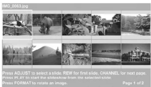
Figure 3. JPEG Thumbnails
Media Command™ and Media Card Playback, continued
For MP3 or WMA7 Play list Menu:
Figure 4
- Press GUIDE to display the Play list menu.
- Press ADJUST ▲ to select different tracks (CH up/down will change pages of the Play list).
- Press PLAY to begin playback. The Play list menu will be taken down. The song currently playing will be highlighted.
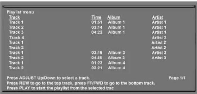
Figure 4. Audio Play list
COMPATIBLE PICTURE OR AUDIO FILES:
For JPEG Pictures up to 1 GB:
- Still images recorded on digital cameras using the Exchangeable Image File Format, version 2.1 (EXIF 2.1) standard for digital still cameras and Design Rules for Camera File Systems version 1.0 (DCF 1.0)
Some images opened and resaved on a computer may not play back or may not be able to display a picture in the thumbnail list because the computer program that opened and resaved the images changed the file to an incompatible format. - Standard digital images with a maximum size of 5-megapixels for each image, or 2560 x 1920 pixels. Pictures will be scaled to the TV display. Some pictures may be cropped to fit.
- Full path file names can be no longer than 50 characters and must end in a .jpg extension. Not all 50 characters will display.
Images larger than 256MB can take a longer initial time to display.
For MP3 or WMA7 Audio files:
- Files recorded with sampling rates of 32 kHz, 44.1 kHz or 48 kHz.
- Files recorded with fixed bit rates
- File names with .mp3 or .wma extensions
NOTE: During MP3 or WMA7 audio playback, audio from the cards will be sent to the A/V receiver as analog audio. Digital out is not available.
Media Setup Menu
Figure 5 Press DEVICE MENU at any time to display the Media Setup screen, where you can adjust the Slide show Display, Frequency, Interval or Play list Frequency.
For JPEG Picture Slide show Setup
- For JPEG picture Slide show playback, select Automatic or Manual advance. For manual operation, press PLAY or ENTER on the remote control to advance each slide.
- For automatic advance, select the frequency or number of times to show the complete slide show, Once, Twice or Continuously.
- For automatic advance, select the interval time each slide is shown, for example, 5 seconds, or 30 seconds
For MP3 or WMA7 Audio Play list Setup
- Select the frequency or number of times to play the complete play list. Once, Twice or Continuously.
To exit, press DEVICE MENU on the remote control to redisplay the media card screen.
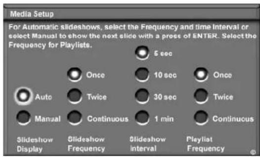
Figure 5. Media Setup Menu
IMPORTANT JPEG images cannot be edited through the TV. Only name changes should be made on your PC to avoid file incompatibility problems.
MP3's must have at least 32 kHz sampling rate.
Chapter ...

Troubleshooting
Troubleshooting
Problem
Possible Solution
| 1. The TV remote control does not work. | Check that the batteries are installed correctly.Check that the selected switch is set to “TV.”Be no more than 20 feet from the TV when using the remote control.Program the remote control to operate the TV (Appendix C). |
| 2. The TV takes several seconds to respond. | It is normal for digital channels to take longer to tune in.Press ENTER after a channel number to avoid delays.Use a 4-digit number for an over-the-air digital channel.Use a 6-digit number for cable digital channels. |
| 3. Cable provider needs information to start CableCARDTM service. | On the remote control, press TV MENU and then enter the numbers 999 to display the Host ID and CableCARDTM ID information. |
| 4. You cannot access a channel. | Use number keys instead of CHANNEL up/down.Be sure the channel you want to view is in memory. See page 65.Check that the TV is turned to the correct device or antenna for that channel by pressing the DEVICE button.Make sure the V-Chip lock is off.If tuned to Digital channels, have physical channel in memory. |
| 5. On-screen displays appear each time you change a function. | This is part of normal TV operation. |
| 6. You cannot program the TV to turn on automatically (timer function) | The TV may be locked.The clock may not be set. |
| 7. There is no sound even when the volume is turned up. | Check audio source in Device Menu.Check to see if the MUTE button is on.The TV’s “Listen to:” setting may be set to SAP.Check that the “TV Speakers” setting is On in the Audio/Video menu. |
| 8. NetCommand unable to learn specific device keys. | Device does not use IR format for remote control signal. ITT and RF formats cannot be learned.Room lighting may affect the signal. Have the remotes very close (6 inches or less) to the TV during Learning.If using a Mitsubishi remote control, make sure slide switch is not set to TV position.Some, but not all, device key functions can be learned by NetCommand. For example, POWER and PLAY may be learned, but other functions may notThe signal from the remote control may not be strong enough. Insert fresh batteries and try Learning again. |
| 9. You have forgotten your V-Chip pass code. | See Appendix A, Bypassing the V-Chip Lock. |
| 10. Lamp indicator light is a constant red. | Turn the TV off for at least 2 minutes. Turn back on. If light is still red, the lamp has failed. Replace it. See Appendix H for lamp replacement information. |
| 11. Lamp indicator light is a constant yellow. | Lamp may fail soon. Purchase a new lamp. See Appendix H for lamp replacement information. |
| 12. Lamp indicator light is a flashing yellow. | Lamp cover door is open or lamp cartridge is not secure. See Appendix H for lamp replacement information. |
| 13. Status indicator light is a constant yellow. | Room temperature has exceeded proper levels. Cool the room. |
| 14. Status indicator light is a constant/flashing red. | Service is required. Contact your dealer or a Mitsubishi Authorized Service Center to arrange for a service evaluation. Listings of Mitsubishi Authorized Service locations can be obtained from our web site, www.mitsubishi-tv.com or by calling 1-800-332-2119. |
| 15. PIP does not display a picture. | Make sure the V-Chip lock is off.Not all inputs can be displayed as a PIP. |
| 16. Digital channels do not appear in PIP. | Normal PIP operation. |
| 17. The sound does not match the screen picture. | NetCommand® is set up incorrectly.The TV’s “Listen to:” setting may be set to SAP.If using stereo or A/V receiver speakers, check their input selection.If using stereo or A/V receiver, check that AUDIO OUTPUT on TV’s back panel is connected to the A/V receiver. |
| 18. There is a large black or gray rectangle on the screen. | The TV's analog closed captioning has been set to "text" mode in the Captions menu. Turn off because there is no text information being broadcast. |
| 19. You cannot see a picture when playing a VHS tape. | Display the Device Selection menu and select the correct VCR.Check your VCR's owner's guide for further troubleshooting. |
| 20. V-Chip is not working. | Make sure that V-Chip is On.If V-Chip Hours are currently set to disable the V-Chip lock, the V-Chip will not block programming. |
| 21. The TV will not turn on after being plugged in. | If green light on front panel is blinking, wait for at least one minute for the light to turn off, then press Power again. |
| 22. TV functions do not respond to the remote control or to front panel control and will not Power Off. | Use the System Reset button . |
| 23. Name options not available for some channels. | Only memorized analog channels can be named. |
| 24. When viewing a stopped VCR, white lines are rolling on the screen. | Turn off video mute for the VCR.Begin playing the tape.Change the VCR input to the antenna input. |
| 25. TV turned itself Off and the light on the front panel started to blink. | Momentary power fluctuation caused the TV to turn off to prevent damage. Wait for the green light to stop flashing and turn On again.If the TV does not stay turned On, use the System Reset button. If this happens frequently, obtain an AC line power conditioner/surge protector.An unusual digital signal may have been received, triggering a protection circuit. Wait for the light to stop flashing and turn TV on. |
| 26. When a device is selected from the Device Selection menu, the screen is blue (no signal source). | Make sure the selected device is turned on.From the Edit NetCommand® menu select Review setting. Verify that the inputs are actually connected to the TV . If they are not, either change the physical connections on the back panel, or select the Change setting on the Edit NetCommand menu to change the TV NetCommand's settings for the connection.Begin play of the VCR. |
| 27. The device does not respond to button presses from the remote. | Remote has not been set up for NetCommand® use.The incorrect manufacturer was selected during setup. Select the Change setting from the Setup menu and then the device to display the manufacturer selection. Change if necessary.The device is not supported and keys have not been learned.The requested function is not supported by NetCommand. Verify that the function is supported or keys are learned.The IR emitter is incorrectly placed. Make sure the IR emitter is facing the IR sensor in the device.The IR emitter is not plugged into the IR emitter Output NetCommand.The IR emitter is facing the TV screen, causing double signals. Be sure that the IR emitter cannot send to the TV. |
| 28. The A/V Receiver is the selected audio source but there is no sound. | Check to see if the A/V Receiver power is turned on. After the power is turned on redisplay the Device Selection menu and press ENTER to allow NetCommand to correctly select the A/V Receiver input.From the Setup Menu, select Review setting. Check the Review screen to see if the A/V Receiver inputs and device correspond to the actual connections on the A/V Receiver. If they do not match, either change the physical connections or change the Netcommand setup. To change the NetCommand setup, select a different program source and then change the audio source to the TV speakers. Next select the Change option on the Edit NetCommand menu to change the device on the Connection screen. |
| 29. The TV Speaker icon or A/V Receiver icon is grayed out and not selectable. | Select the Change setting from the Edit NetCommand menu, and then select the device (for example VCR). Once the Connection screen is displayed, check if the audio check box is selected for the TV input and/or AVR input. |
Troubleshooting, continued Problem Possible Solution
| 30. | Devices are grayed out in the Device Selection menu or the PIP Selection menu. | A recording is in progress requiring the use of RECORD OUTPUT jacks. Cancel the recording to select the device.Digital channels and media cards cannot display in the PIP. |
| 31. | Cannot see the A/V Receiver menu. | The A/V Receiver is not connected to any input of the TV. To check the A/V Receiver menu, temporarily plug into an unused input of the TV. Then select Review from the Setup Menu, turn the input On to view the A/V Receiver menu. |
| 32. | Screen is black when trying to view digital channels or IEEE 1394 device. | The PerfectColorTM color balance has been incorrectly set. Use the Advanced menu to reset the color balance. |
| 33. | The REC button is not working, or, on the Transport menu the record key is grayed out and not available. | The device does not support recording, such as a DVD player.Recordings cannot be initiated from the Transport menu when using an IEEE 1394 device. Press REC instead. The Record menu displays allowing setup of a recording. |
| 34. | A program recorded on your TV is distorted when played on a 4:3 TV. | TV was set to Anamorphic when program was recorded. Record programs in Cropped mode if playing back on a 4:3 TV. |
| 35. | Excessive digital artifacts when viewing an IEEE 1394 device. | The IEEE 1394 cable is too long (15 feet between devices is the maximum length).There may be a slow device in the middle of the IEEE 1394 network. Move the slow devices to the end so that connections for faster devices do not pass through them. |
| 36. | Cannot see a picture from a DV Camcorder. | Go to Device Selection menu and select analog connection.Connect the DV Camcorder to analog input (for example, Input-3). Select Setup from the main menu, then Change. At the Change screen, select the camcorder. On the Name screen, check Analog Connection. Select the device and on the following screen, select which analog input was used, and check audio and/or video. |
| 37. | DVCR analog/digital problems. | If the tape is currently playing but no picture displays, there may be a mismatch of the media with the display. Press DEVICE to display the Device Selection menu. Press ENTER for the DVCR device. If digital is selected, try analog, or if analog is selected, try digital. |
| 38. | D-VHS recordings for digital cable have drop-outs (loss of picture or sound), or no playback. | Digital cable signals on IEEE 1394 can exceed the data rate standards supported by DVCR. |
| 39. | There is no audio and video from the IEEE 1394 device. | The device is not turned on. Turn the device power on.No media (tape or disc) is inserted into the device.The media is blank (has no recording).The play command failed - Try pressing play again on the device's remote control or front panel.The device is already in use (for example, the device is currently recording).The source is copy-protected or violates copy protection.The device's digital video signal is not supported by the TV, such as DV video, common with camcorders. Use analog connections instead, if available.The device is not an audio/video device.Too many other devices are already communicating over IEEE 1394. Remove or stop some devices and try again. |
| 40. | The IEEE 1394 Device is not listed in the Device Selection menu. | The device is unchecked in the Review screen. Select the NetCommand menu. Through Review, verify the device is checked.The IEEE 1394 plug is disconnected or loose.The IEEE 1394 Device has not been powered On. Turn on.The device has not been discovered.The device is not an Audio/Video device |
| 41. | The IEEE 1394 device cannot be selected. | The device may be busy, either recording or a peer-to-peer connection has been established. Cancel the recording or peer-to-peer connection. |
| 42. | DEVICE MENU button does not display a menu. | The IEEE 1394 device does not provide a menu.The TV cannot support IEEE 1394 menus. See page 59. |
Troubleshooting, continued
Problem Possible Solution
| 43. All IEEE 1394 devices disappear. | The connected devices must not be in a loop that returns to the TV. Make sure a device is connected at the end.Disconnect all the cables and devices from the TV. Replace them one by one to locate the problem device or cableUse System Reset (front control panel). |
| 44. Cannot rediscover a deleted IEEE 1394 device. | The device has been disconnected. Plug it in.The device is unchecked in the Review screen. Select NetCommand from the Main menu, then select Review. Check the device.Remove IEEE 1394 plug. Go to the Edit NetCommand menu. Delete the IEEE 1394 device. Plug the device in again so it can be discovered again. |
| 45. An IEEE 1394 device has been plugged in but does not appear in the Device Selection menu (not discovered). | The IEEE 1394 connection to the TV or another device is not secure or is loose.The IEEE 1394 device is not powered on.A device in the IEEE 1394 chain is not powered on. Turn on all the devices.The device discovery can take as long as a minute to initiate.IEEE 1394 cable is too long (maximum of 15 feet between devices).The IEEE 1394 device uses an incompatible protocol and will not be discovered |
| 46. Cannot record to or from the IEEE 1394 device, including dubbed recordings. | To initiate a recording to IEEE 1394 device, press the REC key. The Record menu displays allowing setup of the recording.The source device for the recording is not powered on.When dubbing, the destination device for the recording is not powered on.The wrong medium (analog tape for digital recording, or digital tape for the analog recording) is in the device.The program is copy protected.The program has already been recorded once and the copy protection only allows one recording.Unapproved source device for copy protected material.The recording device can not decode the copyright signal included in the signal source (try another device if available).The playing device (for dubbing) does not support copyrighted material.Source for recording is copyrightedToo many IEEE 1394 devices in network. Insufficient bandwidth available.Disconnect unused devices.Source Device has higher speed (S 400) than record device. If possible, reverse devices, play in the slower device and record in the faster device. |
| 47. Cannot control the IEEE 1394 device from the Transport Menu. | Device may not support the command.Selected function is gray (such as Record for a DVD, which does not support the Record function). |
| 48. When ChannelViewTM list is displayed, information appears incomplete | Available information is sent from the broadcaster or cable provider. No other data is available. |
| 49. Program to be recorded was correctly selected from ChannelView, however, incorrect program was recorded. | The broadcaster supplied program information that was incorrect and/or was changed after a recording was added to the Record List. |
| 50. Incomplete ChannelView program recorded. | Recording device may have lack of space availability and there is not enough blank space to make a full recording. |
| 51. ChannelView program recording failed. | Connection and compatibility issues with IEEE 1394 (FireWire®) digital devices. This may include too many Firewire devices in use at one time, or the recording device not understanding the record command.Television lost power long enough to lose current clock time.Analog VCR power was left Off. |
| 52. TV is not responding after pulling out a memory card during playback. | Press STOP or wait until playback is complete before removing media card. |
| 53. TV can't play or stop a media card. | NetCommand was not set up. Without NetCommand enabled, you can only use ENTER to play and CANCEL on the TV remote to control the media cards. |
| 54. Can't see a thumbnail picture in the JPEG menu, or can't see a track/song name in the Play list menu. | File does not meet file standards for playback. |
Troubleshooting, continued Problem Possible Solution
| 55. T | The message “Lamp will soon exceed...” keeps displaying after the lamp has been replaced. | Reset the lamp reminder in the setup menu. |
| 56. TV | Guide On Screen® system shows no program listings. | Program listings are downloaded while the TV is off and the cable box is left on. It may take up to 24 hours to begin to receive TV program listings. It may take up to one week to receive all eight days of TV program listings.Invalid ZIP code was entered at the initial TV Guide On Screen system setup. Select NetCommand from the main TV menu, then Guide and enter the correct ZIP code.Check the connections between the TV and the TV Guide On Screen input (cable, antenna or cable box and IR cable). At least one antenna connection must be associated with the TV Guide On Screen system to receive program listings. |
| 57. TV | Guide On Screen system program listings don’t match actual programs | Incorrect ZIP code was entered at initial TV Guide system setup. Select NetCommand menu, then Guide to enter the correct ZIP code.For cable programs, there may be more than one cable company in your ZIP code. Refer to the TV Guide On Screen system manual for instructions on the Setup Service. |
| 58. TV | Guide On Screen system does not change channels on the cable box. | Cable box is not set up in NetCommand. The TV Guide On Screen system uses NetCommand to control the cable box and VCR. To correct, select NetCommand from the main TV menu, then select Change or Add on the NetCommand menu and select Cable Box.NetCommand IR emitter is not in place or properly positioned in front of the cable box remote sensor. See page 29. |
| 59. I | set up a TV Guide On Screen recording to my digital recorder and got an error message saying it cannot record an analog program. | Analog content can only be recorded to an analog recording device, such as a VCR. Open the TV Guide On Screen Record Options menu and change the destination recorder to match the analog recording device connected to the TV RECORD OUTPUT jacks. |
Appendices
Appendix A: Bypassing the V-Chip Lock. 97
Appendix B: Specifications....99
Appendix C: Remote Control Programming Codes ..... 101
Appendix D: Device Control with NetCommand® .... 104
Appendix E: NetCommand® Specialized Device Keys ..... 106
Appendix F: On-Screen Information Displays ..... 107
Appendix G: Cleaning and Service.... 108
Appendix H: Lamp Cartridge Replacement.... 109
Appendix A: Bypassing the V-Chip Lock

Lock Bypass Instructions Have Been Filed for Future Reference
Bypassing the V-Chip Lock
After you set the lock, you need your pass code to view a V-Chip locked program, view the locked TV, cancel the lock, or enter the V-Chip Lock menus
If you forget your pass code, you can view the locked TV without entering your pass code. This is done by pressing the number 9 and QV buttons on the TV remote control at the same time, when your pass code is requested. This process temporarily unlocks the TV
When entering the V-Chip Lock menu, this process deletes your old pass code and prompts you to enter a new pass code. Press HOME to exit the menu.
Bypassing Front Button Lock
If you have misplaced the remote control, you can bypass the front button lock by pressing and holding the MENU button on the front panel for more than 8 seconds.
IMPORTANT
Cut along the dotted line and file bypass instructions in a safe place for future reference.
IMPORTANT
When changing or deleting your pass code, you must use the remote control included with this TV. You cannot use a Mitsubishi remote control from another component or a “universal” remote.
This page intentionally blank
From time to time, Mitsubishi may offer software updates to expand the features or operation of this TV. When these updates are available they will be announced on our web site, Mitsubishi-tv.com. If you return your Owner's registration card, with your model and serial number, you may receive written notification of available software updates.
| TV Specifications | |
| Projection System DLP, 0.843" chip, 1920 x 1080 pixels with Smooth PictureTM | |
| Lamp 120 watt VIP type | |
| Channel Frequency Reception Over-the-Air: VH | HF 2 - 13, UHF 14 - 69Analog Cable: 1 - 125Digital Cable: 1 - 135 |
| Channel Type Over the Air: Analog NTSC, Digital ATSC with sub-channels(all 18 video formats)Cable: Analog NTSC (non-scrambled)Digital QAM 64 and 256 with sub-channels (non-scrambled)CableCARDTM: Authorized scrambled and non-scrambled digital channels | |
| Note for Digital Channels: The channel numbers displayed on screen are determined by the broadcaster or cable company and can vary from the standard frequency number. If there is no channel number information included from the broadcaster or cable company, then the TV will create a channel number based on the frequency number as the main channel number and the program number as the sub-channel number. When using an authorized CableCARD, the channel numbers are determined by the cable company. | |
| Inputs | |
| Antenna/Cable input Qty. 2 F connector, 75-ohm | |
| HDMI (digital video/audio), Qty. 2Signal Type | HDMI standard connectorHDMI standards for digital audio and video.HDMI 1: Not intended for use with personal computers.HDMI 2: Accepts PC input.VGA (640 x 480), 60HzW-VGA (848 x 480), 60 HzSVGA (800 x 600), 60HzW-SVGA (1064 x 600), 60HzXGA (1024 x 768), 60 Hz1280 x 720, 60 Hz (EIA standards) |
| Video/S-Video, Qty. 3 eachSignal Type | Video: RCA Pin Plug, 1.0 V p-p, 75 ohmS-Video: Four Pin Din PlugY: 1.0 Vp-p 75 ohmC: 0.286 Vp-p (burst signal), 75 ohmNTSC 480i only |
| Component Video (Y/Pr/Pb) Qty. 3 setsSignal Type | RCA Pin Plug (EIA-770.3 Standard Levels and Timing)Y: 1.0 Vp-p (includes sync), 75 ohmPr: 700 mV p-p, 75 ohmPb: 700 mV p-p, 75 ohmEIA-770.1 & EIA 770.2 480i, 480p, EIA 770.3 720p and 1080i (video standards) |
| Audio Inputs: Qty. 8 pairs | RCA Pin Plug 500 mV (full scale), 43 k ohm |
| Outputs | |
| Video: | |
| Video, Qty. 1Signal Type | Video: RCA Pin Plug 1.0 Vp-p, 75 ohmNTSC 480i only |
| Audio: | |
| Output, Qty. 2 pairs RCA Pin Plug, 500 mV rms | ±200 mV (full scale) for analog sources1.5 Vrms ± 0.5 Vrms (full scale) for digital sources. |
| Digital Interfaces: | |
| Digital Audio Output, Qty. 1 RCA Pin Plug, Signal Type, Dolby Digital, PCM | |
| IEEE 1394, Qty. 2 IEEE 1394 Four Pin type Terminal, S400 | |
| Audio/Speakers Qty. 2 woofers 5.5" x 2.2"; Qty. | 2 Tweeters 1.5" round |
| Dimensions: | |
| WD-52627 34" H x 49.6" W x 18.6" D, 121 lbs. | |
| WD-62627 40.5" H x 58.3" W x 20.3" D, 133 lbs. | |
| Power Consumption 295 watts | |
| NetCommand® IEEE 1394 System Compatibility:This television is designed to conform to IEEE 1394 AV/C Software standards in effect at the time of development.This exciting new networking and control technology is designed to provide high-performance digital connections and product control, making the product easier to use.Mitsubishi D-VHS VCRs are fully compatible with this TV in audio, video and control. Many DV camcorders that have IEEE 1394 connections will be compatible with the control features of this TV, but not compatible with the audio or video decoder.As other manufacturers distribute products that use the IEEE 1394 AV/C standards, they will be responsible for developing products that meet the standards of the technology, as well as compatibility testing with other products.Mitsubishi cannot be responsible for their efforts, and therefore cannot promise compatibility with these other products. Any compatibility problems with other manufacturers' products should be brought to the attention of those manufacturers.The HDMI input is compliant with EIA-861B standards for standard, extended and high definition video, digital audio and HDCP copy protection. HDMI input 1, however, is not intended for use with personal computers or devices outputting video signals with computer resolutions. | |
Appendix C: Remote Control Programming Codes

IMPORTANT
The remote control may return to its initial setting when the batteries are changed. You may need to reprogram.
Programming the Remote to Control NetCommand A/V Products
- Move the slide switch at the top of the remote to the TV position.
- Press and hold POWER on the remote control.
- Enter the three digit code of 935, and then release POWER.
- When the remote control is in the TV position, it is now programmed to send NetCommand signals to the TV so the TV can control the IEEE 1394 devices and older NetCommand supported or learned IR devices.
(This is the default setting for the remote control.)
Programming the Remote to Control Other Brands of Audio and Video Products
- Move the slide switch at the top of the remote to the product you want to control.
- Press and hold POWER on the remote control.
- Enter the first three digit code listed for your equipment, and then release the POWER button on the remote control.
- Point the remote control at the equipment and press the POWER button. If the equipment responds, the remote control is properly programmed to operate the equipment. If the equipment does not respond, repeat steps 2-4 with the next three digit code listed in step 3 for your equipment.
A/V Receivers
| A/V Receiver Brand | Code |
| MITSUBISHI 010, 011, 012, 013, 014 | |
| AIWA | 225, 226, 241 |
| BOSE | 351 |
| B & K | 352 |
| DENON | 234, 235, 236, 245, 246, 359, 361 |
| FISHER | 204 |
| GARRARD | 213 |
| HARMAN KARDON | 215, 223, 242, 362 |
| JENSEN | 223, 229 |
| JVC | 232, 233 |
| KENWOOD | 200, 208 |
| KLH | 363 |
| KOSS | 357 |
| MAGNAVOX | 227, 228 |
| MARANTZ | 224, 350, 360 |
| MCINTOSH | 216 |
| NAKAMICHI | 206, 217 |
| ONKYO | 209, 214, 240, 247 |
| OPTIMUS | 203, 227, 231, 230 |
| PANASONIC | 219, 218, 221 |
| PARASOUND | 356 |
| PHILIPS | 223, 248 |
| PIONEER | 205, 207 |
| POLK AUDIO | 353 |
| QUASAR | 219, 218, 221 |
| RCA 203, 205, 227, 231, 230 | |
| ROTEL | 366 |
| SANSUI | 203, 211, 239 |
| SHARP | 234, 237 |
| SHERWOOD | 354, 355 |
| SONY | 222, 249, 364, 365 |
| TEAC | 212, 213, 211, 210 |
| TECHNICS | 221, 218, 219 |
| VICTOR | 232, 233 |
| YAMAHA | 201, 202, 243, 244 |
Cable Boxes
| Cable Brand Code | |
| ABC 124 | |
| ARCHER 125 | |
| CABLEVIEW 105, | |
| CITIZEN 122, 105 | |
| COLOR VOICE 128, 129, 130, | 106, 107 |
| COMTRONICS 128, 129, 130, | 106, 107 |
| CURTIS 112, 113 | |
| DIAMOND 124, 125 | |
| EAGLE | 129 |
| GCBRAND | 105 |
| GE | 112, 113 |
| GEMINI | 122 |
| GENERAL INSTRUMENT/ JERROLD | 119, 123, 124, 125, 126, 127, 120, 121, 122 |
| HAMLIN 112 | |
| HITACHI | 103, 124 |
| MACOM | 103, 104, 105, 108 |
| MAGNAVOX | 128, 129, 130, 106, 107, 133, 138 |
| MOTOROLA | 123, 146 |
| MEMOREX | 130 |
| MOVIETIME | 105, |
| PANASONIC | 114 |
| PARAGON | 117 |
| PHILIPS | 128, 129, 130, 106, 107, 131, 133, 138 |
| PIONEER | 101, 106, 116 |
| PULSAR | 105 |
| RCA 115 | |
| REGAL | 112 |
| REMBRANDT | 105, 138 |
| SAMSUNG | 105 |
| SONY | 147, 177 |
| ZENITH/DRAKE SATELLITE | 100 |

Appendix C: Remote Control Programming Codes, continued
Cable Boxes, continued
| SCIENTIFIC ATLANTA | 112, 113, 194 |
| SIGNATURE | 119,124,125,126,127,120,121,122 |
| SLMARK | 105,101 |
| SPRUCER | 105 |
| STARCOM | 119,124,125,126,127,120,121,122 |
| STARGATE | 105 |
| TELEVIEW 101,105 | |
| TOCOM | 135,136 |
| TOSHIBA | 104 |
| UNIKA | 125 |
| UNITED CABLE | 119,124,125,126,127,120,121,122 |
| UNIVERSAL | 122 |
| VIDEOWAY | 106 |
| VIEWSTAR | 129,130 |
| ZENITH | 117,100 |
DVD Players
| DVD Brand | Code |
| MITSUBISHI 003 | |
| AIWA | 261, 274 |
| APEX | 266, 283 |
| BOSE | 286 |
| DENON | 250, 273 |
| FERGUSON | 251 |
| HARMAN KARDON | 282, 288 |
| HITACHI | 270 |
| JVC | 257 |
| KENWOOD | 271, 289 |
| MINTEK | 285 |
| NORDMENDE | 251 |
| ONKYO | 267, 280 |
| ORITRON | 263, 268 |
| PANASONIC | 250 |
| PHILIPS/MAGNAVOX | 258, 253, 272, 290 |
| PIONEER | 252 |
| RCA/GE/PROSCAN | 251, 256 |
| ROTEL | 292 |
| SABA | 251 |
| SAMSUNG | 261 |
| SAMPO | 263 |
| SHARP | 260 |
| SYLVANIA | 264 |
| SONY | 254, 278, 279 |
| THOMSON | 251 |
| TOSHIBA | 253 |
| V INC. (BRAVO D1) 291 | |
| YAMAHA | 250, 272, 276, 287 |
| ZENITH | 259 |
Satellite Receivers/SAT/DTV
| Brand | Code |
| MITSUBISHI | 006 (same as 173) |
| ECHOSTAR/DISH NETWORK | 175, 182, 183, 188 |
| EXPRESS VU | 175 |
| G.E. | 176 |
| HITACHI | 173, 181, 184 |
| HNS (Hughes) 173 | |
| JVC (ECHOSTAR) | 175 |
| MAGNAVOX | 171, 172 |
| PANASONIC 174 | |
| PHILIPS | 171, 172 |
| PROSCAN | 176, 179, 180, 185 |
| RCA | 176, 179, 180, 185 |
| SAMSUNG - TERRESTRIAL | 192 |
| SONY | 177 |
| STAR CHOICE | 173 |
| TOSHIBA | 170, 189, 190, 191 |
| UNIDEN | 171, 172 |
| WEBTV | 187 |
| ZENITH/LG | 193 |
VCRs
| VCR Brand Code | |
| MITSUBISHI 001, 060, 067, 068, 061, 062, 002 | |
| AKAI 049, 034, 035, 036 | |
| AUDIO DYNAMIC 031 | |
| BELL & HOWELL 025, | |
| BROKSONIC 040, 046 | |
| CANON 043, 045 | |
| CITIZEN 026 | |
| CRAIG 025, 049, 026 | |
| CURTIS MATHES 065, 044, 047 | |
| DAEWOO 063, 021, 044, 078 | |
| DBX | 030, 031 |
| DIMENSIA | 065 |
| EMERSON | 063, 046, 038, 039, 023, 045, 062, 040 |
| FISHER | 025, 028, 029, 027 |
| FUNAI | 047, 046, 040 |
| GE | 053, 065, 044, 079 |
| GO VIDEO | 057, 069, 070, 071 |
| GOLDSTAR 026 | |
| HITACHI | 043, 065, 020, 047 |
| INSTANT REPLAY | 044, 043 |
| JVC | 030, 031, 076, 077 |
| KENWOOD | 030, 026, 031 |
| LXI | 047, 026, 020, 027, 028, 025, 029 |
| MAGNAVOX | 051, 043, 044 |
| MARANTZ | 030, 031 |
| MARTA | 026 |
| MEMOREX | 044, 029 |
| MGA 060, 067, 068, 061, 062 | |
| MINOLTA | 020, 065 |
| MULTITECH | 067, 047 |
| NEC | 030, 031 |
| OLYMPIC | 044, 043 |
| OPTIMUS | 048, 041, 055, 026 |
| ORION | 046, 040 |
| PANASONIC | 043, 044, 041, 042 |
| PENNEY | 044, 020, 065, 025, 030, 031 |
| PENTAX | 020, 031, 065 |
| PHILCO | 051, 044, 047, 043, 046, 040, 063 |
| PHILIPS | 051, 043, 044 |
| PIONEER | 043 |
| PROSCAN | 065, 020, 043, 044, 051, 066, 021, 022, 053 |
| QUASAR | 041, 042, 043, 044 |
| RADIO SHACK | 053, 044, 025, 056, 029, 060, 047 |
| RCA | 020, 021, 022, 043, 044, 049, 051, 053, 065, 066 |
| REALISTIC | 044, 025, 056, 029, 060, 047 |
| SAMSUNG | 057, 022, 053 |
| SANSUI | 046, 040 |
| SANYO | 025, 029 |
| SCOTT | 021, 022, 029, 060, 067, 068, 046, 040 |
| SEARS | 025, 026, 027, 028, 020 |
| SHARP | 055, 056 |
| SIGNATURE 2000 | 047, 055 |
| SONY | 048, 049, 050, 073, 074, 075 |
| SV2000 | 047 |
| SYLVANIA | 051, 043, 044, 047 |
| SYMPHONIC | 047 |
| TASHIRO | 026 |
| TATUNG | 030, 031 |
| TEAC | 030, 047, 031 |
| TECHNICS | 041, 042, 043, 044 |
| TEKNIKA | 044, 047 |
| TOSHIBA | 021, 066 |
| TOTEVISION | 026 |
| VECTOR RESEARCH | 031 |
| WARDS 055, 056, 029, 064, 026 | |
| YAMAHA | 025, 030, 031 |
| ZENITH | 064, 026 |
Appendix C: Remote Control Programming Codes, continued

IMPORTANT
Some manufacturers may change their products, or they may use more than one remote control system. If this is the case, the TV remote control may not be able to operate your VCR, DVD, cable box, satellite receiver, or A/V receiver.
After entering the correct codes in each position of the remote control, use the slide switch to select which product will respond when an operational button is pressed. Only one of the below devices is allowed for each slide switch position.
TV position:
TV, NetCommand® Controlled Devices
Cable/SAT/DTV position:
→ Cable box
→ Satellite receiver
→ DTV receiver
VCR position:
VCR
DVD position:
→ DVD
→ LD Player
Audio position:
A/V receiver
→ Mitsubishi CD player
If you have a Mitsubishi A/V receiver, the audio position may be used in conjunction with select Mitsubishi CD players. Your audio position must be programmed to 010.
When your remote control has been programmed to operate another manufacturer's product, the function performed on each layer can vary. The most common functions are:
VCR
- POWER
- CHANNEL up/down
- PLAY
• REC - PAUSE
- STOP
- FF/FWD
- REW/REV
Mitsubishi VCRs will be compatible with some additional buttons
Cable Boxes and Satellite Receivers
- POWER
- CHANNEL up/down
• 0-9 number buttons (on some models) - ENTER (on some models)
- CANCEL (on some models)
- ADJUST up/down/ left/right (on some models)
• GUIDE (on some models)
A/V Receivers
- POWER
• VOLUME
• MUTE
Mitsubishi A/V Receivers
- Direct Input Selection buttons: numbers, SQV and QV (on some models)
Mitsubishi CD Players
(not all functions for all models)
- PLAY
- FF/FWD
- REW/REV
• PAUSE - STOP
DVD and Laser Disc Players
(not all functions for all models)
- POWER
- MENU
- 0-9 number buttons (on some models)
- PLAY
- STOP
- ARROW up/down/left/right (on some models)
- FF/FWD
- REW/REV
- PAUSE
- CANCEL (on some models)
- ENTER
• CHANNEL (on some models)
| NetCommand Compatible Traditional Devices (Analog) | ||||
| When Device Selection Menu is Displayed and the Device is Highlighted (Yellow Outline) | ||||
| DeviceRemoteControl Button | A/V RECEIVER V | CR DVD CABLE BOX/SAT | ||
| POWER | Power On/Off (toggle) | Power On/Off (toggle) | Power On/Off (toggle) | Power On/Off (toggle) |
| GUIDE | Changes between digital and analog audio | Changes VCR inputs n/a Changes antenna inputs (RCA model DTC-100 only) | ||
| FORMAT | n/a n/a Changes output between inter- | laced and progressive | Changes output between HD and SD select models | |
| When NetCommand® Compatible Traditional Device is Viewed or Played | ||||
| DeviceRemoteControl Button | A/V RECEIVER | VCR DVD CABLE/SAT | ||
| CH up/down | Channel up/down Skip Forward/BackwardsChapter or Track | BackwardsChapter or Track | Channel up/down Page up/down when guide showing | |
| VOL up/down | VolumeUp/Down | |||
| MUTE | Mute On/Off | |||
| 0-9 (digits) | number functions | number functions | number functions | |
| QV | Last Channel Recall | |||
| DEVICE Menu | 1st press Transport Menu,2nd press Setup Menu display | 1st press Transport Menu,2nd press Setup Menu display | Setup menu display or Action function | |
| HOME | ||||
| ENTER | Enter or select | Enter or select | ||
| CANCEL | Counter Reset | Exit or return | Exit or return | |
| GUIDE | Disc menu display | Channel Guide | ||
| ADJUST | up/down left/right | up/down left/right | ||
| PLAY | Play | Play | ||
| STOP | Stop | Stop | ||
| RECORD | Record | |||
| REW/REV | Rewind/Reverse | Reverse | ||
| FF/FWD | Fast Forward or Fast Play | Fast Play | ||
| IEEE 1394 Devices | ||||
| When Device Selection Menu is Displayed and the Device is Highlighted (Yellow Outline) | ||||
| DeviceRemoteControl Button | TUNER/CABLE BOX/SAT | A/V DISC | DVCR | AMPLIFIER |
| POWER | Power On/Off(toggle) | Power On/Off(toggle) | Power On/Off(toggle) | Power On/Off(toggle) |
| GUIDE | n/a | n/a | n/a | n/a |
| FORMAT | n/a | n/a | n/a | n/a |
| When an IEEE 1394 Device is Viewed or Played | ||||
| DeviceRemoteControl Button | CABLE/SAT TV Disc or A/V DISC DVCR AMPLIFIER | |||
| CH up/down | Channel up/down Page up/down (when track list is displayed) | Index search forward/reverse (if supported by DVCR) | ||
| VOL up/down | Volume Up/Down | |||
| MUTE | Mute On/Off | |||
| 0-9 (digits) | number functions Search by time (when followed by ENTER) | |||
| QV | Last Channel Recall | |||
| DEVICE Menu | n/a Transport Menu redisplay Transport Menu redisplay Device Menu | |||
| HOME | Exit menus/displays | Exit menus/displays | Exit menus/displays | Exit menus/displays |
| ENTER | Enter or select | Enter or select | Enter or select | Enter or select |
| CANCEL | Cancel function | Cancel function | Cancel function or Counter Reset | Cancel function |
| GUIDE | Digital Channel Guide | Track or program list display | Program Guide | |
| ADJUST | up/down left/right | Skip Forward 30 seconds (during playback)Skip Backwards 12 seconds (during playback)Skip to end or beginning of programPage up/down in track list | up/down left/right | up/down left/right |
| PLAY | Play | Play | ||
| STOP | Stop | Stop | ||
| RECORD | Record | Record | ||
| REW/REV | Reverse picture scan or Slow Play | Reverse or Slow Play | ||
| FF/FWD | Fast picture scan or Fast Play | Fast Play | ||
| A/V RECEIVER | CABLE or SAT | VCR | DVD LEAVENING SCREEN CHECK BOX NAME | FUNCTION NAME ON TV REMOTE |
| X X X X Power* | Power On or Power On | Power On | /Off POWER** | |
| X X X X Power (Off)* | Power Off | POWER** | ||
| X Volume Up | Volume Up | VOL ▲ | ||
| X Volume Down | Volume Down | VOL ▼ | ||
| X Mute | Mute | MUTE | ||
| X Analog to Digital* | Analog/Digital Switch | GUIDE** | ||
| X Digital to Analog* | Digital/Analog Switch | GUIDE** | ||
| X Input (1-7) | AVR Input Select | Automatic (when | device is selected) | |
| X X | Channel | Up Channel | Scan Up | |
| X X | Channel | Down Channel Scan Down | ||
| X | Recall | Last Channel Recall | ||
| X | X Guide Guide | GUIDE | ||
| X X Adjust Up | Arrow/ move Up | |||
| X X Adjust Down | Arrow/ move Down | |||
| X X Adjust Left | Arrow/ move Left | |||
| X X Adjust Right | Arrow/move Right | |||
| X X X Enter | Enter/Select | ENT | ||
| X X X Menu | Device Menu or Setup | Menu DEVICE MENU | ||
| X X X Cancel | Cancel or Exit | CANCEL | ||
| X X X Info | Status Information | Display INFO | ||
| X | Page Up | Guide Page Up | ||
| X | Page Down | Guide Page Down | ||
| X X X Play | Play | PLAY | ||
| X X X Stop | Stop | STOP | ||
| X X X Forward | Fast Forward/Fwd | Search FF | ||
| X X X Rewind | Rewind/Reverse Search | REW | ||
| X X X Pause | Pause | PAUSE | ||
| X X X Record | Record | REC | ||
| X X X Enter (digits)† | Enter for channel numbers | ENT | ||
| X X X Low | Speed Out* | Low Speed 480i out | FORMAT** | |
| X X X High | Speed Out* | Hi Speed 480p/1080i out | FORMAT** | |
| X | X | 1,2,3,4,5,6,7,8,9,0 | 1,2,3,4,5,6,7,8,9,0 | |
| X X | Input | Input Change | GUIDE** | |
| X | Sub channel separator‡ | Digital Sub channel | ||
| X Chapter + Chapter Skip Forward | CHAN ▲ | |||
| X Chapter - Chapter Skip Reverse | CHAN ▼ | |||
* These are paired functions (e.g. Power and Power Off). When the original remote control uses a single button for both functions, learn only the first of the paired functions.
If there are two Enter keys, learn the Enter key used for channel selection here. The ENT button on the remote sends the correct IR code when digits are entered.
Learn the subchannel separator if a special key is used to add a separator (dash or dot) in a digital channel. Press the CANCEL button on the remote to add the separator
** This function is performed only when the Device Selection Menu is displayed and the device icon is highlighted.
*** Channel Up/Down as Guide Page Up/Down happens only after pressing GUIDE and returns to channel functions after pressing ENTER or CANCEL.
Appendix F: On-Screen Information Displays

When you turn on the TV, change devices, change channels, or when you press the INFO button on the remote control, the TV will display the current status. Below are the most common displays. Please note that seldom or never do all of the different status indicators appear at the same time.
Analog Program
- Antenna or Device being viewed
- Analog channel being received: If antenna being viewed
- Channel name (if manually programmed)
- Signal Type being received
Possible:
Ant-1, Ant-2 or Input 1–3 – 480i
Component 1, 2 - 480i, 480p, 720p or 1080i
- Screen format being used
Possible:
Analog 480i /480p signals – Standard, Expand, Zoom, Stretch, Stretch Plus, Narrow 720p/1080i signals - Standard, Wide Expand
- Stereo and/or SAP being broadcast
- V-Chip Ratings
- Channel in SuperQuickView bank 2
- Day and Time
- Sleep Timer remaining time
- PIP source and channel
- Program name (if provided by TV Guide On Screen®)
- Audio Mute on
Digital Program
- Digital Major and Sub channel number
- Digital Channel Name (only if broadcast)
- Signal Type being broadcast/received Possible: SD 4:3, SD 16:9 or HD
- Screen format being used Possible:
SD 4:3 - Standard, Expand, Zoom, Stretch, Stretch Plus, Narrow SD 16:9 or HD - Standard, Wide Expand
- Language (s) being broadcast
- Program Name (if broadcast or provided by TV Guide On Screen)
Digital IEEE 1394 Device
- Status of D-VHS VCR or IEEE 1394 device
- Counter of D-VHS VCR
- Media type in D-VHS VCR
- Special message line (shows only when a special message is needed; may be seen with Analog signals)
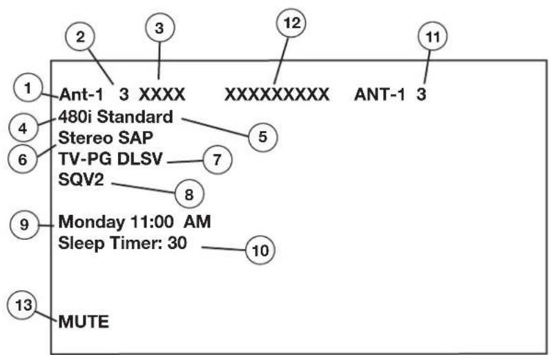
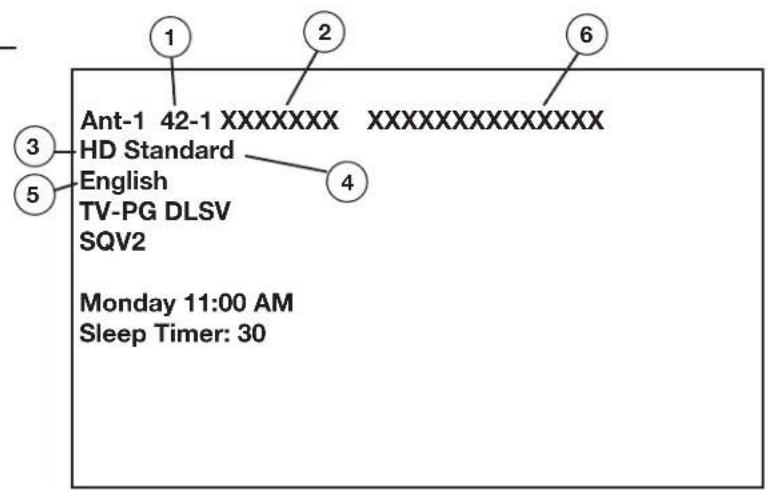
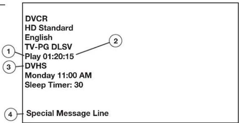
IMPORTANT
DO NOT use any kind of abrasive cleaner on the surface of the TV screen.
Cleaning
Normally, light dusting with a dry, non-scratching duster will keep your TV clean. If cleaning beyond this is needed, please use the following guidelines:
First, turn off the TV and unplug the power cord from the power outlet.
Top and Sides of the TV:
- Gently wipe down your TV with a soft, non-abrasive cloth such as cotton flannel or a clean cloth diaper, lightly moistened with water. Dry with a second dry, soft, non-abrasive cloth.
- For oily dirt, add a few drops of mild liquid detergent, such as dishwashing detergent, to the water used to moisten the cloth. Rinse with a second cloth moistened only with water. Dry with a third dry, soft, non-abrasive cloth.
Screen:
- Follow the instructions for the top and sides, however, wipe gently in an up and down motion, following the grooves in the screen.
- Clean the entire screen evenly, not just sections of the screen.
- Do not allow liquid to drip down the grooves of the screen, as some liquid may enter the TV between the screen and the screen frame.
- You may purchase Mitsubishi Screen Cleaner, part number CLEANER-VSS, by calling (800) 553-7278.
General Cleaning Warnings:
- DO NOT allow liquid to enter the TV through the ventilation slots or any crevice.
- DO NOT use any strong or abrasive cleaners as these can scratch the surfaces.
- DO NOT use any cleaners with ammonia, bleach, alcohol, benzine, or thinners as these can dull the surfaces.
- DO NOT spray liquids or cleaners directly on the TV's surfaces.
- DO NOT scrub or rub the TV harshly. Wipe it gently.
Service
If you are unable to correct a problem with your TV, consult your Mitsubishi dealer or a Mitsubishi Authorized Warranty Service Center.
- DO NOT adjust any controls other than those described in this Owner's Guide.
- DO NOT remove the protective back cover of your TV.
Menus not described and shown in this owner's guide are designed for factory use and for authorized service personnel. Damage caused to the TV by non-authorized changes or changes to these menus made by non-authorized persons are not covered under warranty.
Appendix H: Lamp Cartridge Replacement

Before you replace the lamp cartridge please note the following:
CAUTION: If the television is on, press POWER to turn it off. Allow the television to cool for one hour before attempting to replace the lamp cartridge.
LAMP LIFE
The light source for this television is a lamp, which is part of a lamp cartridge assembly. The actual life of the lamp in this television can vary, based on the lamp itself, the air temperature around the TV while it is operating, and your viewing patterns. Warmer air or poor ventilation shortens the lamp life, as does turning the television on and off frequently.
When the end of the lamp's life is approaching, the TV displays a warning message for one minute when you power on the TV. The message will reappear the next five times you turn on the TV. After you change the lamp cartridge, you must reset the lamp reminder through the TV Setup menu. Otherwise, the warning message will appear again too soon. Mitsubishi warrants the lamp for one (1) year from date of the original purchase at retail. It is likely, however, that the lamp will last significantly longer than this.
TO ORDER A NEW LAMP:
| While Under Warranty After Warranty | |
| Call (800) 332-2119. Please have model number, serial number, and TV purchase date available. | Call (800) 553-7278. Order lamp part number 915P026010. |
WARNING:
Do not remove the lamp cartridge immediately after turning off the television. You may get burned because of the lamp's high temperature. Allow the television to cool for one hour before attempting to replace the lamp cartridge.
Do not remove the lamp cartridge except when replacing it. Careless treatment can result in injury or fire.
Do not touch the lamp glass element. It may be very hot and break, causing injuries or burns.
Be sure not to insert any metal or flammable object into the lamp cartridge opening, as it may cause fire or electrical shock. If any object is inserted into the opening, unplug the AC cord of the TV and contact your dealer for service.
Install the lamp cartridge securely. Failure to do so may cause a fire.
Do not touch the lamp glass elements. Oils from your fingers may cause premature lamp failure.
The lamp in this product contains mercury. Disposal of mercury may be regulated due to environmental considerations. For disposal or recycling information, please contact your local authorities or the Electronic Industries Alliance at: www.eiae.org.
IMPORTANT
Reset the lamp hours through the TV setup menu each time you replace the lamp cartridge. Otherwise, the lamp warning message will reappear sooner than necessary.

Appendix H: Lamp Cartridge Replacement, continued

CAUTION

BURN DANGER!
During normal operation, the surfaces inside the TV near the lamp are extremely hot.
TOUCH THE LAMP CARTRIDGE BY THE HANDLE ONLY Do not touch the glass parts of the lamp cartridge.
- Turn TV power off and allow lamp to cool at least one hour before proceeding.
- Remove the plastic air exhaust grille/cover by removing two screws with a #2 (large) Phillips screwdriver. See figure 1.
- With a large flat-blade screwdriver, completely loosen the three shiny screws securing the lamp cartridge until they disengage from the mating threads. These are captive screws and cannot be removed completely from the lamp cartridge.
- Grasp the wire handle of the lamp cartridge and pull the old cartridge straight out towards you. Note the orientation of the cartridge. See figures 2 and 3.
- Do not touch the glass parts of the new lamp cartridge. Oils from your fingers on the glass could cause premature failure of the lamp. Insert the new cartridge into the TV in the same orientation as the old cartridge. Push on the cartridge housing until it is fully seated.
- With either your fingers or the screwdriver, gently tighten the three screws. If using a screwdriver, only use two fingers for final tightening. AVOID OVERTIGHTENING!
- Replace the plastic grille/cover and retaining screws.
- This lamp contains mercury. Do not dispose of old lamp with common trash. For disposal or recycling information, please contact your local authorities or the Electronic Industries Alliance at www.eiae.com.
CAUTION
ONLY REPLACE LAMP CARTRIDGE WITH THE SAME PART NUMBER 915P026010.
WARNING
THE GRILLE/COVER IS PROVIDED WITH AN INTERLOCK TO REDUCE THE RISK OF EXCESSIVE ULTRAVIOLET RADIATION. DO NOT DEFEAT ITS PURPOSE OR ATTEMPT TO SERVICE WITHOUT REMOVING GRILLE/COVER COMPLETELY.
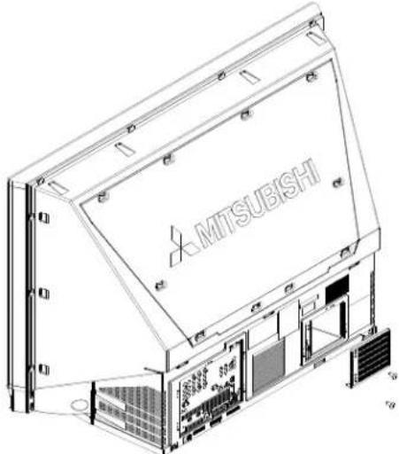
natural_image
Technical line drawing of a Mitsubishi industrial storage unit with visible internal components and mounting brackets (no text or symbols beyond branding)Figure 1. Removal of the exhaust grille
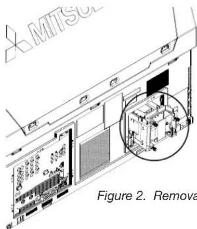
Figure 2. Removal of lamp cartridge
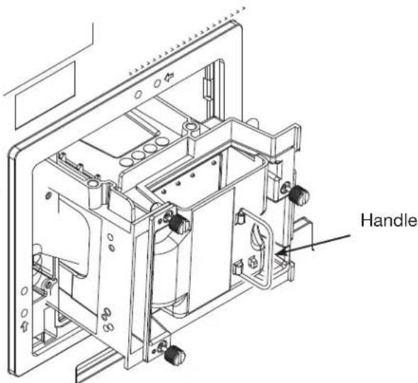
Figure 3. Lamp-cartridge handle
To order a new lamp under warranty, call (800) 332-2119. Please have model number, serial number and TV purchase date available. To order a new lamp after warranty, call (800) 553-7278 and order lamp part number 915P026010.
Trademark and License Information
LICENSOR'S SUPPLIERS DO NOT MAKE OR PASS ON TO END USER OR ANY OTHER THIRD PARTY, ANY EXPRESS, IMPLIED OR STATUTORY WARRANTY OR REPRESENTATION ON BEHALF OF SUCH SUPPLIERS, INCLUDING, BUT NOT LIMITED TO THE IMPLIED WARRANTIES OF NON-INFRINGEMENT, TITLE, MERCHANTABILITY OR FITNESS FOR A PARTICULAR PURPOSE.
CableCARD™ is a trademark of Cable Television Laboratories, Inc.
CompactFlash® and CF are trademarks of the CompactFlash Association.
DCR™ Certification Logo is a trademark of the Consumer Electronics Association.
Digital Light Processing ^™ and DLP ^™ are trademarks of Texas Instruments.
Manufactured under license from Dolby Laboratories. Dolby® and the double-D symbol are registered trademarks of Dolby Laboratories.
DTVLINK™ Certification Logo is a trademark of the Consumer Electronics Association.
Firewire® is a trademark of Apple Computer, Inc. registered in the U.S. and other countries.
HDMI™ the HDMI logo and High-Definition Multimedia Interface are trademarks or registered trademarks of HDMI Licensing LLC.
Lifestyle® 28 is a trademark of the Bose Corporation.
This product incorporates copyright protection technology that is protected by U.S. patents and other intellectual property rights. Use of this copyright protection technology must be authorized by Macrovision, and is intended for home and other limited pay-per-view uses only unless otherwise authorized by Macrovision. Reverse engineering or disassembly prohibited.

Memory Stick™ and Memory Stick PRO™ are trademarks of Sony Corp.
Microdrive® is a registered trademark of Hitachi Global Storage Technology, Inc. in the United states and/or other countries.
This product includes technology owned by Microsoft Corporation and cannot be used or distributed without a license from Microsoft Licensing, Inc.
MultiMediaCard™ is trademark of Infineon Technologies and licensed to the MultiMediaCard Association.

The PanelLink Cinema Partners logo and the “PanelLink Cinema,” “PLC” and “PLC Content Ready” word marks are trademarks of Silicon Image, Inc. and are used under a license from Silicon Image, Inc or PanelLink Cinema, LLC.
Playstation® 2 is a trademark of the Sony Corporation.

SD logo is a trademark.
SmartMedia™ is a trademark of Toshiba Corp.
In the United States, TV GUIDE and other related marks are registered marks of Gemstar-TV Guide International, Inc. and/or one of its affiliates.
The TV Guide On Screen® system is manufactured under license from Gemstar-TV Guide International, Inc. and/or one of its affiliates.
The TV Guide On Screen® system is protected by one or more of the following issued United States patents: 6,498,895; 6,418,556; 6,331,877; 6,239,794; 6,154,203; 5,940,073; 4,908,713; 4,751,578; 4,706,121.
XBox ^TM is a trademark of the Microsoft Corporation.
MonitorLink™, NetCommand®, ViewPoint®, QuickView™, SuperQuickView™, PerfectColor™, MediaCommand™, ChannelView™ are trademarks of Mitsubishi Digital Electronics America, Inc.
MITSUBISHI TV SOFTWARE
END-USER LICENSE AGREEMENT FOR EMBEDDED SOFTWARE
IMPORTANT – READ CAREFULLY: This License Agreement is a legal agreement between you (either an individual or an entity) and Mitsubishi Digital Electronics America, Inc. (MDEA) for all software pre installed and/or provided along with this television ("Software"). By utilizing this television and Software, you agree to be bound by the terms of this License Agreement.
The Software is protected by United States copyright laws and international treaty provisions, as well as other intellectual property laws and treaties. The Software is licensed, not sold.
- LICENSE GRANT. MDEA grants you a non-exclusive, non-transferable, limited right and license to use one copy of the Software only with the Mitsubishi television model that included this owner's guide and owned by you.
- RIGHTS AND LIMITATIONS.
Software Not for Resale. You may not resell or otherwise transfer for value the Software, except in conjunction with a sale of the TV that Software has been pre installed.
Prohibition on Reverse Engineering, Decompilation and Disassembly. The Software contains trade secrets or other proprietary material in its human perceivable form and to protect them, you may not reverse engineer, decompile, or disassemble, or otherwise reduce the Software to any human perceivable form, except to the extent that the foregoing restriction is expressly prohibited by applicable law.
Separation of Components. The Software is licensed as a single product. Its component parts may not be separated for use on more than one TV.
No Rental. You may not rent, lease, lend, or sublicense the Software.
Trademarks. This License Agreement does not grant you any rights to any trademarks of MDEA.
-
VIOLATIONS. You understand that any use, copying or transfer of the Software, except as permitted pursuant to this License, may subject you to serious criminal and civil penalties including damages and an award to MDEA of attorneys' fees in connection with any violation of this License. You further understand that you may be held legally responsible for any copyright infringement or other violation of intellectual property rights that is caused, encouraged, or induced by your failure to abide by the terms of the License. This license is effective until terminated, and will terminate immediately without notice from MDEA or judicial resolution if you fail to comply with any provision of this License.
-
COPYRIGHT. All title and intellectual property rights in and to the Software (including but not limited to any images, photographs, animations, video, audio, music, text, and "applets" incorporated into the Software), and any accompanying printed materials are owned by or licensed to MDEA. All title and intellectual property rights in and to the content which may be accessed through use of the Software is the property of the respective content owner and may be protected by applicable copyright or other intellectual property laws and treaties. This License Agreement grants you no rights to use such content, except that you own the media on which the Software is recorded, but MDEA and its licensors retain ownership of the Software itself. All rights not expressly granted are reserved by MDEA.
-
EXPORT RESTRICTIONS. MDEA is licensing the Software for use within the United States. You agree that you will not export or re-export the Software. You specifically agree not to export or re-export the Software: (i) to any country to which the U.S. has embargoed or restricted the export of goods or services, which currently include, but are not necessarily limited to Cuba, Iran, Iraq, Libya, North Korea, Sudan, and Syria, or to any national of any such country, wherever located, who intends to transmit or transport the Software back to such country; (ii) to any person or entity who you know or have reason to know will utilize the Software in the design, development, or production of nuclear, chemical, or biological weapons; or (iii) to any person or entity who has been prohibited from participating in U.S. export transactions by any federal agency of the U.S. government. You warrant and represent that neither the BXA nor any other U.S. federal agency has suspended, revoked, or denied your export privileges.
-
DISCLAIMER OF WARRANTY. EXCEPT AS OTHERWISE PROVIDED IN THIS LICENSE OR IN THE LIMITED WARRANTY APPLICABLE TO THE TV, MDEA MAKES NO OTHER WARRANTIES OF ANY KIND WHATSOEVER REGARDING THE SOFTWARE AND HEREBY EXPRESSLY DISCLAIMS ALL WARRANTIES OF ANY KIND WHATSOEVER, EXPRESS OR IMPLIED, WITH RESPECT TO THE SOFTWARE. ALL IMPLIED WARRANTIES, INCLUDING, WITHOUT LIMITATION, THE IMPLIED WARRANTIES OF MERCHANTABILITY AND FITNESS FOR A PARTICULAR PURPOSE ARE HEREBY EXPRESSLY DISCLAIMED BY MDEA. IN NO EVENT SHALL MDEA BE LIABLE TO YOU OR ANY THIRD PARTIES, IN CONTRACT, IN TORT OR OTHERWISE, FOR ANY DIRECT, INDIRECT, SPECIAL, INCIDENTAL OR CONSEQUENTIAL DAMAGES OF ANY KIND OR NATURE. BECAUSE SOME JURISDICTIONS DO NOT ALLOW THE EXCLUSION OR LIMITATION OF IMPLIED WARRANTIES, THE ABOVE LIMITATION MAY NOT APPLY TO YOU.
-
LIMITATION OF LIABILITY. MDEA SHALL NOT, UNDER ANY CIRCUMSTANCES BE LIABLE TO YOU OR ANY THIRD PARTIES FOR ANY DAMAGES OF ANY NATURE, WHETHER INDIRECT, SPECIAL, INCIDENTAL, CONSEQUENTIAL OR OTHERWISE, INCLUDING, BUT NOT LIMITED TO, ANY CLAIMS FOR LOST PROFITS, LOSS OF GOOD WILL OR EXPENDITURES MADE OR COMMITTED FOR IN RELIANCE ON THE CONTINUATION OF THIS LICENSE. YOU AGREE THAT NEITHER MDEA'S BREACH OF THIS LICENSE NOR ITS FAILURE TO REPAIR A DEFECT, ERROR OR BUG SHALL CONSTITUTE A FAILURE OF THE ESSENTIAL PURPOSE OF THIS LICENSE. BECAUSE SOME JURISDICTIONS DO NOT ALLOW THE EXCLUSION OR LIMITATION OF LIABILITY FOR CONSEQUENTIAL OR INCIDENTAL DAMAGES, THE ABOVE LIMITATIONS MAY NOT APPLY TO YOU. MDEA's liability to you for direct damages for any cause whatsoever and regardless of the form of the action, will be limited to the money paid by you for the TV (based on fair market value of the TV) that caused the damages.
-
GENERAL. This License Agreement will be governed by the laws of the State of California.
WARNING: This product contains chemicals known to the State of California to cause cancer and/or birth defects or other reproductive harm.
Index
A
A/V Discs 62
A/V Memory Reset. See Reset
A/V Receiver
Adding 45
Connecting 28
Inputs 45
Input Learn Screen 46
Learn Screen 46
A/V Reset. See Reset
A/V Settings Descriptions
Audio 78
Video 79,80
Accessories, TV 10
Add Device. See NetCommand
Advanced Learn Screen, [Device] 50
Antenna inputs (ANT-1 MAIN, ANT-2 AUX) 16
Antenna with Leads 25
Audio/Video Menu 64, 77
Audio Inputs 16
B
Back Panel, illustrated 16
Batteries. See Remote Control
C
CableCARD™ 11, 17, 23
Cable Box 54, 104
Connecting 24, 27
Captions Menu 64, 72
CD. See A/V Discs
Change Device Screen. See NetCommand
Channels 66, 70, 107. See also SQV
and PIP viewing 82
Changing 70
Memorizing 65
Name 70
ChannelView 59
Channel Menu 70
Cleaning and Service 108
Clock. See Time, Set
Color Adjustments 79
Component Inputs (YPbPr) 16
Computer. See PC
Connecting: Helpful Hints 35
Connecting External Devices 22
Connection for [Device] Screen 50
Connection Screen 56
Copy-Protected Material 62
D
Date, set 66
Day, set 66
Daylight Savings Time 66
Demo Mode 19
Device Menu 58
Device Selection Menu 57
Digital Audio Output 17
Display Formats 83
DTV Link 17
DVD. See A/V Discs
DVD Player with Component Video 29
DVI Analog Audio 16
DVI Device 29
F
Front Button Lock 76
Front Control Panel 12
G
GUIDE Key (button) 12, 14, 35, 59
H
HDMI Device 30
HDMI Input 17
HDTV Receiver with Component Video 30
|
Icon Order 67
IEEE 1394
Adding IEEE 1394 Devices Automatically 55
and NetCommand 54
Compatible IEEE 1394 Devices 33
Connecting IEEE 1394 Devices 33
IEEE 1394 Device Type Screen 56
Inputs 17
Name for 1394 Device Screen 55
New 1394 Device Screen 55
Indicator Lights 90
Front Panel 12
Lamp Indicator 13
Power/Timer 12
Status 13
Inputs (Audio/Video) 16
IR (Infrared)
IR Code for [Device] Screen 51
IR Emitter NetCommand® 16, 32
J
JPEG Picture Thumbnails (Media Dialog Box) 87
L
Lamp Cartridge Replacement 109
Lamp Indicator. See Indicator Lights
Lamp Reminder 66
Language 65
"Learn" Feature
A/V Receiver 45, 46
Code Reference Chart 101
Description 22, 38, 39
Device 49, 50
Device Key Reference Chart 106
GUIDE Key 35
IEEE 1394 Devices 56
Troubleshooting 90, 91
Learn Screen, [Device] 49
M
Media Cards 11
Media Card Slots 18
Media Setup Menu 88
Playback 87
Memorize Channels. See Channels
Memory Card Slots 18, 87
Mute
Audio 72, 107
MUTE key 14
Video Mute 77
N
Name Screen 47, 50
NetCommand
Add Device 48
Change Device 52
Connecting External Devices 22
Delete Device 52
Description 11
Device Control, reference chart 104
Device Setup Screen 43
Edit NetCommand Screen 48
Initial Setup 42
NetCommand Menu 67
Pre-Memorized Devices 39
Specialized Device Keys 106
0
On-Screen Information 107
P
PC 16, 17, 48, 55, 83
Connecting
DVI Monitor Output 31
HDMI Monitor Output 31
Viewing 85
Peer-to-Peer Connection 61
PIP (Picture in Picture) 82
PIP Device Selection Menu 57
Playlist Menu, MP3 or WMA7 88
Power Devices On/Off 57
Q
QV (QuickView™) 14
R
Recording
Recording Now 60, 68
Record To List 59
Record To Menu 59
Record To Setup 60, 68
Time-Delayed 60, 68
VCR Recording from an Antenna or Cable Source 62
Recordings
Cancel Current Recordings 61, 69
Record List Screen 61, 69
Remote Control
and NetCommand® 39
Batteries 15
Functions 14
Programming 101
Programming Codes (reference chart) 101
Transport Buttons 67
Reset
A/V (all settings) 12
A/V Memory (for individual devices) 77
DVCR Counter 105
Lamp Reminder 66
PerfectColor 79
Remote Control 15
Reset Menu 19
System Reset Button 12, 19, 91
VCR Counter 104
Review Screen 44
RF Connection for Cable Screen 51
S
S-Video 28
Satellite Receiver 28
Search A/V Disc. See A/V Discs
Setup Menu 64, 65
Signal and Format Definitions 83
Speakers, TV 77
Specifications, TV 99
SQV (SuperQuickView™) 71
Status Indicator. See Indicator Lights
Stereo. See A/V Receiver
T
Time, Set 65, 66
Timer 66
Time Zone 66
Track List Screen 62
Transport Menu 67
Troubleshooting 90
TV Guide On Screen 11, 14, 16, 24, 61, 69
Setup 43
V
V-Chip 74, 75
Bypassing the V-Chip Lock 97
Definitions 75
Entry 74
Lock TV by Time 76
V-Chip Lock Menu 64, 74
VCR
Connecting 26, 27
Restrictions for Traditional VCRs 62
VCR for Recordings Screen 51
Video Inputs 16
Video Settings 79
W
Wall Outlet Cable 22, 24
Mitsubishi DLP™ Projection Television Limited Warranty
MITSUBISHI DIGITAL ELECTRONICS AMERICA, INC. ("MDEA") warrants as follows to the original purchaser of this television from an authorized MITSUBISHI Audio/Video Dealer, should it prove defective by reason of against defects arising from improper workmanship and/or material:
a. Parts. The lenticular (i.e. front picture) screen is warranted against defects in materials and workmanship for a period of thirty (30) days from the date of the original purchase at retail. The lamp and all other parts (except any software incorporated into this television) are warranted for a period of one (1) year from the date of the original purchase at retail. We will repair or replace, at our option, any defective part without charge for the part. Parts used for replacement may be replaced with those of like kind and quality and may be new or remanufactured. Parts used for replacement are warranted for the remainder of the original warranty period.
b. Embedded Software. MDEA warrants that all software incorporated into this television set (the "Embedded Software") will perform in accordance with the functional description of Embedded Software in all material respects, but MDEA does not warrant that the Embedded Software is error-free. MDEA also does not warrant that the Embedded Software will be compatible under IEEE 1394 AV/C and HAVi software standards with products produced by any other manufacturer. The limited warranty contained in this section shall continue for a period of one (1) year from the date of the original purchase at retail. If, after prompt notice within the warranty period, MDEA determines that the Embedded Software has failed to perform in accordance with such functional description in all material respects and if such failure is not due to accident, misuse, modification or misapplication of the Embedded Software, then MDEA shall modify or replace the nonconforming Embedded Software at no charge to you, which at MDEA's sole discretion may be fulfilled by means of modification or replacement software contained on a replacement memory card for Customer installation. The foregoing shall be MDEA's sole obligation to you under this limited warranty. All rights under this limited warranty on the Embedded Software also subject to your acceptance of and compliance with the terms of the Software License Agreement applicable to this television, and this limited warranty on the Embedded Software shall be null and void if the Embedded Software is modified or changed in any manner except as specifically authorized by MDEA.
c. Labor. For thirty (30) days after the original purchase at retail, we will repair or replace, at our option, the lenticular screen if it proves defective. For certain items that are designed to be replaced by the consumer, including (but not limited to) some Embedded Software, the consumer is solely responsible for any replacement labor. For all other parts, we will provide the labor for a warranty repair by an authorized MITSUBISHI service center without charge for one (1) year from the original date of purchase at retail.
d. Notice. To obtain warranty service, you must notify an authorized MITSUBISHI service center of any defect within the applicable warranty time period.
e. This DLP Projection Television uses a single DLP chip to create the screen image. This technology creates the image using small dots, or picture elements (pixels). Your DLP Projection TV is manufactured to a high level of performance and quality, in fact, 99.99% perfect in the number of properly functioning pixels. As in other display technology, sometimes a pixel is continuously active, inactive or the incorrect color. Our standard is clear; MDEA warrants only that the percentage of properly functioning pixels will be not less than 99.99% of all pixels.
BEFORE REQUESTING SERVICE, please review the instruction booklet to insure proper installation and correct customer control adjustment. If the problem persists please arrange for warranty service.
- TO OBTAIN WARRANTY SERVICE:
a. Contact your nearest authorized MITSUBISHI service center, whose name and address can be obtained from your MITSUBISHI dealer, by writing at the address provided below, calling MDEA at the 800-332-2119, or by using the support feature of our website at www.Mitsubishi-tv.com.
b. Warranty service will be provided in your home or, if required, at an authorized service shop, provided that your television is located within the geographic territory customarily covered by an authorized MITSUBISHI service center. If not, you must either deliver your television to an authorized service location at your own expense, or pay for any travel and/or transportation costs the service center may charge to and from your home. Actual service labor will be provided without charge.
c. Proof of purchase date from an authorized MITSUBISHI dealer is required when requesting warranty service. Present your sales receipt or other document which establishes proof and date of purchase. THE RETURN OF THE OWNER REGISTRATION CARD IS NOT A CONDITION OF COVERAGE UNDER THIS LIMITED WARRANTY. However, please return the Owner Registration Card so that we can contact you should a question of safety arise which could affect you.
d. To obtain a replacement lamp during the warranty period, please contact the MDEA Consumer Relations Department at (800) 332-2119. After the warranty period you may order the lamp directly from the MDEA Parts Department at (800) 553-7278.
- THIS LIMITED WARRANTY DOES NOT COVER:
a. Up to .01% pixel outages (small dot picture elements that are dark or incorrectly illuminated).
b. Damage to the lenticular screen or Fresnel lens, screen frame, cosmetic damage or to any other damage where such damage is caused by unauthorized modification, alteration, repairs to or service of the product by anyone other than an authorized MITSUBISHI service center; physical abuse to or misuse of the product (including any failure to carry out any maintenance as described in the Owner's Guide including air filter cleaning or any product damaged by excessive physical or electrical stress); any products that have had a serial number or any part thereof altered, defaced or removed; product use in any manner contrary to the Owner's Guide; freight damage; or any damage caused by acts of God or other factors beyond the reasonable control of MDEA, such as power surge damage caused by electrical system or lightning. This limited warranty also excludes service calls where no defect in the product covered under this warranty is found, service calls related to unsatisfactory audio or visual reception or signal unless caused by a defect in the product that is covered under this limited warranty, all costs, expenses or any other damages arising from product installation, or set-ups, any adjustments of user controls (including contrast, brightness, color, tint, fine tuning, sharpness), other adjustment necessary to prepare the unit for display or use, connection with any external audio receiver, antenna, cable or satellite systems, or service of products purchased or serviced outside the U.S.A. Please consult the operating instructions contained in the Owner's Guide furnished with the product for information regarding user controls.
-
ANY EXPRESS WARRANTY NOT PROVIDED HEREIN, AND ANY REMEDY WHICH, BUT FOR THIS PROVISION, MIGHT ARISE BY IMPLICATION OR OPERATION OF LAW, IS HEREBY EXCLUDED AND DISCLAIMED. THE IMPLIED WARRANTIES OF MERCHANTABILITY AND OF FITNESS FOR ANY PARTICULAR PURPOSE ARE EXPRESSLY LIMITED TO A TERM OF ONE YEAR.
-
UNDER NO CIRCUMSTANCES SHALL MDEA BE LIABLE TO PURCHASER OR ANY OTHER PERSON FOR ANY INCIDENTAL, SPECIAL OR CONSEQUENTIAL DAMAGES, WHETHER ARISING OUT OF BREACH OF WARRANTY, BREACH OF CONTRACT, OR OTHERWISE.
-
Some states do not allow limitations on how long an implied warranty lasts, or the exclusion or limitation of incidental, special, or consequential damages, so the above limitations or exclusions may not apply to you.
-
This limited warranty gives you specific legal rights, and you may also have other rights which vary from state to state.

MITSUBISHI
MITSUBISHI DIGITAL ELECTRONICS AMERICA, INC.
9351 Jeronimo Road
Irvine, CA 92618-1904
Website:
www.mitsubishi-tv.com
E-mail:
MDEAservice@mdea.com
To order replacement or additional remote controls, lamp cartridges or Owner's Guides, call 800-553-7278
For questions, call Consumer Relations at 800-332-2119
- Projection Television Models
- WD-52627, WD-62627
- Owner's Guide
- CAUTION
- Custom cabinet installation must allow for proper air circulation around the television.
- TV Guide On Screen® Access Requirements
- Stand Requirement
- Lamp Replacement
- FCC Declaration of Conformity
- IMPORTANT SAFEGUARDS
- Read, Retain and Follow All Instructions
- Heed Warnings
- Cleaning
- Attachments and Equipment
- Water and Moisture
- Accessories
- Ventilation
- Power Source
- Grounding or Polarization
- Power-Cord Protection
- Lightning
- IMPORTANT SAFEGUARDS, continued
- Power Lines
- Overloading
- Object and Liquid Entry
- Outdoor Antenna Grounding
- Servicing
- Damage Requiring Service
- Replacement Parts
- Safety Check
- Heat
- Contents
- Chapter 1: Television Overview
- Chapter 2: Connecting
- Chapter 3: NetCommand® Setup and Editing
- Chapter 4: IEEE 1394 Devices and NetCommand®-Controlled Recordings
- Chapter 5: TV Menu Screen Operations
- Chapter 6: Additional Features
- Chapter 7: Troubleshooting 89
- Appendices
- Trademark and License Information 111
- Index 113
- Mitsubishi DLP™ Projection Television Limited Warranty 115
- Our Thanks...
- Chapter ...
- Television Overview
- TV Accessories
- Special Features
- High Definition DLP™ Display System
- TV Guide On Screen® Interactive Program Guide System
- Digital Cable Ready (CableCARD™)
- NetCommand® Home Network Control System
- 16:9 Widescreen Picture Format
- Media Cards
- Front Control Panel
- System Reset
- A/V Reset
- Front-Panel Indicator Lights
- Front Control Panel, continued
- Remote Control
- Overview
- Remote Control, continued
- Battery Installation
- Figure 2 Installing the Batteries:
- Care
- For Best Results from the Remote Control:
- Sleep Timer
- Setting the Sleep Timer:
- Cancelling the Sleep Timer:
- TV Back Panel
- Antenna (ANT-1 MAIN, ANT-2 AUX)
- IR EMITTER NetCommand®
- INPUT 1 and 2
- (Audio/Video 1 and 2)
- COMPONENT 1, 2, and 3 Inputs YPbPr (480i/480p/720p/1080i)
- DVI Analog Audio
- AUDIO OUTPUT, RECORD OUTPUT
- TV Back Panel, continued
- HDMI TM 1 and 2
- HDMI 2
- DTV Link™/IEEE 1394
- CableCARD™ Slot
- Digital Audio Output
- Media Card Slots and Front-Panel Inputs
- Media Card Slots
- Front-Panel Input 3
- IMPORTANT
- Additional Information
- Using the System Reset Button
- Using the Reset Menu to Reset the TV
- Read on-screen warnings before proceeding, as some user data or settings may be erased.
- Demo Mode
- Connecting
- Connecting External Devices and NetCommand® Setup
- CableCARD™ Technology
- CableCARD Technology
- Using a CableCARD
- Connecting a Wall Outlet Cable or Cable Box
- Wall Outlet Cable
- Standard Cable Box
- Connecting an Antenna with a Single Lead or Antennas with Separate UHF and VHF Leads
- Antenna with a Single Lead
- For antennas with flat twin leads
- For cable or antenna with coaxial lead
- Antennas with Separate UHF and VHF Leads
- Connecting a VCR to an Antenna or Wall Outlet Cable Connecting VCR Audio and Video to the TV
- VCR to an Antenna or Wall Outlet Cable (Audio & Video)
- Note:
- Connecting a VCR to a Cable Box (Audio & Video)
- VCR to a Cable Box (Audio & Video)
- Connecting an A/V Receiver (Stereo System) Connecting a Satellite Receiver or Other Device with S -Video
- A/V Receiver (Stereo System)
- To connect an analog A/V receiver:
- To connect a digital A/V receiver with Dolby® Digital surround sound:
- Satellite Receiver or Other Device with S-Video
- Connecting a DVD Player with Component Video Connecting a DVI Device
- DVD Player with Component Video
- DVI Device
- Connecting an HDTV Cable Box or Satellite Receiver with Component Video Connecting an HDMI Device
- HDTV Cable Box or Satellite Receiver with Component Video
- HDMI Device
- Connecting a Computer with an HDMI or DVI Monitor Output
- Computer with an HDMI Monitor Output
- Computer with a DVI Monitor Output
- Connecting the IR Emitter NetCommand®
- IR Emitter NetCommand®
- Connecting Compatible IEEE 1394 Devices
- Compatible IEEE 1394 Devices
- Digital Video Signals
- Digital Audio Signals
- Digital Control Signal
- When Connecting IEEE 1394 Devices
- Connecting Compatible IEEE 1394 Devices, continued
- Connection Styles
- Direct Device-To-Device Style
- Hub Connection Style
- 4-Pin Style vs. 6-Pin Style Connectors
- Helpful Hints
- NetCommand® Setup and Editing
- NetCommand® Introduction
- Welcome To NetCommand
- NetCommand makes your TV the heart of your Home Theater
- IR Learning and IEEE 1394 Support
- Using NetCommand is completely optional
- NetCommand and Levels of Control
- - Basic Setup
- - Limited Setup
- - Full Setup
- NetCommand Helps You Manage Your Home Theater
- Using the Remote Control with NetCommand®
- NetCommand® Setup On-Screen Buttons
- Text Box
- Check Box
- Radio Buttons
- Control Buttons
- Cancel Button
- ▶ViewPoint™ Menu Screens
- ▶ViewPoint Remote Control Buttons
- NetCommand® Initial Setup
- Welcome Screen
- Figure 1
- NetCommand (Information) Screen
- Figure 2
- Setup Reminder
- Figure 3
- NetCommand® Initial Setup, continued
- Device Setup Screen
- Figure 4
- TV Guide On Screen® System Setup
- Figure 5
- Review Screen
- Finish Screen
- Edit NetCommand®: Add an A/V Receiver
- A/V Receiver Screen
- Figure 8
- A/V Receiver Inputs
- Figure 9
- Edit NetCommand®: Add an A/V Receiver, continued
- A/V Receiver (AVR) Input Learn Screen
- A/V Receiver (AVR) Learn Screen
- Name Screen
- Figure 12
- Figure 14
- Audio Output to AVR Screen
- Figure 13
- Edit NetCommand®: Add Devices
- Edit NetCommand Screen
- Figure 15
- Add:
- Change:
- Guide:
- Review:
- Delete:
- Initial:
- Add Screen
- Figure 16
- Edit NetCommand®: Add Devices, continued
- [Device] Screen
- [Device] Learn Screen
- [Device] Advanced Learn Screen
- Figure 19
- Figure 20
- Connection for [Device] Screen
- Figure 21
- VCR for Recordings Screen
- Figure 22
- RF Connection for Cable Screen
- Figure 23
- IR Code for [Device] Screen
- Figure 24
- Edit NetCommand®: Change or Delete Devices
- Change Device Screen
- Figure 25
- Delete Device Screen
- Figure 26
- Figure 27
- IEEE 1394 Devices and NetCommand®-Controlled Recordings
- IEEE 1394 Devices and NetCommand® Control
- NetCommand Control of Digital Devices Using the "Learn" Feature.
- Adding IEEE 1394 Devices Automatically
- New 1394 Device Screen
- Name for 1394 Device Screen
- Adding IEEE 1394 Devices Automatically, continued
- IEEE 1394 Device Type Screen
- Connection Screen
- Device Selection Menu
- Power On/Off Devices
- Device Section
- Video Section
- Connection Section
- Audio Section
- PIP Device Selection Menu
- Using the Device Menu Button to Display Menus
- Device Menu
- IR Controlled Devices
- Moving Through Other CableCARD Screens
- CableCARD™ Menu
- Using the GUIDE Button to Display ChannelView™ and Menus
- The GUIDE Button
- GUIDE and Devices (1394 or IR Controlled)
- GUIDE and the Device Selection Menu
- GUIDE and the Record To Menu
- GUIDE and ChannelView
- Recording a Current Program
- Recording Future Programs
- NetCommand®-Controlled Recordings
- Setting up Recordings
- Recording Now
- Time-Delayed Recording
- Record List, Peer-to-Peer Connections
- Record List
- TV Guide On Screen® and the Record List
- Cancel Current Recordings
- Peer-to-Peer Connections
- Setting up a Peer-to-Peer Connection
- Canceling a Peer-to-Peer Connection
- Using A/V Discs Direct VCR Recording from an Antenna or Cable Source Copy-Protected Material and Restrictions for Traditional VCRs
- Using A/V Discs
- A/V Disc Search
- Track List Screen
- Using the Remote Control with an A/V Disc after selecting from the Device Selection menu:
- Direct VCR Recording from an Antenna or Cable Source:
- Copy-Protected Material
- Restrictions for Traditional VCRs
- TV Menu Screen Operations
- Main Menu
- Setup Menu
- NetCommand Menu
- Record Menu
- Channel Menu
- Captions Menu
- V-Chip Lock Menu
- Figure 6
- Audio/Video Menu
- Figure 7
- Language
- Memorize Channels
- For Antenna 1 (Main) or Antenna 2 (Aux)
- Clock
- Manual
- Time
- Setup Menu, continued
- Date
- Time Zone
- Daylight Savings Time
- Auto
- Timer On/Off
- Figure 10
- Set Day
- Set Time
- Device
- Channel
- Lamp Reminder
- Software Version
- NetCommand® Menu
- Edit
- Icon Order
- Transport Menu
- Remote Control Transport Buttons
- Record
- Recording Setup
- Record Menu, continued
- Default Digital (Record) Device
- Analog Recordings
- Setting Up Analog Recordings with TV Guide On Screen®
- Antenna
- Prefer Digital
- Memory
- Name
- Channel Menu, continued
- SQV (SuperQuickView™)
- Adding SQV Channels
- Removing SQV Channels
- Adding SQV channels using the remote control:
- Removing SQV channels using the remote control:
- Signal Strength
- Figure 18
- Analog Captions
- Background
- Digital Captions
- Appearance
- Digital Settings
- Captions Menu, continued
- Fonts
- Size
- Color
- Opacity (Font)
- Background Opacity
- V-Chip
- Entry
- V-Chip Start Time and V-Chip Stop Time
- V-Chip Lock Menu: V-Chip Definitions
- V-Chip Signal Information
- V-CHIP EXCEPTIONS:
- Content Categories:
- Movie Ratings:
- V-Chip Lock Menu, continued
- Lock By Time
- Front Button Lock
- Audio/Video
- A/V Memory Reset
- Settings
- Video Mute
- Film Mode
- TV Speakers
- Using the AUDIO or VIDEO Button on the Remote Control
- A/V Setting Descriptions: Audio
- Analog and Digital Audio Settings
- ◇ Bass
- Treble
- Balance
- ◇ Surround
- ◇ Level Sound
- Analog-Only Audio Settings
- ◇ Listen to
- Digital-Only Audio Settings
- ◇ Language
- IEEE 1394 Amplifier Settings
- ◇ Loudness
- ◇ Preset
- ◇ Equalizer
- A/V Setting Descriptions: Video
- Video Settings
- Bright/Natural Modes
- A/V Setting Descriptions: Video, continued
- Auto Position
- ◇ HorizPosition (Horizontal Position)
- ◇ VertPosition (Vertical Position)
- ◇ Fine Detail
- Additional Features
- Operation of PIP
- Changing PIP Device
- Changing PIP/Side-by-Side Channels
- Exchanging Program Images
- Moving PIP Image
- Freezing the PIP and Side-by-Side Pictures
- TV Display Formats
- DVD Definitions:
- Non-Anamorphic (or 4:3, 1:33:1, Letter box or Full Screen):
- Signal and Format Definitions:
- PC Viewing
- PC Display Formats
- MediaCommand™ and Media Card Playback
- Inserting a media card
- Remote Control Buttons for Controlling the Playback
- For JPEG Pictures Slide show:
- For MP3 or WMA Audio Playback
- Using the Picture Thumbnail Menu or Audio Play list Menu
- For JPEG Picture Thumbnail Menu:
- Media Command™ and Media Card Playback, continued
- For MP3 or WMA7 Play list Menu:
- COMPATIBLE PICTURE OR AUDIO FILES:
- For JPEG Pictures up to 1 GB:
- For MP3 or WMA7 Audio files:
- Media Setup Menu
- For JPEG Picture Slide show Setup
- For MP3 or WMA7 Audio Play list Setup
- Troubleshooting
- Appendix A: Bypassing the V-Chip Lock
- Bypassing the V-Chip Lock
- Bypassing Front Button Lock
- Appendix C: Remote Control Programming Codes
- Programming the Remote to Control NetCommand A/V Products
- Programming the Remote to Control Other Brands of Audio and Video Products
- Appendix C: Remote Control Programming Codes, continued
- TV position:
- Cable/SAT/DTV position:
- VCR position:
- DVD position:
- Audio position:
- VCR
- Cable Boxes and Satellite Receivers
- A/V Receivers
- Mitsubishi A/V Receivers
- Mitsubishi CD Players
- (not all functions for all models)
- DVD and Laser Disc Players
- Appendix F: On-Screen Information Displays
- Analog Program
- Possible:
- Digital Program
- Digital IEEE 1394 Device
- Cleaning
- Top and Sides of the TV:
- Screen:
- General Cleaning Warnings:
- Service
- Appendix H: Lamp Cartridge Replacement
- CAUTION: If the television is on, press POWER to turn it off. Allow the television to cool for one hour before attempting to replace the lamp cartridge.
- LAMP LIFE
- WARNING:
- Appendix H: Lamp Cartridge Replacement, continued
- BURN DANGER!
- WARNING
- Trademark and License Information
- MITSUBISHI TV SOFTWARE
- END-USER LICENSE AGREEMENT FOR EMBEDDED SOFTWARE
- Index
- A
- B
- C
- D
- F
- G
- H
- |
- J
- L
- M
- N
- 0
- P
- Q
- R
- S
- T
- V
- W
- Mitsubishi DLP™ Projection Television Limited Warranty
- MITSUBISHI
Brand : MITSUBISHI
Model : WD-52627
Category : TV