4C Coupe (2015) - Car ALFA ROMEO - Free user manual and instructions
Find the device manual for free 4C Coupe (2015) ALFA ROMEO in PDF.

User questions about 4C Coupe (2015) ALFA ROMEO
0 question about this device. Answer the ones you know or ask your own.
Ask a new question about this device
Download the instructions for your Car in PDF format for free! Find your manual 4C Coupe (2015) - ALFA ROMEO and take your electronic device back in hand. On this page are published all the documents necessary for the use of your device. 4C Coupe (2015) by ALFA ROMEO.
USER MANUAL 4C Coupe (2015) ALFA ROMEO
4C
2015
OWNER'S MANUAL
VEHICLESSOLDINCANADA
WithrespecttoanyVehiclesSoldinCanada,thenameFCA USLLCshallbedeemedtobedeletedandthenameFCA CanadaInc. usedinsubstitutiontherefore.
DRIVINGANDALCOHOL
Drunkendrivingisoneofthemostfrequentcausesof accidents.
Yourdrivingabilitycanbeseriouslyimpairedwithblood alcohollevelsfarbelowthelegalminimum.Ifyouare drinking,don'tdrive.Ridewithadesignatednon-drinkingdriver,callacab,afriend,orusepublictransportation.
WARNING!
Drivingafterdrinkingcanleadtoanaccident. Yourperceptionsarelesssharp,yourreflexesare slower,andyourjudgmentisimpairedwhenyou havebeendrinking.Neverdrinkandthendrive.
Thismanualillustratesanddescribestheoperationof featuresandequipmentthatareeitherstandardorop-tionalonthisvehicle. Thismanualmayalsoincludea descriptionoffeaturesandequipmentthatarenolonger availableorwerenotorderedonthisvehicle.Please disregardanyfeaturesandequipmentdescribedinthis manualthatarenotonthisvehicle.
FCAUSLLCreservestherighttomakechangesindesign andspecifications, and/ormakeadditionstoorimprovementstoitsproductswithoutimposinganyobligation uponitselftoinstallthemonproductspreviouslymanufactured.
Copyright©2016FCAUSLLC

SECTIONPAGE
TABLEOFCONTENTS
1 INTRODUCTION....3
2 THINGSTOKNOWBEFORESTARTINGYOURVEHICLE. 9
3 UNDERSTANDINGTHEFEATURESOFYOURVEHICLE. 71
4 UNDERSTANDINGYOURINSTRUMENTPANEL....109
5 STARTING AND OPERATING ....
6 WHAT TODO INEMERGENCIES....
7 MAINTAINING YOUR VEHICLE....
8 MAINTENANCESCHEDULES. 305
9 IF YOU NEED CONSUMER ASSISTANCE 315
10 INDEX
INTRODUCTION
CONTENTS
■INTRODUCTION....4
■HOW TO USE THIS MANUAL....4
■WARNINGS AND CAUTIONS....6
■VEHICLE IDENTIFICATION NUMBER....6
■VEHICLE MODIFICATIONS/ALTERATIONS....7
4INTRODUCTION
INTRODUCTION
Congratulations on selecting your new vehicle. Be assured that it represents precision workmanship, distinctive styling, and high quality - all essentials that are traditional to our vehicles.
This Owner's Manual has been prepared with the assistance of service and engineering specialists to acquaint you with the operation and maintenance of your vehicle. It is supplemented by Warranty Information, and various customer-oriented documents. Please take the time to read these publications carefully. Following the instructions and recommendations in this manual will help assure safe and enjoyable operation of your vehicle.
The enclosed Warranty Information lists the services that FIAT Group Automobiles offers to its customers:
- The Warranty Certificate with terms and conditions for maintaining its validity
- The range of additional services available to FIAT Group Automobiles customers
NOTE: After reviewing the owner information, it should bestored in the vehicle for convenient referencing and remain with the vehicle when sold.
When it comes to service, remember that your authorized dealer knows your vehicle best, has factory-trained technicians and genuine parts, and cares about your satisfaction.
HOWTOUSETHISMANUAL
Consult the Table of Contents to determine which section contains the information you desire.
Since the specification of your vehicle depends on the items of equipment ordered, certain descriptions and illustrations may differ from your vehicle's equipment.
The detailed index at the back of this Owner's Manual contains a complete listing of all subjects.
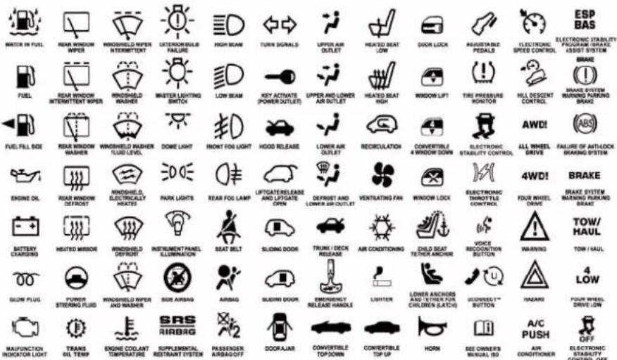
Consult the following table for a description of the symbols that may be used on your vehicle or throughout this Owner's Manual:
010533317
6INTRODUCTION
WARNINGSANDCAUTIONS
This Owners Manual contains WARNINGS against operating procedures that could result in a collision or bodily injury. It also contains CAUTIONS against procedures that could result in damage to your vehicle. If you do not read this entire Owners Manual, you may miss important information. Observe all Warnings and Cautions.
VEHICLEIDENTIFICATIONNUMBER
The Vehicle Identification Number (VIN) is found on the left front corner of the instrument panel, visible through the windshield. This number also appears engraved on an Aluminum plate glued and riveted on the floor crossmember under the passenger seat.
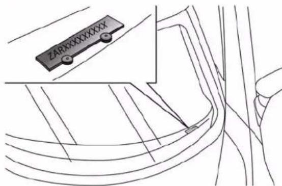
VehicleIdentificationNumber
NOTE: It is illegal to remove or alter the VIN.
VEHICLEMODIFICATIONS/ALTERATIONS
WARNING!
Anymodificationsoralterationstothisvehiclecould seriouslyaffectitsroadworthinessandsafetyandmay leadtoacollisionresultinginseriousinjuryordeath.
THINGSTOKNOWBEFORESTARTINGYOURVEHICLE
CONTENTS
■A WORD ABOUT YOUR KEYS....11
□Ignition Key Removal....1 2
□Locking Doors With A Key ..... 1 3
□Key-In-Ignition Reminder....14
■SENTRY KEY®....14
□Replacement Keys....15
□General Information....15
■VEHICLE SECURITY ALARM SYSTEM — IF EQUIPPED....15
□To Arm The System....16
□To Disarm The System....17
■ILLUMINATED ENTRY ..... 1 7
■REMOTE KEYLESS ENTRY (RKE) — IF EQUIPPED....18
□To Unlock The Doors....19
□To Lock The Doors....19
□Transmitter Battery Replacement....20
□General Information....2 1
■DOOR LOCKS 2 2
□Central Door Locking/Unlocking....2 2
□Locking/Unlocking Doors From The Inside . . .23
□Emergency Door Locking Device....24
□Door Opening/Closing Mechanism Reset ..... 2 5
■WINDOWS....25
□Power Windows....25
■DECKLID....28
■OCCUPANT RESTRAINT SYSTEMS ..... 3 0
□Seat Belt Systems....32
□Supplemental Restraint System (SRS)....42
□Child Restraints....56
■ENGINE BREAK-IN RECOMMENDATIONS....66
■SAFETY TIPS....67
□Transporting Passengers....67
□Exhaust Gas 68
□Safety Checks You Should Make Inside The Vehicle....69
☐Periodic Safety Checks You Should Make Outside The Vehicle....70
THINGSTOKNOWBEFORESTARTINGYOURVEHICLE11
AWORDABOUTYOURKEYS
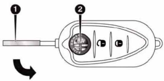
The key fob contains the Remote Keyless Entry (RKE) transmitter with an integrated key. To use the mechanical key simply push the mechanical key release button.

KeyFob
1 — Vehicle Key
2 — Push To Open/Close Vehicle Key
12THINGSTOKNOWBEFORESTARTINGYOURVEHICLE IgnitionKeyRemoval
- Push the brake pedal and place the transmission into first (1) or reverse (R) gear by selecting/pushing the buttons on the console.
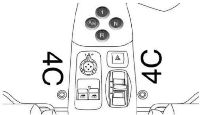
TransmissionGearSelector
-
Rotate the key to the STOP (OFF/LOCK) position and engage the handbrake and release brake pedal.
-
Remove the key from the ignition switch lock cylinder.
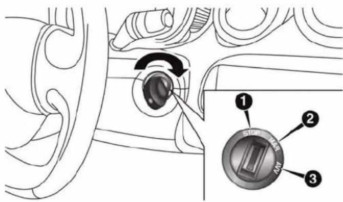
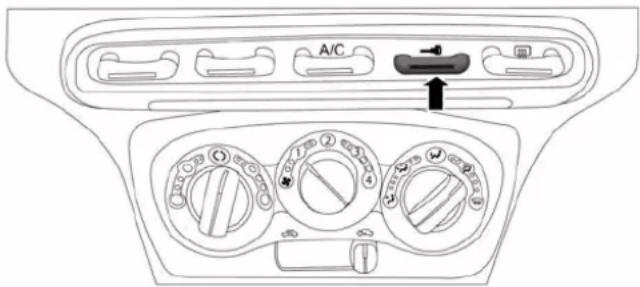
IgnitionSwitchPositions
1 — STOP (OFF/LOCK)
2 — MAR (ACC/ON/RUN)
3—AVV (START)
THINGSTOKNOWBEFORESTARTINGYOURVEHICLE13
WARNING!
- Beforeexitingthevehicle,alwaysapplytheparkingbrake,andremovetheKeyFobfromthe ignition.Whenleavingthevehicle,alwayslock yourvehicle.
- Neverleavechildrenaloneinavehicle,orwith accesstoanunlockedvehicle.
- Allowingchildrentobeinavehicleunattendedis dangerousforanumberofreasons.Achildorothers couldbeseriouslyorfatallyinjured.Children shouldbewarnednottotouchtheparkingbrake, brakepedalorthetransmissiongearselector.
- DonotleavetheKeyFobinornearthevehicle, or inalocationaccessibletochildren. Achildcould operatepowerwindows, othercontrols, ormove thevehicle.
WARNING!(Continued)
- Donotleavechildrenoranimalsinsideparked vehiclesinhotweather.Interiorheatbuild-upmay causeseriousinjuryordeath.
CAUTION!
An unlocked carisan invitation to thieves. Always removethe key from the ignition and lock all the doors when leaving the vehicle unattended.
LockingDoorsWithAKey
You can insert the key with either side up. To lock the door, turn the key to the left. To unlock the door, turn the key to the right. Refer to "Body Lubrication" in "Maintaining Your Vehicle" for maintenance information.
(Continued)
Opening the driver's door when the key is in the ignition and the ignition switch position is OFF/LOCK, sounds a signal to remove the key.
SENTRYKEY®
The Sentry Key® Immobilizer System prevents unauthorized vehicle operation by disabling the engine. The system does not need to be armed or activated. Operation is automatic, regardless of whether the vehicle is locked or unlocked.
The system uses ignition keys which have an embedded electronic chip (transponder) to prevent unauthorized vehicle operation. Therefore, only keys that are programmed to the vehicle can be used to start and operate the vehicle.
NOTE:A key which has not been programmed is also considered an invalid key, even if it is cut to fit the ignition switch lock cylinder for that vehicle.
If the Vehicle Security Light is on after the key is turned to the ON/RUN position, it indicates that there is a problem with the electronics.
CAUTION!
- AlwaysremovetheSentryKey®fromthevehicle andlockalldoorswhenleavingthevehicleunattended.
- The SentryKey® Immobilizersystemisnotcompatiblewithsomeaftermarketremotestartingsystems.Useofthesesystemsmayresultinvehicle startingproblemsandlossofsecurityprotection.
All of the keys provided with your new vehicle have been programmed to the vehicle electronics.
ReplacementKeys
NOTE: Only keys that have been programmed to the vehicle electronics can be used to start the vehicle. Once a Sentry Key® has been programmed to a vehicle, it cannot be programmed to any other vehicle.
NOTE: When having the Sentry Key® Immobilizer Systems serviced, bring all vehicle keys with you to an authorized dealer.
GeneralInformation
The Sentry Key® system complies with FCC rules part 15 and with RSS-210 of Industry Canada. Operation is subject to the following conditions:
- This device may not cause harmful interference.
- This device must accept any interference that may be received, including interference that may cause undesired operation.
THINGSTOKNOWBEFORESTARTINGYOURVEHICLE 15
NOTE: Changes or modifications not expressly approved by the party responsible for compliance could void the user's authority to operate the equipment.
VEHICLESECURITYALARMSYSTEM—IF EQUIPPED
The Vehicle Security Alarm monitors the doors and decklid for unauthorized entry. It will also activate the siren and emit a visual flash of the turn signals (front and rear) for any of the following intrusion cases.
Operation
The alarm activates in the following cases:
- Wrongful opening of one of the doors or the decklid (perimeter protection);
- Cutting of the battery leads;
- Movement inside the passenger compartment (volumetric protection);
- Anomalous lifting/tilting of the vehicle.
Operation of the alarm is indicated by a visual signal (flashing of the direction indicators for several seconds). There is a maximum number of visual cycles. When this is reached the system returns to normal operation.
ToArmTheSystem
With the doors and decklid closed and the ignition key either turned to STOP (OFF/LOCK) or removed, point the key towards the vehicle then push and release the lock button.
The system emits a visual signal and activates door locking.
A self-diagnosis stage lasting approximately 30 seconds precedes the activation of the alarm. During the self-diagnosis, the vehicle security light flashes in the instrument panel at a frequency of about one flash per second.
After the self-diagnosis stage, the vehicle security light flashes at a lower frequency (approximately one flash every three seconds).
If, after the alarm is switched on, a second visual signal emit via the vehicle security light in the instrument panel, wait about four seconds and switch off the alarm by pushing the lock button, check that the doors and decklid are closed correctly and then reactivate the system by pushing the unlock button.
If the alarm emits a visual signal even when the doors and decklid are closed correctly, a system malfunction has occurred: in this case, contact a authorized vehicle Dealership.
THINGSTOKNOWBEFORESTARTINGYOURVEHICLE17
ToDisarmTheSystem
Deactivation
Push the unlock button.
The following operations are performed:
- Two brief flashes of the direction indicators.
- Unlocking of the doors.
NOTE:
- If the central door locking system is released using the metal insert of the key, the alarm is not disabled.
- In the event of accidental activation of the alarm, or in any case to interrupt the visual signal cycle when activated, it is possible to push the unlock button or turn the ignition key to MAR (ON/RUN) for at least five seconds, after which the system will deactivate.
Disarming
To completely disable the alarm (e.g. during a lengthy period of vehicle inactivity), lock the vehicle by turning the metal insert of the key in the door lock.
NOTE: If the batteries of the key fob run out or there is a fault in the system, the alarm can be switched off by inserting the key in the ignition switch and turning it to MAR (ON/RUN).
ILLUMINATEDENTRY
The interior lights will turn on whenever a door is opened and the dimmer switch is not in the defeat position.
The interior lights will turn on, remain on for approximately 30 seconds, and then fade to off if a door is opened using the outside door handle and then closed or a door is unlocked using the vehicles key.
The interior lights will turn on and remain on for about four seconds and then fade to off if a door is opened using the inside door handle.
NOTE: None of the courtesy lights will operate if the dimmer control is in the "defeat" position (extreme downward position), unless the overhead map/reading lights are turned on manually.
REMOTEKEYLESSENTRY(RKE)—IF EQUIPPED
This system allows you to lock or unlock the doors and decklid from distances up to approximately 66 ft (20 m) using a hand-held Remote Keyless Entry (RKE) transmitter. The RKE transmitter does not need to be pointed at the vehicle to activate the system.
KeyFob
1 — Vehicle Key
2 — Push To Open/Close Vehicle Key
NOTE: The line of transmission must not be blocked with metal objects.
ToUnlockTheDoors
Push and release the UNLOCK button on the RKE transmitter to unlock the doors. The park lights and turn signal lights will flash to acknowledge the signal and the illuminated entry system will turn on.
NOTE: The Door Unlock Indicator will illuminate in the instrument panel when one or both doors are unlocked.
ToLockTheDoors
Push and release the LOCK button on the RKE transmitter: locking of doors, switching off of internal roof light and single flashing of direction indicators.
If one or more door are open, the doors will not be locked. This is indicated by a rapid flashing of the direction indicators. The doors will be locked if the decklid is open however.
When a speed of more than 12 mph (20 km/h) is reached, the doors will be locked automatically if the Autoclose
THINGSTOKNOWBEFORESTARTINGYOURVEHICLE19
function was selected. Refer to “Electronic Vehicle Information Center (EVIC)” in “Understanding Your Instrument Panel” for further information.
When the doors are locked from outside the car (using the remote control), the door lock indicator will illuminate for a few seconds and then start flashing (deterrent function).
DoorLEDLockIndicator
20THINGSTOKNOWBEFORESTARTINGYOURVEHICLE TransmitterBatteryReplacement
NOTE: Perchlorate Material – special handling may apply. See www.dtsc.ca.gov/hazardouswaste/perchlorate The recommended replacement battery is CR2032.
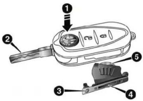
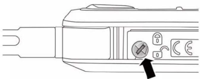
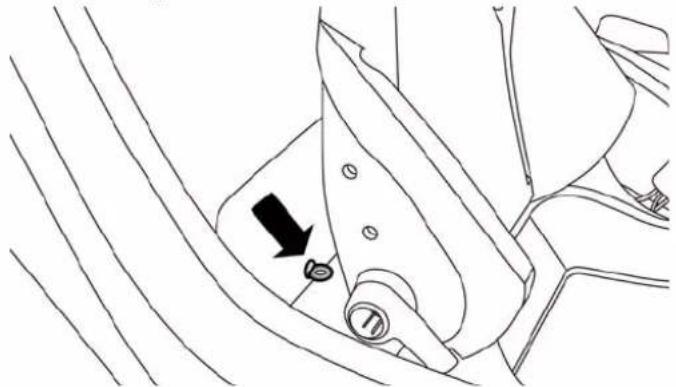
BatteryReplacementProcedure
Replace the Key Fob battery with the following procedure:
- Push button #1 and move the metal insert #2 to opening position;
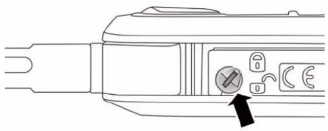
- Turn screw #3 to unlock using a fine bit screwdriver;
natural_image
Line drawing of a plug connector with a switch and padlock, showing internal components (no text or symbols)KeyFobScrewLocation
-
Remove battery compartment #4;
-
Replace battery #5, respecting the polarity;
- Reinsert compartment #4 in the key and secure it by turning screw #3 to lock.
natural_image
Line drawing of a plug connector with a switch and three buttons, no text or symbols presentKeyFobScrewLocation
THINGSTOKNOWBEFORESTARTINGYOURVEHICLE21
GeneralInformation
This device complies with Part 15 of the FCC rules and RSS 210 of Industry Canada. Operation is subject to the following conditions:
• This device may not cause harmful interference.
- This device must accept any interference received, including interference that may cause undesired operation.
NOTE: Changes or modifications not expressly approved by the party responsible for compliance could void the user's authority to operate the equipment.
If your RKE transmitter fails to operate from a normal distance, check for these two conditions:
- A weak battery in the transmitter. The expected life of the battery is a minimum of three years.
- Closeness to a radio transmitter such as a radio station tower, airport transmitter, and some mobile or CB radios.
DOORLOCKS
CentralDoorLocking/Unlocking
LockingDoorsFromTheOutside
With the doors closed, push the lock button on the key fob or turn the metal insert (located inside the key fob) in the door lock.
The Door Lock LED Indicator button → will illuminate to indicate that the doors have locked.
DoorLockLEDIndicator
NOTE: Door locking is carried out with all doors shut.
UnlockingDoorsFromTheOutside
Push the unlock button on the key or turn the metal insert (located inside the key) in the driver side door lock.
THINGSTOKNOWBEFORESTARTINGYOURVEHICLE23
WARNING!
- Forpersonalsecurityandsafetyintheeventofacollision,lockthevehicledoorsbeforeyoudriveaswellaswhenyouparkandleavethevehicle.
- Neverleavechildrenaloneinavehicle,orwith accesstoan unlocked vehicle. Allowingchildrento beinavehicleunattendedisdangerousfora numberofreasons.Achildorotherscouldbe seriouslyorfatallyinjured.Childrenshouldbe warnednottotouchtheparkingbrake,brakepedal orthetransmissiongearselector.
- DonotleavetheKeyFobinornethevehicle, or inalocationaccessibletochildren. Achildcould operatepowerwindows, othercontrols, ormove thevehicle.
Locking/UnlockingDoorsFromThelinside
Push the Lock LED Indicator button →. The button has an LED that indicates whether the doors are locked or unlocked.
Pushing the Lock LED Indicator button → again centrally unlocks all doors and switches off the LED.
Pushing the Lock LED Indicator button → again centrally locks all the doors. The doors will be locked only if all the doors are properly shut.
Once the doors have been locked using the remote control or the key, it will no longer be possible to unlock them by pushing the Lock LED Indicator button →.
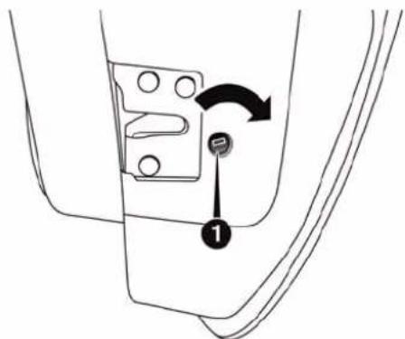
NOTE: In the absence of electrical power supply (blown fuse, battery disconnected, etc.) it is still possible to lock the doors manually.
The passenger side door has a device to lock it when there is no current.
To lock it, place the metal insert of the ignition key in housing #1 and turn it clockwise.
EmergencyDoorLockFunction
To restore the starting condition of the door locks (only if battery charge restored), proceed as follows:
- Push the Unlock button on the remote control;
-
Push the door locking/unlocking LED indicator button → on the dashboard; or
-
Introduce the metal insert of the ignition key in the front door pawl; or
- Pull the internal door handle.
DoorOpening/ClosingMechanismReset
If the battery is disconnected or the protection fuse blows, the door opening/closing mechanism must be reset as follows:
- Close all the doors.
- Push the unlock button on the key or the door locking/unlocking LED indicator button → on the dashboard.
THINGSTOKNOWBEFORESTARTINGYOURVEHICLE25
- Push the lock button on the key or the door locking/unlocking LED indicator button → on the dashboard.
WINDOWS
PowerWindows
NOTE:
- These operate when the ignition key is turned to MAR-ON and for about three minutes after the ignition key is turned to STOP or removed unless one of the doors is opened.
- The buttons are located on the center console.
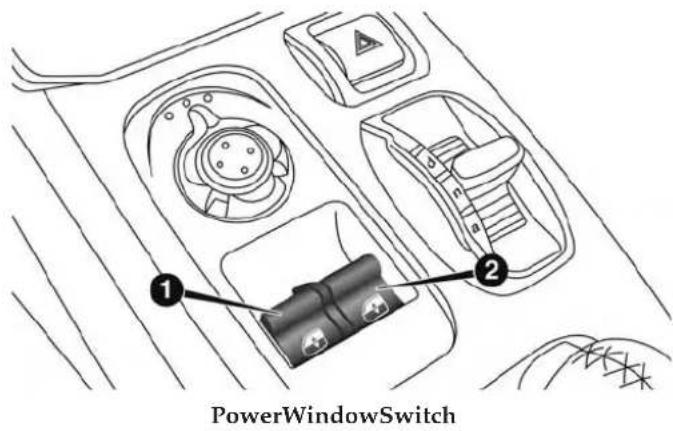
1 — Driver Power Window Switch
2 — Passenger Power Window Switch
Push the corresponding buttons to open/close the desired window.
When one of the two buttons is pushed briefly, the window moves in stages; if the button is held down to open, "continuous automatic" operation is activated.
If the button is pushed again the window will stop in its current position. If the button is pushed for several seconds, the window lowers automatically (only with ignition key in MAR-ON position).
ContinuousAutomaticOperation
This is activated by pushing one of the two buttons for longer than half a second. The window will stop when it is fully opened, or when the button is pushed again.
It can be used on both the driver side and passenger side, only for lowering the window.
ElectricWindowSystemReset
After a break in power supply for the control units (battery replaced or disconnected or protective fuses for the electric window control units replaced), the automatic operation of the windows must be restored.
The restoration procedure must be performed as described below with the doors closed:
- Completely open the driver's door window keeping the operating button pushed for at least three seconds after the (lower) end of travel position is reached.
- Completely raise the driver side window and hold the button down for at least three seconds once the (upper) end of travel position has been reached.
- Proceed in the same way as described in points 1 and 2 for the passenger side door.
THINGSTOKNOWBEFORESTARTINGYOURVEHICLE27
- Make sure that the reset is correct by checking that the windows work automatically.
WARNING!
Improperactuationofthepowerwindowsmaybe dangerous.Neverleavechildrenunattendedina vehicle,andonotletchildrenplaywithpower windows.Beforeandduringwindowoperation makesurenooneandnoobject(includingclothing) isinthepathofthemovingglassoritsmechanism. Donotleavethekeyfobinornethevehicle,orinalocationaccessibletochildren.Occupants,particularlyunattendedchildren,canbecomeentrappedby thewindowswhileoperatingthepowerwindow switches.Suchentrapmentmayresultinserious injuryordeath.
NOTE: During normal car operation, the luggage compartment can reach temperatures above 149^ F ( 65^ C). Pay attention when transporting objects that may be damaged at such temperatures. Do not keep aerosol cans in the car: danger of explosion. Aerosol cans must not be exposed to temperatures above 122^ F ( 50^ C).
OpeningProcedure
With driver side door open, pull lever #1 located at the point illustrated in the figure.
DecklidReleaseLeverLocation
1 — Decklid Release Lever
Raise the decklid and release supporting rod from its locking device.
Insert the end of the rod in housing, making sure that the rod engages in the smallest hole of the retaining clip. Care must be taken to keep the decklid raised until the rod is fixed in the correct position.
NOTE: Maintain a tight grip on the decklid when raising, in order to prevent any external occurrence (e.g. a gust of wind) from suddenly opening the decklid to end of travel. Additionally, in order to prevent any damage to the car or broken windows, do not force the decklid beyond the opening position necessary to secure the supporting rod in the hole of the retaining clip.
ClosingProcedure
- Hold the decklid up with one hand and use the other to remove rod from housing and reinsert it in its locking device.
- Lower the decklid approximately 7.8 inches (20 cm) from the engine compartment and let it drop. Make
THINGSTOKNOWBEFORESTARTINGYOURVEHICLE29
sure that the decklid is completely closed and not only fastened in safety position by trying to open it. If it is not completely closed, do not push the decklid down, but raise it and repeat the procedure.
NOTE: Always check that the decklid is closed correctly to prevent it from opening while the car is travelling.
WARNING!
- Themaximumpermittedloadintheluggagecompartment, in addition to the kits provided, is 33.1lbs.(15kg). Donot exceed them a maximum permitted loadintheluggage compartment.
- When accessing therear luggage compartment, donot come into contact with engine, or other components, that may be hot and could burn you if touched.
- Accesstheluggagecompartmentonlywiththe vehiclestationary.Beforeexitingavehicle,you
(Continued)
WARNING!(Continued)
shouldalwaysshiftthevehicleintogear,remove thekeyfobfromtheignition,andapplythe parkingbraketosecurethevehicleagainstunwantedmovement.
- Thedecklidmaydropsuddenly, causing serious injury, if the supporting drodis not positioned correctly.
- Thedecklidmustalwaysbeclosedproperly,and thelockengaged,whilethecarisinmotion.
OCCUPANTRESTRAINTSYSTEMS
Some of the most important safety features in your vehicle are the restraint systems:
- Seat Belt Systems
• Supplemental Restraint Systems (SRS) Air Bags
- Child Restraints
ImportantSafetyPrecautions:
Please pay close attention to the information in this section. It tells you how to use your restraint system properly, to keep you and your passenger as safe as possible.
Here are some simple steps you can take to minimize the risk of harm from a deploying air bag:
-
Children 12 years old and under should always ride buckled up in a vehicle with a rear seat.
-
If a child from 2 to 12 years old (not in a rear-facing child restraint) must ride in the front passenger seat, move the seat as far back as possible and use the proper child restraint. (Refer to "Child Restraints").
-
Children that are not big enough to wear the vehicle seat belt properly (Refer to "Child Restraints") should be secured in a vehicle with a rear seat in child
restraints or belt-positioning booster seats. Older children who do not use child restraints or belt-positioning booster seats should ride properly buckled up in a vehicle with a rear seat.
- Never allow children to slide the shoulder belt behind them or under their arm.
- You should read the instructions provided with your child restraint to make sure that you are using it properly.
- All occupants should always wear their lap and shoulder belts properly.
- The driver and front passenger seats should be moved back as far as practical to allow the Advanced Front Air Bags room to inflate.
- Do not lean against the door or window. If your vehicle has side air bags, and deployment occurs, the
THINGSTOKNOWBEFORESTARTINGYOURVEHICLE31
side air bags will inflate forcefully into the space between you and the door and you could be injured.
- If the air bag system in this vehicle needs to be modified to accommodate a disabled person, contact the Customer Center. Phone numbers are provided under "If You Need Assistance."
WARNING!
- Neverplacearear-facingchildrestraintinfrontof anairbag.AdeployingPassengerAdvancedFront AirBagcancausedeathorseriousinjurytoachild 12yearsoryounger,includingachildinarear-facingchildrestraint.
- Onlyuserear-facingchildrestraintinvehicle witharearseat.
Buckle up even though you are an excellent driver, even on short trips. Someone on the road may be a poor driver and could cause a collision that includes you. This can happen far away from home or on your own street.
Research has shown that seat belts save lives, and they can reduce the seriousness of injuries in a collision. Some of the worst injuries happen when people are thrown from the vehicle. Seat belts reduce the possibility of ejection and the risk of injury caused by striking the inside of the vehicle. Everyone in a motor vehicle should be belted at all times.
EnhancedSeatBeltUseReminderSystem (BeltAlert)
The Belt Alert feature is active whenever the ignition switch is in the START or ON/RUN position. In this condition if the driver is unbelted, a continuous chime
signal will start for few seconds and the Seat Belt Reminder Light will turn on until the driver seat belt is buckled.
If the driver seat belt is unbuckled once the vehicle speed is over 12.5 mph (20 km/h) or when travelling at a speed from 6 to 12.5 mph (10 to 20 km/h) for few seconds, the BeltAlert® warning sequence begins by blinking the Seat Belt Reminder Light and sounding an intermittent chime. Once the sequence starts, it will continue for the entire duration or until the driver's seat belt is buckled. After the sequence completes, the Seat Belt Reminder Light remains illuminated until the driver's seat belt is buckled. The driver should instruct all other occupants to buckle their seat belts.
It is recommended that pets be restrained in the rear seat (if equipped) in pet harnesses or pet carriers that are secured by seat belts, and cargo is properly stowed.
THINGSTOKNOWBEFORESTARTINGYOURVEHICLE33
BeltAlert can be activated or deactivated by your authorized dealer. FCA US LLC does not recommend deactivating BeltAlert.
NOTE: If BeltAlert has been deactivated, the Seat Belt Reminder Light will continue to illuminate while the driver's seat belt remains unbuckled and a continuous chime will sound when the ignition switch is first placed in the START or ON/RUN position.
Lap/ShoulderBelts
All seating positions in your vehicle are equipped with lap/shoulder belts.
The seat belt webbing retractor will lock only during very sudden stops or collisions. This feature allows the shoulder part of the seat belt to move freely with you under normal conditions. However, in a collision the seat belt will lock and reduce your risk of striking the inside of the vehicle or being thrown out of the vehicle.
This seat belt system has a retractor assembly that is designed to release webbing in a controlled manner. This feature is designed to help reduce the seat belt force acting on the occupant's chest.
WARNING!
- Relyingontheairbagsalonecouldleadtomore severeinjuriesinacollision.Theairbagsworkwith yourseatbelttorestrainyouproperly.Insomecollisions,theairbagswon'tdeployatall.Alwayswear yourseatbelteventhoughyouhaveairbags.
- Inacollision, you and your passengers can suffer much greater injuries if you are not properly buckled up. You can strik the interior of your vehicle or other passengers, or you can be thrown out of the vehicle. Always besure you and others in your vehicle are buckled up properly.
(Continued)
- Itisdangeroustorideinacargoarea, insideor outsideofavehicle. Inacollision, peopleriding in theseareasaremorelikelytobeseriouslyinjured orkilled.
- Donotallowpeopletorideinanyareaofyourvehicle thatisnotequippedwithseatsandseatbelts.
- Besureeveryoneinyourvehicleisinaseatand usingaseatbeltproperly.
- Wearingyourseatbeltincorrectlycouldmakeyour injuriesinacollisionmuchworse.Youmight sufferinternalinjuries,oryoucouldevenslideout oftheseatbelt.Followtheseinstructionstowear yourseatbeltsafelyandtokeepyourpassengers safe,too.
- Twopeopleshouldneverbebeltedintoasingle seatbelt.Peoplebeltedtogethercancrashintoone
WARNING!(Continued)
anotherinacollision, hurtingoneanotherbadly. Neverusealap/shoulderbeltoralapbeltformore thanoneperson,nomatterwhattheirsize.
- Alapbeltworntoohighcanincreasetheriskof injuryinacollision.Theseatbeltforceswon'tbeat thestronghipandpelvicbones,butacrossyour abdomen.Alwayswearthelappartofyourseat beltaslowaspossibleandkeepitsnug.
- Atwistedseatbeltmaynotprotectyouproperly.In acollision, itcouldevencutintoyou.Besurethe seatbeltisflatagainstyourbody, withouttwists.If youcan'tstraightenaseatbeltinyourvehicle, take ittoyourauthorizeddealerimmediately and have itfixed.
- Aseatbeltthatisbuckledintothewrongbuckle willnotprotectyouproperly. Thelapportioncould
(Continued)
(Continued)
THINGSTOKNOWBEFORESTARTINGYOURVEHICLE35
WARNING!(Continued)
ridetoohighonyourbody,possiblycausinginternalinjuries.Alwaysbuckleyourseatbeltintothe bucklenearestyou.
- Aseatbeltthatistooloosewillnotprotectyou properly.Inasuddenstop,youcouldmovetoofar forward,increasingthepossibilityofinjury.Wear yourseatbeltsnugly.
- Aseatbeltthatiswornunderyourarmisdangerous. Yourbodycouldstriketheinsidesurfacesofthe vehicleinacollision,increasingheadandneckinjury. Aseatbeltwornunderthearmcancauseinternal injuries.Ribsaren'tasstrongassshoulderbones.Wear theseatbeltoveryourshouldersothatyourstrongest boneswilltaketheforceinacollision.
- Ashoulderbeltplacedbehindyouwillnotprotect youfrominjuryduringacollision.Youaremore
(Continued)
WARNING!(Continued)
likelytohityourheadinacollisionifyoudonot wearyourshoulderbelt. Thelapandshoulderbelt aremeanttobeusedtogether.
- Afrayedortornseatbeltcould dripapartina collision and leave you with no protection. Inspect these seat belts system periodically, checking for cuts, frays, or loose parts. Damaged part must be placed immediately. Donot disassemble or modify these seat belts system. Seat belt assemblies must be replaced after a collision.
Lap/ShoulderBeltOperatingInstructions
- Enter the vehicle and close the door. Sit back and adjust the seat.
- The seat belt latch plate is above the back of the front seat, and next to your arm in the rear seat (for vehicles equipped with a rear seat). Grasp the latch plate and
pull out the seat belt. Slide the latch plate up the webbing as far as necessary to allow the seat belt to go around your lap.
natural_image
Diagram of a car seatbelt buckle assembly showing belt and seat alignment (no text or labels)PullingOutTheLatchPlate
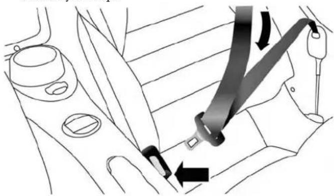
- When the seat belt is long enough to fit, insert the latch plate into the buckle until you hear a "click."
natural_image
Diagram of a car seatbelt buckle being inserted into the seat, showing no text or symbolsInsertingLatchPlateIntoBuckle
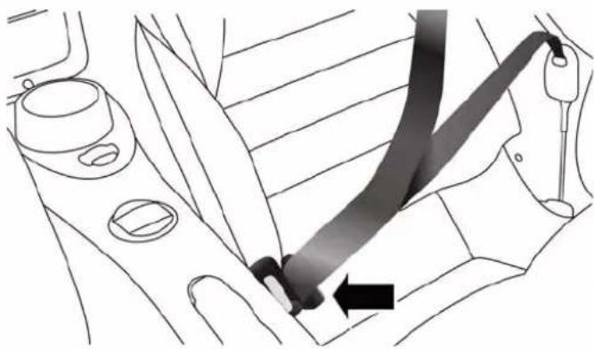
- Position the lap seat belt so that it is snug and lies low across your hips, below your abdomen. To remove slack in the lap belt portion, pull up on the shoulder belt. To loosen the lap belt if it is too tight, tilt the latch plate and pull on the lap belt. A snug seat belt reduces the risk of sliding under the seat belt in a collision.
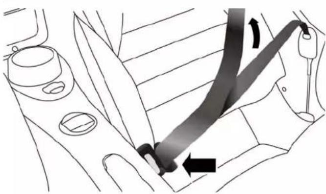
natural_image
Diagram of a car seatbelt mechanism showing left and right side views with motion arrows (no text or symbols)PositioningTheLapBelt
-
Position the shoulder belt across the shoulder and chest with minimal, if any slack so that it is comfortable and not resting on your neck. The retractor will withdraw any slack in the shoulder belt.
-
To release the seat belt, push the red button on the buckle. The seat belt will automatically retract to its
THINGSTOKNOWBEFORESTARTINGYOURVEHICLE37
stowed position. If necessary, slide the latch plate down the webbing to allow the seat belt to retract fully.
Lap/ShoulderBeltUntwistingProcedure
Use the following procedure to untwist a twisted lap/shoulder belt.
- Position the latch plate as close as possible to the anchor point.
- At about 6 to 12 in (15 to 30 cm) above the latch plate, grasp and twist the seat belt webbing 180 degrees to create a fold that begins immediately above the latch plate.
- Slide the latch plate upward over the folded webbing. The folded webbing must enter the slot at the top of the latch plate.
- Continue to slide the latch plate up until it clears the folded webbing and the seat belt is no longer twisted.
SeatBeltsAndPregnantWomen
We recommend that pregnant women use the seat belts throughout their pregnancy. Keeping the mother safe is the best way to keep the baby safe.
Pregnant women should wear the lap portion of the seat belt across the thighs and as snug across the hips as possible. Keep the seat belt low so that it does not come across the abdomen. That way the strong bones of the hips will take the force if there is a collision.
SeatBeltPretensioner
The front seat belt system is equipped with pretensioning devices that are designed to remove slack from the seat belt in the event of a collision. These devices may improve the performance of the seat belt by removing slack from the seat belt early in a collision. Pretensioners work for all size occupants, including those in child restraints.
NOTE: These devices are not a substitute for proper seat belt placement by the occupant. The seat belt still must be worn snugly and positioned properly.
The pretensioners are triggered by the Occupant Restraint Controller (ORC). Like the air bags, the pretensioners are single use items. A deployed pretensioner or a deployed air bag must be replaced immediately.
EnergyManagementFeature
This vehicle has a seat belt system with an Energy Management feature in the front seating positions that may help further reduce the risk of injury in the event of a collision. This seat belt system has a retractor assembly that is designed to release webbing in a controlled manner.
AutomaticLockingRetractorMode(ALR)
The seat belt in the passenger seating position is equipped with a switchable Automatic Locking Retractor (ALR) which is used to secure a child restraint system. For additional information, refer to "Child Restraints" in "Things To Know Before Starting Your Vehicle." The image below defines the type of feature for each seating position.
THINGSTOKNOWBEFORESTARTINGYOURVEHICLE39
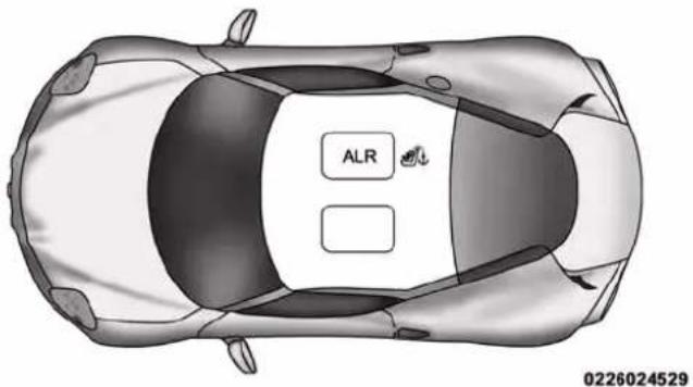
- ALR = Switchable Automatic Locking Retractor
• Top Tether Anchorage Symbol
If the passenger seating position is equipped with an ALR and is being used for normal usage:
Only pull the seat belt webbing out far enough to comfortably wrap around the occupant's mid-section so as to not activate the ALR. If the ALR is activated, you will hear a clicking sound as the seat belt retracts.
Allow the webbing to retract completely in this case and then carefully pull out only the amount of webbing necessary to comfortably wrap around the occupant's mid-section. Slide the latch plate into the buckle until you hear a "click."
In Automatic Locking Mode, the shoulder belt is automatically prelocked. The seat belt will still retract to remove any slack in the shoulder belt. The Automatic Locking Mode is available on all passenger-seating positions with a combination lap/shoulder belt.
Use the Automatic Locking Mode anytime a child restraint is installed in a seating position that has a seat belt with this feature. Children 12 years old and under should always be properly restrained in a vehicle with a rear seat.
WARNING!
- Neverplacearear-facingchildrestraintinfrontof anairbag.AdeployingPassengerAdvancedFront AirBagcancausedeathorseriousinjurytoachild 12yearsoryounger,includingachildinarear-facingchildrestraint.
- Onlyuserear-facingchildrestraintinvehicle witharearseat.
HowToEngageTheAutomaticLockingMode
- Buckle the combination lap and shoulder belt.
- Grasp the shoulder portion and pull downward until the entire seat belt is extracted.
THINGSTOKNOWBEFORESTARTINGYOURVEHICLE41
- Allow the seat belt to retract. As the seat belt retracts, you will hear a clicking sound. This indicates the seat belt is now in the Automatic Locking Mode.
HowToDisengageTheAutomaticLockingMode
Unbuckle the combination lap/shoulder belt and allow it to retract completely to disengage the Automatic Locking Mode and activate the vehicle sensitive (emergency) locking mode.
WARNING!
- TheseatbeltassemblymustbereplacediftheswitchableAutomaticLockingRetractor(ALR)featureor anyotherseatbeltfunctionisnotworkingproperly whencheckedaccordingtotheproceduresinthe ServiceManual.
- Failuretoreplacetheseatbeltassemblycould increasetheriskofinjuryincollisions.
- DonotusetheAutomaticLockingModetorestrain occupantswhoarewearingtheseatbeltorchildren whoareusingboosterseats. Thelockedmodeis onlyusedtoinstallrear-facingorforward-facing childrestraintsthathaveaharnessforrestraining thechild.
SupplementalRestraintSystem(SRS)
AirBagSystemComponents
Your vehicle may be equipped with the following air bag system components:
•Occupant Restraint Controller (ORC)
• Air Bag Warning Light
•Steering Wheel and Column
- Instrument Panel
- Knee Impact Bolsters
- Advanced Front Air Bags
• Supplemental Side Air Bags
• Supplemental Driver Knee Air Bag
- Front and Side Impact Sensors
- Front Seat Belt Pretensioners, Seat Belt Buckle Switch, and Seat Track Position Sensors
AdvancedFrontAirBags
This vehicle has Advanced Front Air Bags for both the driver and front passenger as a supplement to the seat belt restraint systems. The driver's Advanced Front Air Bag is mounted in the center of the steering wheel. The passenger's Advanced Front Air Bag is mounted in the instrument panel. The words AIRBAG are embossed on the air bag covers.
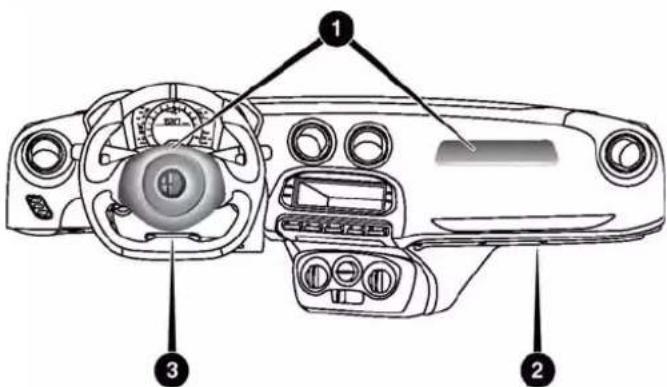
AdvancedFrontAirBagLocations
1 — Driver And Passenger Advanced Front Air Bags
2 — Passenger Knee Bolsters
3 — Supplemental Driver Knee Air Bag/Driver Knee Bolster
THINGSTOKNOWBEFORESTARTINGYOURVEHICLE43
WARNING!
- Beingtooclosetothesteeringwheelorinstrument panelduringAdvancedFrontAirBagdeployment couldcauseseriousinjury,includingdeath.Air bagsneedroomtoinflate.Sitback,comfortably extendingyourarmstoreachthesteeringwheelor instrumentpanel.
- Neverplacearear-facingchildrestraintinfrontof anairbag.AdeployingPassengerAdvancedFront AirBagcancausedeathorseriousinjurytoachild 12yearsoryounger,includingachildinarear-facingchildrestraint.
- Onlyusearear-facingchildrestraintinvehicle witharearseat.
AdvancedFrontAirBagFeatures
The Advanced Front Air Bag system has multistage driver and front passenger air bags. This system provides
output appropriate to the severity and type of collision as determined by the Occupant Restraint Controller (ORC), which may receive information from the front impact sensors or other system components.
The first stage inflator is triggered immediately during an impact that requires air bag deployment. A low energy output is used in less severe collisions. A higher energy output is used for more severe collisions.
This vehicle may be equipped with driver and/or front passenger seat track position sensors that may adjust the inflation rate of the Advanced Front Air Bags based upon seat position.
This vehicle may be equipped with a driver and/or front passenger seat belt buckle switch that detects whether the driver or front passenger seat belt is fastened. The seat belt buckle switch may adjust the inflation rate of the Advanced Front Air Bags.
WARNING!
- Noobjectsshouldbeplacedoverorneartheair bagontheinstrumentpanel, becauseanysuch objectscouldcauseharmifthevehicleisina collisionsevereenoughtocausetheairbagto inflate.
- Donotputanythingonoraroundtheairbag coversorattempttoopenthemmanually.Youmay damagetheairbagsandyoucouldbeinjured becausetheairbagsmaynolongerbefunctional. Theprotectivecoversfortheairbagcushionsare designedtoopenonlywhentheairbagsare inflating.
- Relyingontheairbagsalonecouldleadtomore severeinjuriesinacollision.Theairbagswork withyourseatbelttorestrainyouproperly.In
(Continued)
WARNING!(Continued)
somecollisions, airbags won't deploy at all. Always we are your seat belt seventh though you have air bags.
AdvancedFrontAirBagOperation
Advanced Front Air Bags are designed to provide additional protection by supplementing the seat belts. Advanced Front Air Bags are not expected to reduce the risk of injury in rear, side, or rollover collisions. The Advanced Front Air Bags will not deploy in all frontal collisions, including some that may produce substantial vehicle damage — for example, some pole collisions, truck underrides, and angle offset collisions.
On the other hand, depending on the type and location of impact, Advanced Front Air Bags may deploy in crashes with little vehicle front-end damage but that produce a
THINGS TO KNOW BEFORE STARTING YOUR VEHICLE
severe initial deceleration. Because air bag sensors measure vehicle deceleration over time, vehicle speed and damage by themselves are not good indicators of whether or not an air bag should have deployed.
Seat belts are necessary for your protection in all collisions, and also are needed to help keep you in position, away from an inflating air bag.
When the ORC detects a collision requiring the Advanced Front Air Bags, it signals the inflator units. A large quantity of non-toxic gas is generated to inflate the Advanced Front Air Bags.
The steering wheel hub trim cover and the upper right side of the instrument panel separate and fold out of the way as the air bags inflate to their full size. The Advanced Front Air Bags fully inflate in less time than it takes to blink your eyes. The air bags then quickly deflate while helping to restrain the driver and front passenger.
This vehicle is equipped with Supplemental Door-Integrated Side Air Bag Inflatable Curtains (SABICs).
SABICs may help reduce the risk of head injury to front seat outboard occupants in certain side impacts. SABICs may reduce the risk of injuries in certain side impacts, in addition to the injury reduction potential provided by the seat belts and body structure. The SABICs are located in the door trim below the side windows. The trim covering the SABICs is labeled AIRBAG.
The SABICs may help reduce the risk of partial or complete ejection of vehicle occupants through side windows in certain side impact events.
The SABICs deploy upward, covering the side windows. An inflating SABIC pushes the outside edge of the trim out of the way and covers the window. The SABICs inflate with enough force to injure you if you are not belted and seated properly, or if items are positioned in the area where the SABICs inflate. Children are at an even greater risk of injury from a deploying air bag.
THINGSTOKNOWBEFORESTARTINGYOURVEHICLE47
SABICs are designed to activate in certain side impacts. The Occupant Restraint Controller (“ORC”) determines whether the deployment of the SABIC in a particular impact event is appropriate, based on the severity and type of collision. The side impact sensors aid the ORC in determining the appropriate response to impact events. The system is calibrated to deploy the SABIC on the impact side of the vehicle during impacts that require SABIC occupant protection. In side impacts, the SABICs deploy independently; a left side impact deploys the left side SABIC only and a right-side impact deploys the right side SABIC only. Vehicle damage by itself is not a good indicator of whether or not SABICs should have deployed.
SABICs will not deploy in all side collisions, including some collisions at certain angles, or some side collisions that do not impact the area of the passenger compartment. SABICs may deploy during angled or offset frontal collisions where the Advanced Front Air Bags deploy.
SABICs are a supplement to the seat belt restraint system. SABICs deploy in less time than it takes to blink your eyes. Occupants, including children, who are up against or very close to SABICs can be seriously injured or killed. Occupants, including children, should never lean on or sleep against the door, side windows, or area where the side air bags inflate, even if they are in an infant or child restraint.
Seat belts (and child restraints where appropriate) are necessary for your protection in all collisions. They also help keep you in position, away from an inflating SABIC. To get the best protection from the SABICs, occupants must wear their seat belts properly and sit upright with their backs against the seats. Children must be properly restrained in a child restraint or booster seat that is appropriate for the size of the child.
- Yourvehicleisequippedwithleftandright SupplementalDoor-IntegratedSideAirBagInflatableCurtains(SABICs).Donotstackluggageor othercargouphighenoughtoblockthedeploymentoftheSABICs. Thedoortrimbelowtheside windowswheretheSABICanditsdeployment patharelocated,shouldremainfreefromany obstructions.
- SABICsneedroomtoinflate.Donotleanagainst thedoororwindow.Situprightinthecenterofthe seat.
- BeingtooclosetotheSABICsduringdeployment could causeyoutobeseverelyinjuredorkilled.
(Continued)
WARNING!(Continued)
- RelyingontheSABICsalonecouldleadtomore severeinjuriesinacollision.TheSABICswork withyourseatbelttorestrainyouproperly.In somecollisions,SABICswon'tdeployatall.Alwayswearyourseatbelteventhoughyouhave SABICs.
NOTE: Air bag covers may not be obvious to you, but they will open during air bag deployment.
SupplementalDriverKneeAirBag
This vehicle is equipped with a Supplemental Driver Knee Air Bag mounted in the instrument panel below the steering column. The Supplemental Driver Knee Air Bag provides enhanced protection during a frontal impact by working together with the seat belts, pretensioners, and Advanced Front Air Bags.
KneeImpactBolsters
The Knee Impact Bolsters help protect the knees of the driver and front passenger, and position the front occupants for improved interaction with the Advanced Front Air Bags.
WARNING!
- Donotdrill, cut, ortamper with the knee impact bolstersinany way.
- Donotmountanyaccessoriestothekneeimpact bolsterssuchasalarmlights, stereos, citizenband radios, etc.
IfADeploymentOccurs
The Advanced Front Air Bags are designed to deflate immediately after deployment.
THINGSTOKNOWBEFORESTARTINGYOURVEHICLE49
NOTE: Front and/or side air bags will not deploy in all collisions. This does not mean something is wrong with the air bag system.
If you do have a collision, which deploys the air bags, any or all of the following may occur:
- The air bag material may sometimes cause abrasions and/or skin reddening to the occupants as the air bags deploy and unfold. The abrasions are similar to friction rope burns or those you might get sliding along a carpet or gymnasium floor. They are not caused by contact with chemicals. They are not permanent and normally heal quickly. However, if you haven't healed significantly within a few days, or if you have any blistering, see your doctor immediately.
- As the air bags deflate, you may see some smoke-like particles. The particles are a normal by-product of the process that generates the non-toxic gas used for air bag inflation. These airborne particles may irritate the
skin, eyes, nose, or throat. If you have skin or eye irritation, rinse the area with cool water. For nose or throat irritation, move to fresh air. If the irritation continues, see your doctor. If these particles settle on your clothing, follow the garment manufacturer's instructions for cleaning.
Do not drive your vehicle after the air bags have deployed. If you are involved in another collision, the air bags will not be in place to protect you.
WARNING!
Deployedairbagsandseatbeltpretensionerscannot protectyouinanothercollision.Havetheairbags, seatbeltpretensioners,andtheseatbeltretractor assembliesreplacedbyanauthorizeddealerimmediately.Also,havetheOccupantRestraintController Systemservicedaswell.
NOTE:
- Air bag covers may not be obvious in the interior trim, but they will open during air bag deployment.
- After any collision, the vehicle should be taken to an authorized dealer immediately.
EnhancedAccidentResponseSystem
In the event of an impact, if the communication network remains intact, and the power remains intact, depending on the nature of the event the ORC will determine whether to have the Enhanced Accident Response System perform the following functions:
- Cut off fuel to the engine.
- Flash hazard lights as long as the battery has power or until the ignition is cycled to OFF.
THINGSTOKNOWBEFORESTARTINGYOURVEHICLE51
- Turn on the interior lights, which remain on as long as the battery has power or until the ignition is cycled to OFF.
- Unlock the doors automatically.
SystemResetProcedure
Depending on the nature of the event the left and right turn signal lights, located in the instrument panel, may both be blinking and will continue to blink until the ignition switch is turned to the OFF position. In order to move your vehicle to the side of the road, you must follow the system reset procedure.
| CustomerActionCustomerWillSee | |
| 1. Turn ignition OFF. (Turn Signal Switch Must be placed in Neutral State). | |
| CustomerActionCustomerWillSee | |
| 2. Turn ignition ON. Left | Turn Light is OFF.Right Turn Light BLINKS. |
| 3. Turn Right Turn Signal Switch ON. | Right Turn Light is ON SOLID. Left Turn Light BLINKS. |
| 4. Turn Left Turn Signal Switch ON. | Left Turn Light is ON SOLID. Right Turn Light BLINKS. |
| 5. Turn Right Turn Signal Switch ON. | Right Turn Light is ON SOLID. Left Turn Light BLINKS. |
| 6. Turn Left Turn Signal Switch ON. | Left Turn Light is ON SOLID. Right Turn Light is ON SOLID. |
| CustomerActionCustomerWillSee | |
| 7. Turn Left Turn Signal Switch OFF. (Turn Signal Switch Must be placed in Neutral State). | Left Turn Light is OFF.Right Turn Light is OFF. |
| 8. Turn ignition OFF. System is now reset and the engine may be started. | |
| 9. Turn Hazard Flashers OFF (Manually). | |
If a reset procedure step is not completed within 45 seconds, then the turn signal lights will turn off and the reset procedure must be performed again in order to be successful.
AirBagWarningLight

The air bags must be ready to inflate for your protection in a collision. The Air Bag Warning Light monitors the internal circuits and interconnecting wiring associated with air bag sys-
tem electrical components.
The ORC monitors the readiness of the electronic parts of the air bag system whenever the ignition switch is in the START or ON/RUN position. If the ignition switch is in the OFF position the air bag system is not on and the air bags will not inflate.
The ORC contains a backup power supply system that may deploy the air bags even if the battery loses power or it becomes disconnected prior to deployment.
Also, the ORC turns on the Air Bag Warning Light in the instrument panel for approximately four to eight seconds for a self-check when the ignition is first turned to the
ON/RUN position. After the self-check, the Air Bag Warning Light will turn off. If the ORC detects a malfunction in any part of the system, it turns on the Air Bag Warning Light, either momentarily or continuously. A single chime will sound to alert you if the light comes on again after initial startup.
The ORC also includes diagnostics that will illuminate the instrument cluster Air Bag Warning Light if a malfunction is detected that could affect the air bag system. The diagnostics also record the nature of the malfunction. While the air bag system is designed to be maintenance free, if any of the following occurs, have an authorized dealer service the air bag system immediately.
- The Air Bag Warning Light does not come on during the four to eight seconds when the ignition switch is first turned to the ON/RUN position.
- The Air Bag Warning Light remains on after the four to eight-second interval.
- The Air Bag Warning Light comes on intermittently or remains on while driving.
NOTE: If the speedometer, tachometer, or any engine related gauges are not working, the Occupant Restraint Controller (ORC) may also be disabled. In this condition the air bags may not be ready to inflate for your protection. Have an authorized dealer service the air bag system immediately.
WARNING!
IgnoringtheAirBagWarningLightinyourinstrumentpanelcouldmeanyouwon'thavetheairbags toprotectyouinacollision.Ifthelightdoesnotcome onasabulbcheckwhentheignitionisfirstplacedin theonposition,andstaysonafteryoustartthe vehicle,orifitcomesonasyoudrive,havean authorizeddealerservicetheairbagsystemimmediately.
- Modificationstoanypartoftheairbagsystem couldcauseittofailwhenyouneedit.Youcould beinjurediftheairbagsystemisnotthereto protectyou.Donotmodifythecomponentsor wiring,includingaddinganykindofbadgesor stickerstothesteeringwheelhubtrimcoverorthe upperrightsideoftheinstrumentpanel.Donot modifythefrontbumper,vehiclebodystructure,or addaftermarketsidestepsorrunningboards.
- Itisdangeroustotrytorepairanypartoftheair bagsystemyourself.Besuretotellanyonewho worksonyourvehiclethatithasanairbagsystem.
- Donotattempttomodifyanypartofyourairbag system. The airbag may inflate accidentally or may
WARNING!(Continued)
notfunctionproperlyifmodificationsaremade. Takeyourvehicletoanauthorizeddealerforany airbagsystemservice.Ifyourseat,includingyour trimcoverandcushion,needstobeservicedinany way(includingremovalorloosening/tighteningof seatattachmentbolts),takethevehicletoyour authorizeddealer.Onlymanufacturerapproved seataccessoriesmaybeused.Ifitisnecessaryto modifytheairbagsystemforpersonswithdisabilities,contactyourauthorizeddealer.
EventDataRecorder
This vehicle is equipped with an event data recorder (EDR). The main purpose of an EDR is to record, in certain crash or near crash-like situations, such as an air bag deployment or hitting a road obstacle, data that will
(Continued)
THINGSTOKNOWBEFORESTARTINGYOURVEHICLE55
assist in understanding how a vehicle's systems performed. The EDR is designed to record data related to vehicle dynamics and safety systems for a short period of time, typically 30 seconds or less. The EDR in this vehicle is designed to record such data as:
- How various systems in your vehicle were operating;
- Whether or not the driver and passenger seat belts were buckled/fastened;
- How far (if at all) the driver was pushing the accelerator and/or brake pedal; and,
- How fast the vehicle was traveling.
These data can help provide a better understanding of the circumstances in which crashes and injuries occur.
NOTE:EDR data are recorded by your vehicle only if a non-trivial crash situation occurs; no data are recorded by the EDR under normal driving conditions and no personal data (e.g., name, gender, age, and crash location) are recorded. However, other parties, such as law enforcement, could combine the EDR data with the type of personally identifying data routinely acquired during a crash investigation.
To read data recorded by an EDR, special equipment is required, and access to the vehicle or the EDR is needed. In addition to the vehicle manufacturer, other parties, such as law enforcement, that have the special equipment, can read the information if they have access to the vehicle or the EDR.
Everyone in your vehicle needs to be buckled up at all times, including babies and children. Every state in the United States, and every Canadian province, requires that small children ride in proper restraint systems. This is the law, and you can be prosecuted for ignoring it.
Children 12 years or younger should ride properly buckled up in a rear seat, if available. According to crash statistics, children are safer when properly restrained in the rear seats rather than in the front.
WARNING!
Inacollision, an unrestrained child can become a projectile inside the vehicle. The forcerequired to holdevenan infantory our lap could become so great that you could no hold the child, nomatter
WARNING!(Continued)
howstrongyouare. Thechildandotherscouldbe badlyinjured. Anychildridinginyourvehicle shouldbeinaproperrestraintforthechild'ssize.
There are different sizes and types of restraints for children from newborn size to the child almost large enough for an adult seat belt. Always check the child seat Owner's Manual to make sure you have the correct seat for your child. Carefully read and follow all the instructions and warnings in the child restraint Owner's Manual and on all the labels attached to the child restraint.
(Continued)
THINGSTOKNOWBEFORESTARTINGYOURVEHICLE57
Before buying any restraint system, make sure that it has a label certifying that it meets all applicable Safety Standards. You should also make sure that you can install it in the vehicle where you will use it.
NOTE: For additional information, refer to www.seatcheck.org or call 1-866-SEATCHECK. Canadian residents should refer to Transport Canada's website for additional information: http://www.tc.gc.ca/eng/roadsafety/safedrivers-childsafety-index-53.htm
SummaryOfRecommendationsForRestrainingChildrenInVehicles
| ChildSize,Height,WeightorAgeRecommendedTypeofChildRestraint | ||
| Infants and Toddlers | Children who are two years old or younger and who have not reached the height or weight limits of their child restraint | Either an Infant Carrier or a Convertible Child Restraint, facing rearward in the rear seat of the vehicle |
| Small Children | Children who are at least two years old or who have out-grown the height or weight limit of their rear-facing child restraint | Forward-Facing Child Restraint with a five-point Harness, facing forward in the rear seat of the vehicle |
| Larger Children | Children who have out-grown their forward-facing child restraint, but are too small to properly fit the vehicle's seat belt | Belt Positioning Booster Seat and the vehicle seat belt, seated in the rear seat of the vehicle |
| ChildSize,Height,WeightorAgeRecommendedTypeofChildRestraint | ||
| Children Too Large for Child Restraints | Children 12 years old or younger, who have out-grown the height or weight limit of their booster seat | Vehicle Seat Belt, seated in the rear seat of the vehicle |
InfantandChildRestraints
Safety experts recommend that children ride rear-facing in the vehicle until they are two years old or until they reach either the height or weight limit of their rear-facing child restraint. Two types of child restraints can be used rear-facing: infant carriers and convertible child seats.
The infant carrier is only used rear-facing in the vehicle. It is recommended for children from birth until they reach the weight or height limit of the infant carrier.
Convertible child seats can be used either rear-facing or forward-facing in the vehicle. Convertible child seats often have a higher weight limit in the rear-facing direction than infant carriers do, so they can be used rear-facing by children who have outgrown their infant carrier but are still less than at least two years old. Children should remain rear-facing until they reach the highest weight or height allowed by their convertible child seat.
WARNING!
- Neverplacearear-facingchildrestraintinfrontof anairbag.AdeployingPassengerAdvancedFront AirBagcancausedeathorseriousinjurytoachild 12yearsoryounger,includingachildinarear-facingchildrestraint.
- Onlyuserear-facingchildrestraintinvehicle witharearseat.
OlderChildrenAndChildRestraints
Children who are two years old or who have outgrown their rear-facing convertible child seat can ride forward-facing in the vehicle. Forward-facing child seats and convertible child seats used in the forward-facing direction are for children who are over two years old or who
THINGSTOKNOWBEFORESTARTINGYOURVEHICLE59
have outgrown the rear-facing weight or height limit of their rear-facing convertible child seat. Children should remain in a forward-facing child seat with a harness for as long as possible, up to the highest weight or height allowed by the child seat.
All children whose weight or height is above the forward-facing limit for the child seat should use a belt-positioning booster seat until the vehicle's seat belts fit properly. If the child cannot sit with knees bent over the vehicle's seat cushion while the child's back is against the seatback, they should use a belt-positioning booster seat. The child and belt-positioning booster seat are held in the vehicle by the seat belt.
WARNING!
- Improperinstallationcanleadtofailureofaninfant orchildrestraint.Itcouldcomelooseinacollision. Thechildcouldbebadlyinjuredorkilled.Followthe childrestraintmanufacturer'sdirectionsexactlywhen installinganinfantorchildrestraint.
- Afterachildrestraintisinstalledinthevehicle,do notmovethevehicleseatforwardorrearward becauseitcanloosenthechildrestraintattachments.Removethechildrestraintbeforeadjusting thevehicleseatposition.Whenthevehicleseathas beenadjusted,reinstallthechildrestraint.
- When your child restraint is not in use, secure it in the vehicle with these seat belt or LATCH anchorages, or remove it from the vehicle. Don't leave it loose in the vehicle. In sudden stop or accident, it could strike the occupants or seat backs and cause serious personal injury.
ChildrenTooLargeForBoosterSeats
Children who are large enough to wear the shoulder belt comfortably, and whose legs are long enough to bend over the front of the seat when their back is against the seatback, should use the seat belt in a rear seat. Use this simple 5-step test to decide whether the child can use the vehicle's seat belt alone:
-
Can the child sit all the way back against the back of the vehicle seat?
-
Do the child's knees bend comfortably over the front of the vehicle seat – while they are still sitting all the way back?
- Does the shoulder belt cross the child's shoulder between their neck and arm?
- Is the lap part of the belt as low as possible, touching the child's thighs and not their stomach?
- Can the child stay seated like this for the whole trip?
If the answer to any of these questions was “no,” then the child still needs to use a booster seat in this vehicle. If the child is using the lap/shoulder belt, check belt fit periodically and make sure the seat belt buckle is latched. A child’s squirming or slouching can move the belt out of
position. If the shoulder belt contacts the face or neck, move the child closer to the center of the vehicle, or use a booster seat to position the seat belt on the child correctly.
WARNING!
Neverallowachildtoputtheshoulderbeltunderan armorbehindtheirback.Inacrash,theshoulderbelt willnotprotectachildproperly,whichmayresultin seriousinjuryordeath.Achildmustalwayswear boththelapandshoulderportionsoftheseatbelt correctly.
62THINGSTOKNOWBEFORESTARTINGYOURVEHICLE
InstallingChildRestraintsUsingTheVehicleSeat Belt
The seat belt in the front passenger seat is equipped with a Switchable Automatic Locking Retractor (ALR). This type of seat belt is designed to keep the lap portion of the seat belt tight around the child restraint so that it is not necessary to use a locking clip. The ALR retractor can be "switched" into a locked mode by pulling all of the webbing out of the retractor and then letting the webbing retract back into the retractor. If it is locked, the ALR will make a clicking noise while the webbing is pulled back into the retractor. For additional information on ALR, refer to "Occupant Restraints" in "Things To Know Before Starting Your Vehicle."
The image below defines the type of feature for each seating position.
Lap/ShoulderBeltSystemsForInstallingChild RestraintsInThisVehicle
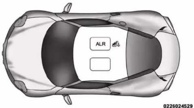
- ALR = Switchable Automatic Locking Retractor
• Top Tether Anchorage Symbol
THINGSTOKNOWBEFORESTARTINGYOURVEHICLE63
| What is the weight limit (child's weight + weight of the child restraint) for using the Tether Anchor with the seat belt to attach a forward facing child restraint? | Weight limit of the Child Restraint Always use the tether anchor when using the seat belt to install a forward facing child restraint, up to the recommended weight limit of the child restraint. | |
| Can the head restraints be removed? | No | |
| Can the buckle stalk be twisted to tighten the seat belt against the belt path of the child restraint? | No Do not twist the buckle stalk in a seating position with an ALR retractor. | |
InstallingAChildRestraintWithASwitchable AutomaticLockingRetractor(ALR):
-
Place the child seat in the center of the seating position. Move the vehicle seat as far rearward as possible to keep the child as far from the advanced passenger air bag as possible.
-
Pull enough of the seat belt webbing from the retractor to pass it through the belt path of the child restraint. Do not twist the belt webbing in the belt path.
- Slide the latch plate into the buckle until you hear a "click."
- Pull on the webbing to make the lap portion tight against the child seat.
- To lock the seat belt, pull down on the shoulder part of the belt until you have pulled all the seat belt webbing out of the retractor. Then, allow the webbing to retract back into the retractor. As the webbing retracts, you will hear a clicking sound. This means the seat belt is now in the Automatic Locking mode.
- Try to pull the webbing out of the retractor. If it is locked, you should not be able to pull out any webbing. If the retractor is not locked, repeat step 5.
- Finally, pull up on any excess webbing to tighten the lap portion around the child restraint while you push the child restraint rearward and downward into the vehicle seat.
- If the child restraint has a top tether strap and the seating position has a top tether anchorage, connect the tether strap to the anchorage and tighten the tether
strap. See the section "Installing Child Restraints Using The Top Tether Anchorage" for directions to attach a tether anchor.
- Test that the child restraint is installed tightly by pulling back and forth on the child seat at the belt path. It should not move more than 1 inch (25.4 mm) in any direction.
Any seat belt system will loosen with time, so check the belt occasionally, and pull it tight if necessary.
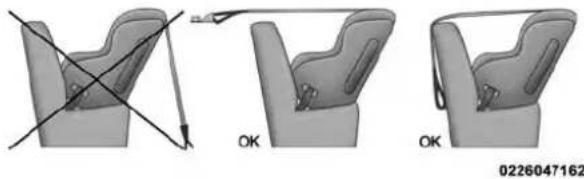
InstallingChildRestraintsUsingTheTopTether Anchorage:
WARNING!
Donotattachatetherstrapforarear-facingcarseat toanylocationinfrontofthecarseat, including the seatframeoratetheranchorage. Only attach the
(Continued)
WARNING!(Continued)
tetherstrapofarear-facingcarseattothetether anchoragethatisapprovedforthatseatingposition, locatedbehindthetopofthevehicleseat.Seethe section"LowerAnchorsandTethersforCHildren (LATCH)RestraintSystem"forthelocationofapprovedtetheranchoragesinyourvehicle.
THINGSTOKNOWBEFORESTARTINGYOURVEHICLE65
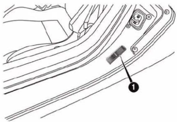
Always use the tether anchor when using the seat belt to install a forward facing child restraint, up to the recommended weight limit of the child restraint. This vehicle is equipped with a tether anchorage, located behind the front passenger seat, near the floor.
natural_image
Line drawing of a car seatbelt mechanism with a black arrow indicating the direction (no text or symbols present)UpperTetherAnchorage
- Look behind the seating position where you plan to install the child restraint to find the tether anchorage. You may need to tilt the seatback forward to provide better access to the tether anchorage.
- Route the tether strap around the outboard side of the head restraint to the tether anchorage.
- Attach the tether strap hook of the child restraint to the top tether anchorage.
- Remove slack in the tether strap according to the child restraint manufacturer's instructions.
WARNING!
Anincorrectlyanchoredtetherstrapcouldleadto increasedheadmotionandpossibleinjurytothe child.Useonlytheanchoragepositiondirectlybehindthechildseattosecureachildrestrainttop tetherstrap.
TransportingPets
Deploying air bags could harm your pet. An unrestrained pet will be thrown about and possibly injured, or injure a passenger during panic braking or in an collision.
Pets should be restrained in pet harnesses or pet carriers that are secured by seat belts.
ENGINEBREAK-INRECOMMENDATIONS
A long break-in period is not required for the drivetrain (engine, transmission, and rear axle) in your new vehicle. Following these few simple guidelines is all that is necessary for a good break-in.
For the first 200 miles (300 km):
- Driving your vehicle with new transmission requires no special techniques but, to reach optimal shifting
quality, it's preferred to use only Natural DNA mode in the first 125 miles (200 km), avoiding in this phase very aggressive driving.
- Avoid driving at a constant speed, either fast or slow, for long periods.
- Do not make any full throttle starts and avoid full throttle acceleration while cruising within the posted speed limits of local traffic laws.
- Use the proper gear for your speed range.
- Wait until the engine has reached normal operating temperature before driving at the recommended maximum break-in speed.
- Avoid excessive idling.
- Check the engine oil level at every fuel fill.
THINGSTOKNOWBEFORESTARTINGYOURVEHICLE67
NOTE:A new engine will consume some oil during the first few thousand miles (kilometers) of operation. This should be considered a normal part of the break-in and not interpreted as a sign of difficulty.
SAFETYTIPS
TransportingPassengers
NEVER TRANSPORT PASSENGERS IN THE CARGO AREA.
WARNING!
- Donotleavechildrenoranimalsinsideparked vehiclesinhotweather.Interiorheatbuild-upmay causeseriousinjuryordeath.
(Continued)
- Itisextremelydangeroustorideinacargoarea, insideoroutsideofvehicle.Inacollision,people ridingintheseareasaremorelikelytobeseriously injuredorkilled.
- Donotallowpeopletorideinanyareaofyour vehiclethatisnotequippedwithseatsandseatbelts.
- Besureeveryoneinyourvehicleisinaseatand usingaseatbeltproperly.
ExhaustGas
WARNING!
Exhaustgasescaninjureorkill. They contain carbon monoxide(CO), which is colorless and odorless. Breathing it can make you unconscious and can
(Continued)
WARNING!(Continued)
eventuallypoisonyou.Toavoidbreathing(CO), followthesesafetytips:
- Donotruntheengineinaclosedgarageorin confinedareasanylongerthanneededtomove yourvehicleinoroutofthearea.
- If you are required to drivewith the trunk/lift gate/reard oors open, makes sure that all windows are closed and the climate control BLOWER switch this set at high speed. DONOT usethere circulation mode.
- Ifitisnecessarytositinaparkedvehiclewiththe engineerunning,adjustyourheatingorcooling controlstoforceoutsideairintothevehicle.Setthe blowerathighspeed.
The best protection against carbon monoxide entry into the vehicle body is a properly maintained engine exhaust system.
Whenever a change is noticed in the sound of the exhaust system, when exhaust fumes can be detected inside the vehicle, or when the underside or rear of the vehicle is damaged, have a competent mechanic inspect the complete exhaust system and adjacent body areas for broken, damaged, deteriorated, or mispositioned parts. Open seams or loose connections could permit exhaust fumes to seep into the passenger compartment. In addition, inspect the exhaust system each time the vehicle is raised for lubrication or oil change. Replace as required.
SafetyChecksYouShouldMakeInsideThe Vehicle
SeatBelts
Inspect the belt system periodically, checking for cuts, frays, and loose parts. Damaged parts must be replaced immediately. Do not disassemble or modify the system. Front seat belt assemblies must be replaced after a collision. Seat belt assemblies must be replaced after a collision if they have been damaged (i.e., bent retractor, torn webbing, etc.). If there is any question regarding belt or retractor condition, replace the belt.
AirBagWarningLight
The light should come on and remain on for four to eight seconds as a bulb check when the ignition is first cycled to ON. If the light is not lit during starting, see your authorized dealer. If the light stays on, flickers, or comes on while driving, have the system checked by an authorized dealer.
Defroster
Check operation by selecting the defrost mode and place the blower control on high speed. You should be able to feel the air directed against the windshield. See your authorized dealer for service if your defroster is inoperable.
Always use floor mats designed to fit the foot well of your vehicle. Use only floor mats that leave the pedal area unobstructed and that are firmly secured so that they cannot slip out of position and interfere with the pedals or impair safe operation of your vehicle in other ways.
PeriodicSafetyChecksYouShouldMakeOutside TheVehicle
Tires
Examine tires for excessive tread wear and uneven wear patterns. Check for stones, nails, glass, or other objects lodged in the tread. Inspect the tread and sidewall for cuts and cracks. Check the wheel nuts for tightness. Check the tires for proper pressure.
Lights
Have someone observe the operation of brake lights and exterior lights while you work the controls. Check turn signal and high beam indicator lights on the instrument panel.
DoorLatches
Check for positive closing, latching, and locking.
FluidLeaks
Check area under vehicle after overnight parking for fuel, engine coolant, oil, or other fluid leaks. Also, if gasoline fumes are detected or if fuel, power steering fluid (if equipped), or brake fluid leaks are suspected, the cause should be located and corrected immediately.
UNDERSTANDINGTHEFEATURESOFYOURVEHICLE
CONTENTS
■MIRRORS....74
□Inside Day/Night Mirror....74
□Outside Mirrors....74
□Power Mirrors....75
□Folding Mirrors. 76
□Heated Mirrors....7 7
■SEATS
□Manual Seats....7 7
□Non-Adjustable Head Restraints....79
■TO OPEN AND CLOSE THE DECKLID....80
■LIGHTS....84
□Multifunction Lever. 84
□Headlights....84
□Daytime Running Lights....85
□High Beams 85
7 7□Flash-To-Pass....8 5
□Parking Lights....86
□Turn Signals 86
72 UNDERSTANDING THE FEATURES OF YOUR VEHICLE
□Lane Change Assist....86
□Follow Me Home/Headlight Delay —
If Equipped....8 6
□Dimmer Controls....87
□Interior Light....8 8
■WINDSHIELD WIPERS AND WASHERS ..... 8 9
□Intermittent Wiper System....89
□Windshield Wiper Operation ..... 9 0
□Mist....90
□Windshield Washers....90
■TILT/TELESCOPING STEERING COLUMN . . . 9 1
■ELECTRONIC SPEED CONTROL —
IF EQUIPPED....92
□To Activate....92
□To Set A Desired Speed....93
□To Deactivate....93
□To Resume Speed 93
□To Vary The Speed Setting ..... 9 4
□ To Accelerate For Passing....95
■PARKING SENSORS — IF EQUIPPED .....9 6
□ Activation/Deactivation.....96
□Acoustic Signal 96
□Indications On Display — If Equipped . . . . . . 9 7
□ Fault Indication....98
□GeneralWarnings....98
■POWER OUTLETS....101
CIGAR LIGHTER AND ASH RECEIVER — IF EQUIPPED. 103
■CUPHOLDER....104
■STORAGE....105
UNDERSTANDINGTHEFEATURESOFYOURVEHICLE73
□Seatback Storage....105
□Console Features....105
□Rear Compartment Storage....106
74UNDERSTANDINGTHEFEATURESOFYOURVEHICLE
MIRRORS
InsideDay/NightMirror
A single ball joint mirror is provided in the vehicle. It is a twist on mirror that has a fixed position at the windshield. The mirror installs on the windshield button with a counterclockwise rotation and requires no tools for mounting. The mirror head can be adjusted up, down, left, and right for various drivers. The mirror should be adjusted to center on the view through the rear window.
Headlight glare from vehicles behind you can be reduced by moving the small control under the mirror to the night position (toward the rear of the vehicle). The mirror should be adjusted while the small control under the mirror is set in the day position (toward the windshield).
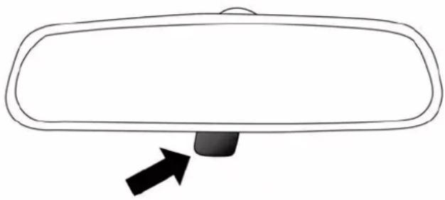
natural_image
Simple line drawing of a car rearview mirror with an arrow pointing to the side (no text or symbols)AdjustingRearviewMirror
OutsideMirrors
To receive maximum benefit, adjust the outside mirrors to center on the adjacent lane of traffic and a slight overlap of the view obtained from the inside mirror.
UNDERSTANDINGTHEFEATURESOFYOURVEHICLE75
NOTE: The passenger side convex outside mirror will give a much wider view to the rear, and especially of the lane next to your vehicle.
WARNING!
Vehiclesandotherobjectsseeninthepassengerside convexmirrorwilllooksmallerandfartheraway thantheyreallyare.Relyingtoomuchonyour passengersidemirrorcouldcauseyoutocollidewith anothervehicleorotherobject.Useyourinside mirrorwhenjudgingthesizeordistanceofavehicle seeninthepassengersidemirror.
PowerMirrors
The power mirror controls are located on the center console.
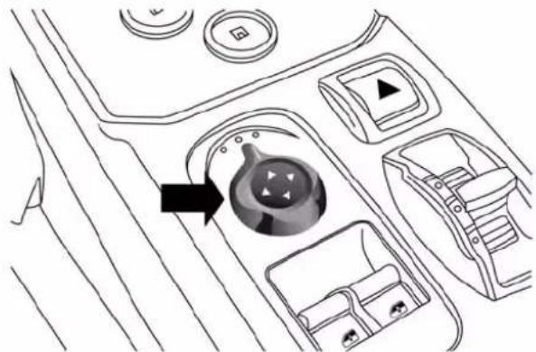
natural_image
Diagram of a car interior showing dashboard, steering wheel, and directional control buttons (no text or labels)PowerMirrorControl
76UNDERSTANDINGTHEFEATURESOFYOURVEHICLE
The power mirror controls consist of mirror select knob and a four-way mirror control switch. To adjust a mirror, turn the power mirror control knob to the left or right to select the mirror that you want to adjust.
Using the mirror control switch, press on any of the four arrows for the direction that you want the mirror to move.
FoldingMirrors
The exterior mirrors are hinged to allow the mirror to pivot forward or rearward to help avoid damage. The mirror has three detent positions: full forward, full rearward and normal.
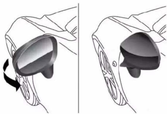
natural_image
Illustration of a hand holding a VR headset with a rotating button, shown from two different angles (no text or symbols)FoldingMirrors
UNDERSTANDINGTHEFEATURESOFYOURVEHICLE77
HeatedMirrors

These mirrors are heated to melt frost or ice. This feature can be activated whenever you turn on the mirror defroster.
SEATS
Seats are a part of the Occupant Restraint System of the vehicle.
WARNING!
- Itisdangeroustorideinacargoarea, insideor outsideofvehicle. Inacollision, peopleriding in theseareasaremorelikelytobeseriouslyinjured orkilled.
WARNING!(Continued)
- Donotallowpeopletorideinanyareaofyour vehiclethatisnotequippedwithseatsandseat belts.Inacollision,peopleridingintheseareasare morelikelytobeseriouslyinjuredorkilled.
- Besureeveryoneinyourvehicleisinaseatand usingaseatbeltproperly.
ManualSeats
ForwardAndRearwardAdjustment
The adjusting bar is at the front of the driver seat, near the floor. Pull the bar upward to move the seat forward or rearward. Release the bar once the seat is in the desired position. Then, using body pressure, move forward and rearward on the seat to be sure that the seat adjusters have latched.
(Continued)
78UNDERSTANDINGTHEFEATURESOFYOURVEHICLE
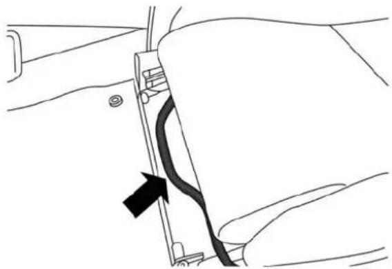
natural_image
Line drawing of a hand holding a cable or connector with a black arrow pointing to a cable (no text or symbols present)SeatAdjustmentBar
SeatHeightAdjustment
In order to achieve the ideal driving position, the height of the seats can also be adjusted. Tools are required to make this height adjustment. Contact your authorized dealership.
ReclinerAdjustment
The recliner lever is located on the outboard side of the seat. To recline the seat, lean forward slightly, pull the recliner lever upward, lean backward until the seat is in the desired position, and release the lever. To return the seat to its full upright position, lean forward, pull the recliner lever upward and hold it until the seat returns to its full upright position.
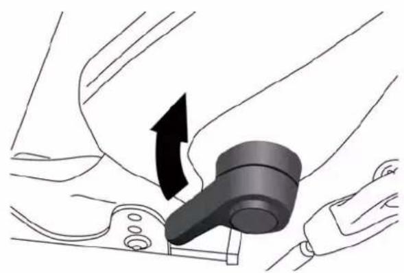
natural_image
Diagram of a car seatbelt mechanism with an arrow indicating clockwise motion (no text or symbols present)ReclineLever
WARNING!
- Adjustingaseatwhiledrivingmaybedangerous. Movingaseatwhiledrivingcouldresultinlossof
(Continued)
UNDERSTANDINGTHEFEATURESOFYOURVEHICLE79
WARNING!(Continued)
controlwhichcouldcauseacollisionandserious injuryordeath.
- Seatsshouldbeadjustedbeforefasteningtheseat beltsandwhilethevehicleisparked.Serious injuryordeathcouldresultfromapoorlyadjusted seatbelt.
- Donotridewiththeseatbackreclinedsothatthe shoulderbeltisnolongerrestingagainstyour chest.Inacollisionyoucouldslideundertheseat belt,whichcouldresultinseriousinjuryordeath.
Non-AdjustableHeadRestraints
The non-adjustable head restraints are form fitted into the upper structure of the seatback and are designed to reduce the risk of injury by restricting head movement in the event of a rear impact. The seatback should be properly adjusted to an upright position where the head
80UNDERSTANDINGTHEFEATURESOFYOURVEHICLE
restraint is positioned as close as possible to the back of your head.
WARNING!
Becertainthattheseatbackislockedsecurelyinto position. Otherwise, theseatwillnotprovide the properstabilityforpassengers. Animproperly latchedseatbackcouldcauseseriousinjury.
TOOPENANDCLOSETHEDECKLID
CAUTION!
- Topreventpossibledamage, donotslamthedecklidtocloseit. Useafirmdownwardpushatthe centerofthedecklidtoensurethedecklidlatchis fullyengaged.
(Continued)
CAUTION!(Continued)
- During normal car operation, the luggage compartment (located rear of the engine) can reach temperatures above 149 degrees. Donot transport objects in the luggage compartment that maybe damaged such temperatures. Donot place aerosolcans in the luggage compartment.
To open the decklid:
- Open the drivers side door.
- Pull the decklid release lever located on the rear of the drivers door sill.
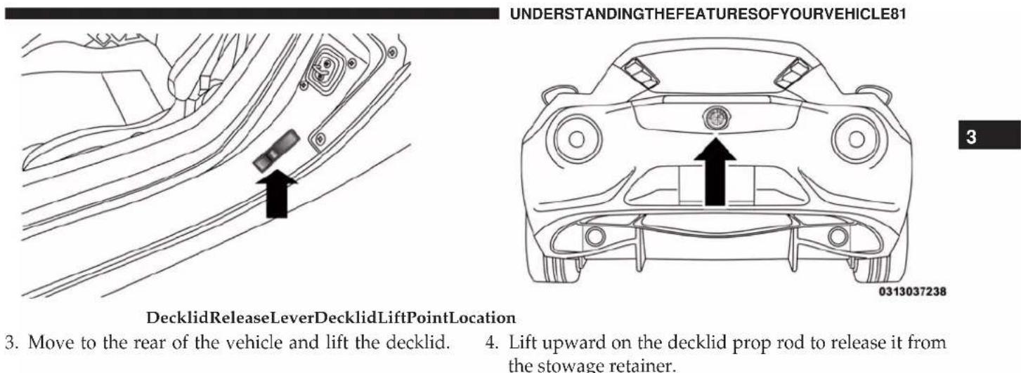
-
Move to the rear of the vehicle and lift the decklid.
-
Lift upward on the decklid prop rod to release it from the stowage retainer.
82UNDERSTANDINGTHEFEATURESOFYOURVEHICLE
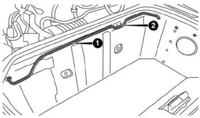
1 — Decklid Prop Rod
2 — Stowage Retainer Location
- Place the decklid prop rod in the decklid slot to secure the decklid in the open position.
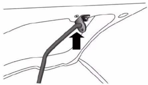
natural_image
Diagram of a mechanical component with an arrow indicating direction, no text or symbols presentDecklidPropRodSlot
CAUTION!
Topreventpossibledamage, donotslamthedecklid to closeit. Useafirmdownwardpushatthecenterof thedecklidtoensurethedecklidlatchisfully engaged.
WARNING!
- The maximum load limit fortheluggage compartment, in addition to the kits provided, is 33.1 lbs. (15 kg). Donot exceed them a maximum permitted load in the luggage compartment. When accessing the rear luggage compartment, donot come into contact with engine, or other components, that maybe hot and could burn you if touched.
- Accessstehluggagecompartmentonlywiththe vehiclestationary.Beforeexitingthevehicle,you
WARNING!(Continued)
shouldalwaysplacethevehicleintoFirstgear, applytheparkingbrake,andremovethekeyfrom theignition.Neverleavethekeyfobinthevehicle orinalocationaccessibletochildren.
- Thedecklidmaydropsuddenly, causing serious injury, if the supporting drodis not positioned correctly.
- Thedecklidmustalwaysbeclosedproperly,and thelockengaged,whilethevehicleisinmotions.
(Continued)
84UNDERSTANDINGTHEFEATURESOFYOURVEHICLE
LIGHTS
MultifunctionLever
The multifunction lever, located on the left side of the steering wheel, controls the operation of the headlights, headlight beam selection, passing light and turn signals.
NOTE: The external lights can only be turned on with the ignition in the ON/RUN position.
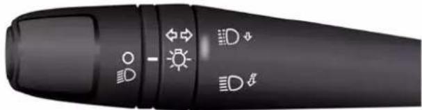
natural_image
Close-up of a black industrial control knob with icons for lighting, sun, and thermal (no text or symbols visible)MultifunctionLever
Headlights

Rotate the end of the multifunction lever upward to the first detent for headlight operation.
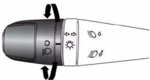
natural_image
Diagram of a device with directional arrows and icons, no readable text or symbolsHeadlightOperation
NOTE: When the headlights are turned on, the Daytime Running Lights will be deactivated.
DaytimeRunningLights
To activate the Daytime Running Lights (DRL), rotate the end of the multifunction lever to the Osymbol.
UNDERSTANDINGTHEFEATURESOFYOURVEHICLE85
NOTE: The low beams and side/tail lights will not be on with DRL.
HighBeams

With the low beams activated, pull the multifunction lever towards the steering wheel to turn on the high beams. A high beam symbol will illuminate in the cluster to indicate the high beams are on. Pull the multifunction lever a second time to switch the headlights back to low beam.
Flash-To-Pass
You can signal another vehicle with your headlights by partially pulling the multifunction lever toward the steering wheel. This will cause the high beam headlights to turn on until the lever is released.
86UNDERSTANDINGTHEFEATURESOFYOURVEHICLE
ParkingLights

To turn on the parking lights, remove the key or turn the ignition to OFF/LOCK position and turn on the headlights.
TurnSignals
Move the multifunction lever up or down and the arrows on each side of the instrument cluster flash to show proper operation of the front and rear turn signal lights.
NOTE: If either light remains on and does not flash, or there is a very fast flash rate, check for a defective outside light bulb. If an indicator fails to light when the lever is moved, it would suggest that the indicator bulb is defective.
LaneChangeAssist
Tap the lever up or down once, without moving beyond the detent, and the turn signal (right or left) will flash five times then automatically turn off.
FollowMeHome/HeadlightDelay—IfEquipped
When this feature is selected the driver can choose to have the headlights remain on for a preset period of time.
Activation
Remove the key or turn the ignition to the OFF/LOCK position, and pull the multifunction lever toward the steering wheel, within two minutes. Each time the lever is pulled, the activation of the lights will be extended by 30 seconds. The activation of the lights can be extended to a maximum of 210 seconds.
Deactivation
Pull the multifunction lever toward the steering wheel and hold it for more than two seconds.
DimmerControls
The dimmer controls are located on the left side of the instrument panel below the instrument cluster.
UNDERSTANDINGTHEFEATURESOFYOURVEHICLE87
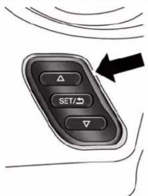
0314026746
DimmerControls
Pressing the up or down arrow will increase or decrease the brightness of the instrument panel lights.
88UNDERSTANDINGTHEFEATURESOFYOURVEHICLE
InteriorLight
The interior light is located in the headliner in between the sun visors. The interior light can be set to three different positions (Off/Left Position, Center Position, On/Right Position).
Using the interior light lens, press the lens to the right from its center position and the lights are always on. Press the lens to the left from its center position and the lights are always off. Leave the lens in the center position, and the light is turned on and off when the doors are opened or closed.
CAUTION!
Beforegettingoutofthevehiclebesurethatthe switchisinthecenterpositionorthatthelightsare offtoavoiddrainingthebattery.
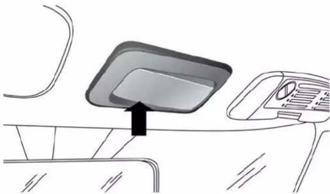
natural_image
Diagram of a car interior showing a monitor mounted on a vehicle chassis with a handle, no text or symbols presentInteriorLight(OffPositionShown)
InteriorLightTiming(CenterPosition)
There are four different modes of operation that can be activated in this position:
- When one door is opened a three minute timer is activated.
UNDERSTANDINGTHEFEATURESOFYOURVEHICLE89
- When the key is removed from the ignition (within two minutes of the ignition being turned off), a 10 second timer is activated.
- When the doors are unlocked with the Key Fob a 10 second timer is activated.
- When the doors are locked with the Key Fob the lights will turn off.
The windshield wiper/washer controls are located on the windshield wiper/washer lever on the right side of the steering column. The front wipers are operated by rotating a switch, located on the end of the lever.
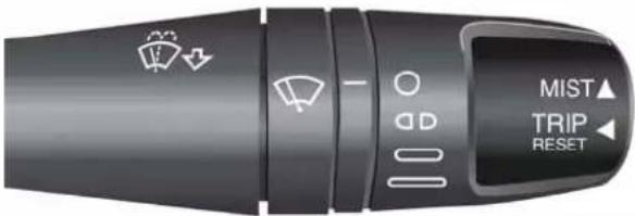
WindshieldWiper/WasherLever
IntermittentWiperSystem
Use the intermittent wiper when weather conditions make a single wiping cycle with a variable pause between cycles. Rotate the end of the multifunction lever to the first detent position. There are four possible delay intervals that depend on the vehicle speed.
90UNDERSTANDINGTHEFEATURESOFYOURVEHICLE
WindshieldWiperOperation
Rotate the end of the lever upward, to the first detent past the intermittent settings for low-speed wiper operation. Rotate the end of the lever upward to the second detent past the intermittent settings for high-speed wiper operation.
Mist
Use the mist feature when weather conditions make occasional usage of the wipers necessary. Push the lever upward to the mist position and release for a single wiping cycle.
NOTE: The mist feature does not activate the washer pump; therefore, no washer fluid will be sprayed on the windshield. The wash function must be used in order to spray the windshield with washer fluid.
WindshieldWashers
To use the washer, pull the lever toward you and hold while spray is desired. If the lever is pulled while in the delay range, the wiper will start and continue to operate for three wipe cycles after the lever is released, and then resume the intermittent interval previously selected.
If the lever is pulled while in the off position, the wipers will operate for three wipe cycles and then turn off.
WARNING!
Suddenlossofvisibilitythroughthewindshield couldleadtoacollision.Youmightnotseeother vehiclesorotherobstacles.Toavoidsuddenicingof thewindshieldduringfreezingweather,warmthe windshieldwithdefrosterbeforeandduringwind-shieldwasheruse.
TILT/TELESCOPINGSTEERINGCOLUMN
This feature allows you to tilt the steering column upward or downward. It also allows you to lengthen or shorten the steering column. The tilt/telescoping control handle is located below the steering wheel at the end of the steering column.
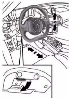
natural_image
Interior view of a car dashboard and steering wheel (no text or symbols visible)Tilt/TelescopingColumnLever
UNDERSTANDINGTHEFEATURESOFYOURVEHICLE91
To unlock the steering column, push the lever downward (toward the floor). To tilt the steering column, move the steering wheel upward or downward as desired. To lengthen or shorten the steering column, pull the steering wheel outward or push it inward as desired. To lock the steering column in position, push the lever upward until fully engaged.
WARNING!
Donotadjustthesteeringcolumnwhiledriving. Adjustingthesteeringcolumnwhiledrivingordrivingwiththesteeringcolumnunlocked,couldcause thedrivertolosecontrolofthevehicle.Failureto followthiswarningmayresultinseriousinjuryor death.
92UNDERSTANDINGTHEFEATURESOFYOURVEHICLE ELECTRONICSPEEDCONTROL—IFEQUIPPED
When engaged, the Electronic Speed Control takes over accelerator operations at speeds greater than 18 mph (30 km/h) up to the maximum speed of 105 mph (170 km/h).
The Electronic Speed Control Lever is located on the left side of the steering column.
NOTE: In order to ensure proper operation, the Electronic Speed Control system has been designed to shut down if multiple speed control functions are operated at the same time. If this occurs, the Electronic Speed Control system can be reactivated rotating the end of the multifunction lever (On/Off) and resetting the desired vehicle set speed.
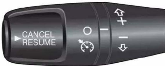
ElectronicSpeedControlLever
ToActivate
Rotate the end of the multifunction lever to activate the Electronic Speed Control. The Cruise Indicator Light in the Electronic Vehicle Information Center (EVIC) will illuminate. To turn the system off, rotate the end of the multifunction lever to the "O" position. The Cruise
Indicator Light will turn off. The system should be turned off when not in use.
WARNING!
LeavingtheElectronicSpeedControlsystemon whennotinuseisdangerous.Youcouldaccidentally setthesystemorcauseittogofasterthanyouwant. Youcouldlosecontrolandhaveanaccident.Always leavethesystemOFFwhenyouarenotusingit.
ToSetADesiredSpeed
Turn the Electronic Speed Control ON. When the vehicle has reached the desired speed, move the electronic speed control lever upward SET(+) and release. Release the accelerator and the vehicle will operate at the selected speed.
UNDERSTANDINGTHEFEATURESOFYOURVEHICLE93
NOTE: The vehicle should be traveling at a steady speed and on level ground before moving the electronic speed control lever upward SET(+).
ToDeactivate
A soft tap on the brake pedal, pushing the RESUME/CANCEL button, or normal brake pressure while slowing the vehicle will deactivate Electronic Speed Control without erasing the set speed memory. Rotating the end of the multifunction lever to the "O" position or turning the ignition switch OFF erases the set speed memory.
ToResumeSpeed
To resume a previously set speed, push the RESUME button and release. Resume can be used at any speed above 18 mph (30 km/h).
94UNDERSTANDINGTHEFEATURESOFYOURVEHICLE
ToVaryTheSpeedSetting
ToIncreaseSpeed
When the Electronic Speed Control is set, you can increase speed by tapping the Speed Control lever up (+).
The speed increment shown is dependant on the speed of U.S. (mph) or Metric (km/h) units:
U.S.Speed(mph)
- Tapping the Speed Control lever up (+) once will result in a 1 mph increase in set speed. Each subsequent tap of the lever results in an increase of 1 mph.
- If the lever is continually help up, the set speed will continue to increase until the lever is released, then the new set speed will be established.
MetricSpeed(km/h)
- Tapping the Speed Control lever up (+) once will result in a 2 km/h increase in set speed. Each subsequent tap of the lever results in an increase of 2 km/h.
- If the lever is continually help up, the set speed will continue to increase until the lever is released, then the new set speed will be established.
ToDecreaseSpeed
When the Electronic Speed Control is set, you can decrease speed by tapping the Speed Control lever down (-).
The speed decrement shown is dependant on the speed of U.S. (mph) or Metric (km/h) units:
U.S.Speed(mph)
- Tapping the Speed Control lever down (-) once will result in a 1 mph decrease in set speed. Each subsequent tap of the lever results in a decrease of 1 mph.
- If the lever is continually held down, the set speed will continue to decrease until the lever is released, then the new set speed will be established.
UNDERSTANDINGTHEFEATURESOFYOURVEHICLE95
MetricSpeed(km/h)
- Tapping the Speed Control lever down (-) once will result in a 2km / h decrease in set speed. Each subsequent tap of the lever results in a decrease of 2km / h .
- If the lever is continually held down, the set speed will continue to decrease until the lever is released, then the new set speed will be established.
ToAccelerateForPassing
Press the accelerator as you would normally. When the pedal is released, the vehicle will return to the set speed.
96UNDERSTANDINGTHEFEATURESOFYOURVEHICLE
PARKINGSENSORS—IFEQUIPPED
They are located in the rear bumper and their function is to detect the presence of any obstacles near the rear part of the car; they consequently inform the driver, through an intermittent acoustic signal.
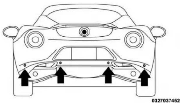
natural_image
Top-down line drawing of a car's front and rear views with directional arrows indicating movement or force (no text or symbols)ParkingSensors
Activation/Deactivation
The sensors are automatically activated when reverse gear is engaged. As the obstacle behind the car gets closer, the acoustic signal becomes more frequent.
AcousticSignal
When reverse gear is engaged and there is an obstacle behind the vehicle, an acoustic signal is emitted which varies according to the distance of the bumper from the obstacle.
The frequency of the acoustic signal:
- Increases as the distance between car and obstacle decreases, culminating in a continuous acoustic signal when the distance is less than approximately 12 in (30 cm).
• Decreases if the distance from the obstacle increases, until the signal ceases entirely.
UNDERSTANDINGTHEFEATURESOFYOURVEHICLE97
- Remains constant if the distance between car and obstacle remains unchanged; if this situation concerns the side sensors, the signal will stop after approximately 3 seconds to avoid, for example, indications in the event of manoeuvres along a wall.
If several obstacles are detected by the sensors, only the nearest one is considered.
IndicationsOnDisplay—IfEquipped
When the sensors are activated, the screen appears on the display.
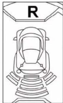
natural_image
Line drawing of a seat with a 'R' sign above it, no text or symbols present0327037451
ParkingSensorsScreen
Obstacle presence and distance information is therefore provided both by the acoustic signal and the instrument panel display.
The system indicates a detected obstacle by displaying an arc in one or more positions according to the distance of the obstacle and its position in relation to the car.
98UNDERSTANDINGTHEFEATURESOFYOURVEHICLE
If an obstacle is detected in the rear central area, the display shows all the arcs in the rear central area, up to the one that corresponds to the position of the obstacle itself.
The signal is similar for obstacles in the rear left or right area.
The arc that corresponds to the position of the obstacle will flash.
The color on the display depends on the distance from and position of the obstacle.
The car is close to the obstacle when the display shows a single constant arc and emits a continuous sound.
If there are several obstacles, the closest one is indicated.
FaultIndication
Parking sensor failures, if any, will be indicated when reverse is engaged by the switching on of the warning light on the instrument panel together with the message on the display.
GeneralWarnings
When parking, take the utmost care over obstacles that may be above or under the sensor.
Under certain circumstances, objects close to the vehicle are not detected by the system and could therefore cause damage to the car or be damaged themselves.
Some conditions may influence the performance of the parking sensors:
- The presence of ice, snow, mud or multiple layers of paint on the sensor surface may cause reduced sensitivity of the sensor itself and therefore reduce the system performance.
- Mechanical interference (e.g washing the car, rain, strong wind, hail) may cause the sensor to detect a non-existent obstacle ("echo interference").
- The presence of ultrasonic systems (e.g. pneumatic brake systems of trucks or pneumatic drills) near the car could alter the signals sent by the sensor.
- The variation in sensor position, caused by variation in ride (due to suspension component wear), changing tires, overloaded car, or tuning that lowers the car, for example, may affect parking sensor system performance.
NOTE: The sensor must be free from mud, dirt snow or ice in order for the system to operate correctly. Be careful not to scratch or damage the sensors while cleaning them. Avoid using dry, rough or hard cloths. The sensors must be washed using clean water, with the addition of car shampoo if necessary. When using special washing equipment such as high pressure jets or steam cleaning, clean the sensors very quickly keeping the jet more than 4 in (10 cm) away. Also, do not apply stickers to the sensors.
100UNDERSTANDINGTHEFEATURESOFYOURVEHICLE
CAUTION!
- TheParkingSensorsystemisonlaparkingaid anditisunabletorecognizeeveryobstacle,includingsmallobstacles.Parkingcurbsmightbetemporarilydetectedornotdetectedatall.Obstacles locatedaboveorbelowthesensorswillnotbedetectedwhentheyareincloseproximity
- The vehicle must bedrivenslowly when using the Parking Sensorsystem in order to be able to stop in tim when an obstacle is detected. It is recommended that the driver looks over his or her should be when using the Parking Sensorsystem.
WARNING!
Driversmustbecarefulwhenbackingupevenwhen usingtheParkingSensorsystem.Alwayscheckcarefullybehindyourvehicle,andbesuretocheckfor pedestrians,animals,othervehicles,obstructions,or blindspotsbeforebackingup.Youareresponsible forthesafetyofyoursurroundingsandmustcontinuetopayattentionwhilebackingup.Failureretodo socanresultinseriousinjuryordeath.
POWEROUTLETS
Your vehicle is equipped with a 12 Volt (13 Amp) power outlet that can be used to power cellular phones, small electronics and other low powered electrical accessories.
UNDERSTANDINGTHEFEATURESOFYOURVEHICLE101
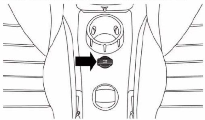
natural_image
Diagram of a human torso with a device inserted into the chest area, showing no text or symbols.FrontPowerOutlet
102UNDERSTANDINGTHEFEATURESOFYOURVEHICLE
The power outlet is located on the central tunnel, between the two cup holders. It only operates with the ignition key at MAR-ON.
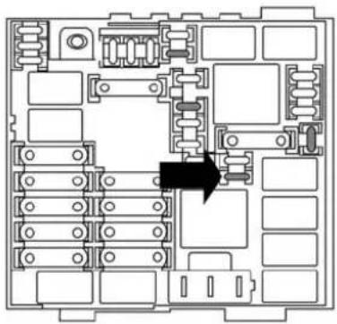
natural_image
Top-down schematic of an electronic circuit board layout with no visible text or symbolsPowerOutletFuseLocation
WARNING!
Toavoidseriousinjuryordeath:
- Onlydevicesdesignedforuseinthistypeofoutlet shouldbeinsertedintoany12Voltoutlet.
- Donottouchwithwethands.
- Closethelidwhennotinuseandwhiledrivingthe vehicle.
- If this outletismishandled, it may cause an electric shock and failure.
CAUTION!
- Manyaccessories that can be plugged in draw power from the vehicle's battery, even when not in use (i.e., cellular phones, etc.). Eventually, if plugged in longenough, the vehicle's battery will
(Continued)
UNDERSTANDINGTHEFEATURESOFYOURVEHICLE103
CAUTION!(Continued)
dischargesufficientlytodegradebatterylifeand/or preventtheenginefromstarting.
- Accessories that draw higher power (i.e., coolers, vacuum cleaners, lights, etc.) will degrade the battery even more quickly. Only use these intermittently and with greater caution.
- Aftertheuseofhighpowerdrawaccessories,or longperiodsofthevehiclenotbeingstarted(with accessoriesstillpluggedin),thevehiclemustbe drivenasufficientlengthoftimetoallowthe generatortorechargethevehicle'sbattery.
CAUTION!
- Donotexceedthemaximumpowerof180Watts(15 Amps)at12Volts.Ifthe180Watts(15Amps)power
CAUTION!(Continued)
ratingisexceeded, the fuse protecting the system will need to be replaced.
- Poweroutletsaredesignedforaccessoryplugs only.Donotinsertanyotherobjectinthepower outletsasthiswilldamagetheoutletandblowthe fuse.Improperuseofthepoweroutletcancause damagenotcoveredbyyourNewVehicleLimited Warranty.
CIGARLIGHTERANDASHRECEIVER—IF EQUIPPED
The cigar lighter and ash receiver are located on the central tunnel. To activate the cigar lighter, press the button down. After a few seconds the button automatically returns to its initial position, and the cigar lighter is ready for use.
(Continued)
104UNDERSTANDINGTHEFEATURESOFYOURVEHICLE
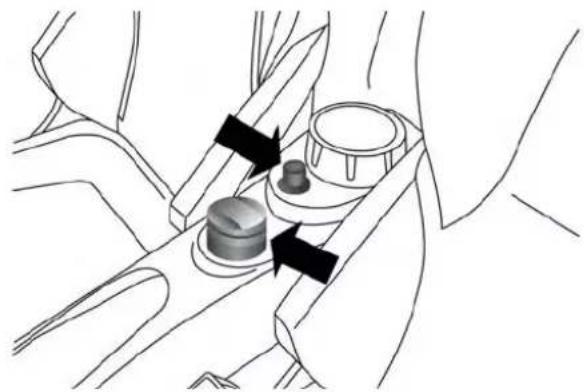
natural_image
Diagram of a mechanical assembly with arrows indicating direction (no text or symbols present)CigarLighter/Ashtray—IfEquipped
NOTE:
• Always check that the cigar lighter is switched off.
- Do not connect devices with power higher than 180 W to the socket.
- Do not damage the socket by using unsuitable adaptors.
CUPHOLDER
A cupholder is located in the rear of the center console.
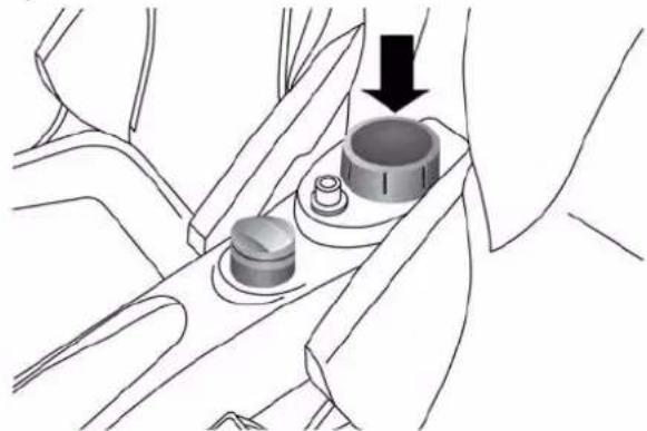
natural_image
Diagram of a mechanical component with a downward arrow indicating motion or force (no text or symbols present)CenterConsoleCupholder
STORAGE
SeatbackStorage
Located in the back of both the driver and passenger front seats are pockets that can be used for storage.
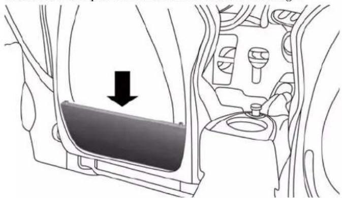
natural_image
Diagram of a car interior showing a vehicle's side panel with a downward arrow indicating motion (no text or symbols present)DriversSideSeatbackStorage
UNDERSTANDINGTHEFEATURESOFYOURVEHICLE105
ConsoleFeatures
There is a cargo pouch storage area located between the driver and passengers seat (If Equipped).
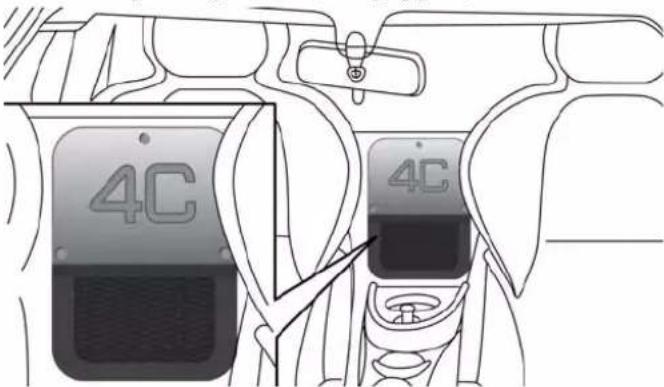
CargoPouchStorageLocation
106UNDERSTANDINGTHEFEATURESOFYOURVEHICLE
RearCompartmentStorage
CAUTION!
- Topreventpossibledamage, donotslamthedecklidtocloseit. Useafirmdownwardpushatthe centerofthedecklidtoensurethedecklidlatchis fullyengaged.
- During normal car operation, the luggage compartment (located rear of the engine) can reach temperatures above 149 degrees. Donot transport objects in the luggage compartment that maybe damaged at such temperatures. Donot place aerosol cans in the luggage compartment.
Your vehicle is equipped with a open storage area located under the decklid.
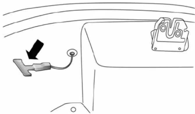
natural_image
Diagram showing a car interior with a switch and a mounted device (no text or symbols)DecklidEmergencyRelease
WARNING!
Donotallowchildrentohaveaccesstorearstorage compartment. Alwaysclosethehoodwhenyour
(Continued)
WARNING!(Continued)
vehicleisunattended.Onceintherearstoragecompartment,youngchildrenmaynotbeabletoescape. Iftrappedintherearcompartment,childrencandie fromsuffocationorheatstroke.
As a security measure, an internal decklid emergency release lever is built into the rear compartment storage latching mechanism. In a event of a person trapped inside the storage compartment, the decklid can be simply opened by pulling on the phosphorescent handle attached to the decklid latching mechanism.
UNDERSTANDINGTHEFEATURESOFYOURVEHICLE107
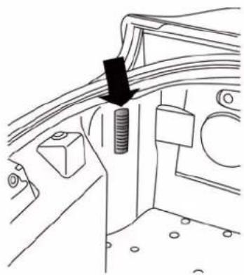
natural_image
Technical line drawing of a mechanical component with a black arrow pointing to a bolted part (no text or symbols present)RearCompartmentLight
108UNDERSTANDINGTHEFEATURESOFYOURVEHICLE
WARNING!
- The maximum load limit fortheluggage compartment (located rear of the engine), in addition to the kits provided, is 33 lbs. (15 kg). Donot exceed the maximum permitted load in the luggage compartment. When accessing there are luggage compartment, donot come into contact with engine, or other components, that may be hot and could burn you if touched.
- Accesstheluggagecompartmentonlywiththe vehiclestationary.Beforeexitingavehicle,you
WARNING!(Continued)
shouldalwaysshiftthevehicleintoPARK,remove thekeyfromtheignition,andapplytheparking brake.Neverleavethekeyfobinthevehicleorin allocationaccessibletochildren.
- Thedecklidmaydropsuddenly, causing serious injury, if the supporting drodis not positioned correctly.
- Thedecklidmustalwaysbeclosedproperly,and thelockengaged,whilethevehicleisinmotions.
(Continued)
UNDERSTANDING YOUR INSTRUMENT PANEL
CONTENTS
■INSTRUMENT PANEL FEATURES....1 1 0
■INSTRUMENT CLUSTER....1 1 1
■INSTRUMENT CLUSTER DESCRIPTIONS ..... 1 1 2
■ELECTRONIC VEHICLE INFORMATION CENTER (EVIC)....124
□Electronic Vehicle Information Center (EVIC) Setup Menu....126
□Change Engine Oil Indicator System . . . . . . .136
□Trip Computer....137
□Values Displayed....139
■RADIO SYSTEM. . . . . . . . . . . . . . . . . . . . . . . . . . . . . . . . . . . . . . . . . . . . . . . . . 141
■HEATING AND VENTILATION .....142
□ Manual Climate Controls With A/C .....142
110 UNDERSTANDING YOUR INSTRUMENT PANEL INSTRUMENT PANEL FEATURES
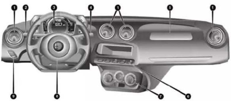
1 — Climate Control Air Outlets 6 — Switch Bank (A/C/Door Lock Switch/Door Mirror Demisting)
2 — Exterior Light Lever 7 — Climate Controls
3 — Instrument Cluster 8 — Driver Air Bag
4 — Washer/Wiper Lever 9 — EVIC Control Buttons
5 — Passenger Air Bag
INSTRUMENTCLUSTER
UNDERSTANDING YOUR INSTRUMENT PANEL 111
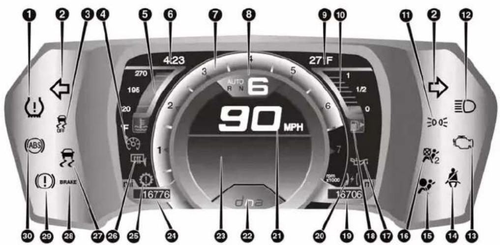
112UNDERSTANDINGYOURINSTRUMENTPANEL
INSTRUMENTCLUSTERDESCRIPTIONS
- TirePressureMonitoringTelltaleLight—IfEquipped

Each tire, including the spare (if provided), should be checked monthly when cold and inflated to the inflation pressure recommended by the vehicle manufacturer on the vehicle placard or tire inflation pressure label. (If your vehicle has tires of a different size than the size indicated on the vehicle placard or tire inflation pressure label, you should determine the proper tire inflation pressure for those tires.)
As an added safety feature, your vehicle has been equipped with a Tire Pressure Monitoring System (TPMS) that illuminates a low tire pressure telltale when one or more of your tires is significantly under-inflated. Accordingly, when the low tire pressure telltale illuminates, you should stop and check your tires as soon as possible, and inflate them to the proper pressure. Driving on a significantly under-inflated tire causes the tire to overheat and can lead to tire failure. Under-inflation also reduces fuel efficiency and tire tread life, and may affect the vehicle's handling and stopping ability.
Please note that the TPMS is not a substitute for proper tire maintenance, and it is the driver's responsibility to maintain correct tire pressure, even if under-inflation has not reached the level to trigger illumination of the TPMS low tire pressure telltale.
Your vehicle has also been equipped with a TPMS malfunction indicator to indicate when the system is not operating properly. The TPMS malfunction indicator is combined with the low tire pressure telltale. When the system detects a malfunction, the telltale will flash for approximately one minute and then remain continuously illuminated. This sequence will continue upon subsequent vehicle start-ups as long as the malfunction exists. When the malfunction indicator is illuminated, the system may not be able to detect or signal low tire pressure
as intended. TPMS malfunctions may occur for a variety of reasons, including the installation of replacement or alternate tires or wheels on the vehicle that prevent the TPMS from functioning properly. Always check the TPMS malfunction telltale after replacing one or more tires or wheels on your vehicle, to ensure that the replacement or alternate tires and wheels allow the TPMS to continue to function properly.
WARNING!
TheTPMShasbeenoptimizedfortheoriginal equipmenttiresandwheels.TPMSpressuresand warninghavebeenestablishedforthetiresize equippedonyourvehicle.Undesirablesystemoperationorsensordamagemayresultwhenusingreplacementequipmentthatisnotofthesamesize, type,and/orstyle.Aftermarketwheelscancause
WARNING!(Continued)
sensordamage.Donotusetiresealantfromacanor balancebeadsifyourvehicleisequippedwitha TPMS,asdamagetothesensorsmayresult.
2. TurnSignalIndicators
The arrows will flash in unison with the exterior turn signal, when using the turn signal lever.
3. Electronic Stability Control (ESC) OFF Indicator Light

This light indicates the Electronic Stability Control (ESC) is off.
(Continued)
114 UNDERSTANDING YOUR INSTRUMENT PANEL
- ElectronicSpeedControlSetIndicatorLight—If Equipped

This light will turn on when the electronic speed control is set.
5.TemperatureGauge
The temperature gauge shows engine coolant temperature. Any reading within the normal range indicates that the engine cooling system is operating satisfactorily.
The digital gauge will likely indicate a higher temperature when driving in hot weather, or up mountain grades. It should not be allowed to exceed the upper limits of the normal operating range.
NOTE: Driving with a hot engine cooling system could damage your vehicle. The digital warning light may switch on (together with a message on the display) to indicate that the coolant temperature is too high; in this case, stop the engine and contact a dedicated authorized dealership.
WARNING!
Ahotenginecoolingsystemisdangerous.Youor otherscouldbebadlyburnedbysteamorboiling coolant.Youmaywanttocallanauthorizeddealer forserviceifyourvehicleoverheats.Ifyoudecideto lookunderthehoodyourself,see"MaintainingYour Vehicle."FollowthewarningsundertheCooling SystemPressureCappagraph.
6.TimeDisplay
This area of the cluster displays the time.
UNDERSTANDING YOURINSTRUMENT PANEL 115
7.Tachometer
This gauge measures engine revolutions per minute (RPM x 1000). Before the pointer reaches the red area, ease up on the accelerator to prevent engine damage.
8. Transmission Gear Status
This area of the cluster displays the current gear selected.
9. Outside Temperature
This area of the cluster displays the outside temperature in degrees Fahrenheit or degrees Celsius.
10.FuelGauge
The digital display shows the amount of fuel in the tank.
The switching on of the digital warning light indicates that 1 - 1.3 gallons of fuel are left in the tank; in this situation, refuel as soon as possible.
Do not travel with the fuel tank almost empty; any gaps in fuel delivery could damage the catalytic converter.
11. Park/HeadlightONIndicator

This indicator will illuminate when the park lights or headlights are turned on.
12. HighBeamIndicator

This indicator shows that the high beam headlights are on. Push the multifunction lever for to switch the headlights to high beam, and pull d yourself (normal position) to return to low beam.
13.MalfunctionIndicatorLight(MIL)

The Malfunction Indicator Light (MIL) is part of an onboard diagnostic system, called OBD II, that monitors engine and automatic transmission con-tems. The light will illuminate when the key is in /RUN position, before engine start. If the bulb
does not come on when turning the key from OFF to ON/RUN, have the condition checked promptly.
Certain conditions, such as smart fuel door left open, poor fuel quality, etc., may illuminate the MIL after engine start. The vehicle should be serviced if the light stays on through several of your typical driving cycles. In most situations, the vehicle will drive normally and will not require towing.
CAUTION!
ProlongeddrivingwiththeMalfunctionIndicator Light(MIL)oncouldcausedamagetotheengine controlsystem.Italsocouldaffectfueleconomyand driveability.IftheMILisflashing,severecatalytic converterdamageandpowerlosswillsoonoccur. Immediateserviceisrequired.
WARNING!
Amalfunctioningcatalyticconverter, as referenced above, can reach high temperature than innormal operating conditions. This can cause a fire if you drive slowly or park over flammable substances such as dry plants, wood, cardboard, etc. This could result in deathor serious injury to the driver, occupants or others.
14.SeatBeltReminderLight

Seat Belt Reminder Light will turn on and remain on until the driver seat belt is buckled. If the driver seat belt is unbuckled once the vehicle speed is over 12.5 mph (20 km/h) or when travelling at a speed from 6 to 12.5 mph (10 to 20 km/h) for few seconds, the Seat Belt Reminder Light and sounding an intermittent chime. Once the sequence starts, it will continue for the entire duration or until the driver's seat
belt is buckled. After the sequence completes, the Seat Belt Reminder Light remains illuminated until the driver's seat belt is buckled. The driver should instruct all other occupants to buckle their seat belts. Refer to "Occupant Restraints" in "Things To Know Before Starting Your Vehicle" for further information.
15.AirBagWarningLight

This light will turn on for four to eight seconds as a bulb check when the ignition switch is first turned to ON/RUN. If the light is either not on during starting, stays on, or turns on while driving, have the system inspected at an authorized dealer as soon as possible. Refer to "Occupant Restraints" in "Things To Know Before Starting Your Vehicle" for further information.
UNDERSTANDING YOUR INSTRUMENT PANEL
16.PassengerAirBagWarningLight
This light should come and remain on for four to eight seconds as a bulb check when the ignition is first turned to the START or ON/RUN position. If the light stays on, or comes on while driving it may indicate a problem with a passenger air bag system, if the light flickers it may indicate an air bag warning bag failure. Have an authorized dealer service the air bag system immediately.
17. OilPressureWarningLight

This telltale indicates low engine oil pressure. If ht turns on while driving, stop the vehicle and shut engine as soon as possible. A chime will sound this light turns on.
Do not operate the vehicle until the cause is corrected. This light does not show how much oil is in the engine. The engine oil level must be checked under the hood.
118UNDERSTANDINGYOURINSTRUMENTPANEL
18.FuelDoorReminder

The arrow in this symbol is a reminder that the Fuel Filler Door is located on the right side of the vehicle.
19.TripOdometer
This area of the cluster displays the total distance traveled since the last Trip reset.
20.ElectronicThrottleControl(ETC)Light

This light informs you of a problem with the Electronic Throttle Control (ETC) system. The light will come on when the ignition is first turned ON and remain on briefly as a bulb check. If the light does not come on during starting, have the system checked by an authorized dealer.
If a problem is detected, the light will come on while the engine is running. Cycle the ignition key when the
vehicle has completely stopped and the gear selector is placed in the 1st position. The light should turn off.
If the light remains lit with the engine running, your vehicle will usually be drivable. However, see an authorized dealer for service as soon as possible. If the light is flashing when the engine is running, immediate service is required. You may experience reduced performance, an elevated/rough idle or engine stall and your vehicle may require towing.
21.Speedometer
Indicates vehicle speed.
22."AlfaDNA"DrivingModeIndicator
This area of the cluster displays which driving mode the vehicle is currently in. A letter (d, n, or a) corresponding to the active driving mode (dynamic or race, natural, all weather) and a dedicated message is shown on the display.
23.Electronic Vehicle Information Center (EVIC) Display
The Electronic Vehicle Information Center (EVIC) features a driver-interactive display that is located in the instrument cluster. For further information, refer to "Electronic Vehicle Information Center (EVIC)" in "Understanding Your Instrument Panel."
EVICServiceItemDisplay
- Service Warning light – If Equipped

NOTE: The "Scheduled Servicing Plan" includes car maintenance at fixed intervals, refer to the "Maintenance" chapter. This message is displayed automatically along with the warning light when the key is turned to MAR-ON - 1242 miles (2,000 km) before these deadlines and reappears every 124 miles (200 km). Below 124 miles
UNDERSTANDING YOUR INSTRUMENT PANEL 119
(200 km) servicing indications are more frequent. The indication will appear in miles or kilometers according to the "Unit Of Measurement" settings. When the next scheduled service is approaching and the key is turned to MAR-ON, the word Service will appear on the display, followed by the number of miles or kilometers left. Contact a dedicated Alfa Romeo Dealership. The operations in the "Scheduled Servicing Plan" will be performed and the message will be reset.
24.OdometerDisplay
The odometer display shows the total distance the vehicle has been driven.
U.S. Federal regulations require that upon transfer of vehicle ownership, the seller certify to the purchaser the correct mileage that the vehicle has been driven. If your odometer needs to be repaired or serviced, the repair technician should leave the odometer reading the same
as it was before the repair or service. If s/he cannot do so, then the odometer must be set at zero, and a sticker must be placed in the door jamb stating what the mileage was before the repair or service. It is a good idea for you to make a record of the odometer reading before the repair/service, so that you can be sure that it is properly reset, or that the door jamb sticker is accurate if the odometer must be reset at zero.
25.TransmissionFaultIndicator
This light will illuminate (together with a message in the EVIC and a buzzer) to indicate a transmission fault. Contact your authorized dealer if the message remains after restarting the engine.
26. DoorMirrorDefrostIndicator

This indicator will illuminate when the Door Mirror Defrost button on the instrument panel is pushed to the ON position.
27. Electronic Stability Control (ESC) Activation/Malfunction Indicator Light

If the "ESC Activation/Malfunction Indicator Light" comes on continuously with the engine running, a malfunction has been detected in the ESC system. If this light remains on after several ignition cycles, and the vehicle has been driven several miles (kilometers) at speeds greater than 30 mph (48 km/h), see your authorized dealer as soon as possible to have the problem diagnosed and corrected.
NOTE:
• Each time the ignition is turned to ON/RUN, the ESC system will be ON, even if it was turned off previously.
- The ESC system will make buzzing or clicking sounds when it is active. This is normal; the sounds will stop when ESC becomes inactive following the maneuver that caused the ESC activation.
28. Brake Warning Light—If Equipped
BRAKE This light monitors various brake functions, including brake fluid level and parking brake application. If the brake light turns on it may indicate that the parking brake is applied, that the brake fluid level is low, or that there is a problem with the anti-lock brake system reservoir.
If the light remains on when the parking brake has been disengaged, and the fluid level is at the full mark on the master cylinder reservoir, it indicates a possible brake hydraulic system malfunction or that a problem with the Brake Booster has been detected by the Anti-Lock Brake System (ABS) / Electronic Stability Control (ESC) system. In this case, the light will remain on until the condition has been corrected. If the problem is related to the brake booster, the ABS pump will run when applying the brake and a brake pedal pulsation may be felt during each stop.
UNDERSTANDING YOURINSTRUMENT PANEL 121
The dual brake system provides a reserve braking capacity in the event of a failure to a portion of the hydraulic system. A leak in either half of the dual brake system is indicated by the Brake Warning Light, which will turn on when the brake fluid level in the reservoir has dropped below a specified level.
The light will remain on until the cause is corrected.
NOTE: The light may flash momentarily during sharp cornering maneuvers, which change fluid level conditions. The vehicle should have service performed, and the brake fluid level checked.
If brake failure is indicated, immediate repair is necessary.
122UNDERSTANDINGYOURINSTRUMENTPANEL
WARNING!
Drivingvehiclewiththeredbrakelightonis dangerous.Partofthebrakesystemmayhavefailed. Itwilltakelongertostopthevehicle.Youcouldhave acollision.Havethevehiclecheckedimmediately.
Vehicles equipped with the Anti-Lock Brake System (ABS), are also equipped with Electronic Brake Force Distribution (EBD). In the event of an EBD failure, the Brake Warning Light will turn on along with the ABS Light. Immediate repair to the ABS system is required.
Operation of the Brake Warning Light can be checked by turning the ignition switch from the OFF position to the ON/RUN position. The light should illuminate for approximately two seconds. The light should then turn off unless the parking brake is applied or a brake fault is detected. If the light does not illuminate, have the light inspected by an authorized dealer.
The light also will turn on when the parking brake is applied with the ignition switch in the ON/RUN position.
NOTE: This light shows only that the parking brake is applied. It does not show the degree of brake application.
29. Brake Warning Light—If Equipped
(1) This light monitors various brake functions, including brake fluid level and parking brake application. If the brake light turns on it may indicate that the parking brake is applied, that the brake fluid level is low, or that there is a problem with the anti-lock brake system reservoir.
If the light remains on when the parking brake has been disengaged, and the fluid level is at the full mark on the master cylinder reservoir, it indicates a possible brake hydraulic system malfunction or that a problem with the Brake Booster has been detected by the Anti-Lock Brake System (ABS) / Electronic Stability Control (ESC) system.
In this case, the light will remain on until the condition has been corrected. If the problem is related to the brake booster, the ABS pump will run when applying the brake and a brake pedal pulsation may be felt during each stop.
The dual brake system provides a reserve braking capacity in the event of a failure to a portion of the hydraulic system. A leak in either half of the dual brake system is indicated by the Brake Warning Light, which will turn on when the brake fluid level in the reservoir has dropped below a specified level.
The light will remain on until the cause is corrected.
NOTE: The light may flash momentarily during sharp cornering maneuvers, which change fluid level conditions. The vehicle should have service performed, and the brake fluid level checked.
If brake failure is indicated, immediate repair is necessary.
WARNING!
Drivingvehiclewiththeredbrakelightonis dangerous.Partofthebrakesystemmayhavefailed. Itwilltakelongertostopthevehicle.Youcouldhave acollision.Havethevehiclecheckedimmediately.
Vehicles equipped with the Anti-Lock Brake System (ABS), are also equipped with Electronic Brake Force Distribution (EBD). In the event of an EBD failure, the Brake Warning Light will turn on along with the ABS Light. Immediate repair to the ABS system is required.
Operation of the Brake Warning Light can be checked by turning the ignition switch from the OFF position to the ON/RUN position. The light should illuminate for approximately two seconds. The light should then turn off unless the parking brake is applied or a brake fault is detected. If the light does not illuminate, have the light inspected by an authorized dealer.
124UNDERSTANDINGYOURINSTRUMENTPANEL
The light also will turn on when the parking brake is applied with the ignition switch in the ON/RUN position.
NOTE: This light shows only that the parking brake is applied. It does not show the degree of brake application.
30.Anti-LockBrake(ABS)Light

This light monitors the Anti-Lock Brake System (ABS). The light will turn on when the ignition switch is turned to the ON/RUN position and may stay on for as long as four seconds.
If the ABS light remains on or turns on while driving, it indicates that the Anti-Lock portion of the brake system is not functioning and that service is required. However, the conventional brake system will continue to operate normally if the BRAKE warning light is not on.
If the ABS light is on, the brake system should be serviced as soon as possible to restore the benefits of Anti-Lock
brakes. If the ABS light does not turn on when the ignition switch is turned to the ON/RUN position, have the light inspected by an authorized dealer.
ELECTRONICVEHICLEINFORMATIONCENTER (EVIC)
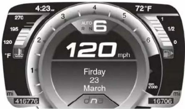
ElectronicVehicleInformationCenter(EVIC)
UNDERSTANDING YOUR INSTRUMENT PANEL 125
The Electronic Vehicle Information Center (EVIC) features a driver-interactive display that is located in the instrument cluster.
The EVIC consists of the following:
•Digital Speedometer
- Vehicle Info
• Fuel Economy Info
- Trip Info
- Screen Setup
- Vehicle Settings
The system allows the driver to select information by pushing the following buttons mounted on the instrument panel to the left of the steering column:
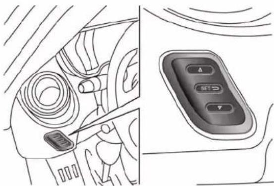
natural_image
Interior view of a car showing dashboard and control panel (no text or symbols)EVICControlButtons
-UPArrowButton
△ Push and release the UP arrow button to scroll upward through the main menu and sub-menus or to increase the displayed value. Outside of the menu, the UP arrow will adjust the brightness of the instrument panel.
126UNDERSTANDINGYOURINSTRUMENTPANEL
- DOWNArrowButton

Push and release the DOWN arrow button to scroll downward through the main menu and sub-menus or to decrease the displayed value. Outside of the menu, the DOWN arrow will adjust the brightness of the instrument panel.
- SET/BACKArrowButton
Push and release the SET/BACK arrow button to access/select the information screens or sub-menu screens of a main menu item. Push and hold the SET/BACK arrow button to return to the main menu from an info screen or sub-menu item.
ElectronicVehicleInformationCenter(EVIC) SetupMenu
The menu comprises a series of functions arranged in a cycle. Push the UP △ and DOWN ▽ buttons to access the different options and settings (setup).
The setup menu can be activated by pushing the SET/BACKbutton. Single push on the UP △ or DOWN ▽ buttons will scroll through the setup menu options. The menu includes the following functions:
- Menu
- Speed Buzzer
- Trip B/Data
- Set Time
- Set Date
- Autoclose
- Units
•Language - Buzzer Volume
•Service
• Daylights (D.R.L.) – If Equipped
- Exit Menu
SelectingAnOptionOfTheMainMenuWithout Submenu
- Briefly push the SET/BACKbutton to select the main menu option to set.
- Push the UP △ or DOWN button (by a single push) to select the new setting.
- Briefly push the SET/BACKbutton to store the new setting and go back to the main menu option previously selected.
SelectingAnOptionOfTheMainMenuWithSub-menu
- Briefly push the SET/BACK button to display the first submenu option.
UNDERSTANDING YOUR INSTRUMENT PANEL 127
- Push the UP △ or DOWN button (by a single push) to scroll through all the submenu options.
- Briefly push the SET/BACKbutton to select the displayed submenu option and to open the relevant setup menu.
- Push the UP △ or DOWN button (by a single push) to select the new setting for this submenu option.
- Briefly push the SET/BACKbutton to store the new setting and go back to the previously selected sub-menu option.
- Push and hold the SET/BACKbutton to return to the main menu (short hold) or the main screen (longer hold).
128 UNDERSTANDING YOUR INSTRUMENT PANEL
SpeedBuzzer(SpeedLimit)
With this function, it is possible to set the car speed limit (mph or km/h) to immediately alert the driver when the set limit is exceeded.
To set the speed limit, proceed as follows:
- Briefly push the SET/BACKbutton. The display will show the message (Speed Buzzer).
- Push and release the UP △ or DOWN button to select speed limit activation (On) or deactivation (Off).
- When the function is activated (On), briefly push the SET/BACK button to display the previously set speed. Pushing the UP △ or DOWN ▽ buttons selects the speed limit. Push SET/BACK to confirm selection.
NOTE: The setting can be increased or decreased by 5 mph or km/h each time the UP/DOWN button is pushed for speed settings above 20 mph (32 km/h). To increase or decrease the set speed rapidly, push and hold the UP/DOWN button. Save the setting by briefly pushing the button when you approach the required setting.
- Briefly push the SET/BACKbutton to go back to the menu screen, or push and hold the SET/BACKbutton (approximately one second) to go back to the main screen without storing the settings.
To cancel the setting, proceed as follows:
- Briefly push the SET/BACK button. "On" will display.
-
Push and release the DOWN ▽ button. "Off" will display.
-
Briefly push the SET/BACKbutton to go back to the menu screen, or push and hold the SET/BACK button (approximately one second) to go back to the main screen without storing the settings.
TripBActivation
Through this option, it is possible to activate (On) or deactivate (Off) the Trip B (partial trip) display.
For further information see "Trip Computer."
For activation / deactivation, proceed as follows:
-
Briefly push the SET/BACKbutton. "On" or "Off" will display in the EVIC (according to previous setting).
-
Push and release the UP △ or DOWN button to select the setting and once selected a beep will occur to signal the setting is saved.
UNDERSTANDING YOUR INSTRUMENT PANEL 129
- Briefly push the SET/BACKbutton to go back to the menu screen, or push and hold the SET/BACK button (approximately one second) to go back to the main screen without storing the settings.
SetTime
This function may be used to set the clock through two sub-menu items: "Time" and "Mode."
Proceed as follows:
-
Briefly push the SET/BACKbutton. The display will show the two sub-menu items "Time" and "Mode."
-
Push and release the UP △ or DOWN button to navigate the two sub-menu items.
-
Select the required option and then prush the SET/BACKbutton.
130UNDERSTANDINGYOURINSTRUMENTPANEL
- When accessing the "Time" sub-menu item, briefly push the SET/BACK button and "hours" will flash on the display.
- Push and release the UP △ or DOWN ▽ button for setting.
- Briefly push the SET/BACKbutton and "minutes" will flash on the display.
- Push and release the UP △ or DOWN ▽ button for setting.
NOTE:
- The setting will increase or decrease by one unit each time the UP △ or DOWN button is pushed.
Push and hold the button to increase/decrease the setting rapidly. Save the setting by briefly pushing the button when you approach the required setting. - Briefly push the SET/BACKbutton to return to the "Time" sub-function.
- When accessing the "Mode" submenu, briefly push the SET/BACKbutton. The previously set display format will flash on the display.
- Push and release the UP △ or DOWN ▽ button to select "24h" or "12h."
When you have selected the required settings, briefly push the SET/BACK button to go back to the Time, Mode
sub-menu screen, or push and hold the SET/BACK button (approximately one second) to go back to the main screen without storing the settings.
SetDate
This function may be used to set the date (day - month - year).
To change the date proceed as follows:
- Briefly push the SET/BACKbutton and "year" will flash on the display.
- Push and release the UP △ or DOWN ▽ button for setting.
- Briefly push the SET/BACKbutton and "month" will flash on the display.
- Push and release the UP △ or DOWN ▽ button for setting.
UNDERSTANDING YOUR INSTRUMENT PANEL
- Briefly push the SET/BACKbutton and "day" will flash on the display.
- Push and release the UP △ or DOWN button for setting.
NOTE: The setting will increase or decrease by one unit each time the UP △ or DOWN button is pushed.
Push and hold the UP or DOWN button to increase/decrease the setting rapidly. Save the setting by briefly pushing the button when you approach the required setting.
- Briefly push the SET/BACKbutton to go back to the menu screen, or push and hold the SET/BACK button (approximately one second) to go back to the main screen without storing the settings.
132UNDERSTANDINGYOURINSTRUMENTPANEL
Autoclose
With this function active, the doors will automatically lock at when the vehicle's speed exceeds 12 mph (20 km/h).
To change the setting proceed as follows:
- Briefly push the SET/BACK button "On" or "Off" will flash on the display (according to the previous setting).
- Push and release the UP △ or DOWN button for setting.
- Briefly push the SET/BACKbutton to go back to the menu screen, or push and hold the SET/BACK button (approximately one second) to go back to the main screen without storing the settings.
Units(SetUnits)
This function may be used to set the measurement unit in three submenus: "Distance," "Temperature" and "Fuel Economy."
To set the required unit, proceed as follows:
- Briefly push the SET/BACKbutton to display the three sub-menus.
- Push and release the UP △ or DOWN button to navigate the three sub-menus.
- Select the required sub-menu and then briefly push the SET/BACKbutton.
-
When accessing the "Distance" submenu: briefly push the SET/BACKbutton. Either "mi" or "km" will appear on the display (according to the previous setting).
-
Push and release the UP △ or DOWN ▽ button for setting.
- Briefly push the SET/BACKbutton to return to the sub-menu.
- When accessing the "Fuel Economy" submenu, briefly push the SET/BACK button. Either "mpg," "km/l" or "l/100km" will appear on the display (according to the previous setting).
If the distance unit set is "mi," the fuel economy unit will be displayed in "mpg."
If the distance unit set is "km," the fuel economy unit will be displayed in either km/l or l/100km. - Push and release the UP △ or DOWN ▽ button for setting.
- Briefly push the SET/BACKbutton to return to the sub-menu.
UNDERSTANDING YOUR INSTRUMENT PANEL 133
- When accessing the "Temperature" submenu: briefly push the SET/BACKbutton. Either "°F" or "°C" will appear on the display (according to the previous setting).
- Push and release the UP △ or DOWN ▽ button for setting.
- Briefly push the SET/BACKbutton to return to the sub-menu.
When you have made the required settings, briefly push the SET/BACK button to go back to the sub-menu screen, or push and hold the SET/BACKbutton (approximately one second) to go back to the main screen without storing the settings.
Language(SelectingTheLanguage)
The messages can be displayed in the following languages: Italian, English (USA), German, Portuguese, Spanish, French, Chinese, Russian, and Mexican.
134UNDERSTANDINGYOURINSTRUMENTPANEL
To set the required language, proceed as follows:
- Briefly push the SET/BACKbutton. The previously set "language" will flash on the display.
- Push and release the UP △ or DOWN ▽ button for setting.
- Briefly push the SET/BACKbutton to go back to the menu screen, or push and hold the SET/BACK button (approximately one second) to go back to the main screen without storing the settings.
BuzzerVolume(AdjustingTheFailure/Warning BuzzerVolume)
With this function the volume of the buzzer accompanying any failure/warning indication can be adjusted to one of eight volume levels.
To adjust the volume proceed as follows:
- Briefly push the SET/BACKbutton. The previously set volume "level" will flash on the display.
- Push and release the UP △ or DOWN button for setting.
- Briefly push the SET/BACKbutton to go back to the menu screen, or push and hold the SET/BACK button (approximately one second) to go back to the main screen without storing the settings.
UNDERSTANDING YOUR INSTRUMENT PANEL 135
Service(ScheduledServicing)—IfEquipped
With this function it is possible to view information on mileage intervals for servicing.

To obtain this information, proceed as follows:
Push the SET/BACKbutton briefly. The display shows the service interval in miles (mi) or kilometers (km) according to the previous setting (see the "Unit Of Measurement" paragraph).
Briefly push the SET/BACKbutton to go back to the menu screen or hold the button down to go back to the standard screen.
NOTE: The "Scheduled Servicing Plan" includes car maintenance at fixed intervals, refer to the "Maintenance" chapter. This message is displayed automatically along with the ⚫ warning light when the key is turned to MAR-ON - 1242 miles (2,000 km) before these deadlines and reappears every 124 miles (200 km). Below 124 miles (200 km) servicing indications are more frequent. The indication will appear in miles or kilometers according to the "Unit Of Measurement" settings. When the next scheduled service is approaching and the key is turned to MAR-ON, the word Service will appear on the display, followed by the number of miles or kilometers left. Contact a dedicated Alfa Romeo Dealership. The operations in the "Scheduled Servicing Plan" will be performed and the message will be ∇ reset.
136 UNDERSTANDING YOUR INSTRUMENT PANEL
DayLights—IfEquipped
This function may be used to activate / deactivate the Daytime Running Lamps.
Proceed as follows to switch this function on or off:
- Briefly push the SET/BACKbutton to display the three submenus.
- Briefly push the SET/BACKbutton. "On" or "Off" will flash on the display (according to previous setting).
- Push and release the UP △ or DOWN ▽ button for setting.
- Briefly push the SET/BACKbutton to go back to the menu screen, or push and hold the button (approximately one second) to go back to the main screen without storing the settings.
ExitMenu
This function closes the initial menu screen.
Briefly push the SET/BACKbutton to go back to the main screen.
Push and release the △ button to return to the first menu option (Speed Buzzer).
Push and releasethe button to return to the last menu option (Daylights).
ChangeEngineOilIndicatorSystem

Your vehicle is equipped with an engine oil indicator system. The “Change Engine Oil” mes- will flash in the EVIC display for approximately 10 ds and the Oil Pressure Warning Light will illumi- The “Change Engine Oil” message in the EVIC and I Pressure Warning Light will turn off after ap- nately 10 seconds.
UNDERSTANDING YOUR INSTRUMENT PANEL 137
ResetoftheOilChangeRemindermessageasfollows:
- Without pressing the brake pedal, cycle the ignition to the MAR/AVV position (do not start the engine).
- Press and hold the accelerator pedal.
- Press and release the brake pedal 6 times; with a 1 second pause between each press.
- After the 6th release of the brake pedal, pause 1 second and then release the accelerator pedal.
TripComputer
The Trip Computer is located in the instrument cluster. It features a driver-interactive display (displays information such as trip information, range, fuel consumption, average speed, and travel time).
TripButton
The TRIPbutton, located on the right steering column stalk, can be used to display and to reset the trip values.
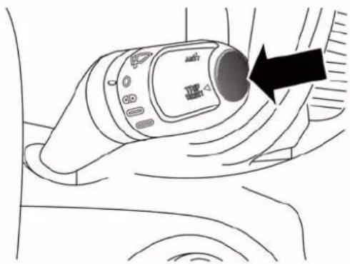
natural_image
Line drawing of a car interior showing a hand holding a digital camera with a circular button and an arrow pointing to the button (no text or symbols present)TripButton
- A short button push displays the different values.
- A long button push resets the system and then starts a new trip.
138UNDERSTANDINGYOURINSTRUMENTPANEL
TripFunctions
Both trip functions are resettable (reset — start of new trip).
"Trip A" can be used to display the figures relating to:
- Range
• Average Fuel Consumption - Travel Distance
- Current Fuel Consumption
• Average speed - Travel time
"Trip B" can be used to display the figures relating to:
• Average Fuel Consumption
- Travel Distance
• Average speed
- Travel time
NOTE: "TripB" functions maybe excluded (see "Trip BData"). "Range" and "Instantaneous consumption" cannot be reset.
NewTrip
To reset:
- Push and hold the TRIPbutton to reset the system manually.
- When the “Trip distance” reaches 9999.9 miles or kilometers or when the “Travel time” reaches 999.59 (999 hours and 59 minutes), the system is reset automatically.
- Disconnecting/Reconnecting the battery resets the system.
NOTE: If the reset operation occurs in the presence of the screens concerning Trip A or Trip B, only the information associated with Trip A or Trip B functions will be reset.
StartOfTripProcedure
With the ignition on, push and hold the TRIPbutton for over one second to reset.
ExitTrip
To exit the Trip function, wait until all the values have been displayed or hold the MENU button for longer than one second.
Briefly push and release the MENUbutton to go back to the menu screen or push and hold the MENU(approximately one second) to go back to the main screen without storing settings.
ValuesDisplayed
IndicationsOnDisplay
Each time a value is selected, the following information is shown in the EVIC:
- "Trip A" or "Trip B" location(s)
- Name, value and unit of measure of the selected value (e.g. "Range 520 mi").
140UNDERSTANDINGYOURINSTRUMENTPANEL
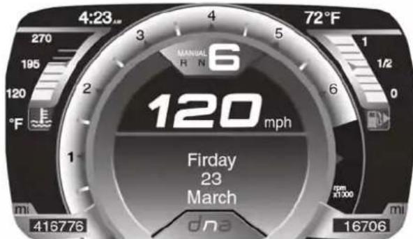
After a few seconds, the name of the selected value is replaced by the corresponding icon.
Range
This indicates the distance which may be traveled with the fuel remaining in the tank, assuming that driving conditions will not change. The message “----” will appear on the display in the following cases:
• Distance less than 30 miles (or 50 km).
- The vehicle is parked for a long time with the engine running.
NOTE: The range depends on several factors: driving style, type of route (freeway, residential, mountain roads, etc.), conditions of use of the car (load, tire pressure, etc.). Trip planning must take into account the above notes.
AverageFuelConsumption
This value shows the approximate average consumption since the last reset.
TravelDistance
This value shows the distance covered since the last reset.
CurrentFuelConsumption
This indicates the fuel consumption. The value is constantly updated. The message “----” will appear on the display if the car is parked with the engine running.
UNDERSTANDING YOUR INSTRUMENT PANEL 141
AverageSpeed
This value shows the vehicle's average speed as a function of the overall time elapsed since the last reset.
TravelTime
This value shows the time elapsed since the last reset.
TirePressureValues
This screen will display OK at each Tire Pressure Monitoring sensor. Refer to "Tire Pressure Monitoring System" in "Starting And Operating."
RADIOSYSTEM
The radio system consists of:
•Supply cables for radio, speakers and aerial;
• Radio;
- Aerial on front bumper;
- No. 2 tweeter speakers with 38mm diameter and No. 2 mid-woofer speakers with 130mm diameter, fitted on the doors.
For further information on radio functions and use, refer to the dedicated Supplement attached to the On-Board Documentation.
RADIOOPERATIONANDMOBILEPHONES
Under certain conditions, the mobile phone being on in your vehicle can cause erratic or noisy performance from your radio. This condition may be lessened or eliminated by relocating the mobile phone antenna. This condition is not harmful to the radio. If your radio performance does not satisfactorily “clear” by the repositioning of the antenna, it is recommended that the radio volume be turned down or off during mobile phone operation.
142UNDERSTANDINGYOURINSTRUMENTPANEL
GeneralInformation
This device complies with Part 15 of the FCC rules and RSS 210 of Industry Canada. Operation is subject to the following conditions:
- Changes or modifications not expressly approved by the party responsible for compliance could void the user's authority to operate the equipment.
• This device may not cause harmful interference. - This device must accept any interference received, including interference that may cause undesired operation.
HEATINGANDVENTILATION
ManualClimateControlsWithA/C
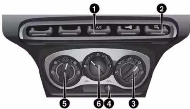
Heating/VentilationAndAirConditioningControls
The Heating/Ventilation And Air Conditioning Controls consist of a series of three rotary dials, a movable cursor and two on/off switches.
1.A/CButton
Press this button to engage the Air Conditioning. A light will illuminate when the Air Conditioning system is engaged.
MAXA/C
For maximum cooling, use the A/C and recirculation modes at the same time.
ECONOMYMODE
If economy mode is desired, press the A/C switch to turn OFF the A/C compressor. Then, rotate the temperature control to the desired temperature.
2. Demist/DefrostControl
Press and release the Demist/Defrost Control button to turn ON the heated outside mirrors. The Demist/Defrost feature automatically turns OFF after 20 minutes.
3.ModeControl
Rotate this control to change the system between Modes (Panel, Bi-Level, Floor, Mix, Defrost).
Panel- Air is directed through the outlets in the instrument panel. These outlets can be adjusted to direct airflow.
Bi-Level-Air is directed through the panel and floor outlets.
Floor- Air is directed through the floor outlets with a small amount flowing through the defrost and side window demister outlets.
144UNDERSTANDINGYOURINSTRUMENTPANEL
Mix - Air is directed through the floor, defrost, and side
window demister outlets. This setting works best in cold or snowy conditions that require extra heat to the windshield. This setting is good for maintaining comfort while reducing
moisture on the windshield.
4. Recirculation Control
Slide cursor to change the system between recirculation mode and outside air mode. Recirculation can be used when outside conditions such as smoke, odors, dust, or high humidity are present.
NOTE:
- Continuous use of the Recirculation mode may make the inside air stuffy and window fogging may occur. Extended use of this mode is not recommended.
- The use of the Recirculation mode in cold or damp weather could cause windows to fog on the inside,
because of moisture buildup inside the vehicle. Select the outside air position for maximum defogging.
5.TemperatureControl
Rotate this control to regulate the temperature of the air inside the passenger compartment. Rotating the dial counterclockwise into the blue area of the scale indicates cooler temperatures, while rotating clockwise into the red area indicates warmer temperatures.
6.BlowerControl
Rotate this control to regulate the amount of air forced through the ventilation system in any mode. The blower speed increases as you move the control clockwise from the "0" (OFF) position. There are four blower speeds.
Heating
To heat the passenger compartment, proceed as follows:
-
Rotate the Temperature Control to the red section.
-
Turn the Blower Control to the desired speed.
- Turn the Mode Control to 🖼️.
- Then operate the controls to maintain the desired comfort conditions.
NOTE:
- This air distribution allows the passenger compartment to be heated quickly.
- When the engine is cold, it takes a few minutes to achieve optimum passenger compartment heating.
FastDemisting/DefrostingOfWindshieldAndSideWindows
Proceed as follows:
- Rotate the Temperature Control to the red section.
- Turn the Blower Control to 4 (maximum fan speed).
UNDERSTANDING YOUR INSTRUMENT PANEL 145
- Turn the Mode Control to
- Move the Recirculation Control to ∞.
After demisting/defrosting, operate the controls as normal to restore the required comfort conditions.
NOTE: The climate control system is very useful for speeding up and maintaining demisting since it dehumidifies the air. Adjust the controls as described previously and switch on the climate control system by pressing the A/C button.
WindowDemisting
In the event of considerable external moisture and/or rain and/or large differences in temperature inside and outside the passenger compartment, perform the following preventive window demisting procedure:
- Move the Recirculation Control to ∞.
- Rotate the Temperature Control to the red section.
146UNDERSTANDINGYOURINSTRUMENTPANEL
- Turn the Blower Control to 2 (intermediate fan speed).
- Turn the Mode Control to 📋 with the possibility of moving it to position 🌐 if window misting does not occur.
Ventilation
To ventilate the passenger compartment properly, proceed as follows:
- Fully open the vents and direct them appropriately.
- Rotate the Temperature Control to the blue section.
- Move the Recirculation Control to ∞.
- Turn the Blower Control to the desired speed.
- Turn the Mode Control to ↗.
InternalAirRecirculationActivation
- Move the Recirculation Control to
It is advisable to switch the internal air recirculation on while standing in queues or in tunnels to prevent the introduction of polluted air.
Do not use the function for a long time, particularly if there are two people on board, to prevent the windows from misting.
NOTE: The internal air recirculation system makes it possible to reach the required heating or ventilation conditions more quickly. Do not use the internal air recirculation function on rainy/cold days to avoid the possibility of the windows misting.
ClimateControl
Proceed as follows:
-
Rotate the Temperature Control to the blue section.
-
Turn the Blower Control to 1 (1st fan speed). For rapid cooling, turn Blower Control to 4 (maximum fan speed).
- Move the Recirculation Control to 📄.
- Turn the Mode Control to ↗.
- Press the A/C button.
CoolingAdjustment
Proceed as follows:
- Move the Recirculation Control to ∞.
- Rotate the Temperature Control towards the red section to increase the temperature.
- Turn the Blower Control counterclockwise to reduce the fan speed.
DoorMirrorDemisting
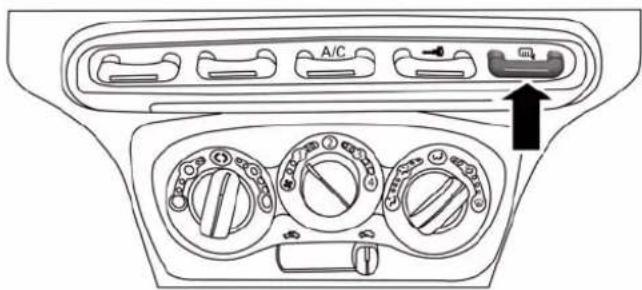
Demist/DefrostButton
- Press the 📄 button to activate this function.
- Press the 📄 button again to deactivate the function.
148UNDERSTANDINGYOURINSTRUMENTPANEL
Activation is indicated by the digital warning light on the display.
SystemMaintenance
In winter, the climate control system must be turned on at least once a month for about 10 minutes. Have the system inspected at an authorized dealer before the summer.
NOTE: The system uses R-1234yf and R134a coolant which does not pollute the environment in the event of accidental leakage. Under no circumstances should you use R-134a fluid which, in addition to being incompatible with the system's components, contributes greatly to the greenhouse effect.
□Automatic Transmission....152
□Normal Starting. 153
□Cold Weather Operation....153
□If Engine Fails To Start....153
□After Starting . . . . . . . . . . . . . . . . . . . . . . . . . . . . . . . . . . . . . . . . . . . . . . . . 154
□Turbo Charger "Cool Down"....154
■SIX-SPEED ALFA TWIN CLUTCH TRANSMISSION....154
□Using The Transmission....155
■ALFA DNA SYSTEM (DYNAMIC CAR CONTROL SYSTEM)....161
□Driving Modes....162
□System Failure....166
□Launch Control....166
■DRIVING ON SLIPPERY SURFACES....167
□Acceleration....167
□Traction....168
■DRIVING THROUGH WATER....168
□ Flowing/Rising Water .....169
150 STARTING ANDOPERATING
□Shallow Standing Water....169
■PARKING BRAKE....170
□System Intervention....175
□Electronic Brake Distribution System (EBD) . . .175
□Four-Wheel Anti-Lock Brake System (ABS) . . .175
□Cornering Brake Control System (CBC) . . . . . .177
□Drag Torque Control System (DTC) .....177
□AntiSlip Regulation System (ASR) .....177
□Hill Start Assist (HSA)....178
□Hydraulic Brake Assistant System (HBA) . . . 180
□Electronic Q2 System (E-Q2)....180
□Ready Alert Brake System (RAB)....181
■TIRE SAFETY INFORMATION .....181
□Tire Markings....181
□Tire Identification Number (TIN). . . . . . . . . . . . . .185
□Tire Terminology And Definitions....186
□Tire Loading And Tire Pressure .....188
■TIRES — GENERAL INFORMATION .....192
□Tire Pressure....192
□Tire Inflation Pressures .....193
☐Tire Pressures For High Speed Operation ....195
□Radial Ply Tires....195
□General Information....211
■FUEL REQUIREMENTS — 1.750 Turbo ..... 2 1 1
□Reformulated Gasoline....212
□ Gasoline/Oxygenate Blends .....212
□MMT In Gasoline....212
□ Materials Added To Fuel .....213
□ Fuel System Cautions. . . . . . . . . . . . . . . . . . . . . . . . . . . . . . . . . . . . . . . . . . . . . . . . . 213
□Carbon Monoxide Warnings .....214
■ADDING FUEL/SMART FUEL .....215
■TRAILER TOWING .....218
■RECREATIONAL TOWING (BEHIND MOTORHOME, ETC.)....218
□Towing This Vehicle Behind Another Vehicle . .218
Before starting your vehicle, adjust your seat, adjust both inside and outside mirrors, and fasten your seat belts.
WARNING!
- Neverleavechildrenaloneinavehicle,orwith accesstoanunlockedvehicle.
- Allowingchildrentobeinavehicleunattendedis dangerousforanumberofreasons.Achildor otherscouldbeseriouslyorfatallyinjured.Childrenshouldbewarnednottotouchtheparking brake,brakepedalorthetransmissiongearslector.
- DonotleavetheKeyFobinornearthevehicle(or inalocationaccessibletochildren).Achildcould operatepowerwindows,othercontrols,ormove thevehicle.
AutomaticTransmission
To start the engine press the brake pedal: the system engages NEUTRAL (N) automatically.
After the starting procedure, FIRST (1st) gear or REVERSE (R) can be engaged.
Irrespective of the mode selected (AUTO/MANUAL), to engage FIRST (1st) gear or REVERSE (R), it is necessary to press the brake pedal and press the 1 button on the transmission control panel (or the "+"steering wheel stalk) to engage FIRST (1st) gear or the R button to engage REVERSE (R).
When FIRST (1st) gear is engaged, the system sets itself to AUTO mode.
NEUTRAL (N) can be engaged again by pressing the N button with the brake pedal pressed.
When the 1, N or R buttons are pressed (or "+"steering wheel stalk is operated) without pressing the brake pedal, no gear change request is implemented by the system.
NOTE: REVERSE (R) cannot be engaged by pressing the "-"stalk on the steering wheel.
NormalStarting
NOTE: Normal starting of either a cold or a warm engine is obtained without pumping or pressing the accelerator pedal.
Turn the ignition switch to the AVV/ACC (START) position and release it when the engine starts. If the engine fails to start within 10 seconds, turn the ignition switch to the STOP (OFF/LOCK) position, wait 10 to 15 seconds, then repeat the "Normal Starting" procedure.
ColdWeatherOperation
Your engine is designed to operate at temperatures as low as 0^ F (-18°C).
NOTE: Use of the recommended SAE 5W-40 Synthetic oil and adhering to the prescribed oil change intervals is important to prevent engine damage and ensure satisfactory starting in cold conditions.
IfEngineFailsToStart
WARNING!
Neverpourfuelorotherflammableliquidsintothe throttlebodyairinletopeninginanattempttostart thevehicle. Thiscouldresultinaflashfirecausing seriouspersonalinjury.
CAUTION!
- Donotattempttopushortowyourvehicletogetit started. VehiclesequippedwithaAlfaTwinClutch Transmissioncannotbestartedthisway.Unburned fuelcouldenterthecatalyticconverterandoncethe enginehasstarted,igniteanddamagetheconverter andvehicle.
- Topreventdamagetothestarter, donotcontinuouslycranktheengineformorethan15secondsat atime. Wait10to15secondsbeforetryingagain.
AfterStarting
The idle speed is controlled automatically and it will decrease as the engine warms up.
TurboCharger“CoolDown”
This vehicle is equipped with an after-run pump to cool the turbocharger after the engine is shut off. Depending on the type of driving and the amount of cargo, the pump will run for up to five minutes after the engine has been shut off to circulate coolant through the turbocharger.
Although the pump is rubber-mounted for quiet operation, it is normal to hear it running during this time.
SIX-SPEEDALFATWINCLUTCHTRANSMISSION
WARNING!
- It is dangerous to shift out of NEUTRAL if the enginespeedish higher than idlespeed. If your foot is not firmly pressing the brake pedal, the vehicle could accelerate quickly forward or in reverse. You could lose control of the vehicle and hits someone or something. Only shift into gear when the engine is idling normally and your foot is firmly pressing the brake pedal.
(Continued)
WARNING!(Continued)
- Unintendedmovementofvehiclecouldinjure thoseinornearthevehicle.Aswithallvehicles, youshouldneverexitavehiclewhiletheengineis running.Beforeexitingthevehicle,alwaysapply theparkingbrake,shiftthetransmissionintogear, turntheengineOFF,andremovetheignitionkey.
- Whenleavingthevehicle,alwaysremovetheignitionkeyandlockyourvehicle.
- Neverleavechildrenaloneinavehicle,orwith accesstoun unlocked vehicle. Allowingchildrento beinavehicleunattendedisdangerousfora numberofreasons.Achildorotherscouldbe seriouslyorfatallyinjured.Childrenshouldbe warnednottotouchtheparkingbrake,brakepedal orthetransmissiongearselector.
(Continued)
WARNING!(Continued)
- Donotleavetheignitionkeyinornearthevehicle (orinalocationaccessibletochildren).Achild couldoperatepowerwindows,othercontrols,or movethevehicle.
UsingTheTransmission
This vehicle is equipped with a Six-Speed Alfa Twin Clutch transmission with steering wheel mounted shift paddles.
When the ignition is in the OFF position, the transmission controls (shift paddles on the steering wheel, and gear selector buttons on the center console) are disabled.
When the key is turned to the ON position, the current transmission gear will be displayed in the instrument cluster, along with the "AUTO" indicator. This indicates the transmission is in Automatic mode.
OperatingModes
The transmission has two normal operating modes (except when the "Race" mode is selected on the DNA switch):
MANUAL mode in which the driver must shift gears manually (using the steering wheel mounted shift paddles).
Automatic (AUTO) mode, in which the system shifts between all forward gears automatically.
When the "Race" mode is selected via the DNA selector, the only allowed transmission operating mode is MANUAL.
MANUALMode
In this operating mode, the driver is responsible for choosing the best gear to engage, depending on the car operating conditions. The current gear is displayed in the instrument cluster.
To activate/deactivate MANUAL mode, press the A/M button on the center console when the transmission is in any forward gear.
Use the “+” shift paddle to engage a higher gear, or the “-” paddle to engage a lower gear.
If a requested gear shift is not allowed (typically, because it would cause engine overspeed or lugging), an audible signal will sound and the transmission will remain in the existing gear.
The transmission will automatically downshift during closed-throttle decelerations, to prevent engine lugging. When coming to a stop, the transmission will automatically select FIRST (1st) gear. The driver must manually upshift the transmission (by tapping the + shift paddle) as the vehicle accelerates.
NOTE: To provide better comfort, the transmission will up-shift to the next available gear if the engine speed limit is reached. This feature is only available in NATURAL and ALL WEATHER Modes.
AUTOMode
In AUTO mode the transmission shifts gears automatically depending on vehicle speed, engine RPM, and accelerator pedal position.
AUTO is the default operating mode at startup. When in AUTO mode, "AUTO" appears in the instrument cluster, adjacent to the current gear display.
To toggle between AUTO and MANUAL modes, press the A/M button on the center console.
AcceleratingFromAStop
FIRST (1st) and REVERSE (R) can only be engaged (at a stop) by pressing "1" or "R" when the brake pedal is pressed.
To drive, press the brake pedal, and select 1 (One) or R (Reverse) by pressing "1" or "R" using the transmission
gear selector buttons on the center console. Then release the brake pedal and smoothly press the accelerator pedal.
NOTE: When starting on a fairly steep incline, it may be advisable to engage the parking brake.
The vehicle can only be launched (from a stop) in FIRST (1st) or REVERSE (R). SECOND (2nd) gear (or higher) cannot be engaged when the vehicle is stationary.
FIRST (1st) and REVERSE (R) gears can only be engaged at vehicle speeds below 2 mph (3 km/h). At speeds below 6 mph (10 km/h), attempts to shift from 1st to R (or R to 1st) will only be allowed if the vehicle speed drops below the 2 mph (3 km/h) threshold within three seconds of the request; otherwise, the transmission will shift to NEUTRAL (N). The driver should then repeat the request for 1st or R once the vehicle has come to a stop.
ShiftPaddles
In MANUAL mode, the steering wheel mounted shift paddles (labeled + and -) control the transmission shifting.
Tapping the (+) paddle will upshift the transmission to the next higher gear, while tapping the (-) paddle will downshift to the next lower gear. The current gear is displayed in the instrument cluster. If a requested shift would cause engine lugging or overspeed, that request will be ignored.
In AUTO mode, tapping a shift paddle will temporarily place the transmission in MANUAL mode, and execute the requested upshift or downshift (if allowable). The transmission will then return to AUTO mode after a brief interval. Pressing a shift paddle will only shift the transmission one gear at a time. Holding a paddle
depressed will not command multiple shifts; the paddle must be pressed multiple times in succession to generate multiple shifts.
If the brake pedal is not depressed (and the car is stationary for a period of time), the transmission will automatically engage NEUTRAL (N).
Neutral(N)
Use this range when the vehicle is standing for prolonged periods with the engine running. Always apply the parking brake if you must leave the vehicle.
At engine startup, the transmission will automatically select NEUTRAL (N) and AUTO mode. The brake pedal must be pressed when starting the engine.
To select NEUTRAL (N) when the vehicle is stationary, turn the ignition key to the MAR-ON position (engine running or not), press the brake pedal, and press the N button on the transmission gear selector.
When the vehicle is moving (with ignition ON), pressing the NEUTRAL (N) button will engage N, regardless of whether the brake pedal is pressed.
WARNING!
DonotcoastinNEUTRALandneverturnoffthe ignitiontocoastdownahill.Theseareunsafe practicesthatlimityourresponsetochangingtraffic orroadconditions.Youmightlosecontrolofthe vehicleandhaveacollision.
With car in motion, to engage a gear from the NEUTRAL (N) position, press the 1 button on the transmission control panel (it is not necessary to press the brake pedal) the transmission will immediately engage the correct gear according to the car's speed.
If the vehicle is stationary with the engine running and FIRST (1st) gear or REVERSE (R) engaged, the system activates an acoustic signal and automatically places the transmission in NEUTRAL (N) when:
The accelerator and/or brake pedal are not operated for at least three minutes.
The brake pedal is pressed for longer than 10 minutes.
The driver's door is opened and the accelerator pedal or the brake pedal are not operated for at least one and a half seconds.
A fault has been detected in the transmission.
ParkingTheVehicle
When parking and leaving the car, proceed as follows:
-
Press the brake pedal and shift the transmission into First (1st).
-
Stop the engine and firmly engage the parking brake.
- Release the brake pedal.
When parking on an incline, turn the front wheels toward the curb on a downhill slope and away from the curb on an uphill slope. Always chock the wheels when parking on steep grades.
GeneralNotes
When the vehicle is stopped and in gear, always keep the brake pedal pressed until you decide to set off, then release the brake and accelerate gradually.
During prolonged stops with the engine running, it is advisable to keep the transmission in NEUTRAL (N).
When stopped on an incline, always hold the vehicle in place using the brakes. On steep inclines, Hill Start Assist (HSA) will temporarily hold the car in position when the brake pedal is released. If the accelerator pedal is not
applied after a short time, the car will roll back. Either reapply the brake (to hold the vehicle) or press the accelerator to climb the hill.
Only shift between FIRST (1st) and REVERSE (R) when completely stopped, with the brake pedal pressed.
When necessary, it is possible to engage FIRST (1st), REVERSE (R) or NEUTRAL (N) with the engine off, the key at MAR-ON and the brake pressed. In this case, wait at least five seconds between one gear change and the next, in order to safeguard the operation of the hydraulic system, and the pump in particular.
For uphill departures, it is advisable to accelerate gradually but fully immediately after releasing the parking brake or the brake pedal; this allows the engine to temporarily increase the number of revs and tackle the steepest gradients with more torque at the wheels.
This vehicle is equipped with a "Alfa DNA" system lever (located on the center console). There are four modes of operation to be selected according to driving style and road conditions:
Dynamic (This mode alters the transmission's automatic shift schedule for sportier driving [D]).
Natural (mode for driving in normal conditions [N]).
All Weather (mode for driving in poor grip conditions, such as rain and snow [A]).
Race (sports driving mode [D]).
This also acts on the dynamic car control systems (engine, gearbox/transmission, ESC system).
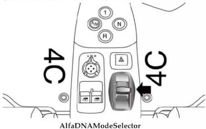
DrivingModes
The Alfa DNA system lever will always return to the center position after use.
The selected driving mode is indicated by the corresponding LED switching in the panel and by an indication on the display.
DynamicMode
Activation
Move the Alfa DNA system lever upwards (to the letter "D") and hold in this position for half a second, until the corresponding LED lights up and the Dynamic mode activation indicator appears on the display.
When Dynamic mode is activated, the turbocharger pressure and engine oil temperature screen is displayed automatically. When released, the Alfa DNA system lever will return to the central position.
NOTE: Dynamic Mode will be inhibited until the vehicle has accumulated 155 miles (250 km).
ElectronicStabilityControl(ESC)andAnti-SlipRegulation(ASR)systems:
The ESC and ASR system ensures more enjoyable, sportier driving while guaranteeing the stability of the car.
ElectronicQ2system:
The system increases vehicle stability while accelerating on bends, improving the agility of the car.
EngineAndGearbox/Transmission:
The system adjusts the transmission shift calibration for sportier shifting.
NOTE: In Dynamic mode, the engine response to the accelerator pedal position increases considerably. Consequently, driving is less fluid and comfortable.
Deactivation
To deactivate Dynamic mode and return to Natural, move lever downwards (to letter "A") and keep it in this position for half a second.
The LED corresponding to Natural mode will light up and the Natural mode activation indication will appear on the display.
RaceMode
Activation
Move the Alfa DNA system lever upwards (to the letter "D") and hold in this position for five seconds, until the Race mode activation indicator appears on the display.
When Race mode is activated, the longitudinal/lateral accelerometer indicator screen (G-meter information) is displayed automatically. This considers gravitational acceleration (G).
ElectronicStabilityControl(ESC)andAnti-SlipRegulation(ASR)systems:
These systems are deactivated in order to ensure the fullest sensation of sport, leaving the driver in full control of the vehicle. When the vehicle is in unstable conditions, the ESC reactivates automatically when the brake pedal is pressed until the ABS intervenes, thus returning the vehicle to stable conditions. To deactivate the ESC and ASR systems reactivate Race mode.
ElectronicQ2system:
The system increases vehicle stability while accelerating on bends, improving the agility of the car.
EngineAndGearbox/Transmission:
The system adjusts the transmission shift calibration for sportier shifting.
NOTE: In Race mode, the sensitivity of the accelerator pedal increases considerably. Consequently, driving is less fluid and comfortable.
In Race mode the transmission only works in MANUAL mode. Refer to the "Manual Operation" in "Starting and Operating" for further information.
Deactivation
To deactivate Race mode and return to Dynamic mode, move the Alfa DNA system lever downwards (to letter "A") and keep it in this position for half a second.
The LED corresponding to Dynamic mode will light up and the Dynamic mode activation indication will appear on the display.
ElectronicStabilityControl(ESC)andAnti-SlipRegulation(ASR)systems:
ESC and ASR system thresholds are aimed at providing comfort and safety in normal grip and driving conditions.
ElectronicQ2system:
The system is calibrated to ensure the best driving comfort.
EngineAndGearbox/Transmission:
Standard response shifting.
AllWeatherMode
Activation
Move the Alfa DNA system lever downwards (to the letter "A") and hold in this position for half a second,
until the corresponding LED lights up and the All Weather mode activation indicator appears on the display.
ElectronicStabilityControl(ESC)andAnti-SlipRegulation(ASR)systems:
ESC and ASR system thresholds are aimed at ensuring maximum safety in low-grip driving conditions. It is advisable to select All Weather mode in the presence of low-grip road surfaces.
ElectronicQ2System:
The system is deactivated.
EngineAndGearbox/Transmission:
Standard response shifting.
To deactivate All Weather mode and return to Natural mode, move the Alfa DNA system lever upwards (to letter "D") and keep it in this position for half a second.
NOTE:
When the engine is next started, All weather mode or Natural mode will be retained when the car is restarted.
When the engine is next started, Race mode or Dynamic mode previously selected is not retained. The system will reactivate in Natural mode.
It is not possible to go directly from Dynamic mode to All Weather mode and vice versa. You must always first go back to Natural mode and then select the other mode.
SystemFailure
In the event of system failure or a fault with the gear selector, no driving modes can be selected.
The display will become grey (same screen as "Natural" mode) but without an indication of the Alfa DNA setting. The display will also show a warning message.
Please contact your authorized dealer for service.
LaunchControl
The Launch Control strategy permits high-performance acceleration.
This strategy can be activated with vehicle at a standstill, Race mode selected and FIRST (1st) gear engaged.
The sequence of operations to perform is as follows:
- Press the brake pedal and hold it down.
-
Press the accelerator pedal and hold it down.
-
Press the "-"paddle behind the steering wheel.
When the brake pedal is released, the car will start with maximum acceleration. Despite the MANUAL mode, the vehicle will automatically shift the gear to guarantee maximum acceleration, once the correct shifting speed has been reached.
WARNING!
LaunchControlisintendedforoff-highwayoroff-roaduseonlyandshouldnotbeusedonanypublic roadways.UseLaunchControlonlyinacontrolled anddrytrackenvironment;withinthelimitsofthe law.ActualLaunchControlperformancemaychange dependingonthesurfaceandcurrenttractionconditions.Thecapabilitiesofthevehicleasmeasuredby theperformancepagesmustneverbeexploitedina recklessordangerousmanner,whichcanjeopardize
WARNING!(Continued)
theuser'ssafetyorthesafetyofothers.Onlyasafe, attentive,andskillfuldrivercanpreventaccidents. Failuretofollowthiswarningmayresultinserious injuryordeath.
To discontinue the strategy, simply interrupt the above sequence of operations or release the accelerator pedal.
DRIVINGONSLIPPERYSURFACES
Acceleration
Rapid acceleration on snow covered, wet, or other slippery surfaces may cause the driving wheels to pull erratically to the right or left. This phenomenon occurs when there is a difference in the surface traction under the rear (driving) wheels.
(Continued)
Rapidacceleration on slipperysurfaces is dangerous. Unequaltraction can cause sudden pulling of therear wheels. You could lose control of the vehicle and possibly have a collision. Accelerates slowly and carefully whenever there is likely to be poor traction (ice, snow, wet mud, looses and, etc.).
Traction
When driving on wet or slushy roads, it is possible for a wedge of water to build up between the tire and road surface. This is known as hydroplaning and may cause partial or complete loss of vehicle control and stopping ability. To reduce this possibility, the following precautions should be observed:
- Slow down during rainstorms or when the roads are slushy.
- Slow down if the road has standing water or puddles.
- Replace tires when tread wear indicators first become visible.
- Keep tires properly inflated.
- Maintain sufficient distance between your vehicle and the vehicle in front of you to avoid a collision in a sudden stop.
Your vehicle may be equipped with a Limited Slip Differential (LSD) that reduces, but does not eliminate, the amount of wheel slip across a given axle for improved handling.
DRIVINGTHROUGHWATER
Driving through water more than a few inches/centimeters deep will require extra caution to ensure safety and prevent damage to your vehicle.
Flowing/RisingWater
WARNING!
Donotdriveonoracrossaroadorpathwherewater isflowingand/orrising(asinstormrun-off).Flowingwatercanwearawaytheroadorpath'ssurface andcauseyourvehicletosinkintodeeperwater. Furthermore,flowingand/orrisingwatercancarry yourvehicleawaysswiftly.Failuretofollowthis warningmayresultininjuriesthatareseriousor fataltoyou,yourpassengers,andothersaroundyou.
ShallowStandingWater
Although your vehicle is capable of driving through shallow standing water, consider the following Cautions and Warnings before doing so.
WARNING!
- Drivingthroughstandingwaterlimitsyourvehicle'stractioncapabilities.Donotexceed5mph (8km/h)whendrivingthroughstandingwater.
- Drivingthroughstandingwaterlimitsyourvehicle'sbrakingcapabilities,whichincreasesstoppingdistances.Therefore,afterdrivingthroughstandingwater,driveslowlyandlightlypressonthebrakepedalseveraltimestodrythebrakes.
- Failuretofollowthesewarningsmayresultin injuriesthatareseriousorfataltoyou,yourpassengers,andothersaroundyou.
CAUTION!
- Alwayscheckthedepthofthestandingwater beforedrivingthroughit.Neverdrivethrough
(Continued)
CAUTION!(Continued)
standingwaterthatisdeeperthanthebottomof thetirerimsmountedonthevehicle.
- Determinetheconditionoftheroadorthepath thatisunderwaterandifthereareanyobstaclesin thewaybeforedrivingthroughthestandingwater.
- Donotexceed5mph(8km/h)whendriving throughstandingwater.Thiswillminimizewave effects.
- Drivingthroughstandingwatermaycausedamage toyourvehicle'sdrivetraincomponents.Always inspectyourvehicle'sfluids(i.e.,engineoil,transmission,axle,etc.)forsignsofcontamination(i.e., fluidthatismilkyorfoamyinappearance)after drivingthroughstandingwater.Donotcontinueto operatethevehicleifanyfluidappearscontaminated,asthismayresultinfurtherdamage.Such
CAUTION!(Continued)
damageisnotcoveredbytheNewVehicleLimited Warranty.
- Gettingwaterinsideyourvehicle'senginecan causeittolockupandstallout,andcauseserious internaldamagetotheengine.Suchdamageisnot coveredbytheNewVehicleLimitedWarranty.
PARKINGBRAKE
Before leaving the vehicle, make sure that the parking brake is fully applied. Also, be certain to leave manual transmission in REVERSE (R) or FIRST (1st) gear.
The parking brake lever is located in the central tunnel. To apply the parking brake, pull the parking brake lever up as firmly as possible. To release the parking brake, pull the parking brake lever up slightly, press the center button, then lower the parking brake lever completely.
natural_image
Interior view of a car dashboard and steering wheel (no text or symbols visible)ParkingBrakeLever
When the parking brake is applied with the ignition switch in the MAR (ACC/ON/RUN) position, the Brake Warning Light in the instrument cluster will illuminate.
When parking on a hill, it is important to turn the front wheels toward the curb on a downhill grade and away from the curb on an uphill grade. The parking brake
should always be applied whenever the driver is not in the vehicle.
WARNING!
- Neverleavechildrenaloneinavehicle,orwith accesstoanunlockedvehicle.
- Allowingchildrentobeinavehicleunattendedis dangerousforanumberofreasons.Achildor otherscouldbeseriouslyorfatallyinjured.Childrenshouldbewarnednottotouchtheparking brake,brakepedalorthetransmissiongearselector.
- DonotleavetheKeyFobinormearthevehicleor inalocationaccessibletochildren.Achildcould operatepowerwindows,othercontrols,ormove thevehicle.
(Continued)
WARNING!(Continued)
- Besuretheparkingbrakeisfullydisengaged beforedriving;failuretodosocanleadtobrake failureandacollision.
- Alwaysfullyapplytheparkingbrakewhenleavingyourvehicle,oritmayrollandcausedamageor injury. Also becertaintoleaveamanualtransmissioninREVERSEorFIRST(1st)gear.Failuretodo somayallowthevehicletorollandcausedamage orinjury.
CAUTION!
If the Brake Warning Lightremainson with the parkingbrakereleased, abrakesystemmalfunction is indicated. Havethebrakesystemserviced by an authorized dealer immediately.
BRAKESYSTEM
Your vehicle is equipped with dual hydraulic brake systems. If either of the two hydraulic systems loses normal capability, the remaining system will still function. However, there will be some loss of overall braking effectiveness. You may notice increased pedal travel during application, greater pedal force required to slow or stop, and potential activation of the “Brake System Warning Light.”
In the event power assist is lost for any reason (i.e., repeated brake applications with the engine off) the brakes will still function. However, the effort required to brake the vehicle will be much greater than that required with the power system operating.
ESC(ELECTRONICSTABILITYCONTROL) SYSTEM
The ESC system improves the directional control and stability of the vehicle in various driving conditions.
The ESC system corrects the car's understeer and oversteer, distributing the brake force on the appropriate wheels. The torque supplied by the engine can also be reduced in order to maintain control of the car.
WARNING!
- ElectronicStabilityControl(ESC) cannot prevent thenaturallawsofphysicsfromactingonthe vehicle,norcanitincreasethetractionaffordedby prevailingroadconditions.ESC cannot prevent all collisions,includingthoseresultingfromexcessive speedinturns,drivingonveryslippery surfaces,or
WARNING!(Continued)
hydroplaning.ESCalsocannotpreventcollisions resultingfromlossofvehiclecontrolduetoinappropriatedriverinputfortheconditions.Onlya safe,attentive,andskillfuldrivercanpreventcollisions.ThecapabilitiesofanESCequippedvehiclemustneverbeexploitedinarecklessor dangerousmannerwhichcouldjeopardizetheuser'ssafetyorthesafetyofothers.
- Vehiclemodifications, or failure to properly maintain your vehicle, may change the handling characteristics of your vehicle, and may negatively affect the performance of the ESC system. Changesto the steering system, suspension, braking system, tire type and size or wheels size may adversely affect
(Continued)
(Continued)
ESCperformance.Improperlyinflatedandun-evenlyworntiresmayalsodegradeESCperformance.Anyvehiclemodificationorpoorvehicle maintenance that reduce the effectiveness of the ESCsystemcan increase risk of loss of vehicle control, vehiclerollover, personal injury and death.
The ESC system uses sensors installed on the car to determine the trajectory that the driver intends to follow and compares it with the car's effective trajectory. When the real trajectory deviates from the desired trajectory, the ESC system intervenes to counter the car's understeer or oversteer.
•Oversteer: occurs when the vehicle is turning more than it should according to the angle of the steering wheel.
- Understeer: occurs when the vehicle is turning less than it should according to the angle of the steering wheel.
This vehicle's advanced electronic brake control system also includes: Electronic Brake Distribution (EBD), Anti-Lock Brake System (ABS), Cornering Brake Control System (CBC), Drag Torque Control System (DTC), AntiSlip Regulation System (ASR), Hill Start Assist (HSA), Hydraulic Brake Assistant System (HBA), ELECTRONIC Q2 system (E-Q2) and Ready Alert Brake (RAB). All of the systems work together to enhance vehicle stability and control in various driving conditions, and are commonly referred to as ESC.
SystemActivation
The ESC system activates automatically when the engine is started and can only be deactivated by selecting "Race" mode. Refer to the "Six-Speed Alfa Twin Clutch Transmission" in this section for further information.
SystemIntervention
This is indicated by the flashing of the warning light on the instrument panel, to inform the driver that the car is in critical stability and grip conditions.
ElectronicBrakeDistributionSystem(EBD)
The EBD system is an integral part of the ESC system and intervenes during braking, distributing the brake force optimally between front and rear wheels.
This guarantees greater braking stability for the vehicle, preventing sudden locking of the rear wheels and the consequent instability of the vehicle.
Four-WheelAnti-LockBrakeSystem(ABS)
The Four-Wheel ABS is designed to aid the driver in maintaining vehicle control under adverse braking conditions. The system operates with a separate computer to modulate hydraulic pressure, to prevent wheel lock-up and to help avoid skidding on slippery surfaces.
The system's pump motor runs during an ABS stop to provide regulated hydraulic pressure. The pump motor makes a low humming noise during operation, which is normal.
The ABS includes an amber ABS Warning Light. When the light is illuminated, the ABS is not functioning. The system reverts to standard non-anti-lock brakes. Turning the ignition Off and On again may reset the ABS if the fault detected was only momentary.
WARNING!
- WhentheABSintervenesandyoufeelthebrake pedalpulsating, donotreducethepressure, but holditdownfirmly and confidently; indoingso youwillbrakeinthestshortestdistancepossible, dependingon the current road conditions.
(Continued)
WARNING!(Continued)
- Formaximumefficiencyofthebrakingsystem,a bedding-inperiodofabout311miles(500km)is required:duringthisperioditisadvisabletoavoid sharp,repeatedandprolongedbraking.
- IftheABSintervenes, this indicates that the grip of the tires on theroad is near its limit: you must slowdown to as speed compatible with the available grip.
- The ABScan'toverrulethenaturallawsofphysics, andcan'tincreasethegripavailableaccordingto theconditionoftheroad.
- The ABScannotpreventaccidents, including those duetoexcessivespeedoncorners, driving on low-gripsurfacesoraquaplaning.
- The capability of the ABS must never be tested irresponsibly and dangerously, insuchawayasto
WARNING!(Continued)
compromisepersonalsafetyandthesafetyofothers.
- ForthecorrectoperationoftheABS, thetiresmust of necessitybethesamemakeandtypeonall wheels, imperfectconditionand, aboveall, ofthe prescribedtypeanddimensions.
When you are in a severe braking condition involving the use of the ABS, you will experience some pedal drop as the vehicle comes to a stop. This is the result of the system reverting to the base brake system.
Engagement of the ABS may be accompanied by a pulsing sensation. You may also hear a clicking noise. These occurrences are normal and indicate that the system is functioning properly.
SystemIntervention
A slight pulsing of the brake pedal and noise indicates the intervention of the ABS: this is completely normal when the system intervenes.
CorneringBrakeControlSystem(CBC)
The system acts when braking on corners, optimizing the distribution of brake pressure on the four wheels: the system prevents the wheels on the inside of the corner (less affected by the weight of the car) from locking, ensuring better stability and direction for the car.
DragTorqueControlSystem(DTC)
This is an integral part of the ESC system and intervenes in the event of sudden downshifting, or during braking when the ABS intervenes, restoring torque to the engine and thus preventing excessive drag at the drive wheels, which may lead the wheels to lock and a loss of car stability, above all in low-grip conditions.
AntiSlipRegulationSystem(ASR)
WARNING!
- ElectronicStabilityControl(ESC) cannot prevent thenaturallawsofphysicsfromactingonthe vehicle,norcanitincreasethetractionaffordedby prevailingroadconditions.ESC cannot prevent all collisions,includingthoseresultingfromexcessive speedinturns,drivingonveryslippery surfaces,or hydroplaning.ESCalsocannotpreventcollisions resulting from lossofvehiclecontrolduetoinappropriatedriverinputforthe conditions.Onlya safe,attentive,andskillfuldrivercanpreventcollisions.The capabilities of an ESC equipped vehicle must never be exploited in arecklessor dangerous manner which could jeopardize the user's safety or the safety of others.
(Continued)
WARNING!(Continued)
- Vehiclemodifications, or failure to properly maintain your vehicle, may change the handling characteristics of your vehicle, and may negatively affect the performance of the ESC system. Changesthe steering system, suspension, braking system, tire type and size or wheels is easy to adversely affect ESC performance. Improperly inflated and unevenly worntires may also degrade ESC performance. Any vehicle modification or poor vehicle maintenance that reduces the effectiveness of the ESC system can increase risk of loss of vehicle control, vehiclerollover, personal injury and death.
This is an integral part of the ESC system and automatically operates in the event of one or both drive wheels slipping, loss of grip on wet roads (hydroplaning) and acceleration on slippery, snowy or icy roads, etc.
Depending on the slipping conditions, two different control systems are activated:
- If the slipping involves both drive wheels, the ASR system intervenes, reducing the power transmitted by the engine.
- If the slipping only involves one of the drive wheels, it also intervenes automatically, braking the wheel that is slipping.
SystemIntervention
This is indicated by the flashing of the warning light on the instrument panel, to inform the driver that the car is in critical stability and grip conditions.
HillStartAssist(HSA)
This is an integral part of the ESC system and facilitates starting on slopes, activating automatically in the following cases:
- Uphill: car stationary on a road with a gradient higher than 5%, engine running, brake pressed and transmission in neutral (N) or gear other than reverse engaged.
- Downhill: car stationary on a road with a gradient higher than 5% , engine running, brake pressed and reverse (R) gear engaged.
When setting off, the ESC system control unit maintains the braking pressure on the wheels until the engine torque necessary for starting is reached, or in any case for a maximum of two seconds, allowing your right foot to be moved easily from the brake pedal to the accelerator.
When the two seconds have elapsed, without starting, the system is automatically deactivated, gradually releasing the braking pressure. During this release stage, the typical brake disengagement noise, indicating that the car is going to move imminently, can be heard.
NOTE:
- HSA is not a parking brake; therefore, never leave the vehicle without having engaged the parking brake, turned the engine off and engaged first gear, so that the vehicle is parked in safe conditions.
- There may be situations on small gradients (less than 8% ), with vehicle laden, in which the Hill Holder system may not activate, causing a slight reversing motion and increasing the risk of collision with another vehicle or object. The driver is, in any case, responsible for safe driving.
HydraulicBrakeAssistantSystem(HBA)
WARNING!
- TheHBAsystemcan'toverrulethenaturallawsof physics, and can'tincrease the grip available according to the condition of the road.
- TheHBAsystemcannotpreventaccidents,includingthoseduetoexcessivespeedoncorners,drivingonlow-gripsurfacesoraquaplaning.
- ThecapabilityoftheHBAsystemmustneverbe testedirresponsiblyanddangerously,insucha wayastocompromisethesafetyofthedriver,the otheroccupantsofthecaroranyotherroaduser.
The HBA system is designed to improve the car's braking capacity during emergency braking. The system detects emergency braking by monitoring the speed and force with which the brake pedal is pressed, and consequently applies the optimal brake pressure. This can reduce the braking distance, the HBA system therefore completes the ABS.
Maximum assistance from the HBA system is obtained pressing the brake pedal very quickly. In addition, the brake pedal should be pressed continuously during braking, avoiding intermittent presses, to get the most out of the system.
Do not reduce pressure on the brake pedal until braking is no longer necessary.
The HBA system is deactivated when the brake pedal is released.
ElectronicQ2System(E-Q2)
The "Electronic Q2" system intervenes during acceleration on corners, braking the inner drive wheel and thus increasing the traction of the outer wheel (which bears more of the car's weight): the torque is thus distributed
optimally between the drive wheels in accordance with the driving conditions and road surface, permitting particularly effective, sporty driving.
ReadyAlertBrakeSystem(RAB)
This function activates automatically if the accelerator pedal is released rapidly, reducing the brake pad travel (both at front and back), with the aim of preparing the braking system and enhancing its responsiveness, thus reducing the stopping distance in the event of subsequent braking.
TIRESAFETYINFORMATION
TireMarkings
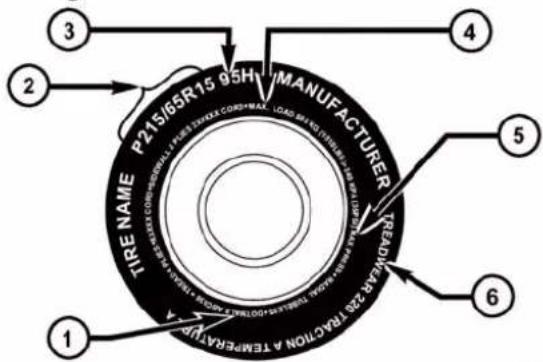
054903773
1 — U.S. DOT Safety Standards
4 — Maximum Load
Code (TIN)
5 — Maximum Pressure
2 — Size Designation
6 — Treadwear, Traction and
3 — Service Description
Temperature Grades
- P (Passenger) — Metric tire sizing is based on U.S. design standards. P-Metric tires have the letter "P" molded into the sidewall preceding the size designation. Example: P215/65R15 95H.
- European — Metric tire sizing is based on European design standards. Tires designed to this standard have the tire size molded into the sidewall beginning with the section width. The letter "P" is absent from this tire size designation. Example: 215/65R15 96H.
-
LT (Light Truck) — Metric tire sizing is based on U.S. design standards. The size designation for LT-Metric tires is the same as for P-Metric tires except for the letters "LT" that are molded into the sidewall preceding the size designation. Example: LT235/85R16.
-
Temporary spare tires are designed for temporary emergency use only. Temporary high pressure compact spare tires have the letter "T" or "S" molded into the sidewall preceding the size designation. Example: T145/80D18 103M.
- High flotation tire sizing is based on U.S. design standards and it begins with the tire diameter molded into the sidewall. Example: 31x10.5 R15 LT.
TireSizingChart
EXAMPLE:
| ExampleSizeDesignation:P215/65R15XL95H,215/65R1596H,LT235/85R16C,T145/80D18103M,31x10.5R15LT |
| P= Passenger car tire size based on U.S. design standards, or"....blank..." = Passenger car tire based on European design standards, orLT= Light truck tire based on U.S. design standards, orT o r S = Temporary spare tire or31= Overall diameter in inches (in) |
| 215,235,145= Section width in millimeters (mm) |
| 65,85,80= Aspect ratio in percent (%)– Ratio of section height to section width of tire, or10.5= Section width in inches (in) |
| R= Construction code– "R"means radial construction, or– "D"means diagonal or bias construction |
| 15,16,18= Rim diameter in inches (in) |
| 95= Load Index– A numerical code associated with the maximum load a tire can carry |
| H= Speed Symbol– A symbol indicating the range of speeds at which a tire can carry a load corresponding to its load index under certain operating conditions– The maximum speed corresponding to the speed symbol should only be achieved under specified operating conditions (i.e., tire pressure, vehicle loading, road conditions, and posted speed limits) |
LoadIdentification:
| Absence of the following load identification symbols on the sidewall of the tire indicates a Standard Load (SL) tire: |
| XL= Extra load (or reinforced) tire, or |
| LL= Light load tire or |
| C, D, E, F, G = Load range associated with the maximum load a tire can carry at a specified pressure |
MaximumLoad- Maximum load indicates the maximum load this tire is designed to carry
| MaximumPressure – Maximum pressure indicates the maximum permissible cold tire inflation pressure for this tire |
The TIN may be found on one or both sides of the tire, however, the date code may only be on one side. Tires with white sidewalls will have the full TIN, including the date code, located on the white sidewall side of the tire.
Look for the TIN on the outboard side of black sidewall tires as mounted on the vehicle. If the TIN is not found on the outboard side, then you will find it on the inboard side of the tire.
| EXAMPLE: |
| DOTMAL9ABCD0301 |
| DOT= Department of Transportation- This symbol certifies that the tire is in compliance with the U.S. Department of Transportation tire safety standards and is approved for highway use |
| MA= Code representing the tire manufacturing location (two digits) |
| L9= Code representing the tire size (two digits) |
| ABCD= Code used by the tire manufacturer (one to four digits) |
| 03= Number representing the week in which the tire was manufactured (two digits)- 03 means the 3rd week |
| EXAMPLE: |
| DOTMAL9ABCD0301 |
| 01= Number representing the year in which the tire was manufactured (two digits) - 01 means the year 2001 - Prior to July 2000, tire manufacturers were only required to have one number to represent the year in which the tire was manufactured. Example: 031 could represent the 3rd week of 1981 or 1991 |
TireTerminologyAndDefinitions
| TermDefinition | |
| B-PillarThe vehicle B-Pillar | is the structural member of the body located behind the front door. |
| ColdTireInflationPressureCold tire inflation pressure is defined as the tire pressure after the vehicle has not been driven for at least three hours, or driven less than 1 mile (1.6 km) after sitting for a minimum of three hours. Inflation pressure is measured in units of PSI (pounds per square inch) or kPa (kilopascals). | |
| TermDefinition | |
| MaximumInflationPressureThe maximum inflation pressure is the maximum permissible cold tire inflation pressure for this tire. The maximum inflation pressure is molded into the sidewall. | |
| RecommendedColdTireInflation Pressure | Vehicle manufacturer's recommended cold tire inflation pressure as shown on the tire placard. |
| TirePlacardA label permanently attached to the vehicle describing the vehicle's loading capacity, the original equipment tire sizes and the recommended cold tire inflation pressures. | |
NOTE: The proper cold tire inflation pressure is listed on the driver's side B-Pillar or the rear edge of the driver's side door.
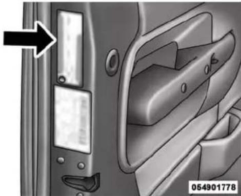
natural_image
Interior view of a car door with handle and door lock, showing no text or symbols on the door itselfExampleTirePlacardLocation(Door)
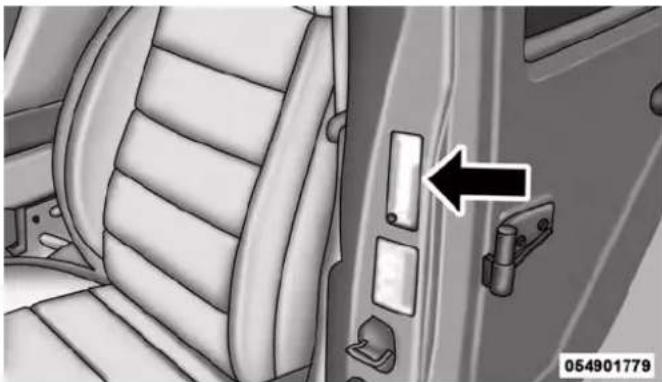
natural_image
Interior view of a car showing seat, door, and latch mechanism (no text or symbols)ExampleTirePlacardLocation(B-Pillar)
This placard tells you important information about the:
- Number of people that can be carried in the vehicle.
- Total weight your vehicle can carry.
-
Tire size designed for your vehicle.
-
Cold tire inflation pressures for the front, rear, and spare tires.
Loading
The vehicle maximum load on the tire must not exceed the load carrying capacity of the tire on your vehicle. You will not exceed the tire's load carrying capacity if you adhere to the loading conditions, tire size, and cold tire inflation pressures specified on the Tire and Loading Information placard and in the "Vehicle Loading" section of this manual.
NOTE: Under a maximum loaded vehicle condition, gross axle weight ratings (GAWRs) for the front and rear axles must not be exceeded. For further information on GAWRs, vehicle loading, and trailer towing, refer to "Vehicle Loading" in this section.
To determine the maximum loading conditions of your vehicle, locate the statement "The combined weight of
occupants and cargo should never exceed XXX lbs or XXX kg" on the Tire and Loading Information placard. The combined weight of occupants, cargo/luggage and trailer tongue weight (if applicable) should never exceed the weight referenced here.
StepsForDeterminingCorrectLoadLimit
- Locate the statement "The combined weight of occupants and cargo should never exceed XXX lbs or XXX kg" on your vehicle's placard.
- Determine the combined weight of the driver and passengers that will be riding in your vehicle.
- Subtract the combined weight of the driver and passengers from XXX lbs or XXX kg.
- The resulting figure equals the available amount of cargo and luggage load capacity. For example, if "XXX" amount equals 1,400 lbs (635 kg) and there will be five 150 lb (68 kg) passengers in your vehicle, the
amount of available cargo and luggage load capacity is 650 lbs (295 kg) (since 5 x 150 lbs (68 kg) = 750 lbs (340 kg), and 1400 lbs (635 kg) - 750 lbs (340 kg) = 650 lbs [295 kg]).
- Determine the combined weight of luggage and cargo being loaded on the vehicle. That weight may not safely exceed the available cargo and luggage load capacity calculated in step 4.
NOTE:
- If your vehicle will be towing a trailer, load from your trailer will be transferred to your vehicle. The following table shows examples on how to calculate total load, cargo/luggage, and towing capacities of your vehicle with varying seating configurations and number and size of occupants. This table is for illustration purposes only and may not be accurate for the seating and load carry capacity of your vehicle.
- For the following example, the combined weight of occupants and cargo should never exceed 865 lbs (392 kg).
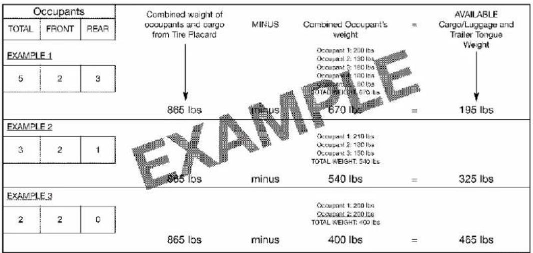
811add1t
Overloading of your tires is dangerous. Overloading can cause it re failure, affect vehicle handling, and increase your stopping distance. Usetires of the recommended load capacity for your vehicle. Never overload them.
TIRES—GENERALINFORMATION
TirePressure
Proper tire inflation pressure is essential to the safe and satisfactory operation of your vehicle. Four primary areas are affected by improper tire pressure:
- Safety and Vehicle Stability
• Economy
•Tread Wear - Ride Comfort
Safety
WARNING!
- Improperlyinflatedtiresaredangerousandcan causecollisions.
- Under-inflationincreasestireflexingandcanresultinoverheatingandtirefailure.
• Over-inflationreducesatire'sabilitytocushion shock.Objectsontheroadandchuckholescan causedamagethatresultintirefailure.
• Overinflatedorunder-inflatedtirescanaffective-vehiclehandlingandcanfailsuddenly, resulting in lossofvehiclecontrol. - Unequaltirepressurescancausesteeringproblems.Youcouldlosecontrolofyourvehicle.
(Continued)
WARNING!(Continued)
- Unequaltirepressuresfromonesideofthevehicle totheothercancausethevehicletodrifttothe rightorleft.
- Alwaysdrivewitheachtireinflatedtotherecommendedcoldtireinflationpressure.
Both under-inflation and over-inflation affect the stability of the vehicle and can produce a feeling of sluggish response or over responsiveness in the steering.
NOTE:
- Unequal tire pressures from side to side may cause erratic and unpredictable steering response.
- Unequal tire pressure from side to side may cause the vehicle to drift left or right.
Economy
Underinflated tires will increase tire rolling resistance resulting in higher fuel consumption.
TreadWear
Improper cold tire inflation pressures can cause abnormal wear patterns and reduced tread life, resulting in the need for earlier tire replacement.
RideComfortAndVehicleStability
Proper tire inflation contributes to a comfortable ride. Over-inflation produces a jarring and uncomfortable ride.
TireInflationPressures
The proper cold tire inflation pressure is listed on the driver's side B-Pillar or rear edge of the driver's side door.
At least once a month:
- Check and adjust tire pressure with a good quality pocket-type pressure gauge. Do not make a visual judgement when determining proper inflation. Tires may look properly inflated even when they are under-inflated.
- Inspect tires for signs of tire wear or visible damage.
CAUTION!
Afterinspectingoradjustingthetirepressure,alwaysreinstallthevalvestemcap.Thiswillprevent moistureanddirtfromenteringthevalvestem, whichcoulddamagethevalvestem.
Inflation pressures specified on the placard are always "cold tire inflation pressure." Cold tire inflation pressure is defined as the tire pressure after the vehicle has not been driven for at least three hours, or driven less than
1 mile (1.6 km) after sitting for a minimum of three hours. The cold tire inflation pressure must not exceed the maximum inflation pressure molded into the tire sidewall.
Check tire pressures more often if subject to a wide range of outdoor temperatures, as tire pressures vary with temperature changes.
Tire pressures change by approximately 1 psi (7 kPa) per 12^ F ( 7^ C) of air temperature change. Keep this in mind when checking tire pressure inside a garage, especially in the winter.
Example: If garage temperature = 68^ F ( 20^ C) and the outside temperature = 32^ F ( 0^ C) then the cold tire inflation pressure should be increased by 3 psi (21 kPa), which equals 1 psi (7 kPa) for every 12^ F ( 7^ C) for this outside temperature condition.
Tire pressure may increase from 2 to 6 psi (13 to 40 kPa) during operation. DO NOT reduce this normal pressure build up or your tire pressure will be too low.
TirePressuresForHighSpeedOperation
The manufacturer advocates driving at safe speeds and within posted speed limits. Where speed limits or conditions are such that the vehicle can be driven at high speeds, maintaining correct tire inflation pressure is very important. Increased tire pressure and reduced vehicle loading may be required for high-speed vehicle operation. Refer to your authorized tire dealer or original equipment vehicle dealer for recommended safe operating speeds, loading and cold tire inflation pressures.
WARNING!
Highspeeddrivingwithyourvehicleundermaxi- mumloadisdangerous.Theaddedstrainonyour tirescouldcausethemtofail.Youcouldhavea seriouscollision.Donotdriveavehicleloadedtothe maximumcapacityatcontinuousspeedsabove 75mph(120km/h).
RadialPlyTires
WARNING!
Combiningradialplytireswithothertypesoftires onyourvehiclewillcauseyourvehicletohandle poorly.Theinstabilitycouldcauseacollision.Alwaysuseradialplytiresinsetsoffour.Never combinethemwithothertypesoftires.
If your tire becomes damaged, it may be repaired if it meets the following criteria:
- The tire has not been driven on when flat.
- The damage is only on the tread section of your tire (sidewall damage is not repairable).
- The puncture is no greater than a 14 of an inch (6 mm).
Consult an authorized tire dealer for tire repairs and additional information.
Damaged Run Flat tires, or Run Flat tires that have experienced a loss of pressure should be replaced immediately with another Run Flat tire of identical size and service description (Load Index and Speed Symbol).
TireTypes
AllSeasonTires—IfEquipped
All Season tires provide traction for all seasons (spring, summer, fall and winter). Traction levels may vary between different all season tires. All season tires can be identified by the M+S, M&S, M/S or MS designation on the tire sidewall. Use all season tires only in sets of four; failure to do so may adversely affect the safety and handling of your vehicle.
SummerOrThreeSeasonTires—IfEquipped
Summer tires provide traction in both wet and dry conditions, and are not intended to be driven in snow or on ice. If your vehicle is equipped with summer tires, be aware these tires are not designed for winter or cold driving conditions. Install winter tires on your vehicle when ambient temperatures are less than 40^ F ( 5^ C) or if roads are covered with ice or snow. For more information, contact an authorized dealer.
Summer tires do not contain the all season designation or mountain/snowflake symbol on the tire sidewall. Use summer tires only in sets of four; failure to do so may adversely affect the safety and handling of your vehicle.
WARNING!
Donotusesummertiresinsnow/iceconditions. You could lose vehicle control, resulting in severe injury or death. Driving to fast for conditions also creates the possibility of loss of vehicle control.
SnowTires
Some areas of the country require the use of snow tires during the winter. Snow tires can be identified by a "mountain/snowflake" symbol on the tire sidewall.
If you need snow tires, select tires equivalent in size and type to the original equipment tires. Use snow tires only in sets of four; failure to do so may adversely affect the safety and handling of your vehicle.
Snow tires generally have lower speed ratings than what was originally equipped with your vehicle and should not be operated at sustained speeds over 75 mph (120 km/h). For speeds above 75 mph (120 km/h) refer to original equipment or an authorized tire dealer for recommended safe operating speeds, loading and cold tire inflation pressures.
While studded tires improve performance on ice, skid and traction capability on wet or dry surfaces may be poorer than that of non-studded tires. Some states prohibit studded tires; therefore, local laws should be checked before using these tire types.
RunFlatTires—IfEquipped
Run Flat tires allow you the capability to drive 50 miles (80 km) at 50 mph (80 km/h) after a rapid loss of inflation pressure. This rapid loss of inflation is referred to as the Run Flat mode. A Run Flat mode occurs when the tire inflation pressure is of/or below 14 psi (96 kPa). Once a Run Flat tire reaches the run flat mode it has limited driving capabilities and needs to be replaced immediately. A Run Flat tire is not repairable.
It is not recommended driving a vehicle loaded at full capacity or to tow a trailer while a tire is in the run flat mode.
See the tire pressure monitoring section for more information.
SpareTires—IfEquipped
NOTE: For vehicles equipped with Tire Service Kit instead of a spare tire, please refer to "Tire Service Kit" in "What To Do In Emergencies" for further information.
CAUTION!
Because of the reduced ground clearance, donottake your vehicle through an automatic car wash with a compactor limited - usetemporary spare installed. Damageto the vehicle may result.
SpareTireMatchingOriginalEquippedTireAndWheel—IfEquipped
Your vehicle may be equipped with a spare tire and wheel equivalent in look and function to the original
equipment tire and wheel found on the front or rear axle of your vehicle. This spare tire may be used in the tire rotation for your vehicle. If your vehicle has this option, refer to an authorized tire dealer for the recommended tire rotation pattern.
CompactSpareTire—IfEquipped
The compact spare is for temporary emergency use only. You can identify if your vehicle is equipped with a compact spare by looking at the spare tire description on the Tire and Loading Information Placard located on the driver's side door opening or on the sidewall of the tire. Compact spare tire descriptions begin with the letter "T" or "S" preceding the size designation. Example: T145/80D18 103M.
T, S = Temporary Spare Tire
Since this tire has limited tread life, the original equipment tire should be repaired (or replaced) and reinstalled on your vehicle at the first opportunity.
Do not install a wheel cover or attempt to mount a conventional tire on the compact spare wheel, since the wheel is designed specifically for the compact spare tire. Do not install more than one compact spare tire and wheel on the vehicle at any given time.
WARNING!
Compactsparesarefortemporaryemergencyuse only.Withthesespares,donotdrivemorethan 50mph(80km/h).Temporaryusespareshavelimited treadlife.Whenthetreadisworntothetreadwear indicators,thetemporaryusesparetireneedstobe replaced.Besuretofollowthewarnings,which applytoyourspare.Failureretodosocouldresultin sparetirefailureandlossofvehiclecontrol.
FullSizeSpare—IfEquipped
The full size spare is for temporary emergency use only. This tire may look like the originally equipped tire on the front or rear axle of your vehicle, but it is not. This spare tire may have limited tread life. When the tread is worn to the tread wear indicators, the temporary use full size spare tire needs to be replaced. Since it is not the same as your original equipment tire, replace (or repair) the original equipment tire and reinstall on the vehicle at the first opportunity.
Limited-UseSpare—IfEquipped
The limited-use spare tire is for temporary emergency use only. This tire is identified by a label located on the limited-use spare wheel. This label contains the driving limitations for this spare. This tire may look like the original equipped tire on the front or rear axle of your vehicle, but it is not. Installation of this limited-use spare tire affects vehicle handling. Since it is not the same as
your original equipment tire, replace (or repair) the original equipment tire and reinstall on the vehicle at the first opportunity.
WARNING!
Limited-usesparesareforemergencyuseonly.Installationofthislimited-usesparetireaffectsvehicle handling.Withthistire,donotdrivemorethanthe speedlistedonthelimit-usesparewheel.Keep inflatedtothecoldtireinflationpressureslistedon yourTireandLoadingInformationPlacardlocated onthedriver'ssideB-Pillarortherearedgeofthe driver'ssidedoor.Replace(orrepair)theoriginal equipmenttireatthefirstopportunityandreinstallit onyourvehicle.Failureretodosocouldresultinloss ofvehiclecontrol.
TireSpinning
When stuck in mud, sand, snow, or ice conditions, do not spin your vehicle's wheels above 30 mph (48 km/h) or for longer than 30 seconds continuously without stopping.
Refer to "Freeing A Stuck Vehicle" in "What To Do In Emergencies" for further information.
WARNING!
Fastspinningtirescanbedangerous. Forces generated by excessive wheels speeds may cause tired damage or failure. Atire could explode and injuresome one. Donot spiny our vehicle's wheels faster than 30 mph (48 km/h) form more than 30 seconds continuously when you are stuck, and donot let any on near aspinning wheel, nomatter what the speed.
TreadWearIndicators
Tread wear indicators are in the original equipment tires to help you in determining when your tires should be replaced.
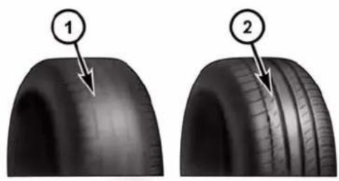
natural_image
Two views of a car tire showing tread pattern and tire structure (no text or symbols)055007576
1 — Worn Tire
2—New Tire
These indicators are molded into the bottom of the tread grooves. They will appear as bands when the tread depth becomes a 1/16 of an inch (2 mm). When the tread is worn to the tread wear indicators, the tire should be replaced. Refer to “Replacement Tires” in this section for further information.
LifeOfTire
The service life of a tire is dependent upon varying factors including, but not limited to:
- Driving style.
- Tire pressure - Improper cold tire inflation pressures can cause uneven wear patterns to develop across the tire tread. These abnormal wear patterns will reduce tread life, resulting in the need for earlier tire replacement.
- Distance driven.
- Performance tires, tires with a speed rating of V or higher, and summer tires typically have a reduced tread life. Rotation of these tires per the vehicle maintenance schedule is highly recommended.
WARNING!
Tiresandthesparetireshouldbereplacedaftersix years,regardlessoftheremainingtread.Failureto followthiswarningcanresultinsuddentirefailure. Youcouldlosecontrolandhaveacollisionresulting inseriousinjuryordeath.
Keep dismounted tires in a cool, dry place with as little exposure to light as possible. Protect tires from contact with oil, grease, and gasoline.
ReplacementTires
The tires on your new vehicle provide a balance of many characteristics. They should be inspected regularly for
wear and correct cold tire inflation pressures. The manufacturer strongly recommends that you use tires equivalent to the originals in size, quality and performance when replacement is needed. Refer to the paragraph on "Tread Wear Indicator." Refer to the Tire and Loading Information placard or the Vehicle Certification Label for the size designation of your tire. The Load Index and Speed Symbol for your tire will be found on the original equipment tire sidewall. See the Tire Sizing Chart example found in the Tire Safety Information section of this manual for more information relating to the Load Index and Speed Symbol of a tire.
It is recommended to replace the two front tires or two rear tires as a pair. Replacing just one tire can seriously affect your vehicle's handling. If you ever replace a wheel, make sure that the wheel's specifications match those of the original wheels.
It is recommended you contact your authorized tire dealer or original equipment dealer with any questions
you may have on tire specifications or capability. Failure to use equivalent replacement tires may adversely affect the safety, handling, and ride of your vehicle.
WARNING!
- Donotuseatire, wheelsizeorratingotherthan thatspecifiedforyourvehicle. Some combinations of unapprovedtiresandwheelsmaychangesuspensiondimensionsandperformancecharacteristics, resultinginchangestosteering, handling, and brakingofyourvehicle. This can cause unpredictablehandlingandstresstosteeringandsuspensioncomponents. You could lose control and have a collision resulting in serious injury or death. Use only the tire and wheelsizes with load ratings approved for your vehicle.
(Continued)
WARNING!(Continued)
- Neveruseatirewithasmallerloadindexor capacity,otherthanwhatwasoriginallyequipped onyourvehicle.Usingatirewithasmallerload indexcouldresultintireoverloadingandfailure. Youcouldlosecontrolandhaveacollision.
- Failuretoequipyourvehiclewithtireshaving adequatespeedcapabilitycanresultinsuddentire failureandlossofvehiclecontrol.
CAUTION!
Replacingoriginaltireswithtiresofadifferentensize mayresultinfalsespeedometerandodometerreadings.
TIRECHAINS(TRACTIONDEVICES)
Use of traction devices require sufficient tire-to-body clearance. Follow these recommendations to guard against damage.
- Traction device must be of proper size for the tire, as recommended by the traction device manufacturer.
• Install on Rear Tires Only. - Reduced size snow chains with a maximum projection of 7 mm beyond the tire profile can be fitted on cars equipped with 235/40 R18 rear tire.
CAUTION!
To avoid damagetoyourvehicleortires, observethe following precautions:
- Because of restricted traction device clearance between it is also a basis of the importance of the important that only traction devices are good condition are used. Brokendevices can cause serious damage. Stop the vehicle immediately if noise occurs that could indicate device breakage. Remove the damaged part of the device before further use.
- Installdeviceastightlyaspossibleandthenretightenafterdrivingabout ^1/2 mile(0.8km).
- Donotexceed30mph(48km/h).
- Drivecautiously and avoid severeturns and large bumps, especially with loaded vehicle.
- Donotdriveforaprolongedperiodondrypavement.
CAUTION!(Continued)
- Observethetractiondevicemanufacturer's instructionsonthemethodofinstallation,operating speed,andconditionsforuse.Alwaysusethe suggestedoperatingspeedofthedevicemanufac-turer'sifitislessthan30mph(48km/h).
- Donotusetractiondevicesonacompactsparetire.
Due to tire design and size, tire rotations on this vehicle are not possible.
NOTE: For AR 4C models, where available, the vehicle may be equipped with high performance tires that guarantee high grip performance with little increase of wear. Alfa Romeo, in collaboration with Pirelli, developed a specific high performance tire for the 4C model. A dedicated Pirelli PZero, identified with an AR mark, guarantees this vehicle to obtain the highest performance capable.
TIREPRESSUREMONITORINGSYSTEM(TPMS)
The Tire Pressure Monitor System (TPMS) will warn the driver of a low tire pressure based on the vehicle recommended cold tire pressure.
The tire pressure will vary with temperature by about 1 psi (7 kPa) for every 12^ F ( 6.5^ C). This means that when the outside temperature decreases, the tire pressure will decrease. Tire pressure should always be set based on cold inflation tire pressure. This is defined as the tire pressure after the vehicle has not been driven for at least three hours, or driven less than 1 mile (1.6 km) after a three hour period. The cold tire inflation pressure must not exceed the maximum inflation pressure molded into the tire sidewall. Refer to “Tires – General Information” in “Starting and Operating” for information on how to properly inflate the vehicle’s tires. The tire pressure will also increase as the vehicle is driven, this is normal and there should be no adjustment for this increased pressure.
The TPMS will warn the driver of a low tire pressure if the tire pressure falls below the low pressure warning limit for any reason, including low temperature effects, or natural pressure loss through the tire.
The TPMS will continue to warn the driver of low tire pressure as long as the condition exists, and will not turn off until the tire pressure is at or above the recommended cold tire pressure on the placard. Once the low tire pressure warning (Tire Pressure Monitoring Telltale
Light) illuminates, you must increase the tire pressure to the recommended cold tire pressure in order for the Tire Pressure Monitoring Telltale Light to turn off. The system will automatically update and the Tire Pressure Monitoring Telltale Light will turn off once the system receives the updated tire pressures. The vehicle may need to be driven for up to 20 minutes above 15 mph (24 km/h) in order for the TPMS to receive this information.
For example, your vehicle may have a recommended cold (parked for more than three hours) tire pressure of 30 psi (207 kPa). If the ambient temperature is 68^ F ( 20^ C) and the measured tire pressure is 27 psi (186 kPa), a temperature drop to 20^ F ( -7^ C) will decrease the tire pressure to approximately 23 psi (159 kPa). This tire pressure is sufficiently low enough to turn on the Tire Pressure Monitoring Telltale Light. Driving the vehicle may cause the tire pressure to rise to approximately 27 psi (186 kPa), but the Tire Pressure Monitoring Telltale Light will still be on. In this situation, the Tire Pressure Monitoring Telltale Light will turn off only after the tires are inflated to the vehicle's recommended cold tire pressure value.
CAUTION!
- TheTPMShasbeenoptimizedfortheoriginal equipmenttiresandwheels.TPMSpressuresand warningshavebeenestablishedforthetiresize equippedonyourvehicle.Undesirablesystemoperationorsensordamagemayresultwhenusing replacementequipmentthatisnotofthesamesize, type,and/orstyle.Aftermarketwheelscancause sensordamage.Usingaftermarkettiresealantsmay causetheTirePressureMonitoringSystem(TPMS) sensorobecomeinoperable.Afterusinganaftermarkettiresealantitisrecommendedthatyoutake
(Continued)
CAUTION!(Continued)
yourvehicletoyouranauthorizeddealershipto haveyoursensorfunctionchecked.
- Afterinspectingoradjustingthe tirepressure, alwaysreinstallthevalvestemcap.Thiswill preventmoistureanddirtfromenteringthevalve stem,whichcoulddamagetheTirePressureMonitoringSensor.
NOTE:
- The TPMS is not intended to replace normal tire care and maintenance, or to provide warning of a tire failure or condition.
- The TPMS should not be used as a tire pressure gauge while adjusting your tire pressure.
- Driving on a significantly under-inflated tire causes the tire to overheat and can lead to tire failure.
Under-inflation also reduces fuel efficiency and tire tread life, and may affect the vehicle's handling and stopping ability.
- The TPMS is not a substitute for proper tire maintenance, and it is the driver's responsibility to maintain correct tire pressure using an accurate tire gauge, even if under-inflation has not reached the level to trigger illumination of the Tire Pressure Monitoring Telltale Light.
- Seasonal temperature changes will affect tire pressure, and the TPMS will monitor the actual tire pressure in the tire.
BaseSystem

This is the TPMS warning indicator located in the instrument cluster.
The TPMS uses wireless technology with wheel rim mounted electronic sensors to monitor tire pressure levels. Sensors, mounted to each wheel as part of the valve stem, transmit tire pressure readings to the Receiver Module.
NOTE: It is particularly important for you to check the tire pressure in all of the tires on your vehicle regularly and to maintain the proper pressure.
The TPMS consists of the following components:
- Receiver Module.
- Four Tire Pressure Monitoring Sensors.
•Tire Pressure Monitoring Telltale Light.
TirePressureMonitoringLowPressureWarnings
The Tire Pressure Monitoring Telltale Light will illuminate in the instrument cluster, an audible chime will be activated, and the “Check left or right front/rear tire”
text message will display when one or more of the four active road tire pressures are low. Should this occur, you should stop as soon as possible, check the inflation pressure of each tire on your vehicle, and inflate each tire to the vehicle's recommended cold placard pressure value. The system will automatically update and the Tire Pressure Monitoring Light will extinguish once the updated tire pressures have been received. The vehicle may need to be driven for up to 20 minutes above 15 mph (24 km/h) to receive this information.
CheckTPMSWarnings
The Tire Pressure Monitoring Telltale Light will flash on and off for 75 seconds and remain on solid when a system fault is detected, the "TIRE PRESSURE MONITORING UNAVAILABLE" text message will display. If the ignition key is cycled, this sequence will repeat providing the system fault still exists. The Tire Pressure Monitoring
Telltale Light will turn off when the fault condition no longer exists. A system fault can occur with any of the following scenarios:
- Jamming due to electronic devices or driving next to facilities emitting the same radio frequencies as the TPM sensors.
- Installing some form of aftermarket window tinting that affects radio wave signals.
- Snow or ice around the wheels or wheel housings.
- Using tire chains on the vehicle.
- Using wheels/tires not equipped with TPM sensors.
NOTE: Your vehicle may be equipped with a compact spare wheel and tire assembly.
-
The compact spare tire does not have a tire pressure monitoring sensor. Therefore, the TPMS will not monitor the tire pressure in the compact spare tire.
-
If you install the compact spare tire in place of a road tire that has a pressure below the low-pressure warning limit, upon the next ignition key cycle, a chime will sound and the Tire Pressure Monitoring Telltale Light will still turn ON due to the low tire.
- However, after driving the vehicle for up to 20 minutes above 15 mph (24 km/h), the Tire Pressure Monitoring Telltale Light will flash on and off for 75 seconds and then remain on solid.
- This occurs for each subsequent ignition key cycle, a chime will sound and the Tire Pressure Monitoring Telltale Light will flash on and off for 75 seconds and then remain on solid.
- Once you repair or replace the original road tire and reinstall it on the vehicle in place of the compact spare tire, the TPMS will update automatically and the Tire Pressure Monitoring Telltale Light will turn OFF, as long as no tire pressure is below the low-pressure
warning limit in any of the four active road tires. The vehicle may need to be driven for up to 20 minutes above 15 mph (24 km/h) in order for the TPMS to receive this information.
GeneralInformation
This device complies with Part 15 of the FCC rules and RSS 210 of Industry Canada. Operation is subject to the following conditions:
- This device may not cause harmful interference.
- This device must accept any interference received, including interference that may cause undesired operation.
The tire pressure sensors are covered under one of the following licenses:
United States MRXC4W4MA4
Canada 2546A-C4W4MA4 (Single)
FUELREQUIREMENTS—1.750Turbo
The 1.750 turbo engine is designed to meet all emissions regulations and provide excellent fuel economy and performance when using high-quality premium unleaded gasoline with an octane rating of
Only91orhigher.
Light spark knock at low engine speeds is not harmful to your engine. However, continued heavy spark knock at high speeds can cause damage and immediate service is required.
Poor quality gasoline can cause problems such as hard starting, stalling and hesitations. If you experience these symptoms, try another brand of gasoline (with the appropriate octane rating for your engine) before considering service for the vehicle.
Reformulated Gasoline
Many areas of the country require the use of cleaner burning gasoline referred to as “Reformulated Gasoline.” Reformulated gasoline contain oxygenates and are specifically blended to reduce vehicle emissions and improve air quality.
The manufacturer supports the use of reformulated gasoline. Properly blended reformulated gasoline will provide excellent performance and durability of engine and fuel system components.
Gasoline/OxygenateBlends
Some fuel suppliers blend unleaded gasoline with oxygenates such as 10% Ethanol, Methyl Tert-Butyl Ether (MTBE), and Ethyl Tret-Butyl Ether (ETBE). Oxygenates are required in some areas of the country during the winter months to reduce carbon monoxide emissions.
Fuels blended with these oxygenates may be used in your vehicle.
CAUTION!
Donotuse gasoline containing Methanol or E-85 Ethanol. Use of these blends may result in starting and drivability problems and may damage critical fuel system components.
Problems that result from using methanol/gasoline blends are not the responsibility of the manufacturer. While MTBE is an oxygenate made from Methanol, it does not have the negative effects of Methanol.
MMTInGasoline
Methylcyclopentadienyl Manganese Tricarbonyl (MMT) is a manganese-containing metallic additive that is blended into some gasoline to increase octane. Gasoline blended with MMT provides no performance advantage
beyond gasoline of the same octane number without MMT. Gasoline blended with MMT reduces spark plug life and reduces emissions system performance in some vehicles. The manufacturer recommends that gasoline without MMT be used in your vehicle. The MMT content of gasoline may not be indicated on the gasoline pump, therefore, you should ask your gasoline retailer whether the gasoline contains MMT. MMT is prohibited in Federal and California reformulated gasoline.
MaterialsAddedToFuel
All gasoline sold in the United States is required to contain effective detergent additives. Use of additional detergents or other additives is not needed under normal conditions and they would result in additional cost. Therefore, you should not have to add anything to the fuel.
FuelSystemCautions
CAUTION!
Followtheseguidelinesomaintainyourvehicle's performance:
- The useofleadedgasisprohibitedbyFederallaw. Using leadedgasolinecanimpairengineperformanceanddamagetheemissionscontrolsystem.
- Anout-of-tuneengineorcertainfuelorignition malfunctionscancausethecatalyticconverterto overheat. If you notice apungentburningodor or somelightsmoke, you'renginemaybeoutoftune ormalfunctioning and may require immediateservice. Contact your authorized dealer for service assistance.
(Continued)
CAUTION!(Continued)
- Theuseoffueladditives, which are now being sold as octaneenhancers, is not recommended. Most of these products contain high concentrations of methanol. Fuelsystem damage or vehicle performance problems resulting from the use of such fuel soradditives is not the responsibility of the manufacturer.
NOTE: Intentional tampering with the emissions control system can result in civil penalties being assessed against you.
CarbonMonoxideWarnings
WARNING!
Carbonmonoxide(CO)inexhaustgasesisdeadly. Followtheprecautionsbelowtopreventcarbon monoxidepoisoning:
- Donotinhaleexhaustgases. They contain carbon monoxide, acolorless and odorless gas, which can kill. Never run the engine in a closed area, such as agarage, and never sit in a parked vehicle with the engineer running for an extended period. If the vehicle is stopped in an open area with the engine running for more than a short period, adjust the ventilation system to force fresh, outside air into the vehicle.
- Guardagainstcarbonmonoxidewithpropermaintenance.Havetheexhaustsysteminspectedevery
(Continued)
timethevehicleisraised.Haveanyabnormal conditionsrepairedpromptly.Untilrepaired,drive withallsidewindowsfullyopen.
ADDINGFUEL/SMARTFUEL
NOTE:
- The "Smart Fuel" is a device placed on the top of the filler pipe, it opens and closes automatically when the fuel nozzle is inserted or extracted.
- Only the correct nozzle size diameter allows the flap door to open when the nozzle is inserted.
RefuelingProcedure
- Open the fuel filler door pulling towards outside.
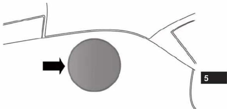
natural_image
Diagram showing a curved path with a shaded circle and an arrow pointing to it, labeled '5' (no text or symbols beyond the number)FuelFillerDoorLocation
- There is no fuel filler cap. A flap door inside the pipe seals the system.
natural_image
Technical line drawing of a mechanical component with internal cavities and mounting bracket (no text or symbols)FuelNozzleLocation
-
Insert the fuel nozzle into the filler pipe (the nozzle opens and holds the flap door while refueling) and start refueling – when the fuel nozzle "clicks" or shuts off, the fuel tank is full.
-
At the end of refueling, before removing the nozzle, wait at least 10 seconds to allow the fuel to flow within the tank.
- Remove the fuel nozzle from the filler pipe and then close the fuel door.
EmergencyGasCanRefueling:
Most gas cans will not open the flapper door.
A funnel is provided to open the flapper door to allow emergency refueling with a gas can.
- Retrieve the appropriate funnel from the storage area in the luggage compartment.
- Insert funnel into same filler pipe opening as the fuel nozzle.
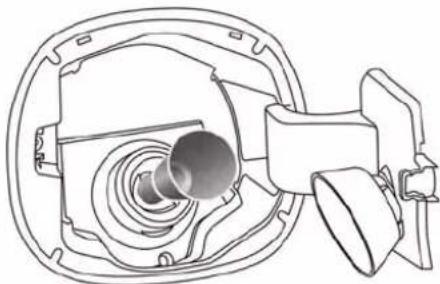
natural_image
Technical line drawing of a mechanical component with concentric circular features and a central shaft (no text or symbols)EmergencyFuelFillLocation
- Ensure funnel is inserted fully to hold flapper door open.
- Pour fuel into funnel opening.
- Remove funnel from filler pipe, clean off prior to putting back in the storage area.
CAUTION!
Toavoidfuelspillageandoverfilling, donot "top off" thefueltankafterfilling.
WARNING!
- Neverhaveanysmokingmaterialslitinornearthe vehiclewhenthefueldoorisopenorthetankis beingfilled.
- Neveraddfuelwhentheengineisrunning. This is inviolationofmoststateandfederalfireregulationsandmaycausethe"MalfunctionIndicator Light"toturnon.
- Afiremayresultiffuelispumpedintoaportable containerthatisinsideofavehicle.Youcouldbe burned.Alwaysplacefuelcontainersonthe groundwhilefilling.
TRAILERTOWING
Trailer towing with this vehicle is not recommended.
RECREATIONAL TOWING(BEHIND MOTORHOME, ETC.)
TowingThisVehicleBehindAnotherVehicle
NOTE: This vehicle may be towed on a flatbed or vehicle trailer provided all four wheels are OFFthe ground.
| CAUTION! |
| • DONOTflattowthisvehicle.Damagetothe drivetrainwillresult.• Donotdollytowthisvehicle.Useofatowingdolly cancausesignificantdamagetoyourvehicle.Damagefromimpropertowingisnotcoveredunderthe NewVehicleLimitedWarranty.• Towingthisvehicleinviolationoftheabovere-quirementscancauseseveretransmissiondamage. DamagefromimpropertowingisnotcoveredundertheNewVehicleLimitedWarranty. |
| TowingConditionWheelsOFF | theGroundAlfaTwinClutchTransmission | |
| Flat Tow None | NOTALLOWED | |
| Dolly Tow | Front | NOTALLOWED |
| Rear | NOTALLOWED | |
| On Trailer | All | OK |
WHATODOINEMERGENCIES
CONTENTS
■HAZARD WARNING FLASHER....220
■IF YOUR ENGINE OVERHEATS .....220
■WHEEL AND TIRE TORQUE SPECIFICATIONS .....221
□Torque Specifications....222
■TIRE SERVICE KIT....224
■JUMP-STARTING....228
□Preparations For Jump-Start .....228
□Jump-Starting Procedure....230
■FREEING A STUCK VEHICLE .....232
■ENHANCED ACCIDENT RESPONSE SYSTEM....234
■FRONT TOW EYE USAGE....236
■FIRE EXTINGUISHER — IF EQUIPPED .....239
220WHATODOINEMERGENCIES
The Hazard Warning flasher switch is located on the center console.

Press the switch to turn on the Hazard Warning flasher. When the switch is activated, all direc-
tional turn signals will flash on and off to warn oncoming traffic of an emergency. Press the switch a second time to turn off the Hazard Warning flasher.
This is an emergency warning system and it should not be used when the vehicle is in motion. Use it when your vehicle is disabled and it is creating a safety hazard for other motorists.
When you must leave the vehicle to seek assistance, the Hazard Warning flasher will continue to operate even though the ignition is placed in the OFF position.
NOTE: With extended use the Hazard Warning flasher may wear down your battery.
IFYOURENGINEOVERHEATS
In any of the following situations, you can reduce the potential for overheating by taking the appropriate action.
- On the highways — slow down.
- In city traffic — while stopped, place the transmission in NEUTRAL, but do not increase engine idle speed.
NOTE: There are steps that you can take to slow down an impending overheat condition:
- If your air conditioner (A/C) is on, turn it off. The A/C system adds heat to the engine cooling system and turning the A/C off can help remove this heat.
- You can also turn the temperature control to maximum heat, the mode control to floor and the blower control to high. This allows the heater core to act as a
supplement to the radiator and aids in removing heat from the engine cooling system.
CAUTION!
Drivingwithahotcoolingsystemcoulddamage yourvehicle.Ifthetemperaturegaugereads240°F (116°C)orgreaterpulloverandstopthevehicle.Idle thevehiclewiththeairconditionerturnedoffuntil thecoolanttemperaturedropsbackintothenormal range200–230°F(93–110°C).Thedigitalwarninglight mayswitchon(togetherwithamessageonthe display)toindicatethatthecoolanttemperatureis toohigh;inthiscase,stoptheengineandcallfor service.
WARNING!
Youorotherscanbebadlyburnedbyhotengine coolant(antifreeze)orsteamfromyourradiator.If youseeorhearsteamcomingfromunderthehood, donotopenthehooduntiltheradiatorhashadtime tocool.Nevertrytoopenacoolingsystempressure capwhentheradiatororcoolantbottleishot.
WHEELANDTIRETORQUESPECIFICATIONS
Proper lug nut/bolt torque is very important to ensure that the wheel is properly mounted to the vehicle. Any time a wheel has been removed and reinstalled on the vehicle the lug nuts/bolts should be torqued using a properly calibrated torque wrench.
222WHATODOINEMERGENCIES
TorqueSpecifications
| LugNut/BoltTorque** | LugNut/ BoltSize | LugNut/Bolt SocketSize |
| 72 Ft-Lbs (98 N·m) M1 | 2 x 1.25 17 mm |
**Use only Alfa Romeo recommended lug nuts/bolts and clean or remove any dirt or oil before tightening.
Inspect the wheel mounting surface prior to mounting the tire and remove any corrosion or loose particles.
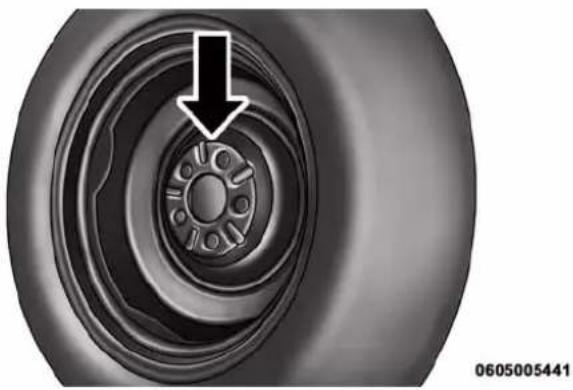
natural_image
Close-up of a car tire with a circular head and central hub, showing mechanical components (no text or symbols)WheelMountingSurface
Tighten the lug nuts/bolts in a star pattern until each nut/bolt has been tightened twice.
WHATODOINEMERGENCIES223
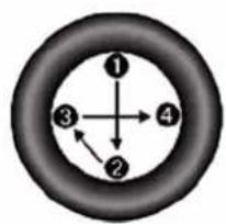
flowchart
graph TD
    A["1"] --> B["2"]
    B --> C["3"]
    C --> D["4"]
    D --> A
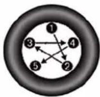
flowchart
graph TD
    1 --> 2
    2 --> 3
    3 --> 4
    4 --> 1
    5 --> 2
    5 --> 3
    5 --> 4
    1 --> 3
    2 --> 4
    3 --> 4
    4 --> 1
0605006372
After 25 miles (40 km) check the lug nut/bolt torque to be sure that all the lug nuts/bolts are properly seated against the wheel.
WARNING!
Toavoidtheriskoffforcingthevehicleoffthejack, donottightenthelugnutsfullyuntilthevehiclehas beenlowered.Failureretofollowthiswarningmay resultinpersonalinjury.
TorquePatterns
224WHATODOINEMERGENCIES
TIRESERVICEKIT
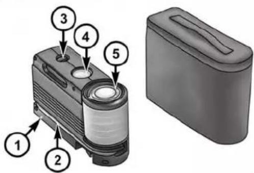
0604040379
TireServiceKitComponents
1 — Power Plug (located on bottom side of Tire Service Kit)
2 — Sealant Hose (Clear)
3 — Power Button
4 — Pressure Gauge
5 — Sealant Bottle
If a tire is punctured, you can make a first emergency repair using the Tire Service Kit located in the rear storage area under the decklid.
Tire punctures of up to 1/4" (6 mm) can be repaired; the kit can be used in all weather conditions. Do not remove the foreign object from the punctured tire, i.e., screw or nail.
Remove the Tire Service Kit from the vehicle, take it out from the bag and place it near the punctured tire. Screw the clear flexible filling tube to the tire valve.
WARNING!
- Donotattempttosealatireonthesideofthe vehicleclosesttotraffic.Pullfarenoughoffthe roadtoavoidthedangerofbeinghitwhenusing theTireServiceKit.
(Continued)
WARNING!(Continued)
- DonotuseTireServiceKitordrivethevehicle underthefollowingcircumstances:
-Ifthepunctureinthetiretreadisapproximately 1/4"(6mm)orlarger.
-Ifthetirehasanysidewalldamage.
-If the tire has any damage from driving with extremely low tire pressure.
-If the tire has any damage from driving on a flat tire.
-Ifthewheelhasanydamage.
-If you are unsure of the condition of the tire or the wheel. - KeepTireServiceKitawayfromopenflamesor heatsource.
- AlooseTireServiceKitthrownforwardina collisionorhardstopcouldendangertheoccupants
WARNING!(Continued)
ofthevehicle.AlwaysstowtheTireServiceKitin theplaceprovided.Failureretofollowthesewarningscanresultininjuriesthatareseriousorfatalto you,yourpassengers,andothersaroundyou.
• TakecarenottoallowthecontentsofTireService Kittocomeincontactwithhair,eyes,orclothing. TireServiceKitsealantisharmfulifinhaled, swallowed,orabsorbedthroughtheskin.Itcauses skin,eye,andrespiratoryirritation.Flushimmediatelywithplentyofwaterifthereisanycontact witheysorskin.Changeclothingassoonas possible,ifthereisanycontactwithclothing.
- TireServiceKitSealantsolutioncontainslatex.In caseofanallergicreactionorrash,consultaphysicianimmediately.KeepTireServiceKitoutof
(Continued)
(Continued)
WARNING!(Continued)
reachofchildren.Ifswallowed,rinsemouthimmediatelywithplentyofwateranddrinkplentyof water.Donotinducevomiting!Consultaphysician immediately.
Insert the power plug into the vehicle power outlet socket. Start the vehicle engine.
Press the Tire Service Kit power button to the "I" position. The electric compressor will be turned on, sealant and air will inflate the tire.
Minimum 26 psi (1.8 bar) of pressure should be reached within 20 minutes. If the pressure has not been reached turn off and remove the Tire Service Kit, drive the vehicle 30 feet (10 meters) back and forth, to better distribute the sealant inside the tire.
Attach the clear flexible filling tube of the compressor directly to the tire valve and repeat the inflation process.
When the correct pressure has been reached, start driving the vehicle to uniformly distribute the sealant inside the tire. After 10 minutes, stop and check the tire pressure. If the pressure is below 19 psi (1.3 bar), do not drive the vehicle, as the tire is too damaged, contact the nearest Authorized Dealer.
WARNING!
TireServiceKitisnotapermanentflattirerepair. Havethetireinspectedandrepairedorreplacedafter using Tire Service Kit. Do not exceed 65 mph (110km/h)untilthetireisrepairedorreplaced. Failuretofollowthiswarningcanresultininjuries thatareseriousorfataltoyou,yourpassengers,and othersaroundyou.Havethetirecheckedassoonas possibleatanAuthorizedDealer.
If the pressure is at 19 psi (1.3 bar) or above repeat the inflation process to reach the correct tire pressure and continue driving.
Peel off the warning label from the bottle and place it on the dashboard as a reminder to the driver that the tire has been treated with Tire Service Kit.
WARNING!
ThemetalendfittingfromPowerPlugmaygethot afteruse,soitshouldbehandledcarefully.
NOTE:Replace the sealant canister prior to the expiration date at your Authorized Dealer.
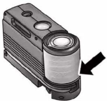
natural_image
3D rendering of a cylindrical mechanical component with a black arrow pointing to it (no text or symbols visible)0604040380
TireServiceKitExpirationDateLocation
WARNING!
Storethesealantcanisterinitsspecialcompartment, awayfromsourcesofheat.
228WHATODOINEMERGENCIES
JUMP-STARTING
If your vehicle has a discharged battery it can be jump-started using a set of jumper cables and a battery in another vehicle or by using a portable battery booster pack. Jump-starting can be dangerous if done improperly so please follow the procedures in this section carefully.
NOTE: When using a portable battery booster pack follow the manufacturer's operating instructions and precautions.
CAUTION!
Donotuseaportablebatteryboosterpackorany otherboostersourcewithasystemvoltagegreater than12Voltsordamagetothebattery,startermotor, alternatororelectricalsystemmayoccur.
WARNING!
Donotattemptjump-startingifthebatteryisfrozen. Itcouldruptureorexplodeandcausepersonalinjury.
PreparationsForJump-Start
The battery in your vehicle is located on the left side of the engine compartment. To access the battery remove the protective cover.
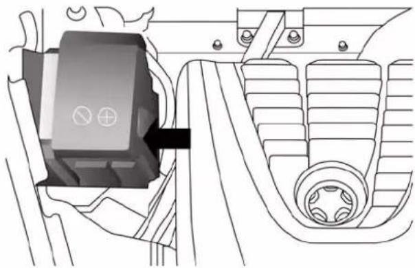
natural_image
Technical line drawing of a mechanical component with no visible text or symbolsBatteryLocation
WARNING!
- Removeanymetaljewelrysuchasrings, watch bandsandbraceletsthatcouldmakeaninadvertent electricalcontact. Youcouldbeseriouslyinjured.
WARNING!(Continued)
- Batteriescontainsulfuricacidthatcanburnyour skinoreyesandgeneratehydrogengaswhichis flammableandexplosive.Keepopenflamesor sparksawayfromthebattery.
NOTE: Be sure that the disconnected ends of the cables do not touch while still connected to the other vehicle.
-
Firmly apply the parking brake, and turn the ignition OFF.
-
Turn off the heater, radio, and all unnecessary electrical accessories.
-
To remove the protective cover off the battery, pull upward on the cover.
(Continued)
230WHATODOINEMERGENCIES
- If using another vehicle to jump-start the battery, park the vehicle within the jumper cables reach, set the parking brake and make sure the ignition is OFF.
WARNING!
Donotallowvehiclestotoucheachotherasthis couldestablishagroundconnectionandpersonal injurycouldresult.
Jump-StartingProcedure
WARNING!
Failure to follow this jump-starting procedure could result in personal injury or property damaged due to battery explosion.
CAUTION!
Failure to follow these procedures could result in damageto the charging system of the booster vehicle orthedischarged vehicle.
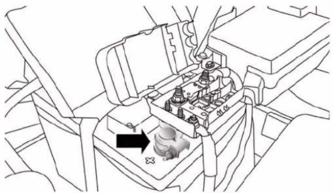
natural_image
Line drawing of a car engine compartment with internal components and a black arrow indicating a component (no text or symbols present)Positive(+)BatteryPost
ConnectingTheJumperCables
- Connect the positive (+) end of the jumper cable to the positive (+) post of the vehicle with the discharged battery.
- Connect the opposite end of the positive (+)jumper cable to the positive (+)post of the booster battery.
- Connect the negative end (-) of the jumper cable to the negative (-) post of the booster battery.
- Connect the opposite end of the negative (-)jumper cable to a good engine ground of the vehicle with the discharged battery (exposed metal part of the engine) away from the battery and the fuel injection system.
WARNING!
Donotconnectthejumpercabletothenegative(-) postofthedischargedbattery. Theresultingelectricalsparkcouldcausethebatterytoexplodeand couldresultinpersonalinjury. Onlyusethespecific groundpoint, donotuseanyotherexposedmetal parts.
- Start the engine in the vehicle that has the booster battery, let the engine idle a few minutes, and then start the engine in the vehicle with the discharged battery.
232 WHATTODOINEMERGENCIES
- Once the engine is started, remove the jumper cables in the reverse sequence:
DisconnectingTheJumperCables
- Disconnect the negative (-)jumper cable from the engine (-)ground of the vehicle with the discharged battery.
- Disconnect the negative end (-) of the jumper cable from the negative (-) post of the booster battery.
- Disconnect the opposite end of the positive (+) jumper cable from the positive (+) post of the booster battery.
- Disconnect the positive (+)end of the jumper cable from the positive (+)post of the vehicle with the discharged battery.
If frequent jump-starting is required to start your vehicle you should have the battery and charging system inspected at your authorized dealer.
CAUTION!
Accessoriespluggedintothevehiclepoweroutlets drawpowerfromthevehicle'sbattery,evenwhennot inuse(i.e.,cellularphones,etc.).Eventually,if pluggedinlongenoughwithoutengineoperation, thevehicle'sbatterywilldischargesufficientlyto degradebatterylifeand/orpreventtheenginefrom starting.
If your vehicle becomes stuck in mud, sand, or snow, it can often be moved using a rocking motion. Turn the steering wheel right and left to clear the area around the front wheels. Then shift back and forth between DRIVE and REVERSE while gently pressing the accelerator pedal. Use the least amount of accelerator pedal pressure
that will maintain the rocking motion, without spinning the wheels or racing the engine.
CAUTION!
Racingtheengineorspinningthewheelsmayleadto transmissionoverheatingandfailure.AllowtheenginetoidlewiththetransmissioninNEUTRALforat leastoneminuteaftereveryfiverocking-motion cycles.Thiswillminimizeoverheatingandreduce theriskoftransmissionfailureduringprolonged effortstofreeastuckvehicle.
NOTE: To turn the ESC off, move the selector from the Normal position to the Dynamic position and hold it for a few moments. The Race configuration will be set when the graph of the longitudinal and transversal G accelerations is shown in the instrument panel. At this time the ESC has been turned off. Once the vehicle has been freed, The selector may be moved back to the desired mode.
CAUTION!
- When "rocking" astuckvehiclebyshiftingbetweenDRIVEandREVERSE, donotspinthe wheelsfasterthan15mph(24km/h), or drivetrain damagemayresult.
- Revvingtheengineorspinningthewheelstoofast mayleadtotransmissionoverheatingandfailure. Itcanalsodamagethetires.Donotspinthewheels above30mph(48km/h)whileingear(notransmissionshiftingoccurring).
WARNING!
Fastspinningtirescanbedangerous. Forcesgenerated by excessive wheels speeds may caused damage, or even failure, of the axle and tires. Atire could explode and injuresomeone. Donot spinyour vehicle's wheels faster than 30 mph (48 km/h) or for longer than 30 seconds continuously without stopping when you are stuck and donot let any one near aspinning wheel, nomatter what the speed.
ENHANCEDACCIDENTRESPONSESYSTEM
In the event of an impact, if the communication network remains intact, and the power remains intact, depending on the nature of the event the ORC will determine whether to have the Enhanced Accident Response System perform the following functions:
- Cut off fuel to the engine.
-
Flash hazard lights as long as the battery has power or until the ignition key is turned off.
-
Turn on the interior lights, which remain on as long as the battery has power or until the ignition key is removed.
- Unlock the doors automatically.
After the event occurs, when the system is active, in addition to the message Fuel Cutoff See Handbook, a specific soft telltale is displayed.
Carefully check the vehicle for fuel leaks in the engine compartment and on the ground near the engine compartment and fuel tank before resetting the system and starting the engine.
SystemResetProcedure
Depending on the nature of the event the left and right turn signal lights, located in the instrument panel cluster, may both be blinking and will continue to blink until the ignition switch is turned to the OFF position.
In order to move your vehicle to the side of the road you must follow the system reset procedure.
WHATODOINEMERGENCIES235
| CustomerActionCustomerWillSee | |
| 1. Turn ignition OFF. (Turn Signal Switch Must be placed in Neutral State). | — |
| 2. Turn ignition ON. Left Turn Light is OFF. Right Turn Light BLINKS. | |
| 3. Turn Right Turn Signal Switch ON. Right Turn Light is ON SOLID. Left Turn Light BLINKS. | |
| 4. Turn Left Turn Signal Switch ON. Left Turn Light is ON SOLID. Right Turn Light BLINKS. | |
| 5. Turn Right Turn Signal Switch ON. Right Turn Light is ON SOLID. Left Turn Light BLINKS. | |
| 6. Turn Left Turn Signal Switch ON. Left Turn Light is ON SOLID. Right Turn Light is ON SOLID. | |
| 7. Turn Left Turn Signal Switch OFF. (Turn Signal Switch Must be placed in Neutral State). | Left Turn Light is OFF. Right Turn Light is OFF. |
| 8. Turn ignition OFF. System is now reset and the engine may be started. | |
| 9. Turn ignition ON. — | |
236WHATODOINEMERGENCIES
Turn aHazard Flashers OFF (Manually).
If a reset procedure step is not completed within 60 seconds, then the turn signal lights will turn off and the reset procedure must be performed again in order to be successful.
FRONTTOWEYEUSAGE
Your vehicle is equipped with a tow eye that can be used to tow a disabled vehicle.
The front tow eye receptacle is located on the lower right side of the front fascia.
To install the tow eye, remove the rubber plug and thread the tow eye into the receptacle.
NOTE: The front tow eye is found stored inside the Tire Service Kit storage bag.
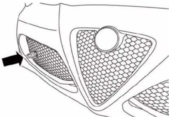
natural_image
Technical line drawing of a car front panel with mesh grating and a black arrow pointing to the side panel (no text or symbols)FrontTowEyeInstalled
When using a tow eye be sure to follow the "Tow Eye Usage Precautions" in this section.
WHATODOINEMERGENCIES237
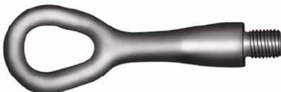
natural_image
Metallic mechanical component with a loop handle and threaded end (no text or symbols)TowEye
061409191
TowEyeUsagePrecautions
NOTE:
- Ensure that the tow eye is properly seated and secure in the mounting receptacle.
-
The tow eye is recommended for use with an approved tow bar and or rope.
-
Do not use the tow eye to pull the vehicle onto a flatbed truck.
- Do not use the tow eye to free a stuck vehicle. Refer to "Freeing A Stuck Vehicle" in this section for further information.
WARNING!
Standclearofvehicleswhenpullingwithtoweyes.
- Donotuseachainwithatoweye.Chainsmay break,causingseriousinjuryordeath.
- Donotuseatowstrapwithatoweye.Towstraps maybreakorbecomedisengaged,causingserious injuryordeath.
- Failuretofollowpropertoweyeusagemaycause componentstobreakresultinginseriousinjuryor death.
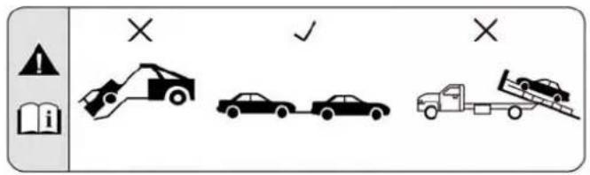
0614050352
TowEyeWarningLabel
| CAUTION! |
| • Thetoweyemustbeusedexclusivelyforroadside assistanceoperations.Onlyusethetoweyewithan appropriatedeviceinaccordancewiththehighway |
(Continued)
| CAUTION!(Continued) |
| code(arigidbarorrope)toflattowthevehicleforashortdistancetothenearestservicelocation.ToweyesMUSTNOTbeusedtotowvehiclesofftheroadorwherethereareobstacles.Incompliancewiththeaboveconditions,towingwithatoweyemusttakeplacewithtwovehicles(onetowing,theothertowed)alignedasmuchaspossiblealongthesamecenterline.Damagetoyourvehiclemayoccuriftheseguidelinesarenotfollowed. |
FIREEXTINGUISHER—IFEQUIPPED
The fire extinguisher is located under the dashboard in front of the passenger side seat.
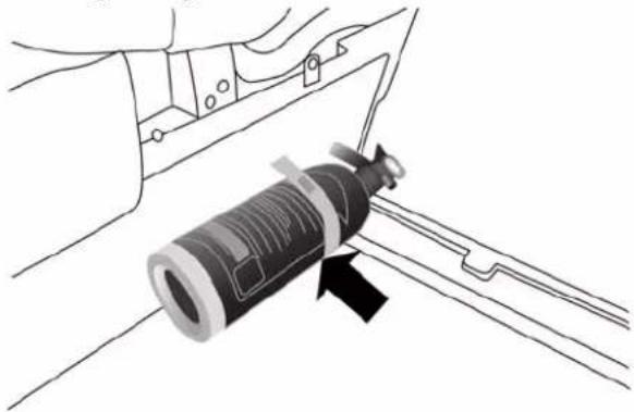
natural_image
Diagram of a mechanical device with a lever and handle, showing no text or symbolsFireExtinguisher
MAINTAINING YOUR VEHICLE
CONTENTS
■ENGINE COMPARTMENT — 1.750 TURBO . . .243
■ONBOARD DIAGNOSTIC SYSTEM — OBD II . .244
■REPLACEMENT PARTS....244
■DEALER SERVICE....245
■MAINTENANCE PROCEDURES....245
□Engine Oil. . . . . . . . . . . . . . . . . . . . . . . . . . . . . . . . . . . . . . . . . . . . . . . . . . . . . . . . . 246
□Engine Oil Filter....248
□Engine Air Cleaner Filter....248
□Engine Cover. . . . . . . . . . . . . . . . . . . . . . . . . . . . . . . . . . . . . . . . . . . . . . . . . . . . . . . . . . 249
□Maintenance-Free Battery .....250
□Air Conditioner Maintenance .....251
□Body Lubrication....252
□Wiper Blades....253
□Windshield Washer Nozzles .....255
□Adding Washer Solvent....256
□Exhaust System....259
□Cooling System....262
□Brake System....267
242 MAINTAINING YOURVEHICLE
□Alfa Twin Clutch Transmission .....272
□Appearance Care And Protection From Corrosion....273
■FUSES....281
□Engine Compartment Fuses....282
□Dashboard Fuse Box .....285
■VEHICLE STORAGE....286
■REPLACEMENT BULBS....287
■BULB REPLACEMENT....289
□Front Light Clusters....289
□Front Side Marker .....294
□Rear Light Clusters....295
□Direction Indicators....295
□Tail Lights/Brake Lights. . . . . . . . . . . . . . . . . . . . . . . . . . . . . . . . . . . . . . . . . . . 296
□Reversing Light....296
□Third Brake Lights....297
□License Plate Lights....298
□Roof Light....299
□Luggage Compartment Roof Light . . . . . . . . .300
■FLUID CAPACITIES....301
■FLUIDS, LUBRICANTS AND GENUINE P A R T S ....302
□Engine 302
□Chassis 303
ENGINECOMPARTMENT—1.750TURBO
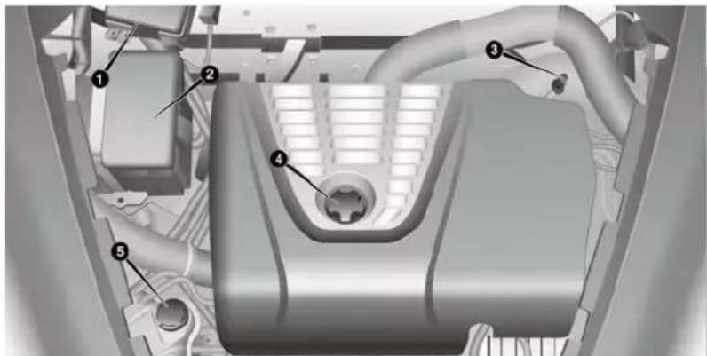
1 — Fuse Box 3 — Engine Oil Dip Stick 5 — Coolant Reservoir
2 — Battery 4 — Engine Oil Fill
ONBOARDDIAGNOSTICSYSTEM—OBDII
Your vehicle is equipped with a sophisticated onboard diagnostic system called OBD II. This system monitors the performance of the emissions, engine, and Alfa Twin Clutch Transmission control systems. When these systems are operating properly, your vehicle will provide excellent performance and fuel economy, as well as engine emissions well within current government regulations.
If any of these systems require service, the OBD II system will turn on the “Malfunction Indicator Light (MIL).” It will also store diagnostic codes and other information to assist your service technician in making repairs. Although your vehicle will usually be drivable and not need towing, see your authorized dealer for service as soon as possible.
CAUTION!
- ProlongeddrivingwiththeMILoncouldcause furtherdamagetotheemissioncontrolsystem.It couldalsoaffectfueleconomyanddriveability. Thevehiclemustbeservicedbeforeanyemissions testscanbeperformed.
- If the MIL is flashing while the engine is running, severecatalytic converter damage and power loss will soon occur. Immediately service is required.
REPLACEMENTPARTS
Use of genuine parts for normal/scheduled maintenance and repairs is highly recommended to ensure the designed performance. Damage or failures caused by the use of parts which are not quality-equivalent to genuine parts for maintenance and repairs will not be covered by the manufacturer's warranty.
DEALERSERVICE
Your authorized dealer has the qualified service personnel, special tools, and equipment to perform all service operations in an expert manner. Service Manuals are available which include detailed service information for your vehicle. Refer to these Service Manuals before attempting any procedure yourself.
NOTE: Intentional tampering with emissions control systems may void your warranty and could result in civil penalties being assessed against you.
WARNING!
Youcanbebadlyinjuredworkingonorarounda motorvehicle.Onlydoserviceworkforwhichyou havetheknowledgeandtheproperequipment.If
WARNING!(Continued)
youhaveanydoubtaboutyourabilitytoperforma servicejob, takeyourvehicletoacompetentmechanic.
MAINTENANCEPROCEDURES
The pages that follow contain the required maintenance services determined by the engineers who designed your vehicle.
Besides those maintenance items specified in the fixed maintenance schedule, there are other components which may require servicing or replacement in the future.
(Continued)
CAUTION!
- Failuretoproperlymaintainyourvehicleorperformrepairsandservicewhennecessarycould resultinmorecostlyrepairs,damagetoother componentsornegativelyimpactvehicleperformance.Immediatelyhavepotentialmalfunctions examinedbyanauthorizeddealerorqualified repaircenter.
- Yourvehiclehasbeenbuiltwithimprovedfluids thatprotecttheperformanceaddurabilityofyour vehicleandalsoallowextendedmaintenanceintervals.Donotusechemicalflushesinthesecomponentsasthechemicalscandamageyourengine, transmission,orairconditioning.Suchdamageis notcoveredbytheNewVehicleLimitedWarranty. Ifaflushisneededbecauseofcomponentmalfunction,useonlythespecifiedfluidfortheflushing procedure.
EngineOil
CheckingOilLevel
To assure proper engine lubrication, the engine oil must be maintained at the correct level. Check the oil level at regular intervals. The best time to check the engine oil level is before starting the engine after it has sat overnight.
Do not check oil level when the engine is warm. Checking engine oil level when the engine is warm will give you an incorrect reading.
Checking the oil while the vehicle is on level ground, and has sat overnight, will improve the accuracy of the oil level readings. Maintain the oil level between the range markings on the dipstick. The safe range is indicated by a crosshatch zone. Adding 1 quart of oil when the reading is at the low end of the indicated range will result in the oil level at the full end of the indicator range.
CAUTION!
Donotoverfilltheenginewithoil.Overfillingthe enginewithoilwillcauseoilaeration,whichcan leadtolossofoilpressureandanincreaseinoil temperature.Thislossofoilpressureandincreased oiltemperaturecoulddamageyourengine.
ChangeEngineOil
The oil change indicator system will remind you that it is time to take your vehicle in for scheduled maintenance. Refer to the "Maintenance Schedule" for further information.
NOTE: The actual interval for changing the oil and replacing the engine oil filter depends on the vehicle usage conditions and is signalled by the warning light or message (if present) on the instrument panel or every 12 months.
MAINTAINING YOUR VEHICLE247
EngineOilSelection
For best performance and maximum protection for turbocharged engines under all types of operating conditions, the manufacturer recommends synthetic engine oils that are API Certified and meet the requirements of Chrysler Material Standard MS-12991.
EngineOilViscosity—1.750TurboEngine(SAE Grade)
SAE 5W-40 full synthetic engine oil is recommended for all operating temperatures. This engine oil improves low temperature starting and vehicle fuel economy.
Lubricants which do not have both the engine oil certification mark and the correct SAE viscosity grade number should not be used.
The engine oil filler cap also shows the recommended engine oil viscosity for your engine. For information on
248MAINTAININGYOURVEHICLE
engine oil filler cap location, refer to "Engine Compartment" in "Maintaining Your Vehicle" for further information.
MaterialsAddedToEngineOil
The manufacturer strongly recommends against the addition of any additives (other than leak detection dyes) to the engine oil. Engine oil is an engineered product and its performance may be impaired by supplemental additives.
DisposingOfUsedEngineOilAndOilFilters
Care should be taken in disposing of used engine oil and oil filters from your vehicle. Used oil and oil filters, indiscriminately discarded, can present a problem to the environment. Contact your authorized dealer, service station or governmental agency for advice on how and where used oil and oil filters can be safely discarded in your area.
EngineOilFilter
The engine oil filter should be replaced with a new filter at every engine oil change.
EngineOilFilterSelection
This manufacturer's engines have a full-flow type disposable oil filter. Use a filter of this type for replacement. The quality of replacement filters varies considerably. Only high quality filters should be used to assure most efficient service. MOPAR® engine oil filters are high quality oil filters and are recommended.
EngineAirCleanerFilter
Refer to the "Maintenance Schedule" for the proper maintenance intervals.
WARNING!
Theairinductionsystem(aircleaner,hoses,etc.)can provide a measure of protection in the case of engine backfire. Donotremovetheairinduction system(air cleaner,hoses,etc.) unless such removal is necessary for repair or maintenance. Makes sure that no one is near the engine compartment before starting the vehicle with the air induction system(aircleaner, hoses,etc.) removed. Failure todos can result in serious personal injury.
EngineAirCleanerFilterSelection
The quality of replacement engine air cleaner filters varies considerably. Only high quality filters should be used to assure most efficient service. MOPAR® engine air cleaner filters are a high quality filter and are recommended.
EngineCover
To avoid possible damage to the engine cover, please disconnect each of the four mounting studs by pulling the engine cover upward, and then lift off the complete cover. Tilting the engine cover when one or more studs are still engaged will lead to premature failure of the couplers.
To reassemble the cover back onto the engine, first make sure it is properly aligned, the oil cap is centered, and that all four studs are lined up with their couplers. Then gently push on the four corners of the engine cover to snap the stud back into position.
No tools are required to remove or reassemble the engine cover.
Maintenance-FreeBattery
Your vehicle is equipped with a maintenance-free battery. You will never have to add water, nor is periodic maintenance required.
WARNING!
- Batteryfluidisacorrosiveacidsolutionandcan burnorevenblindyou.Donotallowbatteryfluid tocontactyoureyes,skin,orclothing.Donotlean overabatterywhenattachingclamps.Ifacid splashesineyesoronskin,flushtheareimmediatelywithlargeamountsofwater.Referto "Jump-StartingProcedures"in"WhatToDoIn Emergencies"forfurtherinformation.
- Batterygasisflammableandexplosive.Keep flameorsparksawayfromthebattery.Donotuse aboosterbatteryoranyotherboostersourcewith
WARNING!(Continued)
anoutputgreaterthan12Volts.Donotallowcable clampstotoucheachother.
- Batteryposts, terminals, and related accessories contain lead and lead compounds. Washhands after handling.
- Thebatteryinthisvehiclehasaventhosethat shouldnotbedisconnectedandshouldonlybe replacedwithabatteryofthesametype(vented).
CAUTION!
- It is essential when replacing the cables on the battery that the positive cable is attached to the positive post and then negative cable is attached to the negative post. Battery posts are marked positive (+) and negative (-) and are identified on the
CAUTION!(Continued)
batterycase.Cableclampsshouldbetightonthe terminalpostsandfreeofcorrosion.
- Ifa "fastcharger" is used while the battery is in the vehicle, disconnect both vehicle battery cables before connecting the charger to the battery. Donot use a "fastcharger" to provide starting voltage.
AirConditionerMaintenance
For best possible performance, your air conditioner should be checked and serviced by an authorized dealer at the start of each warm season. This service should include cleaning of the condenser fins and a performance test. Drive belt tension should also be checked at this time.
NOTE:
- Use only refrigerants and compressor lubricants approved by the manufacturer for your air conditioning system. Some unapproved refrigerants are flammable and can explode, injuring you. Other unapproved refrigerants or lubricants can cause the system to fail, requiring costly repairs. Refer to Warranty Information Book, located on the USB card, for further warranty information.
- The air conditioning system contains refrigerant under high pressure. To avoid risk of personal injury or damage to the system, adding refrigerant or any repair requiring lines to be disconnected should be done by an experienced technician.
CAUTION!
Donotusechemicalflushesinyourairconditioning systemasthechemicalscandamageyourairconditioningcomponents.Suchdamageisnotcoveredby theNewVehicleLimitedWarranty.
Refrigerant Recovery And Recycling HFO1234yf
HFO 1234yf Air Conditioning Refrigerant is a hydrofluorocarbon (HFC) that is endorsed by the Environmental Protection Agency and is an ozone-saving product with a low GWP (Global Warming Potential). However, the manufacturer recommends that air conditioning service be performed by authorized dealer or other service facilities using recovery and recycling equipment.
NOTE: Use only manufacturer approved A/C system PAG compressor oil, and refrigerants.
BodyLubrication
Locks and all body pivot points, including such items as seat tracks, door hinge pivot points and rollers, liftgate, tailgate, decklid, sliding doors and hood hinges, should be lubricated periodically with a lithium based grease, such as MOPAR® Spray White Lube to assure quiet, easy operation and to protect against rust and wear. Prior to the application of any lubricant, the parts concerned should be wiped clean to remove dust and grit; after lubricating excess oil and grease should be removed. Particular attention should also be given to hood latching components to ensure proper function. When performing other underhood services, the hood latch, release mechanism and safety catch should be cleaned and lubricated.
The external lock cylinders should be lubricated twice a year, preferably in the Fall and Spring. Apply a small amount of a high quality lubricant, such as MOPAR® Lock Cylinder Lubricant directly into the lock cylinder.
WiperBlades
Clean the rubber edges of the wiper blades and the windshield and rear window periodically with a sponge or soft cloth and a mild nonabrasive cleaner. This will remove accumulations of salt, waxes, or road film, and help reduce streaking and smearing.
Operation of the wipers on dry glass for long periods may cause deterioration of the wiper blades. Always use washer fluid when using the wipers to remove salt or dirt from a dry windshield or rear window.
Avoid using the wiper blades to remove frost or ice from the windshield or rear window. Make sure that they are not frozen to the glass before turning them on to avoid damaging the blade. Keep the blade rubber out of contact with petroleum products such as engine oil, gasoline, etc.
NOTE: Life expectancy of wiper blades varies depending on geographical area and frequency of use. Poor performance of blades may be present with chattering, marks, water lines or wet spots. If any of these conditions are present, clean the wiper blades or replace as necessary.
BladeLifting
If it is necessary to lift the blade from the windshield (In the event of snow or blade replacement) Proceed as directed:
- Rotate the end of the multifunction lever to the OFF position.
- Turn the ignition to the MAR-ON position then to STOP.
254MAINTAININGYOURVEHICLE
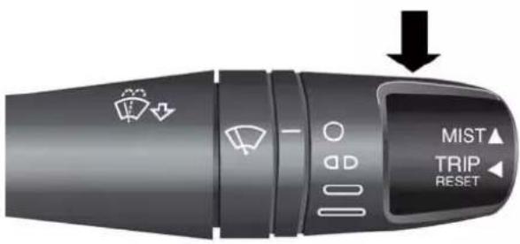
WindshieldWiper/WasherLever
- After turning the ignition to the STOP, within two minutes move the right stalk upward, into the unstable ("anti-panic") position, for at least half of a second. The windshield wiper then executes part of a stroke; at each command, approximately 1/3 of a normal wiper stroke is triggered.
NOTE: The previous operation can be repeated up to three times. In order to move the blades to the most suitable position.
- Lift the blade from the windshield and proceed with the required operation.
- Carefully lower the blade, bringing it back in contact with the windshield.
- Bring the blade to the initial rest position, turning the ignition to MAR-ON.
NOTE: Do not operate the screen wiper with the blades lifted from the windshield.
FrontWiperBladeRemoval/Installation
- Lift the front wiper arm upward to raise the wiper blade off of the windshield.
-
Press the release button on the arm of the wiper blade.
-
Push the wiper blade up the and remove it.
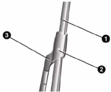
1 — WiperBlade
2 — Release Button
3 — WiperArm
- Install the wiper blade and firmly press the wiper blade until it snaps into place.
WindshieldWasherNozzles
The windshield washer nozzles are adjustable. They originally adjusted at the factory. Should it be necessary to adjust them again, contact your authorized Alfa Romeo Dealer.
If there is not jet of fluid, first check that there is fluid in the washer reservoir. Refer to "Adding Washer Solvent" in this section for further information.
Then check that the nozzle holes are not clogged; use a suitable tool such as a needle to unblock them if necessary.
256MAINTAININGYOURVEHICLE AddingWasherSolvent

natural_image
Top-down view of a car's head with two close-up views showing engine components (no text or symbols)1 — Brake Fluid Protection Panel
2 — Washer Solvent Protection Panel
To check the windshield washer solvent level, proceed as follows:
- To avoid any interference during the procedure, lift the windshield wiper blade.
- Loosen the four screws using the supplied screw-driver. Remove the washer solvent protection panel.
MAINTAINING YOUR VEHICLE257
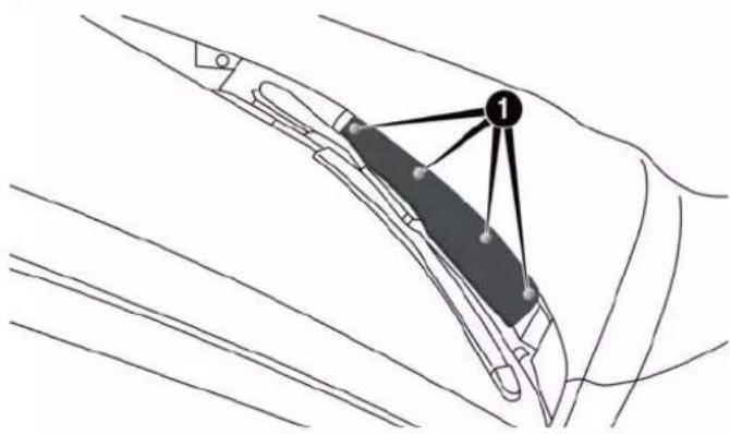
1 — Screw Locations
-
Release the plug from the opening.
-
Leaving the plug close to the opening, put a finger on the central hole in the plug and remove it: the level can be seen on the control pipe due to capillarity.
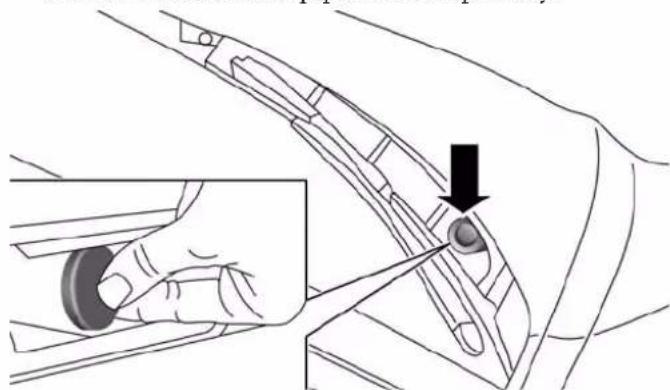
natural_image
Diagram of a hand operating a car interior with a hand valve and a black arrow indicating the handle (no text or symbols present)WasherSolventPlug
258MAINTAININGYOURVEHICLE
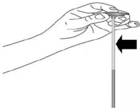
natural_image
Illustration of a hand holding a pen with an arrow pointing to it (no text or symbols present)WasherSolventDipStick
-
After the check, reinsert the plug with the control pipe in the initial position.
-
Reposition the washer solvent protection panel and tighten the four self-tapping screws.
If the level is not sufficient, namely if there is no washer solvent inside the pipe, proceed as follows:
-
To avoid any interference during the procedure, lift the windshield wiper blade.
-
Loosen the four screws using the supplied screw-driver. Remove the washer solvent protection panel.
-
Take the black funnel for topping up the windshield washer solvent and its extension pipe from the service kit in the luggage compartment.
-
Take out the plug with the solvent control pipe through the washer solvent protection panel.
-
Introduce the funnel and its extension pipe in the reservoir neck and top up.
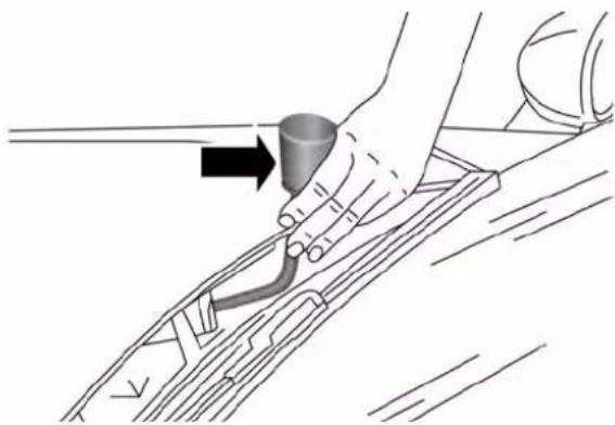
natural_image
Illustration of a hand holding a tool near a vehicle intake manifold (no text or symbols)WasherSolventFillFunnel
- After topping up, remove the funnel with the extension pipe.
- Refit the plug with the dipstick.
- Reposition the washer solvent protection panel and tighten the four self-tapping screws.
WARNING!
Commerciallyavailablewindshieldwashersolvents areflammable. They could ignite and burn you. Care must be exercised when filling or working around the washers solution.
ExhaustSystem
The best protection against carbon monoxide entry into the vehicle body is a properly maintained engine exhaust system.
If you notice a change in the sound of the exhaust system; or if the exhaust fumes can be detected inside the vehicle; or when the underside or rear of the vehicle is damaged; have an authorized technician inspect the complete exhaust system and adjacent body areas for broken, damaged, deteriorated, or mispositioned parts. Open seams or loose connections could permit exhaust fumes to seep into the passenger compartment. In addition, have the
exhaust system inspected each time the vehicle is raised for lubrication or oil change. Replace as required.
WARNING!
- Exhaustgasescaninjureorkill. They contain carbonmonoxide(CO), which is colorless and odorless. Breathing it can make you unconscious and can eventually poison you. To avoid breathing CO, refer to "Safety Tips/ExhaustGas" in "Things To Know Before Starting Your Vehicle" for further information.
- Ahotexhaustsystemcanstartafireifyoupark overmaterialsthatcanburn.Suchmaterialsmight begrassorleavescomingintocontactwithyour exhaustsystem.Donotparkoroperateyourvehicleinareaswhereyourexhaustsystemcancontactanythingthatcanburn.
CAUTION!
- The catalytic converter requires the use of unleaded fuel only. Leaded gasoline will destroy the effectiveness of the catalyst as an emissions control device and may seriously reduce engine performance and causes serious damage to the engine.
- Damagethecatalyticconvertercanresultifyour vehicleisnotkeptinproperoperatingcondition. Intheeventofenginemalfunction,particularly involvingenginemisfireorotherapparentlossof performance,haveyourvehicleservicedpromptly. Continuedoperationofyourvehiclewithasevere malfunctioncouldcausetheconvertertooverheat, resultinginpossibledamagetheconverterand vehicle.
Under normal operating conditions, the catalytic converter will not require maintenance. However, it is important to keep the engine properly tuned to assure proper catalyst operation and prevent possible catalyst damage.
NOTE: Intentional tampering with emissions control systems can result in civil penalties being assessed against you.
In unusual situations involving grossly malfunctioning engine operation, a scorching odor may suggest severe and abnormal catalyst overheating. If this occurs, stop the vehicle, turn off the engine and allow it to cool. Service, including a tune-up to manufacturer's specifications, should be obtained immediately.
To minimize the possibility of catalytic converter damage:
- Do not shut off the engine or interrupt the ignition, when the transmission is in gear and the vehicle is in motion.
- Do not try to start the engine by pushing or towing the vehicle.
- Do not idle the engine with any spark plug wires disconnected or removed, such as when diagnostic testing, or for prolonged periods during very rough idle or malfunctioning operating conditions.
CoolingSystem
WARNING!
- When working near the radiator cooling fan, disconnect the fan motor lead to turn the ignition switch to the OFF position. The fan is temperature controlled and can start at any time the ignition switch in the ON position.
- Youorotherscanbebadlyburnedbyhotengine coolant(antifreeze)orsteamfromyourradiator.If youseeorhearsteamcomingfromunderthehood, donotopenthehooduntiltheradiatorhashad timetocool.Nevertrytoopenacoolingsystem pressurecapwhentheradiatorishot.
CoolantChecks
Check engine coolant (antifreeze) protection every 12 months (before the onset of freezing weather, where
applicable). If the engine coolant (antifreeze) is dirty or rusty in appearance, the system should be drained, flushed and refilled with fresh engine coolant (anti-freeze). Check the front of the A/C condenser for any accumulation of bugs, leaves, etc. If dirty, clean by gently spraying water from a garden hose vertically down the face of the condenser.
CoolingSystem—Drain,FlushAndRefill
NOTE: Some vehicles require special tools to add coolant properly. Failure to fill these systems properly could lead to severe internal engine damage. If any coolant is needed to be added to the system please contact your local authorized dealer.
If the engine coolant (antifreeze) is dirty or contains visible sediment, have an authorized dealer clean and flush with OAT coolant (antifreeze) (conforming to MS.90032).
Refer to the "Maintenance Schedule" for the proper maintenance intervals.
SelectionOfCoolant
Refer to "Fluids, Lubricants, and Genuine Parts" in "Maintaining Your Vehicle" for further information.
CAUTION!
- Mixingofenginecoolant(antifreeze)otherthan specifiedOrganicAdditiveTechnology(OAT)enginecoolant(antifreeze),mayresultinengine damageandmaydecreasecorrosionprotection. OrganicAdditiveTechnology(OAT)enginecoolantisdifferentandshouldnotbemixedwith HybridOrganicAdditiveTechnology(HOAT)enginecoolant(antifreeze)orany"globallycompatible"coolant(antifreeze).Ifanon-OATengine
CAUTION!(Continued)
coolant(antifreeze)isintroducedintothecooling systeminanemergency,thecoolingsystemwill needtobedrained,flushed,andrefilledwithfresh OATcoolant(conformingtoMS.90032),byanauthorizeddealerassoonaspossible.
- Donotusewateraloneoralcohol-basedengine coolant(antifreeze)products.Donotuseadditional rustinhibitorsorantirustproducts,astheymaynot becompatiblewiththeradiatorenginecoolantand mayplugtheradiator.
- This vehicle has not been designed for use with propylene glycol-based engine coolant (antifreeze). Use of propylene glycol-based engine coolant (antifreeze) is not recommended.
(Continued)
264MAINTAININGYOURVEHICLE
AddingCoolant
Your vehicle has been built with an improved engine coolant (OAT coolant conforming to MS.90032) that allows extended maintenance intervals. This engine coolant (antifreeze) can be used up to ten years or 150,000 miles (240,000 km) before replacement. To prevent reducing this extended maintenance period, it is important that you use the same engine coolant (OAT coolant conforming to MS.90032) throughout the life of your vehicle.
Please review these recommendations for using Organic Additive Technology (OAT) engine coolant (antifreeze) that meets the requirements of Chrysler Material Standard MS.90032. When adding engine coolant (antifreeze):
- We recommend using MOPAR® Antifreeze/Coolant 10 Year/150,000 Mile Formula OAT (Organic Additive Technology) that meets the requirements of Chrysler Material Standard MS.90032.
- Mix a minimum solution of 50% OAT engine coolant that meets the requirements of Chrysler Material Standard MS.90032 and distilled water. Use higher concentrations (not to exceed 70% ) if temperatures below -34^(-37^) are anticipated.
- Use only high purity water such as distilled or deionized water when mixing the water/engine coolant (antifreeze) solution. The use of lower quality water will reduce the amount of corrosion protection in the engine cooling system.
Please note that it is the owner's responsibility to maintain the proper level of protection against freezing according to the temperatures occurring in the area where the vehicle is operated.
NOTE:
- Some vehicles require special tools to add coolant properly. Failure to fill these systems properly could lead to severe internal engine damage. If any coolant is needed to be added to the system please contact your local authorized dealer.
- Mixing engine coolant (antifreeze) types is not recommended and can result in cooling system damage. If HOAT and OAT coolant are mixed in an emergency, have a authorized dealer drain, flush, and refill with OAT coolant (conforming to MS.90032) as soon as possible.
CoolingSystemPressureCap
The cap must be fully tightened to prevent loss of engine coolant (antifreeze) and to ensure that engine coolant (antifreeze) will return to the radiator from the coolant recovery tank.
The cap should be inspected and cleaned if there is any accumulation of foreign material on the sealing surfaces.
WARNING!
- Donotopenhotenginecoolingsystem. Neveradd enginecoolant (antifreeze) when the engine is overheated. Donotloosenorremovethecaptocool anoverheated engine. Heat causes pressure to buildup in the coolingsystem. Topreventscalding or injury, donotremovethe pressure cap while the system is hot or under pressure.
- Donotuseapressurecapotherthantheone specified for your vehicle. Personal injury or enginedamagemayresult.
DisposalOfUsedEngineCoolant
Used ethylene glycol-based engine coolant (antifreeze) is a regulated substance requiring proper disposal. Check
266MAINTAININGYOURVEHICLE
with your local authorities to determine the disposal rules for your community. To prevent ingestion by animals or children, do not store ethylene glycol-based engine coolant in open containers or allow it to remain in puddles on the ground. If ingested by a child or pet, seek emergency assistance immediately. Clean up any ground spills immediately.
CoolantLevel
The coolant expansion bottle provides a quick visual method for determining that the coolant level is adequate. With the engine off and cold, the level of the engine coolant (antifreeze) in the bottle should be between the "MIN" and "MAX" marks.
As long as the engine operating temperature is satisfactory, the coolant bottle need only be checked once a month.
When additional engine coolant (antifreeze) is needed to maintain the proper level, it should be added to the coolant bottle. Do not overfill.
PointsToRemember
NOTE: When the vehicle is stopped after a few miles/kilometers of operation, you may observe vapor coming from the front of the engine compartment. This is normally a result of moisture from rain, snow, or high humidity accumulating on the radiator and being vaporized when the thermostat opens, allowing hot engine coolant (antifreeze) to enter the radiator.
If an examination of your engine compartment shows no evidence of radiator or hose leaks, the vehicle may be safely driven. The vapor will soon dissipate.
- Do not overfill the coolant expansion bottle.
- Check the coolant freeze point in the radiator and in the coolant expansion bottle. If engine coolant (anti-freeze) needs to be added, the contents of the coolant expansion bottle must also be protected against freezing.
- If frequent engine coolant (antifreeze) additions are required, the cooling system should be pressure tested for leaks.
- Maintain engine coolant (antifreeze) concentration at a minimum of 50% OAT coolant (conforming to MS-90032) and distilled water for proper corrosion protection of your engine which contains aluminum components.
- Keep the front of the radiator clean. If your vehicle is equipped with air conditioning, keep the front of the condenser clean.
- Do not change the thermostat for Summer or Winter operation. If replacement is ever necessary, install
ONLY the correct type thermostat. Other designs may result in unsatisfactory engine coolant (antifreeze) performance, poor gas mileage, and increased emissions.
BrakeSystem
In order to assure brake system performance, all brake system components should be inspected periodically. Refer to the “Maintenance Schedule” for the proper maintenance intervals.
WARNING!
Ridingthebrakescanleadtobrakefailureand possiblyacollision.Drivingwithyourfootrestingor ridingonthebrakepedalcanresultinabnormally highbraketemperatures,excessiveliningwear,and possiblebrakedamage.Ridingthebrakesmayalso reducebrakingcapacityinanemergency.
BrakeMasterCylinder
The fluid level in the master cylinder should be checked when performing under hood services, or immediately if the "Brake Warning Light" is on.
Be sure to clean the top of the master cylinder area before removing the cap. If necessary, add fluid to bring the fluid level up to the requirements described on the brake fluid reservoir. Fluid level can be expected to fall as the brake pads wear. The brake fluid level should be checked when the pads are replaced. However, low fluid level may be caused by a leak and a checkup may be needed.
Use only manufacturer's recommended brake fluid. Refer to "Fluids, Lubricants, and Genuine Parts" in "Maintaining Your Vehicle" for further information.
WARNING!
- Useonlymanufacturer's recommended brake fluid. Referto "Fluids, Lubricants, and Genuine Parts" in "Maintaining Your Vehicle" for further information. Using the wrong type of brake fluid can severely damage your brakes system and/or impair performance. The property of brake fluid for your vehicle is also identified on the original factory installed hydraulic master cylinder reservoir.
- To avoid contamination from foreign matter or moisture, use only new brake fluidor fluid thathas been in atightly closed container. Keep them master cylinder reservoir cap secured at all times. Brake fluidina open container absorbsmoisture from the air resulting in a lower boiling point. This may
(Continued)
WARNING!(Continued)
causeittoboilunexpectedlyduringhardorprolongedbraking,resultinginsuddenbrakefailure. Thiscouldresultinacollision.
• Overfillingthebrakefluidreservoircanresultin spillingbrakefluidonhotengineparts, causing thebrakefluidtocatchfire. Brakefluidcanalso damagepaintedandvinylsurfaces, careshouldbe takentoavoiditscontactwiththesesurfaces.
- Donotallowpetroleum-basedfluidtocontaminate thebrakefluid.Brakesealcomponentscouldbe damaged,causingpartialorcompletebrakefailure. Thiscouldresultinacollision.
CAUTION!
Useofimproperbrakefluidswillaffectoverall clutchsystemperformance.Improperbrakefluids maydamagetheclutchsystemresultinginlossof clutchfunctionandtheabilitytoshiftthetransmission.
270MAINTAININGYOURVEHICLE
CheckingBrakeFluid
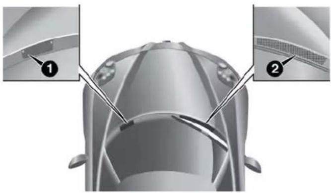
natural_image
Top-down view of a car's head and side panel showing structural details (no text or symbols)1 — Brake Fluid Protection Panel
2 — Washer Solvent Protection Panel
To check the brake fluid level, proceed as follows:
- Loosen the two screws and remove the brake fluid protection panel.
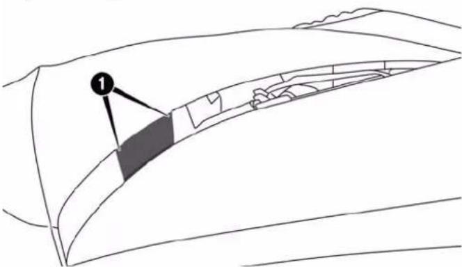
natural_image
Line drawing of a curved architectural structure with a labeled section (1), no text or symbols presentBrakeFluidProtectionPanel
1 — Screw Locations
- Check that the fluid is at the max. level.
- After checking, reposition the brake fluid protection panel and tighten the two screws.
AddingBrakeFluid
If the fluid level in the reservoir is not sufficient, proceed as follows:
- Take the black funnel for topping up the brake fluid and its extension pipe from the service kit in the luggage compartment.
- Loosen the reservoir plug and introduce the funnel with the extension pipe in the reservoir inlet.
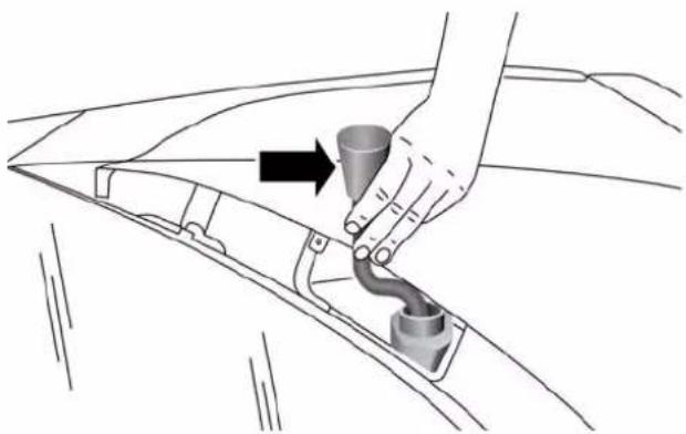
natural_image
Diagram of a hand holding a tool with a conical tip and pipe fitting, no text or symbols presentBrakeFluidFunnel
- After topping up, remove the funnel with the extension pipe.
- Tighten the reservoir plug.
- Reposition the brake fluid protection panel and tighten the two screws.
272MAINTAININGYOURVEHICLE
NOTE: Be very careful while removing the plug from the opening to prevent the plug from falling inside the vehicle body.
AlfaTwinClutchTransmission
SelectionOfLubricant
It is important to use the proper transmission fluid to ensure optimum transmission performance and life. Use only the manufacturer's specified transmission fluid. Refer to "Fluids, Lubricants, and Genuine Parts" in this section for fluid specifications. It is important to maintain the transmission fluid at the correct level using the recommended fluid. No chemical flushes should be used in any transmission; only the approved lubricant should be used.
CAUTION!
Usingatransmissionfluidotherthanthemanufac-turer'srecommendedfluidmaycausedeterioration intransmissionshiftquality. Referto "Fluids, Lubricants, and GenuineParts" in this section for fluid specifications.
SpecialAdditives
The manufacturer strongly recommends against using any special additives in the transmission.
Transmission fluid is an engineered product and its performance may be impaired by supplemental additives. Therefore, do not add any fluid additives to the transmission. The only exception to this policy is the use of special dyes for diagnosing fluid leaks.
CAUTION!
Donotusechemicalflushesinyourtransmissionas thechemicalscandamageyourtransmissioncomponents.SuchdamageisnotcoveredbytheNew VehicleLimitedWarranty.
FluidLevelCheck
The fluid level is preset at the factory and does not require adjustment under normal operating conditions. Routine fluid level checks are not required, therefore the transmission has no dipstick. Your authorized dealer can check your transmission fluid level using special service tools. If you notice fluid leakage or transmission malfunction, visit your authorized dealer immediately to have the transmission fluid level checked. Operating the vehicle with an improper fluid level can cause severe transmission damage.
CAUTION!
Ifatransmissionfluidleakoccurs,visityourauthorizeddealerimmediately.Severetransmissiondamagemayoccur.Yourauthorizeddealerhastheproper toolstoadjustthefluidlevelaccurately.
FluidChanges
Under normal operating conditions, the fluid installed at the factory will provide satisfactory lubrication for the life of the vehicle. However, change the fluid if it becomes contaminated (with water, etc.), or if the transmission is disassembled for any reason.
AppearanceCareAndProtectionFromCorrosion
ProtectionOfBodyAndPaintFromCorrosion
Vehicle body care requirements vary according to geographic locations and usage. Chemicals that make roads passable in snow and ice and those that are sprayed on
274MAINTAININGYOURVEHICLE
trees and road surfaces during other seasons are highly corrosive to the metal in your vehicle. Outside parking, which exposes your vehicle to airborne contaminants, road surfaces on which the vehicle is operated, extreme hot or cold weather and other extreme conditions will have an adverse effect on paint, metal trim, and under-body protection.
The following maintenance recommendations will enable you to obtain maximum benefit from the corrosion resistance built into your vehicle.
WhatCausesCorrosion?
Corrosion is the result of deterioration or removal of paint and protective coatings from your vehicle.
The most common causes are:
- Road salt, dirt and moisture accumulation.
- Stone and gravel impact.
• Insects, tree sap and tar.
- Salt in the air near seacoast localities.
- Atmospheric fallout/industrial pollutants.
Washing
- Wash your vehicle regularly. Always wash your vehicle in the shade using MOPAR® Car Wash, or a mild car wash soap, and rinse the panels completely with clear water.
- If insects, tar, or other similar deposits have accumulated on your vehicle, use MOPAR® Super Kleen Bug and Tar Remover to remove.
- Use a high quality cleaner wax, such as MOPAR® Cleaner Wax to remove road film, stains and to protect your paint finish. Take care never to scratch the paint.
- Avoid using abrasive compounds and power buffing that may diminish the gloss or thin out the paint finish.
NOTE: Hand washing is recommended. Avoid washing with power washers, or commercial car wash facilities.
CAUTION!
- Donotuseabrasiveorstrongcleaningmaterials suchassteelwoolorscouringpowderthatwill scratchmetalandpaintedsurfaces.
- Useofpowerwashersexceeding1,200psi(8274kPa) canresultindamageorremovalofpaintanddecals.
- If the engine compartment is washed with an high pressure jet, keep it at a distance of at least 8 inches (20 centimeters) from fillersurface.
MAINTAINING YOUR VEHICLE275
SpecialCare
- If you drive on salted or dusty roads or if you drive near the ocean, hose off the undercarriage at least once a month.
- It is important that the drain holes in the lower edges of the doors, rocker panels, and trunk be kept clear and open.
- If you detect any stone chips or scratches in the paint, touch them up immediately. The cost of such repairs is considered the responsibility of the owner.
- If your vehicle is damaged due to a collision or similar cause that destroys the paint and protective coating, have your vehicle repaired as soon as possible. The cost of such repairs is considered the responsibility of the owner.
276MAINTAININGYOURVEHICLE
- If you carry special cargo such as chemicals, fertilizers, de-icer salt, etc., be sure that such materials are well packaged and sealed.
- If a lot of driving is done on gravel roads, consider mud or stone shields behind each wheel.
- Use MOPAR® Touch Up Paint on scratches as soon as possible. Your authorized dealer has touch up paint to match the color of your vehicle.
WheelAndWheelTrimCare
All wheels and wheel trim, especially aluminum and chrome plated wheels, should be cleaned regularly using mild (neutral Ph) soap and water to maintain their luster and to prevent corrosion. Wash wheels with the same soap solution recommended for the body of the vehicle.
Your wheels are susceptible to deterioration caused by salt, sodium chloride, magnesium chloride, calcium chloride, etc., and other road chemicals used to melt ice or control dust on dirt roads. Use a soft cloth or sponge and mild soap to wipe away promptly. Do not use harsh chemicals or a stiff brush. They can damage the wheel's protective coating that helps keep them from corroding and tarnishing.
NOTE: Many aftermarket wheel cleaners contain strong acids or strong alkaline additives that can harm the wheel surface.
CAUTION!
Avoidproductsorautomaticcarwashesthatuse acidicsolutionsorstrongalkalineadditivesorharsh brushes. Theseproductsandautomaticcarwashes maydamagethewheel'sprotectivefinish.Such damageisnotcoveredbytheNewVehicleLimited Warranty.Onlycar wash soap,MOPARWheel Cleanerorequivalentisrecommended.
When cleaning extremely dirty wheels including excessive brake dust, care must be taken in the selection of tire and wheel cleaning chemicals and equipment to prevent damage to the wheels. Mopar Wheel Treatment or Mopar Chrome Cleaner or their equivalent is recommended or select a non-abrasive, non-acidic cleaner for aluminum or chrome wheels. Do not use any products on Dark Vapor or Black Satin Chrome Wheels. They will permanently damage this finish and such damage is not covered by the New Vehicle Limited Warranty.
CAUTION!
Donotusescouringpads,steelwool,abristlebrush, metalpolishesorovencleaner. Theseproductsmay damagethewheel'sprotectivefinish.Suchdamageis notcoveredbytheNewVehicleLimitedWarranty. Onlycarwashsoap,MOPARWheelCleanerorequivalentisrecommended.
NOTE: If you intend parking or storing your vehicle for an extended period after cleaning the wheels with wheel cleaner, drive your vehicle for a few minutes before doing so. Driving the vehicle and applying the brakes when stopping will reduce the risk of brake rotor corrosion.
DarkVaporOrBlackSatinChromeWheels
CAUTION!
If your vehicle is equipped with Dark Vaporor Black Satin Chromewheels DONOTUSEwheel cleaners, abrasives or polishing compounds. They will permanently damage this finish and such damage is not covered by the New Vehicle Limited Warranty. USE ONLY MILDSOAP AND WATER WITH ASOFT CLOTH. Used on a regular basis; this is all that is required to maintain this finish.
278MAINTAININGYOURVEHICLE
StainRepelFabricCleaningProcedure—If Equipped
Stain Repel seats may be cleaned in the following manner:
- Remove as much of the stain as possible by blotting with a clean, dry towel.
- Blot any remaining stain with a clean, damp towel.
- For tough stains, apply MOPAR® Total Clean, or a mild soap solution to a clean, damp cloth and remove stain. Use a fresh, damp towel to remove soap residue.
- For grease stains, apply MOPAR® Multi-Purpose Cleaner to a clean, damp cloth and remove stain. Use a fresh, damp towel to remove soap residue.
- Do not use any harsh solvents or any other form of protectants on Stain Repel products.
InteriorCare
Use MOPAR® Total Clean to clean fabric upholstery and carpeting.
Use MOPAR® Total Clean to clean vinyl upholstery.
MOPAR® Total Clean is specifically recommended for leather upholstery.
Your leather upholstery can be best preserved by regular cleaning with a damp soft cloth. Small particles of dirt can act as an abrasive and damage the leather upholstery and should be removed promptly with a damp cloth. Stubborn soils can be removed easily with a soft cloth and MOPAR® Total Clean. Care should be taken to avoid soaking your leather upholstery with any liquid. Please do not use polishes, oils, cleaning fluids, solvents, detergents, or ammonia-based cleaners to clean your leather upholstery. Application of a leather conditioner is not required to maintain the original condition.
WARNING!
Donotusevolatilesolventsforcleaningpurposes. Manyarepotentiallyflammable,andifusedin closedareastheymaycauserespiratoryharm.
CAUTION!
DonotuseAlcoholandAlcohol-basedand/orKeton basedcleaningproductstocleanleatherseats, as damagetheseatmayresult.
CleaningHeadlights
Your vehicle has plastic headlights that are lighter and less susceptible to stone breakage than glass headlights.
Plastic is not as scratch resistant as glass and therefore different lens cleaning procedures must be followed.
To minimize the possibility of scratching the lenses and reducing light output, avoid wiping with a dry cloth. To remove road dirt, wash with a mild soap solution followed by rinsing.
Do not use abrasive cleaning components, solvents, steel wool or other aggressive material to clean the lenses.
GlassSurfaces
All glass surfaces should be cleaned on a regular basis with MOPAR®, or any commercial household-type glass cleaner. Never use an abrasive type cleaner. Use caution when cleaning the inside rear window equipped. Do not use scrapers or other sharp instrument that may scratch the elements.
Labels can be peeled off after soaking with warm water (If Equipped), keep all objects a safe distance from the windows.
When cleaning the rear view mirror, spray cleaner on the towel or rag that you are using. Do not spray cleaner directly on the mirror.
InstrumentPanelCover
The instrument panel cover has a low glare surface which minimizes reflections on the windshield. Do not use protectants or other products which may cause undesirable reflections. Use soap and warm water to restore the low glare surface.
InstrumentPanelBezels
CAUTION!
When installing hanging air fresheners in your vehicle, read the installation instructions carefully. Some air fresheners will damage the finish of painted or decorated parts if allowed to directly contact an surface.
CleaningPlasticInstrumentClusterLenses
The lenses in front of the instruments in this vehicle are molded in clear plastic. When cleaning the lenses, care must be taken to avoid scratching the plastic.
- Clean with a wet soft rag. A mild soap solution may be used, but do not use high alcohol content or abrasive cleaners. If soap is used, wipe clean with a clean damp rag.
- Dry with a soft cloth.
SeatBeltMaintenance
Do not bleach, dye or clean the belts with chemical solvents or abrasive cleaners. This will weaken the fabric. Sun damage can also weaken the fabric.
If the belts need cleaning, use a mild soap solution or lukewarm water. Do not remove the belts from the car to wash them. Dry with a soft cloth.
Replace the belts if they appear frayed or worn or if the buckles do not work properly.
WARNING!
Afrayedortornbeltcouldripapartinacollisionand leaveyouwithnoprotection.Inspectthebeltsystem periodically,checkingforcuts,frays,orlooseparts. Damagedpartsmustbereplacedimmediately.Do notdisassembleormodifythesystem.Seatbelt assembliesmustbereplacedafteracollisionifthey havebeendamaged(i.e.,bentretractor,tornwebbing,etc.).
MAINTAININGYOURVEHICLE281
FUSES
WARNING!
- Whenreplacingablownfuse,alwaysuseanappropriatereplacementfusewiththesameamp ratingastheoriginalfuse.Neverreplaceafuse withanotherfuseofhigheramprating.Never replaceablownfusewithmetalwiresoranyother material.Failurerouseproperfusesmayresultin seriouspersonalinjury,fireand/orpropertydamage.
- Beforereplacingafuse, makesurethattheignition isoffandthatalltheotherservicesareswitchedoff and/ordisengaged.
- Ifthereplacedfuseblowsagain,contactanaauthorizeddealer.
(Continued)
282MAINTAININGYOURVEHICLE
WARNING!(Continued)
- Ifageneralprotectionfuseforsafetysystems(air bagsystem,brakingsystem),powerunitsystems (enginesystem,gearboxsystem)orsteeringsystem blows,contactanauthorizeddealer.
EngineCompartmentFuses
The engine compartment fuse box is located on the left side of the engine compartment, next to the battery. To access the fuses, remove screws and then remove the cover.
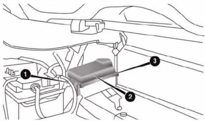
EngineCompartmentFuseBox
1 — Forward Screw
2 — Fuse Box Cover
3 — Rearward Screw
The ID number of the electrical component corresponding to each fuse can be found on the back of the cover.
| CavityMaxiFuseMiniFuseDescription | |||
| F01 70 Amp | Tan Body Controller | ||
| F03 20 Amp | Yellow Ignition Switch | ||
| F04 40 Amp | Orange Anti-Lock Brake | Pump | |
| F05 20 Amp | Yellow Anti-Lock Brake | Valve | |
| F06 40 Amp | Orange Radiator Fan - Low Speed | ||
| F07 50 Amp | Red Radiator Fan - High Speed | ||
| F08 20 Amp | Yellow Blower Motor | ||
| F09 5 Amp | Tan Headlight beam switch (If Equipped) | ||
| F10 | 10 Amp Red | Horn | |
| F11 | 20 Amp Yellow | Powertrain | |
| F14 | 15 Amp Blue | Alfa Twin Clutch Transmission | |
| F15 | 15 Amp Blue | Alfa Twin Clutch Transmission | |
| F16 5 Amp | Tan Alfa Twin Clutch Transmission, ECM | ||
| F17 | 10 Amp Red | Powertrain | |
| F18 5 Amp | Tan Powertrain | ||
| F19 7.5 Amp | Brown Air Conditioning | Compressor | |
| F21 20 Amp | Yellow Fuel Pump | ||
| F22 20 Amp | Yellow Engine Control Unit Power Supply | ||
| F24 5 Amp | Tan Anti-Lock Brake System (ABS) | ||
| F30 10 Amp | Red Water Pump, HVAC | ||
| F82 30 Amp | Green Headlamp Washer (If Equipped) | ||
| F83 | 40 Amp Orange | Alfa Twin Clutch Transmission Pump | |
| F84 5 Amp | Tan After Run Pump | ||
| F86 | 15 Amp Blue | Rear Power Outlet 12V | |
| F88 7.5 Amp | Brown Heated Mirrors | ||
DashboardFuseBox
The dashboard fuse box is part of the Body Control Module (BCM) and is located on the passenger side under the forward passenger floor. Remove the six screws and the forward floor pan to access the BCM.
| CavityVehicleFuseNumberMiniFuseDescription | |||
| 3 F53 7 | 5 Amp Brown Instrument | Panel Node | |
| 4 F38 15 | 5 Amp Blue Central Door Locking | ||
| 5 F36 10 | Amp Red Diagnostic Socket, Car Radio, TPMS, Alarm | ||
| 6 F43 | 20 Amp Yellow Bi-Directional Washer | ||
| 7 F48 | 20 Amp Yellow Passenger Power Window | ||
| 9 F50 7 | 5 Amp Brown Airbag | ||
| 10 | F51 7.5 Amp Brown Headlamp Washer | Relay, A/C Compressor Relay, High Beam Relay, Parking ECU, Car Radio, Stop Lamp Switch | |
| 11 | F37 7.5 Amp Brown Stop Light Switch, Instrument Panel Node | ||
| 12 F49 | 5 Amp Tan Transmission Shifter Module, Cigar Light | Light, Drive Style Unit, Heated Mirrors Relay | |
| 13 F31 | 5 Amp Tan Climate Control, Body Controller | ||
| 14 F47 | 20 Amp Yellow Driver Power Window | ||
VEHICLESTORAGE
If you are leaving your vehicle dormant for more than 21 days, you may want to take these steps to protect your battery.
- Disconnect the negative cable from the battery.
- Anytime you store your vehicle, or keep it out of service (e.g., vacation) for two weeks or more, run the air conditioning system at idle for about five minutes in the fresh air and high blower setting. This will ensure adequate system lubrication to minimize the possibility of compressor damage when the system is started again.
REPLACEMENTBULBS
InteriorBulbs
| BulbNumber | |
| Overhead Lamp C10W | |
| Luggage Compartment W5W |
ExteriorBulbs
| BulbNumber | |
| Parking Lights/Daytime Running Lights (DRL) LED (See | Authorized dealer) |
| Rear Tail Lights LED (See Authorized dealer) | |
| Font and Rear Side Lights W3W | |
| Dipped/Main Beam Headlights (Versions With Bi-Halogen Headlights) — If Equipped | HIR2 |
| Dipped/Main Beam Headlights (Versions With Bi-Xenon Headlights) — If Equipped | D5S (See Authorized dealer) |
288MAINTAININGYOURVEHICLE
| BulbNumber | |
| Dipped/Main Beam Headlights (Versions With Bi-Led Headlights) — If Equipped | LED (See Authorized dealer) |
| Front Direction Indicators PY24W | |
| Rear Direction Indicators P21W | |
| Side Direction Indicators WY5W | |
| Brake Lights LED (See Authorized dealer) | |
| Third Brake Light LED (See Authorized dealer) | |
| License Plate Lamps W5W | |
| Reversing light W16W | |
| NOTE:Numbers refer to commercial bulb types that can be purchased from your authorized dealer. | |
| If a bulb needs to be replaced, visit your authorized dealer or refer to the applicable Service Manual. | |
MAINTAININGYOURVEHICLE289
BULBREPLACEMENT
NOTE:Lens fogging can occur under certain atmospheric conditions. This will usually clear as atmospheric conditions change to allow the condensation to change back into a vapor. Turning the lamps on will usually accelerate the clearing process.
FrontLightClusters
The front head lamp contains bulbs for the parking lights/daytime running lights (DRL), low beam headlights, high beam headlights and direction indicators.
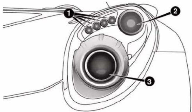
1 — Daytime Running Lights
2 — Direction Indicator
3 — High/Low Beam Lights
If bulb replacement is required, please see an authorized dealer.
290MAINTAININGYOURVEHICLE
SideLights/DaytimeRunningLights(DRL)
These are LEDs. For the replacement, contact the your authorized dealer.
Low/HighBeamBi-HalogenHeadlights
To change the bulb, proceed as follows:
- Turn the steering wheel completely.
- Open the protective flap by rotating the screw.
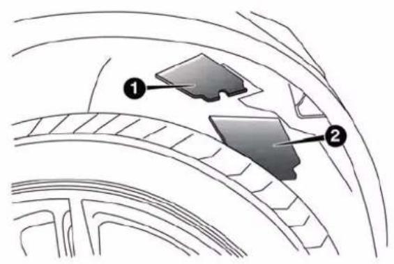
1 — Direction Indicator Bulb Protective Flap
2 — Headlamp Bulb Protective Flap
- Remove the electric connector (1) and then rotate the bulb holder (2) clockwise and remove it.
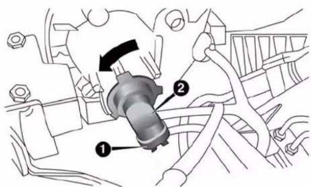
1 — Electrical Connector
2 — Bulb Holder
- Extract the bulb and replace it.
MAINTAINING YOUR VEHICLE291
- Refit the new bulb, making sure that it is locked correctly, and reconnect the electrical connector.
- Close the protective flap.
Low/HighBeamHID&LEDHeadlights
For the replacement, contact the your authorized dealer.
DirectionIndicators
Front:
- Turn the steering wheel completely.
- Open the protective flap by rotating the screw.
292MAINTAININGYOURVEHICLE
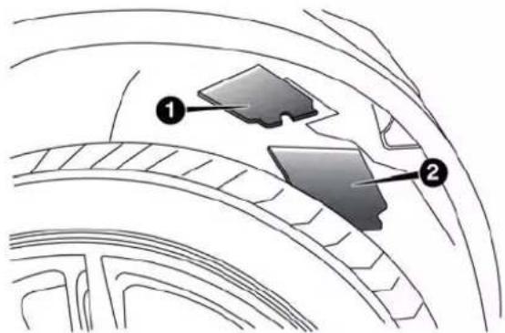
1 — Direction Indicator Bulb Protective Flap
2 — Headlamp Bulb Protective Flap
-
Rotate the bulb holder counterclockwise and remove it.
-
Rotate the bulb assembly counter clockwise to remove from bulb holder.
-
Install the new bulb, making sure that it is locked in correctly, and reinstall into headlamp assembly.
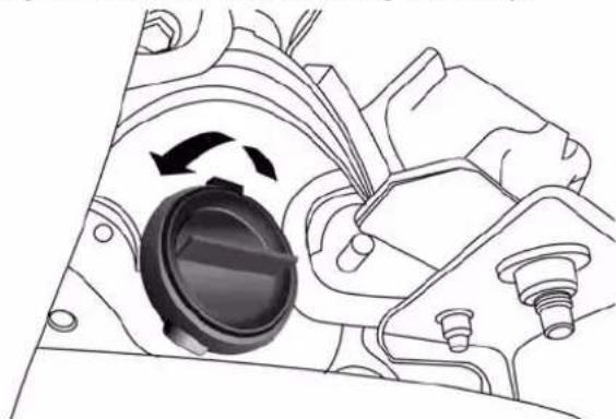
natural_image
Mechanical assembly diagram showing a rotating component with directional arrows (no text or labels)BulbHolder
- Close the protective flap.
Side:
MAINTAININGYOURVEHICLE293
- Adjust the lens in the point shown in to compress the retaining clip, then pull the cluster outwards.
- Turn the bulb holder counterclockwise, remove the bulb and replace it.
- Install the bulb holder in the lens and turn it clockwise.
- Install the cluster making sure that the internal clip clicks into position.
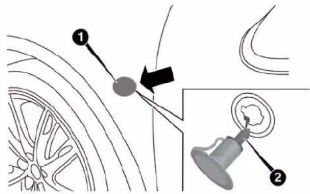
1 — Lens
2 — Bulb Holder
294MAINTAININGYOURVEHICLE
FrontSideMarker
To change the bulb, proceed as follows:
- Turn the front wheels to gain access and then remove the fastener from the inner wheel liner.
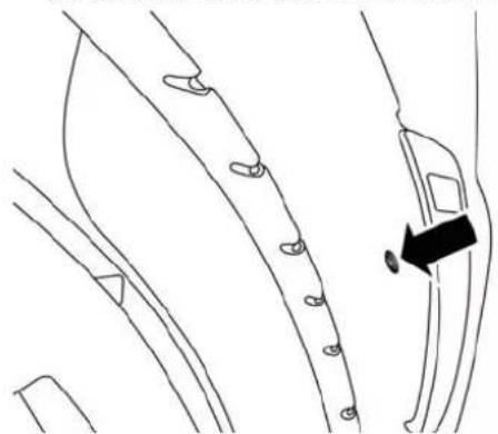
natural_image
Line drawing of a curved mechanical component with mounting holes and a black arrow indicating a detail (no text or symbols)FastenerLocation
- Fold back wheel liner door to access bulb housing.
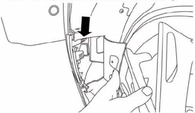
natural_image
Line drawing of a mechanical component with a black arrow pointing to a detail (no text or symbols)BulbHousingLocation
- Remove bulb from bulb housing then remove and replace bulb and reinstall.
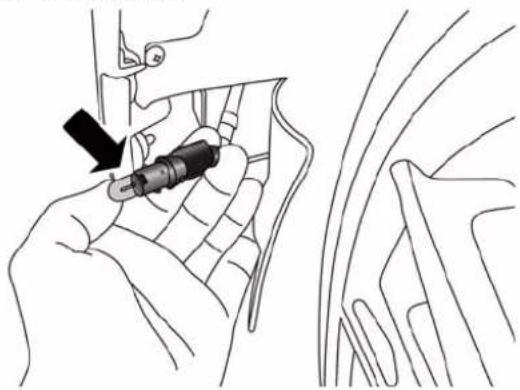
natural_image
Illustration of a hand holding a small mechanical component, with no visible text or symbolsFrontSideMarkerBulb
RearLightClusters
These contain the bulbs for the side lights, direction indicators and brake lights.
DirectionIndicators
To change the bulb, proceed as follows:
- Remove the protective cap (one for each side) on the side cover of the luggage compartment.
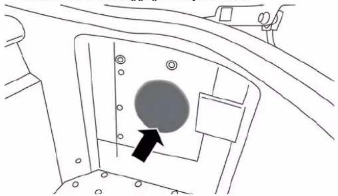
natural_image
Diagram of a vehicle interior showing a circular component with an arrow pointing to it, no text or symbols present.FirstProtectiveCap
296MAINTAININGYOURVEHICLE
- Remove the second protective cap inserting a hand inside the opening.
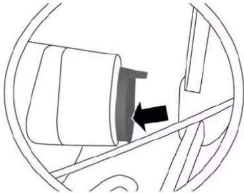
natural_image
Diagram of a car interior showing a seatbelt with an arrow indicating direction (no text or symbols)SecondProtectiveCap
-
Rotate clockwise to remove the bulb holder remove the bulb from the bulb holder.
-
Install the bulb by pressing it into bulb holder then turn install the bulb holder and turn it counterclockwise.
- Install the previously removed protective caps.
TailLights/BrakeLights
These are LEDs. For the replacement, contact the your local dealer.
ReversingLight
WARNING!
Thereversinglightarelocatedclosetotheexhaust pipes;taketheutmostcarenottogetburntduring thebulbreplacement.
To replace the reversing lights turn the bulb holder counterclockwise, remove the bulb and replace it.
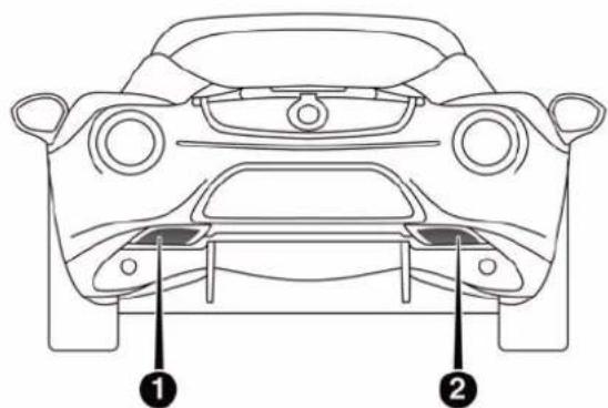
1 — Reverse Light Location 2 — Reverse Light Location
MAINTAININGYOURVEHICLE297
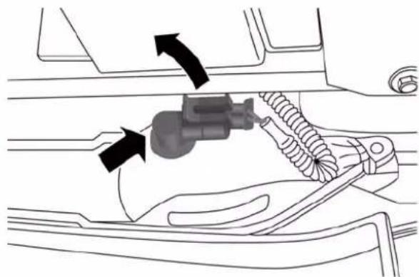
natural_image
Mechanical assembly diagram showing a connector inserted into a car body with directional arrows indicating motion (no text or labels)ReversingLightBulbHolder
ThirdBrakeLights
These are LEDs. For the replacement, contact your local dealer.
298MAINTAININGYOURVEHICLE
LicensePlateLights
To replace the bulbs proceed as follows:
- Position the lens in the point shown laterally to compress the retaining clip, then pull the license plate light cluster out.
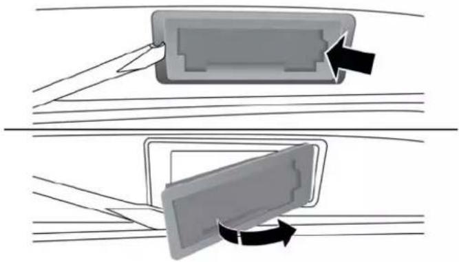
natural_image
Diagram showing two steps of a device component being inserted into a housing, with arrows indicating the process (no text or symbols present)LicensePlateLampRemoval
- Turn bulb holder (1) counterclockwise, remove bulb (2) and replace it.
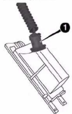
natural_image
Technical line drawing of a mechanical component with a threaded rod and labeled part (1), no readable text or symbols present.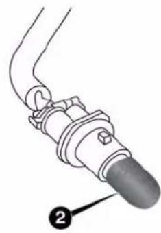
natural_image
Mechanical component diagram showing a curved pipe fitting with a labeled pin (no text or symbols present)1 — Bulb Holder
2 — Bulb
MAINTAININGYOURVEHICLE299
RoofLight
To change the bulb, proceed as follows:
- Remove roof light working at the points indicated by the arrows.
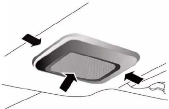
natural_image
Diagram showing a rectangular object with internal patterns and directional arrows, connected to a wire (no text or symbols)RoofLight
- Open protective flap (2) and replace bulb (1), releasing it from the side contacts. Make sure that the new bulb is correctly secured between the contacts.
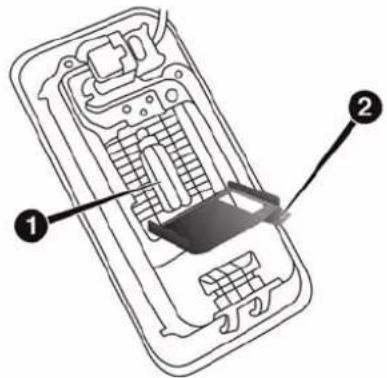
1 — Bulb
2 — Protective Flap
300MAINTAININGYOURVEHICLE
- Close protective flap (2) and install roof light in its housing, making sure that it is locked in place.
LuggageCompartmentRoofLight
To replace the bulb, proceed as follows:
- Open the luggage compartment and remove luggage compartment roof light, working in the direction shown by the arrow.
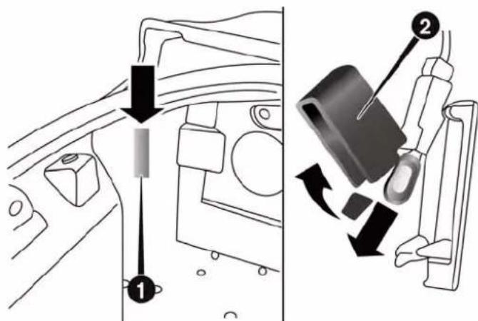
1 — Light Cover
2 — Light Protector
2. Open light protector (2) and replace the bulb.
3. Close protector on the lens.
- Install luggage compartment roof light by inserting it in its correct position, first on one side and then pressing on the other side until it clicks into place.
FLUIDCAPACITIES
| U.S.Metric | ||
| Fuel(Approximate) | ||
| 1.750 Turbo Engine 10.5 Gallons 40 Liters | ||
| Reserve Fuel 1.1 Gallons 4 Liters | ||
| EngineOilwithFilter | ||
| 1.750 Turbo Engine 6.1 Quarts 5.8 Liters | ||
| CoolingSystem | ||
| 1.750 Turbo Engine (MOPAR® Antifreeze/Engine Coolant 10 Year/150,000 Mile Formula). | 11.2 Quarts 10.6 Liters |
FLUIDS, LUBRICANTSANDGENUINEPARTS
Engine
| ComponentFluid,Lubricant,orGenuinePart | |
| Engine Coolant - 1.750 Turbo Engine We recommend you use MOPAR® Antifreeze/Coolant10 Year/150,000 Mile Formula OAT (Organic Additive Technology) or equivalent meeting the requirements of Chrysler Material Standard MS.90032. | |
| Engine Oil - 1.750 Turbo Engine We recommend you use SAE 5W-40 API CertifiedSynthetic Engine Oil, meeting the requirements of Chrysler Material Standard MS-12991. Refer to your engine oil filler cap for correct SAE grade. | |
| Engine Oil Filter - 1.750 Turbo Engine We recommend you use MOPAR® Engine Oil Filter. | |
| Spark Plugs - 1.750 Turbo Engine We recommend you use MOPAR® Spark Plugs. * | |
| Fuel Selection - 1.750 Turbo Engine | Use Only 91 Octane or higher. |
NOTE:* The following are essential to ensure correct operation and prevent serious damage to the engine: only use spark plugs of the same make and type which are specially certified for such engines strictly comply with the spark plug replacement interval given in the maintenance schedule. For spark plug replacement, it is advisable to contact the dedicated Alfa Romeo Dealership. Refer to the “Maintenance Schedule” section for the required spark plug intervals.
Chassis
| ComponentFluid,Lubricant,orGenuinePart | |
| Alfa Twin Clutch Transmission Gear Oil: Use Castrol BOT402Control System: MOPAR® C Series DDCT SAE 75W Hydraulic Fluid or equivalent. | |
| Brake Master Cylinder We recommend you use MOPAR® | DOT 4. If DOT 4brake fluid is not available, then DOT 3 is acceptable. |
MAINTENANCESCHEDULES
CONTENTS
■ MAINTENANCE SCHEDULE .....306 □ Maintenance Chart .....309
306MAINTENANCESCHEDULES
MAINTENANCESCHEDULE
Your vehicle is equipped with an automatic oil change indicator system. The oil change indicator system will remind you that it is time to take your vehicle in for scheduled maintenance.
Based on engine operation conditions, the oil change indicator message will illuminate in the instrument cluster. This means that an engine oil and engine oil filter change is required for your vehicle. Operating conditions such as frequent short-trips, trailer tow, extremely hot or cold ambient temperatures, and E85 fuel usage will influence when the “Change Oil” or “Oil Change Required” message is displayed. Severe Operating Conditions can cause the change oil message to illuminate as early as 3,500 miles (5,600 km) since last reset. Have your vehicle serviced as soon as possible, within the next 500 miles (805 km).
The Wrench Warning Light may appear in the cluster as a service reminder when vehicle maintenance is required, according to the scheduled maintenance mileage. The maintenance schedule intervals are set by the manufacturer. Failure to have them carried out may void your New Vehicle Warranty.
NOTE: The actual interval for changing the oil and replacing the engine oil filter depends on the vehicle usage conditions and is signalled by the warning light or message (if present) on the instrument panel or every 12 months.
SevereDutyAllModels
In addition, if your vehicle is used under demanding conditions, including:
- On the track
- On dusty roads
MAINTENANCESCHEDULES307
- Short, repeated trips (less than 4-5 miles or 7-8 km) at sub-zero temperatures
- Allowing the engine to idle for extended periods of time
- Driving for long distances at low speeds
- Allowing the vehicle to sit for long periods of inactivity
Under any of the above circumstances, the following checks need to be performed more frequently than indicated in the Maintenance Schedule: - Check front and rear disc brake pad condition and wear
- Check cleanliness of tailgate locks.
- Check cleanliness and lubrication of chassis and steering linkage
-
Visually inspect condition of: engine, gearbox, transmission, pipes and hoses (exhaust - fuel system - brakes) and rubber elements (gaiters - sleeves - bushes - etc.)
-
Check battery charge and battery fluid level (electrolyte)
- Visually inspect condition of the auxiliary drive belts
- Check and, if necessary, change engine oil and replace oil filter
- Check and, if necessary, replace air cleaner
Using the car on track should be regarded as an exception. The car has been designed and produced for road use.
Change Engine Oil at 4000 miles (6,500 km) if the vehicle is operated in a dusty and off road environment. This type of vehicle use is considered Severe Duty.
If the vehicle is operated in a dusty or dirty environment the engine air filter has to be changed every 6500 miles (10,000 km).
308MAINTENANCESCHEDULES
OnceAMonthOrBeforeALongTrip/PeriodicChecks
Every 600 miles (1,000 km) or before long trips, check and, if necessary, top off the following:
- Check engine oil level
- Check brake fluid level
- Check windshield washer fluid level
- Check the tire inflation pressures and look for unusual wear or damage
- Check the fluid levels of the coolant reservoir and brake master cylinder reservoir, and add as needed
- Check function of all interior and exterior lights
- Check screen wash/wipe system and positioning/wear of windscreen
Every 2000 miles (3000 km) check and, if necessary, top up: engine oil level
RequiredMaintenanceIntervals
Refer to the maintenance schedules on the following page for the required maintenance intervals.
| AtEveryOilChangeIntervalAsIndicatedByOil ChangeIndicatorSystem: |
| Change oil and filter. |
| Inspect battery and clean and tighten terminals as required. |
| Inspect brake pads, shoes, rotors, drums, and hoses. |
| Inspect engine cooling system protection and hoses. |
| Check and adjust hand brake. |
| Inspect exhaust system. |
| Inspect engine air cleaner if using in dusty or off-road conditions. |
MaintenanceChart
| Mileageortimepassed(whichevercomesfirst) | 12,000 | 24,000 | 36,000 | 48,000 | 60,000 | 72,000 |
| OrMonths:1 | 2243648 | 6072 | ||||
| OrKilometers: | 20,000 | 40,000 | 60,000 | 80,000 | 100,000 | 120,000 |
| Checkbatterychargestatusandpossiblyrecharge X XX | X | X | X | |||
| Checktirecondition/wearandadjustpressureifrequiredXXXXXX | ||||||
| Checklightingsystemoperation(headlights,directionindicators,hazard lights,passengercompartmentlights,bootlights,instrumentpanel warninglights,etc.) | X | X | X | X | ||
| Checkvehiclefasteners | X | X | X | |||
| Checkmechanicalcomponentsfasteners | XXXXXX | |||||
| Checkwindscreenwiper/washeroperation,adjustnozzles | XXXXXX | |||||
| Checkposition/wearofwindscreenwiperblade | XXXXXX | |||||
310MAINTENANCESCHEDULES
| Mileageortimepassed(whichevercomesfirst) | 12,000 | 24,000 | 36,000 | 48,000 | 60,000 | 72,000 |
| OrMonths:1 | 2243648 | 6072 | ||||
| OrKilometers: | 20,000 | 40,000 | 60,000 | 80,000 | 100,000 | 120,000 |
| Checkcleanlinessofhoodanddecklidlocks,aswellascleanliness andlubricationofassociatedlinkages | X | X | X | X | ||
| Visuallyinspectconditionof:exteriorbodywork,carbonmonocoque, aerodynamicbottom,pipesandhoses(exhaust,fuelsupplysystem, brakes),rubberelements(boots,driveshaftboots,sleeves,bushes,etc.) | X | X | X | X | ||
| Checkconditionandwearoffrontbrakepadsanddiscs,andoperation ofpadwearindicator | X | X | X | X | ||
| Checkconditionandwearofrearbrakepadsanddiscs,andoperation ofpadwearindicator | X | X | X | X | ||
| Checkandtopoff,ifrequired,fluidlevels(enginecoolant,brake/ hydraulicclutchfluid,windscreenwasherfluid,batteryfluid,etc) | X | X | X | X | ||
| Visuallyinspecttheconditionofaccessorydrivebelt(s)X | ||||||
| CheckconditionoftimingbeltX | ||||||
| Checkhandbrakelevertravelandadjust,ifnecessary(orevery12 months) | X | X | X | X | ||
| Checkexhaustgasemissions,orasrequiredbyapplicablelawsXXX | ||||||
| Checkenginecontrolsystemoperation(viadiagnostictool)XXXX XX | ||||||
| Checkand,ifnecessary,topoffoillevelofdualclutchautomatictransmission | X | |||||
| Replaceaccessorydrivebelt(s) | X | |||||
| Replacesparkplugs(#) | X | X | ||||
| Replacetoothedtimingdrivebelt(*) | X | |||||
| Changeengineoilandoilfilter(**) | ||||||
| Changebrakefluid(orevery24months) | X | XX | ||||
| Replaceairfiltercartridge(***) | XXXX | XX | ||||
312MAINTENANCESCHEDULES
(△) Recommend using Midtronics tester to check charge status and, if necessary, recharge battery.
(#) The spark plug change interval is mileage based only, yearly intervals do not apply. The following are essential to ensure correct operation and prevent serious damage to the engine:
- Only use spark plugs of the same make and type which are specially certified for such engines (refer to "Fluids, Lubricants and Genuine Parts" in "Maintaining Your Vehicle" for further information).
- Strictly comply with the spark plug replacement interval given in the maintenance schedule for spark plug replacement.
- Contact your Alfa Romeo Dealer if you have questions.
(*) Regardless of the distance covered, the timing belt must be changed every 4 years for particularly demanding use (cold climates, city driving, long periods of idling) or at least every 5 years.
(**) The actual interval for changing the oil and replacing the engine oil filter depends on the vehicle usage conditions and is signalled by the warning light or message (if present) on the instrument panel or every 12 months.
(***) If the vehicle is operated in a dusty or dirty environment the engine air filter has to be changed every 6,500 miles (10,000 km).
WARNING!
- Youcanbebadlyinjuredworkingonorarounda motorvehicle.Doonlyserviceworkforwhichyou havetheknowledgeandtherightequipment.If youhaveanydoubtaboutyourabilitytoperforma servicejob,takeyourvehicletoacompetentmechanic.
- Failuretoproperlyinspectandmaintainyourvehiclecouldresultinacomponentmalfunctionandeffectvehiclehandlingandperformance.This couldcauseanaccident.
IFYOUNEEDCONSUMERASSISTANCE
CONTENTS
■SUGGESTIONS FOR OBTAINING SERVICE FOR YOUR VEHICLE .....316
□Prepare For The Appointment. . . . . . . . . . . . . . . . 316
□Prepare A List....316
□Be Reasonable With Requests....316
■IF YOU NEED ASSISTANCE....316
□Alfa Customer Center....317
□Alfa Canada Customer Center . . . . . . . . . . . . . . .317
□Customer Assistance For The Hearing Or Speech Impaired (TDD/TTY)....317
□Service Contract....318
■WARRANTY INFORMATION....319
■REPORTING SAFETY DEFECTS .....319
□ In The 50 United States And Washington, D.C. . .319
□In Canada....320
■PUBLICATION ORDER FORMS....320
■DEPARTMENT OF TRANSPORTATION UNIFORM TIRE QUALITY GRADES .....321
□Treadwear. 322
□ Traction Grades .....322
□Temperature Grades. . . . . . . . . . . . . . . . . . . . . . . . . . . . . . . . . . . . . . . . . . . . . . 322
316IF YOU NEEDCONSUMERASSISTANCE
SUGGESTIONSFOROBTAININGSERVICEFOR YOURVEHICLE
PrepareForTheAppointment
If you are having warranty work done, be sure to have the right papers with you. Take your warranty folder. All work to be performed may not be covered by the warranty. Discuss additional charges with the service manager. Keep a maintenance log of your vehicle's service history. This can often provide a clue to the current problem.
PrepareAList
Make a written list of your vehicle's problems or the specific work you want done. If you've had an accident or work done that is not on your maintenance log, let the service advisor know.
BeReasonableWithRequests
If you list a number of items and you must have your vehicle by the end of the day, discuss the situation with the service advisor and list the items in order of priority. At many authorized dealers, you may obtain a rental vehicle at a minimal daily charge. If you need a rental, it is advisable to make these arrangements when you call for an appointment.
IFYOUNEEDASSISTANCE
The manufacturer and its authorized dealer are vitally interested in your satisfaction. We want you to be happy with our products and services.
Warranty service must be done by an authorized dealer. We strongly recommend that you take the vehicle to an authorized dealer. They know your vehicle the best, and are most concerned that you get prompt and high quality service. The manufacturer's authorized dealer have the
IFYOUNEEDCONSUMERASSISTANCE317
facilities, factory-trained technicians, special tools, and the latest information to ensure the vehicle is fixed correctly and in a timely manner.
This is why you should always talk to an authorized dealer service manager first. Most matters can be resolved with this process.
- If for some reason you are still not satisfied, talk to the general manager or owner of the authorized dealer. They want to know if you need assistance.
- If an authorized dealer is unable to resolve the concern, you may contact the manufacturer's customer center.
Any communication to the manufacturer's customer center should include the following information:
- Owner's name and address
-
Owner's telephone number (home and office)
-
Authorized dealer name
• Vehicle Identification Number (VIN)
• Vehicle delivery date and mileage
AlfaCustomerCenter
P.O. Box 21-8004 Auburn Hills, MI 48321-8004 Phone: 1-844-Alfa-USA (1-844-253-2872)
AlfaCanadaCustomerCenter
P.O. Box 1621 Windsor, Ontario N9A 4H6 Phone: 1-800-465-2001 (English) Phone: 1-800-387-9983 (French)
CustomerAssistanceForTheHearingOrSpeech Impaired(TDD/TTY)
To assist customers who have hearing difficulties, the manufacturer has installed special TDD (Telecommunication Devices for the Deaf) equipment at its customer center. Any hearing or speech impaired customer, who
318IF YOU NEEDCONSUMER ASSISTANCE
has access to a TDD or a conventional teletypewriter (TTY) in the United States, can communicate with the manufacturer by dialing 1–800–380–CHRY.
Canadian residents with hearing difficulties that require assistance can use the special needs relay service offered by Bell Canada. For TTY teletypewriter users, dial 711 and for Voice callers, dial 1-800-855-0511 to connect with a Bell Relay Service operator.
ServiceContract
You may have purchased a service contract for a vehicle to help protect you from the high cost of unexpected repairs after the manufacturer's New Vehicle Limited Warranty expires. The manufacturer stands behind only the manufacturer's service contracts. If you purchased a manufacturer's service contract, you will receive Plan Provisions and an Owner Identification Card in the mail within three weeks of the vehicle delivery date. If you have any questions about the service contract, call the manufacturer's Service Contract National Customer Hotline at 1-800-521-9922 (Canadian residents, call (800) 465–2001 English / (800) 387–9983 French).
The manufacturer will not stand behind any service contract that is not the manufacturer's service contract. It is not responsible for any service contract other than the manufacturer's service contract. If you purchased a service contract that is not a manufacturer's service contract, and you require service after the manufacturer's New Vehicle Limited Warranty expires, please refer to the contract documents, and contact the person listed in those documents.
We appreciate that you have made a major investment when you purchased the vehicle. An authorized dealer has also made a major investment in facilities, tools, and training to assure that you are absolutely delighted with the ownership experience. You will be pleased with their sincere efforts to resolve any warranty issues or related concerns.
WARNING!
Engineexhaust(internalcombustionenginesonly), someofitsconstituents,andcertainvehiclecomponentscontain,oremit,chemicalsknowntotheState ofCaliforniatocausecancerandbirthdefects,or otherreproductiveharm.Inaddition,certainfluids containedinvehiclesandcertainproductsofcomponentwearcontain,oremit,chemicalsknowntothe StateofCaliforniatocausecancerandbirthdefects, orotherreproductiveharm.
WARRANTYINFORMATION
See the Warranty Information Booklet, located on the USB card, for the terms and provisions of ALFA ROMEO Automobiles warranties applicable to this vehicle and market.
REPORTINGSAFETYDEFECTS
InThe50UnitedStatesAndWashington,D.C.
If you believe that your vehicle has a defect that could cause a crash or cause injury or death, you should immediately inform the National Highway Traffic Safety Administration (NHTSA) in addition to notifying the manufacturer.
If NHTSA receives similar complaints, it may open an investigation, and if it finds that a safety defect exists in a group of vehicles, it may order a recall and remedy campaign. However, NHTSA cannot become involved in individual problems between you, your authorized dealer, and the manufacturer.
320IFYOUNEEDCONSUMERASSISTANCE
To contact NHTSA, you may either call the Auto Safety Hotline toll free at 1-888-327-4236 (TTY: 1-800-424-9153), or go to http://www.safercar.gov; or write to: Administrator, NHTSA, 1200 New Jersey Avenue, SE., West Building, Washington, D.C. 20590. You can also obtain other information about motor vehicle safety from http://www.safercar.gov.
InCanada
If you believe that your vehicle has a safety defect, you should contact the Customer Service Department immediately. Canadian customers who wish to report a safety defect to the Canadian government should contact Transport Canada, Motor Vehicle Defect Investigations and Recalls at 1-800-333-0510 or go to http://www.tc.gc.ca/roadsafety/
PUBLICATIONORDERFORMS
To order the following manuals, you may use either the website or the phone numbers listed below. Visa, Mastercard, American Express, and Discover orders are accepted. If you prefer mailing your payment, please call for an order form.
NOTE:A street address is required when ordering manuals (no P.O. Boxes).
ServiceManuals
These comprehensive Service Manuals provide the information that students and professional technicians need in diagnosing/troubleshooting, problem solving, maintaining, servicing, and repairing FIAT Group Automobiles vehicles. A complete working knowledge of the vehicle, system, and/or components is written in straightforward language with illustrations, diagrams, and charts.
IFYOUNEEDCONSUMERASSISTANCE321
DiagnosticProcedureManuals
Diagnostic Procedure Manuals are filled with diagrams, charts and detailed illustrations. These practical manuals make it easy for students and technicians to find and fix problems on computer-controlled vehicle systems and features. They show exactly how to find and correct problems the first time, using step-by-step troubleshooting and drivability procedures, proven diagnostic tests and a complete list of all tools and equipment.
Owner's Manuals
These Owner's Manuals have been prepared with the assistance of service and engineering specialists to acquaint you with specific FIAT Group Automobiles vehicles. Included are starting, operating, emergency and maintenance procedures as well as specifications, capabilities and safety tips.
- Calltollfreeat:
1-800-890-4038(U.S.)
1-800-387-1143(Canada)
Or
- VisitusontheWorldwideWebat:
www.techauthority.com
DEPARTMENTOFTRANSPORTATIONUNIFORM TIREQUALITYGRADES
The following tire grading categories were established by the National Highway Traffic Safety Administration. The specific grade rating assigned by the tire's manufacturer in each category is shown on the sidewall of the tires on your vehicle.
All passenger car tires must conform to Federal safety requirements in addition to these grades.
322 IF YOU NEEDCONSUMERASSISTANCE
Treadwear
The Treadwear grade is a comparative rating, based on the wear rate of the tire when tested under controlled conditions on a specified government test course. For example, a tire graded 150 would wear one and one-half times as well on the government course as a tire graded 100. The relative performance of tires depends upon the actual conditions of their use, however, and may depart significantly from the norm due to variations in driving habits, service practices, and differences in road characteristics and climate.
TractionGrades
The Traction grades, from highest to lowest, are AA, A, B, and C. These grades represent the tire's ability to stop on wet pavement, as measured under controlled conditions on specified government test surfaces of asphalt and concrete. A tire marked C may have poor traction performance.
WARNING!
Thetractiongradeassignedtothistireisbasedon straight-aheadbrakingtractiontests, and does not include acceleration, cornering, hydroplaning, or peaktraction characteristics.
TemperatureGrades
The temperature grades are A (the highest), B, and C, representing the tire's resistance to the generation of heat and its ability to dissipate heat, when tested under controlled conditions on a specified indoor laboratory test wheel. Sustained high temperature can cause the material of the tire to degenerate and reduce tire life, and excessive temperature can lead to sudden tire failure. The grade C corresponds to a level of performance, which all passenger car tires must meet under the Federal Motor
Vehicle Safety Standard No. 109. Grades B and A represent higher levels of performance on the laboratory test wheel, than the minimum required by law.
WARNING!
Thetemperaturegradeforthistireisestablished for atirethatisproperlyinflatedandnotoverloaded. Excessivespeed,under-inflation,orexcessiveloading,eitherseparatelyorincombination,cancause heatbuildupandpossibletirefailure.
INDEX
326INDEX
Adding Engine Coolant (Antifreeze) .....264
Adding Fuel .215
Adding Washer Fluid . . . . . . . . . . . . . . . . . . . . . . . . . . . . . . . . . . . . . . . . . . . . . . . 256
Additives, Fuel . . . . . . . . . . . . . . . . . . . . . . . . . . . . . . . . . . . . . . . . . . . . . . . . . . . . . . . . . . . . . . . 213
Airbag....
Air Bag Knee Impact Bolsters 49
Air bag Deployment ..... 42, 49
Air bag Light....52,69
Air bag Maintenance. 5 4
Air Cleaner, Engine (Engine Air Cleaner Filter) . . . .248
Air Conditioner Maintenance .....25
Air Conditioning Refrigerant .....251, 252
Air Conditioning System . . . . . . . . . . . . . . . . . . . . . . . . . . . . . . . . . . . . . . . . 251
Air Pressure, Tires. 193
Alarm System (Security Alarm) 1 5
Alfa DNA System (Dynamic Car Control System) ..161
Alfa Twin Clutch Transmission .....154, 244
Fluid Type....273, 303
Alterations/Modifications, Vehicle ..... 7
Antifreeze (Engine Coolant). . . . . . . . . . . . . . . . . . . . . . . . . . . . . . . . . . . . . . . . . . . . . . . . . . . 263, 301
Capacities .301
Disposal....265
4A ^i ti-Lock Brake System (ABS)....175
Appearance Care .273
Automatic Door Locks 23
Automatic Transaxle 12
Automatic Transmission .....154
Fluid Type 303
Auto Unlock, Doors 23
Auxiliary Electrical Outlet (Power Outlet) .....101
Battery....250
Keyless Transmitter Replacement (RKE) ..... 2 0
Belts, Seat....30, 33, 69
Body Mechanism Lubrication .....252
B-Pillar Location....188
Brake Fluid .303
INDEX 327
Brake, Parking....170
Brakes....267
Brake System....172, 267
Anti-Lock (ABS)....175
Master Cylinder....268
Parking....170
Break-In Recommendations, New Vehicle ..... 6 6
Bulb Replacement. 287, 289
Bulbs, Light. .70, 287
Capacities, Antifreeze (Engine Coolant) .....301
Capacities, Fluid . . . . . . . . . . . . . . . . . . . . . . . . . . . . . . . . . . . . . . . . . . . . . . . . . . . . . . . . . . 301
Caps, Filler Oil (Engine) .....247
Carbon Monoxide Warning . . . . . . . . . . . . . . . . . . . . . . . . . . . . . . . . . . . . . . . . . . . . . . . . . . . . . . . . . . . 68, 214
Car Washes....274
Cellular Phone....141
Chains, Tire . . . . . . . . . . . . . . . . . . . . . . . . . . . . . . . . . . . . . . . . . . . . . . . . . . . . . . . . . . . . . 204
Chart, Tire Sizing .....183
Checking Your Vehicle For Safety. 6 7
Checks, Safety 67
Child Restraint . . . . . . . . . . . . . . . . . . . . . . . . . . . . . . . . . . . . . . . . . . . . . . . . . . . . . . . . . . . . . . . 56, 62
Clean Air Gasoline . . . . . . . . . . . . . . . . . . . . . . . . . . . . . . . . . . . . . . . . . . . . 212
Cleaning Wheels....276
Windshield Wiper Blades .....253
Climate Control 142
Manual 142
Clutch....268
Clutch Fluid . . . . . . . . . . . . . . . . . . . . . . . . . . . . . . . . . . . . . . . . . . . . . . . . . . . . . 268
Compact Spare Tire....199
Contract, Service....318
Coolant (Antifreeze)....301, 302
Cooling System. 262
Adding Coolant (Antifreeze) .....264
Coolant Level . . . . . . . . . . . . . . . . . . . . . . . . . . . . . . . . . . . . . . . . . . . . . . . . . . . . 262, 266
Disposal of Used Coolant .265
Drain, Flush, and Refill .....262
328INDEX
Inspection....266
Points to Remember....265, 266
Pressure Cap....265
Selection of Coolant (Antifreeze) .....263
Corrosion Protection . . . . . . . . . . . . . . . . . . . . . . . . . . . . . . . . . . . . . . . . . . . . . . . . . . . . . . . . . . 273
Cupholders....104
Customer Assistance....316
Daytime Running Lights 8
Dealer Service. 245
Deck Lid 2
Deck Lid, Release 8
Defroster, Windshield 6
Delay (Intermittent) Wipers 8 9
Diagnostic System, Onboard .....244
Dimmer Control 87
Disposal Antifreeze (Engine Coolant)....265
Door Locks 2 2
Child-Protection Door Lock — Rear Doors ..... 2 4
Power Door Locks....19
Doors....2 2
Driving
Through Flowing, Rising, or Shallow Standing
Water....168
Electrical Outlet, Auxiliary (Power Outlet)....101
Electrical Power Outlets. . . . . . . . . . . . . . . . . . . . . . . . . . . . . . . . . . . . . . . . . . . . 101
Electric Remote Mirrors. 75
Electronic Brake Control System .....173
Electronic Speed Control (Cruise Control) ..... 9 2
Electronic Vehicle Information Center (EVIC)
Activation Trip Data (Trip B On) .....129
Autoclose....132
Average Fuel Consumption .....140
Average Speed .....141
Buzzer Volume (Adjusting The Failure/Warning
Buzzer Volume)....134
INDEX 329
Change Engine Oil . . . . . . . . . . . . . . . . . . . . . . . . . . . . . . . . . . . . . . . . 136
Change Engine Oil Indicator System .....136
Daytime Running Lamps (DRL)....136
Distance Traveled .....140
Electronic Vehicle Information Center (EVIC) . . . .124
Electronic Vehicle Information Center (EVIC)
Setup Menu....126
Exit Menu....136
Exit Trip....139
Fuel Range....140
Indications On Display .....139
Instant Fuel Consumption....140
Language (Selecting The Language) .....133
New Trip....
Oil Life....136
Service (Scheduled Servicing) .....135
Set Date....131
Speed Beep (Speed Limit) .....128
Start Of Trip Procedure .....139
Time Adjustment (Clock) .....129
Travel Time....141
Trip Button....137
Trip Computer 137
Trip Functions 138
Units (Set Units)....132
Values Displayed 139
Emergency, In Case of
Freeing Vehicle When Stuck....232
Hazard Warning Flasher .....220
Jump Starting . . . . . . . . . . . . . . . . . . . . . . . . . . . . . . . . . . . . . . . . . . . . . . . . . . . . 228
Overheating....220
Engine 38 Air Cleaner .....248
Break-In Recommendations 6 6
Checking Oil Level . . . . . . . . . . . . . . . . . . . . . . . . . . . . . . . . . . . . . . . . . . . . . . . . 246
Compartment....243
Cooling 262
Exhaust Gas Caution....68, 214
330INDEX
Fails to Start....153
Flooded, Starting .....153
Fuel Requirements 211
Jump Starting .....228
Oil 246,301
Oil Filler Cap....247
Oil Selection....247
Overheating....220
Starting....152
Enhanced Accident Response Feature. . . . . . . . .50, 234
Euro Twin Clutch Transmission
Fluid Type . . . . . . . . . . . . . . . . . . . . . . . . . . . . . . . . . . . . . . . . . . . . . . . . . . . . . . . . . . . . 273
Exhaust Gas Caution . . . . . . . . . . . . . . . . . . . . . . . . . . . . . . . . . . . . . . . . . . . . . . . . . . . . . . . . . . . . . . . . . 68, 214
Exhaust System....68,259
Exterior Lights....70
Filters
Air Cleaner....248
Engine Fuel . . . . . . . . . . . . . . . . . . . . . . . . . . . . . . . . . . . . . . . . . . . . . . . . . . . . . . . . . . 302
Engine Oil . . . . . . . . . . . . . . . . . . . . . . . . . . . . . . . . . . . . . . . . . . . . . . . . . . . . . . . . . . . 248
Engine Oil Disposal .....248
Flashers
Hazard Warning....220
Turn Signal 70
Flooded Engine Starting . . . . . . . . . . . . . . . . . . . . . . . . . . . . . . . . . . . . . . . . . . . . 153
Fluid, Brake . . . . . . . . . . . . . . . . . . . . . . . . . . . . . . . . . . . . . . . . . . . . . . . 303
Fluid Capacities . . . . . . . . . . . . . . . . . . . . . . . . . . . . . . . . . . . . . . . . . . 301
Fluid Leaks 70
Fluids, Lubricants and Genuine Parts .....302
Four-Way Hazard Flasher . . . . . . . . . . . . . . . . . . . . . . . . . . . . . . . . . . . . . . . . . . . . 220
Freeing A Stuck Vehicle .....232
Fuel. 211
Adding 215
Additives....213
Capacity....301
Clean Air. 212
Gasoline 2 11
Materials Added....213
INDEX331
Octane Rating....211 Passing....85
Requirements 211 Head Restraints 79
Tank Capacity .301 Heated Mirrors. 77
Fueling....215 Heater....142,144
Fuses....281 Holder,Cup....104
Gasoline, Clean Air . . . . . . . . . . . . . . . . . . . . . . . . . . . . . . . . . . . . . . . . . . . . . . . . . . . . . . . 212 Ignition. 1 2
Gasoline (Fuel) 211,30Key 11,12
Gasoline, Reformulated .....212 Ignition Key Removal .....1 2
General Information....142, 211 Illuminated Entry....17
General Maintenance. .245 Immobilizer (Sentry Key) 1 4
Glass Cleaning .279 Infant Restraint .56, 58
Hazard Instrument Cluster 112
Driving Through Flowing, Rising, or Shallow Instrument Cluster 1 1 1
Standing Water . . . . . . . . . . . . . . . . . . . . . . . . . . . . . . . . . . . . . . . . . . . . . . . . . . . . 168 Instrument Panel and Controls . . . . . . . . . . . . . . . . . . . . . . . . . 1 1 (
Hazard Warning Flasher . . . . . . . . . . . . . . . . . . . . . . . . . . . . . . . . . . . . . . . . . . . . . . . . . . . . . . . . . . . . . . . . . . . . . 220 Instrument Panel Cover. 280
Headlights 8 4 Instrument Panel Lens Cleaning .280
Cleaning....279 Interior Appearance Care....278
Interior Lights 88
Intermittent Wipers (Delay Wipers) 89
Introduction 4
Jump Starting . . . . . . . . . . . . . . . . . . . . . . . . . . . . . . . . . . . . . . . . . . . . . . . . . . . . . . . . . . . . . . . . 228
Key Fob
Lock The Doors 19
Unlock The Doors....19
Key-In Reminder 14
Key, Replacement....1 5
Keys....1 1
Key, Sentry (Immobilizer)....14
Lane Change Assist....86
Lap/Shoulder Belts. 3 3
Latches....70
Lead Free Gasoline....2 1 1
Leaks, Fluid 70
Life of Tires....202
Light Bulbs....70,287
Lights. .70,84
Airbag....52,69
Bulb Replacement....289
Exterior 70
Hazard Warning Flasher .....220
Illuminated Entry 17
Instrument Cluster 1 1 2
Interior 88
Park....86
Passing 85
Service....289
Tire Pressure Monitoring (TPMS) 1 1 2
Turn Signal 70
Warning (Instrument Cluster Description) ..... 1 1 2
Loading Vehicle
Tires 188
Locks 2 2
INDEX333
Auto Unlock 23 Modifications/Alterations, Vehicle 7
Door 22 Monitor, Tire Pressure System .206
Power Door 2 2 Multi-Function Control Lever 8 4
Lubrication, Body . . . . . . . . . . . . . . . . . . . . . . . . . . . . . . . . . . . . . . . . . . . . . . . . . . . . . . . . . 252
Lug Nuts. .221
Maintenance Free Battery. . . . . . . . . . . . . . . . . . . . . . . . . . . . . . . . . . . . . . . . . . . 250
Maintenance, General .....245
Maintenance Procedures .....245
Maintenance Schedule . . . . . . . . . . . . . . . . . . . . . . . . . . . . . . . . . . . . . . . . . 306
Manual, Service . . . . . . . . . . . . . . . . . . . . . . . . . . . . . . . . . . . . . . . . . . . . . . . . . 320
Manual Transmission Lubricant Selection....303
Master Cylinder (Brakes) .....268
Mirrors 74
Electric Remote 75
Heated 77
Outside....74,75
Rearview 74
Occupant Restraints . . . . . . . . . . . . . . . . . . . . . . . . . . . . . . . . . . . . . . . . . . . . . 30, 49
Octane Rating, Gasoline (Fuel) 2 11
Oil, Engine . . . . . . . . . . . . . . . . . . . . . . . . . . . . . . . . . . . . . . . . . . . . . . . . . . . . . . . . . . . . 246, 301, 302
Capacity 301
Change Interval 247
Checking....246
Disposal....248
Filter....248
Filter Disposal....248
Materials Added to .248
Recommendation....247,301
Viscosity....247
Oil Filter, Selection .....248
334INDEX
Onboard Diagnostic System . . . . . . . . . . . . . . . . . . . . . . . . . . . . . . . . . . . . . . . . . . . . . 244
Operating Precautions....244
Operator Manual (Owner's Manual) ..... 4
Outside Rearview Mirrors....7
Overheating, Engine .....220
Owner's Manual (Operator Manual) ..... 4 , 3 2
Paint Care . . . . . . . . . . . . . . . . . . . . . . . . . . . . . . . . . . . . . . . . . . . . . . . . . . 273
Parking Brake. 170
Passing Light 8
Pets. 6
Pets, Transporting. 6
Placard, Tire and Loading Information .....189
Power
Door Locks 22
Mirrors 75
Windows....25
Pregnant Women and Seat Belts 38
Pretensioners
Seat Belts 38
Radial Ply Tires....195
Radio Operation....141
Reclining Front Seats 7 8
Recreational Towing....218
Reformulated Gasoline....212
Refrigerant . . . . . . . . . . . . . . . . . . . . . . . . . . . . . . . . . . . . . . . . . . . . . . . . . . . . . 252
Reminder, Seat Belt. 32
Remote Keyless Entry (RKE)
FCC General Information....2 1
Remote Keyless Entry (RKE)....18
Unlock The Doors 19
Replacement Bulbs....287
Replacement Keys 15
Replacement Parts. 244
Replacement Tires . . . . . . . . . . . . . . . . . . . . . . . . . . . . . . . . . . . . . . . . . . . . . . . . . . . 202
Reporting Safety Defects . . . . . . . . . . . . . . . . . . . . . . . . . . . . . . . . . . . . . . . . . . . . . . 319
INDEX 335
Restraint, Head 79
Restraints, Child. 56
Restraints, Infant 58
Restraints, Occupant ..... 3 0
Rocking Vehicle When Stuck .....232
Rotation, Tires....205
Safety Checks Inside Vehicle 69
Safety Checks Outside Vehicle 70
Safety Defects, Reporting .....319
Safety, Exhaust Gas. 6 8
Safety Information, Tire .....181
Safety Tips 67
Schedule, Maintenance....306
Seat Belt Automatic Locking Retractor (ALR) ..... 3 9
Seat Belt Maintenance....280
Seat Belt Reminder 32
Seat Belts....30, 32, 33, 69
Child Restraint . . . . . . . . . . . . . . . . . . . . . . . . . . . . . . . . . . . . . . . . . . . . . . . . . . . . . . . . . . . 56, 58, 62
Front Seat....32
Inspection 69
Operating Instructions....3 5
Pregnant Women 38
Pretensioners 38
Untwisting Procedure....37
Seats 77
Adjustment 77
Reclining 78
Security Alarm....15
SENTRY KEY®
FCC General Information 15
Sentry Key (Immobilizer) 14
Service Assistance....316
Service Contract . . . . . . . . . . . . . . . . . . . . . . . . . . . . . . . . . . . . . . . . . . . . . . . . . . . 318
Service Manuals 320
Shoulder Belts 3 3
Signals, Turn 70
Snow Chains (Tire Chains). . . . . . . . . . . . . . . . . . . . . . . . . . . . . . . . . . . . . . . . . . . . 204
Snow Tires....197
Spare Tire....199,200
Spark Plugs....302
Speed Control (Cruise Control) 9 2
Starting....152
Automatic Transmission....152
Cold Weather....153
Engine Fails to Start . . . . . . . . . . . . . . . . . . . . . . . . . . . . . . . . . . . . . . . . 153
Steering Column Lock 91
Tilt Column 91
Wheel, Tilt 91
Storage....286
Storage, Vehicle. .286
Storing Your Vehicle .....286
Stuck, Freeing. 232
Telescoping Steering Column 91
Tilt Steering Column. 9 1
Tire and Loading Information Placard .....188, 189
Tire Markings....181
Tires....70,192,321
Aging (Life of Tires) .....202
Air Pressure....192
Chains 204
Compact Spare ....199
General Information .....192
High Speed .....195
Inflation Pressures .....193
Life of Tires .....202
Load Capacity . . . . . . . . . . . . . . . . . . . . . . . . . . . . . . . . . . . . . . . . . . . . . 188, 189
Pressure Monitor System (TPMS) .....206
Pressure Warning Light 1 1 2
Quality Grading . . . . . . . . . . . . . . . . . . . . . . . . . . . . . . . . . . . . . . . . . . . . . . 321
Radial 195
Replacement....202
Rotation . . . . . . . . . . . . . . . . . . . . . . . . . . . . . . . . . . . . . . . . . . . . . . . . . . . . . . . 205
INDEX 337
Safety....181, 192
Sizes....183
Snow Tires....197
Spinning....201
Tread Wear Indicators .....201
Tire Safety Information....181
To Open Deck Lid 80
Towing....218
Recreational....218
Towing Eyes. .236
Towing Vehicle Behind a Motorhome .....218
Traction....167
Trailer Towing. . . . . . . . . . . . . . . . . . . . . . . . . . . . . . . . . . . . . . . . . . . . . . . . . . . . . . . . . . . . . . . 218
Transaxle Automatic....1
Transmission....155
Automatic....154
Fluid 272
Maintenance....272
Transmitter Battery Service (Remote Keyless Entry) . .20
Transporting Passengers 67
Transporting Pets 6 6
Tread Wear Indicators....201
Uniform Tire Quality Grades .....321
Unleaded Gasoline 211
Untwisting Procedure, Seat Belt 37
Vehicle Identification Number (VIN) 6
Vehicle Loading....189
Vehicle Modifications/Alterations ..... 7
Vehicle Security Alarm (Security Alarm) ..... 1 5
Vehicle Storage....286
Ventilation System....142
Warning Flasher, Hazard .....220
Warning Lights (Instrument Cluster Description) . . .112
Warnings and Cautions. 6
338INDEX
Warranty Information 4,319
Washer
Adding Fluid . . . . . . . . . . . . . . . . . . . . . . . . . . . . . . . . . . . . . . . . . . . . . . . . . . . . . . 256
Washers, Windshield. 8 9
Washing Vehicle . . . . . . . . . . . . . . . . . . . . . . . . . . . . . . . . . . . . . . . . . . . . . . . . . . . . . . . . . 274
Water
Driving Through .....168
Wheel and Wheel Trim....276
Wheel and Wheel Trim Care . . . . . . . . . . . . . . . . . . . . . . . . . . . . . . . . . 276
Windows 25
Power 25
Windshield Defroster 69
Windshield Washers 89
Windshield Wiper Blades. . . . . . . . . . . . . . . . . . . . . . . . . . . . . . . . . . . . . . . . . . . . . . . 253
Windshield Wipers 89
Wiper Blade Replacement .....253
Wipers, Intermittent 89
INSTALLATIONOFRADIOTRANSMITTING EQUIPMENT
Specialdesignconsiderationsareincorporatedinto this vehicle'selectronicsystemtoprovideimmunitytoradio frequencysignals.Mobiletwo-wayradiosandtelephone equipmentmustbeinstalledproperlybytrainedpersonnel.Thefollowingmustbeobservedduringinstallation.
The positive power connections should be made directly to the battery and fused as close to the battery as possible. Then negative power connections should be made to body sheet metal adjacent to the negative battery connection. This connection should not be fused.
Antennasfortwo-wayradiosshouldbemountedonthe roofotherearareaofthevehicle.Careshouldbeused inmountingantennaswithmagnetbases.Magnetsmay affecttheaccuracyoroperationofthecompasson vehiclessoequipped.
Theantennacableshouldbeasshortaspracticaland routedawayfromthevehiclewiringwhenpossible.Use onlyfullyshieldedcoaxialcable.
Carefully match the antenna and cable to other radioto ensure a low standing wave ratio (SWR).
Mobileradioequipmentwithoutoutputpowergreaterthan normalmayrequirespecialprecautions.
Allinstallationsshouldbecheckedforpossibleinterferencebetweenthecommunicationsequipmentandthe vehicle'selectronicsystems.

4C
SERVICE
STICK WITH THE SPECIALISTS®

FCA US LLC
154C-126-AD Fourth Edition Printed in U.S.A.