EPM-3032 - Network adapter Moxa - Free user manual and instructions
Find the device manual for free EPM-3032 Moxa in PDF.

User questions about EPM-3032 Moxa
0 question about this device. Answer the ones you know or ask your own.
Ask a new question about this device
Download the instructions for your Network adapter in PDF format for free! Find your manual EPM-3032 - Moxa and take your electronic device back in hand. On this page are published all the documents necessary for the use of your device. EPM-3032 by Moxa.
USER MANUAL EPM-3032 Moxa
EPM-3032/3337/3438/3112/DK01 Modules User's Manual
Second Edition, January 2011
www.moxa.com/product
MOXA®
© 2011 Moxa Inc. All rights reserved.
Reproduction without permission is prohibited.
EPM-3032/3337/3438/3112/DK01 Modules User's Manual
The software described in this manual is furnished under a license agreement and may be used only in accordance with the terms of that agreement.
Copyright Notice
Copyright ©2011 Moxa Inc.
All rights reserved.
Reproduction without permission is prohibited.
Trademarks
The MOXA logo is a registered trademark of Moxa Inc.
All other trademarks or registered marks in this manual belong to their respective manufacturers.
Disclaimer
Information in this document is subject to change without notice and does not represent a commitment on the part of Moxa.
Moxa provides this document as is, without warranty of any kind, either expressed or implied, including, but not limited to, its particular purpose. Moxa reserves the right to make improvements and/or changes to this manual, or to the products and/or the programs described in this manual, at any time.
Information provided in this manual is intended to be accurate and reliable. However, Moxa assumes no responsibility for its use, or for any infringements on the rights of third parties that may result from its use.
This product might include unintentional technical or typographical errors. Changes are periodically made to the information herein to correct such errors, and these changes are incorporated into new editions of the publication.
Technical Support Contact Information
www.moxa.com/support
Moxa Americas
Toll-free: 1-888-669-2872
Tel: +1-714-528-6777
Fax: +1-714-528-6778
Moxa Europe
Tel: +49-89-3 70 03 99-0
Fax: +49-89-3 70 03 99-99
Moxa China (Shanghai office)
Toll-free: 800-820-5036
Tel: +86-21-5258-9955
Fax: +86-21-5258-5505
Moxa Asia-Pacific
Product Features 1-2
EPM Module Specifications 1-2
EPM-3032 Specifications 1-2
EPM-3112 Specifications 1-3
EPM-3337 Specifications 1-3
EPM-3438 Specifications 1-6
EPM-3552 Specifications 1-6
2. Hardware Introduction 2-1
Appearance....2-2
Dimensions 2-4
3. Hardware Connection Description 3-1
Installing the EPM Expansion Modules 3-2
Connecting Data Transmission Cables 3-3
Connecting to the EPM-3032 Serial Port Module 3-3
Connecting to the EPM-3337 Wireless/GPS Module 3-3
Connecting to the EPM-3438 DI/DO Module 3-3
Connecting to the EPM-3112 CANbus Port Module 3-4
Connecting to the EPM-DK01 Module 3-5
4. Software Installation and Programming Guide 4-1
Linux System 4-2
EPM-3032 Driver Installation 4-2
EPM-3032 Programming Guide....4-2
EPM-3438 Driver Installation 4-4
EPM-3438 Programming Guide....4-5
EPM-3337 Driver Installation 4-14
EPM-3112 Driver Installation 4-21
EPM-3112 Programming Guide 4-21
Windows System 4-23
EPM-3032 Driver Installation 4-23
Configuring Serial Port Mode 4-27
Changing UART Mode Through Programming 4-31
EPM-3438 Driver Installation 4-33
EPM-3438 Programming Guide 4-36
EPM-3337 Driver Installation 4-37
Wireless Module Driver Installation 4-45
Configuring the GPRS/HSDPA Connection (without GPS) 4-51
Enabling GPS Functionality 4-56
Configuring a Wireless Connection 4-58
Getting Wireless Module Information 4-61
EPM-3112 Driver Installation 4-62
EPM-3112 Programming Guide....4-64
Moxa's EPM series modules, which include modules with serial ports, a wireless/GPS card, a digital input/output channel card, a CANbus card, and a mini PCI/PCIe card, work with Moxa's V2422 and V2426 embedded computers, giving end-users the ability to set up and expand a variety of industrial applications.
The following topics are covered in this chapter:
Overview
□ Package Checklist
□ Product Features
☐ EPM Module Specifications
➢ EPM-3032 Specifications
➢ EPM-3112 Specifications
EPM-3337 Specifications
➢ EPM-3438 Specifications
EPM-3552 Specifications
Overview
Moxa's EPM series modules, which include modules with serial ports, a wireless/GPS card, a digital input/output channel card, a CANbus card, and a mini PCI/PCI-e card, work with Moxa's V2422 and V2426 embedded computers, giving end-users the ability to set up and expand a variety of industrial applications.
Package Checklist
The EPM Series includes the following models:
• EPM-3032: Module with 2 isolated RS-232/422/485 ports with DB9 connectors
• EPM-3337: Module with HSDPA, GPS, WLAN (11n)
• EPM-3438: Module with 8 DIs and 8 DOs with 3 KV digital isolation protection, and a 2 KHz counter
• EPM-3112: Module with 2 isolated CAN ports with DB9 connectors
• EPM-DK01: Mini PCI and Mini PCIe expansion module
Each model is shipped with the following items:
• 1 EPM-3032, 3337, 3438, 3112 or DK01 expansion module
NOTE: Please notify your sales representative if any of the above items are missing or damaged.
Product Features
The EPM series expansion modules have the following features:
- PCI slots for interface expansion
• 2 isolated RS-232/422/485 ports with DB9 connectors
• HSDPA, GPS, WLAN (11n)
• 8 DIs and 8 DOs with 3 KV digital isolation protection, and a 2 KHz counter
• 2 isolated CAN ports with DB9 connectors - Mini PCI and Mini PCIe expansion module
EPM Module Specifications
EPM-3032 Specifications
Serial Interface
Serial Standards: 2 RS-232/422/485 ports, software-selectable (DB9 male)
Isolation: 2 KV digital isolation
Serial Communication Parameters
Data Bits: 5, 6, 7, 8
Stop Bits: 1, 1.5, 2
Parity: None, Even, Odd, Space, Mark
Flow Control: RTS/CTS, XON/XOFF, ADDC® (automatic data direction control) for RS-485
Baudrate: 50 bps to 921.6 Kbps (non-standard baudrates supported; see user's manual for details)
Serial Signals
RS-232: TxD, RxD, DTR, DSR, RTS, CTS, DCD, GND
RS-422: TxD+, TxD-, RxD+, RxD-, GND
RS-485-4w: TxD+, TxD-, RxD+, RxD-, GND
RS-485-2w: Data+, Data-, GND
Physical Characteristics
Weight: 137 g
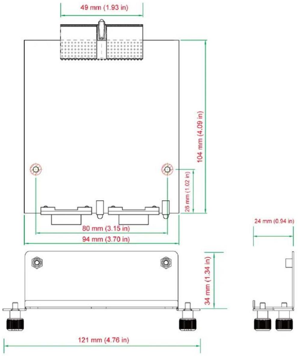
Dimensions: 104 x 121 x 34 mm (4.09 x 4.76 x 1.34 in)
Environmental Limits
Operating Temperature: -40 to 70°C (-40 to 158°F)
EPM-3112 Specifications
CANbus Communication
Interface: 2 optically isolated CAN2.0A/2.0B compliant ports
CAN Controller: Phillips SJA1000T
Signals: CAN-H, CAN-L
Isolation: 2 KV digital isolation
Speed: 1 Mbps
Connector Type: DB9 male
Physical Characteristics
Weight: 127 g
Dimensions: 104 x 121 x 34 mm (4.09 x 4.76 x 1.34 in)
Environmental Limits
Operating Temperature: -25 to 55°C (-13 to 131°F)
EPM-3337 Specifications
Cellular Interface
Frequency Bands:
• UMTS/HSDPA: Triple band, 850/1900/2100 MHz
• GSM/GPRS/EDGE: Quad band, 850/900/1800/2100 MHz
• GSM Dass: Small MS
Output Power:
• Class 4 (+33dBM ±2dB) for EGSM 850
• Class 4 (+33dB M ±2dB) for EGSM 900
• Class 1 (+30dB ±2dB) for GSM 1800
• Class 1 (+30dB ^TM ±2dB) for GSM 1900
• Class E2 (+27dBM ±3dB) for GSM 850 8-PSK
• Class E2 (+27dBM ±3dB) for GSM 900 8-PSK
• Class E2 (+26dB ^3 ± 3/-4dB) for GSM 1800 8-PSK
• Class E2 (+26dB ^3 ± 3/-4dB) for GSM 1900 8-PSK
• Class 3 (+24dB ±1/-3dB) for UMTS 2100 WCDMA FDD Bdl
- Class 3 (+24dB ^TM ±1/-3dB) for UMTS 1900 WCDMA FDD BdII
- Class 3 (+24dB ^TM ±1/-3dB) for UMTS 850 WCDMA FDD BdV
Power Supply: 3.2 to 4.2 V
HSDPA Interface
3GPP Release 5:
• 3.6 Mbps, UL 384 Kbps
• UE CAT. [1-6], 11, 12 supported
- Compressed mode (CM) supported according to 3GPP TS25.212
GPS Interface
Protocol: NMEA
Modes: GPS, assisted GPS (AGPS)
Sensitivity: At antenna connector
• Acquisition sensitivity: -143 dBm
- Tracking sensitivity: -156 dBm
General: Power saving modes, power supply for active antenna
AT Commands:
• AT-Hayes GSM 07.05 and 07.07, Cinterion
- AT commands for RIL compatibility (NDIS/RIL)
GSM/ GPRS/ EDGE Interface
GPRS:
- Multislot Class 10
• Full PBCCH support
- Mobile Station Class B
• Coding Schemes 1-4
EGPRS:
- Multislot Class 10
• EDGE E2 power class for 8 PSK
- Downlink coding schemes CS 1-4, MCS 1-9
• Uplink coding schemes CS 1-4
- BEP reporting
• SRB loopback and test mode B
- 8-bit, 11-bit RACH
- PBCCH support
• 1 phase or 2 phase access procedures
- Link adaptation and IR
• NACC, extended UL TBF
- Mobile Station Class B
CSD:
• V.110, RLP, non-transparent
• 9.6 kbps
SMS:
- Point-to-point MT and MO
- Cell broadcast
- Text and PDU mode
Fax: Group 3 Class 1
Audio:
• Audio speech codecs
• GSM: AMR, EFR, FR, HR
• 3GPP: AMR
- DTMF supported
- 6 audio modes: Approval, Router, Handset, Headset, Speakerphone, and Transparent Mode
- TTY support selecting a dedicated audio mode
- Gains and volumes can be controlled by AT commands
• 9 ringing melodies supported
- CEPT and ANSI supervisory tones supported
• Japan supervisory tones supported
WLAN
Standards:
• IEEE 802.11a/b/g/n for Wireless LAN
• IEEE 802.11i for Wireless Security
Spread Spectrum and Modulation (typical):
• DSSS with DBPSK, DQPSK, CCK
• OFDM with BPSK, QPSK, 16QAM, 64QAM
• 802.11b: CCK @ 11/5.5 Mbps, DQPSK @ 2 Mbps, DBPSK @ 11 Mbps
- 802.11a/g: 64QAM @ 54/48 Mbps, 16QAM @ 36/24 Mbps, QPSK @ 18/12 Mbps, BPSK @ 9/6 Mbps
• 802.11n: 64QAM @ 300 to BPSK @ 6.5 Mbps (multiple rates supported)
Operating Channels (central frequency):
• US: 2.412 to 2.462 GHz (11 channels), 5.18 to 5.24 GHz (4 channels)
• EU: 2.412 to 2.472 GHz (13 channels), 5.18 to 5.24 GHz (4 channels)
• USA: 1 to 11 (2400 to 2483.5 MHz)
• Europe: 1 to 13 (2400 to 2483.5 MHz)
• Japan: 1 to 14 (2400 to 2497 MHz)
802.11g:
• USA: 1 to 11 (2400 to 2483.5 MHz)
• Europe: 1 to 13 (2400 to 2483.5 MHz)
• Japan: 1 to 13 (2400 to 2497 MHz)
802.11a:
• USA: 36 to 165 (5180 to 5825 MHZ)
• Europe: 36 140 (5180 to 5700 MHz)
• Japan: 7 to 11 (5035 to 5055MHz), 183 to 189 (4915 to 4945 MHz)
Security: 64-bit and 128-bit WEP encryption, WPA /WPA2-Personal and Enterprise (IEEE 802.1X/RADIUS, TKIP and AES)
Transmission Rates:
• 802.11b: 1, 2, 5.5, 11 Mbps
• 802.11a/g: 6, 9, 12, 18, 24, 36, 48, 54 Mbps
• 802.11n: 6 to 300 Mbps (multiple rates supported)
TX Transmit Power:
• 802.11b: 1 to 11 Mbps: Typ. 18 dBm (± 1.5 dBm)
- 802.11g: 6 to 24 Mbps: Typ. 18 dBm (± 1.5 dBm); 36 to 48 Mbps: Typ. 17 dBm (± 1.5 dBm); 54 Mbps: Typ. 15 dBm (± 1.5 dBm)
- 802.11a: 6 to 24 Mbps: Typ. 17 dBm (± 1.5 dBm) 36 to 48 Mbps: Typ. 16 dBm (± 1.5 dBm); 54 Mbps: Typ. 14 dBm (± 1.5 dBm)
TX Transmit Power MIMO:
- 802.11a/n (20/40 MHz): MCS15 20 MHz: Typ. 13 dBm ( ± 1.5 dBm); MCS15 40 MHz: Typ. 12 dBm ( ± 1.5 dBm)
- 802.11g/n (20/40 MHz): MCS15 20 MHz: Typ. 14 dBm ( ± 1.5 dBm); MCS15 40 MHz: Typ. 13 dBm ( ± -1.5 dBm)
RX Sensitivity:
• 802.11b:
-92 dBm @ 1 Mbps, -90 dBm @ 2 Mbps, -88 dBm @ 5.5 Mbps, -84 dBm @ 11 Mbps
• 802.11g:
• 802.11a:
-87 dBm @ 6 Mbps, -86 dBm @ 9 Mbps, -85 dBm @ 12 Mbps, -82 dBm @ 18 Mbps,
-80 dBm @ 24 Mbps, -76 dBm @ 36 Mbps, -72 dBm @ 48 Mbps, -70 dBm @ 54 Mbps
-87 dBm @ 6 Mbps, -86 dBm @ 9 Mbps, -85 dBm @ 12 Mbps, -82 dBm @ 18 Mbps, -80 dBm @ 24 Mbps, -76 dBm @ 36 Mbps, -72 dBm @ 48 Mbps, -70 dBm @ 54 Mbps
RX Sensitivity MIMO:
• 802.11a/n:
-68 dBm @ MCS15 40 MHz, -70 dBm @ MCS7 40 MHz, -69 dBm @ MCS15 20 MHz, -71 dBm @ MCS7 20 MHz
• 802.11g/n:
-68 dBm @ MCS15 40 MHz, -70 dBm @ MCS7 40 MHz, -69 dBm @ MCS15 20 MHz,
-71 dBm @ MCS7 20 MHz
General Protocols: Proxy ARP, DNS, HTTP, HTTPS, IP, ICMP, SNTP, TCP, UDP, RADIUS, SNMP, PPPoE, DHCP
AP-only Protocols: ARP, BOOTP, DHCP, dynamic VLAN-Tags for 802.1X-Clients, STP/RSTP (IEEE 802.1D/w)
WLAN Interface
Default Antenna: 2 dBi dual-band omni-directional antenna, RP-SMA (male)
Connector for External Antennas: RP-SMA (female)
Physical Characteristics
Weight: 220 g
Dimensions: 104 x 121 x 34 mm (4.09 x 4.76 x 1.34 in)
Environmental Limits
Operating Temperature: -25 to 55°C (-13 to 131°F)
EPM-3438 Specifications
Digital Input
Input Channels: 8, source type
Input Voltage: 0 to 5 VDC at 15 Hz
Digital Input Levels:
- Logic level 0: Close to GND
- Logic level 1: Open
Connector Type: Terminal block
Digital Output
Output Channels: 8, sink type, 0 to 5 VDC
Output Current: Max. 20 mA per channel
Output Voltage:
- Logic 0: 0 to 0.55 V
- Logic 1: 4.2 to 5.0 V
Connector Type: Terminal block
Physical Characteristics
Weight: 120 g
Dimensions: 104 x 121 x 34 mm (4.09 x 4.76 x 1.34 in)
Environmental Limits
Operating Temperature: -40 to 70°C (-40 to 158°F)
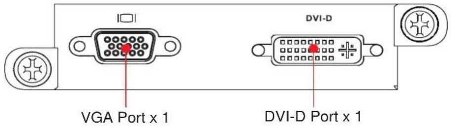
EPM-3552 Specifications
Display
Graphics Controller: DsiplayLink DL-195
VGA Interface: 15-pin D-sub connector (female)
DVI Interface: 24-pin DVI-D connector (female)
Resolution: Up to 1920x 1600 (2048 x 1152 for wide screen) resolution
Physical Characteristics
Weight: 130 g
Dimensions: 104 x 121 x 34 mm (4.09 x 4.76 x 1.34 in)
Environmental Limits
Operating Temperature: -25 to 55°C (-13 to 131°F)
The EPM Series expansion modules are designed to work with Moxa's V2422 and V2426 embedded computers. By providing different modules with different connectors, the EPM series offers the greatest flexibility and convenience for users who would like to easily establish industrial applications that require different communication interfaces.
The following topics are covered in this chapter:
□ Appearance
Dimensions
Appearance
EPM-3032
EPM-3112
EPM-3337
flowchart
graph TD
    A["Antenna Connector x 4"] --> B["WiFi"]
    A --> C["Cellular"]
    A --> D["GPS"]
    A --> E["WiFi"]
EPM-3438
EPM-3552
EPM-DK01
Dimensions
In this chapter, we show how to connect the embedded computers to the network and to various devices.
The following topics are covered in this chapter:
□ Installing the EPM Expansion Modules
□ Connecting Data Transmission Cables
Connecting to the EPM-3032 Serial Port Module
Connecting to the EPM-3337 Wireless/GPS Module
Connecting to the EPM-3438 DI/DO Module
Connecting to the EPM-3112 CANbus Port Module
Connecting to the EPM-DK01 Module
Installing the EPM Expansion Modules
The EPM series expansion modules are designed to work with Moxa's V2422 and V2426 embedded computers. Below we describe how to insert the modules into the embedded computer slots.
- Remove the module cover screws.
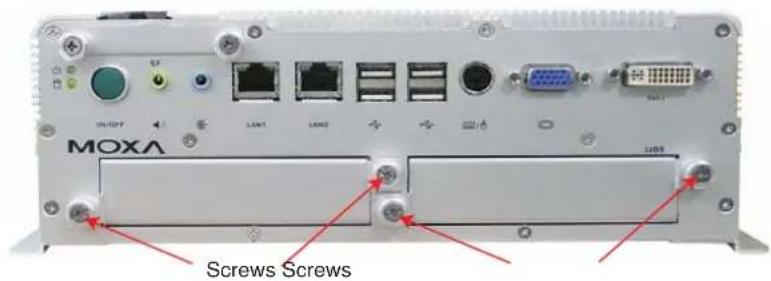
- Remove the cover from the slot.
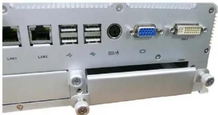
natural_image
Front view of a network device rear panel showing ports, connectors, and a central VGA (no text or symbols visible)- Gently insert the module into the slot.
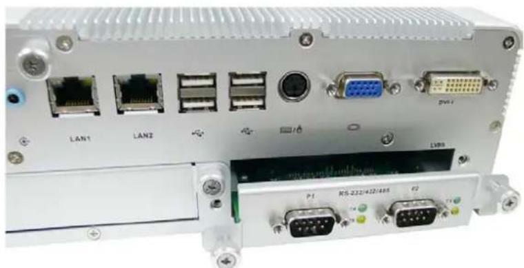
natural_image
Front view of a network equipment chassis showing ports, connectors, and I/O ports (no readable text or symbols)- When finished, tighten the screws to hold the module in place.
Connecting Data Transmission Cables
In this section we explain how to connect the EPM modules to devices.
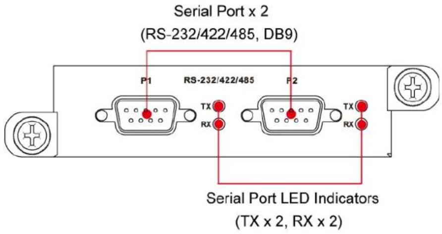
Connecting to the EPM-3032 Serial Port Module
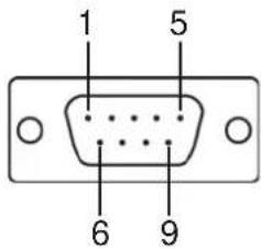
Use a serial cable to plug your serial device into the module's serial port. Serial ports 1 and 2 have male DB9 connectors and can be configured for RS-232, RS-422, or RS-485 communication by software. The pin assignments are shown in the following table:
DB9 Male Port RS-232/422/485 Pinouts
| Pin RS-232 RS-422 RS-485 | (4-wire) | RS-485 (2-wire) | ||
| 1 | DCD | TxD A(-) | TxD A(-) | - |
| 2 | RxD | TxD B(+) | TxD B(+) | - |
| 3 | TxD | RxD B(+) | RxD B(+) | DataB(+) |
| 4 | DTR | RxD A(-) | RxD A(-) | DataA(-) |
| 5 | GND | GND | GND | GND |
| 6 | DSR | - | - | - |
| 7 | RTS | - | - | - |
| 8 | CTS | - | - | - |
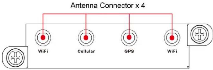
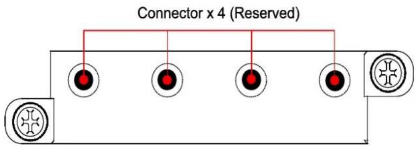
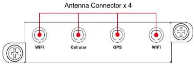
Connecting to the EPM-3337 Wireless/ GPS Module
The EPM-3337 module comes with 4 connectors that can be used to connect antennas, including 2 WiFi antennas, 1 cellular antenna, and 1 GPS antenna. Refer to the following figure for the location of the different antennas.
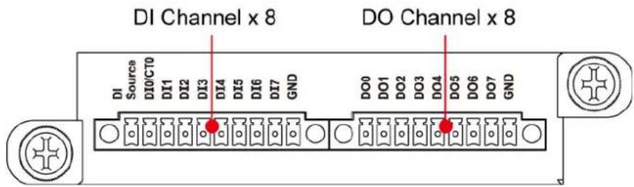
Connecting to the EPM-3438 DI / DO Module
The EPM-3438 module comes with 8 digital input channels and 8 digital output channels. See the following figures for pin definitions and wiring methods.
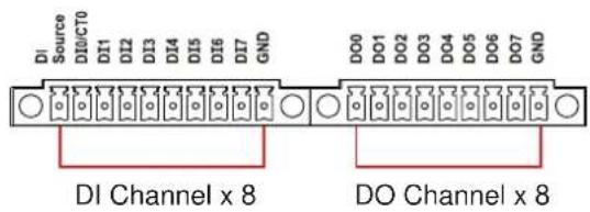
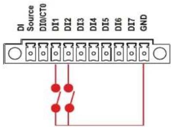
Digital Input
Dry Contact Wiring
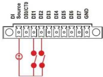
Digital Input
Wet Contact Wiring
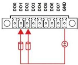
Digital Output Wiring
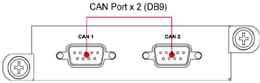
Connecting to the EPM-3112 CANbus Port Module
The EPM-3112 offers two CANbus ports with DB9 male connectors. Use a cable to plug your CAN device into the module's serial port. The pin assignments are shown in the following table:
DB9 Male CANbus Pinouts
| PIN | CAN |
| 1 | --- |
| 2 | CAN-L |
| 3 | --- |
| 4 | --- |
| 5 | --- |
| 6 | --- |
| 7 | CAN-H |
| 8 | --- |
| 9 | --- |
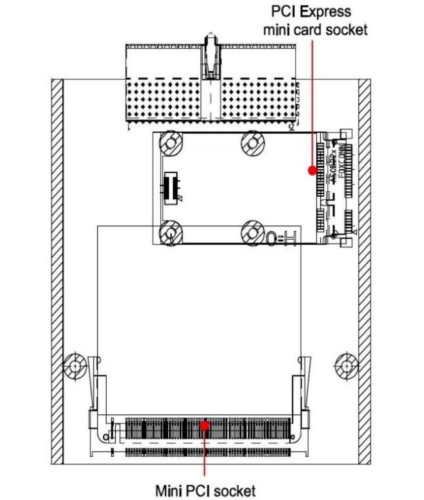
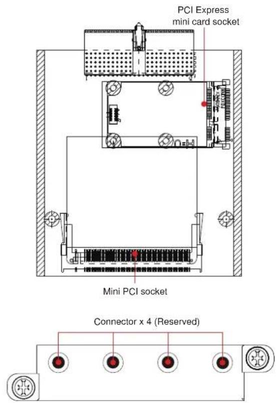
Connecting to the EPM-DK01 Module
The EPM-DK01 offers a mini-PCI and a mini-PCIe sockets, allowing users to insert a mini-PCI or a mini-PCIe card. See the following figure for the specific locations when installing these cards. Meanwhile, if you need to connect the antenna, use the connectors on the exterior panel.
Software Installation and Programming Guide
In this chapter we discuss software installation and programming guide for the EPM-3032, EPM-3337, and EPM-3438 expansion modules.
The following topics are covered in this chapter:
□ Linux System
➢ EPM-3032 Driver Installation
▶ EPM-3032 Programming Guide
➢ EPM-3438 Driver Installation
➢ EPM-3438 Programming Guide
EPM-3337 Driver Installation
➢ EPM-3112 Driver Installation
➢ EPM-3112 Programming Guide
□ Windows System
EPM-3032 Driver Installation
- Configuring Serial Port Mode
➢ Changing UART Mode Through Programming
▶ EPM-3438 Driver Installation
EPM-3438 Programming Guide
EPM-3337 Driver Installation
▶ Wireless Module Driver Installation
➢ Configuring the GPRS/HSDPA Connection (without GPS)
Enabling GPS Functionality
- Configuring a Wireless Connection
➢ Getting Wireless Module Information
EPM-3112 Driver Installation
➢ EPM-3112 Programming Guide
Linux System
EPM-3032 Driver Installation
The EPM-3032 supports Linux standard termios control. The normal tty device node is located at /dev/ttyM8, ttyM9. /dev/ttyM16 and ttyM17 are the second device files for the EPM-3032 module. The Moxa UART Device API allows you to configure ttyMx for RS-232, RS-422, 4-wire RS-485, or 2-wire RS-485.
The EPM-3032 driver has been pre-installed at the following location, and will be loaded automatically when the system boots up.
Moxa:~# /lib/modules/2.6.30-bpo.2-686/kernel/drivers/char/mxser.ko
EPM-3032 Programming Guide
Example to set the baud rate
#define MOXA 0x400
#define MOXA_SET_SPECIAL_BAUD_RATE (MOXA+100)
#define MOXA_GET_SPECIAL_BAUD_RATE (MOXA+101)
#include <termios.h>
    struct termios term;
    int fd, speed;
    fd = open("/dev/ttyM8", O_RDWR);
    tcgetattr(fd, &term);
    term.c_cflag &= ~(CBAUD | CBAUDEX);
    term.c_cflag |= B4000000;
    tcsetattr(fd, TCSANOW, &term);
    speed = 115200;
    ioctl(fd, MOXA_SET_SPECIAL_BAUD_RATE, &speed);
Example to get the baud rate
#define MOXA 0x400
#define MOXA_SET_SPECIAL_BAUD_RATE (MOXA+100)
#define MOXA_GET_SPECIAL_BAUD_RATE (MOXA+101)
#include <termios.h>
    struct termios term;
    int fd, speed;
    fd = open("/dev/ttyM8", O_RDWR);
    tcgetattr(fd, &term);
    if ((term.c_cflag & (CBAUD|CBAUDEX)) != B4000000) {
    // follow the standard termios baud rate define
    } else {
    ioctl(fd, MOXA_GET_SPECIAL_BAUD_RATE, &speed);
    }
}
Baud rate inaccuracy
Divisor = 921600/Target Baud Rate. (Only Integer part)
ENUM = 8 * (921600/Targer - Divisor) (Round up or down)
Inaccuracy = (Target Baud Rate - 921600/(Divisor + (ENUM/8))) * 100%
E.g.,
To calculate 500000 bps
Divisor = 1, ENUM = 7,
Inaccuracy = 1.7%
* For reliable performance, inaccuracy should be under 2%
Special Note
The embedded serial ports do not support special baud rates and the maximum baud rate is only 115200 bps. However, the expansion board can support special baud rates and maximum baud rates of up to 921600 bps.
If the target baud rate is not a special baud rate (e.g. 50, 75, 110, 134, 150, 200, 300, 600, 1200, 1800, 2400, 4800, 9600, 19200, 38400, 57600, 115200, 230400, 460800, 921600), the termios cflag will be set to the same flag.
If you use stty to get the serial information, you will get speed equal to 0.
Configure Serial Port Mode
Use "setinterface" command to retrieve the parameters of the serial port configuration.
Moxa:~# setinterface
Usage: setinterface device-node [interface-no]
device-node - /dev/ttyMn; n = 0,1,2,...
interface-no - following:
none - to view now setting
0 - set to RS232 interface
1 - set to RS485-2WIRES interface
2 - set to RS422 interface
3 - set to RS485-4WIRES interface
Moxa:~#
The different serial modes use specific parameters.
1 - set to RS485-2WIRES interface
2 - set to RS422 interface
3 - set to RS485-4WIRES interface
To check the current interface setting:
Moxa: ~# setinterface /dev/ttyM8
Now setting is RS485-2WIRES interface.
In this case, Serial Port 1 is set as RS-485 2-wire. (M0 refers to port 1, and M1 refers to port 2, and so on)
To change the current interface setting:
Moxa: ~# setinterface /dev/ttyM8 2
Moxa: ~# setinterface /dev/ttyM8
Now setting is RS422 interface.
In this case, Serial Port 1 has been changed and is set as RS-422 mode.
To load the settings as the Default Value:
When OS boots up, the default interface mode of the EPM-3032 is RS232. If you want to change the default interface mode, please use the following steps:
First remount the read-only root file system in writable mode.
Moxa:~# mount -o remount,rw /dev/hda1 /
Moxa:~#
Next, edit / etc/ udev/ rules.d/ 96-moxa.rules. Add the following description to 96-moxa.rules. The VendorID of the EPM-3032 must be 0x1393 and the DeviceID must be 0x1022. For example:
<h1 id="set-the-device-epm-3032-0x13930x1022-default-as-232-mode-interface">Set the device, EPM-3032, 0x1393:0x1022 default as 232 mode interface</h1>
DRIVERS=="mxser", ATTRS{vendor}=="0x1393", ATTRS{device}=="0x1022", RUN+="/bin/setinterface /dev/ttyM%n 0"
"96-moxa.rules"
Edit the command line RUN+="/ bin/ setinterface / dev/ ttyM% n 0".
If you want to set the serial mode to RS-232, use the following parameter.
RUN+ = "/ bin/ setinterface / dev/ ttyM% n 0"
If you want to set the serial mode to RS-485 2-wire, use the following parameter.
RUN+ = "/ bin/ setinterface / dev/ ttyM% n 1"
If you want to set the serial mode to RS-422, use the following parameter.
RUN+ = "/ bin/ setinterface / dev/ ttyM% n 2"
If you want to set the serial mode to RS-485 4-wire, use the following parameter.
RUN+ = "/ bin/ setinterface / dev/ ttyM% n 3"
When finished, remember to umount the writable root file system.
Moxa:~# umount /
Moxa:~#
Reboot your computer.
Moxa:~# reboot
Moxa:~#
Once the computer restarts, confirm that the setting has been loaded as the default value.
Moxa:~# setinterface /dev/ttyM8
Now setting is RS485-2WIRES interface.
Moxa:~#
EPM-3438 Driver Installation
Upload the package to embedded computer and to the tmpfs, /dev/shm.
root:~# scp epm3438-2.6.30-bpo.2-686.deb root@192.168.30.123:/dev/shm
root:~#
Install the package
Moxa:~# cd /dev/shm
Moxa:~# mount -o remount,rw /
Moxa:~# dpkg -i ./epm3438-2.6.30-bpo.2-686.de
Moxa:~# umount /
After the driver installs, you can use lsmod to check if the epm3438 module is loaded in the kernel.
Moxa:~# lsmod|more
Module Size Used by
epm3438 4620 0
...
In /etc/init.d/moxainit.sh will add the `modprobe epm3438` and `modprobe -r epm3438` lines.
Moxa:~# vi /etc/init.d/moxainit.sh
...
start)
...
modprobe moxa_device_dio device="v2400"
modprobe mxser
modprobe epm3438
...
;;
stop)
...
modprobe -r epm3438
modprobe -r moxa_swtd
modprobe -r moxa-device-dio
;;
If you need to uninstall the driver, you can use this command:
Moxa:~# mount -o remount,rw /
Moxa:~# dpkg -r epm3438
Moxa:~# umount /
EPM-3438 Programming Guide
Digital I/O
Digital input/output channels are featured in some models of Moxa embedded computers, including the UC-7408, UC-8410, IA240, IA260, W406 and EPM-3438. These channels can be accessed at run-time for control or monitoring using the functions in the following sections. Digital Output channels can be set to high or low via each port starting from 0. The Digital Input channels can be used to detect the state change of the digital input signal. The header file of digital I/O functions is mxdgio.h, which is located in the digit_input_change directory for Linux.
Moxa functions for DI/DO
| Function | HANDLE mxdgio_epm3438_open(int HWIndex); |
| Description This function opens access to the DIO device. | |
| InputThe first or second EPM-3438 board. | |
| Output | None |
| Return When successful, this function returns an access to the DIO device. Otherwise, there is an error. | |
| Function void | mxdgio_close(HANDLE fd); |
| Description This function closes the access to the DIO device. | |
| InputThe access to the device. | |
| Output | None |
| Return | None |
| Function int m | xdgio_get_input_signal(HANDLE fd, int port); |
| Description This function gets the signal state of a digital input channel. | |
| InputThe access to the device.port # | |
| OutputDIO_HIGH (1) for high, DIO_LOW (0) for low | |
| Return | Returns 1 for a high signal or 0 for a low signal, if successful. Otherwise, it returns a value of -1. |
| Function | int mxdgio_get_output_signal(HANDLE fd, int port); |
| Description This function gets the signal state of a digital output channel. | |
| InputThe access to the device.Port number | |
| Output | None |
| Return | Returns 1 for a high signal or 0 for a low signal, if successful. Otherwise, it returns a value of -1. |
| Function | int mxdgio_set_output_signal_high(HANDLE fd, int port); |
| Description This function sets a high signal to a digital output channel. | |
| InputThe access to the device.Port number. | |
| Output | none. |
| Return | When successful, this function returns 0. When an error occurs, it returns -1. |
| Function | int mxdgio_set_output_signal_low(HANDLE fd, int port); |
| Description This function sets a low signal to a digital output. | |
| InputThe access to the device.Port number. | |
| Output | none. |
| Return | When successful, this function returns 0. When an error occurs, it returns -1. |
Moxa I/O control definitions for COUNTER
define COUNTER_NODE1 "/dev/epm_3438_counter1"
define COUNTER_NODE2 "/dev/epm_3438_counter2"
| Function int mxdgio_epm3438_get_counter(int fd); | |
| Description get the counter value | |
| InputThe access to the counter device.Port number. | |
| Output | none. |
| Return | the counter value |
| Function int m | xdgio_epm3438_clear_counter(int fd); |
| Description Clear the counter value | |
| InputThe access to the counter device. | Port number. |
| Output | none. |
| Return 0:clear | success; -n: clear fail |
Special Note
- We have provided an example in CD digit_input_change. The mxdgio.h defines the convenient API for DIO and COUNTER programming.
- The DO initial status is HIGH. If you want the initial DO status to be LOW, you should add one line in /etc/modules to load epm_3438.ko with epm3438_DO2LOW=1;
Moxa: ~# modinfo /lib/modules/2.6.30-bpo.2-686/kernel/drivers/char/epm_3438.ko
filename:    /lib/modules/2.6.30-bpo.2-686/kernel/drivers/char/epm_3438.ko
description: EPM-3438: DIO/Counter module
author:    jared_wu@moxa.com
license:    GPL
depends:
vermagic:  2.6.30-bpo.2-686 SMP mod_unload modversions 686
parm:    epm3438_DO2LOW:Reset DO to LOW. 0. Set DO to High (default). 1. Set DO to LOW. (int)
Moxa: ~# mount -o remount,rw /
Moxa: ~# vi /etc/init.d/moxainit.sh
...
<h1 id="load-the-epm-3438-dio-driver">Load the EPM-3438 DIO driver.</h1>
modprobe epm_3438 epm3438_DO2LOW=1
...
Moxa: ~# umount /
This DIO sample program shows how users can develop a set of higher layer functions using preliminary DIO functions from the peripheral I/O library. These functions allow user applications to focus on event handling when events occur. A callback function is defined by the programmer to associate with an event. The source code files of the sample program are located in the samples/mxphio/digit_input_change directory for Linux Four higher layer functions, digit_io_timer_init, digit_io_timer_dispatch,
digit_io_timer_add_callback, and digit_io_timer_dispatch_quit, are provided. Four callback functions in the sample are added for four different events: DGTIO_GET_INPUT_STATE_CHANGE,
DGTIO_GET_INPUT, DGTIO_GET_OUTPUT, and DGTIO_SET_OUTPUT, via the digit_io_timer_add_callback function.
mngr = digit_io_timer_init();
...
if (digit_io_timer_add_callback(mngr, HWIndex, port, DGTIO_GET_INPUT_STATE_CHANGE, interval, input_chg_cb, &port) < 0) {
...
}
if (digit_io_timer_add_callback(mngr, HWIndex, port, DGTIO_GET_INPUT, interval, input_get_cb, &port) < 0) {
...
}
if (digit_io_timer_add_callback(mngr, HWIndex, port, DGTIO_SET_OUTPUT, interval, output_set_cb, &port) < 0) {
    ...
}
if (digit_io_timer_add_callback(mngr, HWIndex, port, DGTIO_GET_OUTPUT, interval, output_get_cb, &port) < 0) {
    ...
}
digit_io_timer_dispatch(mngr);
Examples
DIO Program Source Code File Example
File and Folder: digit_input_change/digit_io_timer.c
Description: Routines to operate timer functions on digital IO port.
#include <stdio.h>
#include <stdlib.h>
#if !defined(_WIN32_WCE) && !defined(WIN32)
#include <time.h>
#endif
#include "digit_io_timer.h"
/* callback function */
static void
dgio_input_change_exec(DGIOMNGR *mngr, DGIOITEM *item)
{
    int sig;
    HANDLE fd=mngr->fd[item->HWIndex];
    switch(item->mode)
    {
    case DGTIO_GET_INPUT:
    sig = mxdgio_get_input_signal(fd, item->port);
    item->cb(item->HWIndex, item->port, sig, item->arg);
    break;
    case DGTIO_GET_OUTPUT:
    sig = mxdgio_get_output_signal(fd, item->port);
    item->cb(item->HWIndex, item->port, sig, item->arg);
    break;
    case DGTIO_GET_INPUT_STATE_CHANGE:
    sig = mxdgio_get_input_signal(fd, item->port);
    if (item->last_signal!=sig)
    {
    item->cb(item->HWIndex, item->port, sig, item->arg);
    }
    break;
    case DGTIO_SET_OUTPUT:
    sig = item->cb(item->HWIndex, item->port, item->last_signal, item->arg);
    if (sig)
    {
    mxdgio_set_output_signal_high(fd, item->port);
    }
    else
    {
mxdgio_set_output_signal_low(fd, item->port);
}
break;
default:
    return;
}
item->last_signal = sig;
}
/* release the timer operation
*/
static void
dgio_input_change_release(DGIOMNGR *mngr)
{
    int i;
    DGIOITEM *item, *next;
    item=mngr->list;
    while(item)
    {
    next = item->next;
    free(item);
    item = next;
    }
    for (i=0; i<HW_TOTAL; i++)
    if (mngr->fd[i])
    mxdgio_close(mngr->fd[i]);
}
/* this function initializes a timer manager
Returns:
Return a pointer to the manager.
*/
DGIOMNGR*
digit_io_timer_init(void)
{
    DGIOMNGR *mngr;
    mngr = (DGIOMNGR*) calloc(1, sizeof(DGIOMNGR));
    if (mngr)
    {
    mngr->fd[0] = mxdgio_open();
#if 1 // Jared, 08-10-2010, support the second EPM-3438
    mngr->fd[1] = mxdgio_epm3438_open(0); // The first EPM-3438
    mngr->fd[2] = mxdgio_epm3438_open(1); // The second EPM-3438
#endif
    if (mngr->fd[0] < 0)
    {
    free(mngr);
    mngr = NULL;
    }
    }
    return mngr;
}
/* add a digital io timer with a selected operation mode
Inputs:
<mngr> timer manager
<HWIndex> specify which hardware device;
0: embedded DIO, 1: EPM-3438 #1, 2: EPM-3438 #2
<port> specify which DIO pin
    <mode> the operation mode on the port
    <interval> the interval (in milliseconds) between 2 calls to a user-defined function
    <cb> the user-defined callback function
    <arg> argument to the function
    Returns:
    0 on success, otherwise failure
*/
int
digit_io_timer_add_callback(DGIOMNGR *mngr, int HWIndex, int port, int mode, int interval, digit_io_cb_t cb, void *arg)
{
    DGIOITEM *item;
    item = (DGIOITEM*) calloc (1, sizeof (DGIOITEM));
    if (!item)
    return -1;
    item->next = mngr->list;
    mngr->list = item;
    item->cb = cb;
    item->arg = arg;
    item->HWIndex = HWIndex; // Jared, 08-10-2010, HWIndex to support multiple boards
    item->port = port;
    item->mode = mode;
    item->interval = interval;
    item->next_time = interval;
    // Jared, 08-10-2010, HWIndex to support multiple boards
    item->last_signal = mxdgio_get_input_signal(mngr->fd[HWIndex], port);
    return 0;
}
void
digit_io_timer_dispatch_quit(DGIOMNGR *mngr)
{
    if (mngr) mngr->dispatch = 0;
}
#define MAX_TIME 0XFFFFFFF
/* start and dispatch the timer operations
Inputs:
    <mngr> the manager
Returns:
    none
*/
void
digit_io_timer_dispatch(DGIOMNGR *mngr)
{
    DGIOITEM *item;
    unsigned int ms_sleep, n;
#if !defined(_WIN32_WCE) && !defined(WIN32)
    struct timeval to;
#endif
    mngr->dispatch = 1;
    while(mngr->list && mngr->dispatch)
    {
    for (item = mngr->list; item != NULL; item = item->next)
    {
if (mngr->now_time < item->next_time)    /* not yet */
    continue;
    n = mngr->now_time - item->next_time;
    /* over due, executable */
    item->next_time = mngr->now_time+item->interval-n; /* move to the next time */
    dgio_input_change_exec(mngr,    item);
    }
    ms_sleep = MAX_TIME;
    /* get the amount of time to sleep */
    for (item = mngr->list; item != NULL; item = item->next)
    {
    if (mngr->now_time < item->next_time)    /* not yet */
    {
    n = item->next_time - mngr->now_time;
    if (n < ms_sleep) ms_sleep = n;
    continue;
    }
    }
    if    (ms_sleep!=MAX_TIME)
    {
#if !defined(_WIN32_WCE) && !defined(WIN32)
    to.tv_sec    =    ms_sleep/1000;
    to.tv_usec   =    (ms_sleep%1000)*1000;
    if (select (0, NULL, NULL, 0, &to) != 0) /* sleep */
    break;
#else
    Sleep(ms_sleep);
#endif
    mngr->now_time    +=    ms_sleep;
    }
    }
    dgio_input_change_release(mngr);
}
File and Folder: digit_input_change/main.c
Description: This program is an example to operate timer functions on digital IO ports.
#include <stdio.h>
#include <stdlib.h>
#include "digit_io_timer.h"
static int
input_chg_cb(int HWIndex, int port, int sig, void *arg)
{
    printf("input_chg_cb() HWIndex %d port %d sig %d\n", HWIndex, port, sig);
    return 0;
}
static int
input_get_cb(int HWIndex, int port, int sig, void *arg)
{
    printf("input_get_cb() HWIndex %d port %d sig %d\n", HWIndex, port, sig);
    return 0;
}
static int
output_set_cb(int HWIndex, int port, int last_sig, void *arg)
{
printf("output_set_cb() HWIndex %d port %d last sig %d\n", HWIndex, port, last_sig);
last_sig++;
last_sig%=2;
printf("new sig=%d\n", last_sig);
return last_sig;
}
static int
output_get_cb(int HWIndex, int port, int sig, void *arg)
{
    printf("output_get_cb() HWIndex %d port %d sig %d\n", HWIndex, port, sig);
    return 0;
}
#define INTERVAL 10000
int
#if defined(_WIN32_WCE)
WINAPI
WinMain( HINSTANCE hInstance, HINSTANCE hPrevInstance, LPTSTR lpCmdLine, int nCmdShow )
#else
main(int argc, char *argv[])
#endif
{
    DGIOMNGR *mngr;
    int HWIndex;
    int port;
    int interval;
#if defined(_WIN32_WCE)
    int argc;
    char cmdline[256], *argv[32];
    WideCharToMultiByte(CP_ACP, 0, (LPCTSTR)lpCmdLine, 255, cmdline, 256, NULL, NULL);
    argc = split_line(argv+1, 32, cmdline)+1;
#endif
    if (argc > 1) interval = atoi(argv[1]);
    else interval = INTERVAL;
    mngr = digit_io_timer_init();
    if (mngr == NULL) {
    printf("digit_io_timer_init() error\n");
    return -1;
    }
    HWIndex=0; // HWIndex=0 for embedded DIO
    for (port = 0; port < 1; port++) {
    if (digit_io_timer_add_callback(mngr, HWIndex, port, DGTIO_GET_INPUT_STATE_CHANGE, interval, input_chg_cb, &port) < 0) {
    printf("add %d input change callback error\n", port);
    return -2;
    }
    if (digit_io_timer_add_callback(mngr, HWIndex, port, DGTIO_GET_INPUT, interval, input_get_cb, &port) < 0) {
    printf("add %d input callback error\n", port);
    return -3;
    }
    if (digit_io_timer_add_callback(mngr, HWIndex, port, DGTIO_SET_OUTPUT, interval, output_set_cb, &port) < 0) {
c
    printf("add %d set output callback error\n", port);
    return -4;
}

if (digit_io_timer_add_callback(mngr, HWIndex, port, DGTIO_GET_OUTPUT, interval, output_get_cb, &port) < 0) {
    printf("add %d get output callback error\n", port);
    return -5;
}

// HWIndex=1 for EPM-3438 board #1; HWIndex=2, for EPM-3438 board #2
for (HWIndex = 0; HWIndex < HW_TOTAL; HWIndex++) {
    for (port = 0; port < 8; port++) {
    /* since list is LIFO last callbacks are added first */
    if (digit_io_timer_add_callback(mngr, HWIndex, port, DGTIO_GET_INPUT_STATE_CHANGE, interval, input_chg_cb, &port) < 0) {
    printf("add %d input change callback error\n", port);
    return -2;
    }
    if (digit_io_timer_add_callback(mngr, HWIndex, port, DGTIO_GET_INPUT, interval, input_get_cb, &port) < 0) {
    printf("add %d input callback error\n", port);
    return -3;
    }
    if (digit_io_timer_add_callback(mngr, HWIndex, port, DGTIO_SET_OUTPUT, interval, output_set_cb, &port) < 0) {
    printf("add %d set output callback error\n", port);
    return -4;
    }
    if (digit_io_timer_add_callback(mngr, HWIndex, port, DGTIO_GET_OUTPUT, interval, output_get_cb, &port) < 0) {
    printf("add %d get output callback error\n", port);
    return -5;
    }
    }
    digit_io_timer_dispatch(mngr);
    return 0;
}

Examples
Counter Program Source Code File Example
File and Folder: digit_input_change/tcounter.c
Description: This file is an example of the EPM-3438 couter programming.
read the counter value.
read the counter value and clear the counter.
#include <stdio.h>
#include <stdlib.h>
#include <sys/time.h>
#include <fcntl.h>
#include <unistd.h>
#include <signal.h>
#include "mxdgio.h" // For counter reading or clear
#define COUNTER_NODE1 "/dev/epm_3438_counter1" // The first EPM-3438
#define COUNTER_NODE2 "/dev/epm_3438_counter2" // The second EPM-3438
int main(int argc, char * argv[])
{
int retval;
int fd, fd2, len;
unsigned int counter_value;
fd=open(COUNTER_NODE1, O_RDONLY);
while(1) {
    printf("\nSelect a number of menu, other key to exit. \n\
1. Get counter value    \n\
2. Clear the counter    \n\
Others. quit    \n\
Choose : ");
    scanf("%d", &retval);
    if (retval == 1) {    // Get counter without reset
    counter_value = mxdgio_epm3438_get_counter(fd);
    printf("EPM-3438 board #1 counter:%d\n", counter_value);
    }
    else if (retval == 2) { // Get counter with reset
    retval = mxdgio_epm3438_clear_counter(fd);
    if (retval < 0)
    printf("EPM-3438 board #1 counter reset fail\n");
    }
    else {
    break;
    }
}
close(fd);
return 0;
EPM-3337 Driver Installation
Moxa's EPM-3337 module supports both 3G/GPS and wireless functionality. This section introduces how to configure these functions in the Linux platform.
- Make root file system writable
Moxa:~# mount -o remount,rw /
- Install the file epm3337.deb
Moxa:/home# dpkg -i epm3337.deb
- Setup 3G module to Mdm mode
EPM-3337's 3G module supports multiple modes, issue lsusb to get information:
• 0681:0040 - MdmNet mode (the default factory setting)
• 0681:0047 - Mdm mode (for Linux)
Now convert EPM-3337 module with the moxa_hc25_setup_mdm.sh script at / home
Moxa:/home# sh moxa_hc25_setup_mdm.sh
Confirm that the conversion is completed
Moxa:/home# lsusb
Bus 001 Device 010: ID 0681:0047 Siemens Information and Communicat
Note: You only need to do this conversion once.
- Configure the driver to load at startup
The default run-level is 2 (setup in /etc/inittab). Issue the following command
Moxa:/etc/rc2.d# mv N98moxa hc25 load driver
Note: You need to reboot to load the driver or issue /etc/init.d/moxa_hc25_load_driver
- Install software from internet for wireless functionality
Moxa:/home# apt-get install wpasupplicant wireless-tools
- Create the correct links for wpa_supplicant
Moxa:/etc/network/if-up.d# ln -sf /etc/wpa_supplicant/ifupdown.sh
wpasupplicant
Moxa:/etc/network/if-down.d# ln -sf /etc/wpa_supplicant/ifupdown.sh
wpasupplicant
Moxa:/etc/network/if-pre-up.d# ln -sf /etc/wpa_supplicant/ifupdown.sh
wpasupplicant
Moxa:/etc/network/if-post-down.d#ln -sf
/etc/wpa_supplicant/ifupdown.sh wpasupplicant
- Mount root file system (/) as read-only
Moxa:~# umount /
- Reboot your device to complete installation

ATTENTION
ppp 2.4.4 may get the incorrect DNS after connection; here are two workaround solutions:
- Assign the DNS manually
Comment the option "usepeerdns" in /dev/pppt/chtgprs. Then assign a DNS /etc/resolv.conf manually.
#usepeerdns # use the DNS servers from the remote network
- Remove ppp 2.4.4 and install ppp-2.4.5.deb
Moxa:~# apt-get remove ppp
Moxa:/home# dpkg -i ppp-2.4.5.deb
The EPM-3337's Two Operating Modes
The EPM-3337 module has two modes:
- Normal Mode: Supports only GPRS/HSDPA functionality (without GPS).
The allocation of ports is:
• Modem port: /dev/ttyACM0
• Command port: /dev/ttyUSB0
- Multiplexer Mode: Supports both GPRS/HSDPA and GPS functionality.
It needs to perform a multiplexer program to put the module into multiplexer mode.
The allocation of ports is:
- Modem port: /dev/pts/0
• Command port: /dev/pts/1
• GPS port: /dev/pts/2
Note: If you do not need the GPS functionality, use normal mode for better performance.
Normal mode—GPRS/ HSDPA functionality only
This section illustrates how to establish a connection with pppd configuration.
The example files used are listed below:
• /etc/ppp/peers/chtgprs: a pppd additional option file
• /etc/chatscripts/chtgprs-connect - chat file for connection
• /etc/chatscripts/chtgprs-disconnect - chat file for disconnection
Follow the steps below to set up your pppd:
- Configure the /etc/ppp/ peers/chtgprs file
a. First, check if the name of the modem port is correct. It should be /dev/ ttyACM0 for the first modules, /dev/ ttyACM1 for the second one, and so on.
b. Then make sure "local" option is enabled. This option ignores the CD (Carries Detect) signal.
- Configure / etc/ chatscripts/ chtgprs-connect
a. First, check the packet data protocol type and Access point name of ISP a basic command is AT+CGDCONT=1,"
b. Then check the ATD dial out number a basic command is ATD
- Read configuration file to connect
a. pppd call chtgprs
- Finally, examine connection state.
a. If connection is ok, a device ppp0 (or pppn) is established. Issue "ifconfig ppp0" to view its information.
Multiplexer mode—GPS and GPRS/ HSDPA dual functionality
GPS functionality is only enabled in the module's multiplexer mode. In multiplexer mode, the system uses pseudo terminal slave (pts) instead of reading serial ports (/dev/ttyACMx) to communicate.
This section describes how to set up GPS functionality, work with the gpsd daemon, and change the pppd configuration file for the modem port /dev/pts/0.
The following steps illustrate how to set up GPS and use gpsd:
- Set the module to multiplexer mode at startup
Moxa:/etc/rc2.d# mv N99moxa_hc25_mux_script S99moxa_hc25_mux_script
Note: If you insert two EPM-3337 modules, you can set module_num=2 in /etc/init.d/moxa_hc25_mux_script
-
Reboot the embedded computer
-
Now the multiplexer will automatically start at bootup. It takes a modem port /dev/ttyACM0, as a parameter and create three pseudo terminal slaves
Moxa:~# ls /dev/pts/
0 1 2 ptmx
/ dev/ pts/ 0: Modem port
/ dev/ pts/ 1: Command port
/ dev/ pts/ 2: GPS port
NOTE
-
The command port in multiplexer mode only accepts AT commands with the suffix \r\n (i.e. carriage return and new line). You can see the echo example in "Enable GPS port by issuing command," or set the terminal output flag with command "stty -F / dev/ pts/ 1 opost onlcr". Here option onlcr translates newline to carriage return-newline.
-
For the second EPM3337 module, the allocation will be / dev/ pts/ 3: Modem port / dev/ pts/ 4: Command port / dev/ pts/ 5: GPS port

ATTENTION
The number assigned to pts is affected by remote log in programs (eg. ssh or telnet). Therefore, it is advisable to perform moxa_hc25_mux at startup to make sure the pts number is 0 to 2. If there is more than 1 EMP3337 module, the number of pts increases to 3 to 5 and so on.
- Enable GPS port by issuing a command to the command port
Moxa:~# cat < /dev/pts/1 &
Moxa:~# echo -e "AT^SGPSS=4\r"> /dev/pts/1
Moxa:~# killall cat
Check for NMEA data from the GPS port (/dev/pts/2)
Moxa:~# cat < /dev/pts/2 GPGSV,1,1,04,24,28,123,37,21,09,054,31,19,52,213,,23,47,270,74 GPGGA,061824.0,2458.835139,N,12133.055835,E,1,05,19.7,-103.5,M,,,14 GPRMC,061824.0,A,2458.835139,N,12133.055835,E,,,290710,,,A68 GPGSA,A,3,24,21,06,31,16,,,,,,25.5,19.7,18.529 GPVTG,,T,,M,0.0,N,0.0,K*4E
- Start gpsd and perform client program cgps Install gpsd:
Moxa:~# apt-get install gpsd
Let gpsd read NMEA data from GPS port (/dev/pts/2)
Moxa:~# gpsd /dev/pts/2
In the remote computer, use ssh connect to Moxa's embedded computer and issue the cgps command. You will see the information below
Moxa:~# cgps
If cgps gets non-null data form gpsd, it will display the message below:
| Time: 2010-07-29T06:46:38.02 Latitude: 24.980836 N Longitude: 121.552724 E Altitude: 107.5 M Speed: n/a Heading: n/a Climb: 0.0 M/Min Status: 3D FIX (13 secs) GPS Type: Generic NMEA Horizontal Err: +/- 131 M Vertical Err: +/- 78 M Course Err: n/a Speed Err: +/- 973 kph | PRN: Elev: Azim: SNR: Used: 11 04 201 00 N 7 11 319 00 N 13 37 288 13 N 24 35 108 43 Y 21 05 045 27 N 19 65 227 00 N 3 75 350 25 Y 23 44 250 00 N 6 61 026 38 Y 31 18 127 25 Y 16 37 042 40 Y |
| 0.000 0.000 ? 310.40 ? 3 GPSD, O=RMC 1280385997.000 0.005 24.980836 121.552725 107.50 139.20 83.20 0.0000 0.000 0.000 ? 288.00 ? 3 | |
NOTE You can issue AT^ SGPSS=0 to the command port to stop GPS information.
Moxa:~# cat < /dev/pts/1 &
Moxa:~# echo -e "AT^SGPSS=0\r"> /dev/pts/1
Moxa:~# killall cat

ATTENTION
View the following reference for more information about gpsd.
man gpsd
man cgps
http://gpsd.berlios.de/
As described in this section, in multiplex mode the modem port is dev/pts/0 instead of /dev/ttyACM0.
Check that the modem port is /dev/ pts/ 0 at /etc/ppp/peers/chtgprs.
<h1 id="see-etcpppoption-for-detail">See /etc/ppp/option for detail</h1>
/dev/pts/0 # modem port used
115200 # speed
Then you can connect GPRS/HSDPA through pppd
Moxa:~# pppd call chtgprs
Troubleshooting for pppd
To enable debug messages in pppd, do following steps in /etc/ppp/peers/chtgprs temporarily
- Enable option "debug" and "logfile /var/ppp.log"
- Add -V option in /usr/sbin/chat
#Debug option---
#You call tail -f /var/ppp.log &
debug
logfile /var/ppp.log
connect "/usr/sbin/chat -v -V -f /etc/chatscripts/chtgprs-connect"
Then see /var/ppp.log for more detail message.
Setting up a Wireless Connection
This section introduces how to connect to a access point with WEP/WPA/WPA2(RSN) encryption. The connection program is wpa_supplicant.
The basic command is wpa_supplicant -i
- Example 1: Connect to AP (SSID: test_wep) with WEP key 1234567890(hex)
a. Write a configure file test_wep.conf as below
network={
    ssid="test_wep"
    key_mgmt=NONE
    wep_key0=1234567890
    wep_key1="abcde"
    wep_key2="1234567890123"
    wep_tx_keyidx=0
    priority=5
}
b. Connection with following commands
wpa_supplicant -i wlan0 -c test_wep.conf -B
c. Use iwconfig to check connection state
wlan0 IEEE 802.11abgn ESSID:"test_wep"
Mode:Managed Frequency:2.462 GHz Access Point:
00:1F:1F:8C:0F:64
Bit Rate=36 Mb/s Tx-Power=27 dBm
Retry min limit:7 RTS thr:off Fragment thr:off
Encryption key:1234-5678-90 Security mode:open
Power Management:off
Link Quality=37/70 Signal level=-73 dBm
Rx invalid nwid:0 Rx invalid crypt:0 Rx invalid frag:0
Tx excessive retries:0 Invalid misc:0 Missed beacon:0
- Example 2: Connect to AP (SSID: test_wpa) with WPA key "1234567890" (ascii)
a. Write a configuration file test_wpa_wpa2.conf as below
network={
    ssid="test_wpa"
    key_mgmt=WPA-PSK
    proto=WPA RSN
    pairwise=TKIP CCMP
    group=TKIP CCMP
    psk="1234567890"
}
b. Connection with the following commands
wpa_supplicant -i wlan0 -c test_wpa_wpa2.conf -B
c. Use iwconfig to check the connection state
wlan0 IEEE 802.11abgn ESSID:"test_wpa"
Mode:Managed Frequency:2.462 GHz Access Point:
00:1F:1F:8C:0F:64
Bit Rate=36 Mb/s Tx-Power=27 dBm
Retry min limit:7 RTS thr:off Fragment thr:off
Encryption
key:157A-1DBD-B0C3-7CC8-0F9C-D059-2881-F815-E4DB-3705-6969-8253-865E-4DF0-FDB8-AEC1 [2] Security mode:open
Power Management:off
Link Quality=34/70 Signal level=-76 dBm
Rx invalid nwid:0 Rx invalid crypt:0 Rx invalid frag:0
Tx excessive retries:0 Invalid misc:0 Missed beacon:0
- Example 3: Connect to AP (SSID: test_wpa2) with WPA2 key "1234567890" (ascii)
a. The configuration file test_wpa_wpa2.conf can also apply to the WPA2 connection. By following the directions in example 2, you can get results below
wlan0 IEEE 802.11abgn ESSID:"test_wpa2"
Mode:Managed Frequency:2.462 GHz Access Point:
00:1F:1F:8C:0F:64
Bit Rate=1 Mb/s Tx-Power=27 dBm
Retry min limit:7 RTS thr:off Fragment thr:off
Encryption key:8546-8201-6DCA-8A37-6EE6-AD44-8D3F-6553 [2]
Security mode:open
Power Management:off
Link Quality=40/70 Signal level=-70 dBm
Rx invalid nwid:0 Rx invalid crypt:0 Rx invalid frag:0
Tx excessive retries:0 Invalid misc:0 Missed beacon:0

ATTENTION
View the following references for more information about wpa_supplicant.
Website: http://hostap.epitest.fi/wpa_supplicant/
The configuration README:
http://hostap.epitest.fi/gitweb/gitweb.cgi?p=hostap.git;a=blob_plain;f=wpa_supplicant/README
Getting Wireless Card Information
The program iw is a new nl80211 based CLI configuration utility. It can get more complete information than iwconfig for 802.11n. Although still under development, it contains some useful functionality.
To get the connection data, you can issue "iw dev
Moxa:~# iw dev wlan0 station dump
Station 00:1f:1f:8c:0f:64 (on wlan1)
inactive time: 35696 ms
rx bytes: 98054
rx packets: 364
tx bytes: 733
tx packets: 7
signal: -75 dBm
tx bitrate: MCS 42 40MHz

ATTENTION
View the following reference for more information about iw.
http://linuxwireless.org/en/users/Documentation/iw
EPM-3112 Driver Installation
CAN is a broadcast serial bus standard for connecting electronic control units (ECUs). Each node is able to send and receive messages, but not simultaneously: a message (consisting primarily of an ID—usually chosen to identify the message-type/sender—and up to eight message bytes) is transmitted serially onto the bus, one bit after another. This signal-pattern codes the message (in NRZ) and is sensed by all nodes.
Moxa EPM-3112 module provides the CAN bus interface for industrial CAN communication. Users can use the library or file control interface (ioctl) to read, write or control the CAN interface as a file for easy CAN programming.
Installation
- Make root file system writable
Moxa:~# mount -o remount,rw/
- Install the file epm3112.deb
Moxa:/home# dpkg -i epm3112.deb
- Mount root file system read-only
Moxa:~# umount /
- Then modprobe moxa_can or reboot your device to finish this installation
EPM-3112 Programming Guide
CANBUS Library
A simple library mxcanus_lx.c is offered; see the following sub-sections for details:
Moxa functions for CANbus
| Function | unsigned int mxcan_get_bus_timing (unsigned int fd) |
| Description Get the bus timing of an opened port. | |
| Inputthe opened port | |
| Output | None |
| Return 0 on failure, otherwise the bus speed in KHz | |
Function
int mxcan_get_parameters (unsigned int fd, CANPRM * param)
Description Get the parameter of an opened port.
Input
Output pointer to a structure of CANPRM
Return 0 on success. Otherwise return a negative value
Function int mxcan_get_registers (unsigned int fd, unsigned char * buffer, int num)
Description Get the register values of an opened port.
Input
must be 32
Output
Return 0 on success, otherwise failure
Function int mxcan_get_stat (unsigned int fd, CANBST * stat)
Description Get the statistics of an opened port.
Input
Output
Return 0 on success, otherwise failure
Function int mxcan_inqueue (unsigned int fd)
Description Get the number of received bytes that are queued in the driver of an opened port.
Input
Output None
Return < 0 on failure, the number of bytes
Function unsigned int mxcan_open (int port)
Description Open a can port by the port number
Input
Output None
Return 0 on failure, otherwise return fd
Function int mxcan_outqueue (unsigned int fd)
Description Get the number of bytes waiting for being transmitted to a can port.
Input
Output None
Return < 0 on failure, the number of bytes
Function int mxcan_purge_buffer (unsigned int fd, unsigned int purge)
Description Purge the buffers of an opened port.
Input
Output None
Return 0 on success, otherwise failure
Function int mxcan_set_bus_timing (unsigned int fd, unsigned int speed)
Description Set the bus timing of an opened port.
Input
5/10/20/40/50/80/100/125/200/250/400/500/666/800/1000
Output None
Return 0 on success, otherwise returns a negative value
Function int mxcan_set_nonblocking (unsigned int fd)
Description Set the opened fd to be non-blocking.
Input
Output None
Return 0 on success, otherwise returns a negative value
Function int mxcan_set_parameters (unsigned int fd, CANPRM *param)
Description Set the parameter of an opened port.
Input
<param> pointer to a structure of CANPRM
Output
None
Return 0 on success, otherwise return a negative value
Moxa definitions for CANbus
define mxcan_close(fd) close((int)fd)
define mxcan_read(fd, buffer, size, hndl) read((int)fd, buffer, size)
define mxcan_write(fd, buffer, size, hndl) write((int)fd, buffer, size)
Example Code
You can download the library / example code from MOXA website.
http://www.moxa.com/support/support_home.aspx

ATTENTION
View the following reference for more information
http://en.wikipedia.org/wiki/Controller_area_network
Windows System
EPM-3032 Driver Installation
Before using the EPM-3032 expansion module, you need to update the driver. Please install the driver before inserting the expansion module.
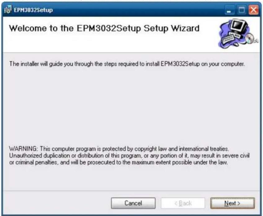
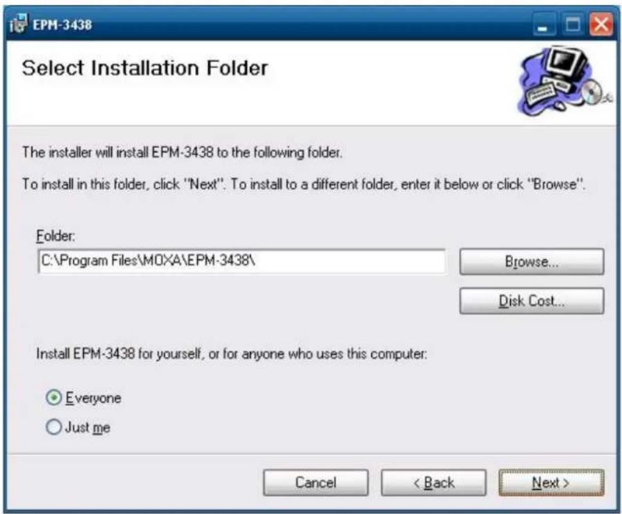
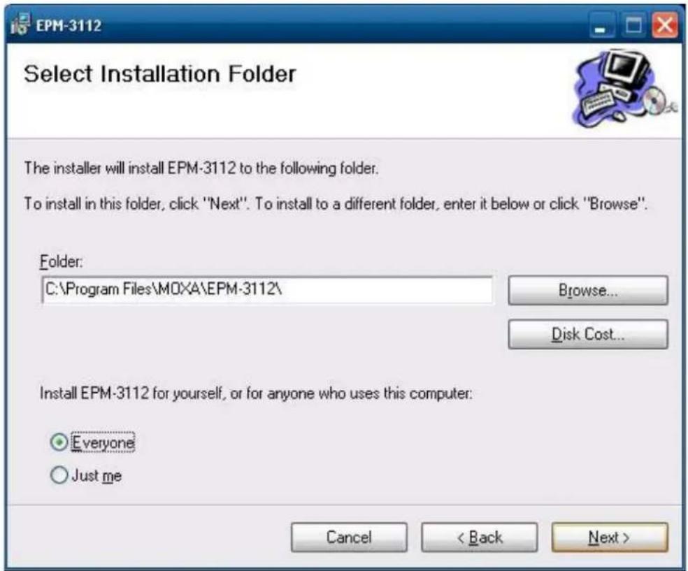
Use the following steps to install the EPM-3032 module driver
- Execute EPM3032Setup.exe to install the driver and then click "Next"
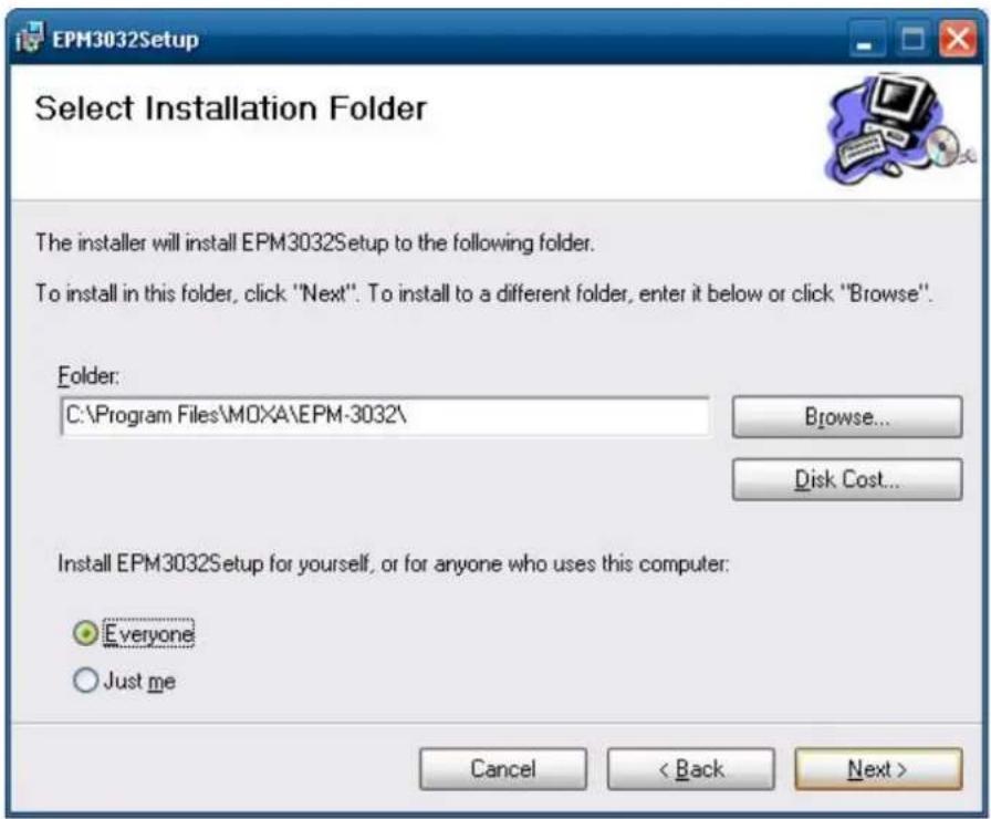
- Click Next to install using default settings.
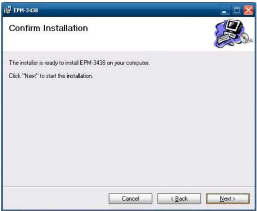
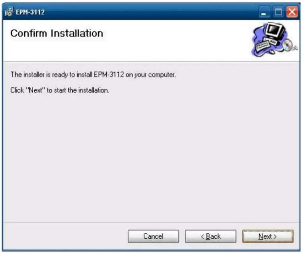
- Click Next to start the installation.

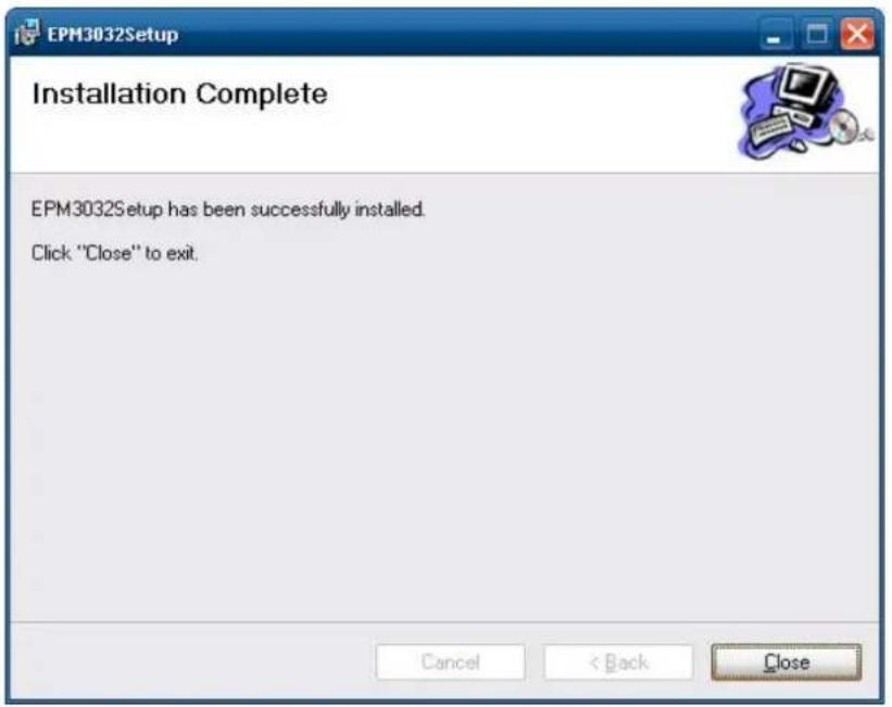
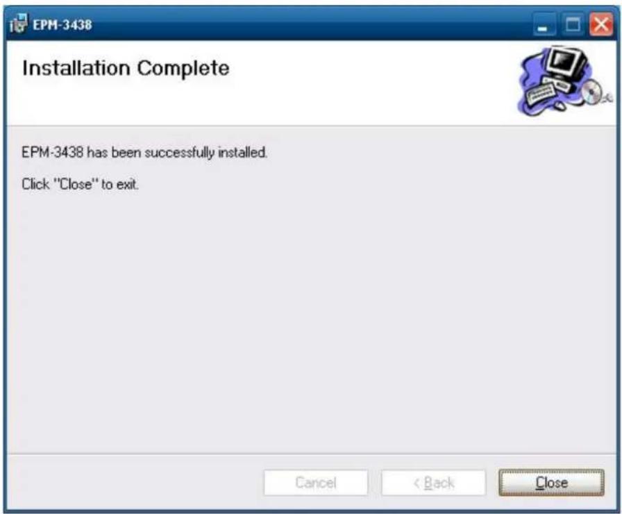
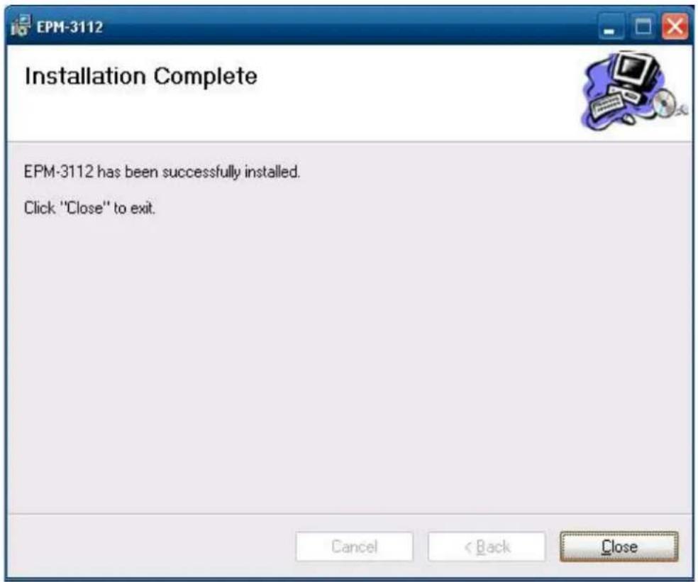
- Click Close to complete the installation.
- Now you need to shutdown the computer and insert the EPM-3032 expansion module into the embedded computer and then reboot the computer.
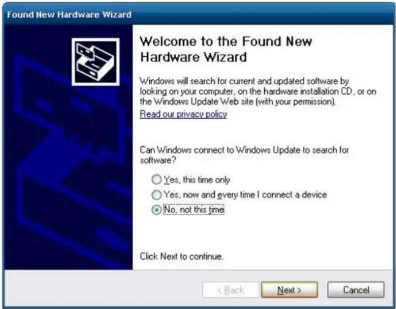
- The system will find the new hardware, select No, not this time and click Next.
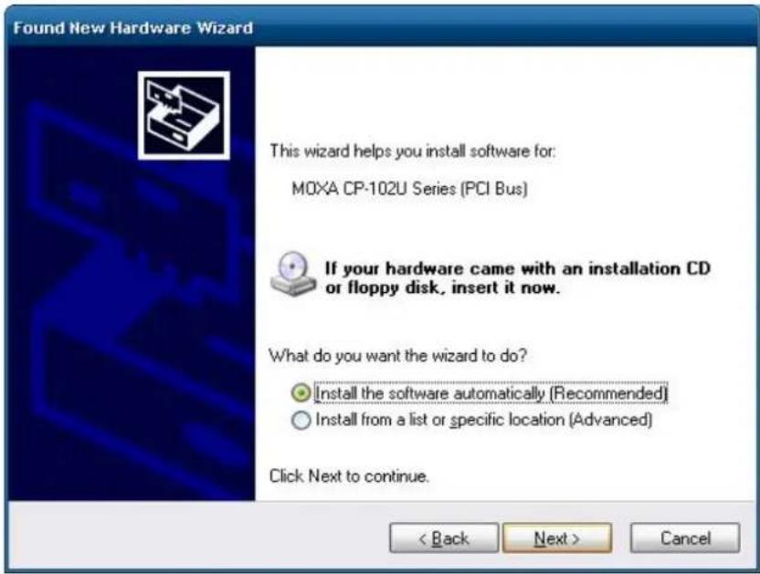
- Select Install the software automatically and then click Next.
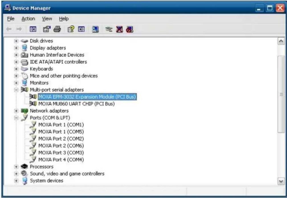
- The driver will be installed automatically. When finished, you can find the module listed in the Device Manager. You can start using the module now.
Configuring Serial Port Mode
Do the following steps to configure the operation mode of each COM port:
- Go to the Control Panel->Ports (COM & LPT) and select the COM port (ex. MOXA Port 0 (COM1)).
- Right-click the COM port and click Properties.
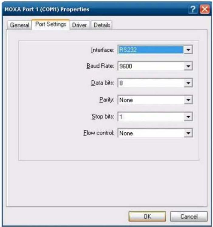
- In the Port Settings tab, select the interface you want to use.
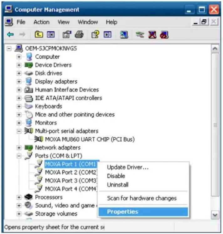
- Click OK to apply the settings.
In some situations, you may want to change the port name to fit your program. Use the following steps to change port names:
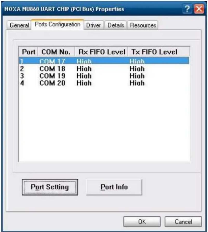
- Go to the Control Panel->Multi-port serial adapters and select the adapter
- Right-click the adapter and click Properties.
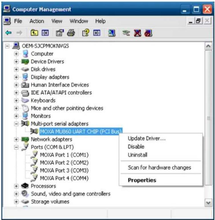
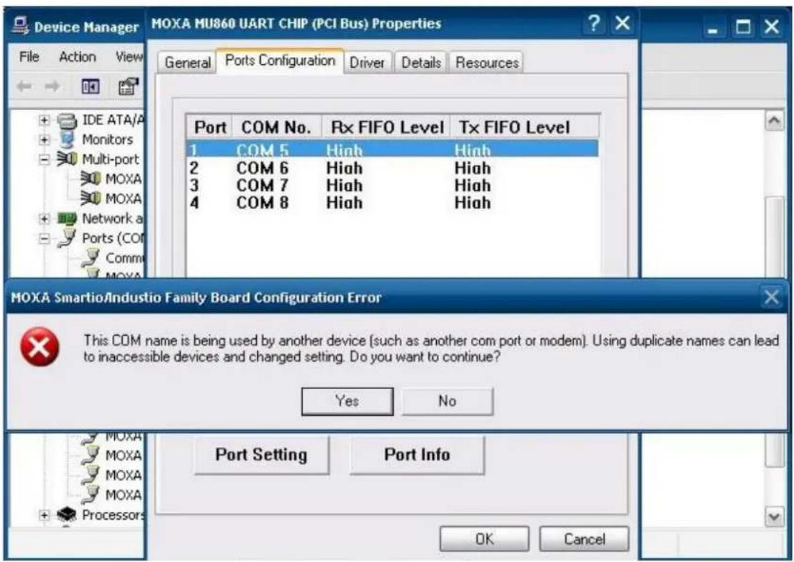
- At the Port Configuration tab, select the port and then click Port Setting.
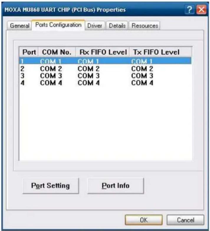
- Uncheck Auto Enumerating COM Number if you want to change the port name separately.
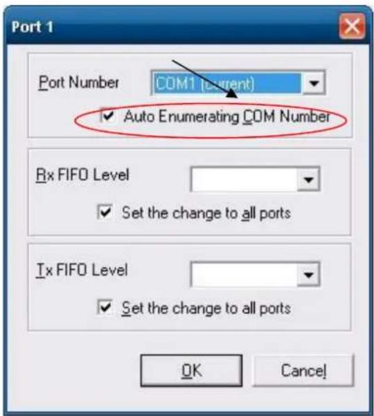
- Select the port name you want to change to, and then press OK.
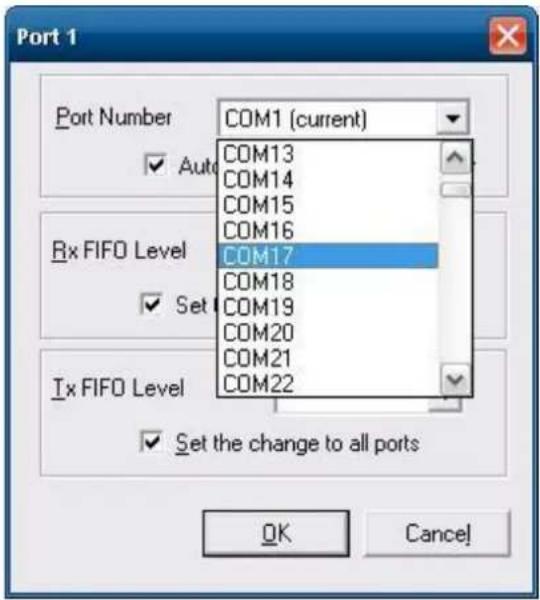
- Make sure the port names are correct, and then click OK to take effect.
- Now, you can verify that the port names have been changed under Ports (COM & LPT)
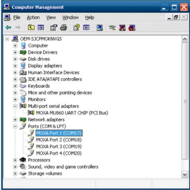
NOTE Make sure each port name is unique; duplicate names will lead to inaccessible devices
Changing UART Mode Through Programming
You can set the operation mode through programming, the example "UartMode" is under \examples\C++\ in the Software DVD.
The code snippet is as follows:
int port=0,mode=0;
    int n=0;
    WCHAR sin;
    WCHAR wcs_port[3],wcs_mode[3];
    printf("UART Mode Test Program\n");
    printf("\t (0) Exit Program\n");
    printf("\t (1) Display UART Mode\n");
    printf("\t (2) Set UART Mode\n");
    sin=getwchar();
    n=_wtoi(&sin);

    do
    {
    switch (n)
    {
    // if char == '1', display the UART Mode case 1:
    printf("Input the Port Number (5~8) = \n");
    wscanf(L"%s",wcs_port);
    port=_wtoi(wcs_port);
    mode=uart_getmode(port);
    }
    }
}
if (mode==-(-1))
{
    printf("Invalid value!!\n");
    break;
}
printf("COM%d=%s\n", port, mode_array[mode]);

break;
// if char == '2', Set the UART Mode
case 2:

// Get Port Number
printf("Input the Port Number (5~8) = \n");
wscanf(L"%s", wcs_port);
port=_wtoi(wcs_port);

// Get Mode Value
printf("Input the Mode value (0 ~ 3) = ");
wscanf(L"%s", wcs_mode);
mode=_wtoi(wcs_mode);

// Set UART Mode
if (uart_setmode(port, mode)==-1)
{
    printf("Invalid value!!\n");
    printf("Set UART Mode Fail!!\n");
}
else
{
    printf("COM%d=%s\n", port, mode_array[mode]);
}
break;
}

getwchar();
sin = getwchar();
n = _wtoi(&sin);
} while (n != 0);
return 0;
EPM-3438 Driver Installation
Before installing the EPM-3438, please select the counter mode or DI mode for the module.
There is a dip switch on the EPM-3438. If DIP switch 1 is on, the DI0 will work in digital input port mode. DI0 just reflects whether the input signal status is HIGH or LOW. If DIP switch 2 is on, the DI0 works as a 16 bit counter. It increases the counter when the input pulse is toggled from low to high. See the following figures for DIP switch settings.
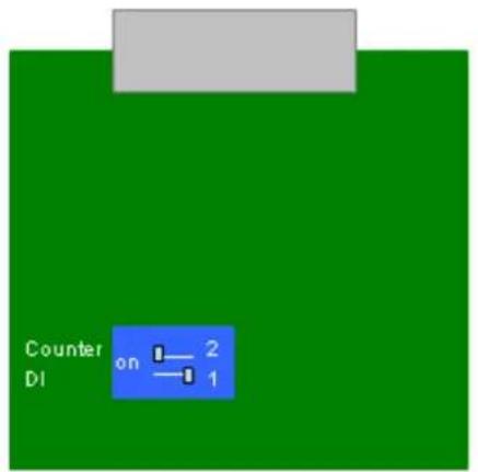
Counter mode
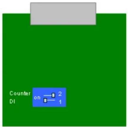
DI mode
Before using the EPM-3438 expansion module, you need to update the driver. Please install the driver before inserting the expansion module.
Use the following steps to install the EPM-3438 module driver
- Run EPM3438Setup.exe to begin installation and then click Next.
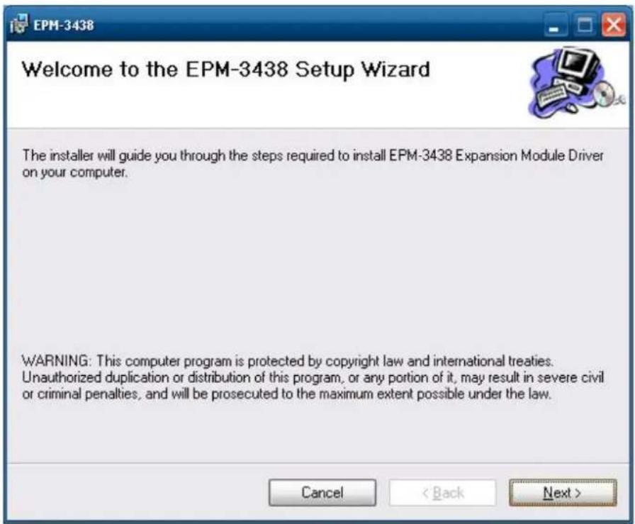
- Click Next to install by default settings.
- Click Next to begin installation.
- Click Close to complete the installation.
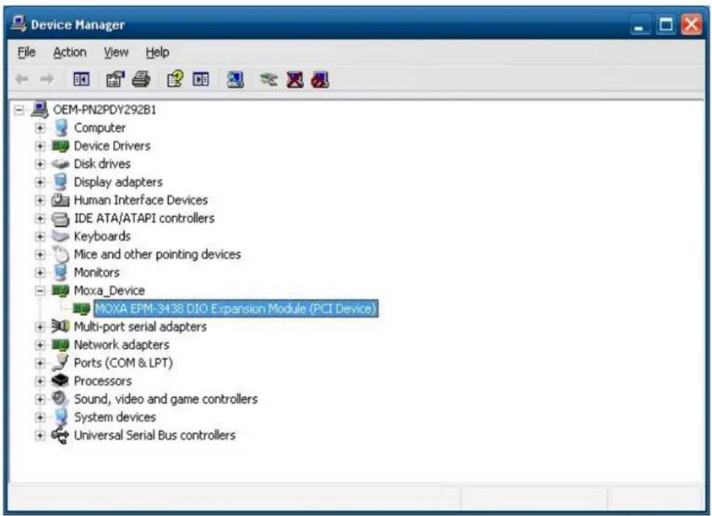
- Now you need to shut down the computer, insert the EPM-3438 expansion module into the embedded computer, and then reboot the computer.
- The system will find the new hardware and install the driver automatically; now the module is ready for use.
EPM-3438 Programming Guide
You can set operations through programming; the following "DIO" example can be found in the software DVD at \examples\C++.
Moxa functions for DI/DO
| Function HANDLE mxdgio_epm3438_open(int HWIndex); | |
| Description This function opens access to the DIO device. | |
| InputThe first or second EPM-3438 board. | |
| Output | None |
| Return | When successful, this function returns an access to the DIO device. Otherwise, there is an error. |
| Function void | mxdgio_close(HANDLE fd); |
| Description This function closes the access to the DIO device. | |
| InputThe access to the device. | |
| Output | None |
| Return | None |
| Function int m | xdgio_get_input_signal(HANDLE fd, int port); |
| Description This function gets the signal state of a digital input channel. | |
| InputThe access to the device.port # | |
| OutputDIO_HIGH (1) for high, DIO_LOW (0) for low | |
| Return | Returns 1 for a high signal or 0 for a low signal, if successful. Otherwise, it returns a value of -1. |
| Function | int mxdgio_get_output_signal(HANDLE fd, int port); |
| Description This function gets the signal state of a digital output channel. | |
| InputThe access to the device.<port> Port number | |
| Output | None |
| Return | Returns 1 for a high signal or 0 for a low signal, if successful. Otherwise, it returns a value of -1. |
| Function | int mxdgio_set_output_signal_high(HANDLE fd, int port); |
| Description This function sets a high signal to a digital output channel. | |
| InputThe access to the device.Port number. | |
| Output | none. |
| Return | When successful, this function returns 0. When an error occurs, it returns -1. |
| Function | int mxdgio_set_output_signal_low(HANDLE fd, int port); |
| Description This function sets a low signal to a digital output. | |
| InputThe access to the device.Port number. | |
| Output | none. |
| Return | When successful, this function returns 0. When an error occurs, it returns -1. |
Moxa I/O control definitions for COUNTER
| define | COUNTER_NODE1 | "/dev/epm_3438_counter1" |
| define | COUNTER_NODE2 | "/dev/epm_3438_counter2" |
| Function int mxdgio_epm3438_get_counter(int fd); | |
| Description get the counter value | |
| InputThe access to the counter device. | |
| Port number. | |
| Output | none. |
| Return | the counter value |
| Function int mxdgio_epm3438_clear_counter(int fd); | |
| Description Clear the counter value | |
| InputThe access to the counter device. | |
| Port number. | |
| Output | none. |
| Return 0:clear | success; -n: clear fail |
EPM-3337 Driver Installation
Follow the directions below to install the 3G/GPS driver
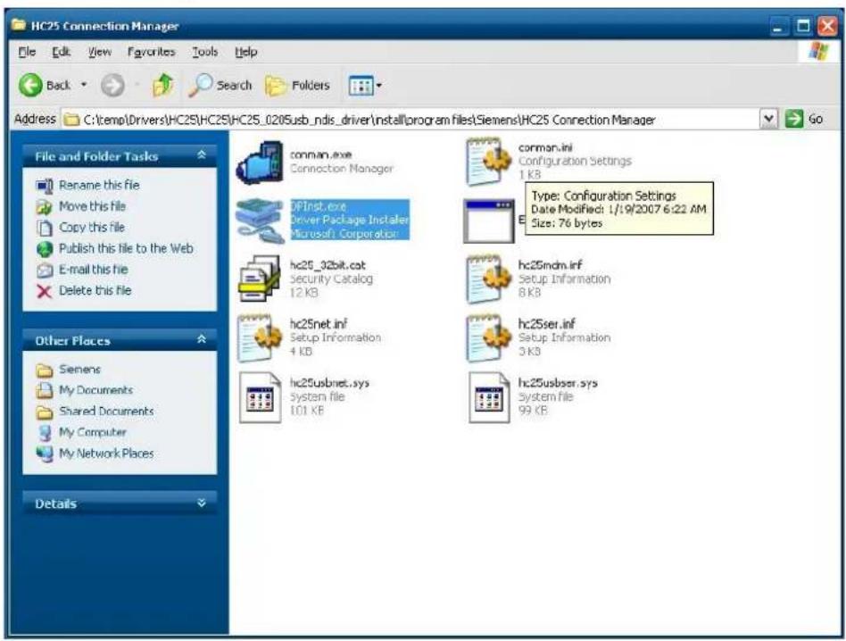
- Open the directory 'HC25\ HC25_0205ussb_ndis_driver\ install\ program files\ Siemens\ HC25 Connection Manager' and then double-click 'DPInst.exe'.
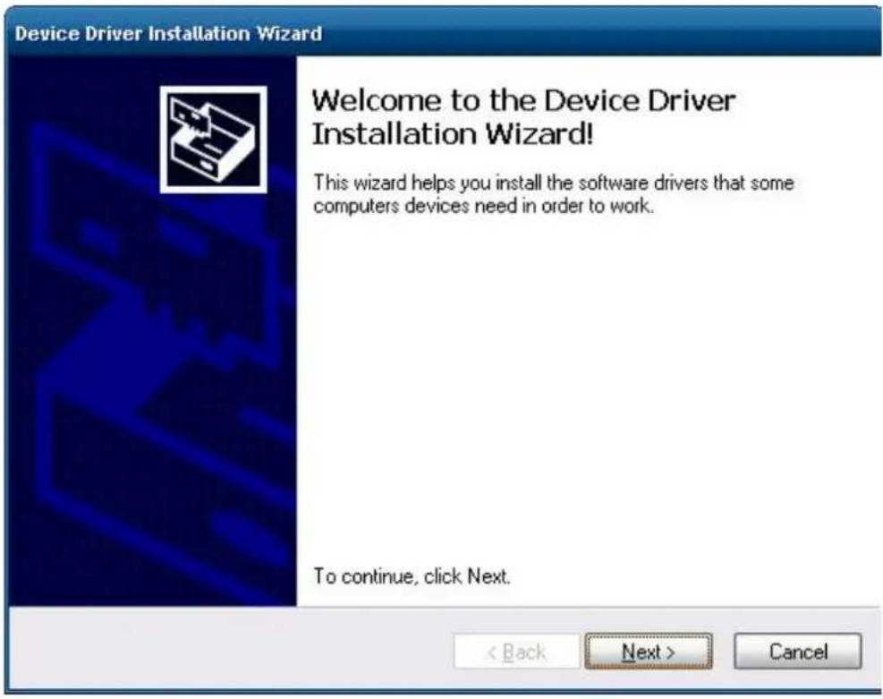
- Click 'Next'.
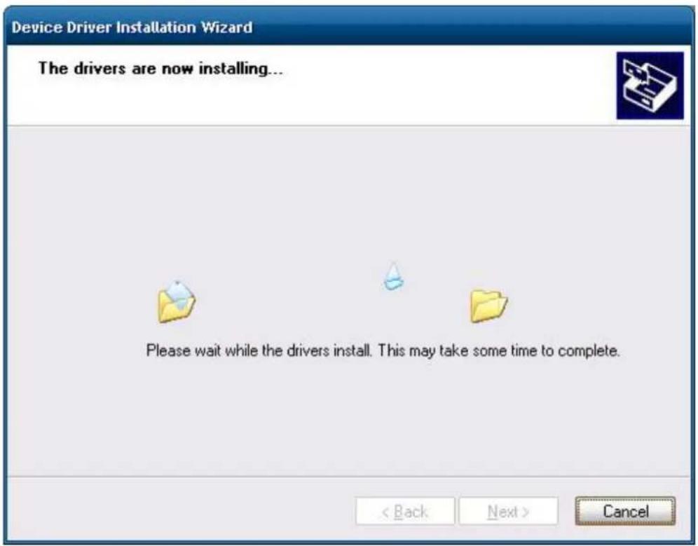
- Wait for the driver to install.
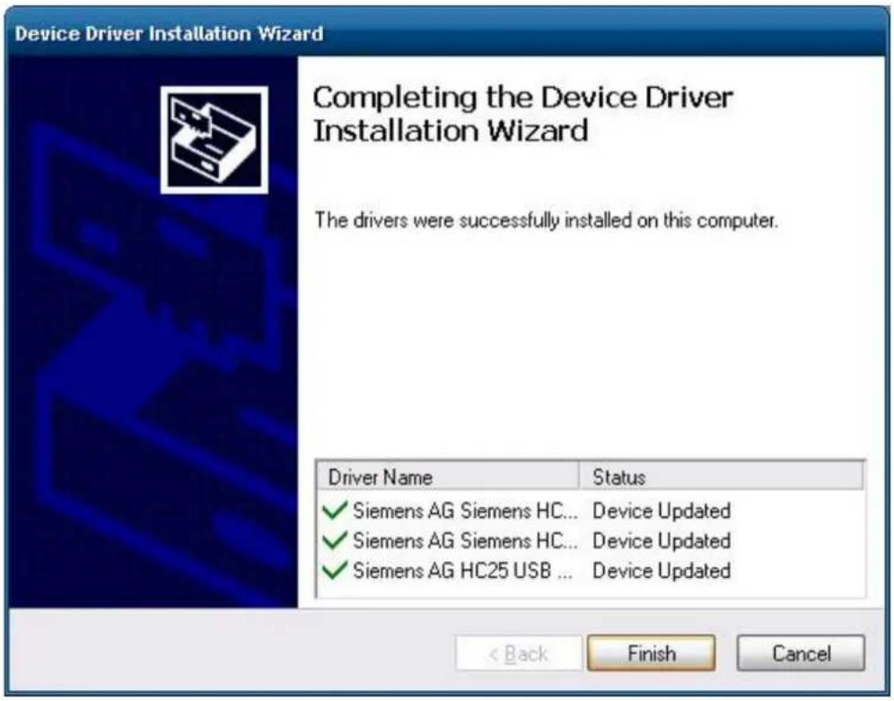
- Click 'Finish' to complete the driver installation.
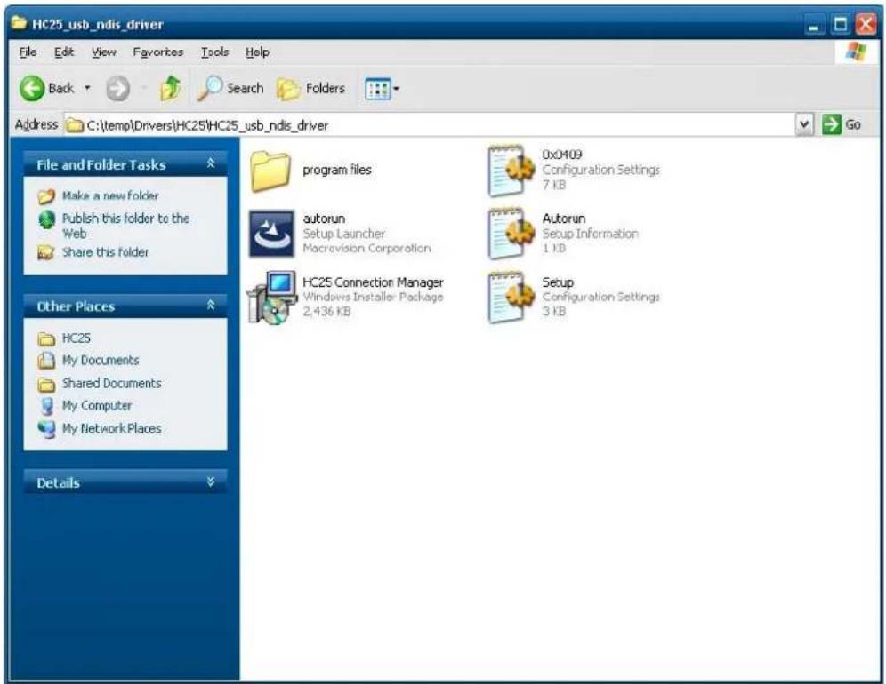
- Navigate to the '\HC25\HC25_usb_ndis_driver\program files\' directory and double-click 'HC25 Connection Manager.msi'.
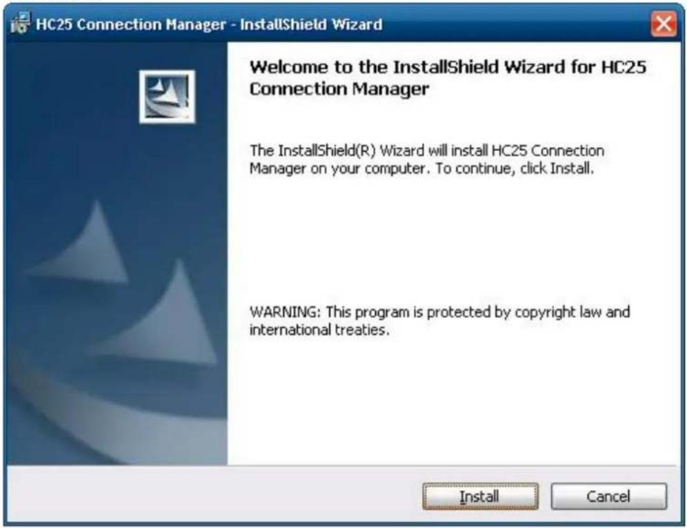
6. Click Install.
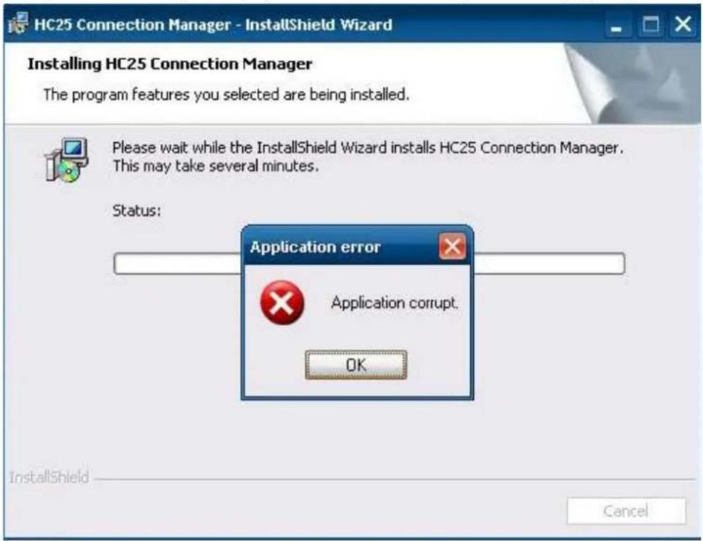
7. During the installation process, if you encounter the following error message, just ignore it and click 'OK'.
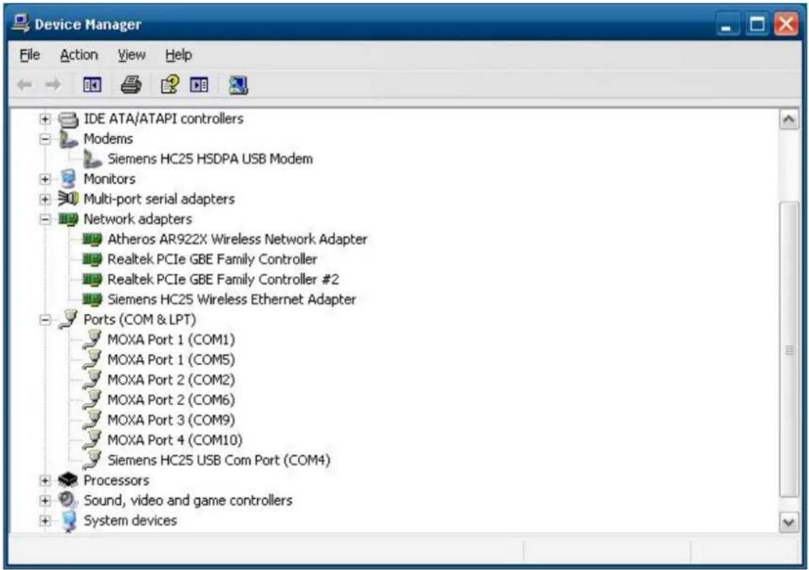
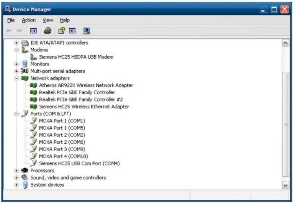
- After installation completes, you should see "Siemens HC25 HSDPA USB Modem"、"Siemens HC25 Wireless Ethernet Adapter" and "Siemens HC25 USB COM Port" in you Device Manager, as illustrated below.
- Change to the 'Winmux2K' directory and double-click 'wmux2k.exe'.
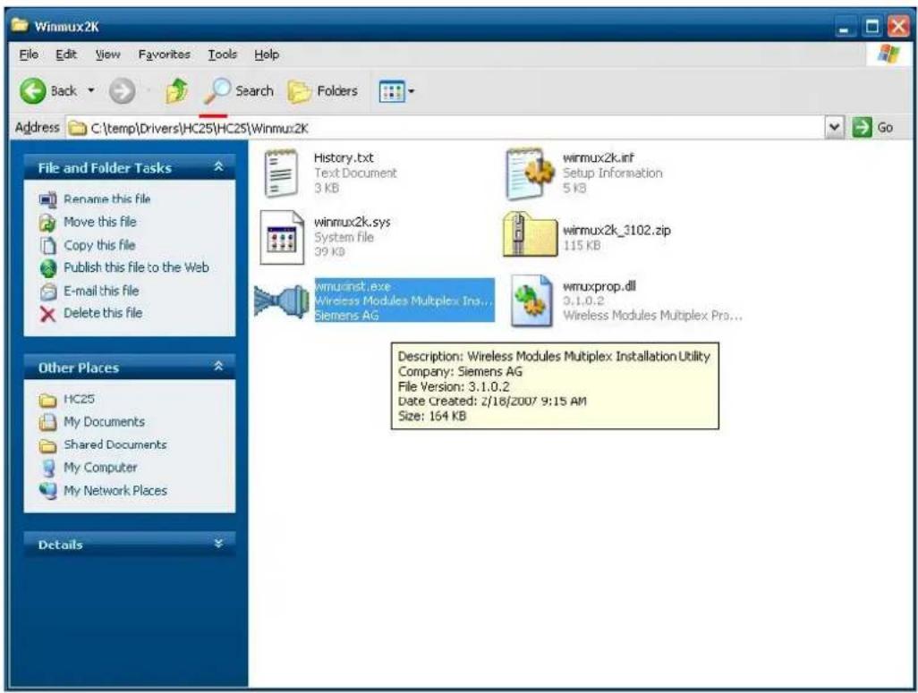
10. Click 'Start Scan'.
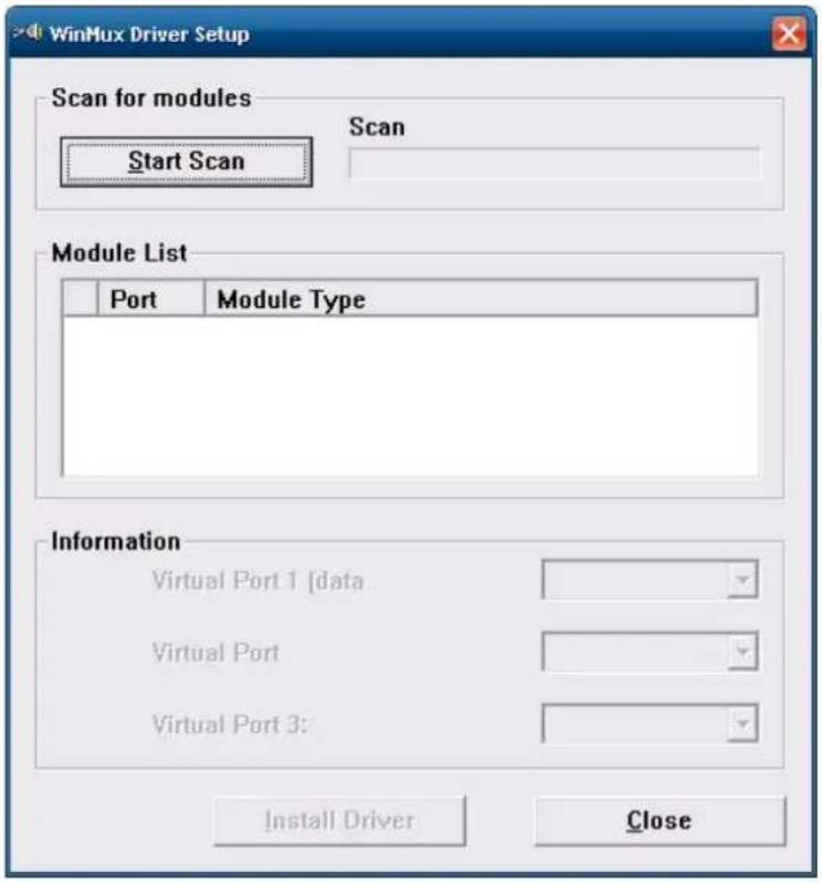
11. Click 'Install Driver' once the scan is complete.
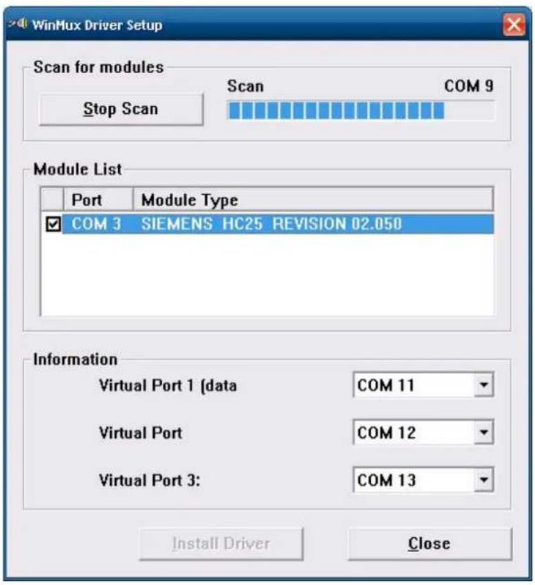
- Click 'Install Driver' and press 'Continue Anyway' once the scan is complete.
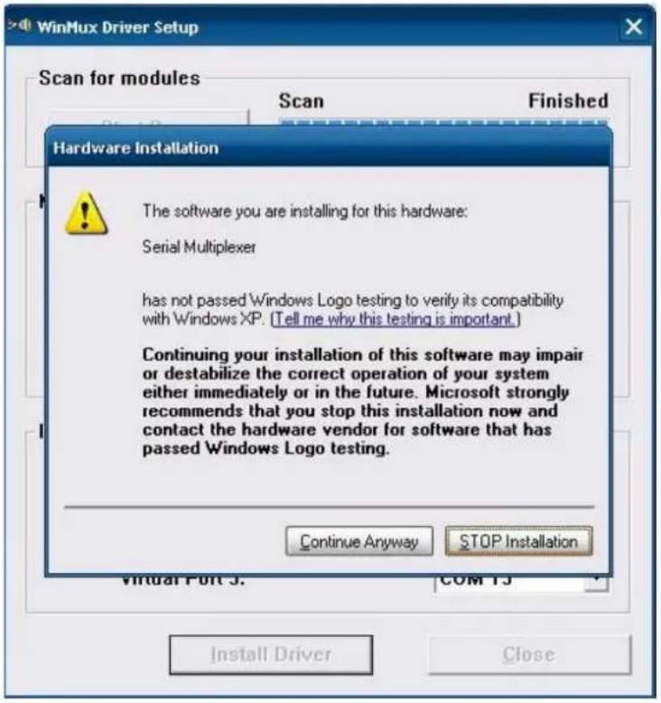
- Click [OK] to complete the installation.
![WinMux Driver Setup Scan for modules Start Scan Scan Finished Module List Port Module Type WINMux Driver Setup The WinMux driver is installed! Use the property page in the Device Manager to change the Settings! OK Virtual Port 1 [data] COM 11 Virtual Port COM 12 Virtual Port 3: COM 13 Install Driver Close](/content/2026/05/1142543/images/fc1154a3168bfc702e92d8889233dbd7e37ce583e4ed9a10b1adebf5944812bd.jpg)
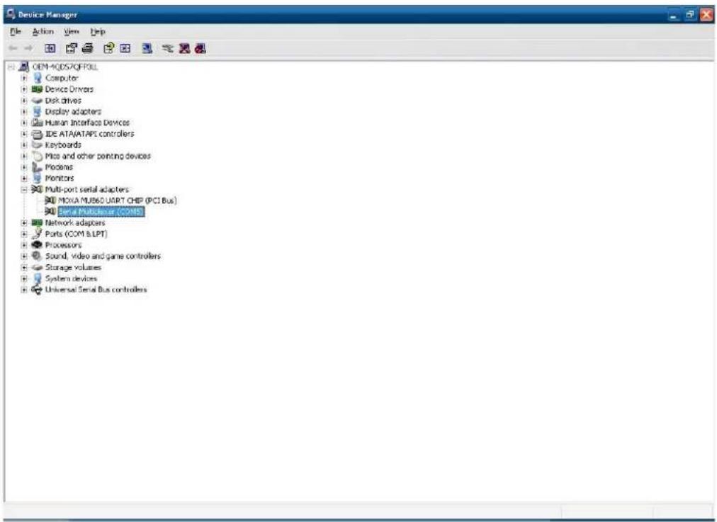
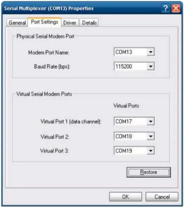
- You should see the Serial Multiplexer in your Device Manager, as illustrated below.
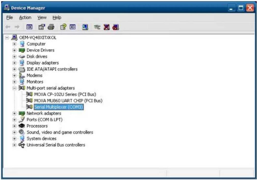
- Right-click on Serial Multiplexer and select properties. You will see that 3 virtual serial modem ports have been generated; you can change the port number using the drop-down list.
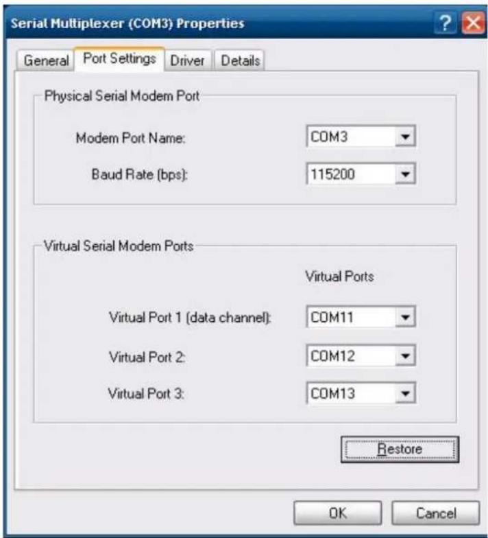
NOTE
Make sure each port name is unique; duplicate names will create glitches
Wireless Module Driver Installation
Follow the steps below to install the wireless driver
- Click 'Cancel' to stop searching for drivers when you first install the module.

- Navigate to the 'Install_CD' directory and double-click 'setup.exe' to install the driver.
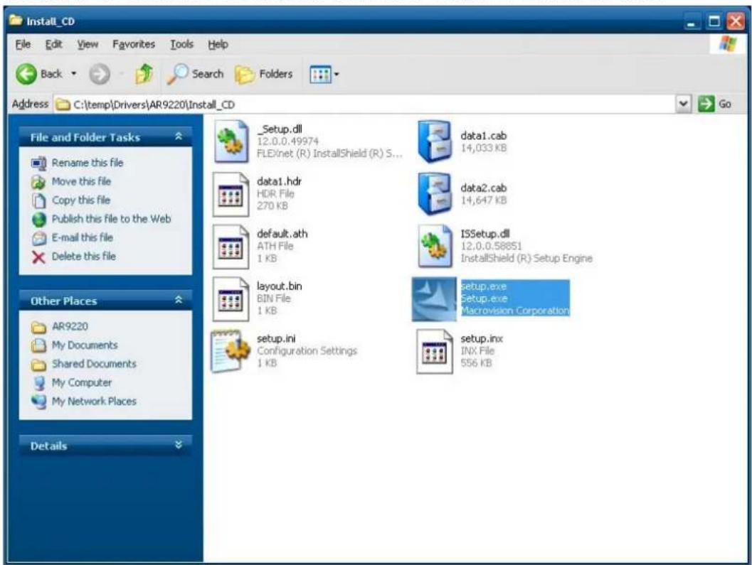
3. Click 'Next'.
4. Click 'Next'.
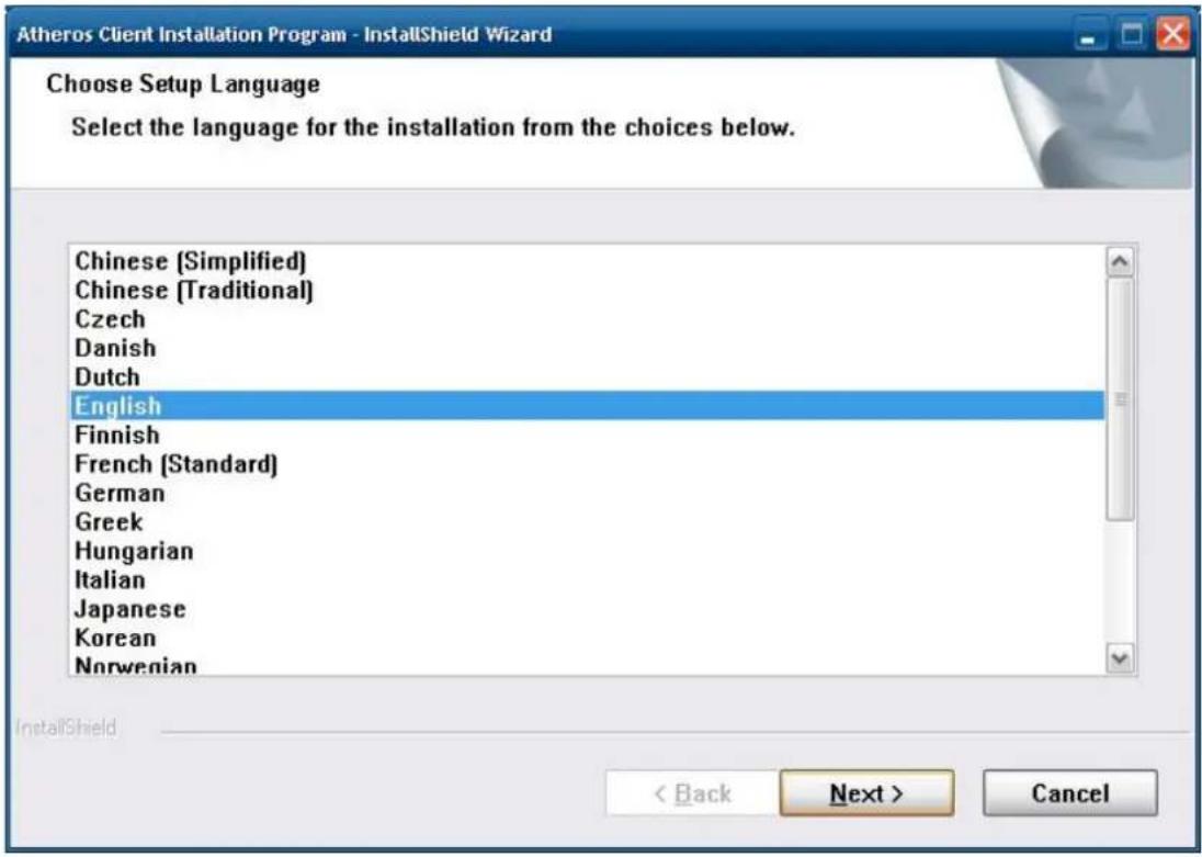
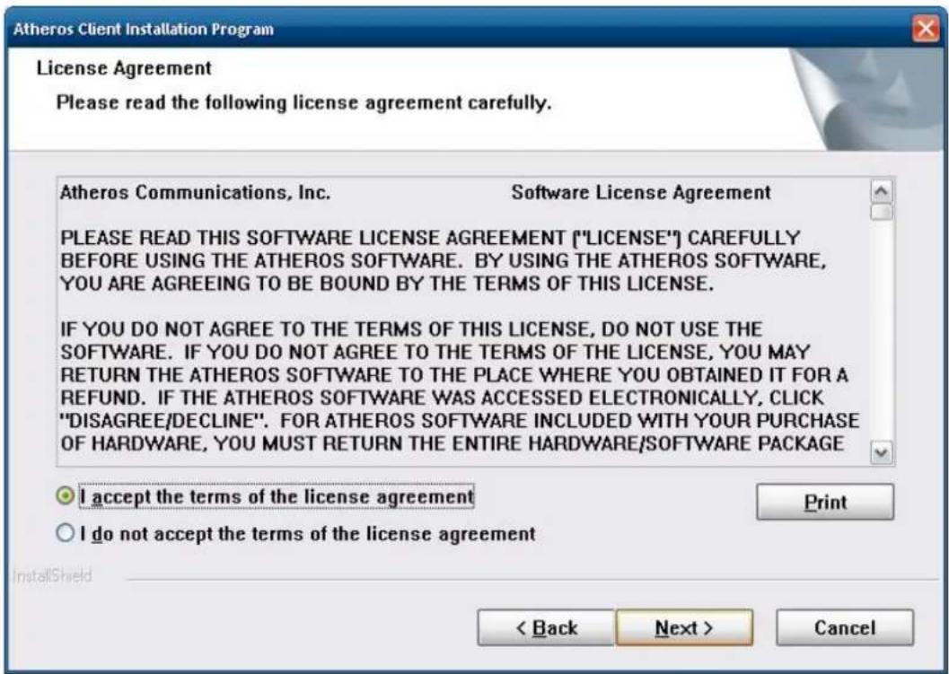
- Select 'I accept the terms of the license agreement' and then click 'Next'.
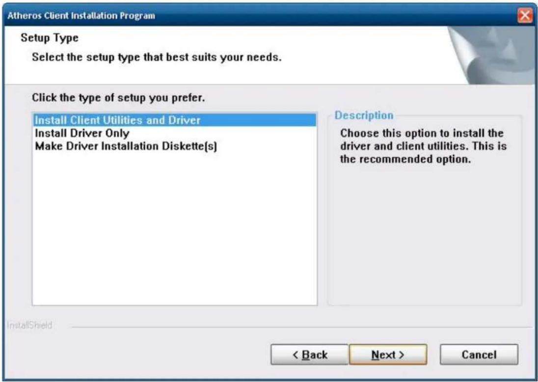
- Select 'Install Client Utilities and Driver' and then click 'Next'.
7. Click 'Next'.
8. Click 'Next'.
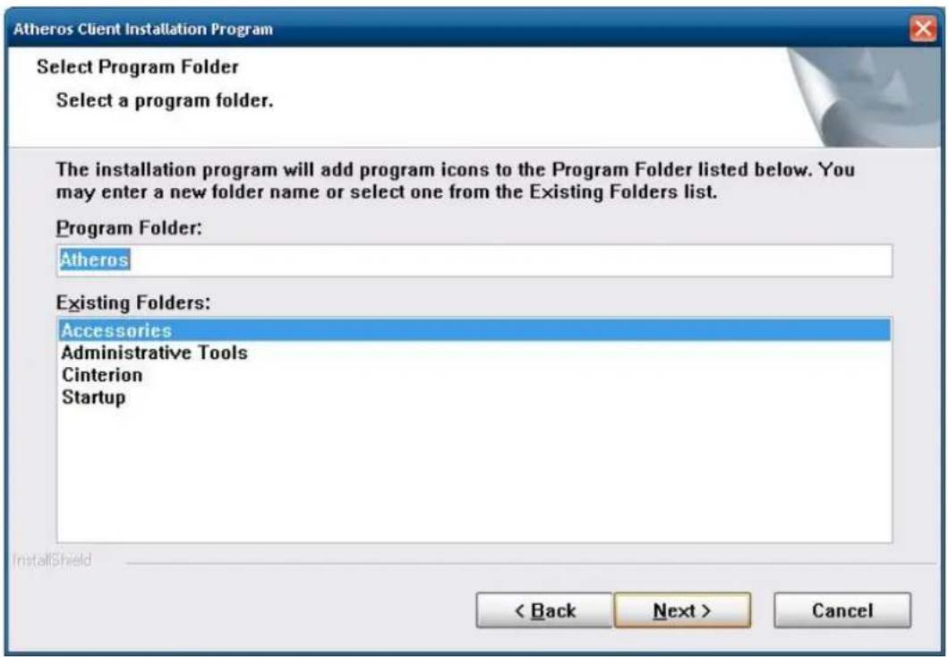
9. Click 'Next'.
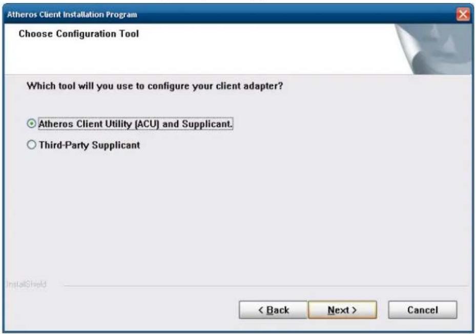
![Atheros Client Installation Program Atheros Client Installation Program IMPORTANT: Please Read! On Windows XP, you can configure your Atheros Wireless LAN Client Adapter through the Atheros Client Utility (ACU) or a third-party supplicant. Because third-party tools may not provide all of the functionality available in the ACU, Atheros recommends that you use the ACU. [Please note that a patch from Microsoft might be required to use the Microsoft tool with WPA security.] On the next screen, select whether you want to use the ACU or a third-party tool to configure your client adapter. NOTE: If you select a third-party tool, some of the ACU features will not be available. To activate those features, you must install the ACU. < Back Next > Cancel](/content/2026/05/1142543/images/1e84a836b2064656895311340dff335446fb883975dd0aa79f07e271ee90f723.jpg)
10. Select 'Atheros Client Utility (ACU) and Supplicant' and click 'Next'.
11. Click 'Yes'.

- Click 'OK'.

- Wait for the driver to install.
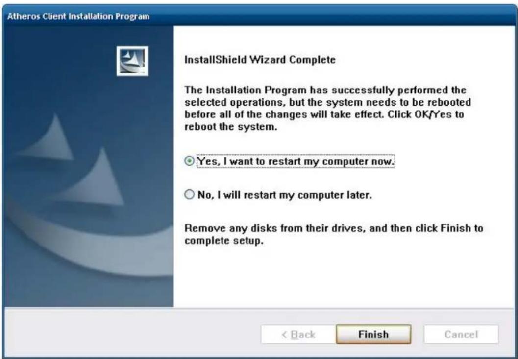
- Select 'Yes, I want to restart my computer now' and click 'Finish'.
- After installation completes, you will find the 'Siemens HC25 HSDPA USB Modem," Siemens HC25 Wireless Ethernet Adapter, and 'Siemens HC25 USB COM Port' in Device Manager.
Configuring the GPRS/ HSDPA Connection (without GPS)
This section illustrates how to establish a connection with the 'Siemens HC25 Connection Manager' utility.
Follow the steps below to configure 3G/GPS and the wireless driver
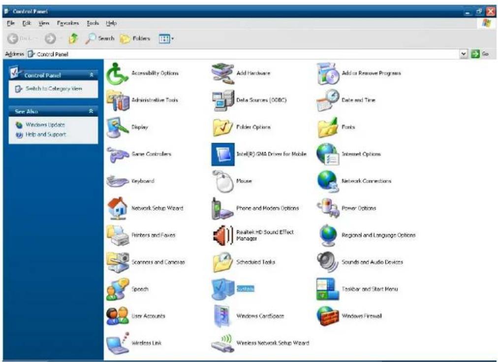
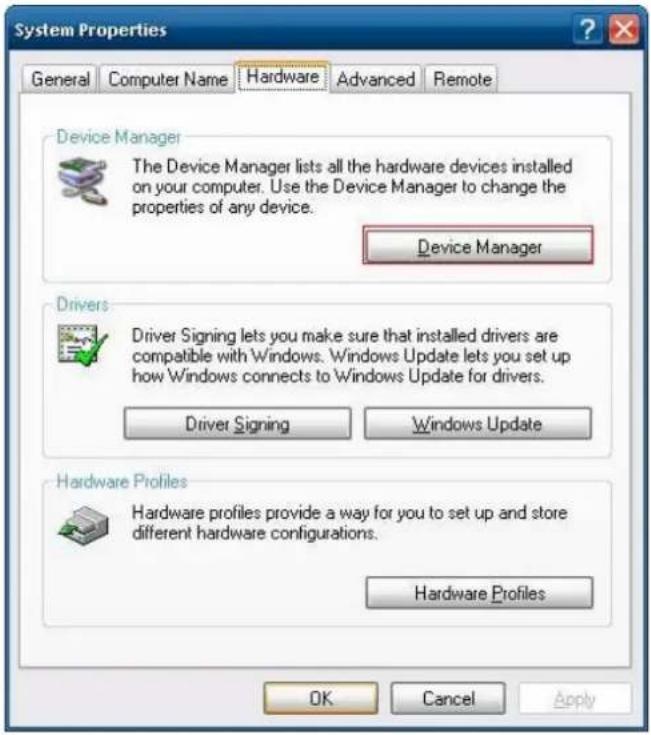
- Go to the Control Panel->System.
2. Click Hardware -> Device Manager
3. Right-click Serial Multiplexer->Properties->Port Settings

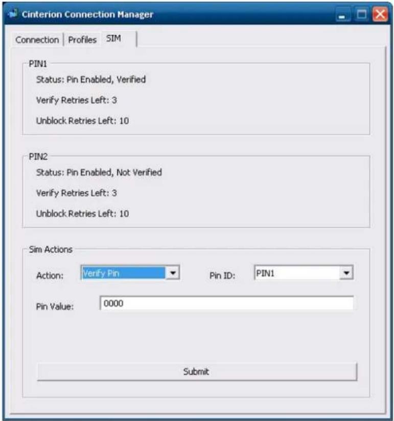
- Open Virtual Port 2 (Ex. COM12) and enter 'at+cpin?' Make sure that the SIM card status is ready or the connection may fail.
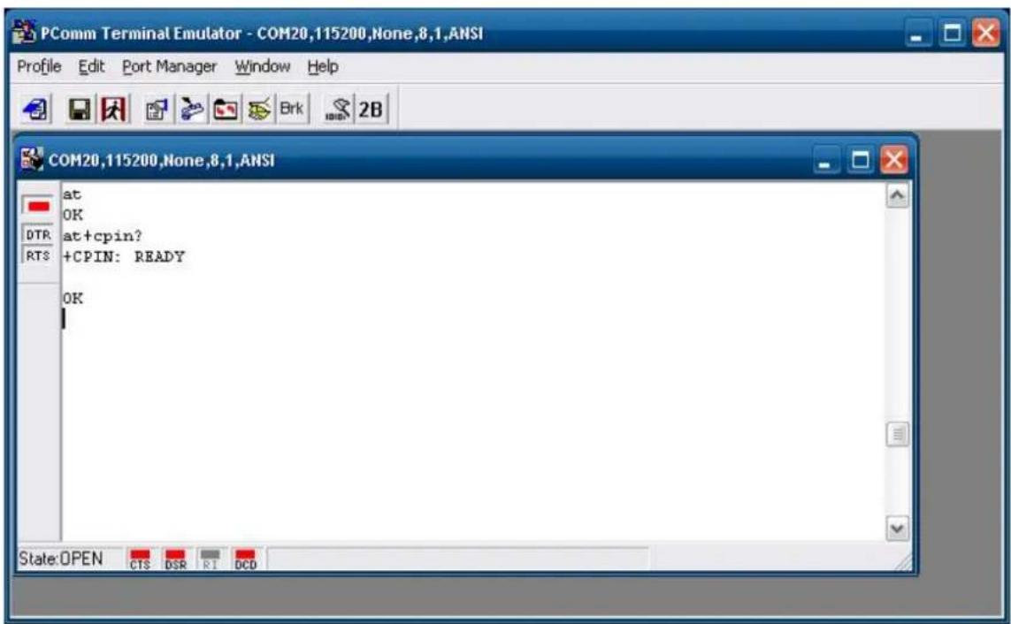
NOTE Before you verify SIM card status, please check whether or not the PIN code is submitted,
- Select the device from the drop-down list and enter the APN Name.
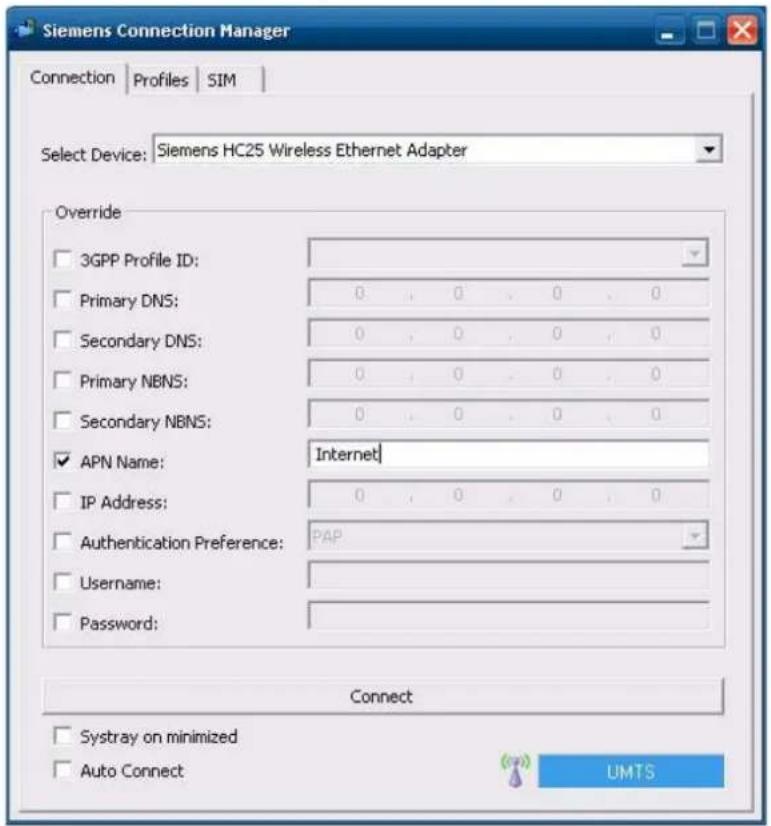
- Click 'Connect' to connect to internet and the wireless connection will be established.
NOTE
Do not close the program while the connection is established or the device driver may not work properly.
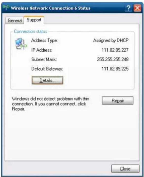
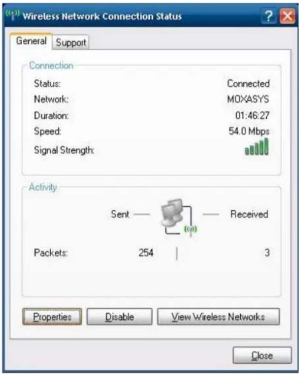
- Now you can access this wireless network connection.
![Microsoft Windows XP [Version 5.1.2600] (C) Copyright 1985-2001 Microsoft Corp. C:\Documents and Settings\Administrator>ping www.google.com.tw Pinging www.1.google.com [72.14.203.99] with 32 bytes of data: Reply from 72.14.203.99: bytes=32 time=200ms TTL=51 Reply from 72.14.203.99: bytes=32 time=181ms TTL=51 Reply from 72.14.203.99: bytes=32 time=203ms TTL=51 Reply from 72.14.203.99: bytes=32 time=142ms TTL=51 Ping statistics for 72.14.203.99: Packets: Sent = 4, Received = 4, Lost = 0 (0% loss), Approximate round trip times in milli-seconds: Minimum = 142ms, Maximum = 203ms, Average = 181ms C:\Documents and Settings\Administrator>](/content/2026/05/1142543/images/356a2ce402af4c2793f27d8d1dd06b71d93c14c08c4cb87261bfba1b151cdda1.jpg)
Enabling GPS Functionality
GPS functionality is only enabled in the multiplexer mode of the module. A "Winmux2K" driver is offered to configure the module in multiplexer mode. In multiplexer mode, the system will generate virtual COM ports to communicate. Therefore, the modem port becomes one of the virtual COM ports.
This section describes how to set up GPS functionality.
Follow the steps below to enable GPS functionality.
- Open 'Device Manager' and check the relative COM ports.
- Open 'Terminal Emulator' and open GPS relative ports.
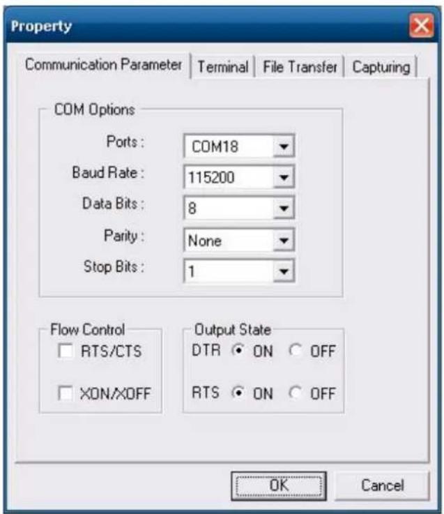
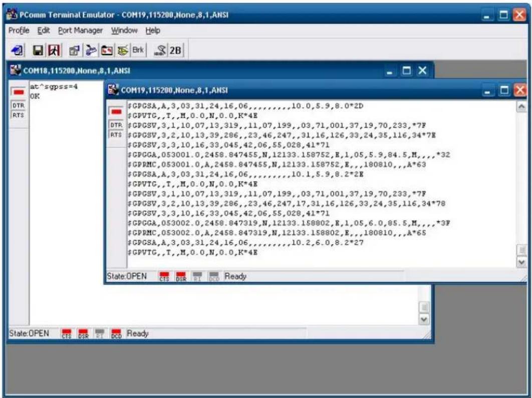
3. Enter 'at^ sgpss=4' to enable GPS functionality
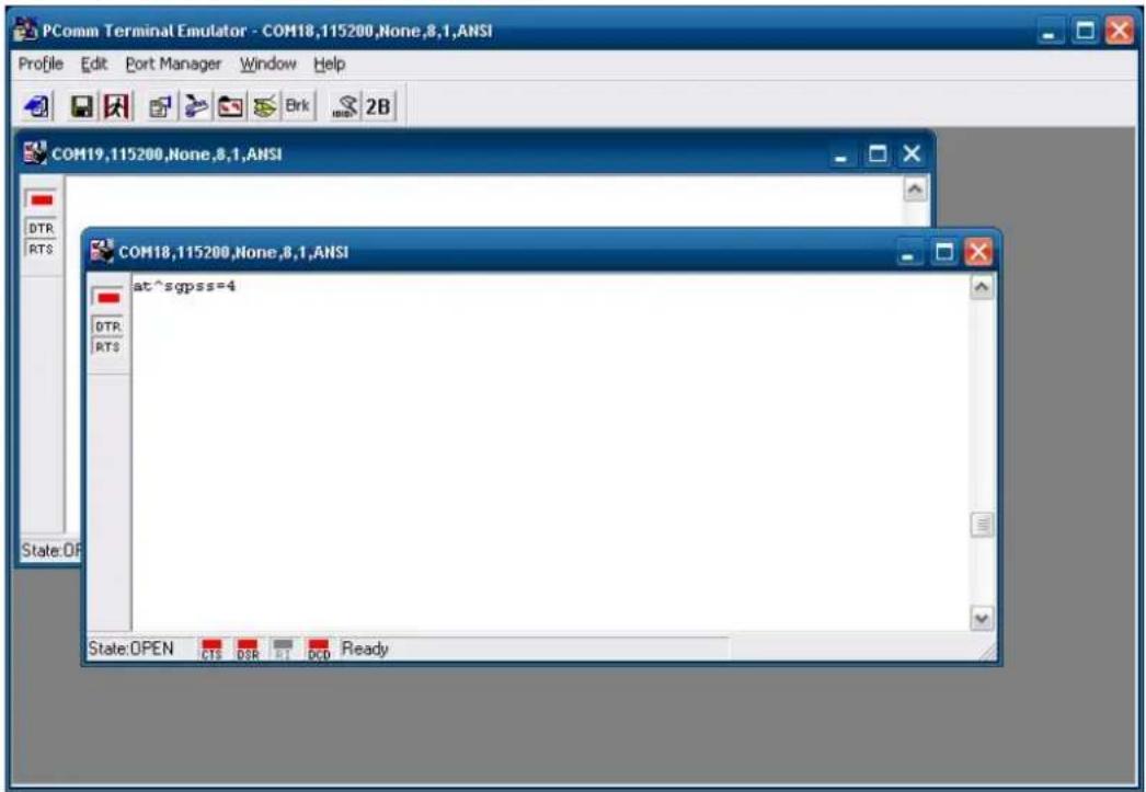
4. Receive the information returned through GPS and verify that the position value is correct.
Configuring a Wireless Connection
The EPM-3337 module includes a wireless module. This section explains how to connect to an access point with WEP/WPA/WPA2(RSN) encryption.
Follow the steps below to configure a wireless connection
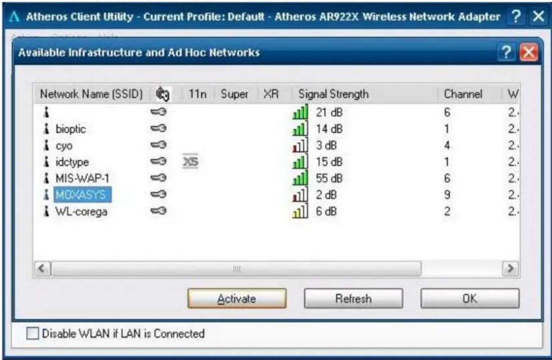
- Double-click on the 'Atheros client utility' shortcut on the desktop. Click on the 'Profile Management' tab, and then click 'SCAN' button.
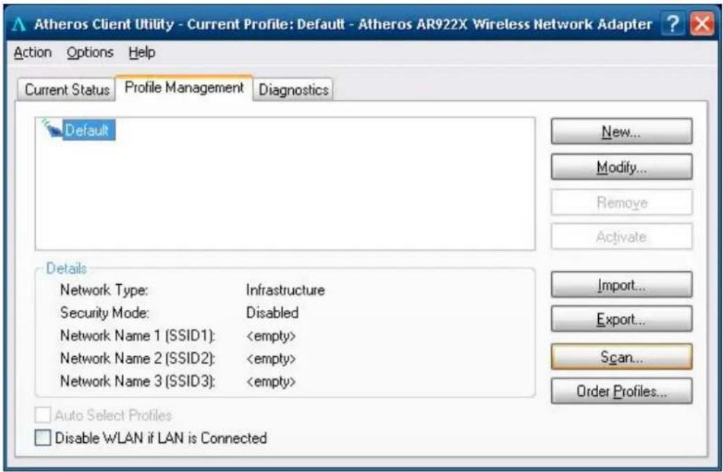
- Select the access point which you want to connect to and click 'Activate'.
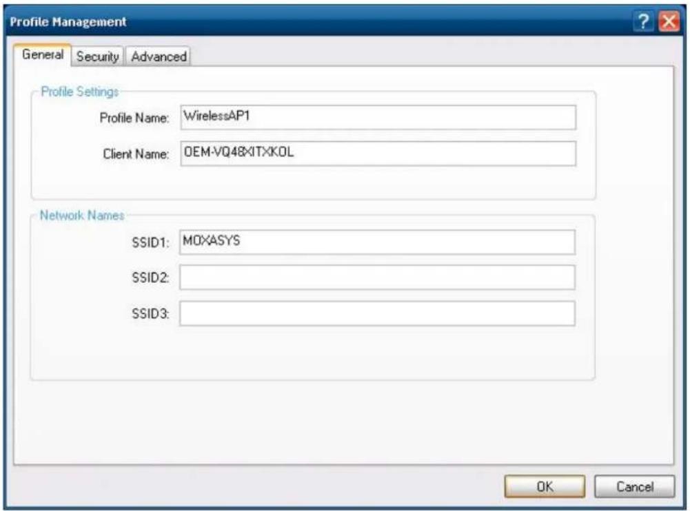
- Enter the Profile Name. Then, select the Security tab.
- Select the security option for your network. Then, click 'Configure'.
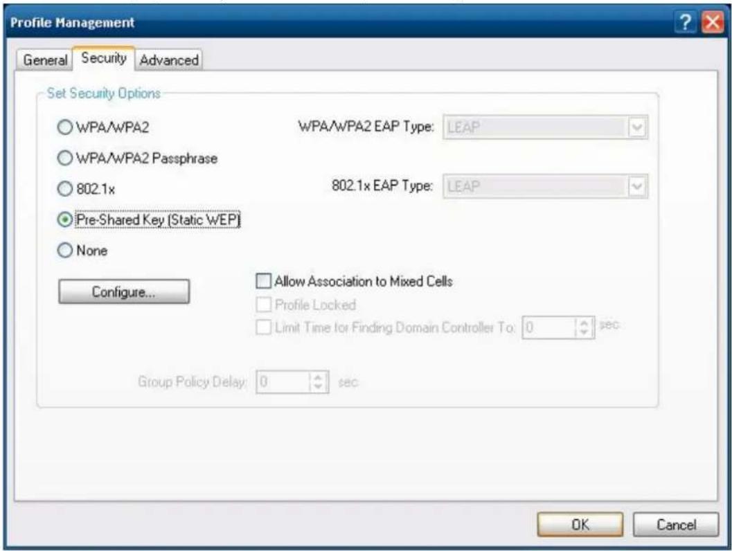
5. Enter the password.
![Profile Management General Security Advanced Configure Pre-Shared Keys (Static WEP) Key Entry Hexadecimal [0-9, A-F] ASCII Text (all keyboard characters) Encryption Keys Transmit Key WEP Key Size: 64 128 152 WEP Key 1: 1234567890 WEP Key 2: WEP Key 3: WEP Key 4: OK Cancel OK Cancel](/content/2026/05/1142543/images/b7c4fd81bcb7f2416b800a16009ecd63456bf27c1dcd2dd19385ab21e86c09ca.jpg)
6. The connection will now be established.
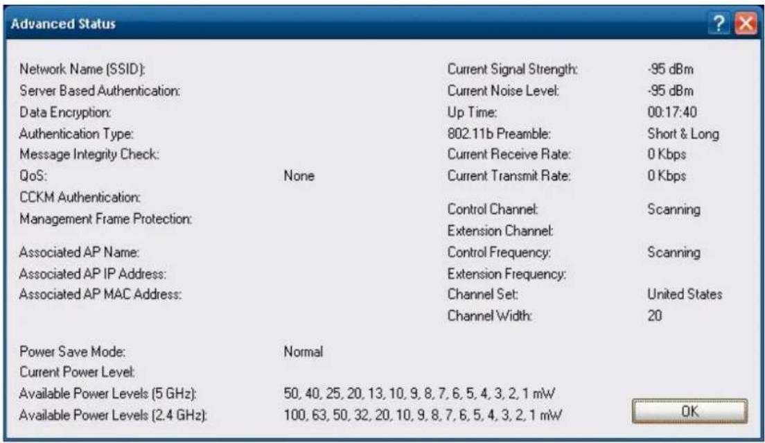
Getting Wireless Module Information
The 'Atheros Client Utility' helps you to get wireless information and manage wireless connections.
- Double-click the 'Atheros client utility' shortcut on the desktop and change to the 'Current Status' tab.
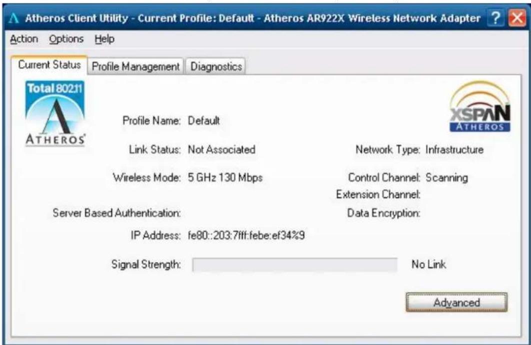
- Click the 'Advanced' button. You will see current wireless connection status.
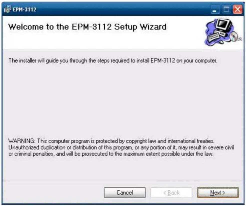
EPM-3112 Driver Installation
Take the following steps to install the CANBUS driver:
- Double-click EPM-3112_V1.0.msi to install the module driver and then click Next.
- Click Next to continue.
- Click Next to start the driver installation.
- Click Close to complete the driver installation.
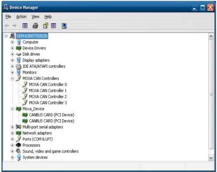
- Click Action → Scan for hardware change to install the module driver automatically.
EPM-3112 Programming Guide
CANBUS Library
| int mxcan_close (int fd) | |
| Description Close an open port. | |
| Inputthe open port | |
| Return Value None |
| unsigned int mxcan_get_bus_timing (int fd) | |
| Description Gets the bus timing of an open port. | |
| Inputthe open port | |
| Return Value 0 on failure, otherwise the bus speed in KHz |
| int mxcan_get_parameters (int fd, CANPRM * param) | |
| Description Get$ the parameter of an open port. | |
| Input <fd> the open port | |
| Output <param> pointer to the CANPRM structure | |
| Return Value 0 on failure, otherwise returns a negative value |
| int mxcan_get_registers (int fd, unsigned char * buffer, int num) | |
| Description Gets the register values of an open port. | |
| Inputthe open port | |
| Output < buffer> pointer to a buffer for these values<num> number of register values; for a module with sja1000 chipset, the value must be 32 | |
| Return Value 0 on success; other numbers indicate failure | |
| int mxcan_get_stat (int fd, CANBST * stat) | |
| Description Gets the statistics of an open port. | |
| Inputtheopen port | |
| Outputpointer to a container of the statistics | |
| Return Value 0on success; other numbers indicate failure |
| Int mxcan_inqueue (int fd) | |
| Description | Gets the number of received bytes that are queued in the driver of an open port. |
| Input <fd> the | open port |
| Return Value 0 | on failure; otherwise the number of bytes |
| int mxcan_open (int port) | |
| Description Open | a can port given the port number. |
| Inputport number starting from 1; in Linux, open port 1 will open /dev/can0 | port number starting from 1; in Linux, open port 1 will open /dev/can0 |
| Return Value -1 | on failure; otherwise returns fd |
| int mxcan_outqueue (int fd) | |
| Description Gets | the number of bytes waiting to be transmitted to a can port. |
| Inputthe | open port |
| Return Value -1 | on failure; otherwise the number of bytes |
| int mxcan_purge_buffer (int fd, unsigned int purge) | |
| Description Purges the buffers of an open port. | |
| Inputtheopen port | |
| Output<purge>1: received data buffer; 2: transmit data buffer; otherwise: both | |
| Return Value 0 on success; otherwise failure |
| int mxcan_read (int fd, char * buffer, int size) | |
| Description Reads data into a buffer from an open port (the size should be a multiple of the CANMSG size) | |
| Inputtheopen port | |
| Outputpointer to the buffer | |
| Return Value 0 on failure (data not available); otherwise the number of bytes read |
| int mxcan_set_bus_timing (int fd, unsigned int speed) | |
| Description Sets | the bus timing of an open port. |
| Inputthe | open port |
| Outputbus timing in Hz | bus timing in Hz |
| Return Value 0 | on success; otherwise returns a negative number |
| int mxcan_set_nonblocking (int fd) | |
| Description Sets | the open fd to be non-blocking. |
| Inputthe | open port |
| Return Value 0 | on success; otherwise returns a negative number |
| int mxcan_set_parameters (int fd, CANPRM * param) | |
| Description Sets the parameters of an open port. | |
| Inputthe | open portpointer to the CANPRM structure |
| Outputbus timing in Hz | |
| Return Value 0 | on success; otherwise returns a negative number |
| int mxcan_set_read_timeout (int fd, unsigned int to) | |
| Description Sets | data reading timeout of an open port. |
| Inputthe | open porttimeout in milliseconds |
| Return Value 0 | on success; otherwise failure |
| int mxcan_set_write_timeout (int fd, unsigned int to) | |
| Description Sets data writing timeout of an open port. | |
| Inputthe | open porttimeout in milliseconds |
| Return Value 0 | on success; otherwise failure |
| int mxcan_write (int fd, char * buffer, int size) | |
| Description Writes data to the open port | |
| Inputthe | open portpointer to the datasize of the data (should be a multiple of the CANMSG size) |
| Return Value 0 | on failure; otherwise the number of bytes written |