IX 539/A - Audio Amplifier PLANTRONICS - Free user manual and instructions
Find the device manual for free IX 539/A PLANTRONICS in PDF.

| Product Type | Audio Amplifier |
| Brand | Plantronics |
| Model | IX 539/A |
| Dimensions (approx.) | 150 x 100 x 50 mm |
| Weight (approx.) | 0.5 kg |
| Power Supply | 12V DC, 1A |
| Power Consumption | 10 W |
| Input Impedance | 10 kΩ |
| Output Power | 2 x 10 W RMS |
| Frequency Response | 20 Hz - 20 kHz |
| Total Harmonic Distortion | < 0.1% |
| Input Connectors | 3.5 mm stereo jack, RCA |
| Output Connectors | Speaker terminals, 3.5 mm headphone jack |
| Controls | Volume, bass, treble, power switch |
| Indicators | Power LED |
| Protection Features | Short circuit, overheat |
| Operating Temperature | 0°C to 40°C |
| Housing Material | Metal |
| Maintenance | Clean with soft dry cloth. Do not use solvents. |
| Safety Precautions | Keep away from moisture. Do not open the device. |
| Spare Parts Availability | Contact Plantronics support for replacement parts. |
| Repairability | Device should be serviced by qualified personnel. |
Frequently Asked Questions - IX 539/A PLANTRONICS
User questions about IX 539/A PLANTRONICS
0 question about this device. Answer the ones you know or ask your own.
Ask a new question about this device
Download the instructions for your Audio Amplifier in PDF format for free! Find your manual IX 539/A - PLANTRONICS and take your electronic device back in hand. On this page are published all the documents necessary for the use of your device. IX 539/A by PLANTRONICS.
USER MANUAL IX 539/A PLANTRONICS
VISTA cov.eng.mech 9/16/02 5:18 PM Page 30

text_image
Vista™ Universal Modular Amplifier M12 345 Encinal Street Santa Cruz CA 95060 Tel 1.800.544.4660 www.plantronics.com User's Guide Printed in USA © 1998 Plantronics, Inc. PLANTRONICS 43346-01 (9+98) PLANTRONICSwelcome
to the Vista ^™ Universal Modular Amplifier from Plantronics ^® .
The Vista Universal Modular Amplifier adapts your telephone to a Plantronics headset and provides control of the sound through your headset. The Vista amplifier has built-in sound conditioning and protection.
This User Guide will help you install your Vista amplifier and learn its basic operations.
The Vista amplifier is not designed to work on telephones that have the dial pad in the handset or on cordless telephones.
PART I Install in 4 easy Steps
Step 1: Install batteries.
Step 2: Attach to phone and headset.
Step 3: Set default settings.
Step 4: Set telephone/amplifier compatibility switch.
PART II Make a test call.
PART III Learn the basics.
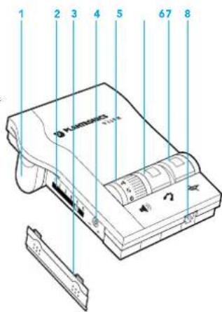
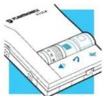
Vista™
Universal Modular Amplifier
1 Battery Access Door
2 Telephone/Amplifier Compatibility Slide Switch
3 Telephone/Amplifier Compatibility Slide Switch Cover
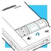
4 Outgoing Volume Control
5 Incoming Volume Thumbwheel
2 6 Headset/Handset Selector
7 Mute 8 Headset Jack
1 Telephone Jack
2 Screwdriver
3 Handset Jack
4 AC Power Supply Jack
5 AC Power Supply
6 Amplifier to QD Coil Cable
7 Amplifier to Telephone Coil Cable
text_image
1 2 3 4 5 6 7 8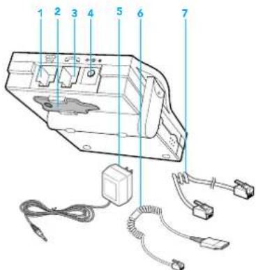
text_image
Technical diagram of an electronic device with numbered components and wiring connectionsenglish iii
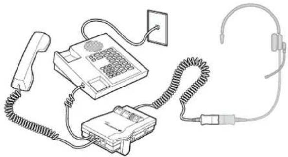
connections
& features
Connect the Vista amplifier to your telephone as shown. Follow the four easy steps on the following pages for complete installation details.
natural_image
Line drawing of a telephone handset, keypad, and ear with coiled cord (no text or symbols)Amplifier Features
- SoundGuard® Plus™ Sound Compression protects you from harsh noises, such as fax tones
- Call Clarity™ System improves incoming and outgoing sound
- Switch easily between headset and handset
• Incoming and outgoing volume control
Mute
PART
in 4 easy steps
install
text_image
1 2 3 assoc. displays 5° opt. 3° opt. 1.75 opt serrate or knurl 5° .75 opt. .75 opt. .25 min.INSTALL BATTERIES
ATTACH TO PHONE AND HEADSET
SET DEFAULT SETTINGS
SET TELEPHONE/AMPLIFIER COMPATIBILITY SWITCH
INSTALLATION STEPS
INSTALLATION STEPS
STEP 1 install
batteries
The Vista Amplifier requires power to work with most phones.
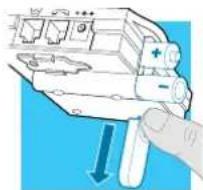
- Remove the Battery Access Door located on the side of the amplifier by placing your thumb on the door and pushing down.
- Install two AA alkaline batteries and replace the door.
- You will hear three "beeps" through the headset when the batteries are low.
STEP2 attach to
phone and headset
- Unplug your telephone's handset cord from the telephone base.
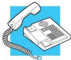
natural_image
Illustration of a classic office telephone with cord and keypad (no text or symbols)- Plug your telephone's handset cord into the Vista amplifier handset jack (↘).
- Connect your telephone base to the Vista amplifier telephone jack (☐) using the short curly cord. On your telephone base, plug the short curly cord into the outlet normally used for your handset.
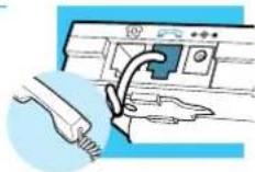
natural_image
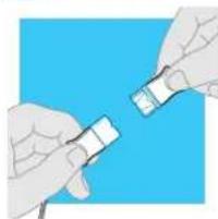
Illustration of a printer's internal components being inserted into a paper airplane (no text or symbols visible)- Plug the headset cord into the Quick Disconnect™ (QD) module on the long curly cord coming from the front of the amplifier. The QD will allow you to disconnect the headset from the amplifier when you are not using the phone, or need to move away from the amplifier, while leaving your headset in place.
natural_image
Illustration of two hands holding a small object against a blue background (no text or symbols)INSTALLATION STEPS
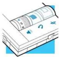
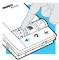
STEP3 set default settings
These are the default settings for headset use.
text_image
Diagram of a printer or scanner with labeled parts and icons, showing page number 4, page 5, and page 6.- Headset /Handset Selector is depressed (colored indicator showing).
- Mute Switch is released (no colored indicator showing).
- Incoming Volume Thumbwheel is set to 4.
- The Outgoing volume has been pre-set. You can adjust it when you place your first call (see page 6).
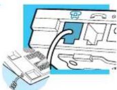
natural_image
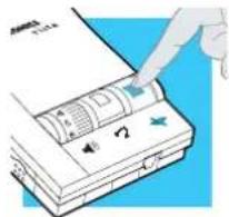
Close-up of a mechanical device's handle and lever mechanism (no text or symbols visible)STEP4 set telephone/amplifier Compatibility Switch
- Put on headset.
- Lift the phone's handset off the cradle and place it on your desk.
-
If you don't hear a dial tone, adjust the Telephone/Amplifier Compatibility Switch as indicated below:
-
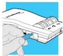
Remove the Telephone Compatibility Switch Access Door by placing two fingers or thumbs on the raised bumps and pushing down.
-
Remove the flat, plastic screwdriver from the bottom of the amplifier by sliding it through the braces holding it in place.
-
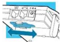
Make sure the amplifier is in the default settings, and your telephone handset is off of its cradle.
-
Using the screwdriver, slide the Compatibility Switch until you hear a clear dial tone. Experimenting with various switch settings will not harm the amplifier or your telephone.
natural_image
Illustration of a medical device with earphones and a telephone, no text or symbols present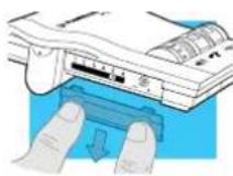

text_image
PART II make a test call 3.5 4 2 80° max. 45° 45° 2.7 3.8 4.2 palm lg. 4.7 3.7 4.1 4.5 2.7 27° 40° 25° 66° 79° 3.0 dorsum lg. 4.5 3 d.finger lg. 85 av. 1.03 max. 875 max. 15° ± lunateMAKE A TEST CALL.
- Put on headset. Refer to your headset's User Guide to adjust the microphone position for best performance.
- Lift the phone's handset off the cradle and place it on your desk.
- Make sure your Vista amplifier settings are in default. See page 4 for details.
- Call a friend or colleague.
- Adjust the Incoming Volume using the Incoming Volume Thumbwheel. Refer to page 10 for more details.
- Adjust the Outgoing Volume Control until the person on the other end can hear your voice at an appropriate level. See page 10 for more details.
- If your friend cannot hear you, or you hear a buzz or hum, try changing the Compatibility Switch. See page 5 for more details.
- Try activating the Mute function by depressing the Mute Switch (colored indicator showing). Release the Mute Switch (no colored indicator showing) to deactivate the Mute function. See page 11 for more details.
- If you used batteries in your Vista amplifier, try removing the batteries. If you lose power, your phone model requires power for your Vista amplifier. Replace the batteries.
text_image
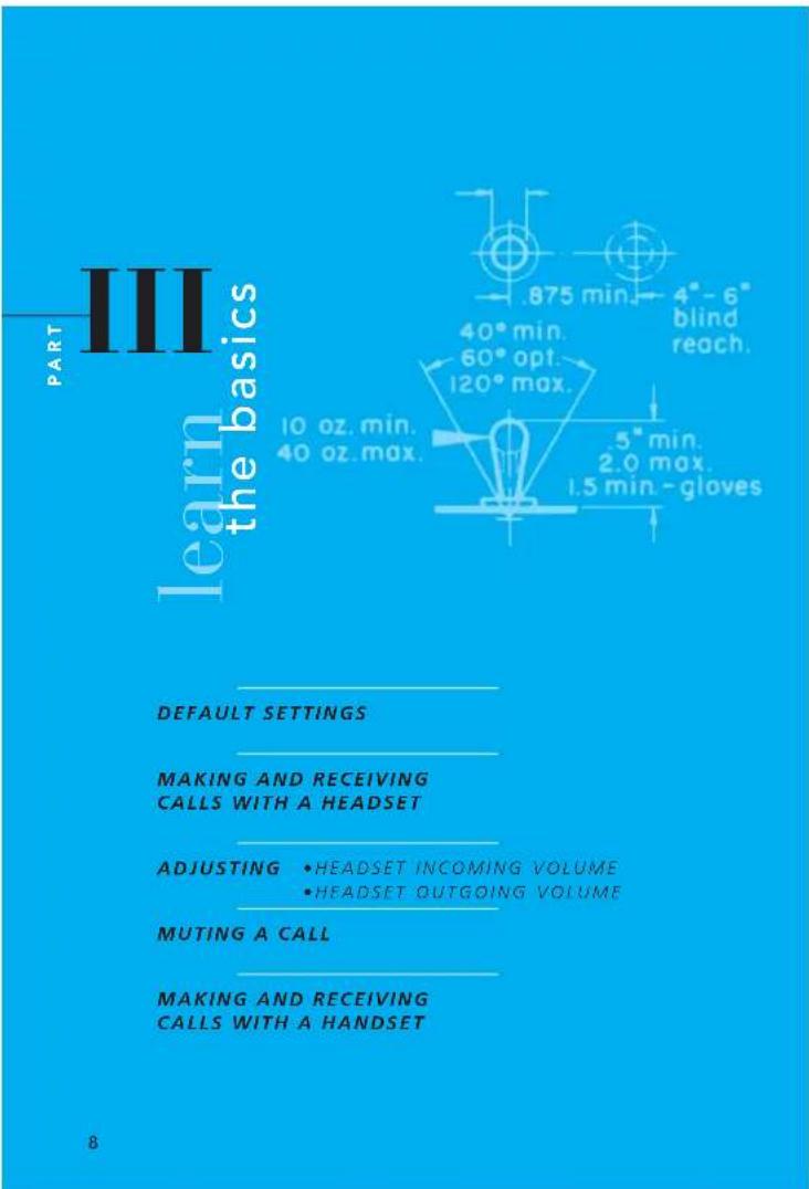
PART III learn the basics 875 min. 4"-6" blind reach. 40° min. 60° opt. 120° max. 5" min. 2.0 max. 1.5 min.-gloves 10 oz. min. 40 oz. max. DEFAULT SETTINGS MAKING AND RECEIVING CALLS WITH A HEADSET ADJUSTING • HEADSET INCOMING VOLUME • HEADSET OUTGOING VOLUME MUTING A CALL MAKING AND RECEIVING CALLS WITH A HANDSET 8LEARN THE BASICS.
Default settings
These are the default settings for headset use:
- Headset /Handset Selector is depressed (colored indicator showing).
- Mute Switch is released (no colored indicator showing).
- Incoming Volume Thumbwheel is set to 4.
Making and Receiving Calls with a Headset
- Put on headset.
- Make sure the amplifier settings are in default.
- Lift the phone handset off the cradle and place on your desk.
- Make or receive your call. You will use the dial pad and/or other features of your telephone as you would normally.
- To end the call, hang up the handset.
text_image
Diagram of a printer with labeled components and icons, showing paper and print layout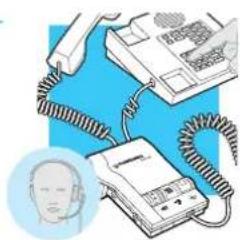
natural_image
Illustration of a medical device with coiled tubing and a head icon (no text or symbols)LEARN THE BASICS
LEARN THE BASICS
text_image
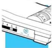
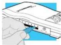
Diagram showing a hand inserting a device into a device with labeled components and arrows indicating insertion direction.Adjusting Headset Incoming Volume
- Adjust the volume by turning the Thumbwheel on the top panel.
- Try different volume settings. 1 is the quietest and 9 is the loudest.
- "Make a Test Call" (see page 7) provides more details about adjusting your incoming volume.
Muting a Call
- Activate the Mute function by depressing the Mute switch (colored indicator showing).
- Deactivate the Mute function by releasing the Mute switch (no colored indicator showing).
natural_image
Illustration of a hand inserting a component into a device (no text or symbols visible)Adjusting Headset Outgoing Volume
- Outgoing Volume is pre-set. Try making a test call before adjusting (see page 7).
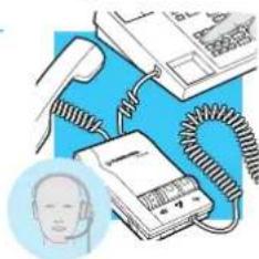
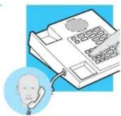
Making and Receiving Calls with a Handset
- Release the Headset /Handset switch (no colored indicator showing).
text_image
Diagram of a device with labeled parts and icons, showing a closed book with visible text and symbols.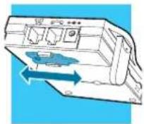
-
To access the Outgoing Volume Control, remove the panel on the left-hand side of the amplifier. The same panel houses the Telephone/Amplifier Compatibility Switch.
-
Use the phone handset as you normally would.
-
Use the screwdriver attached to the bottom of the amplifier to adjust the Outgoing Volume Control. Turn clockwise to make your voice louder to the caller. Turn counter-clockwise to make your voice quieter to the caller.
-
Replace the panel door and the screwdriver.
natural_image
Illustration of a telephone handset with a face icon, no text or symbols presentVISTA.engl.mech 9/16/02 5:12 PM Page 12

text_image
A maintenance and troubleshooting SECTION typ. serrations : .25" min. .375" min. .25 low force 4.0 max. 1 hand 2 hands 1-2" 3-5" .5" min. .875-1" opt. .03 R. 5° skirt 12 englishMAINTENANCE AND TROUBLESHOOTING
Maintenance Hints
Trouble Shooting Guide
PROBLEM
I DO NOT HEAR A DIAL TONE WHEN I TRY TO MAKE OR RECEIVE A PHONE CALL.
ITEMS TO CHECK
If you are using batteries, confirm that they are good and placed in the battery compartment correctly.
If you are using an AC Power Supply, confirm that it is plugged in and the power outlet is turned on.
Confirm that the Headset /Handset Selector switch is depressed (colored indicator showing).
Confirm that you have lifted the telephone handset out of the cradle.
Confirm that the telephone handset cable and the short curly pigtail to the telephone are connected to the correct jacks. (see "Installation")
Confirm that the Telephone/Amplifier Compatibility Switch is in the correct setting for your phone (see "Set the Telephone/Amplifier Compatibility Switch" on page 5). You may want to try moving the switch through all of the positions until you hear a clear dial tone. Experimenting with various switch settings will not harm the amplifier or your phone.
The Plantronics Help Desk is ready to assist you! Monday through Friday 8:00 AM to 5:00 PM PST 800 544-4660
MAINTENANCE AND TROUBLESHOOTING
Maintenance Hints
Trouble Shooting Guide
| PROBLEM | ITEMS TO CHECK |
| MY CALLERS SAY THAT THEY CAN'T HEAR ME AT ALL OR THEY CAN'T HEAR ME VERY WELL. | Make sure the microphone of your headset is positioned in front or near your mouth. If you are using a "noise-cancelling" headset, the position of the microphone is very important.You may need to adjust the "Outgoing Volume". See "Adjusting Headset Outgoing Volume" on page 10).Confirm that the Telephone/Amplifier Compatibility Switch is in the correct setting for your phone (see "Set the Telephone/Amplifier Compatibility Switch" on page 5). You may want to try moving the switch through all of the positions until your caller hears you clearly. Experimenting with various switch settings will not harm the amplifier or your telephone. |
| I GET A LOW PITCHED HUM IN MY HEADSET SPEAKER AND/OR MY CALLERS COMPLAIN THEY CAN HEAR HUM. | Try moving the Telephone/Amplifier Compatibility Switch through all of the positions until the hum disappears. Experimenting with various switch settings will not harm the amplifier or your telephone. |
| I HEAR THREE 'BEEPS' IN THE HEADSET. | If you are using batteries to power the Vista Amplifier, the three 'beeps' tell you that the batteries are low and need to be replaced.See "Install Batteries" on page 2. |
B
and accessories
text_image
protected buttons 93 D. 2.25 2.25 x 4" hole or 3.5" sq.hole 7.5 1.02 - S.M. L17 - AV M L31 - L.M. 32" 54" 80" 3 LB, max.F. L LB op! prefer to operofe push buttons by finger pods 90" 95" 110"english14
REPLACEMENT PARTS AND ACCESSORIES FOR VISIA
For information on accessories and spare parts, call Plantronics at 1-800-544-4660, or visit the Plantronics web site at www.plantronics.com
REPLACEMENT PARTS AND ACCESSORIES FOR VISTA
AC Power Supply
ITEM PART # AC Power Supply 26503-01
Telephone/Amplifier Compatibility Slide Switch Door
ITEM PART # Telephone/Amplifier 44015-01 Compatibility Slide Switch Door
Battery Door
ITEM PART # Battery Door 44014-01
Amplifier to Telephone Coil Cable
(male to male modular plugs) ITEM PART # Amplifier to Telephone 40974-01 Coil Cable
Amplifier to QD Coil Cable
(QD to male modular plug) ITEM PART # Amplifier to QD 26716-01 Coil Cable
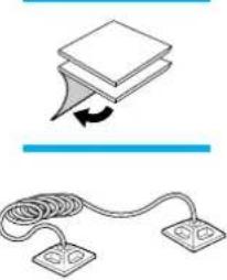
Velcro ^® Amplifier Attachment Kit
ITEM PART # Velcro Amplifier 17521-01 Attachment Kit
Amplifier Security Device
(attaches amplifier to desk.) ITEM PART # Amplifier Security 40696-01 Device
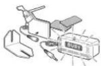
Plantronics Custom Cradle Mate
(holds handset "off-hook" and a flashing "BUSY" light indicates when headset is in use) ITEM PART # Plantronics Custom 40715-01 Cradle Mate
Cradle Mate only
(easy-to-use device that mechanically holds handset "off-hook") ITEM PART # Cradle Mate only 40714-01
natural_image
Simple line drawing of a stack of papers with an arrow indicating rotation, above a coiled cable and two separate circuit components (no text or symbols)
WARRANTY AND SERVICE
WARRANTY AND SERVICE
WARRANTY AND SERVICE
The following warranty and service information applies only to the U.S. and Canada. For information in other countries, please contact your local distributor.
To obtain in or out of warranty service, please prepay shipment and return the unit to the appropriate facility listed below:
IN THE UNITED STATES IN CANADA
Plantronics Service Center Plantronics Service Center
345 Encinal Street 1455 Pitfield Blvd.
Santa Cruz, CA 95060 Saint-Laurent, Quebec H4S 1G3
Tel. (800) 54 4- 4660 Tel. (800) 540-8363
(831) 458-7700 (514) 956-8363
Fax (800) 279-0162 Fax (514) 956-1825
Please use the original container, or pack the unit(s) in a sturdy carton with sufficient packing material to prevent damage. Include the following information:
- A proof-of-purchase indicating model number and date of purchase.
- Bill-to address
- Ship-to address
- Number and description of units shipped
- Name and telephone number of person to call, should contact be necessary
- Reason for return and description of the problem
Damage occurring during shipment is deemed the responsibility of the carrier, and claims should be made directly with the carrier.
FCC REGISTRATION INFORMATION
This equipment complies with Part 68 of the FCC rules. On the bottom of the modular adapter is a label that contains, among other information, the FCC registration number and finger equivalence number (REN) for this equipment. If requested, this information must be provided to the telephone company.
The telephone company may make changes in its facilities, equipment, operation or procedures that could affect the operation of the equipment. If this happens, the telephone company should provide you advance notice in order for you to make the necessary modifications to maintain uninterrupted services.
If you experience problems with your headset, please refer to the warranty section for information on warranty and repair service. If the problem is causing harm to the telephone network, the telephone company may request that you remove the equipment until the problem is resolved. In extreme cases, the telephone company may be forced to disconnect your service before notifying you of the problem.
The name Plantronics, the Plantronics logo and SoundGuard are registered trademarks of Plantronics, inc. Vista, Quick Disconnect, Call Clarity and SoundGuard Plus are trademarks of Plantronics, Inc. Velcro is a registered trademark of Velcro USA.
english18
english 19