
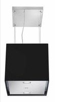
VESCM52BL - Range hood RANGEMASTER - Free user manual and instructions
Find the device manual for free VESCM52BL RANGEMASTER in PDF.


| Product Type | Range Hood |
| Brand | Rangemaster |
| Model | VESCM52BL |
| Color | Black |
| Width | 52 cm |
| Mounting Type | Under-cabinet / Wall-mounted |
| Extraction Type | Recirculating or Ducted (optional kit) |
| Number of Motors | 1 |
| Fan Speeds | 3 |
| Control Type | Push button |
| Lighting | 2 x LED lights |
| Filter Type | Aluminum grease filter |
| Noise Level (max) | 62 dB(A) |
| Max Extraction Rate | 320 m³/h |
| Energy Class | B |
| Power Supply | 220-240 V / 50 Hz |
| Power Consumption | 150 W |
| Weight | 8.5 kg |
| Dimensions (W x D x H) | 520 x 280 x 150 mm |
| Duct Diameter | 120 mm |
| Grease Filter Cleaning | Hand wash or dishwasher safe |
| Activated Carbon Filter | Optional for recirculation |
| Safety Features | Overheat protection, auto shut-off |
| Warranty | 2 years |
Frequently Asked Questions - VESCM52BL RANGEMASTER
User questions about VESCM52BL RANGEMASTER
0 question about this device. Answer the ones you know or ask your own.
Ask a new question about this device
Download the instructions for your Range hood in PDF format for free! Find your manual VESCM52BL - RANGEMASTER and take your electronic device back in hand. On this page are published all the documents necessary for the use of your device. VESCM52BL by RANGEMASTER.
USER MANUAL VESCM52BL RANGEMASTER

natural_image
Technical line drawing of a cylindrical container with four circular holes and vertical slots (no text or symbols)VESPER
Instructions Manual
www.rangemaster.co.uk
INDEX
EN
RECOMMENDATIONS AND SUGGESTIONS 3
CHARACTERISTICS 4
INSTALLATION....7
USE 18
MAINTENANCE 20
The Instructions for Use apply to several versions of this appliance. Accordingly, you may find descriptions of individual features that do not apply to your specific appliance.
INSTALLATION
- The manufacturer will not be held liable for any damages resulting from incorrect or improper installation.
- The minimum safety distance between the cooker top and the extractor hood is 650 mm (some models can be installed at a lower height, please refer to the paragraphs on working dimensions and installation).
- Check that the mains voltage corresponds to that indicated on the rating plate fixed to the inside of the hood.
- For Class I appliances, check that the domestic power supply guarantees adequate earthing. Connect the extractor to the exhaust flue through a pipe of minimum diameter 120 mm. The route of the flue must be as short as possible.
- Do not connect the extractor hood to exhaust ducts carrying combustion fumes (boilers, fireplaces, etc.).
- If the extractor is used in conjunction with non-electrical appliances (e.g. gas burning appliances), a sufficient degree of aeration must be guaranteed in the room in order to prevent the backflow of exhaust gas. The kitchen must have an opening communicating directly with the open air in order to guarantee the entry of clean air. When the cooker hood is used in conjunction with appliances supplied with energy other than electric, the negative pressure in the room must not exceed 0.04 mbar to prevent fumes being drawn back into the room by the cooker hood.
- In the event of damage to the power cable, it must be replaced by the manufacturer or by the technical service department, in order to prevent any risks.
- If the instructions for installation for the gas hob specify a greater distance specified above, this has to be taken into account. Regulations concerning the discharge of air have to be fulfilled.
USE
- The extractor hood has been designed exclusively for domestic use to eliminate kitchen smells.
- Never use the hood for purposes other than for which it has been designed.
- Never leave high naked flames under the hood when it is in operation.
- Adjust the flame intensity to direct it onto the bottom of the pan only, making sure that it does not engulf the sides.
- Deep fat fryers must be continuously monitored during use: overheated oil can burst into flames.
- Do not flambè under the range hood; risk of fire
- This appliance is not intended for use by persons (including children) with reduced physical, sensory or mental capabilities, or lack of experience and knowledge, unless they have been given supervision or instruction concerning use of the appliance by a person responsible for their safety.
- Children should be supervised to ensure that they do not play with the appliance.
- "CAUTION: Accessible parts may become hot when used with cooking appliances."
MAINTENANCE
- Switch off or unplug the appliance from the mains supply before carrying out any maintenance work.
- Clean and/or replace the Filters after the specified time period (Fire hazard).
- Clean the hood using a damp cloth and a neutral liquid detergent.
The symbol 📄 on the product or on its packaging indicates that this product may not be treated as household waste. Instead it shall be handed over to the applicable collection point for the recycling of electrical and electronic equipment. By ensuring this product is disposed of correctly, you will help prevent potential negative consequences for the environment and human health, which could otherwise be caused by inappropriate waste handling of this product. For more detailed information about recycling of this product, please contact your local city office, your household waste disposal service or the shop where you purchased the product,

natural_image
Illustration of a chemical experiment setup with a conical flask, smoke rising, and a control panel (no text or symbols)

natural_image
Illustration of a stove with steam rising and flames falling, crossed by a lightning bolt (no text or symbols)Components
| Ref. | Q.ty | Product | Components |
| 1 | 1 | Hood Canopy complete with: Controls, Light, Filters, Motor. | |
| 2 | 1 | Hood support Plate (with lamp holder) | |
| 3 | 1 | Power supply cable lock | |
| 4 | 1 | Cable raceway | |
| 5 | 1 | Glass or Panels the other material | |
| 14 | 1 | Pawl | |
| Ref. | Q.ty | Installation | Components |
| 11 | 4 | Wall plugs ø 10 | |
| 12h | 4 | Screws M5 x 70 | |
| 12c | 1 | Screws 2.9 x 9.5 | |
| 12d | 4 | Chrome plated glass fixing Pin/Screw | |
| 12g | 1 | Screw for pawl | |
| Q.ty | Documentation | ||
| 1 | Instruction | Manual | |

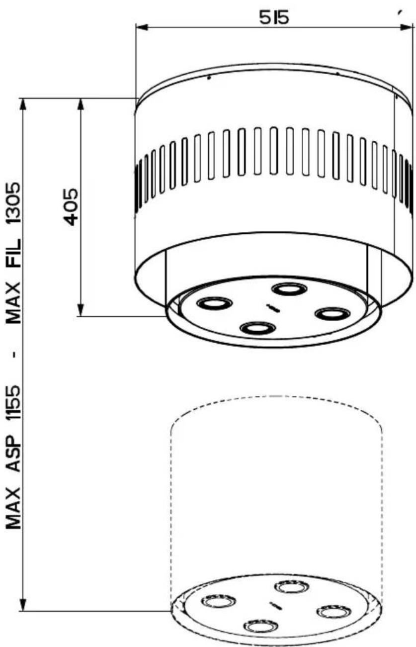
This hood is designed to be mounted on the ceiling/on a shelf, above a free-standing Hob (min. 650 mm), in:
- Ducting version: Evacuation to the outside.
• Recirculation version: Internal recirculation.
Sequence of operations - Installation
• Preparing for installation
- Drilling the Ceiling/Shelf and Fixing the support plate
- Connections
• Fitting the Hood canopy
- Functional Check
- Disposal of Packaging

natural_image
Illustration of a hand operating a drill bit with a screwdriver and tool nearby (no text or symbols)Fitting the Limiter pawl

natural_image
Technical line drawing of a mechanical flange with bolt holes and a highlighted circular component (no text or symbols)
natural_image
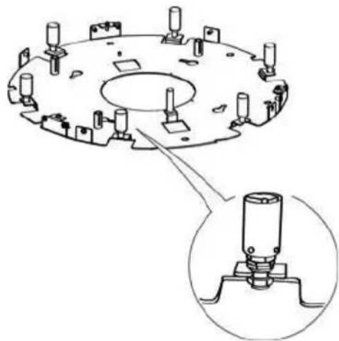
Diagram of a mechanical device with a central component and surrounding components, no text or symbols present.- Unfasten the 3 screw that join the parts of the Plate (of different shapes and/or sizes) using the wrench provided.
• Take the Pawl and fix it to the plate on the bracket in the position indicated in the figure, using the screw provided.
• Take the bulb holders and slot them onto the brackets provided, which can be seen by their fork-shaped ends.
Warning: the clamps used to fix the wires must not be cut.
- Tighten the Screw fixing the bulb holders to the bracket, in such a way as to hold the
natural_image
Technical line drawing of a mechanical component with mounting holes and a close-up inset showing a cylindrical assembly (no text or symbols)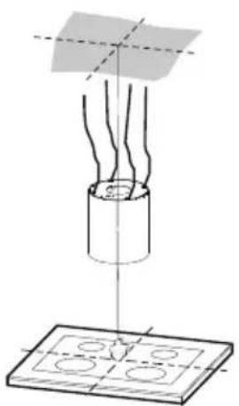
natural_image
Diagram of a mechanical assembly with a cylindrical component and a base plate, showing internal components and alignment lines (no text or symbols)
Ceiling/Shelf drilling and Plate Fixing
CEILING/SHELF DRILLING
- Use a plumb-line and mark the centre of the cooking hob on the Support Ceiling/Shelf.
- Rest the plate against the ceiling/shelf, taking care to keep the limit pawl that has just been fitted in a position facing the installer and the cooking hob (the limit pawl must not be confused with the other 4 used to fix the steel cables that move the Hood).
- Mark on the ceiling the centres of the holes in the plate.
- Drill the following points:
- Ceilings in solid concrete: As per concrete plugs used.
- Ceilings in hollow bricks with 20 mm resistance thickness: Drill a hole 10 mm (insert Plugs 11 supplied immediately).
- Ceilings with Wood Beams: As per Wood Screws used (not supplied).
- Wooden shelf, with a resistant thickness of 15 mm: drill a hole 7 mm.
- Feeding the electric supply cable: drill a hole 10 mm.
Warning: there will be two lines to be connected: a direct electric line for the hood power supply and another line with a switch for the lamp. This does not apply to Zoom model.
• Air Outlet (Ducting Version): according to the diameter of the connection to the external ducting pipe.
- Insert two screws, crossing them and leaving 4-5 mm from the ceiling:
• for solid concrete, concrete plugs, not provided.
- for hollow bricks with approx. 20 mm resistance thickness, screws 12h, provided.
• for wooden beams, wood screws, not provided.
• for wooden shelves, screws with washers and nuts, not provided.
FIXING THE PLATE
- Lift up the fixing plate, taking care to ensure that the limit pawl is positioned frontally.
- Fit the slots onto the two screws previously inserted in the ceiling, and turn until they are at the centre of the adjustment slot.
- Tighten the two screws completely and screw in the other two provided; before locking the screws completely it is possible to make adjustments by turning the piece, making sure that the screws do not come out of the adjustment slot.
- The unit must be securely fastened both due to the weight of the Hood and the stress caused by occasional sideways pressure on the Appliance when in position. Once the unit has been fixed, make sure that the plate is stable.
- In all cases where the Ceiling is not sufficiently strong at the point of suspension, the Installation technician must strengthen it with suitable plates and counterplates, anchored to structurally sound elements.


natural_image
Technical line drawing of a circular mechanical component with mounting holes and a central hole (no text or symbols)CONNECTING HOOD-PLATE CABLES
N.B. Before continuing with installation it is necessary to move the hood to a height of at least 650 mm from the cooker hob, using a support or the assistance of another person.
This is essential, as the hood cables must necessarily be connected to the plate fitted to the ceiling without the weight of the hood bearing on the structure.
- The cable fixing system is made up of 3 parts:
- Threaded Pawls (a) already mounted on the ceiling plate.
- Cable clamp screws (b) provided.
- Safety knobs (c) provided.

natural_image
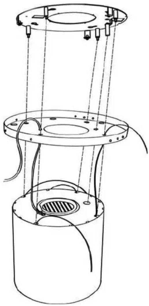
Abstract line drawing of a curved path with circular endpoints and small dots, no text or symbols present- Insert the cable raceway 4 in the opening on the plate cover and pass the hood power supply cable through it.

• Pass the cables connected to the hood canopy into the respective holes in the plate cover, after dismantling

- Attention to the direction of the plate fixed to the ceiling (the limit pawl on the plate fastened to the ceiling has a corresponding hole on the plate cover and on the hood canopy).

natural_image
Technical line drawing of a cylindrical mechanical assembly with mounting flanges and internal components (no text or symbols)- Insert the cables into the safety knobs (c) with the thread at the top.
- Insert the cables into the cable clamp screws (b)
- Pass the cables through the slots in the threaded pawls (a) and screw the cable locking screws (b) to the pawls themselves.


natural_image
Diagram of a mechanical device with a curved pipe and threaded base, showing motion direction (no text or symbols)
natural_image
Technical line drawing of a cylindrical mechanical device with vertical supports and internal components, no text or symbols present.- At this point we have all 4 cables connected to the plate
Bring the cables under tension by pushing them upwards so that they slide inside the cable clamp screw and slide out of the slot in the threaded pawl.
This is possible because the cable clamp screw has a system that, if mounted properly, allows the cables to slide inside it in one direction only, and prevents it from sliding in the other direction.
Attention, the cables all have the same length to facilitate the operation of the final level. The front left cable must not be slacker than the others.
- At this point it is possible to connect up the hood, and the lamp if there is one, to the power supply using the respective power cables.

- Close the plate cover using the 3 screws removed previously and the wrench provided
- At this point the Hood is suspended.
Connections
AIR OUTLET - DUCTING VERSION
To install the hood in the ducting version, please refer to the instructions provided in the ducting kit specific to the hood.
AIR OUTLET – RECIRCULATION VERSION
- Open the lighting unit by pulling on the notch provided.
- Remove the grease filter.
- Make sure that the Activated charcoal odour filter has been fitted.
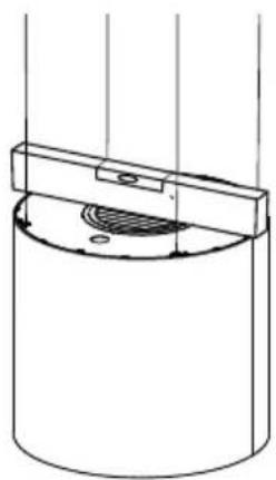
LEVELLING THE HOOD
- The hood mobile unit must be levelled to allow the movement to operate properly.
- The hood is levelled by adjusting the safety pawls.
natural_image
Simple line drawing of a cylindrical container with a side panel and internal structure (no text or symbols)• Rest a spirit level on the hood.
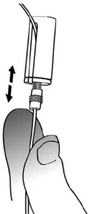
- When the safety knobs are pressed upwards, movement of the hood is “unlocked”. By inserting or extracting the cable from the cable clamp screw it is possible to make adjustments that allow the mobile hood body to be levelled.
- Once the hood has been set level, the safety knobs must be tightened again.
natural_image
Illustration of a hand holding a medical device with a vertical arrow indicating motion (no text or symbols present)Warning:
- Please check that all 4 cables are stretched.
- Please check that all 4 cables were not damaged during installation.
- It must be remembered that the minimum distance between the hood and the cooking hob must be 650mm.
- The mobile unit (hood canopy) must have a maximum stroke of 900 mm in case of recirculation version and in the case of the ducting kit of 750mm.
FIXING THE POWER SUPPLY CABLE
- Wind the power cable around its axis so that it forms a spiral from the mobile body to the plate in the ceiling.
- It is important to do this to prevent the wire come out from the hood body during the closing of the hood

natural_image
Technical line drawing of a mechanical component with a magnified inset showing a detail (no text or symbols)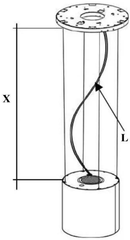
• Take the cable clamp 3 provided.
- Insert the Power cable in the Cable clamp 3 and screw it to the plate using one of the Screws 12c provided.
Finally, check that the power supply cable is properly locked, checking that when the mobile unit rises up towards the ceiling, it positions itself over the mobile unit and does not come out from the edge of the hood.
The length of the Power Cable “L” must be equal to the stroke “X” plus 50mm for the Recirculation Version and 200 mm for the Ducting Version.
$$ \mathrm{L} = \mathrm{X} + 5 0 \mathrm{mm} \text { Recirculation version } $$
$$ \mathrm{L} = \mathrm{X} + 2 0 0 \mathrm{mm} \text { Ducting version } $$
FITTING THE GLASS (OR OTHER MATERIAL)
• Take the lamps and insert them in the lamp holders.
- They do not have to be screwed in, but simply inserted all the way.
- Fix the glass (or other material) 5 to the plate using the fixing knobs 12d.

Electrical connection
- Connect the Hood to the Mains Power Supply, inserting a bipolar switch with a contact aperture of at least 3 mm.
- Open the lighting unit by pulling on the catch provided
- Remove the Filter, pushing it towards the back of the unit and at the same time pulling downward.
- Make sure that the Power cable has been properly inserted into the Suction fan socket
- Replace the Grease filter and then the lighting unit.

natural_image
Diagram showing a mechanical component with an inset close-up of a tool interacting with a bracket (no text or symbols present)Control panel

| Button | Function Display | |
| L Turns the lights On/Off. | - | |
| T1 | Hood DownPress for 2 seconds to raise the Hood.Press briefly to turn the Motor On/Off. | On/Off |
| Hood UpPress once: The Hood lowers.Press a second time: The Hood Stops.When the movement has been completed the motor turns on at Speed two. | Off/Off | |
Warning: The Hood controls only control the Hood functions. The Lighting unit has a completely separate power supply and a separate switch.
The electronic control system recognises and signals two types of fault.
| Led T1 | |
| Slow flashing | Current absorption threshold exceeded:If an overload condition occurs, the fault is signalled by LED T1 on the keyboard flashing once every 2 seconds. Check that nothing is blocking normal hood movements.The signal remains active until a new hood open/close command is given. |
| Rapid flashing | Hood opening safety microswitch tripped:If the safety microswitch trips, the fault is signalled by LED T1 on the keyboard flashing quickly (once every 250 ms). This means that the hood has passed the microswitch...... Call Technical Assistance!You can continue to use the hood's light and motor functions while this fault is active. Whenever the motor is on, LED T1 will continue to flash, indicating that the fault is still present. |
REMOTE CONTROL
The appliance can be controlled using a remote control powered by a 1.5 V carbon-zinc alkaline batteries of the standard LR03-AAA type (not included).
- Do not place the remote control near to heat sources.
- Used batteries must be disposed of in the proper manner.

natural_image
Diagram of a car interior showing two compartments with a central panel and directional arrow (no text or symbols)Control panel

natural_image
Black handheld electronic device with a circular knob (no text or symbols visible)| Button | Function | Display |
| Turns the Motor On/Off. - | ||
| Hood Closed:- Press the button briefly to start lowering the hood- It will stop when the button is pressed again.When the movement has been completed the motor will start at speed 2. | - | |
| Hood Open:- Press and hold for 2 seconds to activate raising of the hood, which stops when it reaches the stop.- Press (briefly) to stop the movement (before the stop is reached).- Press again briefly to turn the motor on/off.- Press and hold for 2 seconds to start raising of the hood.- If the motor is on, it will first stop the motor and then start the movement. | - | |
| - | Decreases the speed of the Motor. - | |
| + | Increases the speed of the Motor. - | |
| i | INTENSIVE- This can only be activated with the hood lowered and when the delay or 24h functions are not active.- Activates Intensive speed from any other speed.To disable it, simply press the same button again or turn the motor off.- Intensive speed is timed to run for 10 minutes. At the end of the 10 minutes the system will automatically return to the speed that was set before. | The led on the motor button (on the hood controls) will flash once a second. |
| Press briefly for the Delay Function:Can only be activated if the Intensive or 24h function is not active.Activates and deactivates total shutdown of the hood (motor+lights) after 30 minutes:To disable the Delay, simply press the button again or turn the motor off. | The led on the motor button (on the hood controls) will flash once every 0.5 seconds. | |
| Press and hold for 2 sec. for the 24H Function:Can only be activated if the Intensive or Delay function is not active.Activates and deactivates the 24H function for 10 minutes every hour, for 24 hours. After this time it is deactivated. | The led on the motor button (on the hood controls) will flash once every 2 seconds. | |
| Turns the Hood lights On/Off. |
Grease filter
The filter must be cleaned every 2 months of operation, or more frequently for particularly heavy usage, and can be washed in a dishwasher.
CLEANING METAL SELF- SUPPORTING GREASE FILTER
- Open the lighting unit by pulling on the noch.
- Remove the filter one by one pushing it towards the back side of the hood unit and simultaneously pulling downwards.
- Any kind of bending of the filter has to be avoided when washing it. Before fitting it again into the hood make sure that it is completely dry.
- When fitting the filter into the hood pay attention that they are mounted in correct position the handle facing outwards.
- Replace the lighting unit.
Activated Charcoal Filter (Recirculation Version)
This cannot be washed or regenerated, and must be changed approximately once every 4 months, or more frequently in the case of particularly intensive use.
CHANGING
- Open the light unit.
- Remove grease filter.
- Remove the saturated Activated Charcoal Filters, as indicated (A).
• Fit the new Filters, as indicated (B). - Fit the anti-grease filter and the Light Unit back into position.

natural_image
Hand holding a tablet device with a finger pointing to the screen (no text or symbols visible)
Lighting
LIGHT REPLACEMENT
20 W halogen light.
- Remove the snap-on lamp cover by levering it from under the metal ring, supporting it with one hand.
- Remove the halogen lamp from the lamp holder by pulling gently.
- Replace the lamp with a new one of the same type, making sure that you insert the two pins properly into the housings on the lamp holder.
- Replace the snap-on lamp cover.
natural_image
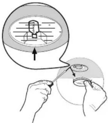
Illustration of hands using a tool to adjust a circular component, with no visible text or symbols.- Open the lighting unit by pulling on the notch provided.
- Apply the label, indicated the type of lighting, on the Hood as indicated in the figure (Rif.A).

Procedure to be used in case of malfunction on the movement
- Check that the fuse is properly inserted and that it has not burned out, for replacing the fuse open the lighting unit and unscrew the fuser holder and replace it with one having the same characteristics (Rif.B)
- Check that the hood canopy is fitted level (the use of a spirit level is recommended).
- Check that the four cables are all at the same tension. The front left cable must not be slacker than the others.
If even these operations do not solve the problem contact the Technical Assistance.
RANGEmaster
Clarence Street, Royal Leamington Spa,
Warwickshire, CV31 2AD, England.
Tel: +44 (0) 1926 457400 Fax: +44 (0) 1926 450526
E-mail: consumers@rangemaster.co.uk
www.rangemaster.co.uk
AGA RANGEMASTER GROUP PLC



- VESPER
- Instructions Manual
- INDEX
- INSTALLATION
- USE
- MAINTENANCE
- Sequence of operations - Installation
- Fitting the Limiter pawl
- Ceiling/Shelf drilling and Plate Fixing
- CEILING/SHELF DRILLING
- FIXING THE PLATE
- CONNECTING HOOD-PLATE CABLES
- Connections
- AIR OUTLET - DUCTING VERSION
- AIR OUTLET – RECIRCULATION VERSION
- LEVELLING THE HOOD
- Warning:
- FIXING THE POWER SUPPLY CABLE
- FITTING THE GLASS (OR OTHER MATERIAL)
- Electrical connection
- Control panel
- The electronic control system recognises and signals two types of fault.
- REMOTE CONTROL
- Grease filter
- CLEANING METAL SELF- SUPPORTING GREASE FILTER
- Activated Charcoal Filter (Recirculation Version)
- CHANGING
- Lighting
- LIGHT REPLACEMENT
- W halogen light.
- Procedure to be used in case of malfunction on the movement
- RANGEmaster
Brand : RANGEMASTER
Model : VESCM52BL
Category : Range hood