
CS-52553CB - Computer Case ANTEC - Free user manual and instructions
Find the device manual for free CS-52553CB ANTEC in PDF.


| Product Type | Computer Case (Mid Tower) |
| Brand | Antec |
| Model | CS-52553CB |
| Form Factor | Mid Tower |
| Motherboard Support | ATX, Micro ATX, Mini ITX |
| Dimensions (D x W x H) | 500 mm x 200 mm x 450 mm |
| Weight | 7.2 kg |
| Material | Steel, Plastic, Tempered Glass |
| Power Supply Included | No |
| Power Supply Mount | Bottom Mount |
| Front I/O Ports | 2x USB 3.0, 1x USB 2.0, Audio In/Out |
| Drive Bays | 2x 3.5", 2x 2.5" (internal) |
| Expansion Slots | 7 |
| Maximum GPU Length | 350 mm |
| Maximum CPU Cooler Height | 160 mm |
| Fan Support (Front) | 3x 120 mm or 2x 140 mm |
| Fan Support (Top) | 2x 120 mm or 2x 140 mm |
| Fan Support (Rear) | 1x 120 mm |
| Radiator Support (Front) | Up to 360 mm |
| Radiator Support (Top) | Up to 280 mm |
| Dust Filters | Bottom, Front, Top mesh |
| Side Panel | Tempered Glass (left side) |
| Cable Management Space | 20 mm behind motherboard tray |
| Clean & Maintain | Removable dust filters; wipe with dry cloth |
| Safety Features | Tempered glass panel, all edges rounded, sturdy construction |
| Spare Parts & Repairability | Standard screws, filters, fans available; tool-less drive bays |
Frequently Asked Questions - CS-52553CB ANTEC
User questions about CS-52553CB ANTEC
0 question about this device. Answer the ones you know or ask your own.
Ask a new question about this device
Download the instructions for your Computer Case in PDF format for free! Find your manual CS-52553CB - ANTEC and take your electronic device back in hand. On this page are published all the documents necessary for the use of your device. CS-52553CB by ANTEC.
USER MANUAL CS-52553CB ANTEC
Nine Hundred
User's Manual
At Antec, we continually refine and improve our products to ensure the highest quality. So it's possible that your new case may differ slightly from the descriptions in this manual. This isn't a problem; it's simply an improvement. As of the date of publication, all features, descriptions, and illustrations in this manual are correct.
Disclaimer
This manual is intended only as a guide for Antec's Computer Enclosures. For more comprehensive instructions on installing the motherboard and peripherals, please refer to the user's manuals which come with the components and drives.
Nine Hundred User's Manual
The Nine Hundred comes without a power supply. Make sure you choose a power supply that is compatible with and has long enough power harnesses to reach your motherboard and peripheral devices. We recommend our TruePower 2.0, Neo HE or Phantom power supplies for the latest ATX specification compliance, wide compatibility, and power savings capability.
Most ATX power supplies come with an on/off switch. Make sure you turn the switch to the ON (I) position before you boot up your computer for the first time. Normally, you won't need to switch to the OFF (O) position, since the power supply includes a soft on/off feature. This lets you turn your computer on and off by using the soft switch on your computer case. If your computer crashes and you can't shut it down using the soft switch, you can switch the main power to the OFF (O) position, to clear the fault, then reboot.
Attention:
Nine Hundred comes with a top storage tray. Antec does not recommend that users put any liquid-containing items (drinks, candles, coffee, perfume, etc.) in this area. Feel free to put your personal media player, digital camera, keys, coins, etc. in the top storage tray.
Setting Up
- Place the case upright on a flat, stable surface so that the rear panel (power supply and expansion slots) is facing you.
- Remove the thumbscrews from a side panel and open it by sliding it towards yourself. Place the thumbscrews carefully aside as they are NOT interchangeable with the HDD cage thumbscrews. Note: Don't use your fingernail to pry or lift the panels.

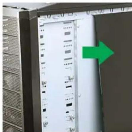
- Remove the thumbscrews from the other side panel and open it by sliding it towards yourself. Place the screws carefully aside. Inside the case is the power supply mount at the lower rear of the case and the 5.25" drive bay area with two HDD cages inside the bays. You will also find some wiring with marked connectors (USB, PWR etc.), an installed I/O panel and a toolbox containing more hardware (screws, brass standoffs, etc.)
Installing the Power Supply
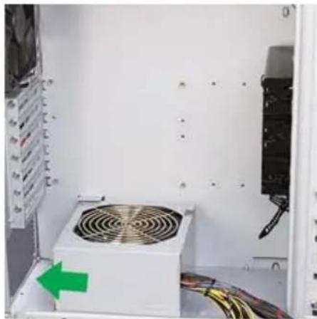
- With the case upright, place the power supply on the four silicone pads on the bottom of the case. Note: Power supplies with fans on the bottom of the power supply will need to be mounted so that the fan is facing the top of the case. Nine Hundred provides mounting holes for power supplies with standard mounting layouts to be installed upside up or upside down.
- Push the power supply to the back of the case and align the mounting holes.
- Attach the power supply to the case with the screws provided.
Installing the Motherboard
This manual does not cover CPU, RAM, or expansion card installation. Please consult your motherboard manual for specific mounting instructions and troubleshooting.
- Lay the case down, with the open side facing up. The drive cages and power supply mount should be visible.
- Make sure you have the correct I/O panel for your motherboard. If the panel provided with the case isn't suitable, please contact your motherboard manufacturer for the correct I/O panel.
- Line up your motherboard with the standoff holes, and remember which holes are lined up. Not all motherboards will match with all the provided holes; this is normal, and won't affect functionally. (In other words, there will likely be extra holes.)

- Remove your motherboard by lifting it up.
- Screw the brass standoffs into the threaded holes that line up with your motherboard. Do not over tighten the standoffs. Some standoffs may be pre-installed for your convenience.
- Place your motherboard on the brass standoffs.
- Screw in your motherboard to the standoffs with the provided Philips-head screws. Your motherboard is now installed.
Connecting the Power and LED
- Connect the Reset switch (labeled RESET SW) to your motherboard at the RST connector.
- Connect the Power LED (labeled POWER LED) connector to the PWR LED connector on the motherboard.
- Connect the Power Switch (labeled POWER SW) to the PWR connector on the motherboard.
- Connect the Hard Drive LED (labeled H.D.D. LED) to the HDD LED connector on the motherboard.
Connecting the USB Ports
Note: Please check your motherboard manual for your USB header pin layout and make sure it matches the attached table. If it does not match this Intel standard, please call Antec customer support at (800) 22ANTEC (North America) or at +31 (0) 10 462-2060 (Europe) to buy a USB adapter (SKU#30095). This adapter will allow you to connect the top USB to your motherboard on a pin-by-pin basis.
Motherboard Pin Layout
| Pin Signal Names Pin Signal Names | |||
| 1 | USB Power 1 | 2 | USB Power 2 |
| 3 | Negative Signal 1 | 4 | Negative Signal 2 |
| 5 | Positive Signal 1 | 6 | Positive Signal 2 |
| 7 | Ground 1 | 8 | Ground 2 |
| 9 | Key (No Connection) | 10 | Empty Pin |
Connecting the IEEE 1394 (FireWire®, i.Link®) Port
Note: Please check your motherboard manual for your IEEE 1394 header pin layout and make sure it matches the attached table. If you intend to connect the front FireWire port to an IEEE 1394 add-on card that comes with an external-type IEEE1394 connector, please call Antec customer service at (800) 22ANTEC (North America) or +31 (0) 10 462-2060 (Europe) to buy an adapter (SKU#30031). This adapter will allow you to connect the top IEEE 1394 port to the external-type connector.
Pin Assignment for Front Panel IEEE 1394 Connector
| Pin Signal Names Pin Signal Names | |||
| 1 TPA + 2 TPA- | |||
| 3 Ground 4 Ground | |||
| 5 TPB + 6 TPB- | |||
| 7 + 1 | 2V (Fused) 8 + 12V | (Fused) | |
| 9 Key | (No Pin) 10 Ground | ||
Connecting the Audio Ports
For a non-Intel standard audio connection, you will need to plug the 7 individual connectors onto the motherboard as follows.
Locate the internal audio connectors from your motherboard or sound card. Consult your motherboard or sound card manual for the pin-out positions.
- Microphone Signal Pin: Connect the MIC connector to this pin.
- Microphone Power: Connect the MIC-BIAS connector to this pin.
- Ground Pin: Connect the AUD GND connector to this pin.
- Front Right Speaker Out Pin: Connect the FPOUT-R connector to this pin.
- Front Left Speaker Out Pin: Connect the FPOUT-L connector to this pin.
- Rear Right Speaker Out Pin: Connect the RET-R connector to this pin.
- Rear Left Speaker Out Pin: Connect RET-L connector to this pin.
Flexi Drive Bay System
The Nine Hundred comes with nine 5.25" external drive bays at the front of the case. There are two HDD cages preinstalled inside the bottom six 5.25" bays. Each HDD cage occupies three consecutive 5.25" drive bays and can house three hard disk drives. For maximum flexibility you can mount the HDD cage anywhere within the external drive bays (you are not limited to the bottom six bays).
Possible Drive Bay combinations include but are not limited to:
External 3 x 5.25" + internal 6 x HDD - default
External 9 x 5.25" – by removing both HDD cages
External 6 x 5.25" + internal 3 x HDD - by removing one HDD cage
External 3 x 5.25" + internal 3 x HDD + VGA cooling duct - by adding the
Middle Fan to one of the HDD cages (see below)
External 5.25" Device Installation
Note: The HDD cages each occupy three consecutive drive bays, and will block installation of larger devices such as optical drives, so please plan ahead before installing your drives.
- Remove both side panels per the instructions in Setting Up.
- Remove the screws fastening the appropriate metal drive bay cover(s) to the sides of the case. Remove the cover(s).
- If necessary, please remove the HDD cage that is preinstalled in the bay.
- Slide the 5.25" device into the bay from the front of the case.
- Fasten the drive using the screws that came with your drive.
- Mount the other devices accordingly.
- Connect the appropriate connector(s) from the power supply to the device(s).
3.5" Hard Drive Installation
There are two HDD cages provided with the case. Each can store three hard disk drives.
- Remove both side panels per the instructions in Setting Up.
- Remove the thumbscrews fastening the HDD cage to the 5.25" drive bays, and set them carefully aside. Note: do not confuse the HDD cage thumbscrews with the side panel thumbscrews, as they are different.
- Slide the HDD cage forward out of the front of the case to remove it from the case.
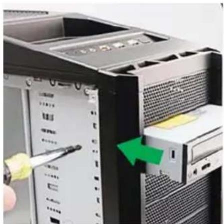

- Mount the hard drive into the drive cage and fasten it using the screws provided in the tool bag.
- Repeat the same procedure for the other HDD(s) as necessary.
- Slide the HDD cage back to the case and fasten the thumbscrews.
- Connect the appropriate connector(s) from the power supply to the device(s).
Note: There is a middle fan bracket pre-installed on one of the HDD cages. Remove the middle fan bracket from the HDD cage if you decide to mount your hard drives into this cage.

External 3.5" Drive Installation
In the toolbox you'll find a 3.5" to 5.25" drive bay adapter tray and an external 3.5" to 5.25" drive bay adapter cover.
- Remove both side panels per the instructions in Setting Up.
- Remove the drive bay cover from the drive bay you wish to install an external 3.5" drive into.
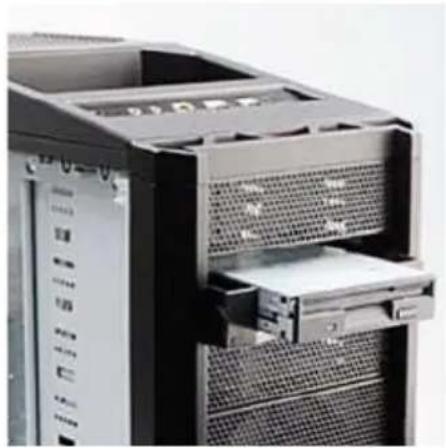
- Install your external 3.5" device into the tray.
- Slide the drive tray/device assembly into the bay. Screw the tray to the drive cage.

Cooling System
The Top 200mm TriCool™ fan:
Antec understands you desire the coolest gaming system, that's why the Nine Hundred comes with a 200mm TriCool™ fan. This fan has a three-speed switch that lets you choose the speed best suited to your needs. The default setting is Low.
The Front TriCool™ fans:
The Nine Hundred comes with two 120 x 25mm TriCool™ blue LED fans pre-installed in front of each HDD cage to cool the hard drives. These fans are installed so that air is blown into the case.
The Rear Exhaust TriCool™ Fan
There is a 120 x 25mm TriCool™ fan preinstalled at the rear of the case. The fan is installed so that air is blown out of the case.
200mm Fan Specifications:
Size: 200 x 30mm TriCool™ Fan
Rated Voltage: 12V DC
Operating Voltage: 10.8V ~ 13.2V
| Speed InputCurrent | Air Flow StaticPressure | AcousticalNoise | InputPower | |
| High800 RPM | 0.3A 3.80 m3 / min(134 CFM) | 0.69 mm-H2O(0.03 inch-H2O) | 30 dBA 3.6 W | |
| Medium600 RPM | 0.17A 3.07 m3 / min(108 CFM) | 0.40 mm-H2O(0.02 inch-H2O) | 27 dBA 2.04 W | |
| Low400 RPM | 0.08A 2.34 m3 / min(83 CFM) | 0.20 mm-H2O(0.01 inch-H2O) | 24 dBA 1.0 W |
120mm Fan Specifications:
Size: 120 x 25mm TriCool™ Fan
Rated Voltage: 12V DC
Operating Voltage: 10.2V ~ 13.8V
| Speed InputCurrent | Air Flow StaticPressure | AcousticalNoise | InputPower | ||
| High2000 RPM | 0.24A(Max.) | 2.24 m3 / min(79 CFM) | 2.54 mm-H2O(0.10 inch-H2O) | 30 dBA 2.9 W | |
| Medium1600 RPM | 0.2A 1.59 | m3 / min(56 CFM) | 1.53 mm-H2O(0.06 inch-H2O) | 28 dBA 2.4 W | |
| Low1200 RPM | 0.13A 1.1 | m3 / min(39 CFM) | 0.92 mm-H2O(0.04 inch-H2O) | 25 dBA 1.6 W | |
Note: These TriCool™ fans have a three-speed switch that lets you choose between quiet, performance, or maximum cooling.
Note: The minimum voltage to start a 120mm TriCool™ fan is 5V. We recommend that you set the fan speed to High if you choose to connect the fan(s) to a fan control device or to the Fan-Only connector found on some Antec power supplies. A fan control device regulates the fan speed by varying the voltage, which may start as low as 4.5V to 5V. Connecting a TriCool™ fan set on Medium or Low to a fan-control device may result in the fan not being able to start because the already lowered voltage from the fan control device will be further reduced by the TriCool™ circuitry below 5V.
The Optional Fans
There are two optional 120mm fan mounts – the side fan (on the left side panel) and the middle fan (at the rear end of the HDD cage). We recommend using Antec 120mm TriCool™ fans and setting the speed to Low. These two fans should be installed so that the air is blowing into the case.
The Side Fan — the Side fan is there to enhance VGA cooling. Just drop a fan into the bracket on the side panel so that air is blowing into the case.
The Middle Fan — the middle fan is designed to cool the CPU, VGA card or the power supply if you choose to use a fanless power supply depending on which drive bays you install the HDD cage into. You can use the middle fan on whichever drive cage you do NOT install hard drives in. This design is especially useful in cooling dual VGA card implementations.
- In the toolbox you'll find a black plastic fan mount. Place a 120mm fan in this fan mount.
- Run the power (and control switch if using a TriCool™ fan) through the cable guide that runs along the fan mount.
- Clip the fan mount/fan assembly onto the back of the HDD cage that you do not have HDD's mounted in.
- Connect the fan to the power supply.
Antec, Inc.
47900 Fremont Blvd.
Fremont, CA 94538
USA
tel: 510-770-1200
fax: 510-770-1288
Antec Europe B.V.
Sydneystraat 33
3047 BP Rotterdam
The Netherlands
tel: +31 (0) 10 462-2060
fax: +31 (0) 10 437-1752
Customer Support:
US & Canada
1-800-22ANTEC
customersupport@antec.com
Europe
+31 (0) 10 462-2060
europe.techsupport@antec.com
www.antec.com


- NINE HUNDRED
- USER'S MANUAL
- DISCLAIMER
- NINE HUNDRED USER'S MANUAL
- ATTENTION
- SETTING UP
- INSTALLING THE POWER SUPPLY
- INSTALLING THE MOTHERBOARD
- CONNECTING THE POWER AND LED
- CONNECTING THE USB PORTS
- CONNECTING THE IEEE 1394 (FIREWIRE®, I.LINK®) PORT
- CONNECTING THE AUDIO PORTS
- FLEXI DRIVE BAY SYSTEM
- EXTERNAL 5.25" DEVICE INSTALLATION
- 3.5" HARD DRIVE INSTALLATION
- EXTERNAL 3.5" DRIVE INSTALLATION
- COOLING SYSTEM
- THE TOP 200MM TRICOOL™ FAN
- THE FRONT TRICOOL™ FANS
- THE REAR EXHAUST TRICOOL™ FAN
- 200MM FAN SPECIFICATIONS
- 120MM FAN SPECIFICATIONS
- THE OPTIONAL FANS
Brand : ANTEC
Model : CS-52553CB
Category : Computer Case