
ATDF30 - Computer Case ANTEC - Free user manual and instructions
Find the device manual for free ATDF30 ANTEC in PDF.


| Product Type | Mid-Tower Computer Case |
| Motherboard Support | ATX, Micro-ATX, Mini-ITX |
| Dimensions (H x W x D) | 445 x 200 x 445 mm (17.5 x 7.9 x 17.5 in) |
| Weight | 6.5 kg (14.3 lbs) |
| Material | Steel and Plastic |
| Color | Black |
| Expansion Slots | 7 |
| Drive Bays - 3.5" | 2 |
| Drive Bays - 2.5" | 2 |
| Front Panel Ports | 2x USB 3.0, 1x Audio In/Out |
| Fan Support - Front | 3x 120mm or 2x 140mm (Optional) |
| Fan Support - Rear | 1x 120mm (Pre-installed) |
| Fan Support - Top | 2x 120mm / 2x 140mm (Optional) |
| Radiator Support - Front | Up to 280mm |
| Radiator Support - Rear | 120mm |
| Radiator Support - Top | Up to 240mm |
| PSU Support | Bottom-mounted, ATX PS2 (Optional) |
| Maximum GPU Length | 360 mm |
| Maximum CPU Cooler Height | 160 mm |
| Dust Filters | Front, Top, Bottom |
| Cleaning | Use a soft cloth or compressed air. Remove dust filters and rinse with water; dry thoroughly before reinstallation. |
| Safety | Ensure case is on a stable surface. Keep away from liquids. Do not block ventilation. |
| Repairability | Screws and standoffs are standard size. Power supply, fans, and drives are user-replaceable. |
Frequently Asked Questions - ATDF30 ANTEC
User questions about ATDF30 ANTEC
0 question about this device. Answer the ones you know or ask your own.
Ask a new question about this device
Download the instructions for your Computer Case in PDF format for free! Find your manual ATDF30 - ANTEC and take your electronic device back in hand. On this page are published all the documents necessary for the use of your device. ATDF30 by ANTEC.
USER MANUAL ATDF30 ANTEC
natural_image
Exterior view of a black server tower with visible CPU socket and heat sink (no text or symbols)DF-30 DARKFLEET

THE ADVANCED GAMING FORCE
USER MANUAL
DF-30 USER'S MANUAL
Congratulations on your purchase of the Antec Dark Fleet DF-30.
Meet the swifter, lighter Dark Fleet enclosure with the heavyweight feature set: the Dark Fleet DF-30. Up front sit two Fleet-Release™ access doors with tool-free washable fan filters, allowing rapid access to a massive array of drive bays – enough room for 11 total drives. Each Fleet-Release™ door comes standard with a variable-speed black 120 mm blue LED fan with stepless knob controls allowing precise tuning of your build's cooling/noise balance. Two built-in SATA bays – one 2.5" SSD mount on the interior, and a special external top hot-swap 2.5" SATA (SSD) bay – provide fast, smoothly integrated data transfer capability that fits right into the case. And since the Fleet-Release™ system is modular and features tool-free removable filters, maintaining and reconfiguring your build is a cinch. With dark industrial style and swiftly maintainable air-cooling design, the DF-30 is the lighter Dark Fleet enclosure that packs full-size power into a stylish, convenient mid-size package.
The DF-30 comes without a power supply. Make sure you choose a power supply that is compatible with your computer components and has a long enough power harness to reach your motherboard and peripheral devices. We recommend our High Current, Signature Series, TruePower Quattro or TruePower New power supplies for the latest ATX specification compliance, broad compatibility, and power savings capability.
At Antec, we continually refine and improve our products to ensure the highest quality. As such, your new case may differ slightly from the description in this manual. This isn't a problem; it's simply an improvement. As of the date of publication, all features, descriptions, and illustrations in this manual are correct.
Disclaimer
This manual is intended only as a guide for Antec's computer enclosures. For more comprehensive instructions on installing the motherboard and peripherals, please refer to the user's manuals that come with those components.
TABLE OF CONTENTS
SECTION 1: INTRODUCTION
1.1 Getting to know your case.... 5
1.2 Case specifications.... 6
1.3 Before you begin....7
1.4 Locating and positioning your computer.... 8
SECTION 2: HARDWARE INSTALLATION
2.1 Setting up.... 10
2.2 Motherboard installation.... 12
2.3 Standard ATX power supply installation.... 14
2.4 Cable management.... 15
2.5 Internal 3.5" device installation.... 16
2.6 External 3.5" device installation.... 18
2.7 Using the top 2.5" hot-swap bay.... 19
2.8 External 5.25" device installation.... 20
2.9 Internal 2.5" device installation.... 21
SECTION 3: FRONT I/O PORTS
3.1 USB 2.0....23
3.2 AC'97 / HD audio ports.... 23
3.3 Power switch / reset switch / hard disk drive LED connectors.... 24
3.4 Rewiring motherboard header connections.... 24
SECTION 4: COOLING SYSTEM
4.1 Included fans.... 26
4.2 Top 140 mm blue LED fan.... 27
4.3 Front 120 mm blue LED fans 27
4.4 Rear exhaust 120 mm TwoCool™ fans.... 28
4.5 Optional fans.... 28
4.6 Washable air filters.... 29
SECTION 1
INTRODUCTION
1.1

GETTING/TO/KNOW/YOUR/CASE

Drive bays
Hardware mounts
1 5.25" drive bays
2 3.5" drive bays
3 2.5" internal SSD bay
4 2.5" external hot-swap
8 Motherboard standoffs (pre-installed)
9 Power supply mounts
10 Front I/O ports
Cooling
5 140 mm top TwoCool™ fan
6 120 mm rear TwoCool™ fan
7 Fleet-Release access door modules w/front variable-speed 120 mm blue LED fans

| CASE TYPE | Mid Tower |
| COLOR | Matte black |
| DIMENSIONS | 19.1" (H) x 7.8" (W) x 19.1" (D)485 mm (H) x 198 mm (W) x 486 mm (D) |
| WEIGHT | 15.1 lbs / 6.9 kg |
| COOLING | 1 x top 140 mm TwoCoolTM fan1 x rear white 120 mm TwoCoolTM black-bladed fans with blue LED2 x front variable-speed 120 mm black -bladed LED fans with blue LED1 x side 120 mm fan for graphics cards (optional) |
| DRIVE BAYS | 6 x internal 3.5"3 x external 5.25"1 x top external 2.5" hot swap SATA drive bay1 x internal bottom-mounted 2.5" SSD bay |
| EXPANSION SLOTS | 7 |
| MOTHERBOARD SIZE | Mini-ITX, microATX, Standard ATX |
| FRONT I/O PANEL | 2 x USB 2.0AC'97 / HD Audio In and Out |
1.3
BEFORE/YOU/BEGIN/
In order to ensure that your building experience with the Dark Fleet DF-30 will be a positive one, please take note of the following:
- While working inside your Dark Fleet DF-30, keep your case on a flat, stable surface. Make sure your build area is clean, well-lit, and free of dust.
- Antec cases feature rounded edges that minimize the occurrence of hand injuries. Nonetheless, exercise caution and control when handling case interiors. We strongly recommend taking the appropriate time and care when working inside the case. Avoid hurried or careless motions. Please use reasonable precaution.
- Handle components and cards with care. Do not touch the components or contacts on a card. Hold a card by its edges. Hold a component such as a processor by its edges, never by its pins.
- To avoid electrostatic discharge, ground yourself periodically by touching an unpainted metal surface (such as a connector or screw on the back of this computer) or by using a wrist grounding strap.
- Before you connect a cable, ensure that both connectors are correctly aligned and oriented. Bent pins can be difficult to fix and may require replacement of the entire connector.
- This manual is not designed to cover CPU, RAM, or expansion card installation. Please consult your motherboard manual for specific mounting instructions and troubleshooting. Before proceeding, check the manual for your CPU cooler to find out if there are steps you must take before installing the motherboard.
- Do not sit on your case. Although it is constructed of heavy-duty steel and internally reinforced, it is not designed to support the weight of an adult, and may buckle.
- Remember to use the right tools for each task. Do not use improvised screwdrivers like coins, nails or knife blades as they may result in damage to screw threads or even injury. Do not use your fingernails to separate edges or lift the sides of the case, as paint chipping or injury may occur.

LOCATING/AND/POSITIONING/YOUR/COMPUTER/
Your DF-30 has backwards- and top-facing exhaust fans, as well as front-mounted intake fans and one side-mounted front air intake. For optimum performance, we recommend leaving the front air intakes unobstructed.
When open, the DF-30's Fleet-Release™ doors take up an additional 15.5 cm of space in the front. Since loading and unloading the DF-30's internal Fleet-Swap™ SATA bays through the doors will require opening and closing them, you may wish to leave space in front of the computer open for this purpose.
The DF-30 can operate resting sideways as well as vertically. Do not rest the DF-30 upside down (with the case feet up in the air), as this will impede operation of optical drives.

The DF-30 comes with a top 2.5" Hot Swap drive bay. While it's in a handy location, we do not recommend that users put any liquid-containing items (drinks, ice cream, coffee, perfume, etc.) on the drive bay. It was not designed for storage purposes.
SECTION 2
HARDWARE
INSTALLATION
2.1
S
ETTING/UP/
Put the case upright on a flat, stable surface so that the rear panel (power supply and expansion slots) is facing you. To remove the left and right side panels, remove these thumbscrews:

natural_image
Back view of a black desktop computer tower showing internal components including fan, drive, and ventilation slots (no text or symbols visible)Note: Place the panel thumbscrews aside carefully and remember where they are – they look very similar to the HDD cage thumbscrews, but they are NOT interchangeable.
Now rest your case with the left side up. Here's what we'll be working with first:

A - Power supply mounts
B - 5.25" drive bay area
C - 3.5" drive bay area
D - Front panel wiring
E - I/O panel
Note: Do not use your fingernails to pry or lift the panels. Damage to the panels or injury to your fingernails may result.
Note: This manual is not designed to cover CPU, RAM, or expansion card installation. Please consult your motherboard manual for specific mounting instructions and troubleshooting.
2.2

OTHERBOARD/INSTALLATION
Before proceeding:
- Check the manual for your CPU cooler to find out if there are steps you must do before installing the motherboard
- Make sure you have the correct I/O panel for your motherboard. If the panel provided with the case isn't suitable, please contact your motherboard manufacturer for the correct I/O panel.

natural_image
Internal view of an electronic device chassis showing ports, connectors, and a central display (no visible text or symbols)Make sure you have the correct I/O panel. This mismatched I/O panel can cause difficulties down the road.
- Lay the case down, with the open side facing up. The drive cages should be visible on the right side of the case, with the power supply in the upper left.
- Now insert your motherboard, aligning your motherboard with the standoff holes and remember which holes are lined up.
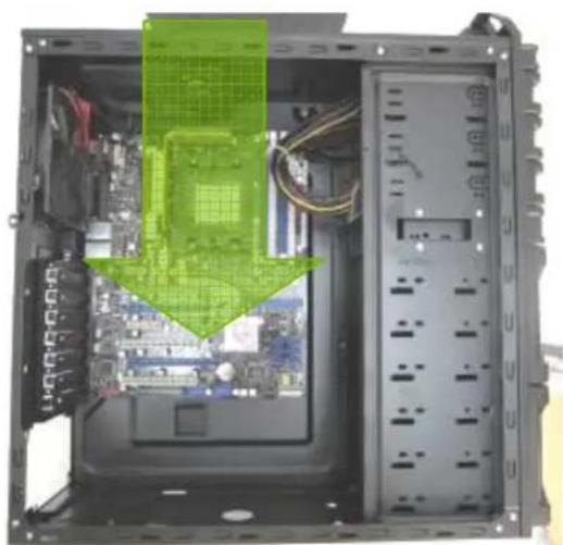
natural_image
Interior view of a computer tower case showing CPU socket, motherboard, and monitor (no visible text or labels)Installing the motherboard, step 2. Note that not all motherboards will match with all the provided holes; this is normal and won't affect functionality.
- Now remove your motherboard by lifting it up.

natural_image
Interior view of a computer tower case showing CPU socket, motherboard, and drive unit (no text or symbols visible)Lift your motherboard out to install the standoffs.
-
Install standoffs as needed and put the motherboard back in.
-
Screw in your motherboard to the standoffs with the provided Phillips-head screws.
Caution: Make sure to remove any unused motherboard standoffs. They may come into contact with the back of the motherboard and may electrify your case exterior if left connected.
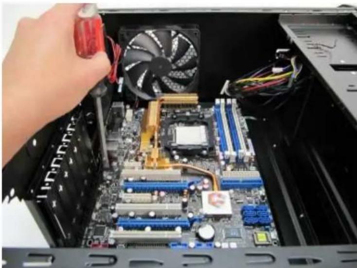
natural_image
Interior view of a computer tower with CPU socket, motherboard, and CPU fan (no visible text or labels)Step 5: Screwing in the motherboard after standoffs are installed
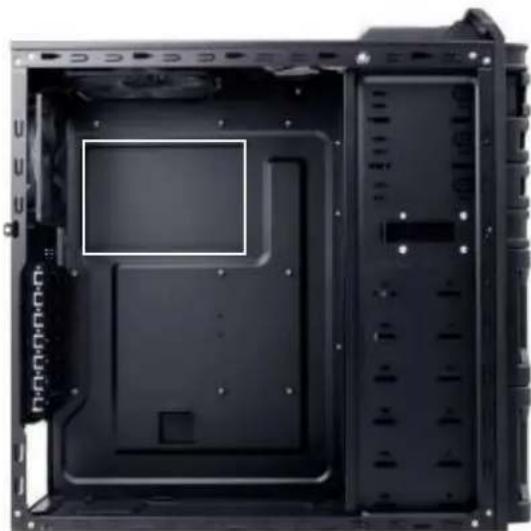
natural_image
Interior view of a black computer tower case showing internal compartments and mounting holes (no text or symbols visible)Note: The DF-30 comes with a CPU cutout on the motherboard tray, which will allow you to change your CPU heatsink without removing the motherboard.
2.3///// STANDARD/ATX/POWER/SUPPLY/INSTALLATION/
The DF-30 can accommodate a standard-size ATX power supply.
- With the case upright, place the power supply on the bottom of the case.

natural_image
Hand placing a green 3D grid component into a black CPU socket (no text or symbols visible)PSU resting on the standard PSU mount.
-
Push the power supply to the back of the case and align the mounting holes.
-
Attach the power supply to the case with the screws provided.

natural_image
Internal view of a computer power supply unit showing circuit board, connectors, and socket (no text or symbols visible)Use these screws to secure your power supply to the case.
Note: Power supplies with fans on the bottom of the power supply will need to be mounted so that the fan is facing the top of the case. The DF-30 provides mounting holes for power supplies with standard mounting layouts to be installed right side up or upside down.
2.4 CABLE/MANAGEMENT
There is a cable management compartment behind the 3.5" drive cage. You can tuck or route excess cables in this compartment.
- Locate the cable management compartment with cable ties located behind the walls of the 3.5" drive cage.
- Tuck or route your excess cables to the compartment. This will keep the cables from interfering with airflow in your case and help with cooling.
- Use the cable ties provided to hold them in place.
2.5

INTERNAL 3.5" DEVICE INSTALLATION
The DF-30 includes two Fleet-Release™ access doors. With the front bezel facing you, they are located by default on the bottom nine drive bay slots (each door covers three drive bays).
- Open the Fleet-Release ^TM access door.

natural_image
Close-up of a black server rack with a green grid overlay and a hand pointing to it (no visible text or symbols)Opening the Fleet-Release ^TM access door by gently pressing the left side to release it, and then swing it open.
- Insert your 3.5" device into the 3.5" drive cage from the front of the case. You will feel resistance from prestabs on either side of the drive cage which will create friction against the drive. Push gently until the drive's mounting holes align with the screw holes in the cage.

natural_image
Interior view of a black desktop computer tower case showing internal components and a green arrow pointing to a specific area (no text or symbols visible)Installing a 3.5" internal device
- Fasten the device in place with the provided screws on both side of the drive cage.

natural_image
Close-up of two black plastic electronic components with circular features and internal compartments (no text or symbols visible)Make sure to install screws on the left side... ...as well as the right side.
-
Mount any other 3.5" HDD devices accordingly.
-
Connect the appropriate power and data cables to the device(s), using cable routing as desired.
-
Close the Fleet-ReleaseTM access door.
There is one external 3.5" drive bay under the 5.25" drive bays.

natural_image
Close-up of a hand pressing down on a black CPU socket cover (no text or symbols visible)Remove this drive bay cover.
- Carefully remove the 3.5" drive bay cover from the bezel. Load the drives from the front, lining them up to the front of the drive cage.

natural_image
Close-up of a computer tower with a highlighted CPU fan component, showing no text or symbols on the fan or background.Insert your drive as shown.
-
With one hand supporting the drive, fasten the drive with the screws provided.
-
Find a small 4-pin white connector on the power supply and connect it to the male 4-pin connector on the floppy drive.
2.7

USING THE TOP 2.5" HOT-SWAP BAY
The DF-30's top 2.5" hard drive bay is hot-swap capable. To use the hot-swap feature, ensure that your motherboard is configured for hot-swap. Make sure to install all related drivers that come with your motherboard and turn on the AHCI function in the BIOS to activate the hot swap feature.

natural_image
Hand inserting a smartphone into an open battery pack with green circuit lines (no text or symbols visible)Using the top 2.5" hot-swap drive bay
A. LOADING:
- Align your SATA HDD with the drive bay with the connector facing the case.
- Push the HDD all the way into the bay until it locks into position.
B. UNLOADING:
- Ensure that your HDD is not in use.
- Carefully pull the HDD out of the hot-swap drive bay.
2.8

EXTERNAL 5.25" DEVICE INSTALLATION
There are three externally accessible 5.25" drive bays. Before you begin, remove both side panels.
- First, remove the drive bay faceplate and metal cover plate as shown below.

natural_image
Close-up of a hand inserting a black plastic component into a black plastic housing (no text or symbols visible)The plastic drive bay faceplate should pop free. A screwdriver may be needed to remove the metal cover plate.
- Slide your 5.25" device into the bay from the front of the case.
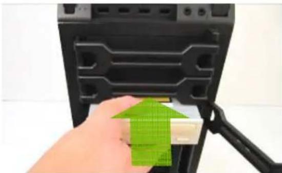
natural_image
Hand inserting a green 3D grid into a black server rack (no text or symbols visible)5.25" device installation
- Secure the drive into position in the drive bay using the provided screws on each side of the drive.
- Mount any other 5.25" devices accordingly.
- Connect the appropriate power and data cables to your device(s).
- Replace both side panels.
2.9

INTERNAL 2.5" DEVICE INSTALLATION
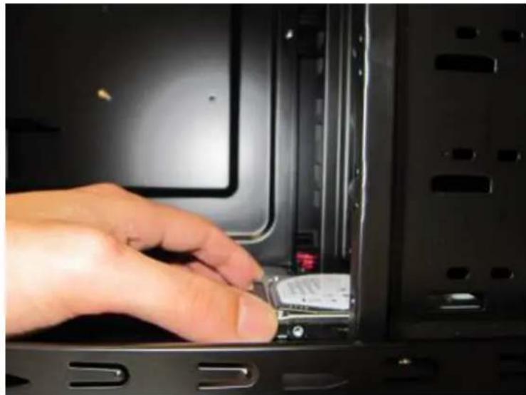
There is a 2.5" device mounting location located at the bottom of the case. To use this mounting location:
- Locate the bay at the bottom of the case.
natural_image
Hand inserting a small electronic device into a computer tower case (no visible text or symbols)The 2.5" mounting location
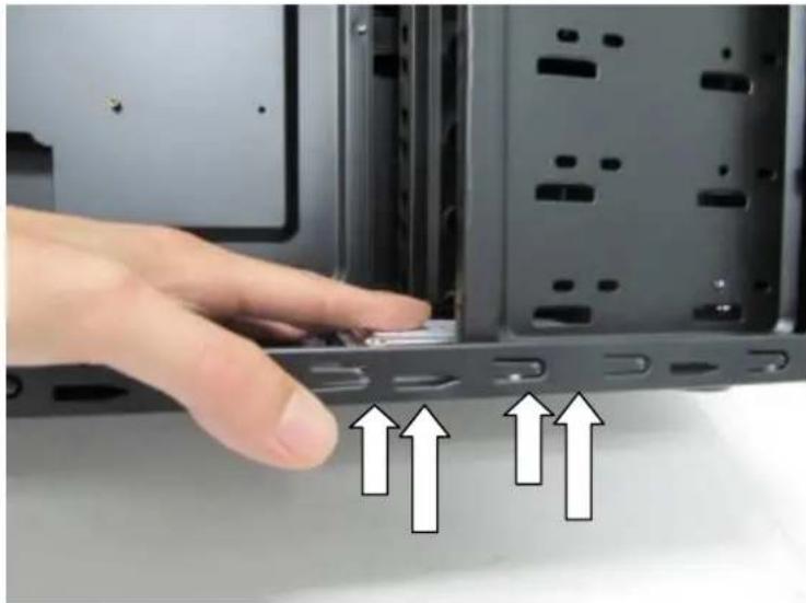
- Using the screws provided, secure your 2.5" device.
natural_image
Hand pressing a button on a computer tower panel, with three upward arrows indicating motion (no text or symbols present)Secure your 2.5" device from the bottom.
SECTION 3
FRONT I/O
PORTS
3.1

USB 2.0
Connect the front I/O panel USB cable to the USB header pin on your motherboard. Check your motherboard user's manual to ensure that it matches the table below:

| Pin | Signal Names | Pin | Signal Names |
| 1 | USB Power 1 | 2 | USB Power 2 |
| 3 | Negative Signal 1 | 4 | Negative Signal 2 |
| 5 | Positive Signal 1 | 6 | Positive Signal 2 |
| 7 | Ground 1 | 8 | Ground 2 |
| 9 | Key (No Connection) | 10 | Empty Pin |
3.2

AC'97 / HD AUDIO PORTS
There is an Intel® standard 10-pin AC'97 connector and an Intel® 10-pin HDA (High Definition Audio) connector linked to the front panel of the case.

| Pin | Signal Names (HDA) | Pin | Signal Names (AC'97) |
| 1 | MIC2 L | 1 | MIC In |
| 2 | AGND | 2 | GND |
| 3 | MIC2 R | 3 | MIC Power |
| 4 | AVCC | 4 | NC |
| 5 | FRO-R | 5 | Line Out (R) |
| 6 | MIC2_JD | 6 | Line Out (R) |
| 7 | F_IO_SEN | 7 | NC |
| 8 | Key (no pin) | 8 | Key (no pin) |
| 9 | FRO-L | 9 | Line Out (L) |
| 10 | LINE2_JD | 10 | Line Out (L) |
You can connect either the AC'97 or the HDA connector, depending on your motherboard. Locate the internal audio connectors from your motherboard or sound card and connect the corresponding audio cable. Consult your motherboard or sound card manual for the pin-out positions. Even if your system supports both standards, only use one connector.
3.3
POWER SWITCH / RESET SWITCH / HARD DISK DRIVE LED CONNECTORS
Connected to your front panel are LED and switch leads for power, reset, and HDD LED activity. Attach these to the corresponding connectors on your motherboard. Consult your motherboard manual for specific pin header locations. For LEDs, colored wires are positive (+). White or black wires are negative (−). If the LED does not light up when the system is powered on, try reversing the connection. For more information on connecting LEDs to your motherboard, see your motherboard user's manual.

Front Panel switch leads
Note: Polarity (positive and negative) does not matter for switches.
3.4
REWIRING MOTHERBOARD HEADER CONNECTIONS
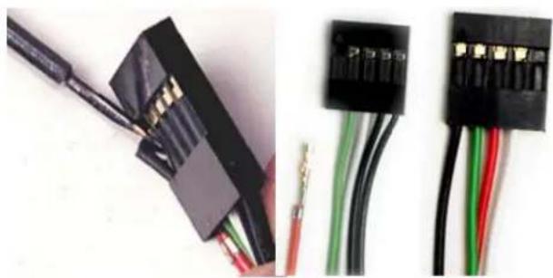
There may come a time when you need to reconfigure the pin-out of a motherboard header connector. Examples could be for your USB header, audio input header, or some other front panel connector such as the Power Button connector.
Before performing any work, please refer to your motherboard user's manual or your motherboard manufacturer's website to confirm the pin-out needed for your connector. We strongly recommend making a notated drawing before beginning work so that you can recover if your work gets disturbed.
natural_image
Close-up of two black electronic connectors with wires and gold contacts, no visible text or symbolsFront panel headers
-
Determine which wires you need to remove in order to rewire your plug to match the USB pin-outs on your motherboard (refer to your motherboard user's manual). Working on one connector at a time, use a very small flathead screwdriver or similar tool to lift up on the black tab located beside the gold posts (squares). This will allow you to easily slide out the pins from the USB plug.
-
Working carefully so as not to damage the wires, connectors, or pins, slowly remove the pin from the connector. Repeat these steps for each wire you need to change.
-
Working carefully so as not to damage the wires, connectors or pins, slowly reinsert the pin into the correct slot of the connector then snap closed the black tab that was lifted in step 1. Repeat these steps for each wire you need to change.
SECTION 4
COOLING
SYSTEM

Standard fans on the DF-30:
A - 1 x 120 mm rear TwoCool™ LED fan
B - 1 x 140 mm top TwoCool™ fan
C - 2 x Fleet-Release access door modules w/front variable-speed 120 mm blue LED fans

natural_image
Close-up of a black computer drive rear panel showing two Ethernet ports and a hexagonal mesh chamber (no text or symbols visible)Rear fan control panel
4.2
TOP 140 MM TwoCool™ FAN
The DF-30 comes with one 140mm TwoCool™ LED fan. This fan has a two-speed switch that lets you choose the speed best suited to your need and a switch to turn on or off the LED. These switches are located at the rear of the case. The default fan speed setting is Low.
140 MM FAN SPECIFICATIONS:
Size: 140 x 25 mm two-speed fan
Rated Voltage: 12V DC
Operating Voltage: 10.8V \~ 13.2 V
| Speed | Input Current | Air Flow Static Pressure | Noise | Input Power | |
| High 1200RPM | 0.3A | 1.7 m^3/ (58.9 CFM) | 0.8 mm- H_2O (0.03inch- H_2O ) | 26 dBA 3.6 W | |
| Low 800RPM | 0.2A | 0.95 m^3/ (33.6 CFM) | 0.28 mm- H_2O (0.01inch- H_2O ) | 21.8 dBA | 2.4 W |
4.3
FRONT 120 MM BLUE LED FANS
The DF-30 comes with two white 120 x 25 mm white LED fans which are pre-installed in front of each Fleet-Release™ access door to cool the hard drives. These fans are installed so that air will be blown into the case. Each fan comes with a speed control knob at the front of the faceplate. Turn the knob clockwise to increase the speed. The lowest speed is 1200 rpm while the highest speed is 2000 rpm.
120 MM BLUE LED FAN SPECIFICATIONS:
Size: 120 x 25 mm speed control fan
Rated Voltage: 12V DC
Operating Voltage: 10.8V \~ 13.2 V
| Speed | Input Current | Air Flow Static Pressure | Noise | Input Power | |
| Highest 2000RPM | 0.3A | 1.89m3 / min (66.60 CFM) | 2.55 mm-H2O (0.1inch-H2O) | 34.5 dBA | 3.6 W |
| Lowest 1000RPM | 0.15A | 0.94m3 / min (33.30 CFM) | 0.637 mm-H2O (0.03inch-H2O) | 19.45 dBA | 1.8 W |

natural_image
Close-up of a black computer tower case with hexagonal mesh pattern and a circular button (no text or symbols visible)Turn this knob to adjust the fan.
4.4
REAR EXHAUST 120 MM TWOCOOL™ FANS
There is one 120 x 25 mm TwoCool™ blue LED fan preinstalled at the rear of the case. This fan is designed to pull hot air out of the case. Each fan comes with two-speed switch that let you choose the speed best suited to your need. These switches are located at the rear of the case. The default fan speed setting is Low.
120 MM FAN SPECIFICATIONS:
Size: 120 x 25 mm TwoCool™ Fan
Rated Voltage: 12V DC
Operating Voltage: 12V±10%
| Speed | Input Current | Air Flow Static | Pressure Noise | Input Power | |
| High 1500RPM | 0.30A (max.) | 1.43 m^3 / min (51.2 CFM) | 1.21 mm- H_2O (0.05inch- H_2O ) | 27.9 dBA | 3.6 W |
| Low 900RPM | 0.18A | 0.84 m^3 / min (30.1 CFM) | 0.49 mm- H_2O (0.02inch- H_2O ) | 16.9 dBA | 2.2 W |
Note: The rear TwoCool™ fans have a two-speed switch that lets you choose between quiet or maximum cooling.
Note: The minimum voltage to start a typical TwoCool™ fan is 5V. We recommend that you set the fan speed to High if you choose to connect the fan(s) to a fan control device or to the Fan-Only connector found on some Antec power supplies. A fan control device regulates the fan speed by varying the voltage, which may start as low as 4.5V to 5V. Connecting a TwoCool™ fan set on Low to a fan-control device may result in the fan not being able to start because the already lowered voltage from the fan control device will be further reduced by the TwoCool™ circuitry below 5V.
4.5
OPTIONAL FANS
There is one optional 120 mm fan mount on the left side panel. A fan can be placed here to enhance graphics card cooling. We recommend using Antec 120 mm TriCool™ fans and setting the speed to Low. This fan brings cool air into the case.
4.6

WASHABLE AIR FILTERS//
There is a filter located behind the faceplate of each Fleet-Release ^TM Access Doors. There are total of three front air filters that come with the case.
natural_image
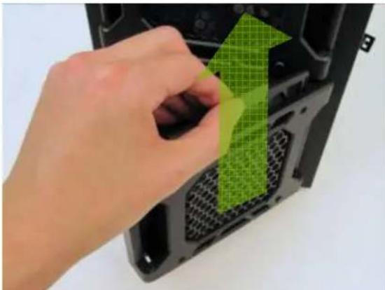
Hand placing a green 3D arrow onto a black CPU socket (no text or symbols visible)Removing the washable air filter. Note the filter tabs.
To clean the filter:
-
Open the Fleet-Release ^TM Access Doors. Locate the filter tab behind the faceplate.
-
Lift the tab right and pull it upwards to remove the filter. See picture.
Note: From time to time it will be necessary to wash the installed air filter. Not washing the air filter will result in higher system temperatures and possible stability problems. We recommend checking the air filter at least once a month initially. The frequency will change depending on system usage (users whose systems run 24/7 will likely have to check/wash more often than those who don't use their systems every day) and on environmental conditions.
Antec, Inc.
47900 Fremont Blvd.
Fremont, CA 94538
tel: 510-770-1200
fax: 510-770-1288
Antec Europe B.V.
Stuttgartstraat 12
3047 AS Rotterdam
The Netherlands
tel: +31 (0) 10 462-2060
fax: +31 (0) 10 437-1752
Technical Support:
US & Canada
1-800-22ANTEC
customersupport@antec.com
Europe
+31 (0) 10 462-2060
europe.techsupport@antec.com
www.antec.com
© Copyright 2010 Antec, Inc. All rights reserved.
All trademarks are the property of their respective owners.
Reproduction in whole or in part without written permission is prohibited.
Printed in China.
Version 1.0.0 06/28/2010


- DF-30 DARKFLEET
- THE ADVANCED GAMING FORCE
- DF-30 USER'S MANUAL
- Disclaimer
- TABLE OF CONTENTS
- SECTION 1: INTRODUCTION
- SECTION 2: HARDWARE INSTALLATION
- SECTION 3: FRONT I/O PORTS
- SECTION 4: COOLING SYSTEM
- SECTION 1
- INTRODUCTION
- Drive bays
- Cooling
- 1.3
- BEFORE/YOU/BEGIN/
- LOCATING/AND/POSITIONING/YOUR/COMPUTER/
- SECTION 2
- HARDWARE
- INSTALLATION
- 2.1
- 2.2
- OTHERBOARD/INSTALLATION
- Before proceeding:
- 2.3///// STANDARD/ATX/POWER/SUPPLY/INSTALLATION/
- CABLE/MANAGEMENT
- 2.5
- INTERNAL 3.5" DEVICE INSTALLATION
- 2.7
- USING THE TOP 2.5" HOT-SWAP BAY
- 2.8
- EXTERNAL 5.25" DEVICE INSTALLATION
- 2.9
- INTERNAL 2.5" DEVICE INSTALLATION
- SECTION 3
- FRONT I/O
- PORTS
- 3.1
- 3.2
- 3.3
- POWER SWITCH / RESET SWITCH / HARD DISK DRIVE LED CONNECTORS
- 3.4
- REWIRING MOTHERBOARD HEADER CONNECTIONS
- SECTION 4
- SYSTEM
- 4.2
- TOP 140 MM TwoCool™ FAN
- 4.3
- FRONT 120 MM BLUE LED FANS
- 4.4
- REAR EXHAUST 120 MM TWOCOOL™ FANS
- 4.5
- OPTIONAL FANS
- 4.6
- WASHABLE AIR FILTERS//
- www.antec.com
Brand : ANTEC
Model : ATDF30
Category : Computer Case