35XTC14-GMQ - Tablet Bretford - Free user manual and instructions
Find the device manual for free 35XTC14-GMQ Bretford in PDF.

| Product Type | Tablet |
| Brand | Bretford |
| Model | 35XTC14-GMQ |
| Screen Size | 10.1 inches |
| Display Resolution | 1920 x 1200 pixels |
| Processor | Quad-core 1.8 GHz |
| RAM | 4 GB |
| Internal Storage | 64 GB |
| Expandable Storage | MicroSD up to 512 GB |
| Battery Capacity | 6000 mAh |
| Battery Life | Up to 10 hours |
| Weight | 1.5 lbs (680 g) |
| Dimensions | 9.5 x 6.5 x 0.3 inches |
| Operating System | Android 11 |
| Connectivity | Wi-Fi 802.11ac, Bluetooth 5.0 |
| Rear Camera | 8 MP |
| Front Camera | 5 MP |
| Charging Port | USB-C |
| Included Accessories | Charger, USB cable, Quick start guide |
| Warranty | 1-year limited warranty |
| Color | Black |
Frequently Asked Questions - 35XTC14-GMQ Bretford
User questions about 35XTC14-GMQ Bretford
0 question about this device. Answer the ones you know or ask your own.
Ask a new question about this device
Download the instructions for your Tablet in PDF format for free! Find your manual 35XTC14-GMQ - Bretford and take your electronic device back in hand. On this page are published all the documents necessary for the use of your device. 35XTC14-GMQ by Bretford.
USER MANUAL 35XTC14-GMQ Bretford
Adjustable Work Center with
CPU Holder and Casters
(30" DEPTH ONLY)
Assembly Instructions
35XTC17
36" wide
one grommet hole
35XTC14
42" wide
one grommet hole
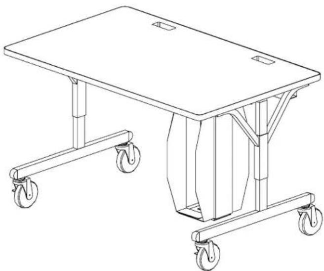
natural_image
Line drawing of a two-wheeled table with wheels, no text or symbols present35XTC18
48" wide
two grommet holes
Parts List
Qty. Part No. Description
1 SA2339 Table Top (36")
SA2340 Table Top (42")
SA2341 Table Top (48")
SA2342 Table Top (72")
2 022-2036 Leg Assembly - Lower
1 022-1589 Leg Assembly - Upper Right
1 022-1590 Leg Assembly - Upper Left
1 010-2321 Modesty Panel (36")
010-3080 Modesty Panel (42")
010-2324 Modesty Panel (48")
010-2706 Modesty Panel (72")
1 010-2322 Cord Bin (36")
010-3081 Cord Bin (42")
010-2325 Cord Bin (48")
010-3075 Cord Bin (72")
2 010-3344 CPU Side Holder-w/hole
(1 required on 35XTC14,
35XTC17 & 35XTC18)
010-4981 CPU Holder w/Hole for MT Models
2 010-3343 CPU Side Holder-w/slot
(1 required on 35XTC14,
35XTC17 & 35XTC18)
010-4980 CPU Holder w/Slot for MT Models
Hardware List
Qty. Ref. Part No. Description
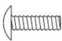
12 AA 030-0402 #10-32 x 5/8" Combo Screw
12 BB 030-0240 Washer, External Tooth
4 CC 030-0396 3/8-16 x 1/2" Set Screw
4 DD 030-0325 1/4-20 x 1/2" Combo Screw
6 EE 030-0168 #8 x 1/2" Wood Screw
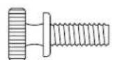
2 FF 030-0433 #10-32 x 1/2" Knurled Knob Screw
2 HH 030-0465 Retaining Washer - Nylon
2 JJ1 015-0002 4" Caster without Lock
2 JJ2 015-0003 4" Caster with Lock
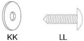
8 KK 030-0305 Washer, Flat (6 required on 35XTC14,
35XTC17 & 35XTC18)
8 LL 030-0453 #12 x 3/4" Phillips Truss Head Screw
(4 required on 35XTC14, 35XTC17 &
35XTC18)
2 MM 030-0272 1/4-20 x 1/2" Carriage Bolt (1 required
on 35XTC14, 35XTC17 & 35XTC18)
2 NN 030-0306 Washer, Flat (1 required on 35XTC14,
35XTC17 & 35XTC18)
2 PP 030-0256 1/4-20 Flanged Nut (1 required on
35XTC14, 35XTC17 & 35XTC18)
1 030-0397 Allen Wrench
Tools Required
Phillips Screwdriver
Rubber Mallet
Allen Wrench (provided)
7/16" Open/Box End Wrench
Electric Drill
1/8" Dia. Drill Bit
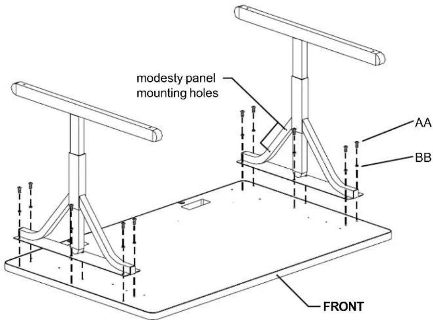
Step 1
Lay the table top on a carpeted surface with holes facing up. Position the legs onto the table top with the modesty panel mounting holes facing inward as shown. Loosely attach legs with screws (AA) and washers (BB).

AA BB
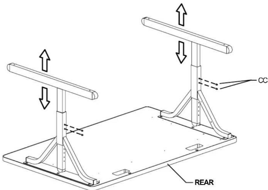
Step 2
Set desired height of legs and insert set screws (CC) into legs and tighten with allen wrench provided.

CC
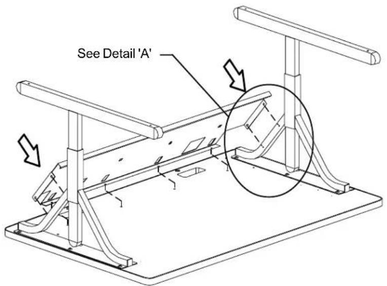
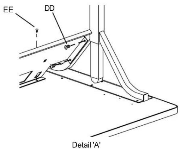
Step 3
Slide the modesty panel between the two legs. Align the modesty panel mounting holes with the leg mounting holes. Loosely install screws (DD). Secure the modesty panel to the table top with screws (EE) as shown in Detail 'A'. Tighten all screws.
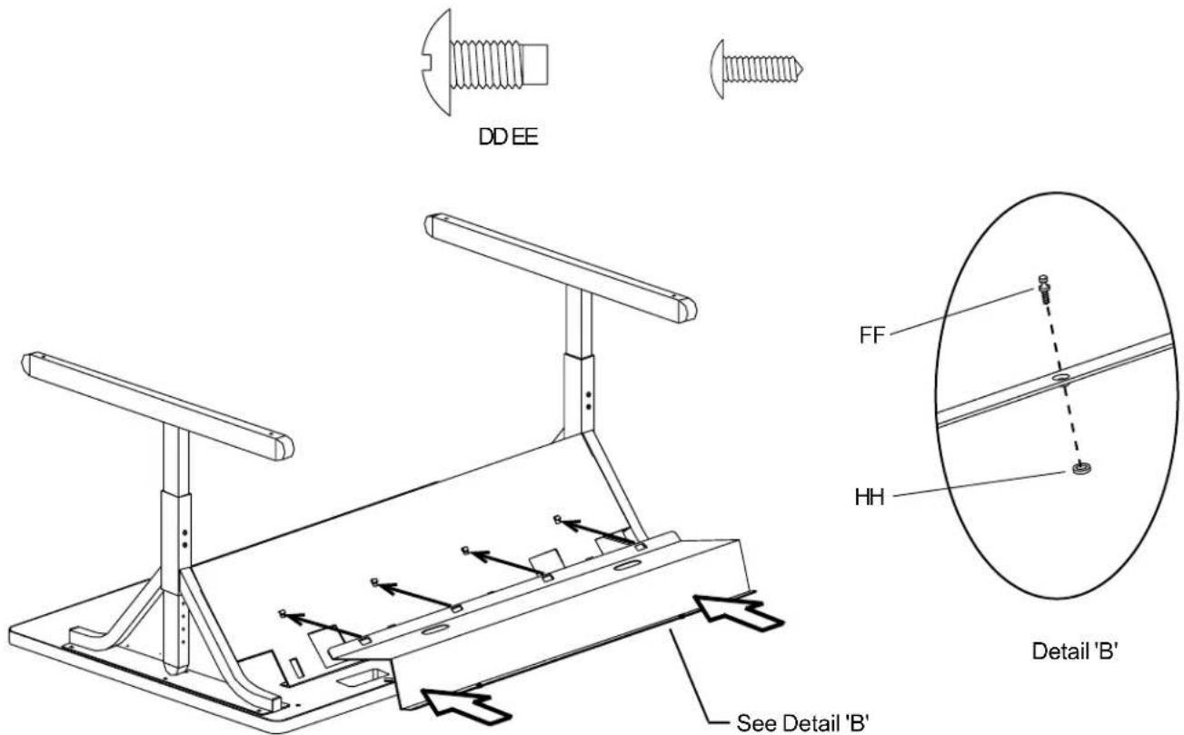
Step 4
Insert screws (FF) into the cord bin flange with the embossed hole(s). Then slide on the nylon washer (HH) to capture the screw (as shown in Detail 'B'). Attach the cord bin to the modesty panel by hooking the rectangular slots onto the modesty panel hooks. Pivot the cord bin down to the table top to align the screw(s) on the embossed flange and tighten.
FF

HH
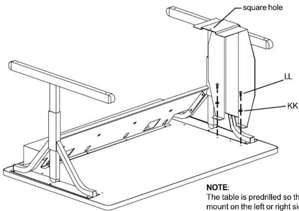
The table is predrilled so the first cpu bracket can mount on the left or right side of your table
Attach the CPU bracket with the square hole located on the bottom flange first. Install with washers (KK) and screws (LL) as shown.
Step 5
Step 6
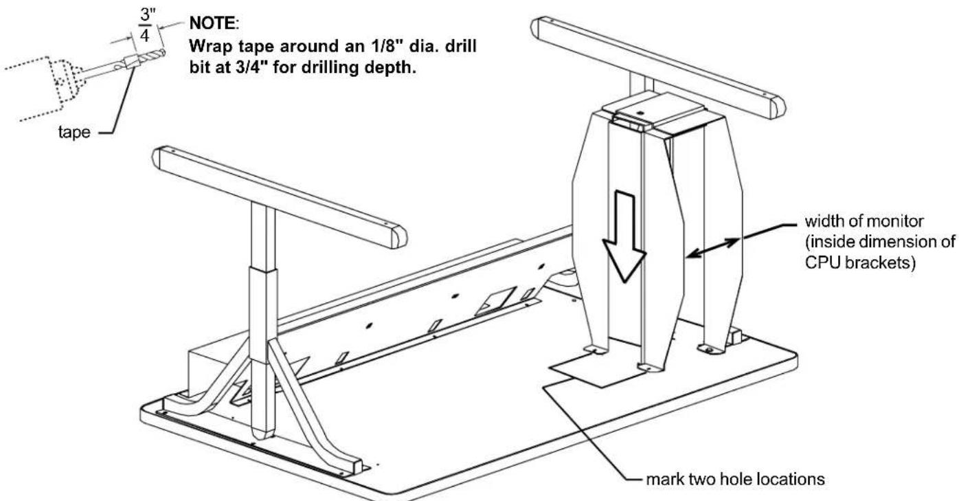
Determine the overall width of your cpu. Place the other CPU bracket over the mounted CPU bracket as shown. Adjust the space between the two brackets by sliding the bracket side to side to equal your cpu width. MAKE SURE THAT THE BRACKETS ARE PARALLEL. Using the CPU bracket as a template, mark the two hole locations for drilling pilot holes. Carefully drill an 1/8" dia. pilot holes 3/4" deep (see note above). Install the second bracket with washers (KK) and screws (LL).
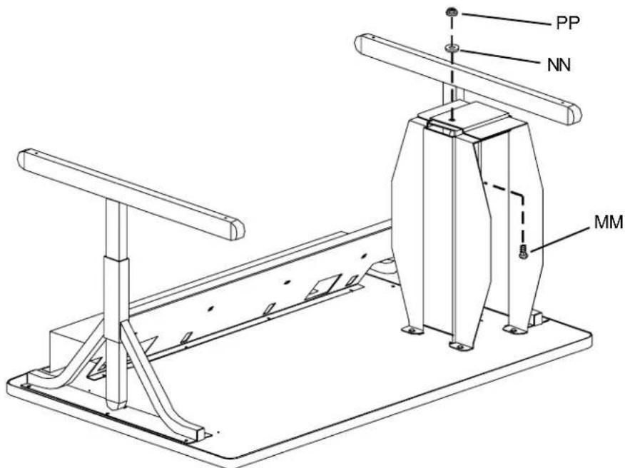
Step 7
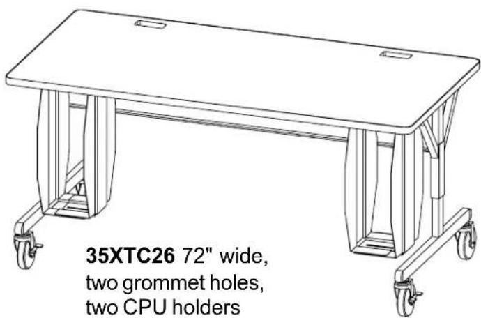
Install carriage bolt (MM) to the inside flange with washer (NN) and nut (PP) on the outside flange as shown. Repeat steps 5, 6 & 7 for 35XTC-26 to install additional holder.
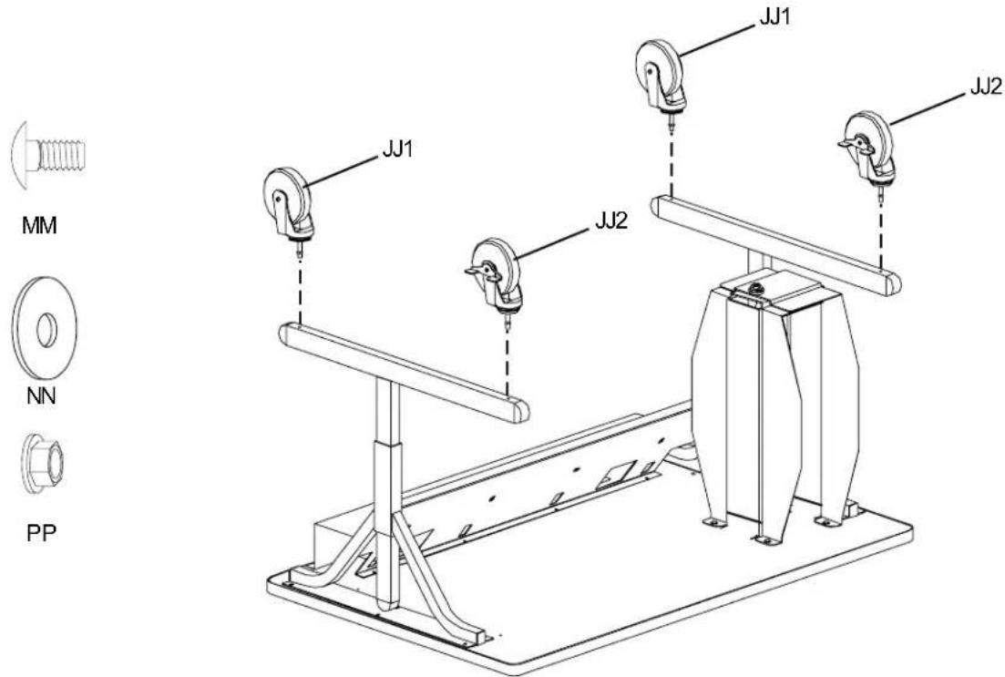
Step 8
Install casters (JJ1) and (JJ2) into leg bottom as shown (a rubber mallet may be required to fully insert the caster stem into leg). Carefully turn over the table and place into position and lock the casters.