
MWR6542B - Microwave Chief - Free user manual and instructions
Find the device manual for free MWR6542B Chief in PDF.


| Product Type | Microwave Oven |
| Brand | Chief |
| Model | MWR6542B |
| Capacity | 0.7 cu ft (20 L) |
| Power Output | 700 W |
| Dimensions (W x D x H) | 17.4 x 13.0 x 10.3 in (44.2 x 33.0 x 26.2 cm) |
| Weight | 21.6 lb (9.8 kg) |
| Power Supply | 120 V / 60 Hz / 1200 W |
| Control Type | Mechanical dials + push buttons |
| Display | Digital timer display |
| Defrost Function | Yes, by weight or time |
| Timer | Up to 60 minutes |
| Turntable | Glass turntable, 10.6 in (27 cm) diameter |
| Interior Light | Yes |
| Child Lock | Yes, press and hold Stop for 3 seconds |
| Door Release | Push-button open |
| Cooking Stages | 1 stage |
| Auto Cook Programs | Yes, 6 pre-set menus (popcorn, potato, pizza, beverage, dinner plate, reheat) |
| Cleaning | Wipe interior with damp cloth; mild detergent |
| Safety Certifications | UL listed |
| Spare Parts Availability | Turntable, glass tray, fuse available via support |
| Repairability Index | 5.5 / 10 (estimated) |
Frequently Asked Questions - MWR6542B Chief
User questions about MWR6542B Chief
0 question about this device. Answer the ones you know or ask your own.
Ask a new question about this device
Download the instructions for your Microwave in PDF format for free! Find your manual MWR6542B - Chief and take your electronic device back in hand. On this page are published all the documents necessary for the use of your device. MWR6542B by Chief.
USER MANUAL MWR6542B Chief
INSTALLATION INSTRUCTIONS

natural_image
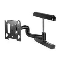
Technical line drawing of a mechanical assembly with mounting brackets and structural components (no text or symbols)Medium Flat Panel Wall Mount
DISCLAIMER
Milestone AV Technologies, and its affiliated corporations and subsidiaries (collectively, "Milestone"), intend to make this manual accurate and complete. However, Milestone makes no claim that the information contained herein covers all details, conditions or variations, nor does it provide for every possible contingency in connection with the installation or use of this product. The information contained in this document is subject to change without notice or obligation of any kind. Milestone makes no representation of warranty, expressed or implied, regarding the information contained herein. Milestone assumes no responsibility for accuracy, completeness or sufficiency of the information contained in this document.
Chief® is a registered trademark of Milestone AV Technologies. All rights reserved.

IMPORTANT WARNINGS AND TIONS!

WARNING: A WARNING alerts you to the possibility of serious injury or death if you do not follow the instructions.

CAUTION: A CAUTION alerts you to the possibility of damage or destruction of equipment if you do not follow the corresponding instructions.

WARNING: Failure to read, thoroughly understand, and follow all instructions can result in serious personal injury, damage to equipment, or voiding of factory warranty! It is the installer's responsibility to make sure all components are properly assembled and installed using the instructions provided.

WARNING: Failure to provide adequate structural strength for the installation of this kit can result in serious personal injury or damage to equipment! It is the installer's responsibility to make sure the structure to which this mount is attached can support five times the combined weight of all equipment.

WARNING: Exceeding the weight capacity can result in serious personal injury or damage to equipment! It is the installer's responsibility to make sure the combined weight of all components attached to this accessory does not exceed 125 lbs (56.7 kg).
LEGEND
| Tgition Fassener |
| Aprieder elemento de fixación |
| Befestigungstell festziehen |
| Aprieder fixador |
| Serrare il fissaggio |
| Bevestiging westtraaten |
| Seriezlos fixations |
| Covente Sachenzy |
| Adjust | |
| Ajustar | |
| Einstellen | |
| Ajustar | |
| Regolare | |
| Afzelien | |
| Ajuster | |
| Пряжоспобарка |
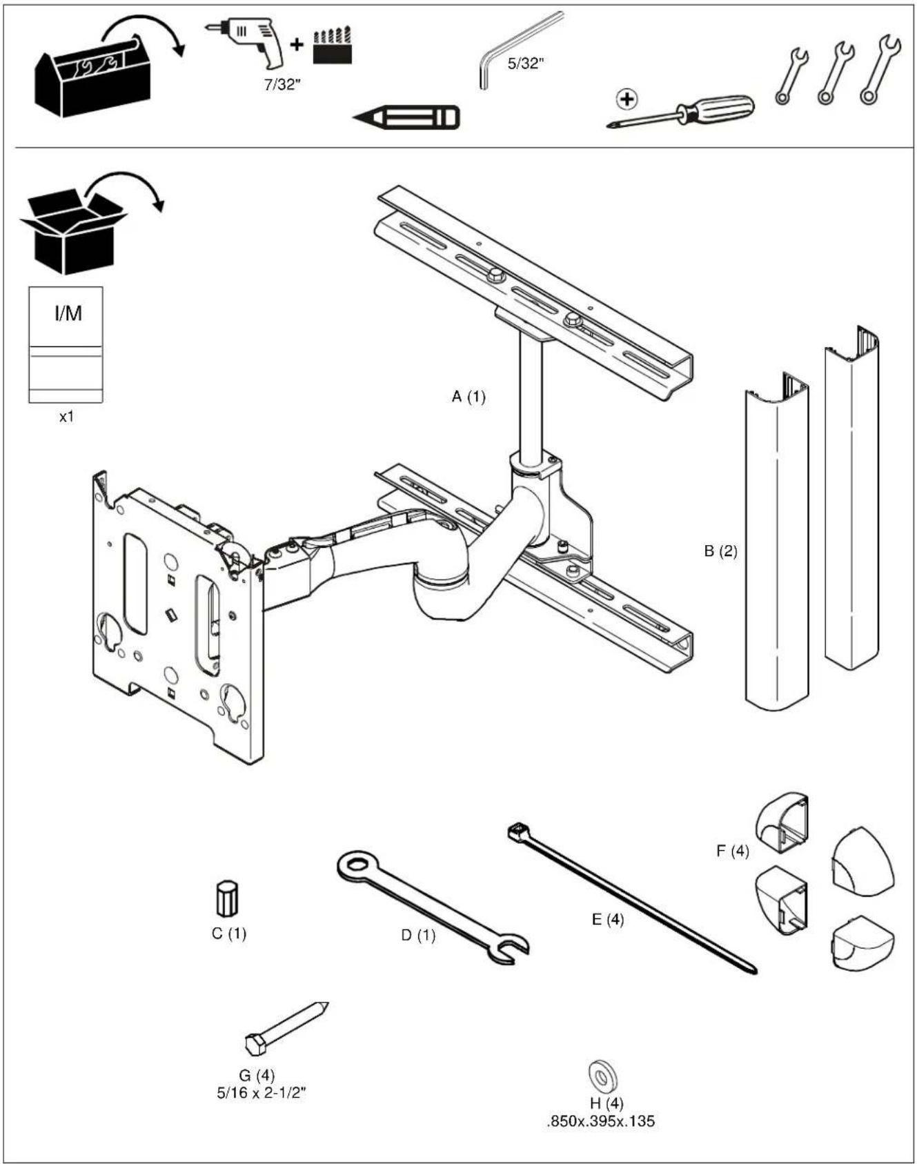
TOOLS REQUIRED FOR INSTALLATION AND PARTS
DIMENSIONS
NOTE: CUSTOM INTERFACE BRACKET NOT SHOWN. THE CUSTOM INTERFACE BRACKET NEEDED FOR YOUR DISPLAY WILL ADD BETWEEN 1/2" AND 2" IN DEPTH AND MAY AFFECT LOCATION OF DISPLAY ON THE MOUNT.
SEE MSB-XXXX DRAWING ALSO.
Mounting Pattern
![[25] 1.00 [178] 7.00 [61] 2.39 [397] 15.65 [64] 2.51 [226] 8.89 [406] 16.00 ISO.](/content/2026/05/1141003/images/90d397cfb6a333707524d6bee969434bb6437bb994e538397fd8dde6bc29c162.jpg)
| PRODUCT FEATURES | |
| WEIGHT CAPACITY | 125 Lbs |
| HEIGHT ADJUSTMENT | 0° |
| TILT / ROLL / YAW | +5°,-15°; ±2.5°/±0° |

ALL MEASUREMENTS ARE IN THE FOLLOWING FORMAT:
[MILLIMETERS] INCHES
Unit Depth
![Extended [632] 24.90](/content/2026/05/1141003/images/698301ae897bb5b33891d3e3399d62634163486f8fe56a6357c3f606f8cd410a.jpg)
Retracted

Tilted Up

Tilt Adjustment
Tilted Down
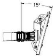
Roll Adjustment

Figure 1
Mount Installation

WARNING: IMPROPER INSTALLATION CAN LEAD TO MOUNT FALLING CAUSING SERIOUS PERSONAL INJURY OR DAMAGE TO EQUIPMENT! It is the installer's responsibility to make sure the structure to which the MWR is being installed is capable of supporting five times the combined weight of the mount and all attachments.
- Determine mounting location taking into consideration display size and mount movement.
- Using a stud sensor locate two wood studs 16" apart on center. (See Figure 2)
- Using two people, place mount against wall and level mount aligning mounting holes in upper and lower wall channels with studs. (See Figure 2)
- Use a pencil mark four mounting holes making sure mounting holes are located as close as possible to center of studs. (See Figure 2)
- Drill four pilot holes where the mounting holes were marked using a 7/32" (6mm) drill bit. (See Figure 2)
- Using two people place mount against wall aligning mounting holes in upper wall channel with pilot holes.
- Install two 5/16" x 2-1/2" lag bolts (G) and two .135" thick washers (H), through upper wall channel and into pilot holes. DO NOT tighten at this time. (See Figure 3)
- Adjust mount lateral position left until lag bolts are seated in mounting slots in upper wall channel.
- Install two 5/16" x 2-1/2" lag bolts (G) and two .135" thick washers (H), through mounting holes in lower wall channel and into pilot holes. (See Figure 3)
- Tighten all hardware. DO NOT overtighten!
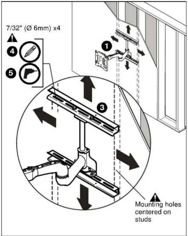
Figure 2

Figure 3
Mount Lateral Position Adjustment
The MWR is designed to allow up to 5" of right or left lateral adjustment after being mounted to the wall. This lateral adjustment can be used to more precisely position where the center of the display is located when installation is complete.
To adjust the mounts lateral position:
- Remove display if installed.
- While holding swing arm, remove two hex head cap screws and two washers securing swing arm to upper wall channel. (See Figure 4)
- While holding swing arm, remove two hex head cap screws and two washers securing swing arm to lower wall channel.
- Set hardware aside for reuse. (See Figure 4)
- Slide swing arm left or right until desired location is reached making sure mounting holes in swing arm upper and lower mounting plates align with mounting slots in upper and lower wall plates. (See Figure 4)
- Secure swing arm to upper and lower wall channels using hex head cap screws and washers set aside during steps 1 and 2. (See Figure 4)

flowchart
graph TD
    A["Hex Head Cap Screw and Washer"] --> B["Upper Swing Arm Mounting Plate"]
    B --> C["Lower Wall Channel"]
    C --> D["Lower Swing Arm Mounting Plate"]
    D --> E["Upper Wall Channel"]
    E --> F["Hex Head Cap Screw and Washer"]
Figure 4
Cover Installation
To install channel covers:
- Install upper and lower wall channel covers (B) by tipping cover top down and positioning as shown in end view of figure below. (See Figure 5)
- Tap firmly across bottom of channels (B) to lock in place as shown in figure below. (See Figure 5)
- Install R.H. and L.H. end caps (F) by aligning tabs on end caps (F) with slots in wall channel covers (B) and sliding tabs in until end caps (F) are flush with wall channel covers (B). (See Figure 5)

Figure 5
Display Installation
If the mounting pattern of the display being installed is a VESA standard 200 x 200 pattern the mounting buttons can be installed directly to the back of the display. If the display has any other mounting pattern an interface bracket must be obtained before proceeding. Consult a Chief Customer Service representative if an interface bracket is required.

WARNING: IMPROPER INSTALLATION CAN LEAD TO MOUNT FALLING CAUSING SEVERE PERSONAL INJURY OR DAMAGE TO EQUIPMENT. Displays can weigh in excess of 40 lbs (18.1kg). ALWAYS use two people and proper lifting techniques when installing display.

WARNING: IMPROPER INSTALLATION CAN LEAD TO MOUNT FALLING CAUSING SEVERE PERSONAL INJURY OR DAMAGE TO EQUIPMENT. Make sure mounting buttons on display are properly seated in mounting holes in faceplate.
To install display:
- Move mount faceplate to extended position by grasping faceplate and pulling outward away from wall. (See Figure 6)
- While supporting both sides of display, align four mounting buttons on display or interface bracket with four mounting holes in faceplate. (See Figure 6)
- Lower display into place listening for audible "click" to ensure recessed area of mounting buttons are properly seated in lower area of mounting holes and "click lock" mechanism has engaged. (See Figure 6) and (See Figure 7)

Figure 6
NOTE: Holes are provided in the faceplate for use with a padlock or similar locking device, if desired. In addition, the pin and nut may be removed from the upper holes and moved to the lower holes for use as a more permanent locking device. (See Figure 7)

Figure 7
CABLE MANAGEMENT

WARNING: IMPROPER INSTALLATION CAN LEAD TO SERIOUS PERSONAL INJURY OR DAMAGE TO EQUIPMENT! Make sure cables do not run through pinch points.
- Loosen front and rear cable clamps on top arm. (See Figure 8)
- Thread cable ties (E) under cable clamps and secure clamps to top arm. (See Figure 8)
- Route power/audio/video cables through the cable channel in top arm (See Figure 8), allowing sufficient slack in cables for left/Right movement of display and swing arm and also swing arm extension and retraction.
- Secure cables to top arm using two cable ties (E).
- Repeat steps 1 through 4 for lower arm.

WARNING: IMPROPER INSTALLATION CAN LEAD TO SERIOUS PERSONAL INJURY OR DAMAGE TO EQUIPMENT! DO NOT route cables through holes in faceplate.

Figure 8
ADJUSTMENTS
Pitch Tension Adjustment
To adjust display pitch tension:
- With display installed, tighten or loosen two screws, one on each side, using a 5/32" hex wrench. (See Figure 9)
- Check for desired tension.
- Repeat Steps 1 and 2 until desired tension is obtained.

Figure 9
Roll Adjustment
The MWR allows for the horizontal alignment (Roll) of the display to be adjusted up to 2^ right or left to level the display after installing.
To adjust Roll:
- Loosen the roll tension adjustment nut located on the back side of the faceplate assembly. (See Figure 10)
- Level display.
- Tighten roll tension adjustment nut. (See Figure 10)

Figure 10
Swing Arm Tension Adjustment
Swing arm tension is pre-set at the factory and is adjusted to accommodate displays with weights near the top of the mounts capacity.
If smaller displays are used it may be difficult to reposition the display after mounting. Swing arm tension can be adjusted to compensate for smaller display by:
The display must be mounted prior to adjusting swing arm tension.
- Locate the adjustment bar (C) and adjustment wrench (D).
- Place adjustment bar (C) into socket head cap screw located at swing arm pivot point. (See Figure 11)
NOTE: The display may need to be repositioned in order to gain access to the tension adjustment screw(s).
- Check swing arm tension. If desired tension is present, tension adjustment is complete. If additional tension adjustment is required, repeat steps 2 thru 4 until desired tension is achieved.
NOTE: If changing from a smaller display to a larger display may be necessary to increase swing arm tension.
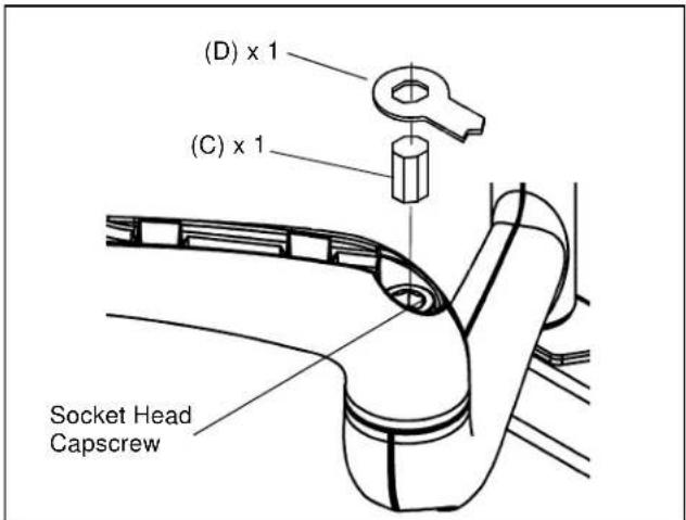
Figure 11
- Using the adjustment wrench (D), turn adjustment bar (C) clockwise to increase swing arm tension or counterclockwise to reduce swing arm tension. (Small adjustments of 1/8 turn or less are typically all that is required to achieve desired tension.) (See Figure 12) and (See Figure 13)
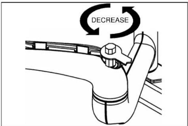
Figure 12

Figure 13
Installation Instructions

Brand : Chief
Model : MWR6542B
Category : Microwave