Suspenders SLS0157 - Lamp Sonneman - Free user manual and instructions
Find the device manual for free Suspenders SLS0157 Sonneman in PDF.

| Product Type | Pendant Light |
| Model | Suspenders SLS0157 |
| Brand | Sonneman |
| Dimensions (Height x Width x Depth) | 24 in x 6 in x 6 in |
| Weight | 2.5 lb |
| Power Supply | Hardwired, 120V AC, 60Hz |
| Maximum Wattage | 40W per bulb (3 bulbs max) |
| Bulb Type | E12 candelabra base, incandescent or LED compatible |
| Dimmable | Yes, with compatible dimmer switch |
| Adjustable Cord Length | Yes, up to 120 in |
| Material | Brushed steel and glass |
| Finish | Brushed Nickel |
| Location Rating | Dry location |
| Safety Certification | UL Listed |
| Installation | Requires junction box (not included) |
| Care Instructions | Wipe with soft, dry cloth; do not use abrasive cleaners |
| Spare Parts | Bulbs available separately; cord replacement possible |
| Warranty | Limited 1 year |
Frequently Asked Questions - Suspenders SLS0157 Sonneman
User questions about Suspenders SLS0157 Sonneman
0 question about this device. Answer the ones you know or ask your own.
Ask a new question about this device
Download the instructions for your Lamp in PDF format for free! Find your manual Suspenders SLS0157 - Sonneman and take your electronic device back in hand. On this page are published all the documents necessary for the use of your device. Suspenders SLS0157 by Sonneman.
USER MANUAL Suspenders SLS0157 Sonneman
natural_image
Pure electrical circuit lines without any symbolsSLS0157
A delicately scaled, modular system of interconnected elements and suspended LED luminaires.
suspenders®
assembly instructions
SONNEMAN®
A WAY OF LIGHT
Suspenders® Product Information and Warnings
Important
- Always disconnect the power before installing or replacing Luminaires and before cleaning or other maintenance.
-
Consult a qualified, licensed electrician to ensure correct branch circuit conductor.
-
Please read all included assembly instructions and warnings carefully before installation. Contact Customer Service if you have any questions or concerns. Before installation, please confirm that the fixture is compatible with your supply voltage and dimming system, if present.
- LEDs are highly sensitive electronic devices, and must be treated with care. Do not open any factory sealed compartments, and avoid touching the LEDs with your hands or any object.
- Although all our fixtures are equipped with protective devices, LED electronic systems are vulnerable to power surges and supply variations. Do not install LED fixtures on the same circuit as any motors, appliances, or HVAC systems.
- Do not remove or bypass any LED Driver or Transformer that is provided with the fixture, and do not replace or substitute with another power supply.
- Remote Transformer installation must be done by a licensed electrician and in accordance with local building and electrical codes. Remote installations should be in an accessible location, as close to the fixture as possible. The appropriate wire gauge must be used to limit the voltage drop to no more than 5%.
- Fixtures must be wired in parallel on independent leads; do not "daisy chain" multiple fixtures together or wire them in series.
- All factory-made splices and connections must remain intact. LED circuits are carefully designed and built, and improper connections may damage the fixture.
- Any mounting hardware is provided for your convenience and should be used with discretion. Always use the appropriate hardware for the mounting surface.
- To avoid excessive voltage drop, the longest electrical path from the Power Feed to the furthest Luminaire should not exceed 30 feet.
- Suspenders® transformers can be loaded up to 80% of their rated wattage.
- Suspenders® transformers feature short-circuit protection with automatic recovery, and will resume operation once the short-circuit condition is removed.
- Suspenders® transformers have 24VAC output, and are dimmable with Electronic Low Voltage dimmers ONLY.
- Suspenders® must be installed in dry locations ONLY.

natural_image
Pure diagram of hanging pendant lights with a horizontal beam, no text or symbols presentConfiguration
Assembly
Suspenders® - Offset Linear Configuration
Assembly Instructions
INSTRUCTIONS D'INSTALLATION
Important
- Shut off power to the outlet box.
- Assemble the Power Feed as shown on page 4.
- Connect one of the upper Power Bars to the Power Feed on one end using the Power Feed Hangers as shown on page 4, and to the ceiling on the other end using the Ceiling Hanger as shown on page 5.
- Connect the other upper Power Bar to the ceiling in line with the first using the Ceiling Hangers as shown on page 5.
- Connect the lower Power Bar to the upper Power Bars using the Parallel Power Bar Hangers as shown on page 5.
- Connect the Luminaire Hangers to the Power Bars as shown on pages 6.
- Connect the Luminaires to the Luminaire Hangers as shown on pages 6-7.
- Restore power to the outlet box.
Note
- This fixture is dimmable with Electronic Low Voltage (i.e., Trailing-Edge/Reverse Phase) type dimmers ONLY.
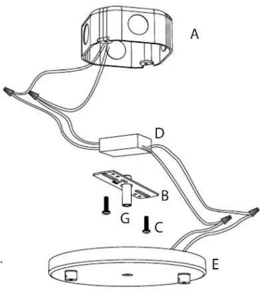
Shallow Power Feed Installation:
- Shut off power to the outlet box (A).
-
For remote transformer use: The transformer (D) must be installed in an accessible location in accordance with local electrical codes. You must use the appropriate wire gauge from the transformer to the Power Feed to limit the voltage drop to less than 5%.
-
Make appropriate electrical connections using wire nuts: a. Connect the transformer's (D) live wire (black) to the live outlet box wire. b. Connect the transformer's neutral wire (white) to the neutral outlet box wire. c. Connect the ground outlet box wire (green or uncoated) to the crossbar using the green screw. d. Connect one of the black Power Feed (E) wires to one of the transformer output wires. Connect the other black Power Feed wire to the second transformer output wire. e. Carefully place connections and transformer (if applicable) in outlet box (A)
-
Attach the crossbar (B) to the outlet box using the two (2) long screws (C).
-
Install the Power Feed (E) to the crossbar (B) by passing the nipple (G) through the hole in the Power Feed and securing with the finial (H).
text_image
A D B G C E
Note
- This fixture is dimmable with Electronic Low Voltage (i.e., Trailing-Edge/Reverse Phase) type dimmers ONLY.
Single Cord Power Feed Hanger:
NOTE: Each Single Cord Power Feed Hanger only carries half of the electrical circuit, and must be used in pairs. To avoid short-circuiting the system, the spring contacts must point in different directions.
- Cut the cord to the desired length, and remove 10mm (3/8") of insulation from the end of each cord. (Fig. 1)
- Twist the wire strands tightly, then insert the exposed wires into the Power Feed bushings. Secure by tightening the set screws with the included Allen key.
- Install the Single Cord Power Feed Hanger onto the Power Bar: pass the cord through the Power Bar, tip the Hanger 45 degrees and insert the copper springs into the center of the Power Bar, then push the Hanger up while tipping it back up 45 degrees.
natural_image
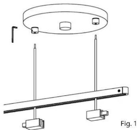
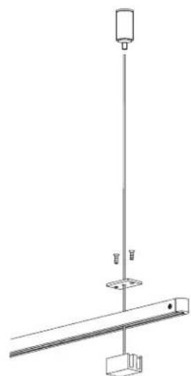
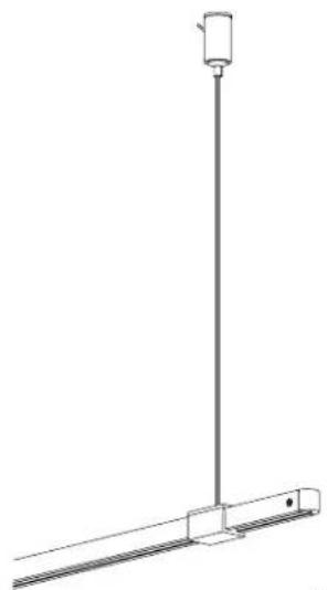
Technical line drawing of a ceiling-mounted fixture with two vertical posts and a circular top fixture (no text or symbols)Cable Ceiling Hanger Assembly:
- Install the mounting bracket to the ceiling with anchor and screw, then screw the post onto the mounting bracket. (Fig. 1)
- Pass the Ceiling Hanger cable through the Power Bar, then through the center hole of the cover, making sure the countersunk holes on the cover are facing up. Attach the cover to the Ceiling Hanger using the two small Phillips screws. (Fig. 2)
- Insert the cable into the post and adjust to the desired length: to shorten, push the cable up; to lengthen, push in the plunger while pulling down on the cable, release the plunger to lock. Cut off the excess cable where it exits the post. (Fig. 3)

natural_image
Technical line drawings of mechanical components including a cylindrical pin, threaded fastener, and cylindrical base (no text or symbols)Fig. 1
natural_image
Pure mechanical diagram showing a vertical rod connected to a horizontal beam with a base, no text or symbols present.Fig. 2
natural_image
Pure technical line drawing of a vertical pole with a cylindrical component, no text or symbols presentFig. 3
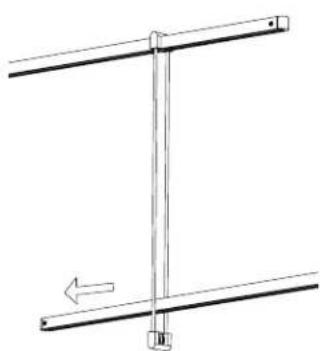
Parallel Power Bar Hanger:
- Pass one end of the Parallel Power Bar Hanger over the end of a Power Bar. (Fig. 4)
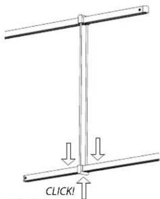
- Press down firmly on the top of the Power Bar Hanger, while pressing up on the bottom of the Power Bar, until the Power Bar Hanger clicks into place. (Fig. 5)
- Pass a second Power Bar between the rods of the Power Bar Hanger. (Fig. 6)
- Press down firmly on the top of the Power Bar, while pressing up on the bottom of the Power Bar Hanger, until the Power Bar clicks into place. (Fig. 7)

natural_image
Simple line drawing of a vertical pole with a horizontal bar and an arrow indicating direction (no text or symbols)Fig. 4

text_image
CLICK!Fig. 5
natural_image
Pure mechanical diagram showing two vertical rods with a central vertical rod and an arrow indicating direction (no text or symbols)Fig. 6
text_image
CLICK!Fig. 7
Connecting a Luminaire Hanger to a Power Bar (Fig. 1):
- Place the Luminaire Hanger over the Power Bar.
- Press down firmly on the top of the Luminaire Hanger, while pressing up on the bottom of the Power Bar, until the Luminaire Hanger clicks into place.
- To remove, tip the Luminaire Hanger in the direction of the Power Bar, then lift the Luminaire Hanger off the Power Bar.

text_image
CLICK! Fig. 1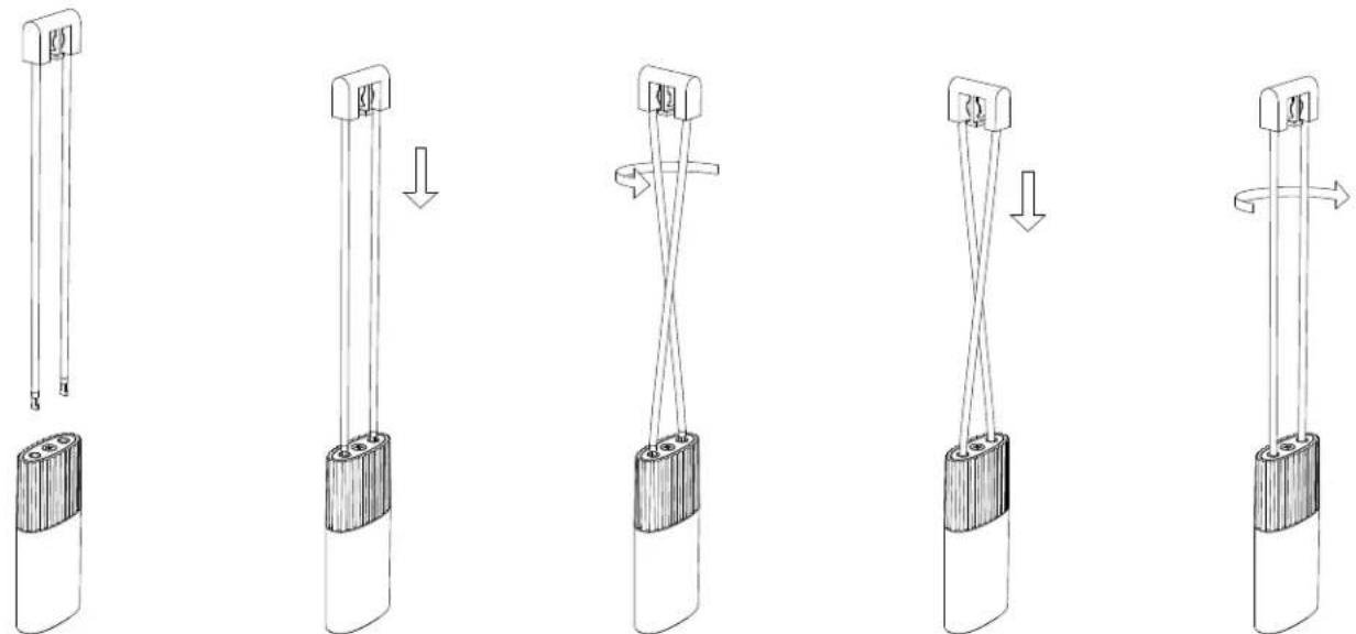
text_image
Diagram illustrating five stages of battery charging mechanism, showing pin arrangement and rotation directionFig. 2
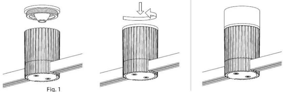
Connecting a Luminaire to a Luminaire Hanger (Fig. 2):
- Gently insert the two Luminaire Hanger rods into the holes on the top of the Luminaire.
- Rotate the Luminaire or Luminaire Hanger 90 degrees.
- Push the Luminaire Hanger rods into the Luminaire until the copper on the ends of the rods is no longer visible.
- Rotate the Luminaire or Luminaire Hanger back 90 degrees to lock.
Connecting a Trim to a Cylinder Light Engine:
- Screw the Trim Ring into the Cylinder Light Engine. (Fig. 1)