
99-8164G - Wiring Kit Metra - Free user manual and instructions
Find the device manual for free 99-8164G Metra in PDF.

| Product Type | Wiring Harness Kit |
| Brand | Metra |
| Model | 99-8164G |
| Compatibility | Select Chrysler, Dodge, Jeep, and Ram vehicles (2004-2013) |
| Harness Length | Approximately 12 inches |
| Wire Gauge | 18 AWG |
| Connector Types | ISO and vehicle-specific connectors |
| Color Coding | Standard aftermarket color code (yellow, red, black, etc.) |
| Package Dimensions | 6.0 x 4.0 x 1.5 inches |
| Package Weight | 0.25 lbs |
| Power Handling | Passive component, no power required |
| Installation | Requires crimping or soldering; wire strippers recommended |
| Safety | Disconnect vehicle battery before installation |
| Maintenance | Keep dry and free of debris; inspect connections periodically |
| Spare Parts | Not available separately; replace entire harness if damaged |
| Repairability | Not designed for repair; replace if faulty |
| Certifications | Meets OEM specifications |
Frequently Asked Questions - 99-8164G Metra
User questions about 99-8164G Metra
0 question about this device. Answer the ones you know or ask your own.
Ask a new question about this device
Download the instructions for your Wiring Kit in PDF format for free! Find your manual 99-8164G - Metra and take your electronic device back in hand. On this page are published all the documents necessary for the use of your device. 99-8164G by Metra.
USER MANUAL 99-8164G Metra
natural_image
Interior view of a car dashboard with digital displays and instrument gauges (no visible text or symbols)Lexus RX300 1999-2003
Visit MetraOnline.com for more detailed information about the product and up-to-date vehicle specific applications
KIT FEATURES
- ISO DDIN radio provision
• ISO DIN radio provision with pocket - Custom texture and painted tan or gray to match the factory appearance
- Touchscreen for retention of climate control functions
- Factory amplifier not retained with this product - an amplifier bypass harness is included
• 99-8164T — Tan w/black trim, 99-8164G — Gray w/black trim
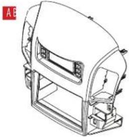
KIT COMPONENTS
- A) Radio trim panel • B) Radio brackets • C) Pocket • D) Panel clips (3) • E) #8 x 3/8" Pan-head Philips screws (8)
• F) Wiring and interfacing (not shown)
natural_image
Technical line drawing of a mechanical device with no visible text or symbols
natural_image
Two mechanical clamps with mounting holes and mounting brackets, shown in line drawing without any text or symbols.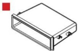
natural_image
Isometric line drawing of a rectangular electronic enclosure or housing with mounting holes (no text or symbols)

TABLE OF CONTENTS
Dash Disassembly 2
Kit Preparation 3
Kit Assembly 4
Axxess Interface Installation 5-11
Final Assembly 9
WIRING & ANTENNA CONNECTIONS
Wiring Harness: Included with kit Antenna Adapter: Not needed
TOOLS REQUIRED
- Panel removal tool • Phillips screwdriver
- 10mm Socket wrench
Attention! Let the vehicle sit with the key out of the ignition for a few minutes before removing the factory radio. When testing the aftermarket equipment, ensure that all factory equipment is connected before cycling the key to ignition.
DASH DISASSEMBLY
- Unsnap and remove the shifter trim. (Figure A)
- Remove (4) 10mm bolts and remove the radio assembly. (Figure B)

natural_image
Interior view of a car headset showing dashboard and steering wheel (no text or symbols visible)(Figure A) (Figure C)
- Depress side tabs to remove the factory hazard button and passenger airbag light from the factory radio assembly. (Figure C)
- Depress all four side tabs to remove the factory vents from the factory radio assembly. (Figure D)
Continue to Kit Preparation

natural_image
Line drawing of a car air conditioning device with control panel and indicator lights (no text or symbols)
natural_image
Line drawing of a car air conditioning device with control panel and display screen (no text or symbols)
natural_image
Top-down schematic of a vehicle dashboard with front, rear, and side panels (no text or symbols)(Figure B) (Figure D)
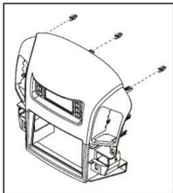
KIT PREPARATION
- Attach the (3) supplied panel clips to the radio trim panel. (Figure A)
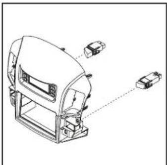
- Snap the passenger airbag light and hazard button into the radio trim panel from the back. (Figure B)
- Attach the factory vents to the radio trim panel (Figure C)
Continue to Kit Assembly
natural_image
Technical line drawing of a mechanical device with mounting brackets and control panel (no text or symbols)(Figure A)
natural_image
Technical line drawing of a device casing with internal components and alignment indicators (no text or symbols)(Figure B) (Figure C)

natural_image
Technical line drawing of a mechanical assembly with three labeled components (no text or symbols present)KIT ASSEMBLY
ISO-DIN radio provision with pocket
- Secure the pocket to the radio brackets using the (4) #8 x 3/8" Phillips screws supplied. (Figure A)
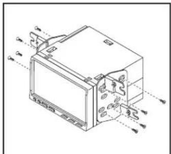
- Attach the radio bracket/pocket assembly to the radio using screws supplied with the radio. (Figure B)
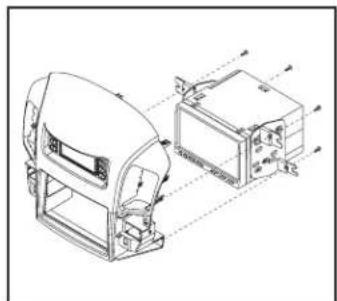
- Attach the completed assembly to the radio trim panel using the supplied (4) #8 x 3/8" Phillips screws. (Figure C)
Continue to Axxess Interface Installation
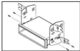
natural_image
Technical line drawing of a mechanical bracket assembly (no text or symbols)(Figure A)

natural_image
Technical line drawing of a device housing with mounting holes and ventilation slots (no text or symbols)(Figure B)

natural_image
Technical line drawing of a mechanical device with internal components and alignment lines (no text or symbols)(Figure C)
ISO-DDIN radio provision
- Secure the radio brackets to the radio using screws supplied with the radio. (Figure A)
- Attach the completed assembly to the radio trim panel using the supplied (4) #8 x 3/8" Phillips screws. (Figure B)
Continue to Axxess Interface Installation
(Figure A)
natural_image
Technical line drawing of a device with internal components and mounting brackets (no text or symbols)(Figure B)
AXXESS INTERFACE INSTALLATION
INTERFACE FEATURES
- Provides accessory power (12-volt 10-amp)
• Retains R.A.P. (retained accessory power) - Touchscreen for retention of climate control functions
- Micro "B" USB updatable
TABLE OF CONTENTS
Connections......6-8
Installation 9
Programming....9
Touchscreen display operation....10-11
INTERFACE COMPONENTS
- Axxess interface (built into the touchscreen display)
- Bean Bus interface
• 8164 harness
• 8164 NAV harness
• 4-pin harness with yellow RCA jacks - Factory amplifier not retained with this product – an amplifier bypass harness included
TOOLS REQUIRED
- Crimping tool and connectors, or solder gun, solder, and heat shrink • Tape
- Wire cutter • Zip ties
CONNECTIONS
From the LD-8164 harness to the aftermarket radio:
- Connect the Black wire to the ground wire.
- Connect the Yellow wire to the battery wire.
- Connect Red wire to the accessory wire.
- Tape off and disregard the following (4) wires, they will not be used in this application: Gray, Gray/Black, White, White/Black
*For speaker wire connections, refer to the AX-AB-LX4 amplifier bypass harness Instructions
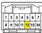
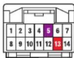
The Yellow/Black 'Bean BUS' wire must be connected properly for this interface to function: Locate the 13 pin connector in the vehicle.
The following connections will have to be made.
- 'Bean BUS (Yellow/Black)' – to the factory Yellow/Black wire.
- Radio's Illumination wire – to the factory Green wire (if desired)
Front of 13 pin connector

Wire side of 13 pin connector

CONNECTIONS (CONT.)
Use the LD-8164-NAV harness for vehicles with Factory Navigation
From the LD-8164-NAV harness to the aftermarket radio:
- Connect Black to the ground wire
- Connect Yellow to the battery/ memory wire.
- Connect Red to the accessory wire.
- Connect Orange to the Illumination wire.
- Connect Blue to the radio's Antenna/Remote wire.
- Tape off and disregard the following wires: White, White/Black, Gray, and Gray/Black.*
*For speaker wire connections, refer to the AX-AB-LX4 amplifier bypass harness Instructions.
The Yellow/Black 'Bean BUS' wire must be connected properly for this interface to function:
Locate the gray 14 pin connector in the vehicle.
The following connections will have to be made.
- Connect the Yellow/Black wire labelled 'Bean BUS' to the Yellow/Black wire on the factory connector.
A military/lineman splice is recommended to ensure a good connection.*
*Always insulate all connections.
Gray (Control Panel)
Yellow/Black – 'Bean BUS' wire
- Connect to labeled wire on LD-8164
The following connections are only necessary if installing a Multimedia / Navigation radio & desire the additional outputs:
- Connect the radios Vehicle Speed Sense wire to the factory Violet/White wire.
- Connect the radios Park wire to the factory Red/White wire.
White (Multi Display)
Violet/White – Vehicle Speed Sense
Red/White – Parking Brake
CONNECTIONS (CONT.)
4-pin harness with yellow RCA jacks:
- Backup camera harness (4-pin harness with yellow RCA jacks):
- There are two different methods for connecting an aftermarket camera. To the touchscreen or to the aftermarket radio (see radio manual)
- If connecting a backup camera to the touchscreen display is desired, connect the Yellow RCA jack labeled "Rearview camera", to the aftermarket camera.
• IF this method is chosen, see camera options in the Configuration Settings section. - Disregard the Yellow RCA jack labeled "AUX video", it will not be used in this application.
Amplifier bypass:
Use the included amplifier bypass to connect to the speakers. Take note that there are multiple speakers with varying impedance. An external amplifier and crossovers are recommended.
AX-AB-LX4:
From the 10p Connector:
Green Rear Left Door Speaker (+) Green/Black Rear Left Door Speaker (-) Gray Front Right Speaker / Tweeter (+) Gray/Black Front Right Speaker / Tweeter (-) White Front Left Speaker / Tweeter (+) White/Black Front Left Speaker / Tweeter (-)
From the 6p Connector:
Green/White Subwoofer 1 (+) (If applicable)
White/Red Subwoofer 1 (-) (If applicable)
Purple Rear Right Door Speaker (+)
Purple/Black Rear Right Door Speaker (-)
Brown/Yellow Subwoofer (+)
Brown/Blue Subwoofer (-)
INSTALLING THE INTERFACE
It is highly advisable to read the following steps beforehand, to ensure a clear understanding of what is to be expected. The following steps must be done in the order that they are numbered.
With the vehicle completely off:
Touchscreen display
- Connect the 8164 harness to the wiring harnesses in the vehicle. Then insert the 8164 harness into port "A" in the touchscreen display.
- If adding an aftermarket back-up camera to the touchscreen. Connect the 4-pin harness with yellow RCA jacks into port "C" in the touchscreen display.
- Disregard port "E" and "B" and "D", it will not be used in this application.
- Port "F" is an update port for future firmware upgrades.

- Locate the factory antenna connector in the dash and complete all necessary connections to the radio. Metra recommends using the proper mating adapter from Metra.
PROGRAMMING
- Open the drivers door and keep open during the process.
- Cycle the ignition to on.
- Connect the harnessing to the vehicle.
- Wait until the radio powers on and the touchscreen displays "SWC configured".
• Cycle the ignition off and back on. - Test all functions.
FINAL ASSEMBLY
- Secure the completed assembly into the dash using the factory hardware and reassemble the dash in reverse order of disassembly.
HVAC control screen Configuration Settings screen

- This is the HVAC control screen which will be displayed on the touchscreen display. This is considered the main screen.
- The upper right tab with the gear icon will take you to the Configuration Settings screen.
- The climate controls will function in the same manner that they did with the factory climate controls.
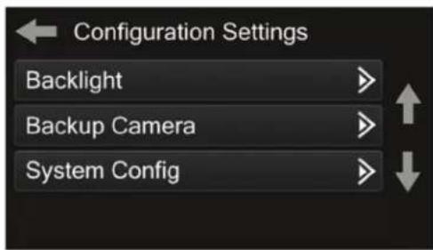
Backlight
- For controlling the color of the buttons and back-light intensity.
Backup Camera
- Enable/disable the backup camera image to the touchscreen display. Disabled by default.
System Configuration
- About - Information regarding the software in the kit.
- Vehicle Config – Factory features.
- Reset Vehicle Type - To reset the kit to default settings.
Touchscreen calibration:
- Press and hold the upper two soft buttons on either side of the touchscreen for 10 seconds.
- A screen will pop up asking for you to press the target in the screen.
- After pressing the target with your finger, the calibration process will be complete, and the screen will disappear.
Having difficulties? We're here to help.

our Tech Support line at:
386-257-1187

mail at:
techsupport@metra-autosound.com
Tech Support Hours (Eastern Standard Time)
Monday - Friday: 9:00 AM - 7:00 PM
Saturday: 10:00 AM - 7:00 PM
Sunday: 10:00 AM - 4:00 PM

KNOWLEDGE IS POWER
Enhance your installation and fabrication skills by sampling in the most recognized and supported
mobile electronics school in our industry.
Log onto www.installennstitute.com or call
600-934-6782 for more information and take steps toward a better tomorrow.

Metra recommends MECP certified technicians

- Lexus RX300 1999-2003
- KIT FEATURES
- KIT COMPONENTS
- TABLE OF CONTENTS
- WIRING & ANTENNA CONNECTIONS
- TOOLS REQUIRED
- DASH DISASSEMBLY
- KIT PREPARATION
- KIT ASSEMBLY
- ISO-DIN radio provision with pocket
- ISO-DDIN radio provision
- AXXESS INTERFACE INSTALLATION
- INTERFACE FEATURES
- INTERFACE COMPONENTS
- CONNECTIONS
- From the LD-8164 harness to the aftermarket radio:
- CONNECTIONS (CONT.)
- Use the LD-8164-NAV harness for vehicles with Factory Navigation
- From the LD-8164-NAV harness to the aftermarket radio:
- 4-pin harness with yellow RCA jacks:
- AX-AB-LX4:
- INSTALLING THE INTERFACE
- With the vehicle completely off:
- Touchscreen display
- PROGRAMMING
- FINAL ASSEMBLY
- Backlight
- Backup Camera
- System Configuration
- Touchscreen calibration:
- Tech Support Hours (Eastern Standard Time)
Brand : Metra
Model : 99-8164G
Category : Wiring Kit