
95-6539 - Wiring Kit Metra - Free user manual and instructions
Find the device manual for free 95-6539 Metra in PDF.

| Product Type | Wiring Harness Kit |
| Brand | Metra |
| Model | 95-6539 |
| Compatible Vehicles | Select 1994-up Toyota, Lexus, Scion with factory amplifier (verify fitment) |
| Connector Type | Plug-and-play with factory connectors |
| Wire Gauge | 18 AWG (speaker wires), 16 AWG (power wires) |
| Included Components | Harness, instruction sheet |
| Dimensions (Harness) | Approximately 12 x 4 x 2 inches (30 x 10 x 5 cm) |
| Weight | 0.4 lbs (180 g) |
| Material | PVC insulated copper wire, high-temperature thermoplastic connectors |
| Power Handling | Up to 50W RMS per channel |
| Installation Difficulty | Easy, no cutting required for compatible vehicles |
| Function | Retains factory amplifier and speakers when installing aftermarket radio |
| Input | Aftermarket radio harness (standard ISO or Metra connector) |
| Output | Factory amplifier connector |
| Safety Features | Color-coded wires for easy identification, strain relief |
| Maintenance | Keep connectors dry and free of corrosion; inspect periodically |
| Repairability | Replacement harness available; defective units warranty |
| Certifications | Meets OEM specifications; RoHS compliant |
Frequently Asked Questions - 95-6539 Metra
User questions about 95-6539 Metra
0 question about this device. Answer the ones you know or ask your own.
Ask a new question about this device
Download the instructions for your Wiring Kit in PDF format for free! Find your manual 95-6539 - Metra and take your electronic device back in hand. On this page are published all the documents necessary for the use of your device. 95-6539 by Metra.
USER MANUAL 95-6539 Metra
natural_image
Interior view of a car dashboard with digital display and steering wheel (no visible text or symbols)KIT FEATURES
• ISO DDIN radio provision
KIT COMPONENTS
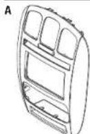
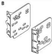
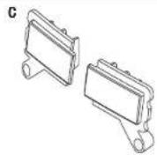
- A) Radio trim panel • B) Radio brackets • C) (2) Blank out plugs • D) (6) Panel clips - E) (2) #8 x 3/8" Phillips screws • Passenger airbag sticker (not shown) • Blank sticker (not shown)


WIRING & ANTENNA CONNECTIONS (sold separately)
Wiring Harness: • 70-1817 (01' only) 70-6502 (02-07' models) Antenna Adapter: • 40-CR10 (02-07' models only) Steering wheel control interface: • ASWC-1
Table of Contents
Dash Disassembly 2
Kit Preparation....2-3
Kit Assembly 4
TOOLS REQUIRED
- Panel removal tool - Phillips screwdriver - Torx T-10 screwdriver
CAUTION! All accessories, switches, climate controls panels, and especially air bag indicator lights must be connected before cycling the ignition. Also, do not remove the factory radio with the key in the on position, or while the vehicle is running.
95-6539
Dash Disassembly Kit Preparation
- Open cup holder. Unclip and remove trim above cup holder.
- Remove (2) Phillips head screws from above cup holder. (Figure A)
- Unclip and remove the dash trim panel.
- Remove (4) Phillips head screws securing the radio. Disconnect and remove the radio.
Continue to Kit Preparation
natural_image
Line drawing of a car air conditioner unit with two views (front and side), no text or symbols present(Figure A)
From the factory radio/climate control panel:
- Remove (3) T-10 Torx screws securing the vents into the factory radio trim panel, then unclip and remove the vents from the panel.
- Remove (3) T-10 Torx screws securing the hazard button assembly into the factory radio trim panel, remove the switch assembly.
Note: If the vehicle has the passenger airbag light in the factory radio panel, it will be loose at this time, so remove it. If the passenger airbag light is not present or it is in the hazard switch assembly, continue to the next step.
- Remove (6) T-10 Torx screws securing the climate controls into the factory radio trim panel, and then remove.
Continued on the next page
Please visit Metraonline.com for Kit Preparation illustrations.

95-6539
Kit Preparation
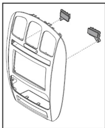
Sticker notes:
If the vehicle has a passenger airbag light in the factory radio trim panel above the switches, place the passenger airbag sticker over the hole for the airbag light above the hazard switch on the 95-6539 radio trim panel.
If the vehicle has a passenger airbag light above the hazard switch assembly, snap the blank out plugs into the opening on either side of the switch assembly, and then secure using the (2) #8 x 3/8" Phillips screws provided. And then place the blank sticker over the airbag light hole above the hazard switch on the 95-6539 radio trim panel. (Figure A)
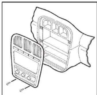
natural_image
Technical line drawing of a car dashboard frame with two connectors and internal compartments (no text or symbols)(Figure A)
To the 95-6539 radio trim panel:
- Attach the passenger airbag light from the factory radio panel, into the back of the 95-6539 radio trim panel.
- Attach the climate controls into the 95-6539 radio trim panel using the factory hardware.
- Attach the vents into the 95-6539 radio trim panel and secure with the factory screws.
- Attach the hazard switch assembly into the 95-6539 radio trim panel and secure with the factory hardware (this will also secure the passenger airbag light noted in step 2).
- Attach the (6) panel clips to the new radio trim panel.
- Cut and remove shaded area in the sub-dash of the vehicle. (Figure B)
Continue to Kit Assembly

natural_image
Mechanical assembly diagram showing a bracket with mounting holes and a directional arrow indicating movement (no text or symbols present)(Figure B)
95-6539
Kit Assembly
ISO DDIN radio provision
- Attach the radio brackets to the radio using the screws supplied with the radio. (Figure A)
- Locate the factory wiring harness and antenna connector in the dash and complete all necessary connections to the radio. Metra recommends using the proper mating adapter from Metra and/or Axxess. Test the radio for proper operation.
- Secure the completed assembly into the dash using the factory screws.
- Attach the 95-6539 radio trim panel over the completed assembly, and then reassemble the dash in reverse order of disassembly.

natural_image
Technical line drawing of an electronic device with labeled ports and wiring (no text or symbols present)(Figure A)
INSTALLATION INSTRUCTIONS FOR PART 99-8260B

IMPORTANT
If you are having difficulties with the installation of this product, please call our Tech Support line at 1-800-253-TECH. Before doing so, look over the instructions a second time, and make sure the installation was performed exactly as the instructions are stated. Please have the vehicle apart and ready to perform troubleshooting steps before calling.

KNOWLEDGE IS POWER
Enhance your installation and fabrication skills by enrolling in the most recognized and respected mobile electronics school in our industry. Log onto www.installerInstitute.com or call 800-354-6782 for more information and take steps toward a better tomorrow.

Metra recommends MECP certified technicians

- KIT FEATURES
- KIT COMPONENTS
- WIRING & ANTENNA CONNECTIONS (sold separately)
- Table of Contents
- TOOLS REQUIRED
- Dash Disassembly Kit Preparation
- From the factory radio/climate control panel:
- Kit Preparation
- Sticker notes:
- To the 95-6539 radio trim panel:
- Kit Assembly
- ISO DDIN radio provision
- IMPORTANT
- KNOWLEDGE IS POWER
Brand : Metra
Model : 95-6539
Category : Wiring Kit