10-110 - Saw RIKON - Free user manual and instructions
Find the device manual for free 10-110 RIKON in PDF.

| Product Type | Table Saw |
| Brand | RIKON |
| Model | 10-110 |
| Blade Diameter | 10" (254 mm) |
| Max Depth of Cut | 3-1/8" (79.4 mm) |
| Max Depth of Cut at 45° | 2-1/8" (54 mm) |
| Table in Front of Blade | 13-7/8" (352 mm) |
| Max Dado Width | 29/32" (23 mm) |
| Blade Speed | 4300 RPM |
| Motor Power | 3 HP (2.24 kW) |
| Voltage / Frequency | 230V / 60Hz |
| Current | 13 A |
| Overall Height | 37-1/2" (953 mm) |
| Net Weight | 615 lbs (279 kg) |
| Table Material | Cast iron |
| Included Accessories | Right extension wing, fence assembly, blade guard, splitter, push sticks, wrench set |
| Safety Features | Blade guard, splitter, emergency stop paddle, grounding plug |
| Maintenance | Keep table clean, wax to prevent rust, check blade alignment, lubricate moving parts |
| Warranty | 2-year limited warranty |
Frequently Asked Questions - 10-110 RIKON
User questions about 10-110 RIKON
0 question about this device. Answer the ones you know or ask your own.
Ask a new question about this device
Download the instructions for your Saw in PDF format for free! Find your manual 10-110 - RIKON and take your electronic device back in hand. On this page are published all the documents necessary for the use of your device. 10-110 by RIKON.
USER MANUAL 10-110 RIKON
natural_image
Industrial machine with RIKON branding and metal frame (no visible text or symbols on main body)Record the serial number and date of purchase in your manual for future reference.
Serial number: ____
Date of purchase: ____
For more information:
www.rikontools.com or info@rikontools.com
For Parts or Questions:
Operator Safety: Required Reading
IMPORTANT! Safety is the single most important consideration in the operation of this equipment. The following instructions must be followed at all times.
There are certain applications for which this tool was designed. We strongly recommend that this tool not be modified and/or used for any other application other than that for which it was designed. If you have any questions about its application, do not use the tool until you have contacted us and we have advised you.
General Safety Warnings
KNOW YOUR POWER TOOL. Read the owner's manual carefully. Learn the tool's applications, work capabilities, and its specific potential hazards.
DANGER

ALWAYS GROUND ALL TOOLS.
If your tool is equipped with a three-pronged plug, you must plug it into a three-hole electric receptacle. If you use an adapter to accommodate a two-pronged receptacle, you must attach the adapter plug to a known ground. Never remove the third prong of the plug.
ALWAYS AVOID DANGEROUS ENVIRONMENTS.
Never use power tools in damp or wet locations. Keep your work area well lighted and clear of clutter.
DANGER

ALWAYS REMOVE THE ADJUSTING KEYS AND WRENCHES FROM TOOLS AFTER USE.
Form the habit of checking to see that keys and adjusting wrenches are removed from the tool before turning it on.
ALWAYS KEEP YOUR WORK AREA CLEAN. Cluttered areas and benches invite accidents.
▲ DANGER

ALWAYS KEEP VISITORS AWAY FROM RUNNING MACHINES.
All visitors should be kept a safe distance from the work area.
ALWAYS MAKE THE WORKSHOP CHILDPROOF.
Childproof with padlocks, master switches, or by removing starter keys.
DANGER

NEVER OPERATE A TOOL WHILE UNDER THE INFLUENCE OF DRUGS, MEDICATION, OR ALCOHOL
DANGER

ALWAYS WEAR PROPER APPAREL.
Never wear loose clothing or jewelry that might get caught in moving parts. Rubber-soled footwear is recommended for the best footing.
DANGER

ALWAYS USE SAFETY GLASSES AND WEAR HEARING PROTECTION.
▲ DANGER

NEVER OVERREACH.
Keep your proper footing and balance at all times.
DANGER

Serious injury could occur if the tool is tipped or if the cutting tool is accidentally contacted.
DANGER
ALWAYS DISCONNECT TOOLS.
Disconnect tools before servicing and when changing accessories such as blades, bits, and cutters.

ALWAYS AVOID ACCIDENTAL STARTING.
Make sure switch is in "OFF" position before plugging in cord.
NEVER LEAVE TOOLS RUNNING UNATTENDED.
DANGER
ALWAYS CHECK FOR DAMAGED PARTS.

Before initial or continual use of the tool, a guard or other part that is damaged should be checked to assure that it will operate properly and perform its intended function. Check for alignment of moving parts, binding of moving parts, breakage of parts, mounting, and any other conditions that may affect its operation. A guard or other damaged parts should immediately be properly repaired or replaced.
Table Saw Safety Rules
- Always wear eye protection.
- Keep hands away from the saw blade while machine is running.
- Always use blade guard during normal cutting operations.
- Always use splitter during normal cutting operations.
- Use push sticks when ripping narrow stock.
- Always use fence while ripping and miter gauge while cross-cutting.
- Never reach over or behind saw blade while machine is running.
- Do not remove cut-off or jammed pieces until blade has come to a full stop.
- Disconnect machine from power source before making repairs or adjustments.
- Do not expose saw or power cord to water or use in damp locations.
SAVE THESE INSTRUCTIONS.
Refer to them often.
Table of Contents
Safety Warnings....2 -3
Table Saw Safety Rules ....3
Specifications 4
Contents of Package 5
Unpacking and Checking Contents 5
Loose Parts 6
Getting To Know Your Table Saw 7
Assembly 8
Installing the Right Table Wing....8
Installing the Optional Left Table Wing....8
Installing the Optional Sliding Table....9
Installing Front Fence Rail 9
RearFenceRailInstallation....9-10
Mounting the Fence Guide Bar....10
Installing Fence to Guide Bar 10
Installing the Fence Scale....11
Leveling Fence to Saw Table 11
Squaring Fence to Table 12
Fence Cursor Adjustment ....12
Blade Guard and Splitter Installation....13
Blade Installation and Removal....14
Leveling the Blade Insert 14
Operation 15
Raising and Tilting the Saw Blade....15
Switch Operation....15
Maintenance 16
Wiring Diagram 16
Troubleshooting 17
Electrical Requirements....18
Parts Diagram 19-21
Parts List 22-23
Warranty 26
Specifications
| Blade Diameter | 10" |
| Maximum Depth of Cut | 3-1/8" |
| Maximum Depth of Cut at 45° | 2-1/8" |
| Table in Front of Blade | 13-7/8" |
| Maximum Width of Dado | 29/32" |
| Blade Speed | 4300RPM |
| Motor Power | 3HP |
| Volts | 230V / 60Hz |
| Current | 13A |
| Height | 37-1/2" |
| Net Weight | 615 lbs |
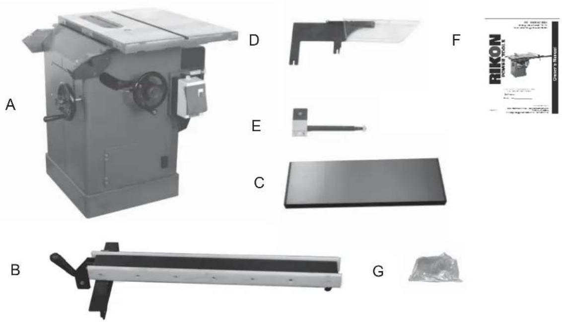
Content of Package
Model 10-050 10" Table Saw is shipped complete in three boxes.
1. Unpacking and Checking Contents
a. Separate all "loose parts" from packaging materials and check each item with "Table of Loose Parts" to make sure all items are accounted for, before discarding any packaging material.
b. With the help of another person, unbolt the table saw from the packing pallet. Properly lift the table saw off the packing pallet and place on level floor.
c. Remove protective oil that is applied to the table. Use any ordinary house hold type grease or spot remover.
d. Apply a coat of paste wax to the table to prevent rust. Wipe all parts thoroughly with a clean dry cloth.
2. Loose Parts
TABLE OF LOOSE PARTS
| Item | Part Name | Qty | |||
| A | Table | Saw | Assembly | 1 | |
| B | Fence | Assembly | 1 | ||
| C | Right | Extension | Wing | 1 | |
| D | Blade | Guard | Assembly | 1 | |
| E | Blade | Guard | Support | 1 | |
| F | Owner's | manual | 1 | ||
| G | Bag of loose parts | 1 | |||
Box #1
Loose Parts Continued
TABLE OF LOOSE PARTS
| Item Part Name | Qty | ||
| A | Rear | Guide | Rail |
| B Front Guide Rail | 1 |
Box #2

natural_image
Two parallel gray cylindrical objects labeled A and B, with no visible text or symbols on the surfaces.TABLE OF LOOSE PARTS
| Item | Part Name | Qty | |||
| A | Left | Extension | Wing | 1 | |
| B | Bag of loose parts | 1 | |||
Box #3

natural_image
Metal plate with two horizontal lines, labeled 'A' on the left (no other text or symbols)B

Getting To Know Your Table Saw

A. Right Extension Wing
B. Left Extension Wing
C. Blade Guard Assembly
D. Switch
E. Fence Assembly
F. Rear Rail
G. Front Rail
H. Tool Holder
I. Motor Cover
J. Blade Tilting Handwheel
K. Blade Raise/down Handwheel
Assembly
Installing the Right Table Wing
- Mount the cast iron table wing using three M10x30 hex head bolts and three M10 fl at washers. Figure 1.
With assistance hold the extension wing up to the table, and insert the bolts and washers. Finger tighten only.
NOTE: If assistance is not available, hold the wing in vertical position up to the saw table, insert the middle screw and lock washer fi nger tight, then pivot the wing to level position. Insert the other two screws and washers fi nger tight.
-
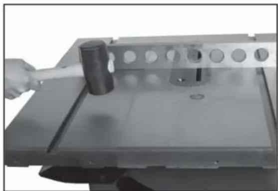
Align table wing toward the front edge of the saw table until the two faces are fl ush. Figure 2.
-
Level table wing with the saw table across its entire width, using a straight edge and hammer with rubber hammer (or block of wood). Figure 3.
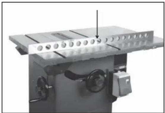
As each section of the table wing becomes flush with the table, tighten the screw under that area. Continue until all three screws are fully tightened. Check with straight edge and adjust as needed. Figure 4.
Installing the Optional Left Wing
The optional left cast iron table wing with miter slot is used in place of the optional slide table. Please refer to the instructions above for proper installation.
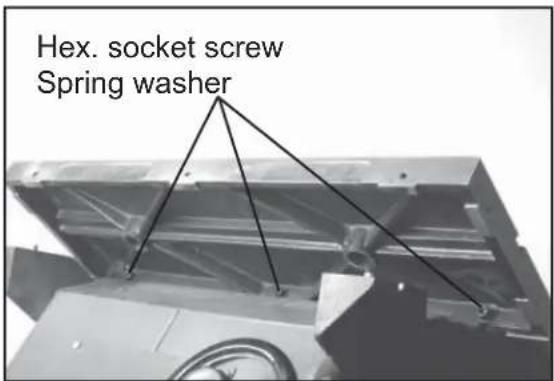
Figure 1

Figure 2
natural_image
Hand using a hammer to cut a metal component with holes (no text or symbols visible)Figure 3
natural_image
Mechanical assembly with a metal frame and circular components, no visible text or symbolsFigure 4
Assembly
Assembling the Optional Sliding Table
Please refer to the Sliding Table Attachment manual located in the separate shipping carton for proper installation procedures.
Installing Front Fence Rail
- Identify the front rail (E), which is the larger "L" shaped bar with the countersunk mounting holes facing front.
NOTE: The front fence rail can be mounted differently depending on the use of the cast table wing or the sliding table attachment. When using the table wing the front fence rail should be installed as described below. Please refer to the Sliding Table Attachment manual for proper placement of the front fence rail. Figure 5. - Align the "L" shaped bar so the left notch (H) matches the miter slot on the left extension wing.
- Secure the front rail (E) to the table (G) and table wings (F) with five countersunk head screws (A). Tighten just enough to hold the rail next to the table but keep loose enough to allow height adjustment. Figure 6.
- When the Front Rail has been correctly positioned, tighten all mounting screws securely with the 5MM L wrench provided.
Rear Fence Rail Installation
- Identify the rear fence rail, which is the smaller "L" shaped bar. Place against the table and align as shown. Figure 7.
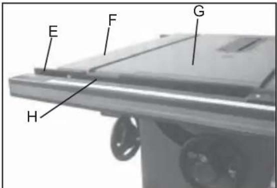
Figure 5

Figure 6
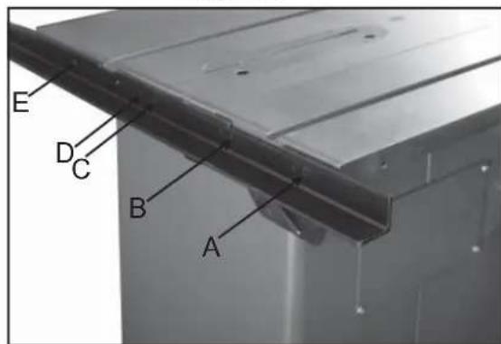
Figure 7
Assembly
Rear Fence Rail Installation Continued
NOTE: The rear fence rail can be mounted differently depending on the use of the cast table wing or the sliding table attachment. When using the table wing the rear fence rail should be installed as described below. Please refer to the Sliding Table Attachment manual for proper placement of the back fence rail.
-
Align the rear fence rail so the right notch matches the miter slot on the left extension wing. (A-Fig. 9)
-
Secure the rear fence rail to the tapped holes in the saw table and table wings with fi ve M8 hex head cap screws. Tighten screws securely with a 6MM L wrench. Figures 8&9.
Installing Fence to the Guide Bar
Lay the fence onto the guide bar. The lock lever has three functional positions as shown in Figure 10:
A. The upright position permits mounting and removal of fence from the saw.
B. The unlock position permits easy fence positioning.
C. The lower position locks the fence to the front rail.
Installing the Fence Scale
NOTE: The fence scale can be mounted differently depending on the use of the cast table wing or the sliding table attachment. When using the table wing the fence scale should be installed as described below. Please refer to the Sliding Table Attachment manual for proper placement of the fence scale.
- Lay the fence onto the guide bar and slide fence up against the saw blade. With the fence in the locked position, pull back 1/4" of the adhesive backing and slide the fence scale under the cursor.
- Line up the "zero" position on the fence scale with the line on the cursor. Figure 11.

Figure 8

natural_image
Close-up of a metal bracket with a labeled point A pointing to a surface (no other text or symbols visible)Figure 9
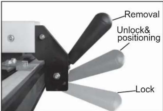
Figure 10
natural_image
Close-up of mechanical clamping mechanism with black and white components (no visible text or symbols)Figure 11
Assembly
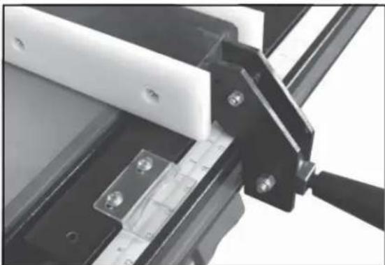
Leveling Fence to the Saw Table
-
View the fence from the left side of the saw (Figure 12). Look for the space between the table and the fence bottom to be equal along the entire length of the fence.
-
If the fence is highest at the rear of the table, lower the nylon pad at the rear of the fence using a 10MM wrench.
-
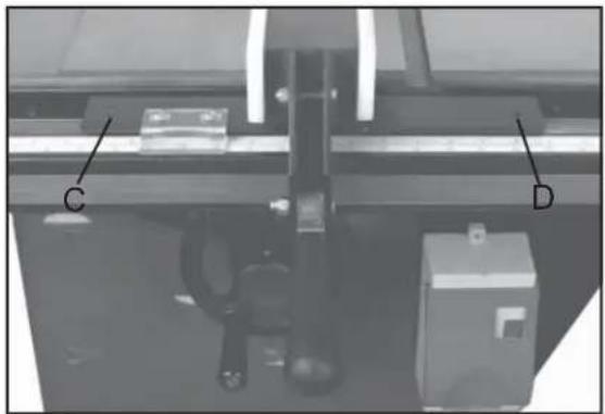
If the fence is highest at the front of the table, raise the two nylon pads on the front of the fence with a 4MM L wrench. Raise each side equally as it could cause the fence to be out of square with the table. (C,D, Fig. 13.)

Figure 12
natural_image
Mechanical assembly with labeled components C and D, no readable text or symbols beyond labelsFigure 13
Assembly
Adjusting Fence Parallel to the Miter Slot
- Place the fence next to the outside edge of the right miter slot and lock it.
- The fence should be even with the miter slot from front to back.
- If the fence is not even along the length of the miter slot, unlock the fence, remove it and turn upside down.
- Adjust one of the two set screws (A, Fig. 14) until the fence is even with the miter slot edge along its entire length when locked.
Squaring Fence 90° to the Table
- Place the fence on the saw table and lock it.
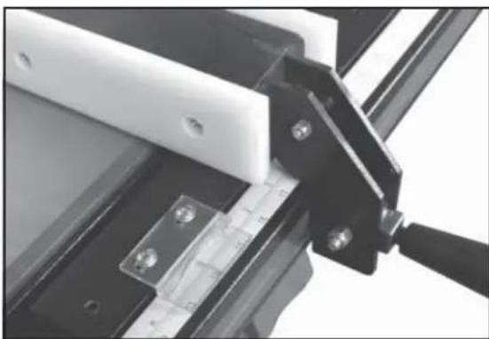
- Place a square (A, Fig. 15) on the table next to the fence. The fence should be 90^ to the table.
- If adjustment is necessary, unlock the fence, and turn one of the two nylon adjustment screws (B, Fig. 15) until the fence is 90^ to the table.
- Lock the fence and check the adjustment again.
Fence Cursor Adjustment
- Lock the fence down 3" from the saw blade.
- Measure off of the blade and check if it correct with fence scale.
- If adjustment is needed loosen the two screws on the cursor and align as needed. Tighten screws
- If further adjustment is needed loosen the mounting bolts to the guide tube and shift it left to right as needed. Figure 16.

natural_image
Close-up of a mechanical setup with two labeled points A, mounted on a metal frame and ruler (no text or symbols beyond labels)Figure 14
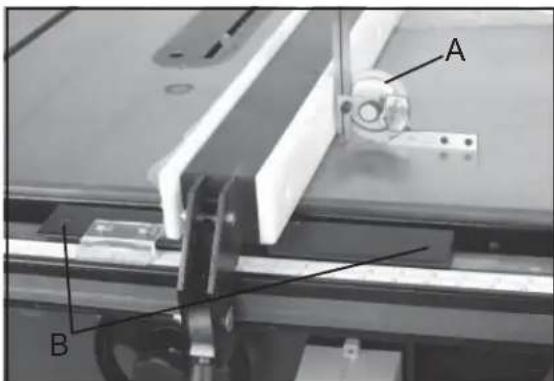
Figure 15
natural_image
Close-up of mechanical clamping mechanism with black and white components (no visible text or symbols)Figure 16
Assembly
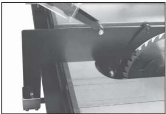
Blade Guard and Splitter Installation
-
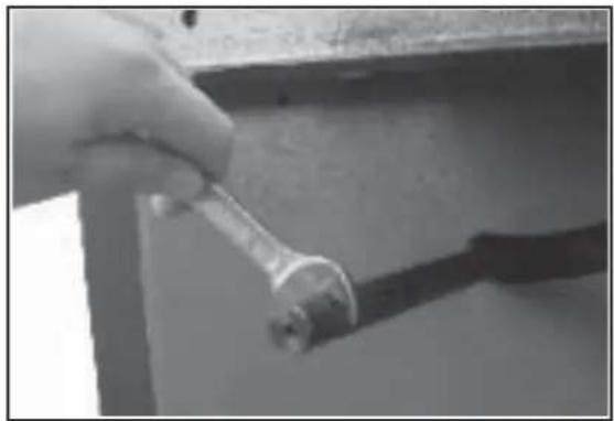
Remove table insert and raise the saw blade, then loosen the hex head cap screw (A, Fig.17) located on the rear table trunnion assembly. Figure 17.
-
Install guard post through slot at rear of saw and into the hole in the trunnion. Fasten into place with one 8MM square nut (B, Fig.17) with 14MM wrench. Figure 18.
-
The spillter support bracket must be installed on to guard post as shown. Figure 19.
-
Slide the guard into place and tighten the hex head cap screw on the rear trunnion assembly and tighten the nut on the splitter support bracket. Figure 20.

Figure 17
natural_image
Close-up of a hand holding a wrench against a wall, with no visible text or symbolsFigure 18

natural_image
Close-up of a hand holding a small mechanical component, possibly a switch or connector (no visible text or symbols)Figure 19
natural_image
Close-up of a mechanical device with a metallic gear and lever, no visible text or symbolsFigure 20
Assembly
Blade Installation and Removal
WARNING! Please disconnect saw from the power source. Make sure to use caution while work with or around saw blade.
- Raise the blade arbor and make sure the arbor is at the zero degree position.
- To install during initial assembly, remove the arbor nut (A, Fig. 21) and flange (B, Fig. 21) from arbor.
- Place blade (C, Fig. 21) on arbor shaft making sure teeth point down at the front of the saw. Replace flange and arbor nut, tightening arbor nut toward the rear of the machine.
- To remove the blade place a wood scrap in the blade's teeth at the front of the machine. Hold the block of wood in such a way that if it slips or the blade turns, your hand will not contact the blade. Loosen arbor nut by pulling wrench toward the front of the machine.(Fig. 22)
- Reverse operation to remove blade.
Leveling the Blade Insert
- Adjust table insert (A, Fig. 23) flush with table by turning four leveling screws (B, Fig. 23).
- Use a straight edge (C, Fig. 23) to make sure the insert is flush with the table.
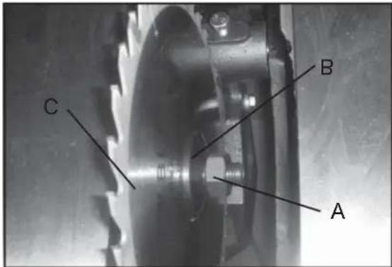
Figure 21
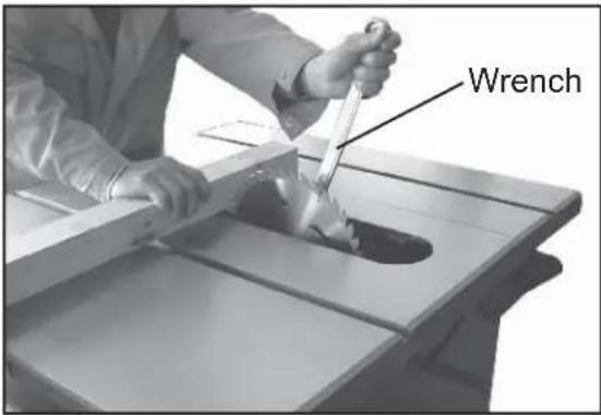
Figure 22
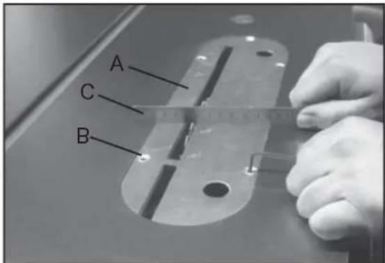
Figure 23
Operation
Raising and Tilting the Saw Blade
- To raise or lower the saw blade, loosen the lock knob (A, Fig. 24) and turn the handwheel (B, Fig. 24) on the saw front until desired height is reached. Tighten lock knob. The blade should be adjusted 1/8" to 1/4" above the top surface of the material being cut.
- To tilt the saw blade, loosen the lock knob (C, Fig. 24) found on the left side of the table saw and turn handwheel (D, Fig. 24) until desired angle is obtained, then tighten lock knob.
Switch Operation
NOTE: The switch has a built in safety feature and will not restart if the breaker is tripped.
1.) To start the saw, depress the green button at the top of the switch (A, Fig. 25).
2.) To shut the saw off, hit the large stop paddle with your hand. For hands free operation, you can bump the large stop paddle with your knee (B, Fig. 25).
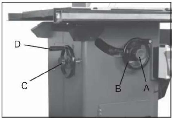
Figure 24
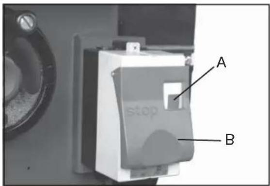
Figure 25
Maintenance
Caution! BEFORE CLEANING OR CARRYING OUT MAINTENANCE WORK, DISCONNECT THE MACHINE FROM THE POWER SOURCE (WALL SOCKET). NEVER USE WATER OR OTHER LIQUIDS TO CLEAN THE MACHINE. USE A BRUSH. REGULAR MAINTENANCE OF THE MACHINE WILL PREVENT UNNECESSARY PROBLEMS.
Keep the table clean to ensure accurate cutting.
Keep the outside of the machine clean to ensure accurate operation of all moving parts and prevent excessive wear.
Keep the ventilation slots of the motor clean to prevent it from overheating.
Keep the inside (near the saw blade, etc.) clean to prevent accumulation of dust.
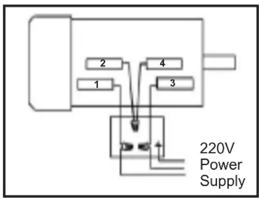
Wiring Diagram
WARNING! This machine must be grounded.
Replacement of the power supply cable should only be done by a qualified electrician.
Troubleshooting
WARNING!
FOR YOUR OWN SAFETY, ALWAYS TURN OFF AND UNPLUG THE MACHINE BEFORE CARRYING OUT ANY TROUBLESHOOTING.
| SYMPTOM | POSSIBLE CAUSE | CORRECTIVE ACTION |
| Votor will not start. | Low voltage. Open circuit in motor or loose connections. | Check power line for proper voltage. Inspect a lead connections on motor for loose or open connections. |
| Votor will not start; tuses or circuit breakers blow. | Short circuit in line: card or ping. Short circuit In motor or loose connections. Incorrect fuses or circuit breakers in power line. | Inspect card or plug for damaged insulation and shorted wires. Inspect aI connections on motor for loose or shored terminals or wear insulation. Instal correct fuses or circuit breakers |
| Votor over-lease. | Motor over oaded. A: circulation ilough the inc or restated. | Fledt ce load on motor. Clean cut motor to provide normal a circulation. |
| Votor stall (resulting in open bases or trupper circuit). | Short circuit in motor or loose connections. Low voltage. Incorrect fuses or circuit breakers in power line. Motor over ordered. | Inspect connections on motor for loose or stredes terminals or worn insulation. Correct the low so large conditions. Instal correct fuses or circuit breakers Reduce load on motor. |
| Machine slows when operating. Blade is not square wither slot or fence is not square to blade. | Applying co reach pressure to workpiece. Bells loose. Blade is w: ped. Table cap is not parallel to blade. Fence is not scale to blade. | Feed workpiece: d weaker. Tighten table. Replace blade. Move:able parallel to blade. Make fence: parallel to blade. |
| Force hits table too when sliding on to the table. | Front rail is but led too low on table. Rear rail is bolted too low on the table. | Base front rail. Base rear rail. |
| Blade does not reach 90°. Blade hits next at 45° | 90° stop bolt is cut of adjustment. Pointer bracket is fixing before the blade reaches 90°. Hole in reset is inadequate. Table out of alignment. Blade position is incorrect. | Adjust 90° step bolt. Tile down the right side of the pinier bracket until the blade can reach 90°. File: or mill the hole in the insert. Align table. Adjust: base position. |
For parts or technical questions contact: techsupport@rikontools.com or 877-884-5167.
Electrical Requirements
In the event of a malfunction or breakdown, grounding provides a path of least resistance for electric current to reduce the risk of electric shock. This tool is equipped with an electric cord having an equipment-grounding conductor and a grounding plug. The plug must be plugged into a matching outlet that is properly installed and grounded in accordance with all local codes and ordinances.
Do not modify the plug provided. If it will not fit the outlet, have the proper outlet installed by a qualified electrician.
Improper connection of the equipment-grounding conductor can result in a risk of electric shock. The conductor, with insulation having an outer surface that is green with or without yellow stripes, is the equipment-grounding conductor. If repair or replacement of the electric cord or plug is necessary, do not connect the equipment-grounding conductor to a live terminal.
Check with a qualified electrician or service personnel if the grounding instructions are not completely understood, or if in doubt as to whether the tool is properly grounded.
Use only three wire extension cords that have three-prong grounding plugs and three-pole receptacles that accept the tool's plug.*
Repair or replace a damaged or worn cord immediately.
This tool is intended for use on a circuit that has an outlet that looks the one illustrated in Figure A below. The tool has a grounding plug that looks like the grounding plug as illustrated in Figure A below.
* Canadian electrical codes require extension cords to be certified SJT type or better.
** Use of an adapter in Canada is not acceptable.

Figure A
Parts Diagram

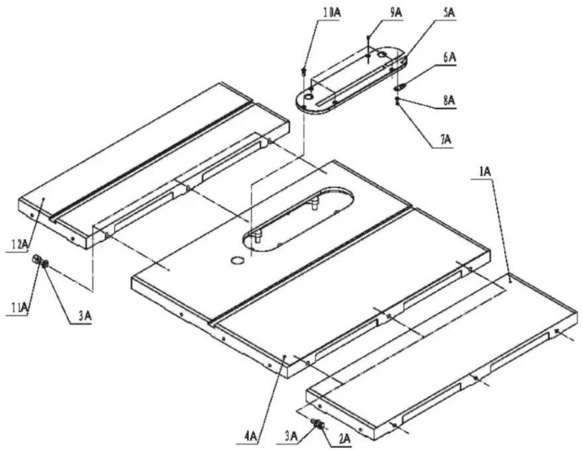
Parts Diagram

Parts List
| Key No. | Part No. | Description | Key No. | Part No. | Description |
| 1A | 1-JL84010002 | Extension wing | 1B | 1-JL84021000 | Cabinet |
| 2A | 1-M10X30GB5783Z | Hex bolt M10X30 | 2B | 1-JL84020002 | Cover plate |
| 3A | 1-WSH10GB95Z | Washer 10 | 3B | 1-M6X10GB818Z | Set screw M6X10 |
| 4A | 1-JL84010001 | Table | 4B | 1-WSH6GB95Z | Washer 6 |
| 5A | 1-JL84010003 | Table insert | 5B | 1-JL84020003 | Hook |
| 6A | 1-JL84010005 | Spring plate | 6B | 1-M6GB6170Z | Nut M6 |
| 7A | 1-M4X6GB818Z | Set screw M4X6 | 7B | 1-JL84020006 | Cover plate II |
| 8A | 1-WSH4GB95Z | Washer 4 | 8B | 1-M5X10GB819Z | Screw M5X10 |
| 9A | 1-M6X8GB77B | Set screw M6X8 | 9B | 1-WSH7GB97D1Z | Washer 7 |
| 10A | 1-M6X16GB819B | Set screw M6X16 | 10B | 1-M5GB923Z | Nut M5 |
| 11A | 1-M10X30GB70Z | Hex bolt M10X30 | 11B | 1-JL84020001 | Micro-adjusting bracket |
| 12A | 1-JL84010002A | Extension wing II | 12B | 1-M6X25GB5783Z | Hex bolt M6X25 |
| 13A | 1-JL84091000 | Guard | 13B | 1-JL91042100 | Locking bar assembly |
| 14A | 1-M10GB39Z | Square nut M10 | 14B | 1-JL84020004 | Support bracket |
| 15A | 1-WSH10GB95Z | Washer 10 | 15B | 1-M8X16GB5781Z | Hex bolt M8X16 |
| 16A | 1-JL84090001 | Shaft | 16B | 1-WSH8GB95Z | Washer 8 |
| 17A | 1-M5X20GB70Z | Set screw M5X20 | 17B | 1-WSH8GB93Z | Washer 8 |
| 18A | 1-JL84090002 | Lower blade guard bracket | 18B | 1-M8GB6170Z | Nut M8 |
| 19A | 1-JL84090003 | Upper blade guard bracket | 19B | 1-JL84022000 | Motor cover |
| 20A | 1-M5GB6170Z | Nut M5 | 20B | 1-M8X65GB5781Z | Hex bolt M8X65 |
| 21A | 1-M5X10GB70Z | Bolt M5X10 | 21B | 1-M6X20GB5783Z | Hex bolt M6X20 |
| 22A | 1-WSH5GB97D1Z | Washer 5 | 22B | 1-JL84120001 | RIKON label |
Parts Diagram
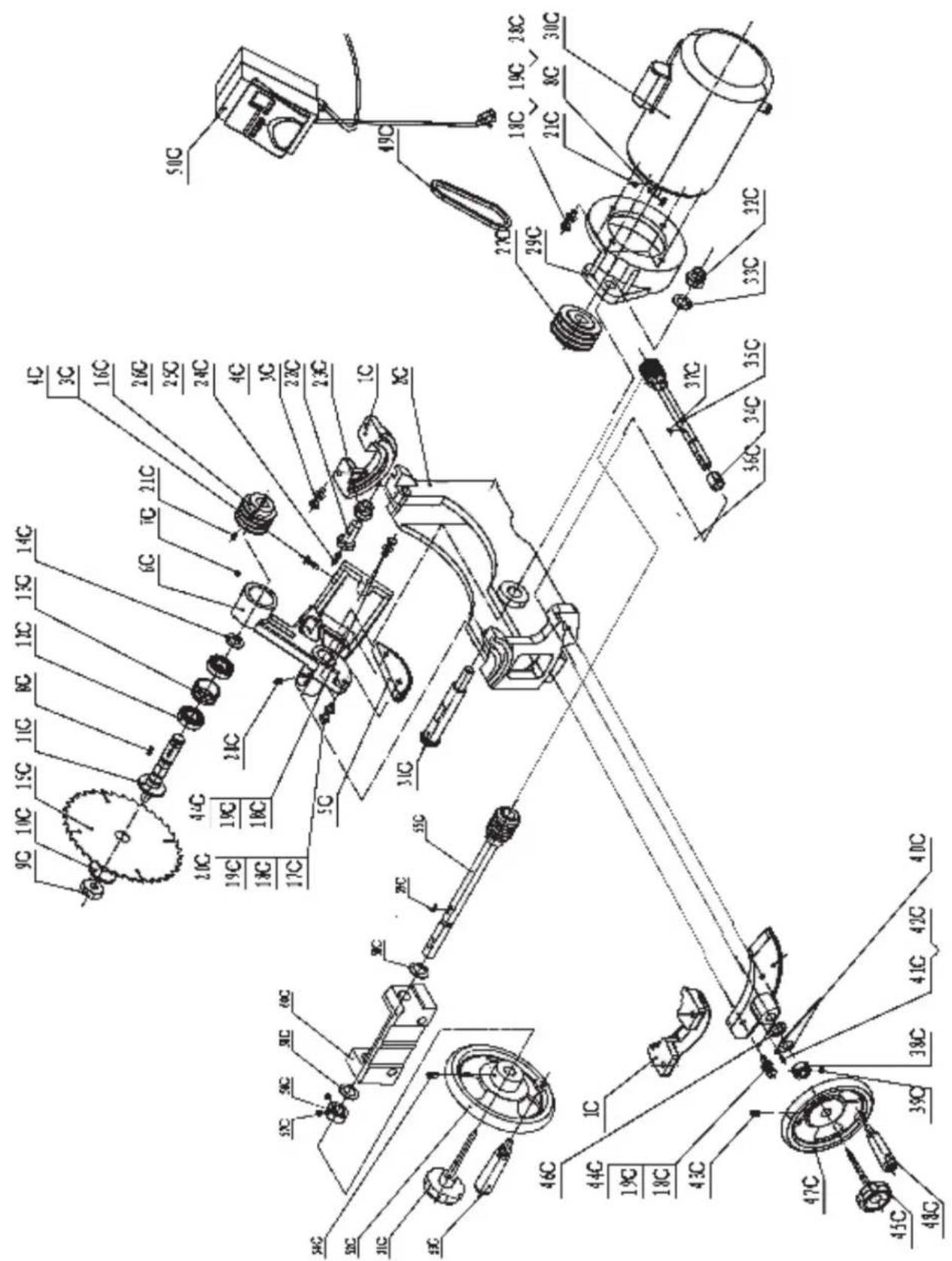
Parts List
| Key No. | Part No. | Description | Key Part No. No. | Description |
| 1C | 1-JL84040002 | Trunnion bracket | 31C 1-JL84040003 | Shaft |
| 2C | 1-JL84040001 | Trunnion | 32C 1-M20GB889D1Z | Locking nut M20 |
| 3C | 1-M8X25GB5783Z | Hex bolt M8X25 | 33C 1-WSH20GB95Z | Washer 20 |
| 4C | 1-M8GB6170Z | Nut M8 | 34C 1-JL84040005 | Collar |
| 5C | 1-JL84042003 | Turbine | 35C 1-JL84041000 | Worm shaft assembly |
| 6C | 1-JL84042001 | Arbor bracket | 36C 1-JL84040004 | Turbine II |
| 7C | 1-M10X10GB77B | Set screw M10X10 | 37C 1-PIN5X19GB1099 | Pin 5X19 |
| 8C | 1-PIN6X32GB1096 | Pin 6X32 | 38C 1-JL84030002 | Collar |
| 9C | 1-JL84042102 | Arbor nut | 39C 1-M8X8GB77Z | Set screw M8X8 |
| 10C | 1-JL84042103 | Arbor fl ange | 40C 1-JL84040006 | Pointer |
| 11C | 1-JL84042101 | Arbor with fl ange | 41C 1-M4X8GB818Z | Screw M4X8 |
| 12C | 1-BRG6205GB276 | Ball bearing | 42C 1-WSH4GB95Z | Washer 4 |
| 13C | 1-JL84042104 | Bearing load spacer | 43C 1-M8X16GB80B | Set screw M8X16 |
| 14C | 1-CLP25GB894D1 | Retaining ring | 44C 1-M10X35GB5783Z | Hex bolt M10X35 |
| 15C | 1-JL84042004 | Blade | 45C 1-JL84030003 | Lock knob |
| 16C | 1-JL84042002 | Arbor pulley | 46C 1-JL50000005 | Washer plate |
| 17C | 1-M10X40GB5781Z | Hex bolt M10X40 | 47C 1-JL84032000(1) | Handwheel |
| 18C | 1-WSH10GB95Z | Washer 10 | 48C 1-JL84032000(2) | Hand wheel handle |
| 19C | 1-WSH10GB93Z | Washer 10 | 49C 1-JL84040007 | V-belt |
| 20C | 1-M10X50GB5781Z | Hex bolt M10X50 | 50C 1-HNPB-18K | Magnetic switch |
| 21C | 1-M8X12GB77B | Set screw M8X12 | 51C 1-JL84030003 | Lock knob |
| 22C | 1-JL84043001 | Adjusting bolt for guard | 52C 1-JL84032000(1) | Handwheel |
| 23C | 1-JL84043002 | Adjusting nut for guard | 53C 1-JL84032000(2) | Hand wheel handle |
| 24C | 1-WSH6GB96Z | Washer 6 | 54C 1-M8X16GB80B | Set screw M8X16 |
| 25C | 1-WSH6GB93Z | Spring washer 6 | 55C 1-JL84031000 | Worm shaft assembly II |
| 26C | 1-M6X10GB70D1Z | Screw M6X10 | 56C 1-JL84030002 | Collar |
| 27C | 1-JL84044001 | Motor pulley | 57C 1-M8X8GB77Z | Set screw M8X8 |
| 28C | 1-M10X30GB5783Z | Hex bolt M10X30 | 58C 1-JL50000005 | Washer plate |
| 29C | 1-JL84044003 | Motor mounting bracket | 59C 1-PIN5X19GB1099 | Pin 5X19 |
| 30C | 1-G1123692 | Motor | 60C 1-JL84030001 | Support bracket |
Parts Diagram

Parts List
Key Part No. Description
No.
| 1D | 1-JL84051200 | Lock handle assembly |
| 2D | 1-PIN5X30GB879B | Pin 5X30 |
| 3D | 1-JL84051100 | Fence bracket assembly |
| 4D | 1-M8X45GB12Z | Carriage bolt M8X45 |
| 5D | 1-M8GB889Z | Nut M8 |
| 6D | 1-JL84051003 | Magnifi er |
| 7D | 1-M5X8GB818Z | Screw M5X8 |
| 8D | 1-JL84051008 | Frication plate |
| 9D | 1-M8X8GB77B | Screw M8X8 |
| 10D | 1-M6X40GB5783Z | Hex bolt M6X40 |
| 11D | 1-M6GB889Z | Locking nut M6 |
| 12D | 1-JL84051001 | Bracket |
| 13D | 1-JL84051004 | Torsion spring |
| 14D | 1-JL84051005 | Adjusting screw |
| 15D | 1-JL84051007 | Rear support bracket |
| 16D | 1-M6GB6170Z | Nut M6 |
| 17D | 1-M6X16GB818Z | Pan head screw M6X16 |
| 18D | 1-JL84051002 | Defend plate |
| 19D | 1-M6X12GB5783Z | Hex bolt M6X12 |
| 20D | 1-JL84050002 | Front fence rail |
| 21D | 1-JL84051006 | Tube cap |
| 22D | 1-JL84050001 | Front fence rail support |
| 23D | 1-JL84050003 | Rear fence support |
RIKON POWER TOOLS
2-Year Limited Warranty
RIKON Power Tools/Richen Enterprise, Inc. (“Seller”) warrants to only the original retail consumer/purchaser of our products that each product be free from defects in materials and workmanship for a period of two (2) years from the date the product was purchased at retail. This warranty may not be transferred.
This warranty does not apply to defects due directly or indirectly to misuse, abuse, negligence, accidents, repairs, alterations, lack of maintenance or normal wear and tear. Under no circumstances will Seller be liable for incidental or consequential damages resulting from defective products. All other warranties, expressed or implied, whether of merchantability, fitness for purpose, or otherwise are expressly disclaimed by Seller. This warranty does not cover products used for commercial, industrial or educational purposes.
This limited warranty does not apply to accessory items such as blades, drill bits, sanding discs or belts and other related items.
Seller shall in no event be liable for death, injuries to persons or property, or for incidental, contingent, special, or consequential damages arising from the use of our products.
To take advantage of this warranty proof of purchase documentation, which includes date of purchase and an explanation of the complaint, must be provided.
The Seller reserves the right to effect at any time, without prior notice, those alterations to parts, fi ttings, and accessory equipment which they may deem necessary for any reason whatsoever.
To take advantage of this warranty, please fill out the enclosed warranty card and send it to: RIKON Warranty 110 Cummings Park Woburn, MA 01801
The card must be entirely completed in order for it to be valid. If you have any questions please contact us at 877-884-5167 or warranty@rikontools.com.
BIKON POWER TOOLS
For more information:
110 Cummings Park
Woburn, MA 01801
877-884-5167/781-933-8400
techsupport@rikontools.com
www.rikontools.com


- Operator Safety: Required Reading
- General Safety Warnings
- DANGER
- ALWAYS GROUND ALL TOOLS.
- ALWAYS AVOID DANGEROUS ENVIRONMENTS.
- ALWAYS REMOVE THE ADJUSTING KEYS AND WRENCHES FROM TOOLS AFTER USE.
- ▲ DANGER
- ALWAYS KEEP VISITORS AWAY FROM RUNNING MACHINES.
- ALWAYS MAKE THE WORKSHOP CHILDPROOF.
- ALWAYS WEAR PROPER APPAREL.
- NEVER OVERREACH.
- Table Saw Safety Rules
- SAVE THESE INSTRUCTIONS.
- Refer to them often.
- Table of Contents
- Content of Package
- Unpacking and Checking Contents
- Loose Parts
- Box #1
- Loose Parts Continued
- Getting To Know Your Table Saw
- Assembly
- Installing the Right Table Wing
- Installing the Optional Left Wing
- Assembling the Optional Sliding Table
- Installing Front Fence Rail
- Rear Fence Rail Installation
- Rear Fence Rail Installation Continued
- Installing Fence to the Guide Bar
- Installing the Fence Scale
- Leveling Fence to the Saw Table
- Adjusting Fence Parallel to the Miter Slot
- Squaring Fence 90° to the Table
- Fence Cursor Adjustment
- Blade Guard and Splitter Installation
- Blade Installation and Removal
- Leveling the Blade Insert
- Operation
- Raising and Tilting the Saw Blade
- Switch Operation
- Maintenance
- Wiring Diagram
- WARNING! This machine must be grounded.
- Troubleshooting
- WARNING!
- Electrical Requirements
- Parts Diagram
- Parts List
- Key Part No. Description
- RIKON POWER TOOLS
- 2-Year Limited Warranty
- BIKON POWER TOOLS
Brand : RIKON
Model : 10-110
Category : Saw