CLXI-1MC4 - Controller Crestron - Free user manual and instructions
Find the device manual for free CLXI-1MC4 Crestron in PDF.

User questions about CLXI-1MC4 Crestron
0 question about this device. Answer the ones you know or ask your own.
Ask a new question about this device
Download the instructions for your Controller in PDF format for free! Find your manual CLXI-1MC4 - Crestron and take your electronic device back in hand. On this page are published all the documents necessary for the use of your device. CLXI-1MC4 by Crestron.
USER MANUAL CLXI-1MC4 Crestron
The Crestron ^® 1-Feed, 4-Motor Terminal Block and Module (CLTI-1MC4 and CLXI-1MC4, respectively), are considered a single entity and must be used together. They ship separately to permit termination of the field wiring to the CLTI-1MC4 prior to installation of the CLXI-1MC4, as described in this guide. They can be mounted in any Crestron Automation Enclosure (CAEN or CAENIB-Series Enclosures). The terminal block is designed to terminate the circuit feed (LINE and NEUTRAL) and distribute the controlled circuits (LOAD) to the motors. The module connects to the terminal block and performs control of four bi-directional motors. The maximum load is 8 amps (1 HP) for any controlled circuit, limited to 13 amps total per module. The unit requires 230VAC 50 Hz, 1 phase input voltage. An oversize heat sink dissipates heat efficiently. There are LEDs on the module to indicate communication to a Cresnet ^® network, input power to the module, and output power to the load.
Installation
Terminal block and module must be mounted into a Crestron Automation Enclosure by a licensed electrician, in accordance with all national and local codes.
CAUTION: This equipment is for indoor use only and needs to be air-cooled. Mount in a well-ventilated area. The ambient temperature must be 0^ C to 40^ C ( 32^ F to 104^ F). The relative humidity must be 0% to 90% (non-condensing).
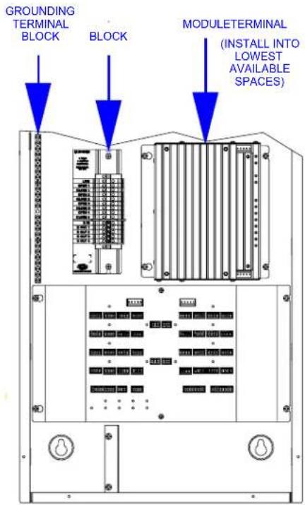
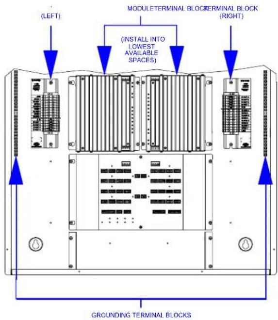
Terminal blocks are installed along the left side of single-wide enclosures and along the outside edges (left and right sides) of double-wide enclosures. Modules are installed along the right side of single-wide enclosures and side-by-side in the center of double-wide enclosures. When installing modules and terminal blocks in a double-wide enclosure, be sure to invert units on the right side so that they can be properly wired. Refer to the illustrations shown in the next column when considering the location of terminal blocks and modules within an enclosure.
NOTE: Modules and terminal blocks must be installed into the lowest available spaces and continue toward the top of the enclosure.
Terminal Block & Module Locations (Single-wide Enclosure)
Terminal Block & Module Locations (Double-wide Enclosure)
Terminal Block Installation and Field Wiring
NOTE: To install a CLTIBN Circuit Breaker Terminal Block, refer to the latest version of the CLTIBN Installation Guide (Doc. 6561) which can be downloaded from the Crestron website (www.crestron.com/manuals).
NOTE: Both left-side and right-side adhesive wiring labels are provided. The left-side labels are used in both single and double-wide enclosures. The right-side labels are only used in double-wide enclosures.
- Remove the backing from the left or right adhesive wiring label.
- Apply the adhesive label by aligning the holes in the label with the appropriate holes on the Crestron Automation Enclosure where the terminal block is to be mounted. For information on mounting locations, refer to the latest version of the CAEN Installation Guide (Doc. 5940) or the CAENIB Installation Guide (Doc. 6562). The wiring label lies beneath the terminal block as shown in the two wiring diagrams on this page.
- Use the two supplied self-tapping pan Phillips screws (8B x 14 -inch (6 mm) length) to secure the terminal block to the Crestron Automation Enclosure.
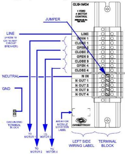
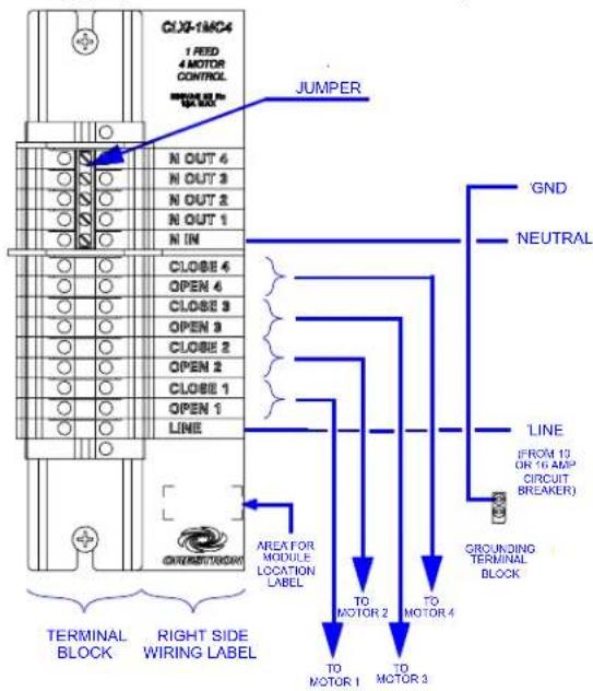
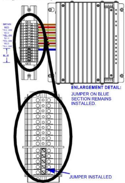
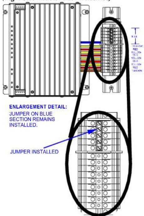
CAUTION: The jumper on the blue section of the terminal block ties the neutral in to the neutral outs. This jumper should never be removed.
NOTE: Use copper conductors only – rated 75°C.
- With the circuit breaker turned off, connect the circuit feed (LINE and NEUTRAL) and controlled circuit (LOAD) wires to the terminal block per the markings provided on the wiring label (as shown in the diagrams on this page). Terminal blocks accept one 2.5 - 6.0 mm² wire. Wires should be stripped to 12 mm. Tighten terminal blocks to 1 Nm.
NOTE: Only one motor may be wired per circuit.
- Grounding terminal blocks are available in the cabinet for termination of ground wires. Tighten to 4 Nm (2.5 - 6.0 mm ^2 ), 4.5 Nm (10.0 mm ^2 ), or 5.1 Nm (16 - 25 mm ^2 ).
- Test the circuit for electrical faults by connecting LINE to OPEN 1. Switch on the circuit breaker and check that it does not trip and that the load connected to OPEN 1 is receiving power. Switch off the circuit breaker, remove the connection
between LINE and OPEN 1, and repeat this step for CLOSE 1 and then sequentially for each OPEN and CLOSE motor connection.
NOTE: If installing in a CAENIB, complete the installation with a CAENIB-BP Blank Plate. Refer to the latest version of the CAENIB-BP Installation Guide (Doc. 6563) for details.
Wiring Diagram of the Terminal Block to the Feed and Load(s) (Single-wide and Left Side Double-wide Enclosures)
Wiring Diagram of the Terminal Block to the Feed and Load(s) (Right Side Double-wide Enclosures)
Module Installation
CAUTION: Module contains electrostatic sensitive devices (ESDs); unit must be handled from metal chassis – do not touch PC board or components.
NOTE: Modules are to be installed after enclosure has been completely wired. Refer to the terminal block installation procedure on page 2 for details.
- Use the four supplied self-tapping pan Phillips screws (8B x ¼-inch (6 mm) length) to secure the module to the enclosure.
- As shown in the wiring diagrams (next column), connect the wires from the module to the terminal block. Each wire exits the module directly in line with, and is the same color as, the terminal to which it should be connected. Wires are pre-stripped to 12 mm. Tighten to 1 Nm.
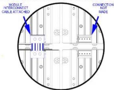
- If the module is being installed above another module within the enclosure, attach the supplied module interconnect cable between the two modules. The illustration below depicts the area within a double-wide enclosure where the corners of four modules meet.
NOTE: One wire on the module interconnect cable may be a different color from the rest. The color has no bearing on its orientation during installation.
Use Module Interconnect Cable to Wire Module to Module
- Turn on the circuit breaker and verify that the green PWR LED on the module lights and the breaker does not trip.
Wiring Diagram of the Terminal Block to the Module (Single-wide and Left Side Double-wide Enclosures)
Wiring Diagram of the Terminal Block to the Module (Right Side Double-wide Enclosures)
NOTE: Power must be supplied to LINE for the module to communicate with the control system or for any of the circuits to operate.
Testing
If the program is not running yet, loads can be tested by using Local Mode. Use Local Mode to verify that each load is connected to the proper output on the modules.
- Press the SETUP button momentarily (less than three seconds) to enter Local Mode. The SETUP LED and output LED 1 (O) illuminate and power is applied to the load connected to the OPEN 1 output for one second.
- Press the SETUP button again to apply power to the CLOSE 1 output for one second. Output LED 1 (C) will illuminate for one second.
- Press the SETUP button again for each output.
- Press the SETUP button once more to turn off all outputs and LEDs and exit Local Mode.
Industry Compliance
As of the date of manufacture this device has been tested and found to comply with specifications for CE marking.

Reference Documents
The latest version of all documents mentioned within the guide can be obtained from the Crestron website (http://www.crestron.com/manuals). This link will provide a list of product manuals arranged in alphabetical order by model number.
List of Related Reference Documents
| DOCUMENT TITLE |
| CAEN Automation Enclosures |
| CAENIB Automation Enclosures |
| CAENIB-BP Blank Plate for CAENIB |
| CLTIBN Circuit Breaker Terminal Block |
Further Inquiries
If you cannot locate specific information or have questions after reviewing this guide, please take advantage of Crestron's award winning customer service team by calling the Crestron corporate headquarters at 1-888-CRESTRON [1-888-273-7876]. For assistance in your local time zone, refer to the Crestron website (www.crestron.com/offices) for a listing of Crestron worldwide offices.
You can also log onto the online help section of the Crestron website (www.crestron.com/onlinhelp) to ask questions about Crestron products. First-time users will need to establish a user account to fully benefit from all available features.
Return and Warranty Policies
Merchandise Returns / Repair Service
- No merchandise may be returned for credit, exchange or service without prior authorization from CRESTRON. To obtain warranty service for CRESTRON products, contact an authorized CRESTRON dealer. Only authorized CRESTRON dealers may contact the factory and request an RMA (Return Merchandise Authorization) number. Enclose a note specifying the nature of the problem, name and phone number of contact person, RMA number and return address.
- Products may be returned for credit, exchange or service with a CRESTRON Return Merchandise Authorization (RMA) number. Authorized returns must be shipped freight prepaid to CRESTRON, 6 Volvo Drive, Rockleigh, N.J. or its authorized subsidiaries, with RMA number clearly marked on the outside of all cartons. Shipments arriving freight collect or without an RMA number shall be subject to refusal. CRESTRON reserves the right in its sole and absolute discretion to charge a 15% restocking fee plus shipping costs on any products returned with an RMA.
- Return freight charges following repair of items under warranty shall be paid by CRESTRON, shipping by standard ground carrier. In the event repairs are found to be non-warranty, return freight costs shall be paid by the purchaser.
CRESTRON Limited Warranty
CRESTRON ELECTRONICS, Inc. warrants its products to be free from manufacturing defects in materials and workmanship under normal use for a period of three (3) years from the date of purchase from CRESTRON, with the following exceptions: disk drives and any other moving or rotating mechanical parts, pan/tilt heads and power supplies are covered for a period of one (1) year; touchscreen display and overlay components are covered for 90 days; batteries and incandescent lamps are not covered.
This warranty extends to products purchased directly from CRESTRON or an authorized CRESTRON dealer. Purchasers should inquire of the dealer regarding the nature and extent of the dealer's warranty, if any.
CRESTRON shall not be liable to honor the terms of this warranty if the product has been used in any application other than that for which it was intended or if it has been subjected to misuse, accidental damage, modification or improper installation procedures. Furthermore, this warranty does not cover any product that has had the serial number altered, defaced or removed.
This warranty shall be the sole and exclusive remedy to the original purchaser. In no event shall CRESTRON be liable for incidental or consequential damages of any kind (property or economic damages inclusive) arising from the sale or use of this equipment. CRESTRON is not liable for any claim made by a third party or made by the purchaser for a third party.
CRESTRON shall, at its option, repair or replace any product found defective, without charge for parts or labor. Repaired or replaced equipment and parts supplied under this warranty shall be covered only by the unexpired portion of the warranty.
Except as expressly set forth in this warranty, CRESTRON makes no other warranties, expressed or implied, nor authorizes any other party to offer any warranty, including any implied warranties of merchantability or fitness for a particular purpose. Any implied warranties that may be imposed by law are limited to the terms of this limited warranty. This warranty statement supersedes all previous warranties.
Trademark Information
All brand names, product names and trademarks are the sole property of their respective owners. Windows is a registered trademark of Microsoft Corporation. Windows95/98/Me/XP/Vista and WindowsNT/2000 are trademarks of Microsoft Corporation.
This page is intentionally left blank.