
Cine Follow Focus One - Camera accessory OConnor - Free user manual and instructions
Find the device manual for free Cine Follow Focus One OConnor in PDF.

| Type de produit | Cine lens follow focus system |
| Marque | OConnor |
| Modèle | Cine Follow Focus One (C1241-0001) |
| Dimensions (L×H×P) | 11 × 5.5 × 5.1 in (280 × 140 × 130 mm) |
| Poids (incl. main bridge, studio rod, handwheel) | 1.83 lb (0.83 kg) |
| Poids du volant | 0.73 lb (0.33 kg) |
| Dimensions du volant | ∅4 × 3.2 in (∅102 × 81 mm) |
| Ratio d’entraînement | 35:19 (1:1.84) |
| Diamètre max. de lentille | 182 mm |
| Compatibilité tiges caméra | Studio 15 ou 19 mm |
| Fixation de l’engrenage d’entraînement | Bras pivotant, coulisse à queue d’aronde, accouplement dentelé standard |
| Système d’accouplement | Module sans jeu (backlash‑free) |
| Contenu de la boîte | Volant studio CFF‑1 (grande poignée déportée), pont principal, tige studio |
| Entretien et nettoyage | Utiliser uniquement des détergents doux. Nettoyer avec un chiffon humide non pelucheux. Ne jamais utiliser de solvants ou nettoyants à base d’huile. |
| Sécurité | Ne pas tirer la caméra par le volant. Ne pas suspendre d’objets lourds sur le volant. Toujours démonter avant transport. Utiliser exclusivement des pièces OConnor. |
| Accessoires recommandés | Engrenages d’entraînement 43 dents (C1241‑1600), 35 dents (C1241‑1700), 50 dents (C1241‑1800), 60 dents (C1241‑1900). Pont pour tige studio (C1241‑1300). Volant double face (C1241‑1100 Cine, C1242‑1100 Photo). Extension volant 70 mm (C1241‑1500). Disque de marquage luminescent (C1241‑2117/1531). |
| Garantie | Voir conditions de garantie OConnor. |
| Réparabilité | Pièces détachées disponibles auprès des revendeurs agréés OConnor. |
Frequently Asked Questions - Cine Follow Focus One OConnor
User questions about Cine Follow Focus One OConnor
0 question about this device. Answer the ones you know or ask your own.
Ask a new question about this device
Download the instructions for your Camera accessory in PDF format for free! Find your manual Cine Follow Focus One - OConnor and take your electronic device back in hand. On this page are published all the documents necessary for the use of your device. Cine Follow Focus One by OConnor.
USER MANUAL Cine Follow Focus One OConnor
Copyright © 2011 The Vitec Group plc
All rights reserved throughout the world. No part of this document may be stored in a retrieval system, transmitted, copied or reproduced in any way, including, but not limited to, photocopy, photograph, magnetic or other record without the prior agreement and permission in writing from the Vitec Group plc.
Contents
Caution 2
The Cine Follow Focus One 4
Specification 5
In the box....6
Accessories 7
Components 9
Assembly
repositioning the lock levers....10
mounting the swing arm & drive gear.... 11
mounting the handwheel 12
mounting onto the camera rods 13
engaging the drive gear....14
markings discs & witness marker. 16
Dismounting 17
Storage 18
OConnor Offices worldwide....19
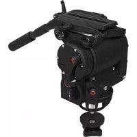
The Cine Follow Focus One

Specification
Cine Follow Focus One (C1241-0001)
Weight (incl. main bridge, studio rod, handwheel)....1.83 lbs (0.83 kg)
Weight of handwheel 0.73 lbs (0.33 kg)
Dimensions (WxHxD) 11 x 5.5 x 5.1 in. (280 x 140 x 130 mm)
Dimensions of Cine handwheel ....04 x 3.2 in. (∅102 x 81 mm)
Gear attachment
Positioning of driver gear....swing arm, dovetail slide
Driver gear coupling .... standard serrated star
Module coupling system .... backlash-free
Drive ratio 35:19 (1:1.84)
Lenses
Maximum lens diameter ....0182 mm
Rod system compatibility
for standard camera rods .... studio 15 / 19 mm
Specifications are subject to change without notice
In the box
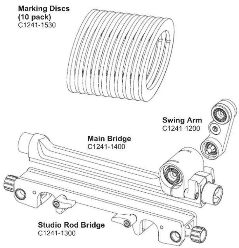

CFF-1 Studio Handwheel (full-size offset knob)
C1241-1100
Accessories
Drive Gears
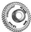
43 tooth
C1241-1600
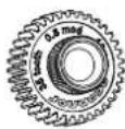
35 tooth
C1241-1700
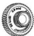
50 tooth
C1241-1800
60 tooth
C1241-1900
Matching OConnor accessories:
Studio rod bridge
C1241-1300 (depending on lens)
Handwheel (for double-sided use)
C1241-1100 (Cine)
C1242-1100 (Photo)
Handwheel extension (70 mm)
C1241-1500
"Glow-in-the-dark" marking disc
C1241-2117 (single disc, large)
C1241-1531 (10 pack, large)
| Part No. |  Drive Gear Drive Gear |  Lens Lens |
| C1241-1600 | Driver Gear 43 tooth 0.8M 6 mm face | Cine |
| C1241-1700 | Driver Gear 35 tooth 0.8M 10 mm face | Cine |
| C1241-1900 | Driver Gear 60 tooth 0.5M 7.5 mm face | Canon ENG focus |
| C1241-1800 | Driver Gear 50 tooth 0.6M 7.5 mm face | Fujinon ENG focus |
Caution
- DO NOT attempt to move the camera by pulling on the Cine Follow Focus One handwheel.
• DO NOT hang heavy items over the handwheel. - AVOID overtightening the drive gear onto the lens focus drive.
- ALWAYS use genuine OConnor parts and accessories with the Cine Follow Focus One.
- NEVER use solvents or oil-based cleaners to clean the Cine Follow Focus One. Use mild detergents only. Wipe surfaces with a damp, lint-free cloth.
• ALWAYS dismantle when not in use and before transporting.
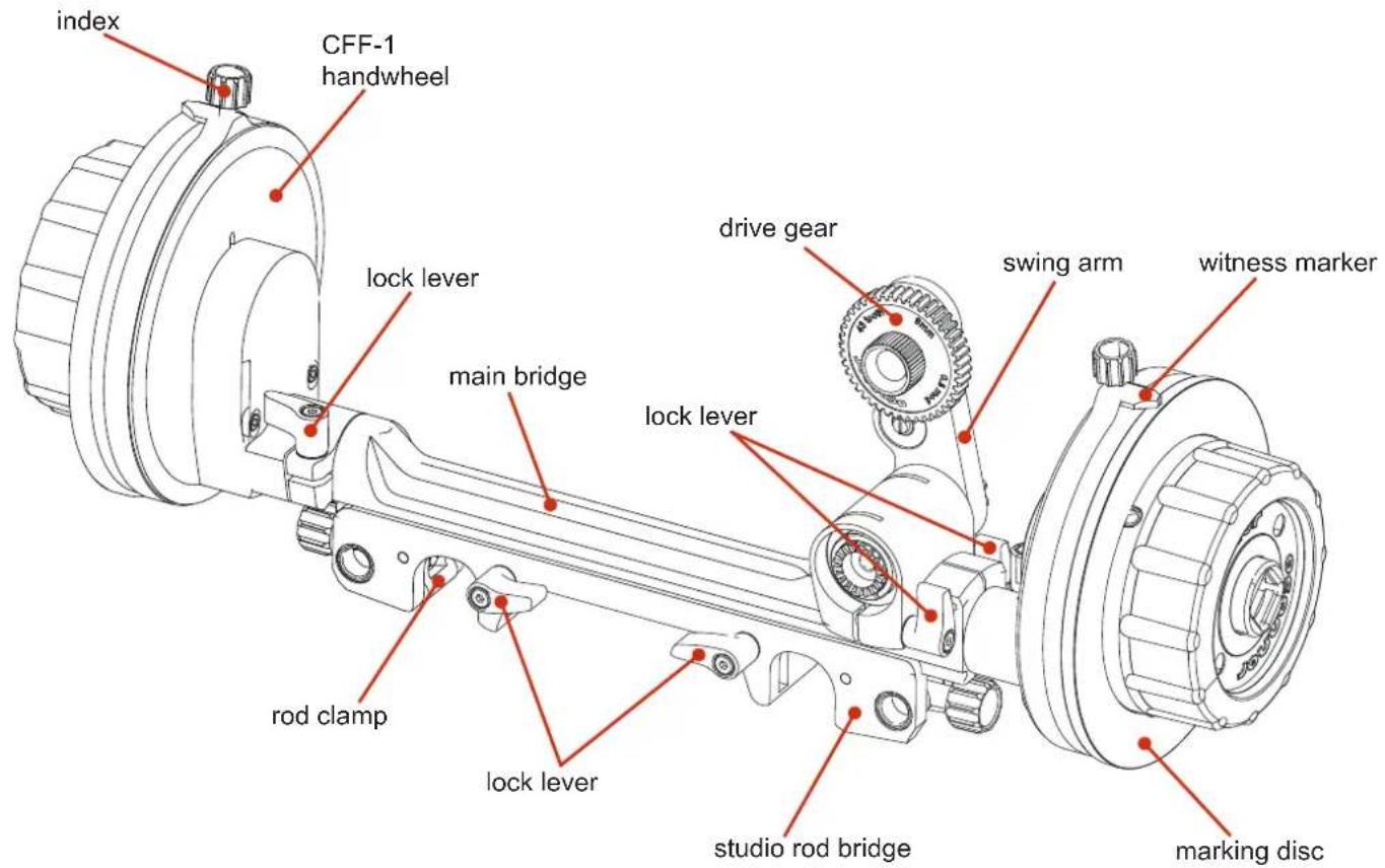
Components
repositioning the lock levers

To reposition the lock levers:
a

Pull the lock lever towards you.

b

Rotate the lock lever to the correct position.
2 Secure the studio rod bridge using the two lock levers.

When locked, the lock lever must not obscure the path of the camera rod.
C
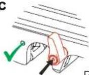
Push the lock lever to secure into position.
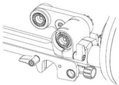
mounting the swing arm & drive gear

3 Ensure that the teeth on the swing arm and main bridge interlock. Firmly hold the top of the swing arm (where the drive gear fits) whilst tightening the knurled screw.
Note: The swing arm can be mounted on either side of the main bridge.
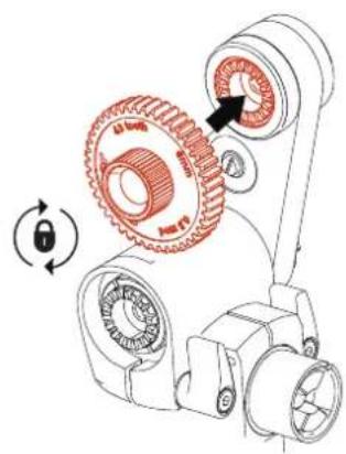
4 Select the correct gear for the lens in use. Ensure that the teeth on the drive gear and swing arm interlock. Secure by tightening the knurled screw on the drive gear.
Note: The drive gear can be mounted on either side of the swing arm.
mounting the handwheel
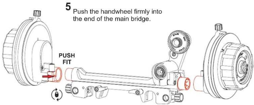
6
Hold the handwheel firmly in position at the end of the main bridge and secure using the lock lever.
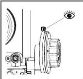
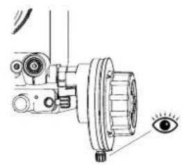
Important note:
Ensure that you can clearly see the witness marker. Mount the handwheel in either position.
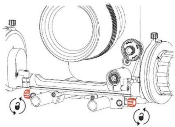
mounting onto camera rods
7
Place the Cine Follow Focus One onto the camera rods so that the drive gear is adjacent to the lens focus drive. Secure into position using the knurled screws at the end of the studio rod bridge.
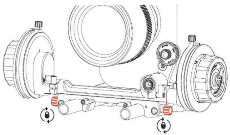
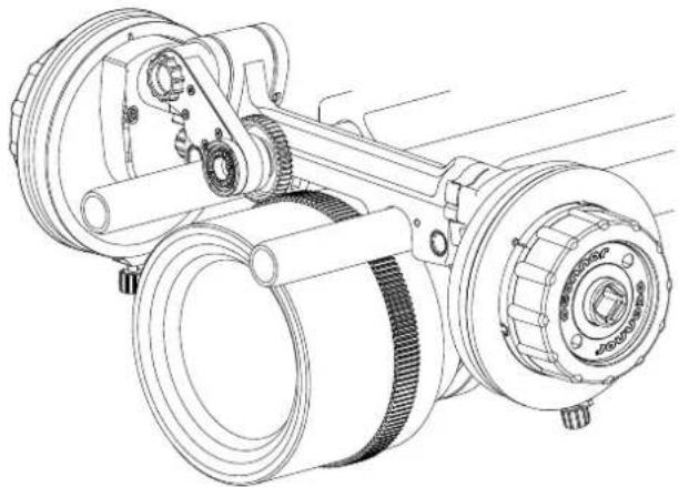
The Cine Follow Focus One can be mounted from camera rods suspended above the camera.
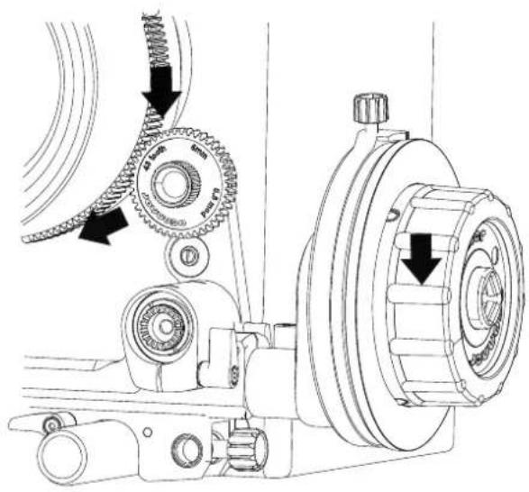
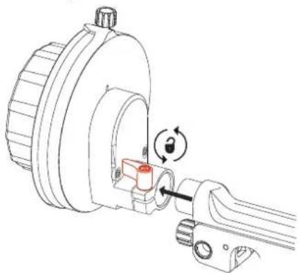
engaging the drive gear
8
Loosen the lock lever securing the swing arm in position.
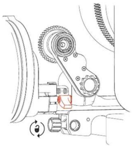
Note: If the swing arm is mounted on the back of the main bridge, as shown, turn the lock lever clockwise to loosen the swing arm. If the swing arm is mounted on the front of the main bridge, turn the lock lever counterclockwise to loosen the swing arm.
9
Position the swing arm, so that the drive gear engages with the lens focus drive. Secure the swing arm into position using the lock lever.
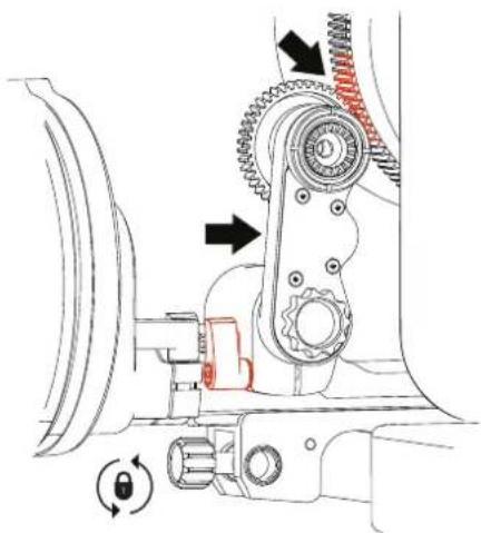

10
Turn the handwheel. Ensure that the drive gear engages and drives the lens focus drive.
marking discs & witness mark
Set the focal distances for the Cine Follow Focus One. Using a suitable pen mark the lens focal reference points on the marking disc. The handwheel is supplied ready with a marking disc.
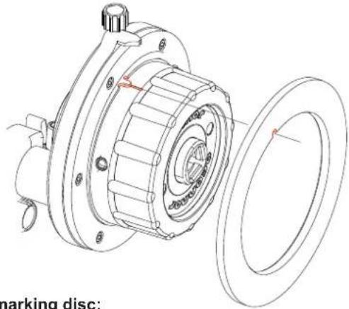
To remove the marking disc:
Pull the marking disc off the handwheel.
To replace the marking disc:
a Ensure that the cutout on the marking disc is aligned with the point on the handwheel.
b Slide the marking disc over the handwheel and push into position, until it clicks.
To move the witness mark:

a Loosen the index on top of the witness mark.

b Rotate the witness mark to the focus point on the marking disc. Secure into position by tightening the index.
CAUTION: Always remove the marking disc before cleaning. Do not use solvents on the CFF-1. Follow the instructions supplied with the marking pen when cleaning the marking discs.
Dismounting
1
Loosen the lock lever on the swing arm to disengage the drive gear from the lens focus drive. Position the drive gear away from the lens and secure using the lock lever.

2
Loosen the knurled screws at the end of the studio rod bridge to release the rod clamps.
3
Lift the Cine Follow Focus One off the camera rods.
Note: If the swing arm is mounted on the front of the main bridge, turn the lock lever counterclockwise to loosen the swing arm.
Storage
1
Remove the drive gear from the swing arm.

2
Loosen the lock lever securing the swing arm and fold the swing arm down onto the main bridge.
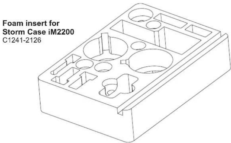
4
Carefully place the components into the foam insert provided.
3
Remove the handwheel(s) by loosening the lock lever at the back of the handwheel and sliding the handwheel free from the main bridge.

To prevent damage, always store the Cine Follow Focus One in a solid case when not in use.
OConnor Offices worldwide
ASIA
CHINA
Room 706, Tower B
Derun Building
YongAn Dongli A No. 8
Jianwai Ave.
Chaoyang District
100022 Beijing, China
Tel.: +86 10 8528 8748
Fax: +86 10 8528 8749
JAPAN
P.A. Building 4F
3-12-6 Aobadai
Meguro-ku
Tokyo 153-0042
Japan
Tel.: +81 3 5457 1381
Fax: +81 3 5457 1382
SINGAPORE
6 New Industrial Road
02-02 Hoe Huat Industrial
Building
Singapore 536199
Tel.: +65 6297 5776
Fax: +65 6297 5778
EUROPE
FRANCE
William Vinten Building
Western Way
Bury St Edmunds
Suffolk IP33 3TB
United Kingdom
Tel.: +44 1284 752 121
Fax: +44 1284 750 560
Sales Fax: +44 1284 757 929

www.ocon.com - sales@ocon.com
HEADQUARTERS
2701 N. Ontario St.
Burbank, CA 91504
USA
Valley Cottage, NY 10989
USA
Tel.: +1 845 268 0100
- COPYRIGHT © 2011 THE VITEC GROUP PLC
- CONTENTS
- ASSEMBLY
- THE CINE FOLLOW FOCUS ONE
- SPECIFICATION
- CINE FOLLOW FOCUS ONE (C1241-0001)
- GEAR ATTACHMENT
- LENSES
- ROD SYSTEM COMPATIBILITY
- IN THE BOX
- ACCESSORIES
- DRIVE GEARS
- MATCHING OCONNOR ACCESSORIES
- STUDIO ROD BRIDGE
- HANDWHEEL (FOR DOUBLE-SIDED USE)
- HANDWHEEL EXTENSION (70 MM)
- GLOW-IN-THE-DARK" MARKING DISC
- CAUTION
- COMPONENTS
- REPOSITIONING THE LOCK LEVERS
- MOUNTING THE SWING ARM & DRIVE GEAR
- MOUNTING THE HANDWHEEL
- MOUNTING ONTO CAMERA RODS
- 7
- ENGAGING THE DRIVE GEAR
- 8
- 9
- 10
- MARKING DISCS & WITNESS MARK
- DISMOUNTING
- 1
- 2
- 3
- STORAGE
- 4
- OCONNOR OFFICES WORLDWIDE
- ASIA
- CHINA
- JAPAN
- SINGAPORE
- HOE HUAT INDUSTRIAL
- EUROPE
- FRANCE
- HEADQUARTERS
Brand : OConnor
Model : Cine Follow Focus One
Category : Camera accessory