
FDM275-O - Switch BOSCH - Free user manual and instructions
Find the device manual for free FDM275-O BOSCH in PDF.


| Product Type | Light Switch |
| Brand | Bosch |
| Model | FDM275-O |
| Dimensions (H x W x D) | 80 mm x 80 mm x 30 mm |
| Weight | 60 g |
| Material | High-grade plastic (polycarbonate) |
| Color | White |
| Rated Voltage | 230 V AC |
| Rated Current | 10 A |
| Frequency | 50/60 Hz |
| Mounting Type | Flush mount (in-wall) |
| Terminal Type | Screw terminals |
| Functions | On/Off control, indicator light (optional) |
| Protection Rating | IP20 (indoor use only) |
| Certifications | CE, RoHS |
| Operating Temperature | -20°C to +40°C |
| Maintenance | Wipe with a dry, soft cloth |
| Spare Parts Availability | Not available separately; replace entire unit |
| Repairability | Non-repairable; replace if faulty |
| Environmental Compliance | RoHS compliant |
Frequently Asked Questions - FDM275-O BOSCH
User questions about FDM275-O BOSCH
0 question about this device. Answer the ones you know or ask your own.
Ask a new question about this device
Download the instructions for your Switch in PDF format for free! Find your manual FDM275-O - BOSCH and take your electronic device back in hand. On this page are published all the documents necessary for the use of your device. FDM275-O by BOSCH.
USER MANUAL FDM275-O BOSCH
natural_image
Line drawing of a rectangular electronic device with a house icon and three directional arrows indicating flow or movement (no text or symbols)FDM275-O
Radio manual call point
Technical Manual
Legal notice
Technical specifications and availability subject to change without notice.
Transmittal, reproduction, dissemination and/or editing of this document as well as utilization of its contents and communication thereof to others without express authorization are prohibited. Offenders will be held liable for payment of damages. All rights created by patent grant or registration of a utility model or design patent are reserved.
Issued by:
Siemens Switzerland Ltd.
Building Technologies Division
International Headquarters
Gubelstrasse 22
CH-6301 Zug
Tel. +41 41 724-2424
www.siemens.com/buildingtechnologies
Edition: 2016-11-28
Document ID: A6V10425652_en--_f
© Siemens Switzerland Ltd, 2014
Table of contents
1 About this document....5
1.1 Applicable documents 7
1.2 Download center 8
1.3 Technical terms and abbreviations .... 8
1.4 Revision history 9
2 Safety 10
2.1 Safety instructions ....10
2.2 Safety regulations for the method of operation....12
2.3 Standards and directives complied with....14
2.4 Release Notes....14
3 Structure and function.... 15
3.1 Overview 15
3.1.1 Details for ordering....16
3.1.2 Scope of delivery 16
3.1.3 Product version ES....16
3.1.4 Power supply 17
3.2 Setup....18
3.3 Function 19
3.3.1 Danger levels....19
3.3.2 Internal alarm indicator....19
3.3.3 Test mode....21
3.3.4 Alarm activation....21
3.3.5 Diagnosis levels....21
3.3.6 Interface to service devices....21
3.4 Accessories....22
3.4.1 Battery pack BAT3.6-10 22
4.1 Fields of application 24
4.2 Mounting site 24
4.3 Environmental influences 24
5 Mounting and installation ....25
5.1 Mounting radio manual call point FDM275-O.... 25
5.2 Installation 26
5.3 Replacing the plastic insert with a glass insert....29
5.4 Installing the protective cover 30
6 Commissioning....31
6.1 Performance check 31
6.2 Localization and device testing 32
7 Maintenance / Repair ....33
7.1 State of operational readiness after alarm activation ....33
7.2 Establishing factory settings....35
7.3 Basic principles for replacing the battery pack....37
7.4 Replacing the battery pack in the radio manual call point 38
8 Specifications ....40
8.1 Technical data....40
8.2 Dimensions 42
8.3 Master gauge for recesses....42
8.4 Environmental compatibility and disposal....43
Glossary 44
Index 45
About this document
Applicable documents
1 About this document
Goal and purpose
This document contains information on the radio manual call point FDM275-O. Following the instructions consistently will ensure that the product can be used safely and without any problems.
Intended use
The radio manual call point FDM275-O may only be used in a fire detection system with a radio gateway approved by the manufacturer. The radio manual call point FDM275-O is compatible with the radio module FDRF272-O.
Target groups
The information in this document is intended for the following target groups:
| Target group | Activity | Qualification |
| Product Manager | Is responsible for information passing between the manufacturer and regional company.Coordinates the flow of information between the individual groups of people involved in a project. | Has obtained suitable specialist training for the function and for the products.Has attended the training courses for Product Managers. |
| Project Manager | Coordinates the deployment of all persons and resources involved in the project according to schedule.Provides the information required to run the project. | Has obtained suitable specialist training for the function and for the products.Has attended the training courses for Project Managers. |
| Project engineer | Sets parameters for product depending on specific national and/or customer requirements.Checks operability and approves the product for commissioning at the place of installation. | Has obtained suitable specialist training for the function and for the products.Has attended the training courses for Product Engineer. |
Document identification
The document ID is structured as follows:
A6Vxxxxxxxx_aaAA_vv
A6Vxxxxxxxxx__--AA_vv
A6Vxxxxxxxxx_aa--_vv
A6Vxxxxxxxxx_----_vv
| ID code1 | Description |
| A6Vxxxxxxx | STEP-ID generated by the STEP system |
| _Separator | |
| aa Language abbreviation in accordance with ISO 639-1 | |
| AA Country abbreviation in accordance with ISO-3166-1 | |
| -- Multilingual or international | |
| vv | Document version, single or double digit: a, b, ...z; aa, ab, ...az; ba, bb, ...bz; etc. |
1 Some documents have different ID codes that are generated by an earlier system. There are also documents with up-to-date ID codes along with additional features in the designation.
| ID code Examples | |
| ID_languageCOUNTRY_version-- = multilingual or international | A6V10215123_deDE_aA6V10215123_en--_aA6V10315123-----_a |
Date format
The date format in the document corresponds to the recommendation of international standard ISO 8601 (format YYYY-MM-DD).
About this document
Applicable documents
Conventions for text marking
Markups
Special markups are shown in this document as follows:
| ▷ | Requirement for a behavior instruction |
| 1.2. | Behavior instruction with at least two operation sequences |
| - | Version, option, or detailed information for a behavior instruction |
| <> | Intermediate result of a behavior instruction |
| <> | End result of a behavior instruction |
| • | Numbered lists and behavior instructions with an operation sequence |
| [→ X] | Reference to a page number |
| 'Text' | Quotation, reproduced identically |
| Identification of keys | |
| > | Relation sign and for identification between steps in a sequence,e.g., 'Menu bar' > 'Help' > 'Help topics' |
| † Text | Identification of a glossary entry |
Supplementary information and tips
i
The 7 symbol identifies supplementary information and tips for an easier way of working.
1.1 Applicable documents
| Document ID | Title |
1.2 Download center
You can download various types of documents, such as data sheets, installation instructions, and license texts via the following Internet address:
http://siemens.com/bt/download
- Enter the document ID in the 'Find by keyword' input box.

You will also find information about search variants and links to mobile applications (apps) for various systems on the home page.
1.3 Technical terms and abbreviations
| Term Explanation | |
| AI Alarm indicator | |
| Battery empty Fault message in the event of a battery failing completely | |
| Battery low Fault message in the event that the spare battery is activated | |
| IAI Internal alarm indicator | |
| LED Light-emitting diode | |
1.4 Revision history
The reference document's version applies to all languages into which the reference document is translated.
i
The first edition of a language version or a country variant may, for example, be version 'd' instead of 'a' if the reference document is already this version.
The table below shows this document's revision history:
| Modification Index | Edition date | Brief description |
| f | 2016-11-28 | • Frequencies specified in 'Technical data' chapter |
| e | 2016-09-30 | • Editorial changes |
| d | 2016-06-27 | • Changes/additions in the following chapters:– 'Replacing the plastic insert with a glass insert |
| c | 2015-10-15 | • Changes/additions in the following chapters:– Installation– Replacing the battery pack in the radio manual call point– Technical data |
| b | 2015-04-01 | • Flashing behavior table added• Editorial changes |
| a | 2014-05-01 | First edition |
i
The language versions and country variants produced by a local company have the same modification index as the corresponding reference document. They are not however included in the table below.
The table below shows the published language versions and country variants with the corresponding modification index:
2 Safety
2.1 Safety instructions
The safety notices must be observed in order to protect people and property.
The safety notices in this document contain the following elements:
• Symbol for danger
- Signal word
• Nature and origin of the danger
• Consequences if the danger occurs
• Measures or prohibitions for danger avoidance
Symbol for danger

This is the symbol for danger. It warns of risks of injury.
Follow all measures identified by this symbol to avoid injury or death.
Additional danger symbols
These symbols indicate general dangers, the type of danger or possible consequences, measures and prohibitions, examples of which are shown in the following table:

General danger

Voltage/electric shock

Battery

Explosive atmosphere

Laser light

Heat
Signal word
The signal word classifies the dancer as defined in the following table:
Safety
Safety instructions
2
How risk of injury is presented
Information about the risk of injury is shown as follows:

WARNING
Nature and origin of the danger
Consequences if the danger occurs
• Measures / prohibitions for danger avoidance
How possible damage to property is presented
Information about possible damage to property is shown as follows:
!
NOTICE
Nature and origin of the danger
Consequences if the danger occurs
• Measures / prohibitions for danger avoidance
2.2 Safety regulations for the method of operation
National standards, regulations and legislation
Siemens products are developed and produced in compliance with the relevant European and international safety standards. Should additional national or local safety standards or legislation concerning the planning, mounting, installation, operation or disposal of the product apply at the place of operation, then these must also be taken into account together with the safety regulations in the product documentation.
Electrical Installations

WARNING
Electrical voltage
Electric shock
- Work on electrical installations may only be carried out by qualified electricians or by instructed persons working under the guidance and supervision of a qualified electrician, in accordance with the electrotechnical regulations.
- Wherever possible disconnect products from the power supply when carrying out commissioning, maintenance or repair work on them.
- Lock volt-free areas to prevent them being switched back on again by mistake.
- Label the connection terminals with external voltage using a 'DANGER External voltage' sign.
- Route mains connections to products separately and fuse them with their own, clearly marked fuse.
- Fit an easily accessible disconnecting device in accordance with IEC 60950-1 outside the installation.
• Produce earthing as stated in local safety regulations.
Mounting, installation, commissioning and maintenance
- If you require tools such as a ladder, these must be safe and must be intended for the work in hand.
- When starting the fire control panel ensure that unstable conditions cannot arise.
- Ensure that all points listed in the 'Testing the product operability' section below are observed.
- You may only set controls to normal function when the product operability has been completely tested and the system has been handed over to the customer.
Testing the product operability
- Prevent the remote transmission from triggering erroneously.
- If testing building installations or activating devices from third-party companies, you must collaborate with the people appointed.
- The activation of fire control installations for test purposes must not cause injury to anyone or damage to the building installations. The following instructions must be observed:
- Use the correct potential for activation; this is generally the potential of the building installation.
- Only check controls up to the interface (relay with blocking option).
- Make sure that only the controls to be tested are activated.
- Inform people before testing the alarm devices and allow for possible panic responses.
• Inform people about any noise or mist which may be produced. - Before testing the remote transmission, inform the corresponding alarm and fault signal receiving stations.
Modifications to the system design and the products
Modifications to the system and to individual products may lead to faults, malfunctioning and safety risks. Written confirmation must be obtained from Siemens and the corresponding safety bodies for modifications or additions.
Modules and spare parts
2.3 Standards and directives complied with
A list of the standards and directives complied with is available from your Siemens contact.
2.4 Release Notes
Limitations to the configuration or use of devices in a fire detection installation with a particular firmware version are possible.

WARNING
Limited or non-existent fire detection
Personal injury and damage to property in the event of a fire.
- Read the 'Release Notes' before you plan and/or configure a fire detection installation.
- Read the 'Release Notes' before you carry out a firmware update to a fire detection installation.

NOTICE
Incorrect planning and/or configuration
Important standards and specifications are not satisfied.
Fire detection installation is not accepted for commissioning.
Additional expense resulting from necessary new planning and/or configuration.
- Read the 'Release Notes' before you plan and/or configure a fire detection installation.
- Read the 'Release Notes' before you carry out a firmware update to a fire detection installation.
3 Structure and function
3.1 Overview
The manual call point FDM275-O is intended for use in areas of a building where a fire can be detected by people who can manually trigger an alarm.
The manual call point FDM275-O consists of a back box, a switching unit, and a battery pack. The manual call point FDM275-O has the following features:
• Manual call points with direct activation
Alarm activation by pressing the pressure point
• Radio communication with:
- Radio gateway
- Other radio devices
• Individual detector addressing
• Alarm indicator with status display (green and red):
- Identifies alarm
- Confirms contact with the radio network
- Confirms detector test
- Battery operation
- Versions with resettable plastic or glass insert
- Surface mounting
• Key for resetting the alarm after alarm activation and for opening the housing

natural_image
Line drawing of a rectangular box with a leaf symbol and directional arrows below (no text or labels)3.1.1 Details for ordering
| Type | Order no. | Designation |
| FDM275-O | S54323-F310-A1 | Radio manual call point with plastic insert 'Neutral' FDMP295 |
| BAT3.6-10 | S54370-Z11-A1 | Battery pack |
| Accessories: | ||
| FDMC295 | A5Q00013440 | Protective cover |
| FDMG295 | A5Q00013442 | Glass insert 'Neutral' |
| FDMP295 | A5Q00013445 | Plastic insert 'Neutral' |
| FDMK295 | A5Q00013448 | Key |
3.1.2 Scope of delivery
The radio manual call point FDM275-O is supplied with a mounted plastic insert 'Neutral' FDMG295 and key FDMK295, and without a battery pack.
The following items must be ordered separately:
• Battery pack BAT3.6-10
- Glass insert Neutral
3.1.3 Product version ES
The product version ES provides the technical status of a device in terms of software and hardware. The product version is provided as a two-digit number. You will find the details of your device's product version:
- On the packaging label
• On the product label or the type plate
Product version on the packaging label
Product version on the product label and the type plate
Details of the product version can be found after the device order number:
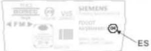
Figure 2: Example of a product label with details of the product version
i
Depending on the product and various approvals, the product labels may differ in terms of the information type and layout.
Look for your device's order number on the product label.
You will find the product version after the order number.
3.1.4 Power supply
The battery pack BAT3.6-10 supplies the radio devices with power. The battery pack consists of lithium batteries plus a battery cable and a battery connector.

3.2 Setup

Figure 4: Radio manual call point FDM275-O
1 Back box 8 Plastic/glass insert
2 Screws for wall mounting ^1
9 Pressure point marking
3 Battery connector 10 Housing cover
4 Battery pack BAT3.6-10 1
11 Key
5 Switching unit 12 Connection for battery connector
6 Internal alarm indicator 13 Housing switching contact
7 Screws for switching unit 14 'new' opening with button
1 Not included in the scope of delivery
3.3 Function
3.3.1 Danger levels
The radio manual call point can transmit the following danger levels to the control panel:
| Danger level Meaning | |
| 0 Normal state, no danger | |
| 3 Alarm |
The evaluation of the danger level and the resulting measures (e.g. activation of remote transmission) are configured on the control panel.
3.3.2 Internal alarm indicator
The internal alarm indicator's LED has two colors and shows the operating condition of the radio manual call point FDM275-O.
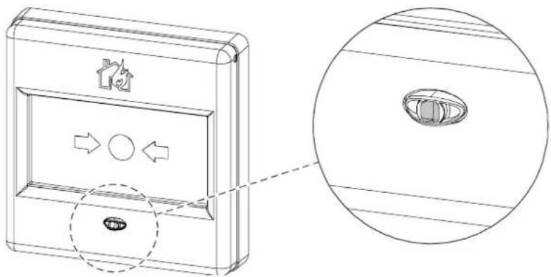
Figure 5: Internal alarm indicator
The table below describes the flashing behavior of the internal alarm indicator in the radio manual call point FDM275-O:
i
Several flashing patterns are available for normal operation. The flashing pattern is selected using the panel configuration program.
| Operating condition Flashing | mode | Graphic | |
| Alarm | IAI flashes red once a second | 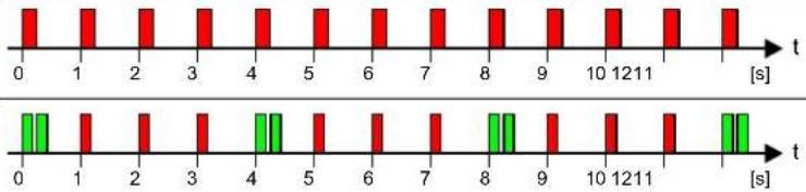 | |
| Alarm in test mode | IAI flashes green twice every four seconds and red every second in-between | ||
| Fault There is an error. | IAI flashes red four times every second |  | |
| Commissioning | The radio manual call point has not yet been logged on to a radio gatewayAndThe radio manual call point is not mounted in the back box.AndThere is no contact with the radio network. | IAI flashes red once every two seconds |  |
| The radio manual call point has already been logged on to a radio gatewayAndThe radio manual call point is not mounted in the back box.AndThere is no contact with the radio network. | IAI flashes green once every two seconds |  | |
| The radio manual call point is mounted in the back box but has not been logged on to the radio network. | IAI flashes green twice every two seconds |  | |
| Normal Configuration 1 | IAI flashes green once every 30 seconds |  | |
| Test | IAI flashes green twice every four seconds |  | |
| Operating condition | Flashing mode | Graphic |
| New battery | IAI lights up once for five seconds |  |
| Battery is flat | IAI off |  |

Several operating conditions may be indicated at the same time. This may lead to the flashing patterns overlapping one another. The red LED indicator has priority over the green LED indicator.
Flashing patterns with a higher frequency will overlap those with a lower frequency, which means that the latter may no longer be discernible.

Not all fire control panels support the flashing patterns described.
Please also observe the documentation for your fire detection system.
3.3.3 Test mode
A test mode can be set on the control panel to test the radio manual call points. When in test mode, alarms from the radio manual call points are not forwarded by the control panel.
3.3.4 Alarm activation
- Press the pressure point on the glass or plastic insert.
The plastic insert falls down or
The glass insert breaks.
The alarm is activated
3.4 Accessories
3.4.1 Battery pack BAT3.6-10
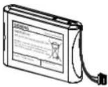
- For supplying radio devices and the radio gateway with power
• Lithium batteries - BAT3.6-10 LI-SOCI2 battery pack 3.6 V, 10 Ah
• Batteries with battery cable - Connector system with protection against polarity reversal
• Inscription field for commissioning date - Compatible with:
- Radio manual call point FDM273-O
- Radio manual call point FDM275-O
- Radio fire detector FDOOT271-0
• Order number: S54370-Z11-A1
3.4.2 Key FDMK295

• For testing and resetting manual call points
- For removing the housing cover from the back box
- Compatible with:
- Radio manual call point FDM275-O
• Order number: A5Q00013448
3.4.4 Plastic insert FDMP295

- For alarm activation and protection against soiling
- Compatible with:
- Radio manual call point FDM275-O
• Order number: A5Q00013445
3.4.5 Protective cover FDMC295
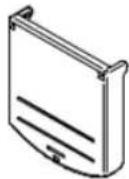
- For protection against unintended alarm activation
- Compatible with:
- Radio manual call point FDM275-O
• Order number: A5Q00013440
4 Planning
4.1 Fields of application
The radio manual call points are intended for use in places where a fire can be detected by people who can manually trigger an alarm.
4.2 Mounting site
The radio manual call points must be mounted in easily accessible places at a height of 0.9...1.6 m on an even surface.
i
Observe the country-specific regulations for the exact mounting height!
4.3 Environmental influences
If the devices are used in industrial applications, consultation with the project manager is required, since plastics do not withstand certain environmental conditions.
The following factors must be taken into consideration:
- Chemicals
- Temperature
- Moisture
5 Mounting and installation
5.1 Mounting radio manual call point FDM275-O
i
Secure the radio manual call point FDM275-O at a height of 0.9...1.6 m on an even surface. Observe the country-specific regulations for the exact mounting height!

Figure 6: Opening the housing with the key FDMK295
The position of radio manual call point FDM275-O has been established.
▷ You have a tool and two screws (max. ∅ 4 mm) for securing purposes.
- Remove the housing cover with the key.
5.2 Installation

1 Back box 9 Screws for switching unit
2 Battery pack BAT3.6-10 ^1
10 Internal alarm indicator
3 Type plate with adhesive label 11 Plastic/glass insert
4 Battery holders 12 Housing cover
5 Battery connector 13 Retainer
6 Housing switching contact 14 Spring
7 Switching unit 15 Triggering device
8 Stop
^1 not included in the scope of delivery

The flashing behavior of the internal alarm indicator is described in document A6V10425652 in the 'Internal alarm indicator' chapter.
The back box is fastened.
▷ You have a new, undamaged battery pack to hand.
▷ You have key FDMK295 and a Phillips screwdriver to hand.
The radio gateway has been activated and switched to maintenance mode.
- Remove the adhesive label with the serial number from the type plate (3) on the switching unit. Use the adhesive label to mark the position of the radio manual call point FDM275-O on the device location plan.
- Label the battery pack (2) with the current date.
-
If the switching unit (7) needs to be switched to 'factory setting'
-
Close the battery connector (5) and press the button in the 'new' opening with a slim pen or pencil for approx. five seconds.
The internal alarm indicator flashes red.
The radio manual call point FDM275-O is set to the factory setting. -
Insert the battery pack into the switching unit so that it snaps into place in the three battery holders (4).
-
Lay the connection cable according to the diagram and connect the battery connector (5).
The internal alarm indicator (10) lights up red.
After a further 10 seconds, the radio manual call point FDM275-O signals that it is not installed in the housing, and the internal alarm indicator flashes every two seconds:
- If it flashes red, this indicates the factory setting.
- If it flashes green, this indicates that the radio manual call point FDM275-O has already been logged on to a radio gateway.
- If this does not happen, this means the battery pack is defective and must not be used.
-
Place the switching unit with the battery pack into the back box (1).
-
Remove the plastic/glass insert (11). Details on replacing the glass can also be found in the "Replacing the plastic insert with a glass insert" chapter.
- Screw the switching unit tightly to the back box (1) using the two screws supplied with the switching unit (9).
- Place the glass/plastic insert (11) between the stops (8) and slide the plastic/glass insert against the triggering device (15), as shown in the diagram.
This pre-stresses the spring (14).
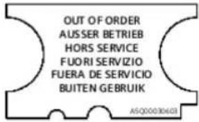
Figure 7: Not in use/ label
See also
Internal alarm indicator [→ 19]
5.3 Replacing the plastic insert with a glass insert
Proceed as follows to replace the plastic insert with a glass insert:
The gateway detector line to which the radio manual call point FDM275-O is logged on is switched off.
-
Remove the housing cover with the key.
-
Remove the plastic insert (1) and dispose of it properly.
-
Place the glass insert (6) between the following points:
-
Retainer (5)
- Left and right stops (4)
- Spring (2)
-
Triggering device (3)
→ This pre-stresses the spring (2). -
Install the housing cover on the back box.
-
Hook the top housing cover into the back box.
- Snap the bottom housing cover into place in the back box.
→ The plastic insert is replaced with a glass insert.
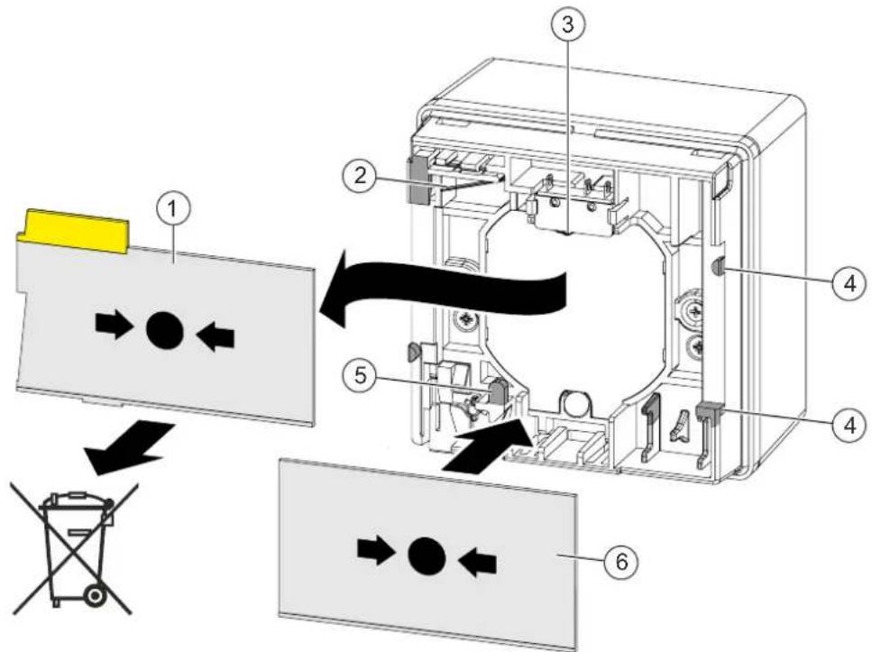
Figure 8: Replacing the plastic insert with a glass insert
1 Plastic insert 4 Stop
2 Spring 5 Retainer
3 Triggering device 6 Glass insert
5.4 Installing the protective cover
If a protective cover (accessories) is being used, proceed as described below:
The radio manual call point has been installed and electrically connected. See the chapter 'Installation [→ 26]'.
A compatible protective cover is available. See the chapter 'Protective cover FDMC295'.
- Snap the protective cover FDMC295 (2) into place in the recesses in the housing cover (1) intended for this purpose. See also 'Protective cover FDMC295' chapter.
The protective cover is installed.

Figure 9: Installing the protective cover FDMC296
1 Radio manual call point FDM275-0
2 Protective cover
6 Commissioning
When the battery connector is connected, the radio manual call point FDM275-O is activated.
i
Insert the battery packs into the devices at the location where they are going to be used just before commissioning the fire detection installation.
Once the switching unit is inserted into the housing, the radio manual call point FDM275-O automatically looks for radio devices within range in the vicinity and automatically integrates itself into the radio network.
The device is commissioned via the control panel. The exact procedure is described in the control panel documentation.
Conduct a performance check once commissioning is complete.
See also the following documents for more information:
• Document A6V10425603
6.1 Performance check
The radio manual call point FDM275-O is installed and electrically connected.
- Set the detector line to "Test" on the control panel.
The internal alarm indicator flashes green with flashing pattern number 8.
- Insert the key into the housing from below, as shown in the diagram.
The glass insert or plastic insert falls down and activates the alarm actuator in the switching unit.
The alarm signal is transmitted.
The internal alarm indicator flashes green and red with flashing pattern number 6 and number 8.
- Pull off the key.
The glass insert or plastic insert is pushed back into its original position.
The manual call point is ready for operation again.
6.2 Localization and device testing
The manual call points have an internal alarm indicator [→ 19]. This internal alarm indicator may also be activated from the control panel for localization and device testing. The table shows the LED indication for the different control panel commands.
| Command | LED Indication |
| Device test | Flashes green |
| Localization | Flashes red |
See also
Internal alarm indicator [→ 19]
7 Maintenance / Repair
7.1 State of operational readiness after alarm activation
Radio manual call point FDM275-O with plastic insert
The plastic insert has fallen down, the yellow marking is visible, and the internal alarm indicator flashes red.
1. Slide the key into the housing.
2. Pull the key out of the housing and push the plastic insert upward.
→ The internal alarm indicator stops flashing.
→ The radio manual call point FDM275-O is ready for operation.

flowchart
graph TD
    A["①"] --> B["Device 1"]
    B --> C["Device 2"]
    C --> D["Device 3"]
    D --> E["Device 4"]
Figure 11: Establishing the state of operational readiness of the radio manual call point with plastic insert
Radio manual call point FDM275-O with glass insert
The glass insert is covered by a foil. This foil holds the glass splinters together when the glass insert is pushed in, making it possible to remove the glass insert easily.
The glass insert is broken and the internal alarm indicator flashes red with flashing pattern number 6.
- Remove the housing cover with the key.
→ The switching unit is accessible.
-
Completely remove the broken glass insert (1) and dispose of it properly.
-
Place the new glass insert (6) between the following points:
- Retainer (5)
- Left and right stops (4)
- Spring (2)
-Triggering device (3)
→ This pre-stresses the spring (2).
- Install the housing cover on the back box.
- Hook the top housing cover into the back box.
- Snap the bottom housing cover into place in the back box.
- If necessary, check the function of the manual call point. See the chapter 'Performance check'.
→ The radio manual call point FDM275-O is ready for operation.

Figure 12: Replacing the glass insert
1 Broken glass insert 4 Stop
2 Spring 5 Retainer
3 Triggering device 6 New glass insert
7.2 Establishing factory settings
All existing settings are deleted and reset to the factory settings. The radio manual call point FDM275-O can only be integrated into a radio cell as a new device if it is set to its factory settings.

Figure 13: Establishing factory settings
1 Switching unit (rear view)
2 Battery pack BAT3.6-10
3 'new' opening with button
4 Pen or pencil
The battery pack is connected.
1. Remove the housing cover with the key.
2. Remove the plastic/glass insert
If the detector line is not switched off, the internal alarm indicator (6) flashes red (flashing pattern number 6 with an interval of 1 second [→ 19]).
3. Unscrew the two screws and remove the switching unit (1) from the back box
The internal alarm indicator flashes green (flashing pattern number 3 with an interval of: 2 seconds [→ 19]).
4. Remove the connected battery pack (2) from the holder.
5. Press the button in the 'new' opening (3) with a slim pen or pencil (4) for approx. five seconds.
The internal alarm indicator flashes red every 2 seconds.
The radio manual call point FDM275-O is set to the factory setting (Installation [→ 26]).
7.3 Basic principles for replacing the battery pack

WARNING
Risk of explosion due to fire or short-circuit, even if the battery pack is discharged Injuries caused by flying parts
- To prevent the connection wires short-circuiting, insulate the connections and stick the battery cable to the battery pack.
- Do not allow the battery pack to come into contact with water.
• Do not extinguish a burning battery pack with water.
• Do not recharge the battery pack.
• Do not damage or dismantle the battery pack.
• Do not heat the battery pack to more than 100 °C.

WARNING
Disposing of damaged or leaky battery packs
Lithium can burn the skin and produce toxic vapors.
- Avoid direct contact with the body. Wear appropriate protective clothing (safety gloves, safety goggles, etc.). Use appropriate means of transportation to move damaged batteries around.
- Do not breathe in vapors. Ensure that there is sufficient ventilation.
Always observe the following information:
- When the control panel issues the message 'Battery low', replace the battery pack.
• Use the control panel to identify the location of the radio device.
• Only use battery pack BAT3.6-10. - The battery pack must be new and free from damage. The battery cable is attached to the battery pack with an additional label.
7.4 Replacing the battery pack in the radio manual call point
| ! | NOTICE |
| Unintentional alarm activationRemoving the glass or plastic insert triggers an alarm if the detector line is activated.Switch off the detector line or switch it to maintenance mode. |
- Do not interrupt the power supply for longer than 2 minutes.
- Do not interrupt the power supply to multiple radio devices simultaneously. Replace the battery pack for one radio device as described below before replacing the battery pack for the next radio device. This will prevent mix-ups and will ensure the devices can be reintegrated into the radio cell without any problems.

-
Remove the housing cover with the key.
-
Remove the plastic/glass insert (1).
If the detector line is not switched off, the internal alarm indicator (6) flashes red (interval of: 1 second).
-
Loosen the two screws (2).
-
Remove the switching unit (2) with the connected battery pack (9).
-
Wait until the internal alarm indicator (6) flashes green (flashing pattern number 3 with interval of 2 seconds).
⇒ The radio manual call point is 'out of base'.
-
Remove the old battery pack (9).
-
Release the battery connector (8).
– Dispose of the old battery pack. -
Label the new battery pack with the current date.
-
Connect the battery connector (8).
→ The alarm indicator lights up red for 5 seconds.
After a further 10 seconds, the radio manual call point FDM275-O signals that it is no longer installed in the housing and the alarm indicator flashes green (flashing pattern number 3 with interval of 2 seconds).
If this does not happen, this means the battery pack is defective and must not be used.
-
Lay the connection cable according to the diagram and snap the battery pack in place in the three battery holders.
-
Insert the switching unit with the new battery pack into the back box and screw it tightly in place.
-
The internal alarm indicator flashes green (flashing pattern number 4) and the radio manual call point FDM275-O is logged on to the radio gateway.
-
Insert the glass or plastic insert.
If the process of logging on to the radio gateway is successful, the internal alarm indicator stops flashing.
- If the logon process has not been successful after a long period of time, remove the switching unit from the back box and then re-insert it.
→ The search for the radio network starts again.
- Install the housing cover on the back box.
– Hook the top housing cover into the back box.
- Snap the bottom housing cover into place in the back box.
→ The battery pack has now been replaced.
8 Specifications
8.1 Technical data
You will find information on approvals, CE marking, and the relevant EU directives for this device (these devices) in the following document(s); see 'Applicable documents' chapter:
- Document A6V10431682
Device characteristics
| Detector diagnosis | With Wireless diagnostic tool or connected fire control panel |
| Type of alarm activation | Type A (direct activation) |
Radio
| Sending/receiving aerials | Dual band aerial |
| Frequency range | 433.05...434.79 MHz in band 44b and 45b^1 868...870 MHz in band 48, 49, 50, 54b, and 56b^1 |
| Channel grid | 50 kHz |
| Number of channels | 27 in 868-MHz band20 in 433-MHz band |
| Transmitting power | ≤10 mW ERP in band 44b, 45b, and 49^1 Type 10 (max. ≤25) mW ERP in band 48, 50, 54b and 56b^1 |
| Range | See document A6V10425603 |
2013/752/EU: according Official Journal of the European Union, COMMISSION IMPLEMENTING DECISION of 11 December 2013 amending Decision 2006/771/EC on harmonisation of the radio spectrum for use by short-range devices and repealing Decision 2005/928/EC (notified under document C(2013) 8776) (Text with EEA relevance)
Specifications
Technical data
8
Ambient conditions
Place of installation Inside buildings/indoors
| Operating temperature | -10...+55 °C |
| Storage temperature | -30...+75 °C |
| Air humidity | ≤95 % rel. |
Protection categories (IEC 60529): IP24D
| Electromagnetic compatibility: | |
| 10 kHz...100 kHz | 160 V/m |
| 100 kHz...2.5 GHz | 30 V/m |
Mechanical data
| Weight: | 0.216 kg |
| Housing material | Red => Polycarbonate (PC)Black => Acrylonitrile butadiene styrene (ABS) |
| Housing color | -RAL 3000 flame red |
Standards
| European standards | EN 54-11 |
| EN 54-25 | |
| EN 300220-2 | |
| EN 301489-3 | |
| EN 60950-1 |
8.2 Dimensions

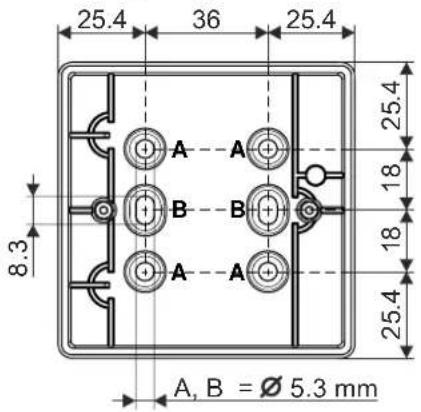
8.3 Master gauge for recesses
8.4 Environmental compatibility and disposal

This equipment is manufactured using materials and procedures which comply with current environmental protection standards as best as possible. More specifically, the following measures have been undertaken:
• Use of reusable materials
• Use of halogen-free plastics
• Electronic parts and synthetic materials can be separated
Larger plastic parts are labeled according to ISO 11469 and ISO 1043.
The plastics can be separated and recycled on this basis.

Electronic parts and batteries must not be disposed of with domestic waste.
• Take electronic parts and batteries to local collection points or recycling centers.
- Contact local authorities for more information.
- Observe national requirements for disposing of electronic parts and batteries.
Glossary
Factory setting
Basic settings present at the time of delivery
Radio device
Any device that the radio gateway monitors
Index
A
Application area
Ambient conditions.... 24
Approvals 40
B
Battery pack
Description.... 22
Replacing 38
Replacing the battery pack 37
C
CE marking 40
Control panel 31
D
Danger levels
Signals transmitted to the control panel ..... 19
Disposal 43
Documentation for fire detection system 21
Download center
URL 8
E
Environmental compatibility 43
Environmental influences.... 24
ES
Product version 16
EU directives 40
F
Flashing mode
Internal alarm indicator 19
Flashing pattern
Configuration 19
Internal alarm indicator 19
|
Impact
Chemicals 24
Moisture 24
Temperature 24
Intended use 5
P
Packaging label
Product version 16
Product label
Product version 16
R
Radio manual call point
Test mode 21
Recycling 43
Resetting after an alarm 21
Restoring to a state of operational readiness ..... 21
S
Signals transmitted to the control panel
Danger levels.... 19
Standards 41
T
Test mode
Radio manual call point 21
Type plate
Product version 16
Issued by
Siemens Switzerland Ltd
Building Technologies Division
International Headquarters
Gubelstrasse 22
CH-6301 Zug
+41 41-724 24 24
www.siemens.com/buildingtechnologies
© Siemens Switzerland Ltd, 2014
Technical specifications and availability subject to change without notice.


- FDM275-O
- Radio manual call point
- Technical Manual
- Legal notice
- Table of contents
- About this document
- About this document
- Goal and purpose
- Intended use
- Target groups
- Document identification
- Date format
- Applicable documents
- Conventions for text marking
- Markups
- Supplementary information and tips
- Applicable documents
- Download center
- Technical terms and abbreviations
- Revision history
- Safety
- Safety instructions
- Symbol for danger
- Additional danger symbols
- Signal word
- How risk of injury is presented
- WARNING
- Nature and origin of the danger
- How possible damage to property is presented
- NOTICE
- Safety regulations for the method of operation
- National standards, regulations and legislation
- Electrical Installations
- Electrical voltage
- Mounting, installation, commissioning and maintenance
- Testing the product operability
- Modifications to the system design and the products
- Modules and spare parts
- Standards and directives complied with
- Release Notes
- Limited or non-existent fire detection
- Incorrect planning and/or configuration
- Structure and function
- Overview
- Details for ordering
- Scope of delivery
- Product version ES
- Product version on the product label and the type plate
- Power supply
- Setup
- Function
- Danger levels
- Internal alarm indicator
- Test mode
- Alarm activation
- Accessories
- Battery pack BAT3.6-10
- Key FDMK295
- Plastic insert FDMP295
- Protective cover FDMC295
- Planning
- Fields of application
- Mounting site
- Environmental influences
- Mounting and installation
- Mounting radio manual call point FDM275-O
- Installation
- See also
- Replacing the plastic insert with a glass insert
- Installing the protective cover
- Commissioning
- Performance check
- Localization and device testing
- Maintenance / Repair
- State of operational readiness after alarm activation
- Radio manual call point FDM275-O with plastic insert
- Radio manual call point FDM275-O with glass insert
- Establishing factory settings
- Basic principles for replacing the battery pack
- Replacing the battery pack in the radio manual call point
- Specifications
- Technical data
- Dimensions
- Master gauge for recesses
- Environmental compatibility and disposal
- Glossary
- Factory setting
- Radio device
- Index
- A
- B
- C
- D
- E
- F
- |
- P
- R
- S
- T
Brand : BOSCH
Model : FDM275-O
Category : Switch