SUN-7K-G03-P - Solar panel Deye - Free user manual and instructions
Find the device manual for free SUN-7K-G03-P Deye in PDF.

User questions about SUN-7K-G03-P Deye
0 question about this device. Answer the ones you know or ask your own.
Ask a new question about this device
Download the instructions for your Solar panel in PDF format for free! Find your manual SUN-7K-G03-P - Deye and take your electronic device back in hand. On this page are published all the documents necessary for the use of your device. SUN-7K-G03-P by Deye.
USER MANUAL SUN-7K-G03-P Deye
Grid-tied PV String Inverter
SUN-15K-G03
SUN-17K-G03
User Manual
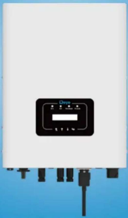
natural_image
Front view of a white industrial control panel with black buttons and connector pins (no readable text or symbols)Contents
- Introduction - 01 -
1.1 Appearance Introduction - 01 -
1.2 Parts list - 02 -
- Safety warnings and instructions - 03 -
2.1 Safety signs - 03 -
2.2 Safety instructions 03 -
2.3 Notes for using 04 -
- Operation Interface 05 -
3.1 Interface View 05 -
3.2 Status Indicator 05 -
3.3 Buttons - 06 -
3.4 LCD Display - 06-
- Product installation 07 -
4.1 Select installation location ...... - 07 -
4.2 Inverter Installation 09 -
- Electrical Connection 11 -
5.1 DC input terminal connection - 11 -
5.2 AC input terminal connection 13 -
5.3 The connection of the ground line 16 -
5.4 Max. over current protection device - 17 -
5.5 Inverter monitoring connection 17 -
5.6 Installation of datalogger - 18 -
5.7 Configuration of Datalogger - 18 -
- Startup and Shutdown - 19 -
6.1 Start up the inverter - 19 -
6.2 Inverter Shutdown - 19 -
- Zero export function via SUN limiter - 20 -
7.1 SUN Limiter function wiring diagram - 20 -
7.2 Connect the SUN limiter to inverter 21 -
7.3 Use of zero export function 23 -
7.4 Zero-export function (Option) - 24 -
7.5 Notes while using zero export function ...... - 29 -
7.6 How to browse the load power of your PV grid-tieplant on monitoring platform? - 29 -
- General Operation - 31 -
8.1 The initial interface - 31-
8.2 Submenus in the Main Menu - 32 -
8.3 System param setting.... - 35 -
8.4 Running param set.... - 35 -
8.5 Protect Param - 37-
8.6 Comm. param set - 39 -
-
Repair and Maintenance 39 -
-
Error information and processing 39 -
10.1 Error code - 40 -
- Specification - 44-
About This Manual
The manual mainly describes the product information, guidelines for installation, operation and maintenance. The manual cannot include complete information about the photovoltaic (PV) system.
How to Use This Manual
Read the manual and other related documents before performing any operation on the inverter. Documents must be stored carefully and be available at all times. Contents may be periodically updated or revised due to product development. The information in this manual is subject to change without notice. The latest manual can be acquired via service@deye.com.cn
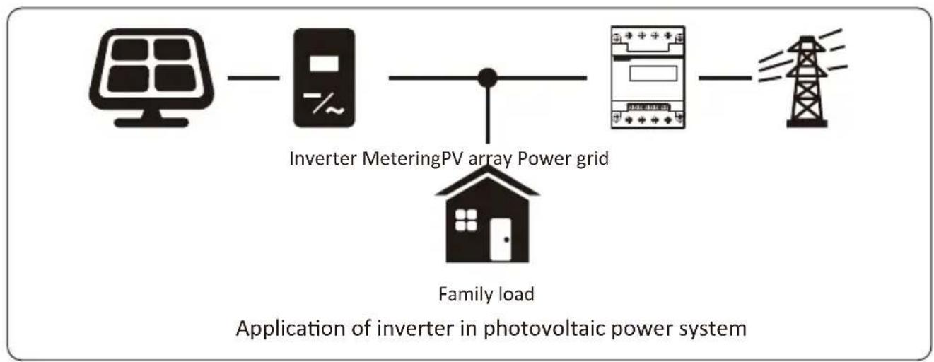
Photovoltaic Grid-connected System
flowchart
graph LR
    A["Solar Panel"] --> B["Inverter Metering PV array Power grid"]
    B --> C["Grid Connection"]
    C --> D["Power Tower"]
    style A fill:#f9f,stroke:#333
    style B fill:#ccf,stroke:#333
    style C fill:#cfc,stroke:#333
    style D fill:#fcc,stroke:#333
1. Introduction
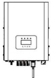
1.1 Appearance Introduction
On-grid inverter can convert solar panel DC power into AC power which can directly input to the grid. Its appearance is shown below. These models contain SUN-15K-G03、SUN-17K-G03. The following is collectively referred to as 'inverter'.
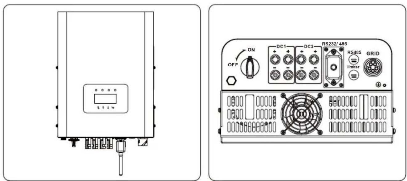
Pic 1.1 Front view Pic 1.2 Bottom view
1.2 Parts list
Please check the following table, to see whether all the parts are included in the package:
natural_image
Simple line drawing of a rectangular device with a control panel and ports (no text or symbols)Grid-tied PV String Inverter x1
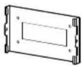
Wall mounting bracket x1
Mounting stainless steel screws M4×12 x4
natural_image
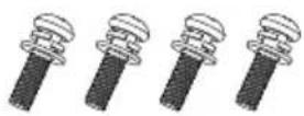
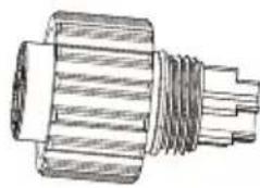
Technical line drawing of a cylindrical mechanical component with flanged ends (no text or symbols)AC power connectors x1
natural_image
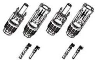
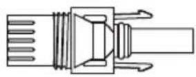
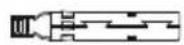
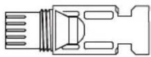
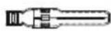
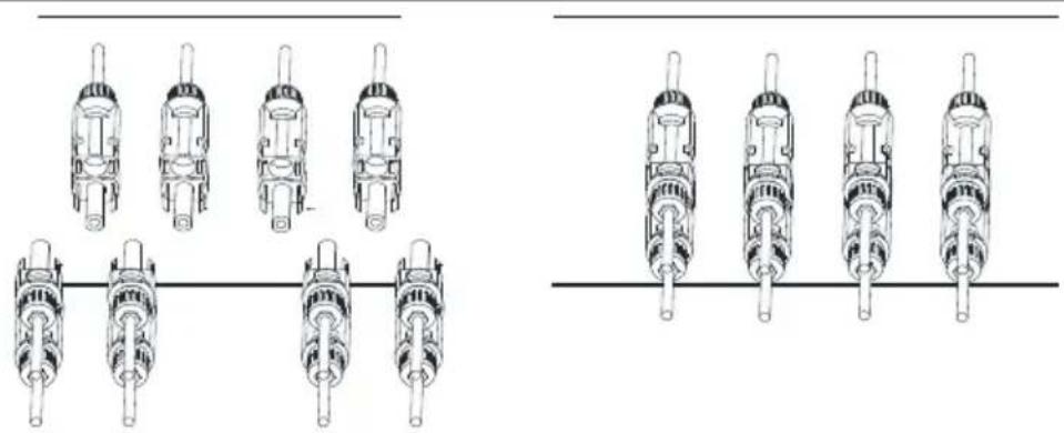
Technical line drawings of four different mechanical components or assemblies (no text or symbols present)DC power connectors (including Inserted spring) x3
natural_image
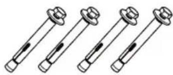
Four identical mechanical bolted components with threaded ends and fasteners, shown in a row (no text or symbols)Stainless steel anti-collision bolt M6×80 x4
User manual x1
natural_image
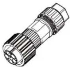
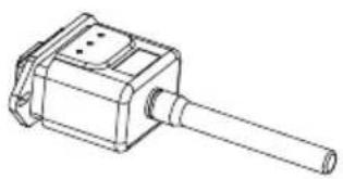
Technical line drawing of a mechanical component with a cylindrical shaft and housing (no text or symbols)Datalogger (optional) x1
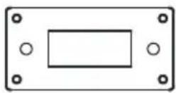
Square hole sealing plate (For WIFI function) x1
natural_image
Simple diagram of a device with a green progress bar and a circular button, no text or symbols present.SUN limiter(optional) x 1
natural_image
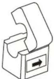
Simple line drawing of a mechanical component with an arrow indicating direction (no text or symbols)*Sensor Clamp x 3
When ordering the sun limiter, it will includes 3pcs CT.
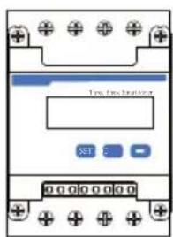
Meter(optional) x 1
2. Safety warnings and instructions
Improper use may result in potential electric shock hazards or burns. This manual contains important instructions that should be followed during installation and maintenance. Please read these instructions carefully before use and keep them for future reference.
2.1 Safety signs
Safety symbols used in this manual, which highlight potential safety risks and important safety information, are listed as follows:
Warning:
Warning symbol indicates important safety instructions, which if not correctly followed, could result in serious injury or death.
Shock Hazard:
Caution, risk of electric shock symbol indicates important safety instructions, which if not correctly followed, could result in electric shock.
Safety Hint:
Note symbol indicates important safety instructions, which if not correctly followed, could result in some damage or the destruction of the inverter.

High Temperature Hazard:
Caution, hot surface symbol indicates safety instructions, which if not correctly followed, could result in burns.
2.2 Safety instructions

Warning:
Electrical installation of the inverter must conform to the safety operation rules of the country or local area.
Warning:
Inverter adopts non-isolated topology structure, hence must insure DC input and AC output are electrical isolated before operating the inverter.
Strictly prohibit grounding the positive and negative poles of the PV string.
Otherwise it will damage the inverter.
Shock Hazard:
Prohibit disassembling inverter case, there existing shock hazard, which may cause serious injury or death, please ask qualified person to repair.
Shock Hazard:
When PV module is exposed to sunlight, the output will generate DC voltage. Prohibit touching to avoid shock hazard.
Shock Hazard:
While disconnect the input and output of the inverter for maintenance, please waits for at least 5 mins until the inverter discharge the remnant electricity.
High Temperature Hazard:
Local temperature of inverter may exceed 80 ℃ while under operating. Please do not touch the inverter case.
2.3 Notes for using
The three phase string power inverter is designed and tested under related safety regulations. It can ensure the personal safety of the user. But as a electric device, it may cause shock or injury by incorrect operation. Please operate the unit under below requirements:
- Inverter should be installed and maintained by qualified person under local standard regulations.
- Must disconnect the AC side first, then disconnect DC side while doing installation and maintenance, after that, please wait at least 5 mins to avoid getting shocked.
- Local temperature of the inverter may exceed 80 °C while under operating. Do not touch to avoid getting injured.
- All electrical installation must be in accord with local electrical standards, and after obtaining the permission of the local power supply department, the professionals can connect the inverter to the grid.
- Please take appropriate anti-static measure.
- Please install where children can not touch.
- When starting the inverters, first close the circuit breaker at the grid side, then close the DC side; when closing the inverters, first disconnect the circuit breaker at the AC side, then disconnect the DC side.
- Don't insert or remove AC and DC terminals when the inverter is in normal operation.
- The DC input voltage of the inverter must not exceed the maximum value of the model.
3. Operation Interface
3.1 Interface View
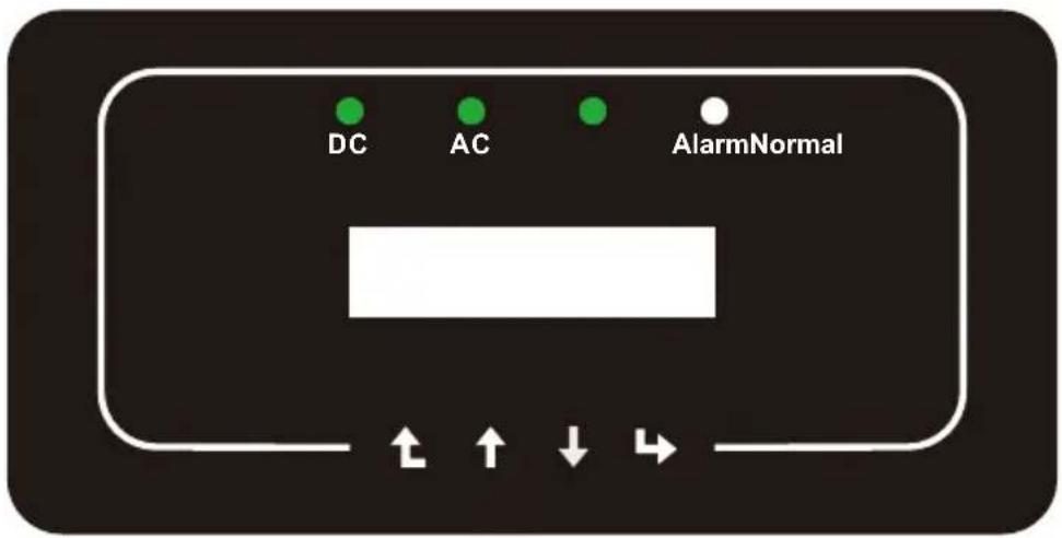
Pic 3.1 Front panel display
3.2 Status Indicator
There are four LED status indicator lights in the front panel of the inverter. Please see table 3.1 for details.
| Indicator status | Explanation | |
| DC | on | Inverter detects DC input |
| off | Low DC input voltage | |
| AC | on | Grid Connected |
| off | Grid Unavailable | |
| NORMAL | on | Under normal operating |
| off | Stop operating | |
| ALARM | on | Detected faults or report faults |
| off | Under normal operating | |
Table 3.1 Status indicator lights
3.3 Buttons
There are four keys in the front panel of the Inverter(from left to right): Esc, Up, Down and Enter keys. The keypad is used for:
- Scrolling through the displayed options (the Up and Down keys);
- Access to modify the adjustable settings (the Esc and Enter keys).

Esc Up Down-Inter


3.4 LCD Display
The two-line Liquid Crystal Display (LCD) is located on the front panel of the Inverter, which shows the following information:
- Inverter operation status and data;
● Service messages for operator; - Alarm messages and fault indications.
4. Product installation
4.1 Select installation location
To select a location for the inverter, the following criteria should be considered:
WARNING: Risk of fire
- Do not install the inverter in areas containing highly flammable materials or gases.
- Do not install the inverter in potentially explosive atmospheres.
- Do not install in small closed spaces where air can not circulate freely. To avoid overheating, always make sure the flow of air around the inverter is not blocked.
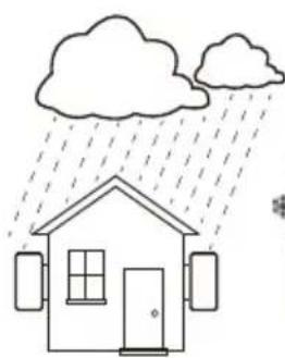
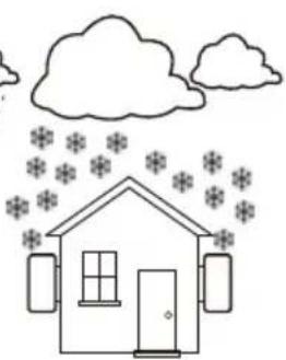
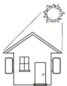
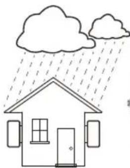
- Exposure to direct sunlight will increase the operational temperature of the inverter and may cause output power limiting. It is recommended that inverter installed to avoid direct sunlight or raining.
- To avoid overheating ambient air temperature must be considered when choosing the inverter installation location. It is recommended that using a sun shade minimizing direct sunlight when the ambient air temperature around the unit exceeds 100^ F / 40^ C .
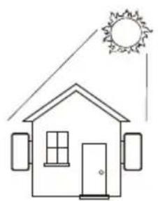
natural_image
Simple line drawing of a house under a sun, no text or symbols present×
natural_image
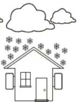
Simple line drawing of a house under rain with cloud and raindrops (no text or symbols)×
natural_image
Simple line drawing of a house with snowflakes above and clouds above (no text or symbols)×
natural_image
Simple line drawing of a house with sun and roof, no text or symbols present√
natural_image
Simple line drawing of a house under rain with cloud and raindrops (no text or symbols)√
natural_image
Simple line drawing of a house with cloud and snowflake patterns above (no text or symbols)√
Pic 4.1 Recommended installation place
- Install on a wall or strong structure capable of bearing the weight.
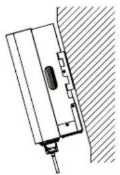
- Install vertically with a maximum incline of +/-15^ . If the mounted inverter is tilted to an angle greater than the maximum noted, heat dissipation can be inhibited, and may result in less than expected output power.
- If install more than one inverter, must leave at least 500mm gap between each inverter. And each inverter must be at least 500mm above and below. And must install the inverter at the place where children cannot touch. Please see picture 4.3.
- Consider whether the installation environment is helpful to see the inverter LCD display and indicator status clearly.
- Must offer a ventilate environment if inverter installed in the airtight house.
Safety Hint:
Do not place or store any items next to the inverter.
natural_image
Technical line drawing of a mechanical component with hatched background (no text or symbols)×
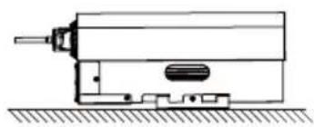
natural_image
Technical line drawing of a mechanical device with no visible text or symbols×
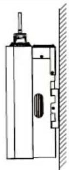
natural_image
Technical line drawing of a mechanical device with a vertical wall and handle (no text or symbols)×
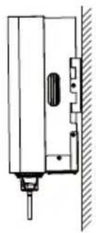
natural_image
Technical line drawing of a door lock assembly with handle and bracket (no text or symbols)√
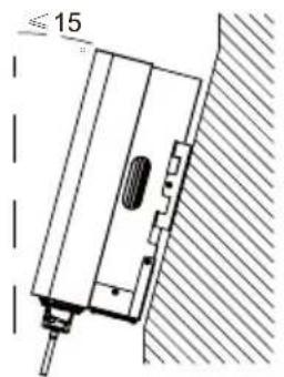
√
Pic 4.2 Installation Angle
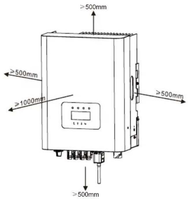
Pic 4.3 Installation Gap
4.2 Inverter Installation
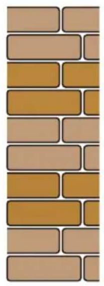
The inverter is designed according to the wall mounted type installation, please use the wall mounted (the brick wall of the expansion bolt) when installing.
natural_image
Vertical pattern of interlocking brown and beige rectangular blocks (no text or symbols)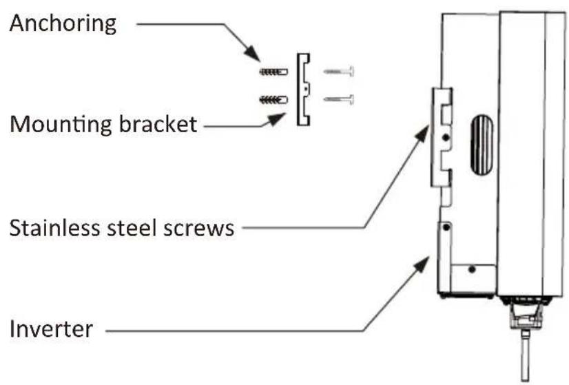
Pic 4.4 Inverter Installation
Procedure shows below:
- Locate on the appropriate wall according to the bolt position on the mounting bracket, then mark the hole. On the brick wall, the installation must be suitable for the expansion bolt installation.
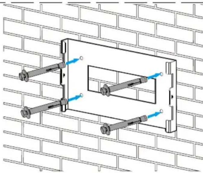
natural_image
Technical diagram of a mechanical assembly mounted on a brick wall, showing bolted components and directional arrows (no text or labels)Pic 4.5 Inverter hanging plate installation
- Ensure that the position of the installation holes on the wall is in accordance with the mounting plate, and the mounting rack is horizontally placed.
- Hang the inverter to the top of the mounting rack and then use the M4 screw in the accessory to lock inverter heat sink to the hanging plate, to ensure that the inverter will not move.
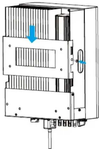
natural_image
Technical diagram of a mechanical device with internal components and directional arrows (no text or symbols)Pic 4.6 Inverter installation
5 Electrical Connection
5.1 DC input terminal connection
- Switch the Grid Supply Main Switch(AC)OFF.
- Switch the DC Isolator OFF.
- Assemble PV input connector to the inverter.
Safety Hint:
Please don't connect PV array positive or negative pole to the ground, it could cause serious damages to the inverter.
Safety Hint:
Before connection, please make sure the polarity of the output voltage of PV array matches the "DC+" and "DC-" symbols.
Safety Hint:
Before connecting inverter, please make sure the PV array open circuit voltage is within the 1000V of the inverter.
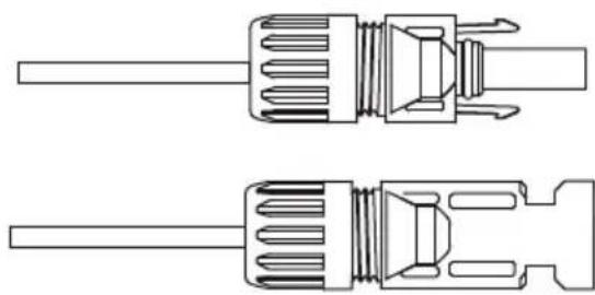
Pic 5.1 DC+connector (MC4)
Pic 5.2 DC-connector (MC4)
Safety Hint:
Please use approved DC cable for PV system.
| Cable type | Cross section (mm2) | |
| Range Recommended value | ||
| Industry generic PV cable (model: PV1-F) | 4.0~6.0(12~10AWG) | 4.0(12AWG) |
Table 5.1 DC Cable Specifications
The steps to assemble the DC connectors are listed as follows:
a) Strip off the DC wire about 7mm, disassemble the connector cap nut (see picture 5.3).
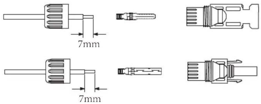
Pic 5.3 Disassemble the connector cap nut
b) Crimping metal terminals with crimping pliers as shown in picture 5.4.
Pic 5.4 Crimp the contact pin to the wire
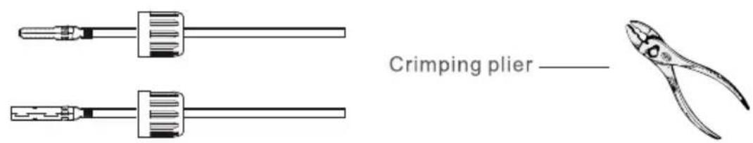
c) Insert the contact pin to the top part of the connector and screw up the cap nut to the top part of the connector. (as shown in picture 5.5).
natural_image
Technical line drawing of two mechanical components with threaded leads (no text or symbols)Pic 5.5 connector with cap nut screwed on
d) Finally insert the DC connector into the positive and negative input of the inverter, shown as picture 5.6
natural_image
Technical line drawings of mechanical components with no visible text or symbolsPic 5.6 DC input connection
Warning:
Sunlight shines on the panel will generate voltage, high voltage in series may cause danger to life. Therefore, before connecting the DC input line, the solar panel needs to be blocked by the opaque material and the DC switch should be 'OFF', otherwise, the high voltage of the inverter may lead to life-threatening conditions.
5.2 AC input terminal connection
Do not close the DC switch after the DC terminal is connected. Connect the AC terminal to the AC side of the inverter, the AC side is equipped with Three phase AC terminals that can be conveniently connected. Flexible cords are recommended for easy installation. The specifications are as shown in Table 5.2.
Warning:
Prohibit using a single circuit breaker for multiple inverters, prohibit the connection of load between inverter circuit breakers.
| Model | Cable CSA | Cable outer dia | AWG | Breaker | Max cable length |
| SUN-15K/17K-G03 | 2 | 20-25mm 30A/40006mm | Outside cable (3+N+PE)20m | ||
Table 5.2 Cable information
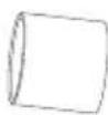
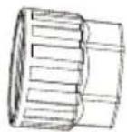
The AC output connector is divided into three parts: matching socket, sleeve and sealing-sleeve, as shown in picture 5.7, the steps are as follows:
Step 1: Remove the cable sealing ring and sleeve in sequence from the AC connector.
Step 2: Use strippers to strip the protective sheath and insulation layer of the AC cable to the right length, as shown in Picture 5.8.
natural_image
Technical line drawing of a threaded mechanical component (no text or symbols)1
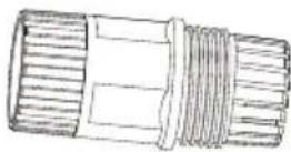
2
3
4
- Matching socket
2.Sleeve
3.Sealing core
4.Sealing nut
Pic 5.7 AC connector structure
Step 3: Insert the cable (L1, L2, L3, N, PE) into the sealing sleeve.
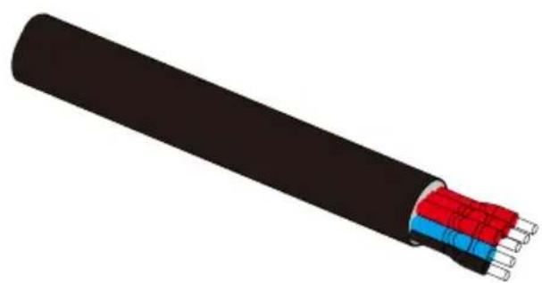
natural_image
3D illustration of a black cable with red and blue insulation layers (no text or symbols)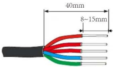
Pic5.8 Strip AC cable
Warning:
Be careful to distinguish the L1, L2, L3, N and PE of the AC cables.
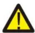
Step 4: Use the hexagon screwdriver, loosen the bolts of the socket in turn, and insert each cable core into the corresponding jack, and set each screw. The connection hole of AC connection terminal labeling is shown in Picture 5.9.
natural_image
Technical line drawing of a mechanical component with four circular ports and labeled terminals (N, P, Z), no readable text or symbols beyond labels.Pic 5.9 AC Connector Hole Pattern
Step 5: Set the sleeve and sealing ring in place.
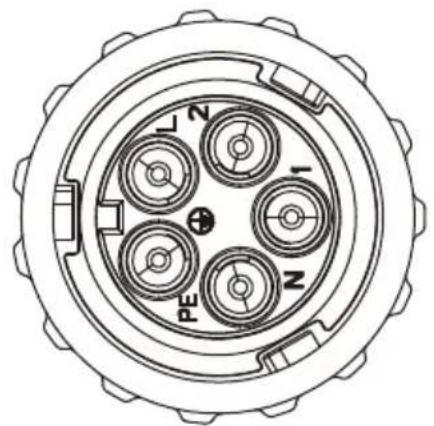
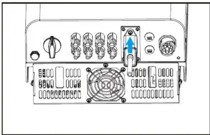
Step 6: Connect the terminals to the inverter as shown in picture 5.10.
natural_image
Technical diagram of an electronic device front panel with ports, connectors, and a highlighted cable (no text or symbols)Pic 5.10 AC input connection
5.3 The connection of the ground line
Good grounding is good for resisting surge voltage shock and improving EMI performance. Therefore, before connecting AC, DC and communication cables, you need to ground the cable firstly. For a single system, just ground the PE cable. For multiple machine systems, all PE cables of the inverter need to be connected to the same grounding copper platoon to ensure the equipotential connection. The installation of the shell ground wire is shown as picture 5.11.
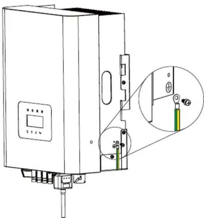
natural_image
Technical line drawing of a mechanical device with an inset close-up showing internal components (no text or symbols)Pic 5.11The installation of the shell ground wire
Warning:
Inverter has built-in leakage current detection circuit, If an external leakage current protection device is connected, its operating current must be greater than 300 mA or higher, otherwise inverter may not work properly.
5.4 Max. over current protection device
In order to protect the inverter AC connection, it is recommended to install a circuit breaker to prevent overcurrent. See table 5.3 below.
| Inverter | Rated output voltage(V) | Rated output current(A) | Current for protection device(A) |
| SUN-15K-G03 23 | 0 3021.8 | ||
| SUN-17K-G03 23 | 0 3024.6 |
Table 5.3 Recommended current protector specifications
5.5 Inverter monitoring connection
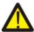
Inverter has the function of wireless remote monitoring. The inverter with Wi-Fi function is equipped with Wi-Fi Plug to connect the inverter and network. Wi-Fi Plug's operation, installation, Internet access, APP downloading and other processes are detailed in the instructions.
flowchart
graph TD
    A["WIFI"] --> B["Router"]
    C["GPRS"] --> B
    D["PC"] --> E["Internet"]
    F["Phone"] <--> B
    G["Web Server"] <--> E
    B <--> E
Pic 5.12 Internet monitoring solution
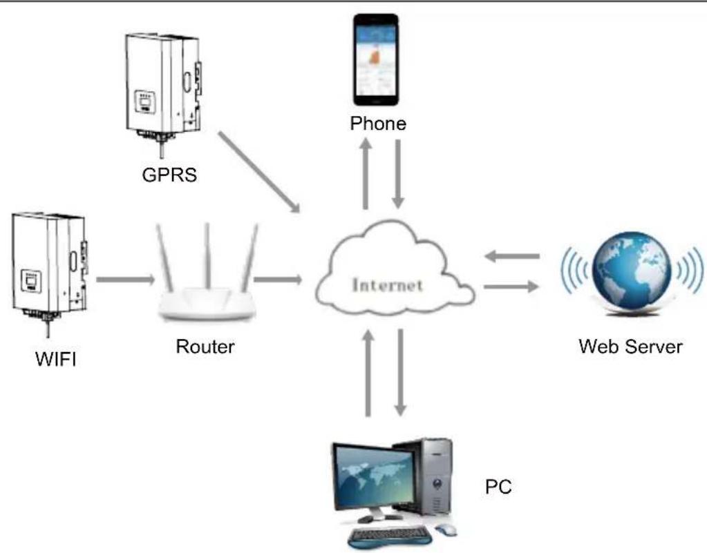
5.6 Installation of datalogger
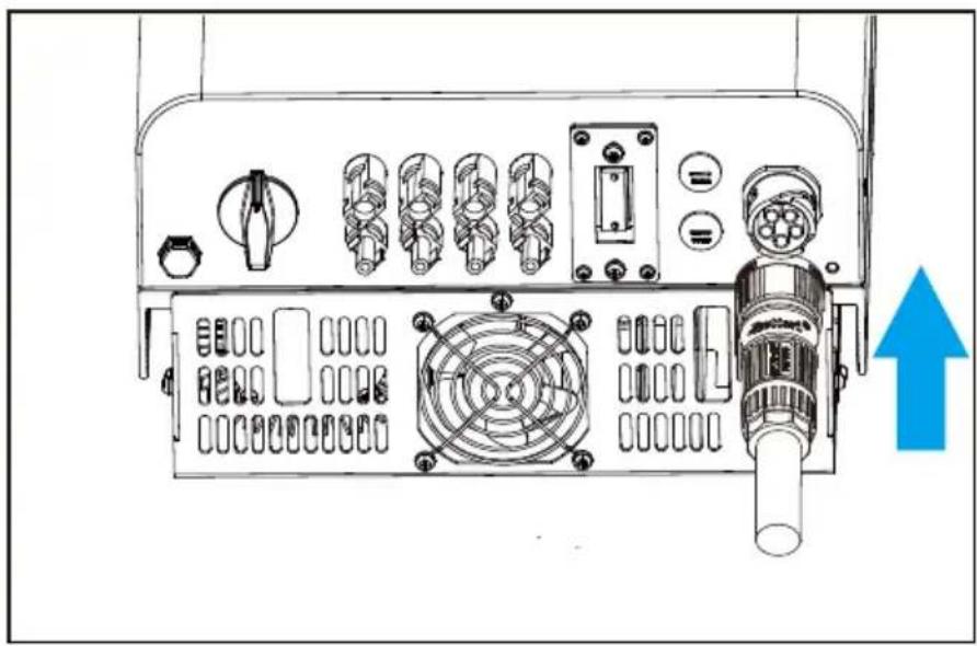
When the inverter is out of the factory, the installation location of dataloggeris sealed by a sealed plate as shown in Picture 5.13. When installing the datalogger, remove the sealing plate, replace it with the sealing plate with square hole in the accessories, and tighten the screws. Insert the datalogger into the interface and fix it with a screw. The configuration of the datalogger needs to be performed after various electrical connections have been completed and the inverter DC power on. When the inverter is on the DC power, it is determined whether the datalogger is normally electrified (The LED light shines out of the shell).
natural_image
Diagram of an electronic device front panel with ports, switches, and a blue arrow indicating a specific component (no text or labels present)Pic 5.13 Datalogger installation diagram
5.7 Configuration of Datalogger
For the configuration of datalogger, please refer to illustrations of the datalogger.
6. Startup and Shutdown
Before starting the inverter, make sure that the inverter can meet the following conditions, otherwise it may result in fire or damage to the inverter. In this case, we do not undertake any responsibility. At the same time, to optimize the system configuration, it is recommended that the two inputs be connected to the same number of photovoltaic modules.
a). The maximum open voltage of each set of photovoltaic modules shall not exceed 1000Vdc under any conditions.
b). Each input of the inverter better use the same type of photovoltaic module in series.
c). Total output power of pv shall not exceed the maximum input power of inverter, each photovoltaic modules shall not exceed the rated power of each channel.
6.1 Start up the inverter
When start up the three phase string inverter, should fellow below steps:
-
First switch on the AC breaker.
-
Turn on the DC switch of the photovoltaic module, and if the panel provides sufficient starting voltage and power, the inverter will start.
-
When the ac voltage and DC voltage are normal, the inverter start-up is ready to begin. The inverter will first check the internal parameters and the grid parameters, while the liquid crystal will show that the inverter is self-checking.
-
If the parameter is within acceptable range, the inverter will generate energy. NORMAL indicator light is on.
6.2 Inverter Shutdown
Must follow below steps while shutting down the inverter:
-
Switch off the AC breaker.
-
Wait for 30 seconds, turn off the DC switch (if any), or simply disconnect the DC input connector. The inverter will close the LCD and all LED within two minutes.
7 Zero export function via SUN limiter
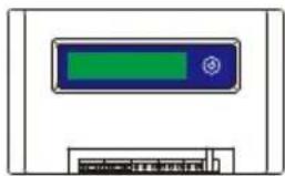
The inverter has external zero export function. This function is optional. It can collect counter-current power to control the output power of the inverter, so that the power of inverter and load can be offset, and the excess power will not be fed back to the grid. If you purchase the inverter with zero export function, an external zero export device ( SUN limiter or energy meter) will be included in the package which is necessary for the function. The SUN limiter shows as Pic 7.1. You can see corresponding line mark next to the green interface. The green terminals on the left are the interface of three-phase AC line (L1, L2, L3) and N Line (N), and the right are the interface between three sets of current sensor and one set of control terminals. SUN limiter will collect voltage and current from these interfaces and send control signals to the inverter.
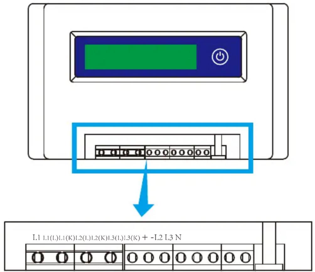
Pic 7.1 SUN Limiter view
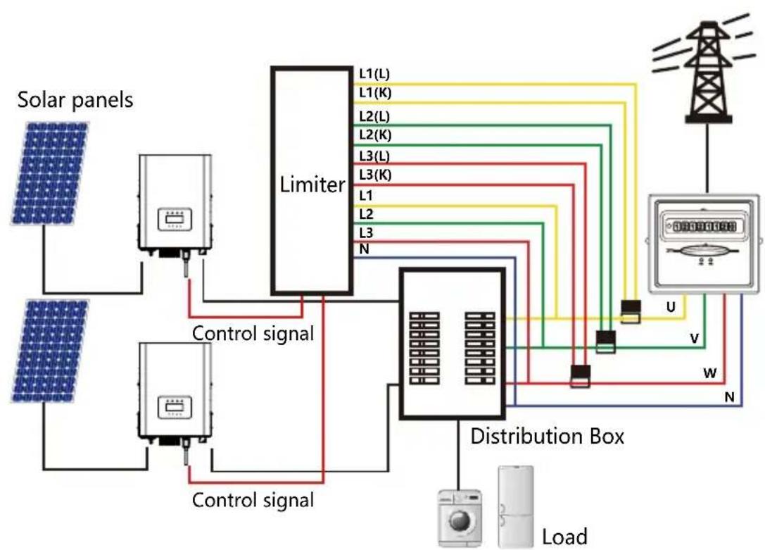
7.1 SUN Limiter function wiring diagram
When you are reading this, we believe that you have completed the connection according to the requirements of chapter 5, if you has been running your inverter, and you want to use the limiter function, please turn off AC and DC switch of the inverter, and wait for 5 minutes until the inverter completely discharged. In order to make it easier for you to use the limiter function, we have specifically given the wiring diagram, as shown in Picture 7.2, the yellow/green/red live line (L1,L2,L3) connected to the utility grid live line (U/V/W), blue line means the neutral line.
We recommend installing an AC switch between the inverter outlet and the utility grid, the specs of the AC switch is determined by the load capacity. The AC switch we recommend to connect to the inverter output refer to Table 5.2.
flowchart
graph TD
    A["Solar panels"] --> B["Control signal"]
    C["Solar panels"] --> D["Control signal"]
    B --> E["Limiter"]
    D --> E
    E --> F["Distribution Box"]
    G["Load"] --> H["Sensor"]
    I["U"] --> F
    J["V"] --> F
    K["W"] --> F
    L["N"] --> F
    M["L1(L), L1(K), L2(L), L2(K), L3(L), L3(K)"] --> F
    N["L1, L2, L3"] --> F
    O["Ground"]
Pic 7.2 Wiring diagram
7.2 Connect the SUN limiter to inverter
The SUN limiter will measure the voltage and current of three phases separately, and this manual only introduces the installation steps of one phase, the other two phases are the same. The specific installation steps are as follows:
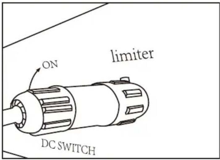
(1) Connect SUN limiter to the grid. Connected to the grid is to measure the voltage of grid. Before connect to the grid, please turn off the switch to avoid the risk of electric shock. Choose one wire from the bottom of the three-phase DC switch. (any phase of U,V,W) to connect with L1 terminal, then tighten the line with a screwdriver.
(2) Connect SUN limiter to clamp senor. Clamp senor can measure the current of the AC side, it should be connected to the front side of the load (domestic appliance ect.) to achieve this function. Only when the SUN limiter collects the voltage and current of the same phase can it judge the power of the phase. So the clamp senor should be connected to the same phase as the before. Open the side buckle of the clamp senor, then clamp the senor to the AC line on the DC switch, the arrow direction on the senor should towards that of the load. The clamp senor has two lines (shown as below), and the white line corresponds to K terminal, black line corresponds to L terminal. Connect the white line to the L1(L) and L1(K) terminal refer to the line mark of the SUN limiter and tighten the line with screwdriver. This is the whole installation process of one phase.
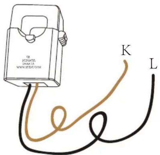
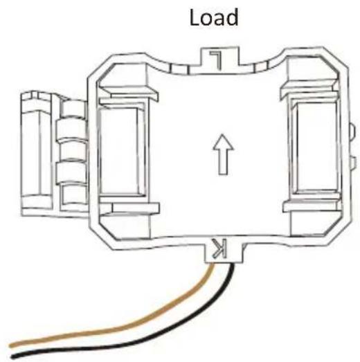
Pic 7.3 Clamp Senor Pic 7.4 Clamp Senor internal arrow
(3) After you finish the installation in process 1 and 2, connect the N line (N) to the N terminal of the limiter and tighten the line.
(4) Connect the control line. There are two numbers 1 and 2 on the interface of SUN limiter, and the same on the waterproof terminal of the inverter. Twist the waterproof terminal and connect the red line to number 1 and black line to number 2 shown as the picture. After that connect the terminal to the interface of the SUN limiter. The other side of the line should be connected to the control terminal.
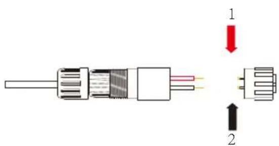
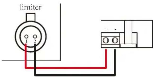
Pic 7.5 Waterproof terminal Pic 7.6 Connect limiter to inverter
Pic 7.7 Connect terminal to inverter
7.3 Use of zero export function
When the connection is completed, the following steps should be referenced to use this function:
- Turn on the AC switch
- Turn on the DC switch, Waiting inverter LCD lighting up
- Press Enter button on the LCD panel in the main interface into the menu options, select [parameter setting] to Enter setup submenu, and then select [running parameters] as shown in figure 7.8, at this time please Input the default password 1234 through pressing the button [up down, confirm], enter the operation parameter setting interface, Shown as figure:
System Param << Run Param
*Fun-GFDI OFF
OFF <<Limite
Pic7.8 Parameter setting
Pic 7.9 Limit switch
- Operate the button [up down], move setting cursor to limit function and press the button [enter]. At this time you can turn on or turn off the limit function by choosing [up down] button, please press [enter] button to confirm when setting done.
- Move the cursor to [confirm], press ENTER to save the settings and exit the running parameters page, otherwise the settings are invalid.
- If set up successfully, you can return to the menu interface, and display the LCD to [home page] by press the [up down] button. If it displayed as [utility power], the limiter function settings will be completed. Shown as picture 7.10.
*Fun-GFDI OFF
FF Utility Power: ON <<Limiter 20W
* This item is not available for some FW verison
Pic 7.10 Limiter function turn on
- [utility power] showing positive means grid power is consuming energy, and there is no backflow. If [utility power] shows negative, which means there's excess PV energy flows to grid or current transformer arrow direction is in wrong direction. Please read more on chapter 7.9.
- After properly connection is done, wait for inverter starting. If the power of the PV array meets the current power consumption, the inverter will maintain a certain output to counteract the power of the grid without backflow.
7.4 Zero-export function (Option)
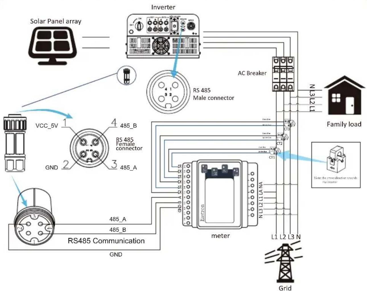
The string inverter supports zero-export function via Energy meter / SUN-Limiter. Based on continuously data communication, once the Limiter or energy meter detects power export to the grid, it will send the information to the inverter and then inverter will ramp down its active power according to match the load demand and achieve zero export. The Zero-export function is optional. If you buy the inverter with zero-export function via energy meter, energy meter will be included in the package which is necessary for zero-export function.
7.4.1 Zero-export function via energy meter
When you are reading this, we believe that you have completed the connection according to the requirements of chapter 5, if you have been running your inverter at this time, and you want to use the zero-export function, please turn off AC and DC switch of the inverter, and wait for 5 minutes until the inverter completely discharged. Please follow below Picture 7.11 to connect the energy meter.
For system wiring diagram, the red line refers to L line (L1, L2, L3), the black line refers to the neutral line (N). Connecting energy meter RS485 cable to inverter's RS485 port. It's recommended to install an AC switch between the inverter and the utility grid, the specs of the AC switch are determined by the power of load.
If there is no integrated DC switch inside the inverter you purchased, we commend you to connect the DC switch. The voltage and current of the switch depend on the PV array you access.
RS 485
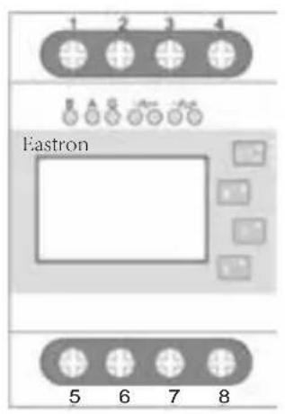
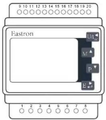
Pic 7.11 Eastron meterEastron SDM630-Modbus V2
flowchart
graph TD
    A["Solar Panel array"] --> B["Inverter"]
    B --> C["AC Breaker"]
    C --> D["Family load"]
    D --> E["meter"]
    E --> F["Grid"]
    B --> G["VCC_5V"]
    G --> H["GND 1"]
    H --> I["RS485 Communication"]
    I --> J["GND 2"]
    J --> K["RS485 Female connector"]
    K --> L["RS485 Male connector"]
    L --> M["L1 L2 L3 N"]
    M --> N["N L3 L2 L1"]
    N --> O["L1 L2 L3 N"]
    O --> P["L1 L2 L3 N"]
    P --> Q["L1 L2 L3 N"]
    Q --> R["L1 L2 L3 N"]
Pic 7.12 Connection diagram of Eastron meter
Eastron SDM630MCT
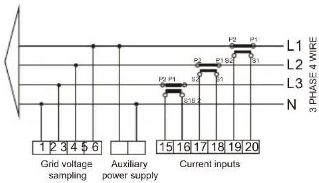
flowchart
graph TD
    A["Grid voltage sampling"] --> B["Current inputs"]
    C["Auxiliary power supply"] --> D["Current inputs"]
    B --> E["L1"]
    B --> F["L2"]
    B --> G["L3"]
    B --> H["N"]
    style A fill:#f9f,stroke:#333
    style C fill:#ccf,stroke:#333
    style B fill:#cfc,stroke:#333
    style D fill:#fcc,stroke:#333
    style E fill:#ffc,stroke:#333
    style F fill:#ffc,stroke:#333
    style G fill:#ffc,stroke:#333
    style H fill:#ffc,stroke:#333
RS 485
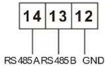
Pic 7.13 Eastron meter
flowchart
graph TD
    A["Solar Panel array"] --> B["Inverter"]
    B --> C["RS 485 Male connector"]
    C --> D["AC Breaker"]
    D --> E["Family load"]
    E --> F["Grid"]
    G["VCC_5V"] --> H["RS 485 Female connector"]
    H --> I["GND"]
    I --> J["RS485 Communication"]
    J --> K["GND"]
    K --> L["Grid"]
    M["Note: the crowd direction towards the inverter"] --> N["L1 L2 L3 N"]
    N --> O["L1 L2 L3 N"]
    P["N L3 L2 L1"] --> Q["AC Breaker"]
    Q --> R["AC Breaker"]
    S["AC Breaker"] --> T["AC Breaker"]
    U["AC Breaker"] --> V["AC Breaker"]
    W["AC Breaker"] --> X["AC Breaker"]
    Y["AC Breaker"] --> Z["AC Breaker"]
Pic 7.13 Connection diagram of Eastron meter
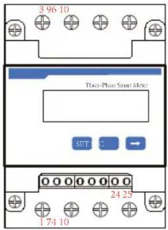
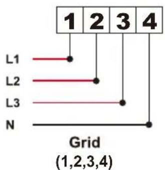
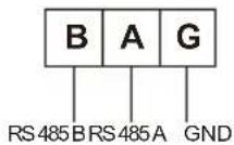
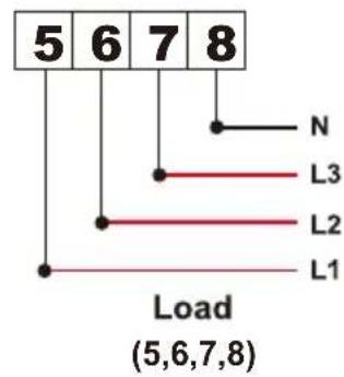
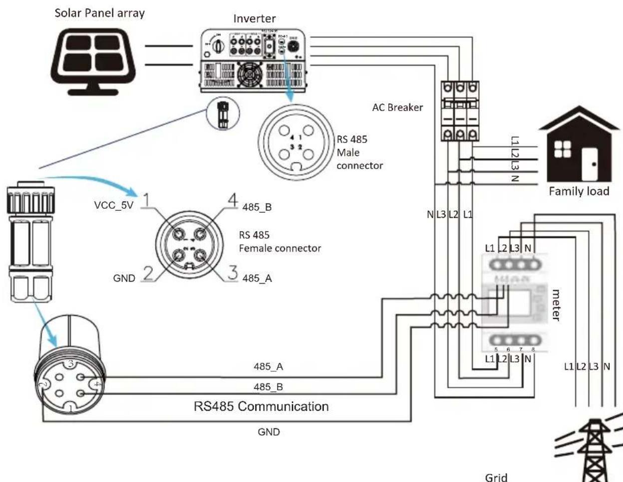
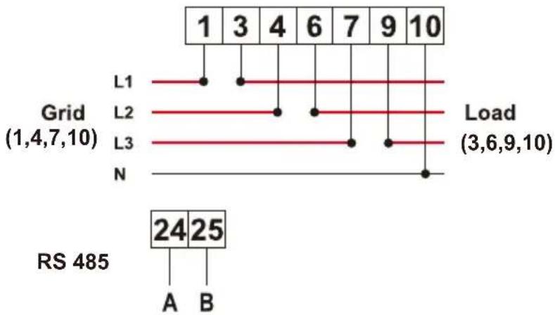
CHNT DTSU666
line
| Grid | Load | | :--- | :--- | | L1 | 1 | | L2 | 3 | | L3 | 4 | | N | 6 | | 1 | 7 | | 9 | 9 | | 10 | 10 | | RS 485 | 24 |Pic 7.14 CHINT meter
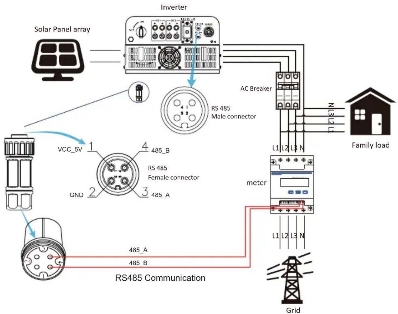
flowchart
graph TD
    A["Solar Panel array"] --> B["Inverter"]
    B --> C["RS 485 Male connector"]
    C --> D["AC Breaker"]
    D --> E["meter"]
    E --> F["Grid"]
    G["VCC_5V"] --> H["RS 485 Female connector"]
    H --> I["RS485 Communication"]
    I --> J["Grid"]
    K["Family load"] --> L["L1 L2 L3 N"]
    L --> M["N 3 L1 L2 N"]
    style A fill:#f9f,stroke:#333
    style B fill:#ccf,stroke:#333
    style C fill:#cfc,stroke:#333
    style D fill:#fcc,stroke:#333
    style E fill:#cff,stroke:#333
    style F fill:#ffc,stroke:#333
    style G fill:#f9f,stroke:#333
    style H fill:#ccf,stroke:#333
    style I fill:#cfc,stroke:#333
    style J fill:#fcc,stroke:#333
Pic 7.15 Connection diagram of CHINT meter
Warning:
Ensuring grid input cables connect 1/4/7/10 port of energy meter, and inverter AC output cables connect 3/6/9/10 port of energy meter when connecting.
7.4.2 Use of zero-export function
When the connection is completed, the following steps should be referred to use this function:
- Turn on the AC switch.
- Turn on the DC switch, waiting for the inverter's LCD is turned on.
- Press Enter button on the LCD panel in the main interface into the menu options, select [parameter setting] to enter setup submenu, and then select [running parameters] as shown in picture 7.13, at this time please input the default password 1234 through pressing the button [up down, enter], enter the operation parameter setting interface, shown as picture 7.14.
System Param << Run Param
Island OFF
OFF << Mete
Pic 7.14 Meter switch Pic 7.13 Paramet
- Operate the button [up down], move setting cursor to energy meter and press the button [enter]. At this time you can turn on or turn off the energy meter by choosing [up down] button, please press [enter] button to confirm when setting done.
- Move the cursor to [OK], press [enter] to save the settings and exit the running parameters page, otherwise the settings are invalid.
- If set up successfully, you can return to the menu interface, and display the LCD to [home page] by press the [up down] button. If it displays [meter power XXW], the zero-export function setting is completed. Shown as picture 7.15.
Meter Power: 20W
Pic 7.15 Zero-export function via energy meter turn on
- Meter power XXW shows positive means grid is supplying the load, and no power fed into grid. if meter power shows negative, it means PV energy is being sold to grid or energy meter wiring connection has problem.
- After properly connection is done, wait for inverter starting. If the power of the PV array meets the current power consumption, the inverter will keep a certain output to counteract the power of the grid without backflow.
7.5 Notes while using zero export function
For your safety and the operation of limiter function of the inverter, we put forward the following suggestions and precautions:
Warning:
Under zero export mode we strongly recommend that the two PV arrays are formed by the same number of PV panels of the same size, which will make the inverter more responsive to limit the power.
Safety Hint:
While the utility power is negative and inverter has no output power, that means the orientation of the current sensor is wrong, please turn off the inverter and change orientation of the current sensor.
(when using SUN limiter, the arrow of current sensor points to the load)
High Temperature Hazard:
When using SUN limiter, the current sensor of limiter function needs to be clamped on the fire line of the grid connected to the inverter, otherwise inverter cannot able to normal operate.
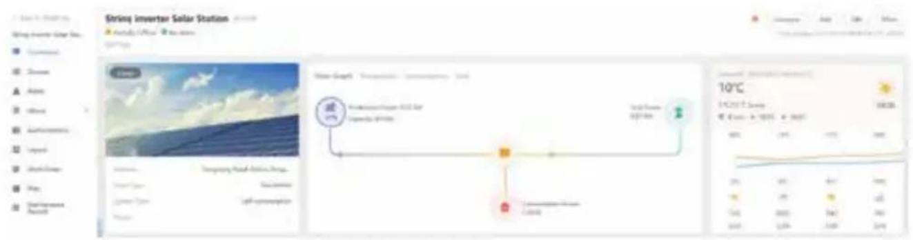
7.6 How to browse the load power of your PV grid-tie plant on monitoring platform?
If you want to browse load power of the system and how much energy (KWH) does it export to grid(inverter output power is used to power the load firstly and then the surplus energy will feed into grid). You also need to connect the meter according to above diagram. After the connection completed successfully, the inverter will show the load power on the LCD. But please don't setup "Meter ON". Also, you will be able to browse the load power on the monitoring platform. The plant setting method as below description.
Firstly, go to the solarman platform(https://pro.solarmanpv.com, this link is for solarman distributor account; or https://home.solarmanpv.com, this link is for solarman end user account;) plant home page and click "edit"
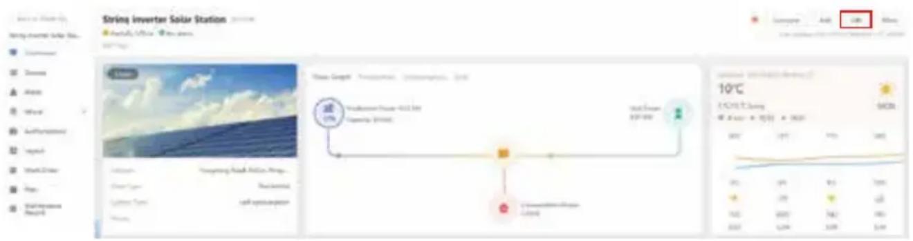
And then choose your system type as "Self-consumption"

Secondly, go to plant page, if it shows the PV power, load power and grid power, which means the configuration is correct.
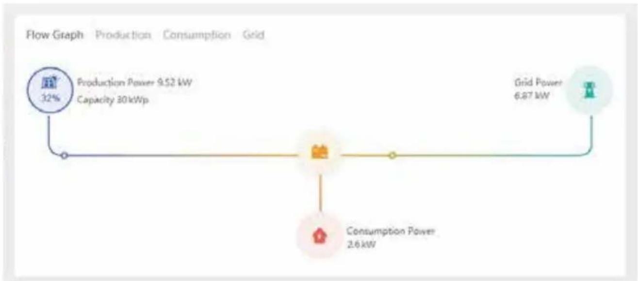
flowchart
graph LR
    A["Production Power 9.52 kW\nCapacity 30kWp"] --> B["Grid Power 6.87 kW"]
    C["Consumption Power 2.6 kW"] --> B
8. General Operation
During normal operation, the LCD shows the current status of the inverter, including the current power, total generation, a bar chart of power operation and inverter ID, etc. Press the Up key and the Down key to see the current DC voltage, DC current, AC voltage, AC current, inverter radiator temperature, software version number and Wifi connection state of the inverter.
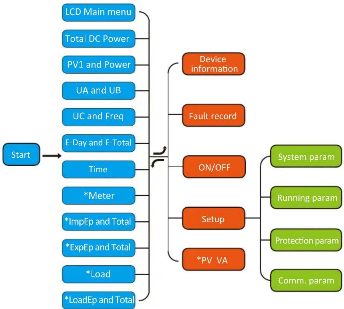
flowchart
graph TD
    A["Start"] --> B["LCD Main menu"]
    A --> C["Total DC Power"]
    A --> D["PV1 and Power"]
    A --> E["UA and UB"]
    A --> F["UC and Freq"]
    A --> G["E-Day and E-Total"]
    A --> H["Time"]
    H --> I["*Meter"]
    I --> J["*ImpEp and Total"]
    J --> K["*ExpEp and Total"]
    K --> L["*Load"]
    L --> M["*LoadEp and Total"]
    B --> N["Device information"]
    C --> O["Fault record"]
    D --> P["ON/OFF"]
    E --> Q["Setup"]
    F --> R["*PV VA"]
    P --> S["System param"]
    Q --> T["Running param"]
    R --> U["Protection param"]
    R --> V["Comm. param"]
*Note: These parameters will be available after the meter is connected successfully. Otherwise, it won't show.
Pic 8.1 LCD operation flow chart
8.1 The initial interface
From the initial interface, you can check PV power, PV voltage, grid voltage, inverter ID, model and other infomation.
Power: 0W State: Standby
Power: 0W State: Com.Error
Pic 8.2 The initial interface
Press UP or Down, you can check inverter DC voltage, DC current, AC voltage, AC current and inverter temperature.
PV1: 0.0V 0.0A
Pic 8.3 PV input voltage and current information
UA: 234V 0.0A UB: 0V 0.0A
Pic 8.5 Grid voltage and current information
Pic 8.9 Electrical energy
ExpEp: 0.00KWh Total : 0.00KWh
Pic 8.10 Electrical energy
Load Power: 0W
Pic 8.4 Load power
UC: 0V 0.0A Freq: 0.00Hz
Pic 8.6 Grid voltage and frequency
Meter Power: 0W
Pic 8.8 Meter power
ImpEp: Daily energy purchased from grid; Total: Total energy purchased from grid.
ExpEp: Daily energy sold to grid; Total: Total energy sold to grid.
LoadEp: 0.00KWh Total : 0.00KWh
Pic 8.11 Load consumption
E-Day : 0Wh E-Total : 134KWh
Pic 8.12 PV generation
LoadEp: Daily consumption; Total: Total energy consumption.
E-Day: Daily generation; E-Total: Total generation.
8.2 Submenus in the Main Menu
There are five submenus in the Main Menu.
8.2.1 Device information
You can see the LCD software Ver0201 and control board software Ver1970. In this interface, there are parameters such as rated power communication addresses.
Device Info. << Fault Record
GL1030 SN-01 ID:0000000012
ID:0000000012 Ver0201 Ver1970
Pic 8.13 Device information
8.2.2 Fault Record
It can keep Eight fault records in the menu including time, customer can deal with it depends on the error code.
Device Info. Fault Record <<
1 F35 200521 15 2 F56 200519 17
Pic 8.14 Fault Record
8.2.3 ON/OFF setting
ON / OFF << Setup
Turn ON << Turn OFF
Turn ON
OK << Cancel
Turn OFF
OK << Cancel
Pic 8.15 ON/OFF setting
When the inverter is turned off, it stops working immediately, and go to standby mode and then will go to self-test program again. If it passed the self-test, it will start to work again.
8.2.4 PV VA setting
Setup PV VA <<
Branch 1 : 0.0A
Branch 2 : 0.0A
Pic 8.16 PV String current
Each PV string current and this function is optional.
8.2.5 Parameter setting
There are five submenus in the setup. Setting includes system param, run param, protect param, comm: param. All of these information for maintenance reference.
Setup << PV VA
System Param << Run Param
Protect Param Comm. Param <<
Pic 8.17 Submenus of the parameter setup
8.3 System param setting
System Param includes time set, language set, display set and factory reset.
Time Set << Language Set
Display Set Factory Reset <<
Pic 8.18 System Param
20200522 OK 08:11:21 Cancel
Pic 8.19 Time
English << Angielski
Pic 8.20 Language
Bright Keep << Delay time 055
Delay time 055 OK << Cancel
Pic 8.21 LCD Screen settings Pic 8.22 Delay time set
Confirm Reset << Cancel
Pic 8.23 Reset to factory setting
8.4 Running param set
Note:
Password required-- only for access-authorized engineer. Un-authorized access may avoid the warranty. The initial password is 1234.
PassWord
* * * *
Pic 8.24 Password
8.4.1 ActiveP set
ActiveP 0%
ReactiveP 0% <<
Pic 8.25
Adjust the output active power in % ReactiveP: Adjust reactive power output in %
PF 1.000
Fun_ISO OFF <<
Pic 8.26
Fun_ISO: Insulation resistance detection
Fun_RCD OFF
SelfCheck 0s <<
Pic 8.27
Fun_RCD: Residual current detection Self-check: Inverter's self-check time. The default value 60s
Island OFF
Meter OFF <<
Pic 8.28
Island: Anti-islanding protection Meter: Energy meter. If inverter will connect meter, then set here to ON
Limiter ON
Feed-in 50% <<<
Pic 8.29
Limiter: If inverter will connect SUN limiter, then set here to ON
Feed_In %: it is used to deploy how much power can be feed into grid.
For example, Feed_in=50% of the 17KW model, which means Max. 8.5KW power can be feed into grid. And, this parameter is valid only after connecting a meter and the meter function is "ON".
MPPT Num 0 <<
Pic 8.30
8.5 Protect Param
Note:
Engineer Only.
We will set the param depends on the safety requirements, so customers don't need to reset it. The password is same as 8.4 Running param
PassWord

Pic 8.31 Password
00 INMETRO
00 EN50549 <<
00 CUSTOM
00 VDE_4105 <<
00 CEI_0_21
00 G98_G99 <<
00 EN50438
00 IEC61727 <<
00 UTE_C15
00 RD_1699 <<
00 AS4777
OK << Cancel
Note:
Engineer only.
AC OverVoltage <<
U1: 260.0V
Tripping Time1 <<
Time1: 2000ms
AC LowVoltage <<
U1: 195.5V
Tripping Time1 <<
Time1: 2000ms
AC OverVoltage << U2: 265.0V
Rated Voltage << 127/220V
OK << Cancel
Pic 8.32 "CUSTOMIZED"
Please set the proper grid parameters according to the requirements of your current country's grid regulations. If you are not clear about it, please consult your installer.
8.6 Comm. param set
Address: 16 << BaudRate: 9600
Pic 8.33 Comm. Param
9. Repair and Maintenance
String type inverter doesn't need regular maintenance. However, debris or dust will affect heat sink's thermal performance. It is better to clean it with a soft brush. If the surface is too dirty and affect the reading of LCD and LED lamp, you can use wet cloth to clean it up.
Warning:
When the device is running, the local temperature is too high and the touch can cause burns. Turn off the inverter and wait for it cooling, then you can clean and maintain.
Warning:
No solvent, abrasive materials or corrosive materials can be used for cleaning any parts of the inverter.
10. Error information and processing
Inverter has been designed in accordance with international grid tied standards for safety, and electromagnetic compatibility requirements. Before delivering to the customer the inverter has been subjected to several tests to ensure its optimal operation and reliability.
10.1 Error code
If there is any failure, the LCD screen will display an alarm message. In this case, the inverter may stop feeding energy into the grid. The alarm description and their corresponding alarm messages are listed Table 10.1.
| Error code Description Ongrid - Three Phase | ||
| F01 DC input polarity reverse fault Check the PV input polarity. | ||
| F02 | DC insulation impedance permanent fault | Check the grounding cable of inverter. |
| F03 | DC leakage current fault | Hardly appear the code. Never ever happened so far. |
| F04 | Ground fault GFDI Check the solar panel output connection. | |
| F05 | Read the memory error | Failure in reading memory (EEPROM). Restart the inverter if the fault still exists, contact your installer or Deye service. |
| F06 | Write the memory error | Failure in writing memory (EEPROM). Restart the inverter if the fault still exists, contact your installer or Deye service. |
| F07 | GFDI blown fuse | Hardly appear the code. Never ever happened so far. |
| F08 | GFDI grounding touch failure | Hardly appear the code. Never ever happened so far. |
| F09 | IGBT damaged by excessive drop voltage | Hardly appear the code. Never ever happened so far. |
| F10 | Auxiliary switch power supply failure | 1. It tells the DC 12V is not existed.2. Restart the inverter, if the fault still exists, please contact your installer. |
| F11 | AC main contactor errors | Hardly appear the code. Never ever happened so far. |
| F12 | AC auxiliary contactor errors | Hardly appear the code. Never ever happened so far. |
| F13 | Working mode changed/Grid mode changed | 1. Lost of one phase or AC voltage detection circuit or relays not closed (old inverter not have relays detection function).2. Restart the inverter, if the error still exists, please contact your installer or Deye service. |
| F14 | DC firmware over current | Hardly appear the code. Never ever happened so far. |
| F15 | AC firmware over current | 1. The internal AC sensor or detection circuit on control board or connection wire may loose.2. Restart the inverter, if the error still exists, please contact your installer or Deye service. |
| F16 | GFCI(RCD) Ac leakage current fault | 1. This fault means the average leakage current is over 300mA. Check whether DC power supply or solar panels is ok, then check 'Test data'-> 'diL' value is about 40; Then check the leakage current sensor or circuit (the following picture). Checking test data needs using big LCD.2. Restart the inverter, if the error still exists, please contact your installer or Deye service. |
| F17 | Three phase current, over-current fault | Hardly appear the code. Never ever happened so far. |
| F18 | AC over current fault of hardware | 1. Check AC sensor or detection circuit on control board or connection wire.2. Restart the inverter or factory reset, if the error still exists, please contact your installer or Deye service. |
| F19 | Hardly appear the code. Never ever happened so far.All hardware | |
| Error code | Description Ongrid - Three Phase | |
| F20 | DC over current fault of the hardware | 1. Check whether solar panel output current is within the allowed range.2. Check DC current sensor and its detection circuit.3. Check if the inverter FW version is suitable for the hardware.4. Restart the inverter, if the error still exists, please contact your installer or Deye service. |
| F21 | DC leakage flow fault | Hardly appear the code. Never ever happened so far. |
| F22 | Crash stop (if there is a stop button) | Contact your installer for help. |
| F23 | AC leakage current is transient over current | 1. This fault means the leakage current is above 30mA suddenly. Check whether DC power supply or solar panels is ok, then check 'Test data'-> 'diL'value is about 40; Then check the leakage current sensor or circuit. Check test data needs using big LCD.2. Restart the inverter, if the fault still exists, contact your installer or Deye service. |
| F24 | DC insulation impedance failure | 1. Check Vpe resistance on main board or detection on control board. Check PV panels is OK. Many times this issue is the PV problem.2. Check whether the PV panel (aluminum frame) is grounded well and inverter is grounded well. Open the cover of inverter and then check the inside ground cable is fixed well on the shell.3. Check if the AC/DC cable, terminal block are shorted to ground or the insulation is damaged.4. Restart the inverter, if the fault still exists, contact your installer or Deye service. |
| F25 | DC feedback fault | Hardly appear the code. Never ever happened so far. |
| F26 | The DC busbar is unbalanced | 1. Check whether the 'BUSN' cable or driver board power supply cable is loose.2. Restart the inverter, if the fault still exists, contact your installer or Deye service. |
| F27 | DC end insulation error | Hardly appear the code. Never ever happened so far. |
| F28 | Inverter 1 DC high fault | Hardly appear the code. Never ever happened so far. |
| F29 | AC load switch failure | Hardly appear the code. Never ever happened so far. |
| F30 | AC main contactor failure | 1. Check relays and AC voltage of relays.2. Check relays driver circuit. Check if the software is not suitable for this inverter. (Old inverter not have relays detection function)3. Restart the inverter, if the fault still exists, contact your installer or Deye service. |
| F31 | Dc boost soft start | 1. At least one Relay can't be closed. Check relays and its driver signal. (Old inverter not have relays detection function)2. Restart the inverter, if the fault still exists, contact your installer or Deye service. |
| F32 | Inverter 2 dc high fault | Hardly appear the code. Never ever happened so far. |
| F33 | AC over current | Hardly appear the code. Never ever happened so far. |
| F34 | AC current over load | Hardly appear the code. Never ever happened so far. |
| F35 | No AC grid | 1. Check AC grid voltage. Check AC voltage detection circuit. Check if the AC connector in good condition. Check whether the AC grid is normal in voltage.2. Restart the inverter, if the fault still exists, contact your installer or Deye service. |
| F36 | AC grid phase error | Hardly appear the code. Never ever happened so far. |
| F37 | AC three-phase voltage unbalance failure | Hardly appear the code. Never ever happened so far. |
| F38 | AC three-phase current unbalance failure | Hardly appear the code. Never ever happened so far. |
| F39 | AC over current(one cycle) | 1. Check AC current sensor and its circuit.2. Restart the inverter, if the fault still exists, contact your installer or Deye service. |
| F40 | DC over current | Hardly appear the code. Never ever happened so far. |
| F41 | AC Line W,U over voltage | Check the AC voltage protection setting. And Check if the AC cable is too thin.Check the voltage difference between LCD and meter. |
| F42 | AC Line W,U low voltage | Check the AC voltage protection setting. Check the voltage difference between LCD and meter. Also need to check whether AC cables are all firmly and correctly connected. |
| F43 | AC Line V,W over voltage | Check the AC voltage protection setting.And Check if the AC cable is too thin.Check the voltage difference between LCD and meter. |
| F44 | AC Line V,W low voltage | Check the AC voltage protection setting. Check the voltage difference between LCD and meter. Also need to check whether AC cables are all firmly and correctly connected. |
| F45 | AC Line U,V over voltage | Check the AC voltage protection setting.And Check if the AC cable is too thin.Check the voltage difference between LCD and meter. |
| F46 AC Line | U,V low voltage Check the AC voltage protection setting. | |
| F47 AC Over frequency Check the frequency protection setting. | ||
| F48 AC lower frequency Check the frequency protection setting. | ||
| F49 | U phase grid current DC component over current | Hardly appear the code. Never ever happened so far. |
| F50 | V phase grid current DC component over current | Hardly appear the code. Never ever happened so far. |
| F51 | W phase grid current DC component over current | Hardly appear the code. Never ever happened so far. |
| F52 | AC inductor A, phase current DC current high | Hardly appear the code. Never ever happened so far. |
| F53 | AC inductor B, phase current DC current high | Hardly appear the code. Never ever happened so far. |
| F54 | AC inductor C, phase current DC current high | Hardly appear the code. Never ever happened so far. |
| F55 | DC busbar voltage is too high | 1. Check PV voltage and Ubus voltage and its detection circuit. If the PV input voltage exceeds the limit, please reduce the number of solar panels in series.2. For Ubus voltage, please check the LCD display. |
| Error code Description Ongrid - Three Phase | ||
| F56 | DC busbar voltage is too low | 1. It tells the PV input voltage is low and it always happens in the early morning.2. Check PV voltage and Ubus voltage. When inverter is running, then showing F56, maybe Loss of driver or need update firmware.3. Restart the inverter, if the fault still exists, contact your installer or Deye service. |
| F57 AC reverse irrigation AC reverse irrigation. | ||
| F58 AC grid U over current Hardly appear the code. Never ever happened so far. | ||
| F59 AC grid V over current Hardly appear the code. Never ever happened so far. | ||
| F60 AC grid W over current Hardly appear the code. Never ever happened so far. | ||
| F61 Reactor A phase over current Hardly appear the code. Never ever happened so far. | ||
| F62 Reactor B phase over current Hardly appear the code. Never ever happened so far. | ||
| F63 Reactor C phase over current Hardly appear the code. Never ever happened so far. | ||
| F64 | IGBT heat sink high temperature | 1. Check temperature sensor. Check if firmware is suitable for the hardware. Check if the inverter is its right model.2. Restart the inverter, if the fault still exists, contact your installer or Deye service. |
Table10.1 Error codes and their solutions

Note:
If your string inverter has any of the fault information shown in Table 10-1, and when you reset the machine and still don't solve the problem, please contact our distributor and provide the below details:
- Serial number of the inverter;
- The distributor/dealer of the inverter(if available);
- Installation date;
- The discription of problem(include LCD'error code and LED status indicator lights);
-
Your contact details.
-
Specification
| Model | SUN-15K-G03 | SUN-17K-G03 |
| Input Side | ||
| Max.DC Power(kW) | 19.5 | 22.1 |
| Max.DC Input Voltage(V) | 1000 | |
| Start-up DC Input Voltage(V) | 250 | |
| MPPT Operating Range(V) | 200~850 | |
| Max.DC Input Current(A) | 13+26 | |
| Max. Short Circuit Current (A) | 19.5+39 | |
| Number of MPPT/Strings per MPPT | 2/1+2 | |
| Output Side | ||
| Rated Output Power(kW) | 15 | 17 |
| Max.Active Power(kW) | 16.5 | 18.7 |
| Rated AC Grid Voltage(V) | 220/380, 230/400 | |
| AC Grid Voltage Range(V) | 277 ~ 460Vac (this may vary with grid standards) | |
| Rated Grid Frequency(Hz) | 50/60(Optional) | |
| Operating Phase | Three phase | |
| Rated AC Grid Output Current(A) | 21.8 | 24.6 |
| Max.AC Output Current(A) | 23.9 | 27.1 |
| Output Power Factor | 0.8 leading~0.8 lagging | |
| <3%Grid Current THD | ||
| DC Injection Current(mA) | <0.5% | |
| Grid Frequency Range | 47-52 or 57-62 (optional) | |
| Efficiency | ||
| Max.Efficiency | 98.5% | |
| Euro Efficiency | 97.5% | |
| >99%MPPT Efficiency | ||
| General Data | ||
| Size(mm, W×H×D) | 330×472×202 | |
| 15Weight(kg) | ||
| Topology | Transformerless | |
| <1W(Night)Internal consumption | ||
| Operating temperature | -25 ~ 65°C | |
| Ingress protection IP65 | ||
| Noise Emission(Typical) | <40dB | |
| Cooling Concept | Smart cooling | |
| Max. operation altitude | 2000m | |
| >20 YearsDesigned Lifetime | ||
| Grid Connection Standard | EN50549-1, IEC61727, IEC62116, IEC60068, IEC61683, VDE0126-1-1, RD1699, UNE206006IN, UNE206007-1 IN, UNE217001IN | |
| Operation surrounding humidity 0~100% | ||
| Stafty EMC / Standard | IEC62109-1/-2, IEC61000-6-1, IEC61000-6-3, IEC61000-3-11, IEC61000-3-12 | |
| General Data | ||
| MC-4 mateableDC Connection | ||
| IP65 rated plugAC Connection | ||
| LCD1602Display | ||
| RS485/RS232/Wifi/LANInterface | ||
NINGBO DEYE INVERTER TECHNOLOGY CO., LTD.
Add: No.26-30, South Yongjiang Road, Beilun, 315806, Ningbo, China
Tel: +86 (0) 574 8622 8957
Fax: +86 (0) 574 8622 8852
E-mail: service@deye.com.cn
Web: www.deyeinverter.com
30240301000407 Ver: 2.1, 2021-7
- Grid-tied PV String Inverter
- Contents
- About This Manual
- How to Use This Manual
- Photovoltaic Grid-connected System
- Introduction
- Appearance Introduction
- Parts list
- Safety warnings and instructions
- Safety signs
- Warning:
- Shock Hazard:
- Safety Hint:
- High Temperature Hazard:
- Safety instructions
- Notes for using
- Operation Interface
- Interface View
- Status Indicator
- Buttons
- LCD Display
- Product installation
- Select installation location
- WARNING: Risk of fire
- Inverter Installation
- Procedure shows below:
- Electrical Connection
- DC input terminal connection
- AC input terminal connection
- The connection of the ground line
- Max. over current protection device
- Inverter monitoring connection
- Installation of datalogger
- Configuration of Datalogger
- Startup and Shutdown
- Start up the inverter
- Inverter Shutdown
- Zero export function via SUN limiter
- SUN Limiter function wiring diagram
- Connect the SUN limiter to inverter
- Use of zero export function
- * This item is not available for some FW verison
- Pic 7.10 Limiter function turn on
- Zero-export function (Option)
- Zero-export function via energy meter
- Use of zero-export function
- Meter Power: 20W
- Pic 7.15 Zero-export function via energy meter turn on
- Notes while using zero export function
- How to browse the load power of your PV grid-tie plant on monitoring platform?
- General Operation
- The initial interface
- Power: 0W State: Standby
- Power: 0W State: Com.Error
- Pic 8.2 The initial interface
- Submenus in the Main Menu
- Device information
- Fault Record
- ON/OFF setting
- PV VA setting
- Parameter setting
- System param setting
- Running param set
- Note:
- ActiveP set
- Protect Param
- PassWord
- Comm. param set
- Repair and Maintenance
- Error information and processing
- Error code
- NINGBO DEYE INVERTER TECHNOLOGY CO., LTD.
Brand : Deye
Model : SUN-7K-G03-P
Category : Solar panel