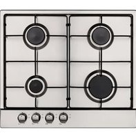
GFC60 - Oven ARC - Free user manual and instructions
Find the device manual for free GFC60 ARC in PDF.


| Product Type | Built-in Electric Oven |
| Brand | ARC |
| Model | GFC60 |
| Dimensions (W x H x D) | 60 cm x 60 cm x 55 cm (approx.) |
| Weight | 35 kg |
| Power Supply | 220-240 V, 50/60 Hz |
| Energy Rating | A+ (approx.) |
| Cooking Functions | Convection, Top Heat, Bottom Heat, Grill, Fan Grill, Defrost, Light |
| Temperature Range | 50°C - 250°C |
| Timer | Digital with minute minder and auto shut-off |
| Interior Capacity | 65 liters (approx.) |
| Cleaning | Enamel interior, removable door and shelves |
| Safety Features | Child lock, cool touch door, auto shut-off, thermal fuse |
| Spare Parts & Repairability | Available: heating elements, thermostat, door gasket, control board |
| Included Accessories | Wire shelf, baking tray, rotisserie kit (if applicable) |
| Manual Availability | Free download in PDF |
Frequently Asked Questions - GFC60 ARC
User questions about GFC60 ARC
0 question about this device. Answer the ones you know or ask your own.
Ask a new question about this device
Download the instructions for your Oven in PDF format for free! Find your manual GFC60 - ARC and take your electronic device back in hand. On this page are published all the documents necessary for the use of your device. GFC60 by ARC.
USER MANUAL GFC60 ARC
Congratulations on purchasing your new product from Home Appliances.
To register your Parts and Labour Warranty, some conditions apply, please refer to your warranty card for more details and contact our Customer Care team on:
1800 444 357
Our Customer Care Centre is there to ensure you get the most out of your appliance. Should you want to learn more about your product and how to use it to its best potential or tips on cleaning, please feel free to call us on the above number.
It is important that you read through the following instruction manual thoroughly to become familiar with the installation and operation of this appliance and ensure optimum performance.
We also carry a complete range of spare parts for all Home Appliance products. For all your spare parts enquiries please contact our learn at Pronto Parts on
1300 306 973
Again, thank you for choosing an appliance brought to you by Home Appliances and we look forward to being of service to you.
Kind regards,
The Management
Home Appliances
Built-in Stainless Steel Gas Cooktop
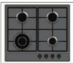
natural_image
Front view of a four-pom stove with four panes and a gas stove (no text or symbols visible)GHS604A-G2CI, GHS604B-G2CI, GH614AS-G2CI, GH614BS-G2CI
Installation and User manual
Content
Safety instructions---- 3
Product description----4
Installation----6
Start using your appliance---- 9
Maintenance and troubleshooting---- 11
This manual explains the proper installation and use of your appliance, please read it carefully before using even if you are familiar with the product. The manual should be kept in a safe place for future reference. In case of failure, only the Authorized Technical Service may repair this hob. Otherwise the guarantee will be null and void.
Warning
General Safety
- The appliance may only be installed and connected by licensed gasfitters / authorized persons.
● Built-in appliances may only be used after they have built-in to suitable built-in units and work surfaces that meet local authority standards.
● Repairs to the appliance must only be carried out by trained registered authorized service persons / engineers. - The technical and identification data for the hob is located on the reference data plate fixed to the underside of the appliance.
- This reference data plate must be consulted before making the electrical connections.
- The electrical connections must be made by specialist installers to the legal and regulatory, requirements in each country.
- If the cable is damaged in any way it must be replaced by the manufacturer or after sale service or by authorized technical staff, to avoid hazard.
Correct Use
- People (including children) who, because of their physical, sensory or mental capabilities or their inexperience or ignorance are not able to use the device safely. should not use this device without supervision or instruction by a responsible person.
- This appliance should be used only for normal domestic cooking and frying of food.
- The appliance must not be used as a work surface or as a storage surface.
- Additions or modifications to the appliance are not permitted.
- Do not place or store flammable liquids, highly inflammable materials or fusible objects (e.g. plastic film, plastic, aluminum) on or near the appliance.
- Do not heat an empty pan on the appliance.
Children's Safety
- The cooking zones will become hot when you cook. Therefore, always keep small children away from the appliance.
- The appliance is not intended for use by young children or infirm persons without supervision.
- Young children should be supervised to ensure that they do not play with the appliance.
Safety During Use
- There is the risk of burns from the appliance if used carelessly.
- Cables from electrical appliances must not touch the hot surface of the appliance or hot cookware.
● Overheated fats and oils can ignite very quickly. Warning! Fire hazard! - Switch the cooking zones off after each use.
- Users with implanted pacemakers should keep their upper body at least 30 cm from
cooking
zones that
are switched
on.
Risk of
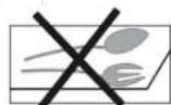
bums! Do not place objects made of metal, such as knives, forks, spoons and saucepan lids on the cooking surface, as they can get hot.
Safety Instructions
Safety When Installation
- DO NOT USE OR STORE FLAMMABLE MATERIALS IN THE APPLIANCE STORAGE DRAWER OR NEAR THIS APPLIANCE.
- DO NOT SPRAY AEROSOLS IN THE VICINITY OF THIS APPLIANCE WHILE IT IS IN OPERATION.
- WHERE THIS APPLIANCE IS INSTALLED IN MARINE CRAFT OR CARAVANS. IT SHALL NOT BE USED AS A SPACE HEATER.
- This hotplate must be installed in accordance with: AS 5601 - Gas Installations (for Australia) – current edition NZS 5261 – Code of Practice for the Installation of Gas Burning Appliances and Equipment (for New Zealand): This standard may not be now current! Local gas fitting regulations AS/NZS 3000 – Electrical Installations (Wiring Rules) Building codes
- Check the gas type label on the underside of the hotplate, adjacent to the gas connection to ensure it corresponds to the installation gas supply. If in doubt contact the supply authority.
Disposing Of The Device

When disposing of the device, do not bring it to regular municipal waste containers. Instead, bring it to electrical and electronic waste recycling and reuse center. A relevant label has been put on the device, its instructions manual, or the package. The device has been manufactured of recyclable material. By bringing old device to recycling collection center, you show that you care about nature. Ask your local environmental care authority for information on location of such facilities.
Gas type label nearby the gas inlet, black color for natural gas, signal red color for ULPG:
Natural Gas
Refer to gas supplier if supply in doubt
Universal LPGas
Refer to gas supplier if supply in doubt

| No. | Model Burner* FSD Pan | supports | Knob position | Total gas consumption | Over view | ||
| 1 | GHS604A-G2CI | 1W+2SR+1A | With | 2 types for option | Front LPG: | 30.5MJ/h |  |
| NG: | |||||||
| 29.5MJ/h | |||||||
| 2 | GHS604B-G2CI | 1R+2SR+1A | With | 2 types for option | Front LPG: | 27.5MJ/h |  |
| 26.0MJ/h | |||||||
| 3 | GH614AS-G2CI | 1W+2SR+1A | With | 2 types for option | Right LPG: | 30.5MJ/h |  |
| NG: | |||||||
| 29.5MJ/h | |||||||
| 4 | GH614BS-G2CI | 1R+2SR+1A | With | 2 types for option | Right LPG: | 27.5MJ/h |  |
| NG: | |||||||
| 26.0MJ/h | |||||||
*Note:
For burner: W=Triple Ring Wok burner, R=Rapid burner, SR=Semi-Rapid burner, A=Auxiliary burner
| Accessory Name | Picture(for reference only, physical unit maybe different) | Quantity | |
| User Manual | 1 | ||
| Sealing tape | 1 roll | ||
| Additional labels | You have additional rating label in accessory bag. suggest attach it onto a surface where it can be read e.g. inside surface of adjacent cupboard | 1 set | |
| Installation clip |  | 4 sets | |
| Screws ST4.2x24 |  | 4 pcs | |
| LPG Injectors | 4 pcs | ||
| Elbow & Washers | 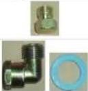 | 1 Elbow, 3 washers | |
| Natural gas regulator |  | 1 | |
Technical Specifications
| Model | Product Dimensions (h x w x d) mm | Cut-out Size (w x d)mm | App'x net weight | Electrical Connection | Rated Input Power |
| CHS604A-G2CI | 120x580x500 | 563 x 483 | 12.5Kgs | 220-240V/50Hz | 0.5W |
| CHS604B-G2CI | 120x580x500 | 563 x 483 | 12.5Kgs | 220-240V/50Hz | 0.5W |
| CH614AS-G2CI | 120x580x500 | 563 x 483 | 12.5Kgs | 220-240V/50Hz | 0.5W |
| GH614BS-G2CI | 120x580x500 | 563 x 483 | 12.5Kgs | 220-240V/50Hz | 0.5W |
Installation
Before Installation:
- Before cutting into any bench tops, ensure the minimum clearances to walls, adjacent surfaces and overhead surfaces required by the relevant gas appliance installation code (see above) will comply. Dimensions are specified in millimeters (mm)
Overhead cupboards and range hood = 650 mm.
Side and rear clearance = 200 mm to any bumer edge.
Overhead exhaust/ceiling fan = 750 mm
Horizontal surfaces adjacent the hob = less than or equal to the hob height.
Ensure there is sufficient clearance to fit the regulator and/or flexible hose connection with the hotplate in the installed position.
When you have installed the hob, make sure that
The GPO(general purpose outlet) must always be in an accessible position.
- The supply connection point, test point and natural gas regulator adjustment screw (for Natural gas installation) are accessible for testing and/or adjustment with the hotplate in the installed position.
TO BE INSTALLED ONLY BY AN AUTHORIZED PERSON.
1. Cupboard Cutting

2. Place Burner Box
Apply the adhesive sealing tape to the underside lip of the burner box. Shown at G opposite.
Place burner box into cutout hole and flt clamping brackets to clamp the hotplate to the bench.

3. Fit Burners And Trivet.
Replace burners and ensure they are correctly repositioned over the ignitor (S) and thermocouple (T). The ignitor (S) must be clean for trouble free sparking. Test burner ignition and burner flame for correct operation, if burner is placed correctly it will not rotate on its supports.
The Triple Ring (Wok) burner (diagrams below) does not fit over the igniter or thermocouple but must be placed on its supports. Make sure trivet is fitted onto its locator on burners and can't rotate after assembled.

3. Electrical Connection
Install a 10 amp general purpose outlet (GPO) in accordance with relevant electrical standards and/or codes of practice applicable.
The power supply cord (supplied) must not touch against any hot surfaces and must be placed so that its temperature does not exceed 75 at any point along its length.
After having installed the hotplate, the GPO must always be in an accessible position.

Wiring diagram
4. Gas Connection
Install in accordance with relevant gas standards and/or codes of practice applicable.
Connect the elbow fitting to the appliance gas manifold connection, and check that seals between the elbow and manifold connection are in place and in good condition.
- For Natural gas: connect the natural gas appliance regulator (pictured opposite) with integral test point using approved gas thread tape or compound to the elbow fitting.
- For Universal LPG: change the natural gas regulator to LPG set by adjusts the spring to make sure the outlet pressure be set at 2.75kPa.
Ensure the supply connection point, test point and natural gas regulator adjustment screw (for Natural gas installation) are accessible for testing and/or adjustment with the holplate in the installed position.
Where a flexible hose assembly is used, ensure it is approved to AS/NZS 1669, Class B. Any hose assembly must be restrained from accidental contact with the flue outlet of an under bench oven. This hose assembly shall be suitable for connection to a fixed consumer piping outlet located as follows:
Hotplates at a point 800 mm to 850 mm above the floor and in the region outside the width of the appliance to a distance of 250 mm.
After connecting to gas, check for leaks using soapy solution, never a naked flame.

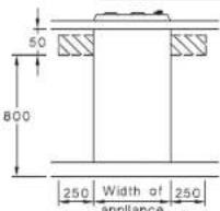

Inlet connection region for flexible hose
Fit the duplicate data plate (supplied in separate bag) on a surface adjacent to the hotplate, for example, the inside of the cupboard door so it is clearly visible for any service technician.
SETTING THE GAS PRESSURE:
Fit a manometer with a 6 mm rubber hose to the test point on the regulator (for natural gas).
Light Triple Ring and Auxiliary burner on and adjust test point pressure to 1.00 kPa. Turn the two burners off and on again and recheck the pressure is same as set previously or adjust as required.
TEST FOR CORRECT OPERATION:
After installation and adjusting burner pressure using test point, each burner ignition and operation must be tested individually and with all burners operating. This testing must be done by the installer before leaving.
NOTE: This adjustment can only be performed by the installer or an authorised service personnel.
The minimum bumer flame is factory adjusted for the gas type stated on the gas type label adjacent to the gas connection and should not require adjustment. Adjustment may be required if the hotplate has been converted from Natural gas to Universal LPG or vice versa.
GAS CONVERSION INSTRUCTIONS:
The manufacturers servicing instructions detail how authorised personnel may convert the hotplate from Natural gas to Universal LPG or from Universal LPG to Natural gas. Contact the manufacturer or agent as required.
| ADJUSTED FOR NATURAL GAS 1.0kPa | ||
| NOZZLES DIAMETER | mm | Gas consumption, MJ/h |
| WOK | 1.70 | 13.0 |
| Rapid | 1.40 | 9.5 |
| SEMI RAPID | 1.10 | 6.0 |
| AUXILIARY | 0.90 | 4.5 |
Replacement of the nozzles must be performed by a qualified person. Once the nozzles have been replaced this label must be affixed to the name plate of the appliances.
Natural Gas regulator is to be fitted and adjusted
| ADJUSTED FOR ULPG 2.75KPa | ||
| NOZZLES DIAMETER | mm | Gas consumption, MJ/h |
| WOK | 0.98 | 13.0 |
| Rapid | 0.90 | 10.0 |
| SEMI RAPID | 0.77 | 6.75 |
| AUXILIARY | 0.55 | 4.0 |
Replacement of the nozzles must be performed by a qualified person. Once the nozzles have been replaced this label must be affixed to the name plate of the appliances.
Change the NG regulator to LPG by a qualified person.
Start Using Your Appliance
GHS604A-G2CI, GHS604B-G2CI

GH614AS-G2C1, GH614BS-G2C1

| Description | Explanation |
| Zone indicators | These show which zone is under control. |
| Flame power | Flame power of the zones. ▲ is the lowest and is the highest. |
The hotplates are fitted with mains powered electronic spark ignitors, so must be connected to mains power supply (i.e. nominal 220\~240 V ac) to operate. If power is not available, the hotplate will still work but the burners will have to be lit with a match or similar.
Depressing the gas control knob of any burner will activate the spark ignition for all burners. To light the burner, turn the gas control knob to the High Flame setting of the burner to be lit, while at the same time depressing the gas control knob to activate the spark ignition.
Once the burner is alight continue to depress the gas control knob for 5 – 10 seconds to allow the flame safeguard to activate. If when you release the gas control knob, the burner flame goes out the flame safeguard has not heated up enough so repeat the ignition procedure after waiting 1 minute for gas to disperse. If problems with burner lighting persist, refer to the TROUBLESHOOTING section of these instructions.
If power is not available, light a match or similar, then turn the gas control knob for the burner to be lit, to the High Flame setting. Once again if problems with burner lighting persist, refer to the TROUBLESHOOTING section of these instructions.
When burner lights, adjust desired flame height. On finishing, turn control knob to off position marked with a black DOT.
BURNER AND UTENSIL CHOICE
The maximum utensil (pan) diameters in millimeters (mm) for each burner are:
- For Natural Gas hotplates
Auxiliary (small) and Semi-Rapid (medium) =
195 mm
Rapid (large) = 230 mm
Triple ring (wok) = 270 mm
- For Universal LPG hotplates
Auxiliary (small), Semi-Rapid (medium) and Rapid (large) = 195 mm
Triple ring (wok) = 230 mm
The minimum ulensil (pan) diameters in millimeters (mm) for each burner are:
Auxiliary (small) = 80 mm
and Semi-Rapid (medium) = 140 mm
Rapid (large) and Triple ring (wok) = 195 mm
For best efficiency and to ensure utensil handle does not overheat, place the utensil centrally on the burner and adjust the flame height so all the flame remains under the utensil.
Maintenance & Troubleshooting
Cleaning and maintenance should be carried out with the appliance cold especially when cleaning the enameled parts. Avoid leaving alkaline or acid substances (lemon juice, vinegar etc.) on the surfaces.
STAINLESS STEEL
The stainless steel hob of the hotplate must be cleaned regularly (e.g. weekly) to ensure long life expectancy of the hotplate.
Ensure hotplate has cooled. Wash down with warm soapy water and rinse with clean water.
Dry with a clean soft cloth. A specialized stainless steel cleaning fluid may be used.
NOTE: Ensure that wiping is done along with the grain of the stainless steel to prevent any unsightly crisscross scratching patterns from appearing.
TRIVETS (UTENSIL SUPPORTS)
Enameled parts must only be washed with a sponge and soapy water or with non-abrasive products. Rinse with clean water. Dry with a clean soft cloth.
BURNERS
Remove trivets from hob. Ensure burners are cool. Remove the burners enameled cap (C) and aluminum burner crown (F).
Wash down with warm soapy water and rinse with clean water. Dry with a clean soft cloth.
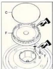
Note: S: Ignition pin T: Thermocouple Use a cotton bud, tooth brush, or some other item to clean out any incrustations or dirt from the four holes marked(H)
The spark gas is 4-6mm.

Replace burners and ensure they are correctly repositioned over the igniter (S) and thermocouple (T). The igniter (S) must be clean for trouble free sparking. Test burner ignition and burner flame for correct operation.
The Triple Ring (Wok) burner (diagrams below) does not fit over the igniter or thermocouple but must be placed on its supports. If burner is placed correctly it will not rotate on its supports.
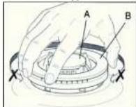
The surface of hob, Ignition Pin(S). Thermocouple (T) and burners need to be cleaned after each time they are used with warm soapy water, rinsed and then dried well to keep them in good condition.
Never clean when the top and components are still warm. Do not use metal or abrasive pads, abrasive powders or corrosive spray products. Never leave vinegar, coffee, milk, salty water, lemon or tomato juice for any length of time on the surfaces.
• To replace gas and electrical components, that are lodged inside the hob, it is enough to remove the work top unscrewing the fixing screws of the burners
- Replace the seal each time you change a tap in order to guarantee a perfect tightness between body and rail.
TROUBLESHOOTING
Servicing of the hotplates must only be done by an authorised service representative (see back of this booklet) and the hotplate must not be modified. Power must be disconnected before any servicing or maintenance is conducted. DO NOT MODIFY THIS APPLIANCE.
It is recommended the hotplate serviced by an authorized person at least every 2 years. This service is not covered by warranty.
Abnormal conditions include:
• Excessively yellow or sooting flame type.
- Flame lifting off the burner ports.
● Flame lighting back into the burner (normally associated with a popping sound).
- Objectionable odour of the flames combustion products.
Should a faulty condition develop in the hotplate that is not described above, refer to the following table first for possible causes and remedies prior to contacting an authorised service representative. Servicing beyond the remedies listed shall only be undertaken by an authorised service representative.
| FAULT | POSSIBLE CAUSE | REMEDY |
| No spark when gas control knob depressed. | No power. | Check plugged in and switched on.Check mains circuit breaker. |
| Loose sparker cable. | Call authorised representative. | |
| Burner not aligned properly. | Remove and re-fit burner. | |
| Burner not lighting when spark ignition working. | Gas supply off. Check gas supply valve on. | |
| Burner not aligned properly. | Remove and re-fit burner. | |
| Burner ports blocked. Remove, clean and replace burner. | ||
| Burner goes out when control knob released. | Flame safeguard not activated. | Re-light, allow more time for flame safeguard In activate. |
| Flame safeguard faulty connection or broken. | Call authorised representative. | |
| Uneven flame pattern or slight flame lifting. | Burner ports blocked. Remove, clean and replace burner. | |
| At minimum flame setting the flame is too high. | Turndown control setting incorrect. | Call authorised representative. |
| Small flame on High setting. | Regulator faulty. | Call authorised representative. |
| Gas supply pressure low. | Call authorised representative. | |
| Incorrect injector fitted. | Call authorised representative. | |
| Blocked injector or gas supply tube. | Call authorised representative. | |
| Incorrect utensil size. | Refer to operating instructions utensil choice. | |
| Flame too high on High setting. | Regulator faulty. | Call authorised representative. |
| Incorrect injector fitted. | Call authorised representative. | |
| Incorrect utensil size. | Refer to operating instructions utensil choice. | |
Distributed by:
Home Appliances Pty. Ltd.
20 Carlotta Street, Artarmon NSW 2064
Tel: 02 9958 3111 Fax: 02 9958 3555
Email: info@hapl.com.au
Website: www.hapl.com.au


- 444 357
- 306 973
- Built-in Stainless Steel Gas Cooktop
- Installation and User manual
- Content
- Warning
- General Safety
- Correct Use
- Children's Safety
- Safety During Use
- Risk of
- Safety Instructions
- Safety When Installation
- Disposing Of The Device
- Natural Gas
- Universal LPGas
- Installation
- Before Installation:
- When you have installed the hob, make sure that
- Cupboard Cutting
- Place Burner Box
- Fit Burners And Trivet.
- Electrical Connection
- Gas Connection
- SETTING THE GAS PRESSURE:
- TEST FOR CORRECT OPERATION:
- Start Using Your Appliance
- BURNER AND UTENSIL CHOICE
- Maintenance & Troubleshooting
- STAINLESS STEEL
- TRIVETS (UTENSIL SUPPORTS)
- BURNERS
- TROUBLESHOOTING
Brand : ARC
Model : GFC60
Category : Oven