EQX2 6002-T - Solar panel Salicru - Free user manual and instructions
Find the device manual for free EQX2 6002-T Salicru in PDF.

| Product Type | Photovoltaic Solar Panel |
| Brand | Salicru |
| Model | EQX2 6002-T |
| Power Output | 600 W |
| Rated Voltage (Vmp) | 36 V |
| Rated Current (Imp) | 16.7 A |
| Open Circuit Voltage (Voc) | 43 V |
| Short Circuit Current (Isc) | 17.8 A |
| Cell Type | Monocrystalline Silicon |
| Number of Cells | 144 (6×24) |
| Dimensions (L×W×H) | 2000 × 1000 × 35 mm |
| Weight | 22 kg |
| Frame Material | Anodized Aluminum |
| Front Glass | Tempered Glass (3.2 mm) |
| Junction Box | IP67 rated, with bypass diodes |
| Connector Type | MC4 Compatible |
| Cable Length | 1.2 m (positive and negative) |
| Operating Temperature Range | -40°C to +85°C |
| Maximum System Voltage | 1500 V DC |
| Efficiency | 20.5% |
| Certifications | IEC 61215, IEC 61730, CE |
| Warranty | 12 years product, 25 years linear power |
| Application | Grid-tied and off-grid systems |
Frequently Asked Questions - EQX2 6002-T Salicru
User questions about EQX2 6002-T Salicru
0 question about this device. Answer the ones you know or ask your own.
Ask a new question about this device
Download the instructions for your Solar panel in PDF format for free! Find your manual EQX2 6002-T - Salicru and take your electronic device back in hand. On this page are published all the documents necessary for the use of your device. EQX2 6002-T by Salicru.
USER MANUAL EQX2 6002-T Salicru
text_image
salicru KONICRO 5 28.2. TROUBLESHOOTING.
8.3. MANTENIMIENTO.
9. CARACTERÍSTICAS TÉCNICAS.
9.1. EQUIPOS DE 2 MPPT.
9.2. EQUIPOS DE 4 Y 10 MPPT.
text_image
175 mm. ① ④ ② ③ ⑤ ⑤natural_image
Line drawing of a mechanical device with a handle and labeled component (no text or symbols)natural_image
Line drawing of a portable electronic device with control buttons and a top panel (no text or symbols)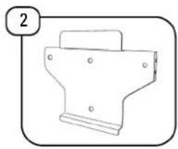
natural_image
Simple line drawing of a mechanical bracket or housing (no text or symbols)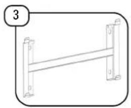
natural_image
Simple line drawing of a ladder with two vertical supports and a horizontal beam (no text or symbols)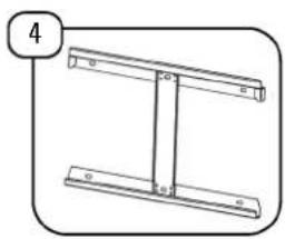
natural_image
Simple line drawing of a T-shaped metal frame with two flanges and a central vertical bar (no text or symbols)
natural_image
Two cylindrical test tubes with different internal patterns, one with a striped tip and the other with a dashed line (no text or symbols)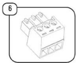
natural_image
Isometric line drawing of a mechanical component with three circular holes and triangular supports (no text or symbols)
natural_image
Illustration of a bolt and two separate bolts (no text or symbols)
natural_image
Simple line drawing of a cylindrical resistor with a shaft, enclosed in a rounded rectangular frame (no text or symbols)
natural_image
Illustration of various connectors and screws (no text or symbols)
natural_image
Simple line drawing of a handheld electronic device with a handle and connector (no text or symbols)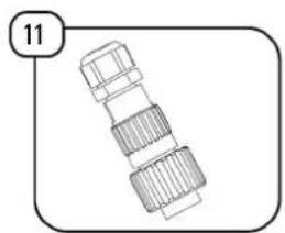
natural_image
Technical line drawing of a mechanical component with no visible text or symbols
natural_image
Simple line drawing of a mechanical component with a circular end and cylindrical body, no text or symbols present.
natural_image
Illustration of a cylindrical device with a flanged top and internal components (no text or symbols)
natural_image
Illustration of a cylindrical device with a flanged top and internal components, no text or symbols present.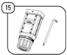
natural_image
Technical line drawing of a mechanical device with a handle and part, no visible text or symbols
natural_image
Isometric line drawing of a 3-pin electrical connector (no text or symbols)
natural_image
Simple line drawing of a tool or tool with a handle and base, enclosed in a rounded rectangle (no text or symbols)
natural_image
Simple line drawing of a pen and two small objects, no text or symbols present
text_image
19 itext_image
Sequence of house icons with checkmarks and X marks indicating weather or damage, showing a sequence from rain to heat.text_image
Technical diagram illustrating the assembly of a device with labeled parts and directional arrows indicating motion or assembly.natural_image
Technical line drawing of a heat exchanger or cooling unit with two views (top and side), no text or symbols present.natural_image
Technical line drawing of a device casing with internal components and a close-up view of its side panel (no text or symbols)natural_image
Technical line drawing of a device with labeled ports and a close-up inset showing internal components (no text or symbols present)natural_image
Technical line drawings of mechanical components (no text or symbols)natural_image
Technical line drawing of a device rear panel with internal components and a magnified inset showing internal wiring (no text or symbols)text_image
Technical diagram of a server rack with labeled components and close-up insets showing internal structure and component layout.natural_image
Exploded view diagram of a mechanical component showing internal parts and a handle (no text or symbols)natural_image
Diagram of a cylindrical connector with internal components and directional arrows indicating rotation (no text or symbols)natural_image
Line drawing of a rectangular electronic device with ports and a cable inserted (no text or symbols)text_image
ICP IGA ID PIAsnatural_image
Technical line drawing of a device with internal components and a close-up view of its internal structure (no text or symbols)8.2. TROUBLESHOOTING.
text_image
System Work Mode STA Setting AP Setting Other Setting Account Upgrade SW Restart Restore MID HF-LPT210 Software Version 7.10.31 (2021-12-08 17:00 2M) WiFi Work Mode AP/STA AP mode SSID WIFI-AP@resever1 IP Address 10.10.103.254 MAC Address 36.EA.E7.F8.C4.58 STA Mode Router SSID Signal Strength IP Address MAC Address Web Ver:1.0.14text_image
System Work Mode STA Setting AP Setting Other Setting Account Upgrade SW Restart Restore Network Name (SSD) Note: case sensitive SSD source: In-PCR Scan Encryption Method WPA2PSK Encryption Algorithm AES Password ****** Show passwords Obtain an IP address automatically Enable IP Address 173.26.12.80 Subset Mask 255.255.00 Gateway Address 173.25.25.12 DNS Server Address 173.12.16.85 Save Web Ver 1.0.14text_image
System Work Mode STA Setting AP Setting Other Setting Account Upgrade 5W Restart Restore Network Name (SSID) Node case sensitive S3D_user_istation Scam Encryption Method WPA2PSK Encryption Algorithms AES Password Those passwords Obtain an IP address automatically Enable IP Address 172.26.12.82 Subset Mask 285.285.0.0 Gateway Address 172.26.26.12 DNS Server Address 172.13.16.85 Save Web Ver:1.0.14Fig. 54. Pantalla guardar password.
text_image
System Work Mode STA Setting AP Setting Other Setting Account Upgrade SW Restart Restore Saved Successfully! Configurations will take effect after restart. After restart, you will need to re-login the configuration interface for other settings, so it is recommended to restart after completing all settings. Please click (Restart) to restart now, or click (Back) to continue setting. You can restart after all configuration. Restart Back Web Vis:1.0.14text_image
Rebooting Successful System Work Mode STA Setting AP Setting Other Setting Account Upgrade SW Restart Restore You can choose to manually close the page or reconnect the WiFi module of network and then login to the configuration interface.www.linkedin.com/company/salicru


USER MANUAL

text_image
salicru ENTHREE-PHASE SOLAR INVERTERS CONNECTED TO THE GRID
EQUINOX
EQX2 4002-T, EQX2 5002-T, EQX2 6002-T, EQX2 8002-T, EQX2 10002-T, EQX2 12002-T, EQX2 15002-T, EQX2 17002-T, EQX2 20002-T, EQX2 25002-T, EQX2 33004-T, EQX2 40004-T, EQX2 50004-T, EQX2 60004-T, EQX2 100010-T
General Index
1. INTRODUCTION
1.1. THANK-YOU LETTER
2. SAFETY INFORMATION
2.1. USING THIS MANUAL
2.2. NOTES ON SAFETY.
2.3. CONVENTIONS AND SYMBOLS
2.3.1. Explanation of the symbols.
3. QUALITY ASSURANCE AND STANDARDS
3.1. MANAGEMENT STATEMENT
3.2. STANDARDS
3.3. ENVIRONMENT
4. PRODUCT DESCRIPTION.
4.1. BASIC FEATURES.
4.1.1. Function.
4.12. Models.
4.1.3. Applicable neutral points.
4.1.4. Storage conditions.
4.2. DIAGRAMS
4.2.1. 2 MPPT units (EQX2 4002-T .. EQX2 25002-T).
4.2.2. 4 MPPT units (EQX2 33004-T, EQX2 40004-T, EQX2 50004-T and EQX2 60004-T).
4.2.3. 10 MPPT units (EQX2 100010-T).
4.3. SCREEN INTERFACE AND WIFI MODULE.
4.4. PACKING LIST.
5. INSTALLATION
5.1. LOCATION.
5.1.1. Installation location.
5.1.2. Recommended installation distances.
5.2. ASSEMBLY PROCESS.
5.2.1. 2 MPPT units (EQX2 4002-T .. EQX2 25002-T).
5.2.2. 4 MPPT units (EQX2 33004-T, EQX2 40004-T, EQX2 50004-T and EQX2 60004-T) and 10 MPPT units (EQX2 110010-T).
5.3. ELECTRIC CONNECTION.
5.3.1. External earthing connection.
5.3.2. Solar field connection.
5.3.3. Connecting the AC outlet.
5.4. INSTALLATION OF THE MONITORING DEVICE.
5.4.1. Mechanical installation.
5.5. RS485 CONNECTION.
5.5.1. Description of the terminals.
5.5.2. Wiring steps.
5.6. GENERAL INSTALLATION DIAGRAM.
6. START-UP AND SHUTDOWN.
7.1. SYSTEM FIRMWARE UPDATE.
7.2. DESCRIPTION OF THE SCREENS.
7.3. ON-LINE MONITORING OF THE INSTALLATION.
7.3.1. Download and register the "EQX-sun" app.
7.3.2. Configuration of the installation (plant) in the EQX-sun app.
7.3.3. "12h" Monitoring (Day).
7.3.4. "24h" monitoring. (Day and night).
7.3.5. Operation of the EQX-sun app.
7.3.6. Individual plant screen.
8. TROUBLESHOOTING GUIDE
8.1. ERROR MESSAGES.
8.2. TROUBLESHOOTING.
8.3. MAINTENANCE.
9. TECHNICAL FEATURES.
9.1. 2 MPPT UNITS.
9.2. 4 AND 10 MPPT UNITS.
10. ANNEX. WIFI MODULE SETUP.
1. INTRODUCTION
1.1. THANK-YOU LETTER
We would like to thank you for purchasing this product. Read this instruction manual carefully in order to familiarise yourself with its contents. You will get the most out of the unit, achieve a higher degree of satisfaction and guarantee high levels of safety the more you understand the unit.
Please do not hesitate to contact us for any further information or any questions you may have.
Yours sincerely,
SALICRU
- The unit described in this manual can cause serious physical injury if handled incorrectly. Therefore, the unit must only be installed, serviced and/or repaired by our staff or by qualified personnel.
- Although every effort has been made to guarantee that the information in this user manual is complete and accurate, we are not responsible for any errors or omissions that may be present.
The images included in this document are for illustrative purposes only and may not accurately represent the parts of the unit shown. Images are not binding and may be modified without notice. However, any differences will be reduced or resolved through the correct labelling on the unit. - In line with our policy of continuous development, we reserve the right to modify the specifications, operating principle or actions described in this document without prior notice.
- The reproduction, copying, transfer to third parties, modification or translation in full or in part of this manual or document, in any form or by any means, without prior written consent from our company, is prohibited, with us reserving the full and exclusive right of ownership to it.
2. SAFETY INFORMATION
2.1. USING THIS MANUAL
- This user manual applies to the units described on the cover and intends to be a guide that describes the installation and start-up instructions under safe conditions and in accordance with the standards. Please read the entire manual before carrying out any action, procedure or operation with the unit, especially before applying voltage to the input, respecting the actions in the order shown in this manual.
- Compliance with the "Safety instructions" is mandatory; therefore, the user will be legally responsible for observing and applying them at all times.
Compliance with the "Safety instructions" is mandatory; therefore, the user will be legally insible for observing and applying them at all times.


do not fully or partially understand theinstructions, especially those relating to safety, should not proceed to install or commission the unit, this may pose a risk to your safety or that of othere, with the possibility of causing serious injury and death , in addition to causing damage to thement and/or to loads and the installation .
- Local electrical regulations and different restrictions at the customer's location may invalidate some recommendations contained in the manuals. Where discrepancies exist, the relevant local regulations must be followed.
- All units are supplied with the corresponding labels to guarantee the correct identification of each part. In addition, the user can refer to the user manual at any time during installation or start-up operation, which provides clear, well-organised and easy-to-understand information.
- Finally, once the unit is installed and in operation, we recommend that you keep the documentation in a safe place that is easy to access, in case of any future queries that may arise.
The following terms are used interchangeably in the document to refer to:
- "EQX2-T, equipment or unit"- Equinox2 photovoltaic inverter.
• "T.S.S." - Technical Service and Support. - "Customer, installer, operator or user".- They are used interchangeably and, by extension, to refer to the installer and/or the operator who will carry out the corresponding actions, whereby the responsibility for carrying out the respective actions may be held by the same person when they act on behalf or in representation of the installer or operator.
2.2. NOTES ON SAFETY.
- Before installation, read this manual carefully and strictly follow its instructions.
- Installers must receive professional training or obtain certificates of professional qualification related to electricity.
- During installation, do not open the front cover of the inverter. In addition to carrying out work on the wiring terminal (as indicated in this manual), touching or changing components without authorisation may cause personal injury, damage to the inverters, and void the warranty.
- All electrical installations must comply with local electrical safety regulations.
- If the inverter needs maintenance, please contact the designated technical personnel for installation and maintenance.
- To use this inverter connected top the grid to generate power, permission from the local power supply authority is required.
- The temperature of some parts of the inverter may exceed 60^ C during operation. To avoid burns, do not touch the inverter during operation. Let it cool down before doing so.
- When exposed to sunlight, the solar field generates a dangerously high DC voltage. Operate in accordance with the instructions in manual, danger of death.
2.3. CONVENTIONS AND SYMBOLS
The table below shows the symbols that may appear in this manual and their definition:

Danger
Hazardous situation which, if not avoided, could result in death or serious injury to personnel.

Warning
Potentially hazardous situation which, if not avoided, could result in death or serious injury to personnel.

Caution
Potentially hazardous situation which, if not avoided, could result in minor or moderate injury to personnel.

Attention
Safety warning information about the equipment or the environment, to prevent damage to the equipment, data loss, degradation of performance or other unpredictable results.

Note
This symbol highlights important information, best practices and tips, etc.
Tab. 1. Symbols used in this manual.
2.3.1. Explanation of the symbols.
This chapter explains the symbols that appear on the inverter, label and packaging.
2.3.1.1. Symbols on the inverter.


Inverter status indicator.
Inverter operation indicator.
Earthing connection symbol, the inverter housing must be properly earthed.
Tab. 2. Inverter symbols.
2.3.1.2. Inverter label symbols.


The inverter may not be disposed of with household waste.
Please read the instructions carefully before installation.
Do not touch any internal part of the inverter for 5 minutes after it has been disconnected from the grid and from the photovoltaic input.
CE marking, the inverter meets the requirements of the applicable CE directives.
SGS certification.


Danger. Risk of electric shock.
Do not touch. Hot surface during operation.
Danger of electric shock, live parts, risk of electric shock, do not touch.
Tab. 3. Labelling symbols.
2.3.1.3. Packaging symbols.


Handle with care.
Indicator of the correct direction of the packaging.
Earthing connection symbol, the inverter housing must be properly earthed.
Stacked layers 6.
3. QUALITY ASSURANCE AND STANDARDS
3.1. MANAGEMENT STATEMENT
Our aim is to satisfy our customers. Management has established a Quality and Environmental Policy for such purposes. As a result, a Quality and Environmental Management System will be implemented, which will ensure that we are compliant with the requirements of the ISO 9001 and ISO 14001 standards and that we meet all customer and stakeholder requirements.
The company management is also committed to the development and improvement of the Quality and Environmental Management System, through:
- Communication to the entire company of the importance of meeting both the customer's requirements, and legal and regulatory requirements.
- Dissemination of the Quality and Environmental Policy and setting of the Quality and Environment targets.
- Management reviews.
•Provision of the necessary resources.
3.2. STANDARDS
The product is designed, manufactured and marketed in accordance with the ISO 9001 Quality Assurance standard. The C€ mark indicates conformity with the EEC Directives through application of the following standards:
• 2014/35/EU. - Low voltage directive.
• 2014/30/EU directive - Electromagnetic compatibility -CEM-.
- 2011/65/EU. - Restriction of hazardous substances in electrical and electronic equipment (RoHS).
• 2012/19/EU. - Waste electrical and electronic equipment (WEEE).
Grid connection laws in Spain:
- Royal Decree RD647/2020, which regulates aspects necessary for the implementation of the grid connection codes of certain electrical installations.
- Royal Decree RD244/2019, which regulates the administrative, technical and economic conditions of self-consumption of electrical energy
According to the specifications of the corresponding harmonised standards. Reference standards:
Electrical safety:
- IEC/EN/UNE 62109-1:2010. Safety of power converters for use in photovoltaic power systems. Part 1: General requirements.
- IEC/EN/UNE 62109-2:2011. Safety of power converters for use in photovoltaic power systems. Part 2: Particular requirements for inverters.
Electromagnetic compatibility:
- IEC/EN/UNE 61000-6-2:2005. Electromagnetic compatibility (EMC). Part 6-2: Generic standards. Immunity in industrial environments.
- IEC/EN/UNE 61000-6-3:2007/A1:2011. Electromagnetic compatibility (EMC). Part 6-3: Generic standards. Emission standard for residential, commercial and light-industrial environments.
Efficiency:
- IEC/EN/UNE 61683:1999. Photovoltaic systems. Power conditioners. Procedure for measuring efficiency.
Environment:
- IEC/EN/UNE 60068-2-1:2007 / IEC/EN/UNE 60068-2:2007 / IEC/EN/UNE 60068-14:2009 / IEC/EN/UNE 60068-30:2005 Environmental tests. Cold/Dry heat/Temperature changes/Cyclic heat.
Grid connection:
- IEC/EN/UNE 62116:2014. Utility-interconnected photovoltaic inverters. Test procedure of islanding prevention measures.
- IEC 61727:2004. Photovoltaic (PV) systems - Characteristics of the utility interface.
- (EU) 2016/631 Commission Regulation of 14 April 2016 establishing a network code on requirements for grid connection of generators.
Only for installations in Spain :
- UNE 217002:2020. Inverters for connection to the distribution network. Testing of requirements for DC grid injection, overvoltage generation and island operation detection system.
- UNE 217001:2020. Tests for systems intended to avoid the energy transmission to the distribution network.
- NTS631. Technical note on compliance supervision for electricity generation modules according to regulation (EU) 2016/631.

The manufacturer shall not be held responsible for any damage caused by the user altering or tampering with the unit in any way.

The EC declaration of conformity for the product is available for the customer and can be requested from our head office.
3.3. ENVIRONMENT
This product has been designed with the protection of the environment in mind and has been manufactured in accordance with the ISO 14001 standard.
Recycling the unit at the end of its useful life:
Our company commits to using the services of approved companies that comply with the regulations in order to process the recovered product at the end of its useful life (please contact your distributor).
Packaging:
To recycle the packaging, follow the applicable legal regulations, depending on the particular standards of the country where the unit is installed.
4. PRODUCT DESCRIPTION.
4.1. BASIC FEATURES.
4.1.1. Function.
The inverter of the EQX2-T series is a three-phase grid-connected photovoltaic inverter used to efficiently convert the DC power generated by the photovoltaic string into AC power, so it can be injected into the grid.
4.1.2. Models.
The EQX2-T series of three-phase inverters has the following models:
- EQX2 4002-T
- EQX2 20002-T
- EQX2 5002-T
- EQX2 25002-T
•EQX2 6002-T •EQX2 33004-T - EQX2 8002-T
- EQX2 40004-T
- EQX2 10002-T
- EQX2 50004-T
- EQX2 12002-T
- EQX2 60004-T
- EQX2 15002-T
- EQX2 100010-T
•EQX2 17002-T
4.1.3. Applicable neutral points.
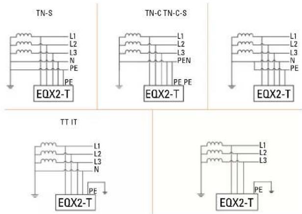
The applicable neutral points for the models of the EQX2-T series are TN-S, TN-C, TN-C-S, TT and IT. When applied to a TT grid, the voltage from N to PE should be less than 30 V. For more details, refer to Fig. 1:
text_image
TN-S L1 L2 L3 N PE PF EQX2-T TN-C TN-C-S L1 L2 L3 PEN PE PE EQX2-T L1 L2 L3 N PE EQX2-T TT IT L1 L2 L3 N PE EQX2-T L1 L2 L3 PE EQX2-TFig. 1. Applicable neutral points.
4.1.4. Storage conditions.
• The inverter must be stored in its original packaging.
- The temperature and humidity should be between -30°C and +60°C, and less than 90%, respectively.
- If it is necessary to stack a group of inverters, the height of each stack should not exceed 6 levels.
4.2. DIAGRAMS
4.2.1. 2 MPPT units (EQX2 4002-T .. EQX2 25002-T).
text_image
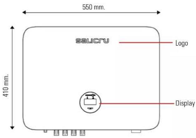
550 mm. saicru Logo 410 mm. DisplayFig. 2. Front view.
text_image
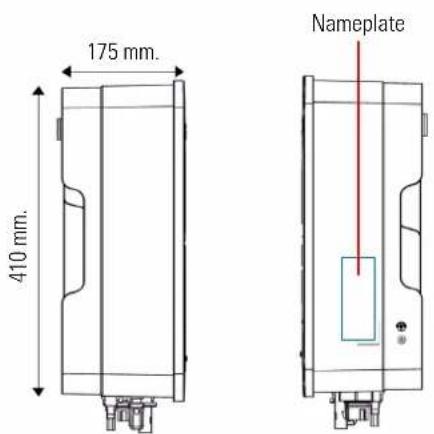
175 mm. 410 mm. NameplateFig. 3. Side view.

text_image
175 mm. ① ④ ② ③ ⑤ ⑤Fig. 4. Bottom view.
text_image
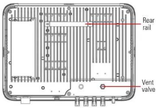
Rear rail Vent valveFig. 5. Rear view.
4.2.2. 4 MPPT units (EQX2 33004-T, EQX2 40004-T, EQX2 50004-T and EQX2 60004-T).

text_image
600 mm salicru Logo 400 mm DisplayFig. 6. Front view.
text_image
270 mm 400 mm
text_image
NameplateFig. 7. Side view.
text_image
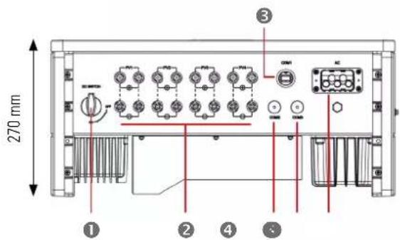
270 mm ① ② ③ ④Fig. 8. Bottom view.
text_image
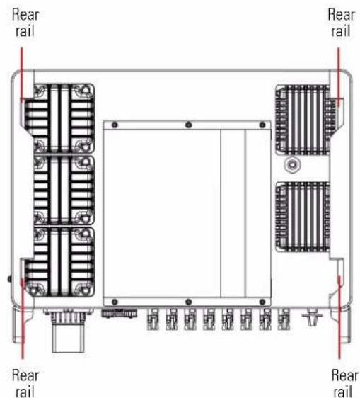
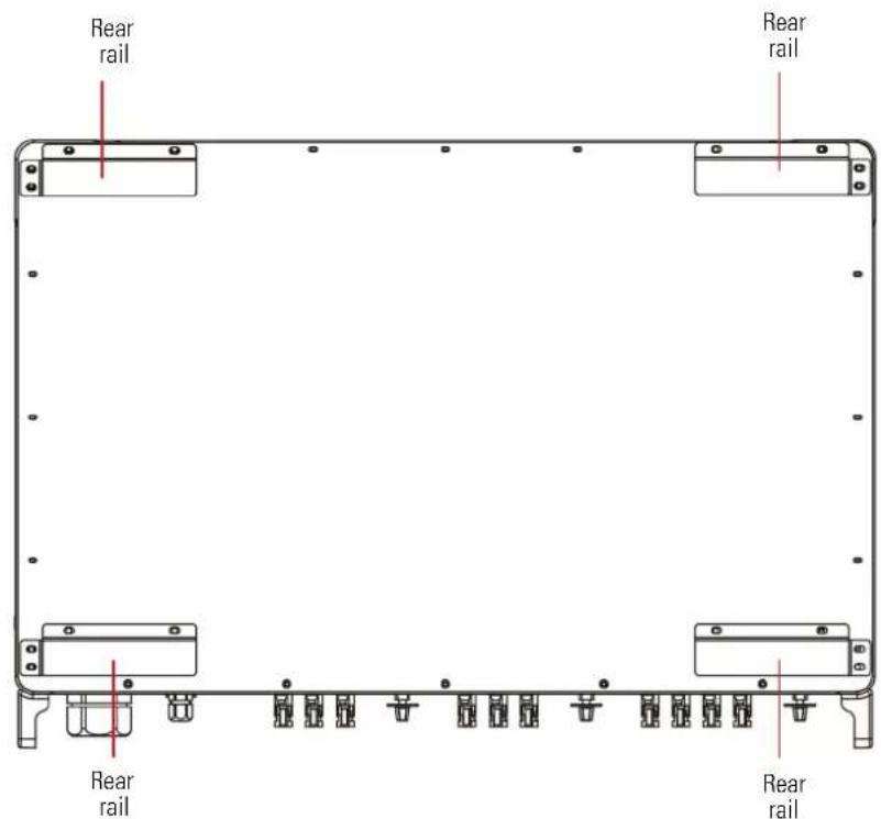
Rear rail Rear rail Rear rail Rear railFig. 9. Rear view.
4.2.3. 10 MPPT units (EQX2 100010-T).
text_image
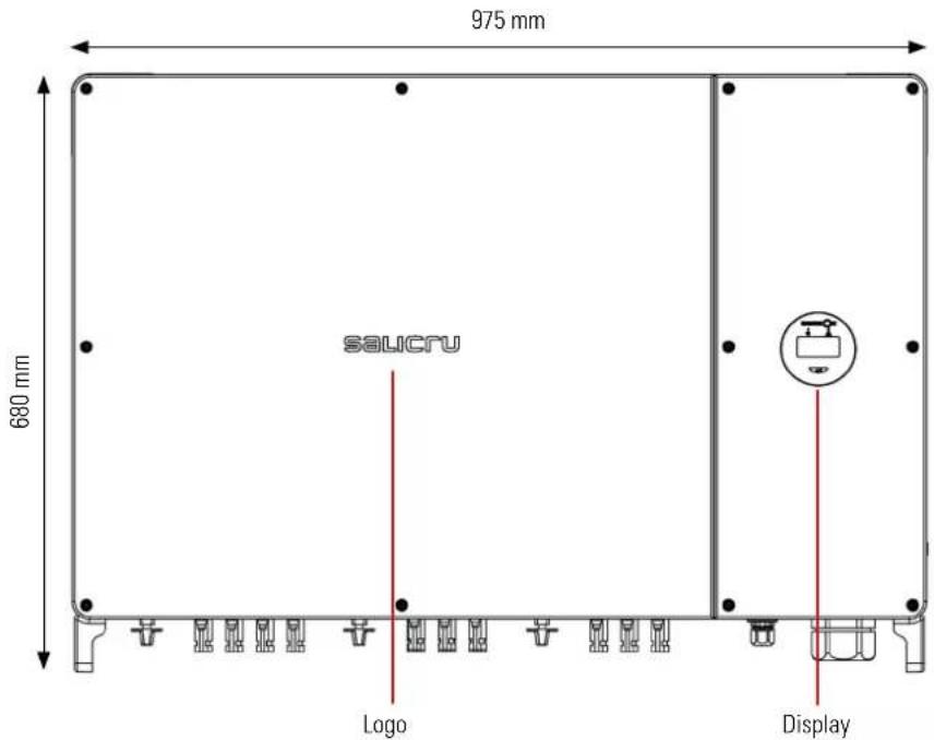
975 mm 680 mm salicru Logo DisplayFig. 10. Front view.

text_image
290 mm 680 mm NameplateFig. 11. Side view.
text_image
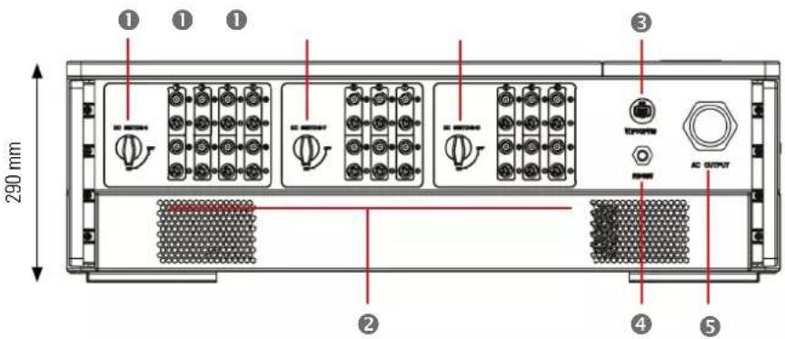
290 mm ① ① ① ② ③ AC OUTPUT ④ ⑤Fig. 12. Bottom view.
text_image
Rear rail Rear rail Rear rail Rear railFig. 13. Rear view.
The connection terminals are located at the bottom of the unit, as shown in the following table:
| Item | Terminal Note | |
| 1 | DC switch On/Off switch | |
| 2 | DC input terminal PV | Connector |
| 3 | COM1 port WiFi/IAN/GPRS/4G connector | |
| 4 | COM2/COM3 port CT/RS485/DRED connector | |
| 5 | AC output terminal Connection for AC output | |
Tab. 4. Connection terminals.
4.3. SCREEN INTERFACE AND WIFI MODULE.

text_image
EQUINOX ① ② ③ ④Fig. 14. Synoptic chart view.

natural_image
Line drawing of a mechanical device with a handle and labeled component (no text or symbols)Fig. 15. Wi-Fi module view.
| Indicator Item Status Description Solution | ||||
| On indicator | 1 | Off No voltage detection or input voltage too low. | ||
| Slow flash Inverter On, waiting for grid connection. | ||||
| Fast flash Grid detected. Self-test mode. | ||||
| On Normal connected to the grid and generating energy. | ||||
| OLED display | 3 | On Displays inverter operation information. | ||
| Off | If there is no response when pressing the button, the screen is faulty or not connected properly. | |||
| Button | 4 | (Physical) | Change the information on the OLED screen and set the parameters with a short press and long press. | |
| Alarm indicator | 2 | On | The communication between the inverter and the server is normal. However, the inverter reports an error. | Check the guide for more information about common faults and troubleshooting. |
| 5 | ||||
| 2 | Off | The WiFi module is not properly connected to the inverter's "Com" port. The WiFi module is restored. | Check if the WiFi module is connected properly to the inverter. Remove and insert the Smart Dongle; Restart the inverter. | |
| 5 | Changed router or password. The WiFi signal is too weak at the place of installation. | Remove and insert the Smart Dongle; configure the WiFi module, move the router closer to the inverter. Register the user account. | ||
| 2 | Slow flash | The WiFi module is not connected to the router. | 1. Remove and insert the WiFi module. 2. Reload WIFI3. Configure the WiFi module again. | |
| 5 | Off | |||
| 2 | Fast flash | The WiFi module connects to the router, but not to the server | Check that the router has an Internet connection. Check that the firewall is not blocking port 5743. | |
| 5 | On | |||
| 2 | Off | Communication between inverter and server is normal. Communication is normal. | ||
| 5 | On | |||
Tab. 5. Synoptic chart elements and WiFi module.
4.4. PACKING LIST.
The packaged inverter includes the following accessories. Check that all of the accessories supplied with the inverter are included when you receive the package. Refer to the packing list in Tab. 6.
natural_image
Line drawing of a portable electronic device with control buttons and a top panel (no text or symbols)
natural_image
Simple line drawing of a mechanical bracket or housing with mounting holes (no text or symbols)
natural_image
Simple line drawing of a ladder with two vertical supports and a horizontal beam (no text or symbols)
natural_image
Simple line drawing of a structural frame with two vertical members and a central horizontal bar (no text or symbols)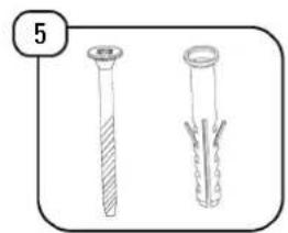
natural_image
Two cylindrical test tubes with different internal patterns, one with a cap and the other with internal cracks (no text or symbols)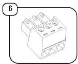
natural_image
Isometric line drawing of a mechanical component with three circular holes and triangular supports (no text or symbols)
natural_image
Illustration of a bolt and two separate bolts (no text or symbols)
natural_image
Simple line drawing of a cylindrical resistor with a pin, enclosed in a rounded rectangular border (no text or symbols)
natural_image
Illustration of four different types of screwdrivers (no text or symbols)
natural_image
Simple line drawing of a mechanical component with a handle and base, no text or symbols present
natural_image
Technical line drawing of a mechanical component with no visible text or symbols
natural_image
Simple line drawing of a mechanical component with a circular end and cylindrical body, enclosed in a rounded rectangular border (no text or symbols)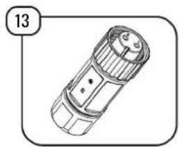
natural_image
Line drawing of a cylindrical device with a circular top and internal structure, no text or symbols present.
natural_image
Technical line drawing of a flashlight with no visible text or symbols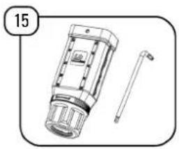
natural_image
Technical line drawing of a mechanical device with a cylindrical pin and a numbered label (15), no readable text or symbols present.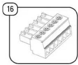
natural_image
Technical line drawing of a 3D connector with multiple pins (no text or symbols)
natural_image
Simple line drawing of a tool with a handle and base, no text or symbols present
natural_image
Simple line drawing of a mechanical device with two components and a numbered label '18' (no text or symbols on the device itself)
text_image
19 iFig. 16. Items included in the packaging.
| Item Description | 2 MPPTs | 4 MPPTs | 10 MPPTs | |
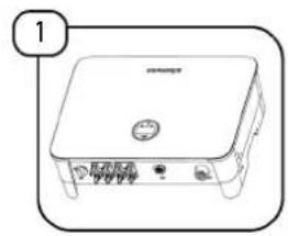
| 1 Inverter 1 1 1 | ||||
| 2 Wall mounting bracket 1 0 0 | ||||
| 3 Wall mounting bracket 0 1 0 | ||||
| 4 Wall mounting bracket 0 0 1 | ||||
| 5 Screws and plugs 4 0 0 | ||||
| 6 3-pin connector 2 0 0 | ||||
| 7 Support screw 0 4 6 | ||||
| 8 Terminal resistance 120 Ω 0 1 0 | ||||
| 9 Terminal pairs PV (+ and −) | 2^[1],3^[2] or 4^[3] | 8 20 | ||
| 10 | WiFi module | 1 | 1 | 1 |
| 11 | AC terminal | 1 | 0 | 0 |
| 12 | Earthing terminal | 1 | 0 | 0 |
| 13 | Meter communication terminal | 0 | 1 | 0 |
| 14 | RS485 communication terminal | 0 | 1 | 0 |
| 15 | AC terminal | 0 | 1 | 0 |
| 16 | 6-pin terminal | 1 | 0 | 1 |
| 17 | Ring spanner | 0 | 0 | 1 |
| 18 | L-shaped plate | 1 | 0 | 0 |
| 19 | User manual | 1 | 1 | 1 |
^11 4 to 12 kW units
^12 15 kW units
17 to 25 kW units

2 MPPT units: EQX2 4002-T, EQX2 5002-T, EQX2 6002-T, EQX2 8002-T,
FOX2 10002-T, FOX2 12002-T, FOX2 15002-T, FOX2 17002-T, FOX2 20002-T
and EQX2 25002-T.
4 MPPT units: EOX2 33004-T, EOX2 40004-T, EOX2 50004-T and EOX2 60004-T.
10 MPPT units: EQX2 100010-T.
Tab. 6. Packing list.
5. INSTALLATION
5.1. LOCATION.
The inverters of the EQX2 series have been designed with an enclosure with IP65 degree of protection, suitable for indoor and outdoor installations. The following factors should be taken into account when selecting an installation location for the inverter:
- The wall on which the inverters are mounted must be able to support the weight of the inverter.
- The inverter must be installed in a well-ventilated environment.
- Make sure that the inverter is not exposed directly to strong sunlight to avoid operation at excessive temperatures. The inverter should be installed in a place sheltered from direct sunlight and rain.
- Install the inverter at eye level for easy reading of the data on the screen and better maintenance.
- The ambient temperature of the place where the inverter is installed must be between -30°C and +60°C.
- The surface temperature of the inverter can reach up to 75^ C. To avoid the risk of burns, do not touch the inverter during operation and install it out of the reach of children.
5.1.1. Installation location.

We recommend installing inverters indoors. However, if there is no choice but to install outdoors, in Fig. 17 shows
recommended locations, as well as those to avoid:


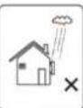
Fig. 17. Recommended locations for the inverter.

Do not store flammable and/or explosive materials near the inverter.
5.1.2. Recommended installation distances.
Installation angle and spacing: Check that the inverter is installed on a vertical surface and that it keeps the following minimum safety distances with respect to other elements for optimal ventilation, as shown in Fig. 18:

text_image
90° A B SSUCFU B A 180°Fig. 18. Recommended installation distances.
| A | B | |
| EQX2 4002-T..EQX2 25002-T | 500 | 300 |
| EQX2 33004-T, EQX2 40004-T, EQX2 50004-T, EQX2 60004-T | 800 | |
| EQX2 100010-T 1000 |
5.2. ASSEMBLY PROCESS.
Steps:
5.2.1. 2 MPPT units (EQX2 4002-T .. EQX2 25002-T).
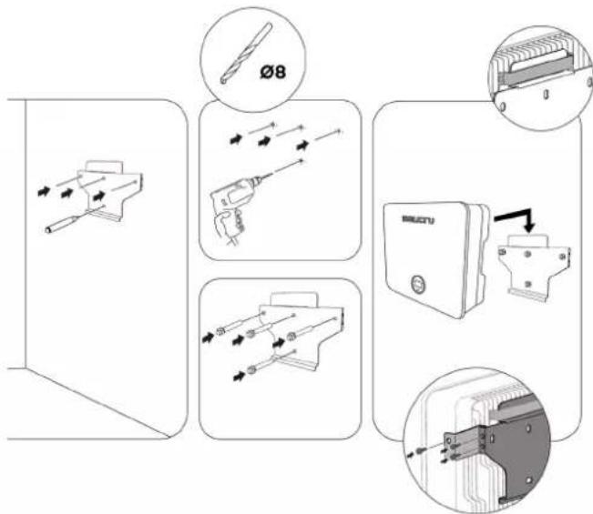
text_image
Technical diagram illustrating the assembly of a device with labeled parts including tool, screwdriver, and circuit board components.5.2.2. 4 MPPT units (EQX2 33004-T, EQX2 40004-T, EQX2 50004-T and EQX2 60004-T) and 10 MPPT units (EQX2 110010-T).

text_image
Φ 12 mmFor 4 MPPT units:

text_image
Handle HandleFor 10 MPPT units:

text_image
Handle Handle5.3. ELECTRIC CONNECTION.

Danger
An excessively high voltage on the conductive part of the inverter may cause electric shock. When installing the inverter, make sure that the AC and DC sides of the re completely de-energised.

Warning
Do not connect the positive or negative poles of the photovoltaic panel to earth, since this may cause major damage to the inverter.

Warning
Static electricity can damage the inverter's electronic components. Take the necessary anti-static measures during installation and maintenance.

Attention
Do not use terminals of different manufacturers or of different types, other than those included in the accessory pack. SALICRU shall not be held liable for any image caused by the use of unauthorised terminals.

Attention
Moisture and dust can damage the inverter; check that the cable gland is tight enough during installation. The warranty will be void if the inverter is damaged as an improperly installed cable gland.
5.3.1. External earthing connection.

Danger
Do not connect the neutral N wire as a protective earthing wire to the inverter housing. This may cause electric shock.

Attention
An optimal earthing connection can withstand resist surge discharges and improve EMI performance. Inverters must be properly earthed.
For systems with a single inverter, the PE wire must be earthed.
For a multi-inverter system, all PE cables from the inverters must be connected to the same copper earthing bar to ensure equipotential bonding.
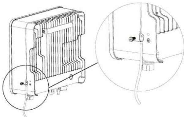
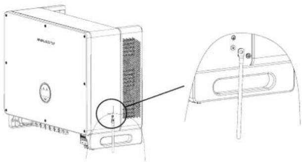
Steps for connecting the terminal to earth:
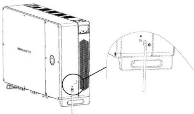
- The external earthing connection terminal is located on the lower right side of the inverter.
- Fasten the earthing connection terminal to the PE cable with a suitable tool and lock the earthing connection terminal to the earthing connection hole on the bottom right side of the inverter as shown in Fig. 19, Fig. 20, Fig. 21.
- The cross-sectional area of the external earthing wire is 4 mm ^2 .
5.3.1.1. 2 MPPT units (EOX2 4002-T .. EQX2 25002-T).
natural_image
Technical line drawing of a heat exchanger or cooling unit with internal circuitry and wiring details (no text or symbols)Fig. 19. Earthing terminal connection.
5.3.1.2. 4 MPPT units (EQX2 33004-T, EQX2 40004-T, EQX2 50004-T and EQX2 60004-T).
natural_image
Technical line drawing of a device housing with a close-up view showing internal components and mounting bracket (no text or symbols)Fig. 20. Earthing terminal connection.
5.3.1.3. 10 MPPT units (EQX2 110010-T).
natural_image
Technical line drawing of a server unit with labeled components and an inset view showing internal components (no text or symbols present)Fig. 21. Earthing terminal connection.
5.3.2. Solar field connection.
- The following must be taken into account when making the electrical connections to the inverter:
a. Disconnect the AC switch on the grid side.
b. The inverter's DC switch must be set to "OFF".
c. To ensure that the best practices are followed, check that the photovoltaic panels connected in each string are of the same model and specifications.
d. Check that the maximum output voltage of each photovoltaic string does not exceed the maximum voltage specified in the table of technical characteristics in the section "9. Technical features."
e. Insert the relevant DC circuit breakers, according to the following Tab. 7:
f. A distance of 5 m must be left between the circuit breakers and the unit.
| Model | Isolating switch | Fuses | Overvoltage circuit breaker | |
| If no lightning rod is installed | If lightning rods are installed or there is a high probability of lightning | |||
| EQX2 4002-TEQX2 5002-TEQX2 6002-TEQX2 8002-TEQX2 10002-TEQX2 12002-TEQX2 15002-TEQX2 17002-TEQX2 20002-TEQX2 25002-T | Built into the unit | 1000 Vdc15 Afuses | Type II40 kA600 Vdc | Type I+II5 kA1000 Vdc |
| EQX2 33004-TEQX2 40004-TEQX2 50004-TEQX2 60004-T | 1000 Vdc15 Afuses,1 per string | |||
| EQX2 100010-T | ||||
Tab. 7. DC circuit breakers.
- DC connector assembly procedure.
a. Select the suitable photovoltaic cable:
| Type of cable Cross-section area | ||
| General photovoltaic cable | Range (mm2) | Recommended value (mm2) |
| 2,5 - 4,0 | 4,0 | |
Tab. 8. Selecting the photovoltaic cable.
b. Strip 7 mm of the insulation sleeve of the DC cable, as shown in Fig. 22:
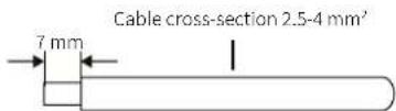
Fig. 22. Wire end stripping.
c. Remove the connector from the accessory bag, as shown in Fig. 23:

natural_image
Technical line drawings of mechanical components (no text or symbols)Fig. 23. Disassembling the connector.
d. Insert the DC cable through the DC connector nut on the metal terminal and press the terminal with professional crimping pliers (pull the cable to check if the terminal is well connected to the cable), as shown in Fig. 24:

text_image
To ensure an optimal connection, use an approved tool to crimp the terminals.Fig. 24. Crimping the cable.
e. Insert the positive and negative cables into the corresponding positive and negative connectors, pull the DC cable to make sure that the terminal is well connected to the connector.
f. Use an open-end wrench to screw the nut all the way in and make sure that the terminal is sealed well, as shown in Fig. 25:
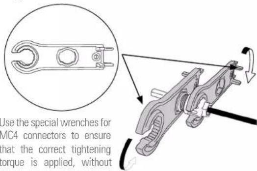
text_image
Use the special wrenches for MC4 connectors to ensure that the correct tightening torque is applied, withoutFig. 25. Using an open-end wrench.

Before assembling the DC connector, make sure that the cable has the correct polarity.


Use a multimeter to measure the DC input string voltage, check the polarity of the DC input cable, and make sure that the voltage of each string is within the 600 V range.
See the "Input" section in Tab. 15.
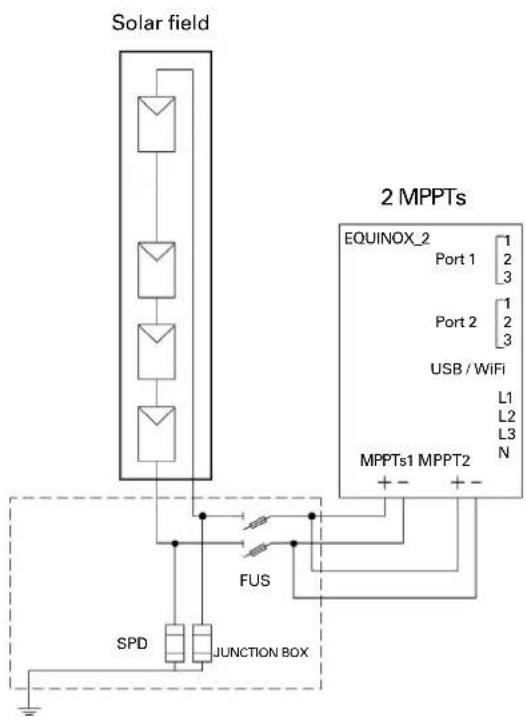
- Connect the cables to the inverter as shown in the following connection diagrams:

for installations with a single solar field (panels in the same direction and strings of equal length):

Solar panels that make up a string must have the same technical characteristics.
Connect the strings to each of the unit's inputs, taking into account the input limits specified in the section "9. Technical features." The following diagram is a connection example for a 4 to 12 kW unit:

flowchart
graph TD
    A["Solar field A"] --> B["2 MPPTs"]
    C["Solar field B"] --> B
    B --> D["EQUINOX_2 Port 1: 1, 2, 3"]
    B --> E["USB / WiFi: 1, 2, 3"]
    B --> F["MPP Ts1 MPPT2: L1, L2, L3, N"]
    B --> G["FUS"]
    G --> H["SPD"]
    G --> I["JUNCTION BOX"]
    H --> J["Ground"]
    I --> J
    style A fill:#f9f,stroke:#333
    style C fill:#f9f,stroke:#333
    style B fill:#ccf,stroke:#333
    style D fill:#cfc,stroke:#333
    style E fill:#cfc,stroke:#333
    style F fill:#fcc,stroke:#333
    style G fill:#cff,stroke:#333
    style H fill:#ffc,stroke:#333
    style I fill:#ffc,stroke:#333
Fig. 26. Single solar field connection, 2 strings and 2 MPPTs.

In Fig. 28 shows the connection for a 4 to 12 kW unit in case it is necessary to connect a string whose exceed the maximum intensity permitted per string.
flowchart
graph TD
    A["Solar field"] --> B["Port 1"]
    A --> C["Port 2"]
    A --> D["USB / WiFi"]
    A --> E["MPPTs1 MPPT2"]
    B --> F["FUS"]
    C --> G["SPD"]
    D --> H["JUNCTION BOX"]
    E --> I["+ - + -"]
    J["EQUINOX_2"] --> K["Port 1: 1, 2, 3"]
    J --> L["Port 2: 1, 2, 3"]
    J --> M["USB / WiFi: L1, L2, L3, N"]
Fig. 27. Single solar field connection, 1 string and 2 MPPTs.
It is recommended to choose the solar panels that are suitable for each inverter, not exceeding the maximum values specified in the section "9. Technical features."
b.
Connection for installations with solar fields of different power ratings (panels with different direction and/or strings of different lengths):
If the installation does not have the solar panels on the same plane, i.e., they receive different levels of irradiance, either due to the shape of the roof or due to the different inclination levels, or the lengths of the strings are not the same, the connection must be made as follows:

flowchart
graph TD
    A["Solar field A"] --> B["Switch"]
    C["Solar field B"] --> D["Switch"]
    B --> E["USB / WiFi"]
    D --> E
    E --> F["MPPTs1 MPPT2"]
    F --> G["+ - + -"]
    H["SPD"] --> I["FUS JUNCTION BOX"]
    I --> J["Ground"]
    style A fill:#f9f,stroke:#333
    style C fill:#f9f,stroke:#333
    style H fill:#ccf,stroke:#333
    style F fill:#cff,stroke:#333
    style G fill:#ffc,stroke:#333
    style I fill:#cfc,stroke:#333
    style J fill:#fcc,stroke:#333
Fig. 28. Connection of several solar fields and 2 MPPTs.
The diagram above is a connection example for a 4 to 12 kW unit with an input for each MPPT.
In the case of a unit that has two inputs for each MPPT, (17 to 100 kW units), connect identical strings to both inputs as indicated in the Fig. below:
flowchart
graph TD
    subgraph Solar Field A
        A1[" "] --> A2[" "]
        A3[" "] --> A4[" "]
        A5[" "] --> A6[" "]
        A7[" "] --> A8[" "]
        A9[" "] --> A10[" "]
    end

    subgraph Solar Field B
        B1[" "] --> B2[" "]
        B3[" "] --> B4[" "]
        B5[" "] --> B6[" "]
        B7[" "] --> B8[" "]
        B9[" "] --> B10[" "]
    end

    subgraph Solar Field C
        C1[" "] --> C2[" "]
        C3[" "] --> C4[" "]
        C5[" "] --> C6[" "]
        C7[" "] --> C8[" "]
        C9[" "] --> C10[" "]
    end

    subgraph Solar Field D
        D1[" "] --> D2[" "]
        D3[" "] --> D4[" "]
        D5[" "] --> D6[" "]
        D7[" "] --> D8[" "]
    end

    EQUINOX_2
    Port 1
    Port 2
    USB/WiFi
    L1
    L2
    L3
    N

    FUS
    SPD
    JUNCTION BOX
    4 MPPTs
    EQUINOX_2
    Port 1
    Port 2
    USB/WiFi
    L1
    L2
    L3
    N
Fig. 29. Connection of several solar fields and 4 MPPTs.
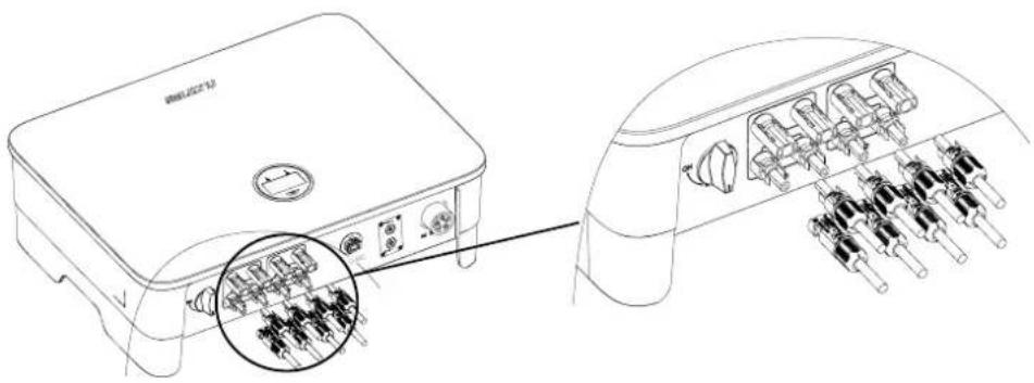
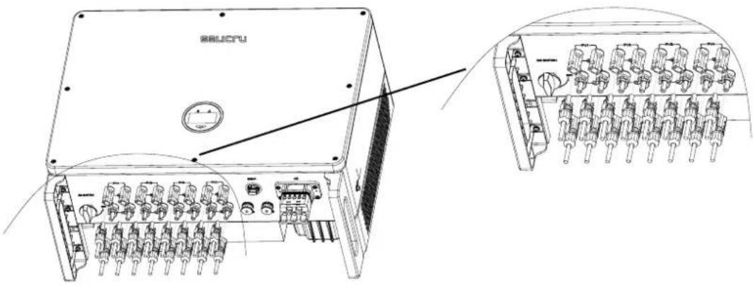
- Insert the positive and negative connectors into the respective DC input terminals of the inverter. If the terminals are properly connected, they will make a clicking sound, as shown in Fig. 30, Fig. 31 and Fig. 32:
text_image
Technical diagram of a device rear panel with labeled ports and internal components, including a magnified inset showing internal connectors.Fig. 30. Connecting the DC input terminals of units with 2 MPPTs.
text_image
BSAUCPUFig. 31. Connecting the DC input terminals of units with 4 MPPTs.

text_image
Technical diagram of a server rack with labeled components and close-up insets showing internal structure and connections.Fig. 32. Units with 10 MPPTs.

- Disconnect the AC circuit breaker from the grid side before connecting the DC input terminals.
- The DC circuit breaker must be "OFF".
- Insulate the unused DC terminals with covers.
5.3.3. Connecting the AC outlet.
Before connecting to the grid, make sure that the voltage and frequency of the grid meet the inverter's requirements. Please refer to the technical parameters for more details.
This inverter includes a built-in residual current device (RCD).
If an external residual current device (RCD) is used, a type A device must be used, with a trip current of 30 mA or more.
The recommended AC cord and switch for the EQX2 series three-phase inverter is shown in Tab. 9:
| Model Cable (mm) | ^2) |
| EQX2 4002-T | 2,5EQX2 5002-T |
| EQX2 6002-T | |
| EQX2 8002-T | 4EQX2 10002-T |
| EQX2 12002-T | |
| EQX2 15002-T 6 | |
| EQX2 17002-T | 8EQX2 20002-T |
| EQX2 25002-T | |
| EQX2 33004-T 25 | |
| EQX2 40004-T | 35EQX2 50004-T |
| EQX2 60004-T | |
| EQX2 100010-T 50 |
Tab. 9. Cable cross-sections, by model.
- Steps for connecting the AC connector.
a. Remove the AC connector from the accessory bag.
b. The fully disassembled AC connector is shown below:

AC terminal head
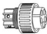
Cable gland Threaded sleeve
Fig. 33. AC connector.
c. According to the above table, select a suitable cable, remove the insulation sleeve from the AC cable about 50 mm, and remove the insulation from the end of the L/PE/N cables about 8 mm, as shown in Fig. 34:
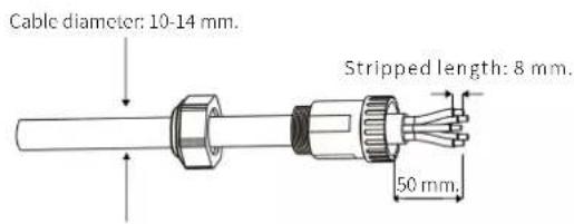
text_image
Cable diameter: 10-14 mm. Stripped length: 8 mm. 50 mm.Fig. 34. Cable stripping.
d. Insert the stripped end of the three cables into the corresponding hole of the terminal head (yellow-green cable into the PE port, phase into the L port and neutral into the N port). Pull from the cable to check that it is properly connected, as shown in Fig. 35:

natural_image
Technical line drawing of a mechanical component with no visible text or symbolsFig. 35. Inserting the bare wire into the terminal.
e. According to the direction of the arrow, push the threaded sleeve until it connects to the AC terminal head, and then turn the cable gland clockwise to lock it, as shown in Fig. 36:
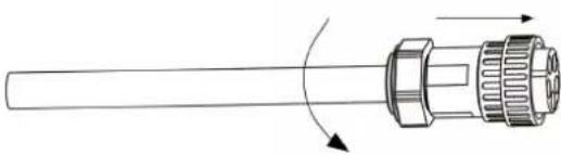
natural_image
Diagram of a cylindrical connector with internal components and directional arrows indicating rotation (no text or symbols)Fig. 36. Connecting and fastening the sleeve on the AC terminal.
f. Connect the AC connector to the inverter's AC terminal; a click indicates that the connection is in place, as shown in Fig. 37:

natural_image
Line drawing of a rectangular electronic device with ports and a cable inserted (no text or symbols)Fig. 37. Connecting the AC connector to the inverter's AC terminal.
g. Insert the relevant AC circuit breakers in between, as shown in the table below:
| Model | Circuit breaker (A) | Differential | Over-voltage protection | Previous fuse.Max. value (1/phase) |
| EQX2 4002-T | 10 | 4p 25A30mAClass A | Tipo II40kA 400VTNC | 125A gL |
| EQX2 5002-T | ||||
| EQX2 6002-T | 16 | |||
| EQX2 8002-T | ||||
| EQX2 10002-T 20 | 4p 32A30mAClass A | |||
| EQX2 12002-T | 25 | |||
| EQX2 15002-T | 30 | |||
| EQX2 17002-T | 40 | 4p 40A30mAClass A | ||
| EQX2 20002-T | ||||
| EQX2 25002-T | 50 | 4p 50A30mAClass A | ||
| EQX2 33004-T | 63 | 4p 63A30mAClass A | ||
| EQX2 40004-T | 80 | 4p 80A30mAClass A | ||
| EQX2 50004-TEQX2 60004-T | 100 | 4p 100A30mAClass A | ||
| EQX2 100010-T | 200 | 4p 160A30mAClass A |
Tab. 10. AC protections., by model.
h. Connect the other end of the hose to the AC circuit breaker in the junction box, downstream of the connection's IGA.
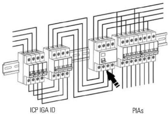
text_image
ICP IGA ID PIAsFig. 38. Electrical wiring diagram.
5.4. INSTALLATION OF THE MONITORING DEVICE.
5.4.1. Mechanical installation.
The single-phase inverter of the EQX2 series supports WiFi and RS485 communications.
Plug the WiFi module into the USB (WiFi) port located at the bottom of the inverter (as shown in Fig. 39). A "click" indicates that the module has been fitted correctly.
text_image
COM COMFig. 39. Communication device connection (WiFi antenna).
5.5. RS485 CONNECTION.
5.5.1. Description of the terminals.
The inverter's communication ports are located at the bottom and behind the COM2 board, and include the CT port, RS485 port (used for the data logger connection), as shown in Fig. 40:
text_image
Port 1 Port 2 1 1 2 2 3 3 Port 3 1 2 3 4 5 6Fig. 40. Communication ports.

| Port 1 Port 2 Port 3 | |
| STM port RS485 port Not used |
| Port No. | Function | Selector no. | Definition |
| 1 | Connect the optional STM device for the Zero Injection and Monitoring function of the EQX2 series inverters. | 1 Connect the RS 485 A cable | |
| 2 Connect the RS 485 B cable | |||
| 3 Zero | |||
| 2 | Monitoring / RS485 | 1 RS 485 A | |
| 2 RS 485 B | |||
| 3 PE / Zero | |||
Tab. 11. Communication ports.
5.5.2. Wiring steps.
- Remove the protective plate on the bottom of the inverter using a Phillips screwdriver.
- Pass the wire through the hole and connect it to the terminal in the following order: screw cap, sealing ring, insulator, metal plate, nut and 3/6 pin connector, as shown in Fig. 41:
text_image
Insulation ring Nut Screw cap Sealing ring Metal plate Port 1 2/3 Port 2 2/3 3-pin connector 20-25 mm 6 mm 20-25 mm 6 mmFig. 41. Terminal connection process.
-
Insert the cable into the port using the 3-pin connector and fasten it with a screwdriver.
-
Insert the 3-pin connector into the inverter and screw the cover plate back on using a Phillips screwdriver, as shown in Fig. 42:
natural_image
Technical line drawing of a device with internal components and an inset view showing a close-up of the internal structure (no text or symbols)Fig. 42. Connection of the 3-pin connector on the inverter.
5.6. GENERAL INSTALLATION DIAGRAM.

flowchart
graph TD
    A["Distribution network"] --> B["Kwh"]
    B --> C["Connection point / Meter"]
    D["Inverter installation"] --> E["ECUINOX_2 Port 1-3"]
    D --> F["USB / WiFi L1-L3 N"]
    D --> G["AC Protections"]
    H["CGMP (General Control and Protection Panel) Example of an existing installation"] --> I["ICP"]
    H --> J["IGA"]
    H --> K["IDs"]
    H --> L["PIAs"]
    H --> M["Loads"]
    style A fill:#f9f,stroke:#333
    style D fill:#ccf,stroke:#333
    style H fill:#cfc,stroke:#333
Fig. 43. Inverter installation diagram.
6. START-UP AND SHUTDOWN.

Electric arc hazard. Do not open any DC isolating switch if the unit is under load.
Follow the steps indicated below to start the inverter:
- Activate the inverter switch/isolating switch and set it to ON.
- Make sure that the solar field is connected. Activate the circuit breakers to enable the photovoltaic power supply.
- Ensure the presence of grid voltage. Activate the circuit breakers to enable the grid supply. Without a grid, the unit will not activate the generation mode.

text_image
ONON OFF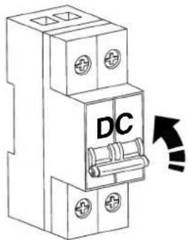
text_image
DC
text_image
AC- The unit will start. The LCD screen will turn on. The next section describes the steps that must be followed and the operation of the console.
Follow the steps below to stop and turn off the inverter:
- Disable the grid power supply. Without a grid, the unit will stop generating.
- Turn off the solar field supply. Activate the circuit breakers to cut off the photovoltaic power supply.
- Deactivate the inverter's switch/isolating switch and set it in the OFF position.
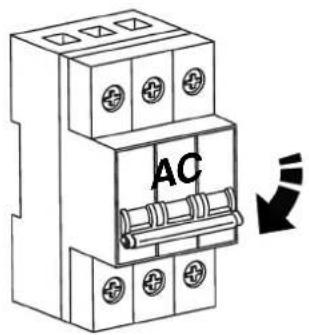
text_image
AC
text_image
DC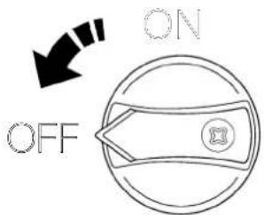
text_image
ON OFF- The unit will stop. When the internal capacitors of the DC bus are fully discharged and have no voltage, the LCD screen will turn off.
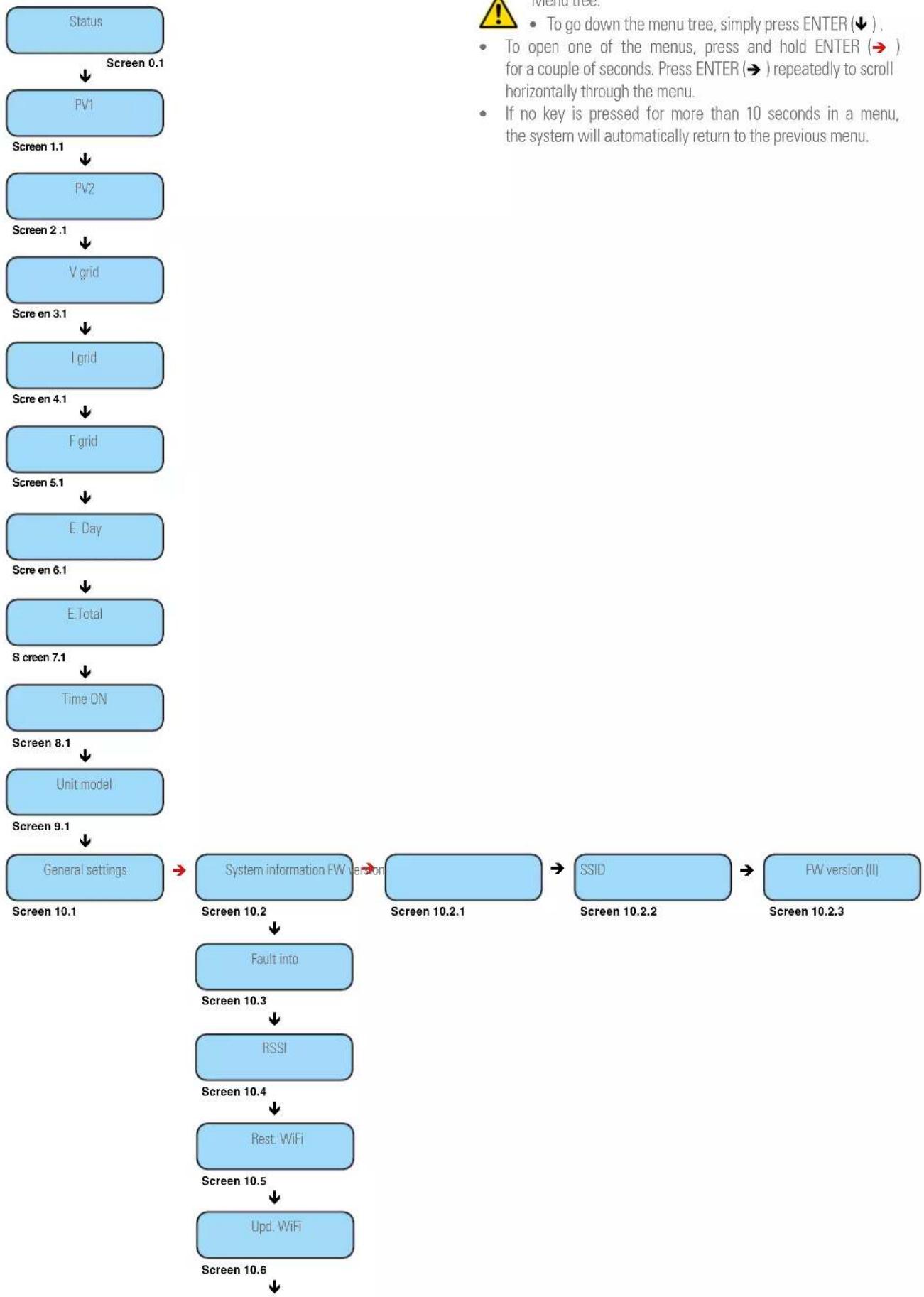
When the inverter is started, the following interfaces will be displayed on the OLED screen, which allows the user to check different types of operating information, as well as to change the inverter settings. Please refer to the following screen operation flow chart for more details:
1. "Status" screen menu.
Screen 0.1 Inverter status indicator and the power it is generating.
☐ "Waiting" status: The inverter is receiving power from the panels, but it does not detect a connection to the grid.
☐ "Verifying" status: The inverter is receiving power from panels and the grid, and is performing internal checks before start-up.
☐ "Generating" status: Under production and without anomalies.
2. "PV1" Screen menu.
Screen 1.1 Indicator of the voltage and intensity of the solar field connected to the MPPT 1.
3. "PV2" Screen menu.
Screen 2.1 Indicator of the voltage and intensity of the solar field connected to the MPPT 2 (Only for EQX2 3002-S, EQX2 4002-S, EQX 5002-S and EQX2 6002-S units).
4. "V grid" screen menu.
Screen 3.1 Indicator of the grid voltage.
5. "I grid" screen menu.
Screen 4.1 Indicator of the intensity supplied to the installation.
6. "F grid" screen menu.
Screen 5.1 Indicator of the grid frequency.
7. "E. Day" screen menu.
Screen 6.1 Indicator of the energy generated during the day.
8. "E. Total" screen menu.
Screen 7.1 Indicator of the energy that has been generated since the start-up of the inverter.
9. "Time ON" screen menu.
Screen 8.1 Indicator of the time that the inverter has been in operation since its start-up.
10. "Unit Model" screen menu.
Screen 9.1 Unit code indicator.
11. "General Settings" screen menu.
Screen 10.1 Main screen of the "General Settings" menu.
Screen 10.2 "Info.System" Inverter information.
Screen 10.2.1 Firmware version of the device. Continued 10.2.3.
Screen 10.2.2 SSID. WiFi identification.
Screen 10.2.3 FW version (II).
Screen 10.3 Fault Info. If the WiFi dongle is not connected, go to Screen...
Screen 10.4 RSSI. Indicator of the intensity of the WiFi signal received (Received Signal Strength Indicator).
Screen 10.5 Rest. WiFi. Reset the Wi-Fi settings.
Screen 10.6 Upd. WiFi. Update the unit via WiFi.
Screen 10.7 Safety UNE 217002.
Screen 10.7.1 EN50549.
Screen 10.7.2 Vietnam.
Screen 10.7.3 IEC (50 Hz).
Screen 10.7.4 IEC (60 Hz).
Screen 10.7.5 India.
Screen 10.7.6 Philippines.
Screen 10.7.7 Sri Lanka.
Screen 10.7.8 EN50549(Cz).
Screen 10.7.9 EN50549(Tr).
Screen 10.7.10 EN50549(Ie).
Screen 10.7.11 EN50549(Se).
Screen 10.7.12 EN50549(PI).
Screen 10.7.13 EN50549(Hr).
Screen 10.7.14 Belgium.
Screen 10.7.15 Fra mainland.
Screen 10.7.16 France (50 Hz).
Screen 10.7.17 France (60 Hz).
Screen 10.7.18 VDE0126.
Screen 10.7.19 50 Hz default.
Screen 10.7.20 60 Hz default.
Screen 10.7.21 VDE4105.
Screen 10.8 P. Limit ON/OFF. Function to limit the inverter power.
Screen 10.9 Rated P. Percentage injected into the grid. 0% for zero injection and 100% to dump surpluses into the grid.
Screen 10.10 Pow. Factor
Screen 10.11 CT ratio. Transformation ratio of the current transformer (CT).
Screen 10.12 Reconnection.
Screen 10.13 Modbus Addr.
Screen 10.14 Date/Time.
Screen 10.14.1 yyyy-mm-dd and hh:mm:ss.
Screen 10.15 Language.
Screen 10.15.0 Spanish Language
Screen 10.15.1 Portuguese language.
Screen 10.15.2 Polish language.
Screen 10.15.3 English language.
flowchart
graph TD
    A["Status"] --> B["Screen 0.1"]
    B --> C["PV1"]
    C --> D["Screen 1.1"]
    D --> E["PV2"]
    E --> F["Screen 2.1"]
    F --> G["V grid"]
    G --> H["Scre en 3.1"]
    H --> I["I grid"]
    I --> J["Scre en 4.1"]
    J --> K["F grid"]
    K --> L["Screen 5.1"]
    L --> M["E Day"]
    M --> N["Scre en 6.1"]
    N --> O["E Total"]
    O --> P["S creen 7.1"]
    P --> Q["Time ON"]
    Q --> R["Screen 8.1"]
    R --> S["Unit model"]
    S --> T["Screen 9.1"]
    T --> U["General settings"]
    U --> V["System information FW version"]
    V --> W["Screen 10.2"]
    W --> X["Fault into"]
    X --> Y["Screen 10.3"]
    Y --> Z["RSSI"]
    Z --> AA["Screen 10.4"]
    AA --> AB["Rest: WiFi"]
    AB --> AC["Screen 10.5"]
    AC --> AD["Upd: WiFi"]
    AD --> AE["Screen 10.6"]

flowchart
graph TD
    A["Safety 217002 UNE Screen 10.7"] --> B["EN50549 Screen 10.7.1"]
    B --> C["IEC (60 Hz) Screen 10.7.4"]
    C --> D["India Screen 10.7.5"]
    D --> E["Philippines Screen 10.7.6"]
    B --> F["Sri Lanka Screen 10.7.7"]
    F --> G["EN50549(Cz) Screen 10.7.8"]
    G --> H["EN50549(Tr) Screen 10.7.9"]
    F --> I["EN50549(Ie) Screen 10.7.10"]
    I --> J["EN50549(Se) Screen 10.7.11"]
    J --> K["EN50549(PI) Screen 10.7.12"]
    F --> L["EN50549(Hr) Screen 10.7.13"]
    L --> M["Belgium Screen 10.7.14"]
    M --> N["Fra mainland Screen 10.7.15"]
    F --> O["France (50 Hz) Screen 10.7.16"]
    O --> P["France (60 Hz) Screen 10.7.17"]
    P --> Q["VDE0126 Screen 10.7.18"]
    F --> R["50 Hz default Screen 10.7.19"]
    R --> S["60 Hz default Screen 10.7.20"]
    S --> T["VDE4105 Screen 10.7.21"]
    U["P. limit ON/OFF Screen 10.8"] --> V["Rated P. Screen 10.9"]
    V --> W["Pow. Factor Screen 10.10"]
    W --> X["CT ratio Screen 10.11"]
    X --> Y["Reconnection Screen 10.12"]
    Y --> Z["Modbus Addr. Screen 10.13"]
    Z --> AA["Date/Time Screen 10.14"]
    AA --> AB["yyyy-mm-dd hh:mm:ss Screen 10.14.1"]
    AB --> AC["Language Screen 10.15"]
    AC --> AD["Language: Spanish Screen 10.15.0"]
    AD --> AE["Portuguese language Screen 10.15.2"]
    AE --> AF["Language: Polish Screen 10.15.1"]
    AF --> AG["English language Screen 10.15.3"]
Fig. 44. Display menu tree.
7.3. ON-LINE MONITORING OF THE INSTALLATION.
The EQX2 inverter provides a monitoring port that can gather and transmit data from the inverter to the monitoring platform through an external monitoring device.
There are two methods available, via download and registration of the application (Fig. 45) and through the Configuration of the installation (plant) in the EQX-sun application (Fig. 46).
If there are download problems, contact your distributor or SALICRU's technical support.
7.3.1. Download and register the "EQX-sun" app.
Download the EQX-sun app and install it on the smartphone or tablet of the end user of the EQUINOX solar inverter.

text_image
EQX-sunThis process can take a few minutes. Once complete, open the EQX-sun app.
A home screen will appear to enter the credentials if you are already a user or to register a new user.
"Register" so that the application allows you to complete the necessary fields to process the registration and be able to use the application.

A demo version of the application is available. To open it, press the "Demo" button on the bottom of the screen.
② Once the registration process is complete, access the application by entering the credentials that have been defined by pressing the "Login" button.
If the email address or password entered is incorrect, the following error message will be displayed at the bottom of the screen:

③ If you have forgotten your password, click on "Recover password?" to open the following screen:

4 Enter the email address with which the plant was registered. A message with the sender "postmaster@kumo.salicru.com" and the subject "Equinox – Reset password" will be sent to that email address.
⑤ The message will include a 6-digit "Token" code. Enter the code on the code verification screen and press submit.

6 A screen will appear to enter a new password. You need to enter it twice. Press the "Save" button when finished.
The following confirmation message will be displayed:

7.3.2. Configuration of the installation (plant) in the EQX-sun app.
When the credentials are entered and the account is accessed, the main panel "My Plants" appears. The plants being created will appear in this panel.
To create a plant, press the "add" button (+) to the right of "My plants".
The "Plant Creation" panel will appear. All required fields must be completed.
Below is a full example for a plant located in a second residence in the Pyrenees:

text_image
≡ Mis Plantas + +
text_image
Creación de planta Información general Nombre de la planta* Tipo de planta* Selecciona uno Dirección* Buscar Avenida de la Sierra 100, 08640 - Benasque GMT +01:00 Amsterdam, Berlin If the photovoltaic installation is made up of 10 panels of 440 W each, the power of the solar field will be 440 x 10 = 4,400 Wp = 4.4 kWp. Potencia del campo fotovoltaico* (kWp) Euros (€) You have to enter the price per kWh consumed from the grid. For example, the retailer in this example charges a price of 0.14721 €/kWh. The price at which the retailer compensates for the kWh discharged into the grid must be entered. For example, the retailer in this example compensates it at a price of 0.0537 €/kWh. Información financiera Moneda* Selecciona uno Precio* (Moneda/kWh) Precio del kWh consumido de la red Compensación simplificada* (Moneda/kWh) Compensación por kWh inyectado a la red Crear plantaFig. 46. Creating the plant.
Once all the values have been entered, press the "Create plant" button.
Next, the app will indicate that the plant has been successfully created by means of a message at the bottom and a new header will appear in the "My plants" panel:

This monitoring mode only works during the hours of solar irradiance in which the inverter is running.
While the inverter is off, the app will not receive generation or consumption data.
7.3.3.1. Electrical diagram of the installation.
Make sure that the installation is as shown on the diagram in section 6.6. of page 19.
7.3.3.2. Configuring the installation on the app.

The inverter must be powered through the solar field at all times throughout the entire process.
Click on the plant that has been created to access its details:

For the time being, only the power of the solar field that has been entered will be displayed. The measurement instruments are not yet con-; this will be shown with the "Devices offline" age on the top of the synoptic chart.

The ESM1 EQX network analyser is already physically connected to the 485/WiFi 24H EQX unitation module, so it will only be necessary to be latter.
Add a device to the plant that has been created: press the "properties" button [●], to the right of the plant title.
The "Devices" panel will appear. The devices assigned to the plant will appear in this panel.

text_image
← Dispositivos + +To add the device (485/WiFi EQX2) communication module to the plant, press the "add" button [+] to the right of "Devices".
Next, select the 485/WiFi EQX2 device to start the pairing process.

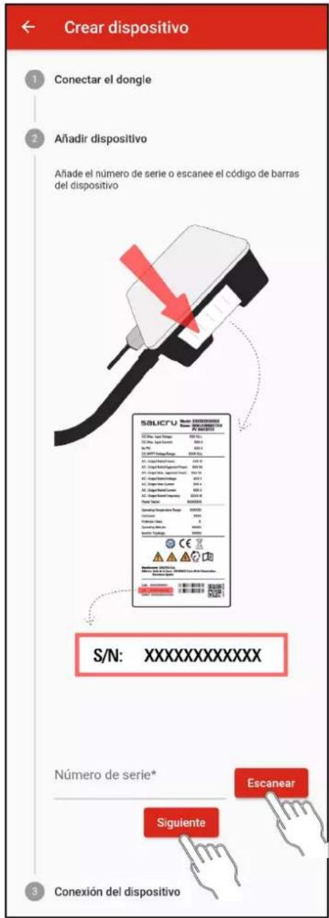
The pairing process has 3 steps:
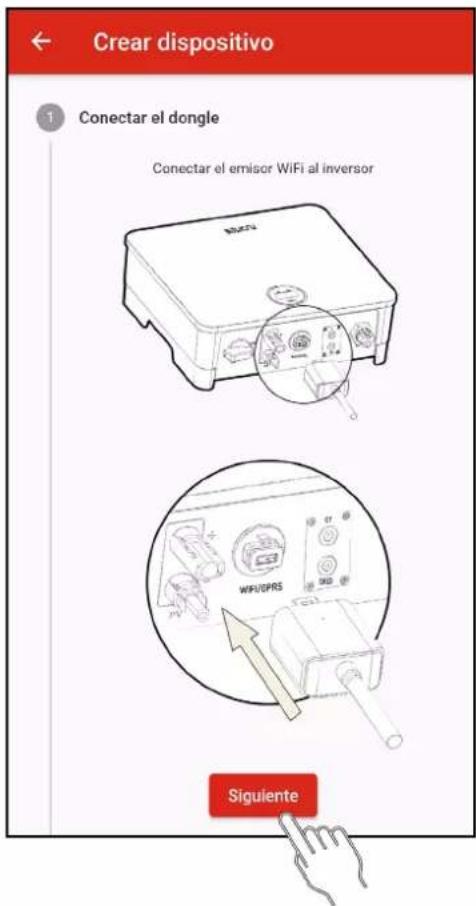
1. Connect the dongle:
a. Make sure that the dongle is plugged into the unit's USB port.
b. Press the "Next" button.
You must link the inverter's serial number to add the unit to the plant.
a. Press the "Scan" button.
The smartphone or tablet may request permission to use the camera. Permission is required.
b. Move the camera closer to the barcode that appears on the inverter label. When the code is detected, the scanner will close and the serial number will be written automatically.
Check that the serial number corresponds to the one on the label.
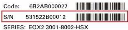
text_image
Code: 6B2AB000027 S/N 531522B00012 SERIES: EQX2 3001-8002-HSX
Fig. 47. Example of a barcode identification label.
If you do not have a camera or it does not detect the barcode correctly, type the serial number marked with a red box in the indicated field.
c. Press the "Next" button.
When adding the device, two situations can occur:
1: The device is added successfully. This is indicated with the following message:

2: The device you are trying to add is already registered. This is indicated with the following message:

3. Device connection.
Once the dongle has been paired to the corresponding plant, you have to configure the WiFi network of the installation to which it has to connect to access the server and update the application data.
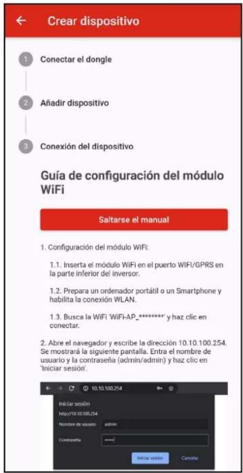
Follow the steps shown in the application or in the annex (section 11) of this manual.
7.3.4. "24h" monitoring. (Day and night).

Optional devices 6B20P000018 (485/WIFI 24H EQX2-T) and 6B20P000017 or 16 (ESM3T 90A or 300A EQX2)
are required.
Unlike the previous mode, this monitoring mode can also be used to monitor the consumption of the installation if the inverter is not running and/or at night.
For more information, refer to the "EL18800" manual.
7.3.5. Operation of the EQX-sun app.
7.3.5.1. Home screen "My Plants".
The EQX-sun application organises the different installations under the name "Plants". In the example of section 8 "Installation configuration (plant) in the EQX-sun application" a plant called "Chalet Pirineos" has been created. If other installations are created in the future, they will appear in the list in alphabetical order.
Information provided by the plant header:
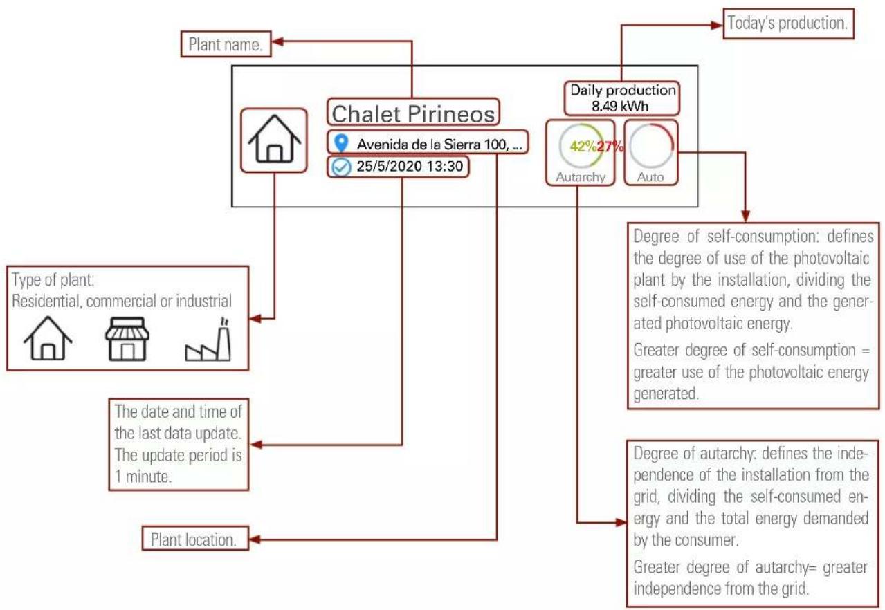
flowchart
graph TD
    A["Plant name"] --> B["Chalet Pirineos"]
    B --> C["Daily production 8.49 kWh"]
    C --> D["Today's production"]
    B --> E["Type of plant: Residential, commercial or industrial"]
    B --> F["The date and time of the last data update. The update period is 1 minute."]
    B --> G["Plant location."]
    B --> H["Degree of self-consumption: defines the degree of use of the photovoltaic plant by the installation, dividing the self-consumed energy and the generated photovoltaic energy.<br>Greater degree of self-consumption = greater use of the photovoltaic energy generated."]
    B --> I["Degree of autarchy: defines the independence of the installation from the grid, dividing the self-consumed energy and the total energy demanded by the consumer.<br>Greater degree of autarchy= greater independence from the grid."]
7.3.6. Individual plant screen.
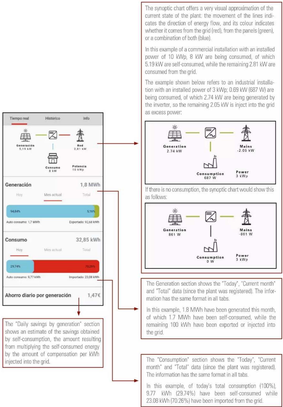
Each plant has three tabs at the top: "Real time", "Historical" and "Info".
- Information shown in the "Real Time" tab:
This tab is divided into 4 sections: synoptic, generation, consumption and daily savings by generation.
- Information shown in the "History" tab:
This tab is divided into 4 sections: "Plant performance", "Comparison of generated energy", "Economic savings" and "Environmental impact".
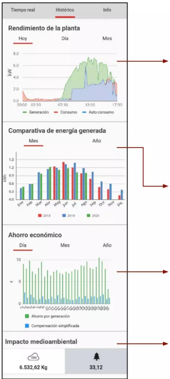
bar
| Metric | 2018 (kWh) | 2019 (kWh) | 2020 (kWh) | | :--- | :--- | :--- | :--- | | Ene | 0.5 | 0.4 | 0.3 | | Feb | 0.6 | 0.7 | 0.6 | | Mar | 0.9 | 1.0 | 0.9 | | Abr | 1.1 | 1.2 | 1.1 | | May | 1.2 | 1.3 | 1.2 | | Jun | 1.1 | 1.4 | 1.3 | | Jul | 1.0 | 1.3 | 1.2 | | Ago | 0.9 | 1.1 | 1.0 | | Sep | 0.7 | 0.8 | 0.9 | | Oct | 0.5 | 0.6 | 0.6 | | Nov | 0.3 | 0.4 | 0.5 | | Dec | 0.2 | 0.3 | 0.4 | Timeframe: Tiempo real, Histórico, Info; Rendimiento de la planta; Comparativa de energía generada; Ahorro económico; Impacto medioambiental; Ahorro economico; Ahorro por generación; Compensación simplificada.The "Plant Performance" section shows the "Today", "Day" and "Month" information. The "Today" tab shows a chart with the real-time instantaneous generation, consumption and self-consumption values, while the "Day" tab shows the sum of the instantaneous values of the previous chart. The "Month" tab shows the total values of the previous days.
The colour key of the chart follows the same pattern, as the synoptic chart: Red shows the energy consumed from the grid. Green shows the energy generated by the photovoltaic panels. Blue shows the self-consumption: the consumption of energy generated from the photovoltaic panels instead of from the grid.
You can enlarge specific areas on the chart by pinching the screen with two fingers and spreading them out. Close them back again to return to the original image.
The different charts can be hidden or displayed by clicking on the "Generation", "Consumption" and "Self-consumption" buttons.
The data in "Comparison of generated energy" can be grouped by months or years. This example shows the monthly production of a plant created in the month of May 2018 and the production until the current month, which is supposed to be August 2020.
Comparing months of different years can be very useful to detect problems in a photovoltaic installation, or even to have an idea of the degradation of the panels.
The “Economic savings” section shows charts with the approximate values of “Savings per generation” (amount obtained by multiplying the generation by the price of kWh consumed) and “Simplified compensation” (amount obtained by multiplying the generation injected into the multiplied by the price of kWh injected).
The savings in terms of CO2 emissions and their equivalence in number of trees planted can be seen in the "Environmental impact" section.
In a conventional installation, each kWh generated using fossil fuels generates greenhouse gas emissions. These gases are classified as gases with a "carbon footprint" and they are converted into an equivalent in carbon dioxide (CO2). Therefore, the value shown is the amount of CO2 emissions that an equivalent fossil fuel system would have generated to produce the energy that the system (plant) has generated with renewable energy.
Moreover, trees absorb CO2 and this is why they are used in many different reforestation projects worldwide to counteract CO2 levels. By using renewable energy sources, the level of CO2 that trees have to absorb is reduced. The number of trees displayed would be equivalent to the new trees that would need to be planted.
- Information shown in the "Info" tab:
This tab shows the plant information with the values with which it was created. Any field can be modified by pressing the "properties" button [‡], to the right of the plant title and then, in the drop-down menu, by clicking the "Edit" button.
When the retailer changes its electricity rates, the price per kWh must also be edited, for example.
8. TROUBLESHOOTING GUIDE
8.1. ERROR MESSAGES.
The single-phase inverter of the EQX2 series has been designed in compliance with the applicable grid operation standards and complies with the corresponding safety and EMC requirements. The inverter has gone through a series of rigorous tests to ensure its sustainable and reliable operation before shipment.
When a fault occurs, the corresponding error message will be displayed on the OLED screen, and the inverter may, in this case, stop injecting power into the grid. The error messages and their corresponding troubleshooting methods are listed below:
| Error message | Description Solution | |
| No display | No image on the display | - Check that all cables are firmly connected and that the DC switch is turned on.- Check that the input voltage coincides with the working voltage. |
| Network lost or not detected | Grid fault, AC switch or circuit disconnected. | - Check that there has been a grid fault.- Check that the AC thermal-magnetic circuit breaker switches are up and that the terminals are correctly connected. |
| Grid voltage fault | Overvoltage or undervoltage, mains voltage higher or lower than the set protection value. | - Check that the safety regulation setting is correct.- Check the grid voltage. If the grid voltage exceeds the permitted range of inverter protection parameters, contact the local power company.- Check whether the impedance of the AC cable is too high. Replace the cable with a thicker one if this is the case. |
| Grid frequency fault | Excessively high or low grid frequency with regards to the protection threshold set forth. | - Check whether the safety rule settings are correct or not.- Check the grid frequency. If it exceeds the permitted range of inverter protection parameters, contact the local power company. |
| Regarding the ISO limits | Low system insulation resistance, usually due to poor module/cable insulation to earth or in rainy and humid environments. | - Check if the photovoltaic panels, cables and connectors are broken or there are water leaks.- Check if there is a reliable earthing connection. |
| CFGI error | Excessive leakage current. | - Excessively high earth current.- Check the photovoltaic cable to see if it is short-circuited to earth. |
| Photovoltaic overvoltage | The voltage of the photovoltaic system is excessively high. | - The input voltage is excessively high.- Reduce the number of photovoltaic panels to ensure that the open-circuit voltage of each string is less than the maximum input voltage allowed. |
| Excessive inverter temperature | The temperature inside the inverter is excessively high and out of the safe range. | - Check if the inverter is exposed to direct sunlight.- Reduce the ambient temperature. |
| Error message | Description Solution | |
| DCI error | Excessively high DC injection. The inverter detects a high DC component on the AC output. | - Restart the inverter; wait a few seconds until it is restored back to normal.- If the fault occurs several times, please contact SALICRU. |
| Bus voltage error | Excessively high bus voltage. | |
| ICS error | Internal communication error, possibly due to a strong external magnetic field, etc. | |
| SPI error | ||
| E2 error | ||
| Error in the GFCI device | Anomaly in the GFCI device. | |
| AC transducer error | Anomaly in the AC transducer. | |
| Relay test failed | Relay self-test failure. Neutral and earth are not connected properly on the AC side or simply fail. | - Use a multimeter to check if the voltage is high (it should be less than 10 V) between N and PE on the AC side. If the voltage is higher than 10 V, the neutral and earth are not well connected on the AC side. Alternatively, restart the inverter.- If neutral and earth are connected properly, contact SALICRU. |
| Flash memory error | Error in the internal storage, possibly due to a strong external magnetic field, etc. | - Restart the inverter; wait a few seconds until it is restored back to normal.- If the fault occurs several times, please contact SALICRU. |
| External fan failure | Anomaly in the external fan. | - Stop the inverter and disconnect the AC+DC cables.- Check if the fan is being blocked by unwanted objects. If not, replace it. |
| Internal fan failure | Anomaly in the internal fan. | - Restart the inverter; wait a few seconds until it is restored back to normal.- If the fault occurs several times, please contact SALICRU. |
Tab. 12. Error messages.
The red LED will be lit on the display for all error messages (see Fig. 55).
8.2. TROUBLESHOOTING.
| Problem Solution | |
| The inverter is powered correctly but it does not start and the message "Waiting" appears on the display while the green LED flashes. | To start the inverter, in addition to receiving voltage on the panels, it needs to be connected to the grid to synchronise with it and ensure that it does not work in the "island" mode.Check that there is voltage on the terminals of the circuit breakers that power the inverter protection panel.If the circuit breakers on the AC protection panel are activated correctly, there might be another circuit breaker upstream that needs to be activated. |
| Zero injection is activated and the inverter does not generate power, even though the installation has load. | The CT may be wired incorrectly. The CT arrow must be in the direction of the installation towards the grid (connection side).Read section "6.5.3. Installing the CT." |
| The red LED is flashing, but the inverter is working properly. | The inverter only indicates that it does not detect the WiFi antenna. However, the inverter is working properly. |
| At night, no data appears in the EQX-sun application. | The inverter is powered by the solar panels. Therefore, if the solar irradiance is not high enough for the inverter to start, it will not be able to power the WiFi antenna to send the data required to update the application.In order to monitor the installation 24 hours a day, it is necessary to install the optional devices 6B2OP000007 (485/WiFi 24H EQX) and 6B2OP000008 (ESM1 EQX). |
| I do not wish to connect the inverter to the WiFi network. Would this pose a problem? | The inverter will work perfectly, since it does not need to be connected to the Internet. In addition, the most relevant generation data are shown on the unit's display.The WiFi antenna is only used to provide installation data to the user as a means of providing additional information and to manage and control the system more easily. |
Tab. 13. Troubleshooting.
8.3. MAINTENANCE.
| Danger | Risk of causing damage to the inverter or personal injury due to improper use.Before using the inverter, observe the following procedure:- Lower the AC thermal-magnetic circuit breaker and the inverter DC switch.- Wait at least 5 minutes for the internal capacitors to be fully discharged.- Check that there is no voltage or current before removing a connector. |
| Warning | Keep all unqualified staff far from these areas!A temporary warning sign or barrier should be posted to keep unqualified persons away while performing electrical connection and service work. |
| Attention | Restart the inverter only after removing the fault that affects safety. Never replace internal components at random.Please contact SALICRU for support regarding the maintenance tasks. Otherwise, SALICRU shall not be held liable for any damage caused. |
| Note | Perform the maintenance tasks on the unit as described in the manual and always using the corresponding tools, test equipment, or the latest version of the manual. |
| Items Methods Period | ||
| Cleaning the system | - Check the temperature and dust accumulated in the inverter.- Clean the inverter housing, if needed.- Check whether air is coming in and out of the unit normally or not.- Clean the air inlet and outlet, if needed. | Six months to a year, depending on the amount of dust in the air, |
Tab. 14. Maintenance tasks.
9. TECHNICAL FEATURES.
9.1. 2 MPPT UNITS.
| Model | EQX24002-T | EQX25002-T | EQX26002-T | EQX28002-T | EQX210002-T | EQX212002-T | EQX215002-T | EQX217002-T | EQX220002-T | EQX225002-T |
| Input | ||||||||||
| Star-up voltage (V) 180 | ||||||||||
| Max. DC voltage (V) 1100 | ||||||||||
| Rated DC voltage (V) 620 | ||||||||||
| MPPT voltage margin (V) 160-1000 | ||||||||||
| No. of MPPT trackers 2 | ||||||||||
| No. of DC inputs on each MPPT 1,1 2/2 | ||||||||||
| Max. current (A) | 15/15 | 20/20 | 15/15 | 15/30 | 30/30 | 30/30 | 30/30 | |||
| Max. short circuit current (A) | 20/20 | 20/40 | 40/40 | |||||||
| String feedback current (A) | 0 | |||||||||
| Output | ||||||||||
| Rated power (W) | 4000 | 5000 | 6000 | 8000 | 10000 | 12000 | 15000 | 17000 | 20000 | 25000 |
| Max. power (W) | 4400 | 5500 | 6600 | 8800 | 11000 | 13200 | 16500 | 18700 | 22000 | 25000 |
| Rated apparent power AC (VA) | 4000 | 5000 | 6000 | 8000 | 10000 | 12000 | 15000 | 17000 | 20000 | 25000 |
| Max. apparent power (AC) | 4000 | 5000 | 6600 | 8800 | 11000 | 13200 | 16500 | 18700 | 22000 | 250000 |
| Rated voltage (V) | 3/N/PE, 230 / 400 | |||||||||
| Rated frequency (Hz) | 50/60 | |||||||||
| Rated AC current (A) | 5,8 | 7,3 | 8,7 | 11,6 | 14,5 | 17,4 | 21,7 | 24,6 | 29 | 36,2 |
| Max. AC current (A) | 6,7 | 8,4 | 10 | 13,3 | 16,5 | 20 | 25 | 28,4 | 31,9 | 39 |
| Instantaneous current measured | 7 A at 4.4 ms. | 8.5 A at 4 ms. | ||||||||
| Max. fault current (A) | 33 | 40 | 66 | 76 | ||||||
| Max. overcurrent protection (A) | 33 | 40 | 66 | 76 | ||||||
| Power factor | 0.8 ind. .. 0.8 cap. | |||||||||
| Total max. harmonic distortion | <3% at Rated pow. | |||||||||
| DCI | <0.5% In | |||||||||
| Efficiency | ||||||||||
| Maximum (%) | 98,1 | 98,3 | 98,6 | |||||||
| European (%) | 97,9 | 98 | 98,2 | |||||||
| MPPT (%) | 99,9 | |||||||||
| Protection | ||||||||||
| Against reverse DC polarity | Built-in | |||||||||
| Insulation resistance | Built-in | |||||||||
| DC switch | Built-in | |||||||||
| Overvoltage | Built-in | |||||||||
| Excessively high temperature | Built-in | |||||||||
| Residual current | Built-in | |||||||||
| Island | Frequency shift, built-in | |||||||||
| AC short-circuit | Built-in | |||||||||
| Overvoltage | Built-in | |||||||||
| General data | ||||||||||
| Dimensions (D x W x H, mm.) | 175 x 550 x 410 | |||||||||
| Weight (kg) | 23 | 26 | 29 | |||||||
| Degree of protection | IP65 | |||||||||
| Night self-consumption (W) | <1 | |||||||||
| Topology | Transformerless | |||||||||
| Operating temperature (°C) -30 to 60 | ||||||||||
| Relative humidity 0 - 100% | ||||||||||
| Maximum altitude (m.) 3000 | ||||||||||
| Cooling Natural convection | ||||||||||
| Noise level (dB) < 25 < 40 | ||||||||||
| Display OLED & LED | ||||||||||
| Communication RS485/WiFi (Optional) | ||||||||||
| Standards | NB/T32004, IEC62109, IEC62116, VDE4105, VDE0126, UTE C15-712-1, AS4777, C10/11, CE10-21, UNE 217002, NBR16149, IEC61727, IEC60068, IEC61683, EN50549 and EN61000 | |||||||||
Tab. 15. Technical features.
9.2. 4 AND 10 MPPT UNITS.
| Model | EQX2 33004-T | EQX2 40004-T | EQX2 50004-T | EQX2 60004-T | EQX2 100010-T |
| Input | |||||
| Star-up voltage (V) | 180 | 200 | |||
| Max. DC voltage (V) | 1100 | ||||
| Rated DC voltage (V) | 620 | ||||
| MPPT voltage margin (V) | 180-1000 | 200-950 | |||
| No. of MPPT trackers | 4 | 10 | |||
| No. of DC inputs on each MPPT | 2 | 2/2 | |||
| Max. current (A) | 26/26/26/26 | 10*26 | |||
| Max. short circuit current (A) | 40/40/40/40 | 10*40 | |||
| String feedback current (A) | 0 | ||||
| Output | |||||
| Rated power (W) | 33000 | 40000 | 50000 | 60000 | 110000 |
| Max. power (W) | 36000 | 44000 | 55000 | 66000 | 121000 |
| Rated apparent power AC (VA) | 33000 | 40000 | 50000 | 60000 | 110000 |
| Max. apparent power (AC) | 36000 | 44000 | 55000 | 66000 | 121000 |
| Rated voltage (V) | 3 / N / PE, 380 / 400 V | ||||
| Rated frequency (Hz) | 50/60 | ||||
| Rated AC current (A) | 47,8 | 58 | 72,5 | 87 | 158,8 |
| Max. AC current (A) | 52,6 | 63,8 | 79,7 | 95,3 | 174,8 |
| Instantaneous current measured (A) | 16.5 A at 10.6 ms | 28.4 A at 3.8 ms | |||
| Max. fault current (A) | 118 | 160 | 180 | 180 | 300 |
| Max. overcurrent protection (A) | 118 | 160 | 180 | 180 | 300 |
| Power factor | 0.8 capacitive to 0.8 inductive | ||||
| Total max. harmonic distortion | <3% @ Rated power | ||||
| DCI | <0.5% In | ||||
| Efficiency | |||||
| Maximum | 98,1% | 98,8% | |||
| European 97,5% | 98,3% | ||||
| MPPT | 99,9% | ||||
| Protection | |||||
| Against reverse DC polarity | Built-in | ||||
| Insulation resistance | Built-in | ||||
| DC switch | Built-in | Optional | |||
| Overvoltage | Built-in | ||||
| Excessively high temperature | Built-in | ||||
| Residual current Built-in | |||||
| Island Frequency shift, built-in | |||||
| AC short-circuit Built-in | |||||
| Overvoltage Built-in | |||||
| PID protection - Optional | |||||
| General data | |||||
| Dimensions (D x W x H, mm.) 270 x 600 x 400 290 x 975 x 680 | |||||
| Weight (kg) 42 | 82 | ||||
| Degree of protection | IP65 | ||||
| Night self-consumption (W) | <1 | ||||
| Topology | Transformerless | ||||
| Operating temperature (°C) | -30 to 60 | ||||
| Relative humidity | 0 - 100% | ||||
| Maximum altitude (m.) | 3000 | ||||
| Cooling | Natural convection | Smart ventilation | |||
| Noise level (dB) | <25 | - | |||
| Display | OLED & LED | ||||
| Communication RS485/WiFi (Optional) | |||||
| Standards | NB/T32004, IEC62109, IEC62116, VDE4105, VDE0126, UTE C15-712-1, AS4777, C10/11, CEI0-21, UNE 217002, NBR16149, IEC61727, IEC60068, IEC61683, EN50549 and EN61000 | ||||
10. ANNEX. WIFI MODULE SETUP.
The WiFi module must be configured in the router during the first installation process. If the name or password of the router is changed, the WiFi password must be configured again.
- WiFi module setup.
a. Start the inverter.
b. Prepare a laptop computer or smartphone and activate the WLAN/WiFi connection.
c. Go to screen 10.2.2 SSID to identify the WiFi network name of the Inverter.
d. On the laptop or smartphone, search for the WiFi with the name "WiFi-AP**********" and select it to connect.
- Open the browser and type the address 10.10.100.254. The following screen will be displayed, enter the user name "admin", password "admin" and click on "Login". See Fig. 48.
1) The * correspond to the last 8 digits of the inverter's S/N.
Fig. 49. Interface system.
- Click on "STA Setting" to open the Interface Wi-Fi setup. If this is the first time entering the system, the screen on Fig. 31 will be shown.
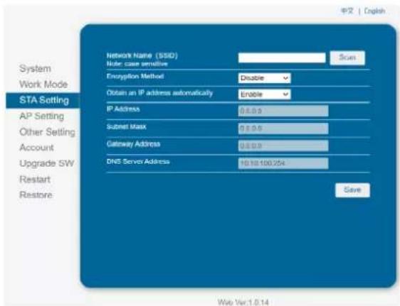
text_image
System Work Mode STA Setting AP Setting Other Setting Account Upgrade 5W Restart Restore Network Name ($SID) Node case sensitive Scan Encryption Method Disable Obtain an IP address automatically Enable IP Address 0.0.0 Submit Mask 0.0.0 Gateway Address 0.0.0 DNS Server Address 10.10.100.254 Save Web Ver.1.0.14Fig. 50. WiFi setup interface.
However, if it has been previously configured, the screen shown in Fig. 32 will appear. Click on "Scan" to display a list of available WiFi networks.
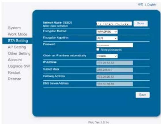
text_image
System Work Mode STA Setting AP Setting Other Setting Account Upgrade SW Restart Restore Network Name (SSD) Note: case sensitive SSD search: http://action Scan Encryption Method WPA2PSK Encryption Algorithm AES Password ****** Show passwords Obtain an IP address automatically Enable IP Address 172.26.12.82 Submit Mask 285.285.0.0 Gateway Address 172.26.26.12 DNS Server Address 172.12.16.88 Save Web Var 1.0.14Fig. 51. WiFi setup interface.
- Select the desired WiFi and click on "OK". It only supports 2.412GHz-2.484GHz routers. See Fig. 52.
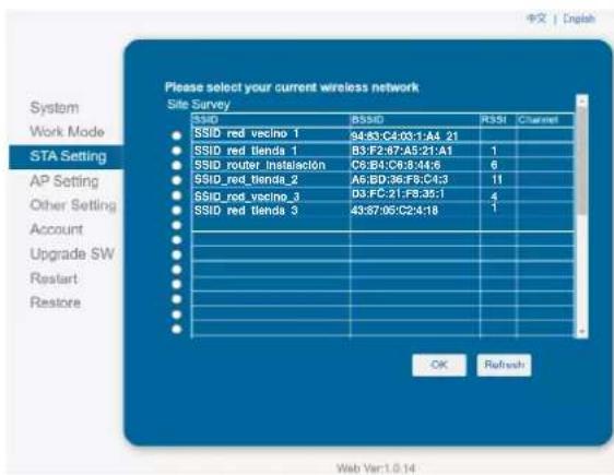
text_image
Please select your current wireless network Site Survey SSID BSIID R3SI CChannel SSID red vecino 1 94:83:C4:03:1:A4_21 SSID red blenda 1 B3:F2:67:A5:21:A1 1 SSID router instalación C5:B4:C8:8:44:6 6 SSID_red_blenda_2 A5:BD:36:F6:C4:3 11 SSID_red_vecino_3 B3:F,C:21:F8:35:1 4 SSID Red blenda 3 43:87:05:C24:18 1 OK Refresh Web Var:1.0.14Fig. 52. Selecting the WiFi network.
- Next, a pop-up message will appear to remind you to enter the WiFi password, click on "Accept". See Fig. 53.

text_image
10.10.100.254 dice The password is empty! AceptarFig. 53. Password reminder screen.
- Enter the password in the blank box and click on "Save". See Fig. 54.

text_image
System Work Mode STA Setting AP Setting Other Setting Account Upgrade SW Restart Restore Network Name (SSID) Member name sensitive SSID user instruction Scan Encryption Method WPA2PSK Encryption Algorithms AES Password Show passwords Obtain an IP address automatically Enable IP Address 172.26.12.82 Submit Mask 205.265.0.0 Gateway Address 172.26.26.12 DNS Server Address 172.12.16.85 Save Web Var:1.0.14Fig. 54. Save password screen.
- The system will show the message "Saved Successfully". Click on "Restart" to complete the WiFi setup. See Fig. 55.
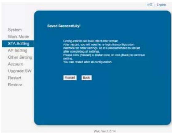
text_image
System Work Mode STA Sotting AP Setting Other Setting Account Upgrade SW Restart Restore Saved Successfully! Configurations will take effect after restart. After restart, you will need to re-login the configuration interface for other settings, so it is recommended to restart after completing all settings. Please click (restart) to restart now, or click (back) to continue setting. You can restart after all configuration. Restart Back Web Ver.1.0.14Fig. 55. WiFi setup saved.
- Once the setup is complete, the WiFi ON indicator on the module will be activated.
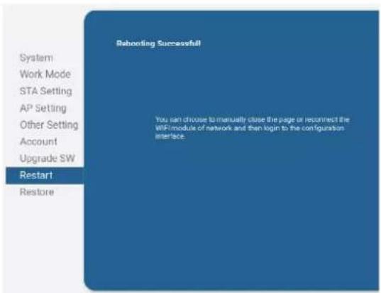
text_image
Rebooting Successful System Work Mode STA Setting AP Setting Other Setting Account Upgrade SW Restart Restore You can choose to manually close the page or reconnect the WIF/module of network and then login to the configuration interface.Fig. 56. Completed WiFi setup.


salicru
Information about the technical support and service network (TSS), the sales network and the warranty is available on our website:
www.salicru.com
Product range
Uninterruptible Power Supplies (UPS)
Variable Frequency Drives (VFDs)
Power supplies
Static inverters
Transformers and Autotransformers
Voltage stabilisers
Photovoltaic inverters

@salicru_SA

www.linkedin.com/company/salicru