
EC0463 - Digital timer switch IFM - Free user manual and instructions
Find the device manual for free EC0463 IFM in PDF.


| Product Type | Digital Timer Switch |
| Model | EC0463 |
| Brand | IFM |
| Dimensions (H x W x D) without cover | 163 x 112 x 25.5 mm |
| Weight | 0.30 kg |
| Operating Voltage | 8...32 V DC |
| Current Consumption | 45 mA (at 24 V DC) |
| Protection Rating | IP 20 (with cover and cable seal IP 54) |
| Operating Temperature | -40...85 °C |
| Storage Temperature | -40...85 °C |
| Processor | Freescale PowerPC, 50 MHz |
| Memory (total) | 208 Kbytes RAM / 1536 Kbytes Flash / 1 Kbyte FRAM |
| Number of Inputs | 12 (configurable) |
| Number of Outputs | 8 (configurable) |
| CAN Interfaces | 2 (CANopen, SAE J1939, or free protocol) |
| Programming System | CODESYS 2.3 (IEC 61131-3) |
| Input Configurations | Digital, analogue (0-10/32 V, 0-20 mA, ratiometric), frequency |
| Output Configurations | Positive switching (high side), PWM, diagnosis |
| Installation | Fixing by 4 M4 screws to DIN 912 or DIN 7984 and 4 tubular rivets |
| Connection | AMP blade male terminals 6.3 mm, core cross-section 0.5...2.5 mm² |
| Maintenance and Cleaning | Clean with a dry, lint-free cloth; do not use solvents or abrasive cleaners |
| Safety Precautions | Protect from moisture and excessive heat; follow wiring diagram; ensure correct polarity |
| Spare Parts and Repairability | Contact IFM service for spare parts; device is not user-serviceable |
| General Information | CE and E1 approved; electromagnetic compatibility per EN 61000-6-2 and EN 61000-6-4 |
Frequently Asked Questions - EC0463 IFM
User questions about EC0463 IFM
0 question about this device. Answer the ones you know or ask your own.
Ask a new question about this device
Download the instructions for your Digital timer switch in PDF format for free! Find your manual EC0463 - IFM and take your electronic device back in hand. On this page are published all the documents necessary for the use of your device. EC0463 by IFM.
USER MANUAL EC0463 IFM
natural_image
Technical line drawing of a mechanical housing or enclosure with internal compartments and mounting points (no text or symbols)Spis treści
1 Uwaga wstępna 4
natural_image
Front view line drawing of a portable electronic device with control buttons and ventilation grilles (no text or symbols)natural_image
Technical line drawing of a mechanical component with hatched fill (no text or symbols)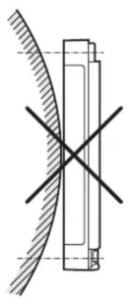
natural_image
Pure technical diagram showing intersecting lines and a curved interface (no text or symbols)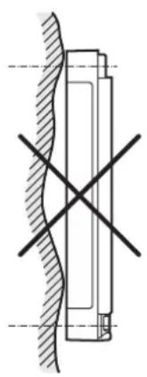
natural_image
Pure mechanical cross-section diagram without any text, numbers, or symbols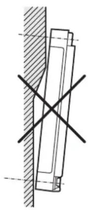
natural_image
Technical drawing of a mechanical component with crosshair alignment lines (no text or symbols)natural_image
Pure mechanical assembly diagram showing a vertical wall, rectangular components, and directional arrows without any text or symbols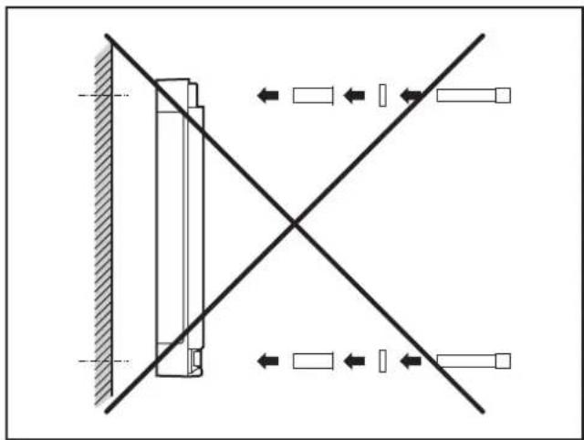
natural_image
Pure mechanical diagram showing a vertical component with diagonal lines and directional arrows, no text or symbols present.Użycie tuleji.
natural_image
Technical line drawing of a rectangular electronic component with internal channels and mounting holes (no text or symbols)Spód urządzenia
natural_image
Technical line drawing of a device rear panel with internal compartments and mounting holes (no text or symbols)natural_image
Technical line drawings of a door frame assembly, showing three sequential steps with no text or symbols1: BasicController / BasicController plus
2: pokrywa
natural_image
Technical line drawing of a device housing with internal compartments and a separate panel (no text or symbols)www.ifm.com → Service → Download → Control systems*
Mobile controller BasicController
12 inputs
8 outputs
2 CAN interfaces
Programming
to IEC 61131-3
8...32 V DC
CE


E1
| Technical data | Modular control systemUsable as CANopen controller or intelligent I/O module |
| Mechanical data | |
| Housing | plastic housing (black) |
| Dimensions (H x W x D)without coverwith EC0401 coverwith EC0402 cover and BasicDisplayCR0451 | 163 x 112 x 25.5 mm163 x 112 x 68 mm163 x 112 x 73.4 mm |
| Installation | fixing by means of 4 M4 screws to DIN 912 or DIN 7984 and 4 tubular rivets to DIN 7340 (tubular rivets are supplied) |
| Connection | AMP blade male terminals 6.3 mm, to be clipped into place and thus vibration-resistant, protected against reverse polaritycontacts AMP timer, CuZn pre-tin-platedcore cross-section 0.5...2.5 mm^2 |
| InputsOutputsOperating voltage , CAN bus | 3 x 8-pole2 x 8-pole1 x 6-pole, 1 x 4-pole |
| Protection rating | IP 20 (with cover and cable seal IP 54) |
| Operating/storage temperature | -40...85°C / -40...85°C |
| Weight | 0.30 kg |
| Electrical data | |
| Operating voltage | 8...32 V DC |
| Current consumption | 45 mA (at 24 V DC) |
| OvervoltageUndervoltage detectionUndervoltage shutdown | 36 V for t ≤ 10 sat U_B ≤ 7.8 Vat U_B ≤ 7.0 V |
| Processor | Freescale PowerPC, 50 MHz |
| Memory (total) | 208 Kbytes RAM / 1536 Kbytes Flash / 1 Kbyte FRAM |
| Memory allocation | see BasicController system manualwww.ifm.com → data sheet search → e.g. CR0401 → Additional data |
| Device monitoring | undervoltage monitoringwatchdog functionchecksum test for program and systemexcess temperature monitoring |
CR0401 Technical data
CAN interfaces 1/2
Baud rate
Communication profi le
Software/programming
Programming system CODESYS version
Inputs 12 (configurable),
Configurations
Outputs 8 (confi gurable),
Configurations
Status LED two-colour LED (red/green)
Operating states (preset)
CAN interface 2.0 A/B, ISO 11898
20 kBit/s...1 MBit/s (default CAN1: 250 kBit/s, CAN2: 250 kBit/s)
CANopen, CiA DS 301 version 4, CiA DS 401 version 1.4
or SAE J 1939 or free protocol
2.3 (IEC 61131-3)
Number Version
| 4 digital for positive / negative sensor signals analogue (0...10/32 V DC, 0..20 mA, ratiometric) frequency (≤ 30 kHz) | B_L/B_H AFRQ |
| 4 digital for positive sensor signals resistance measurement (0,016...3.6 kΩ) | B_L |
| 4 digital for positive sensor signals B | L |
positive sensor signals have diagnostic capabilities
Number Version
| 2 positive | switching (high side)PWM output (20...250 Hz), 2 A, diagnosis | B_H PWM |
| 4 positive | switching (high side)PWM output (20...250 Hz), 1 A | B_H PWM |
| 2 positive | switching (high side)PWM output (20...250 Hz), 4 A, diagnosis | B_H PWM |
Colour Status Description
| – permanently off no operating voltage | ||
| orange | 1 x on | initialisation or reset checks |
| green | 5 Hz no operating system loaded | |
| 2 Hz application is running (RUN) | ||
| permanently on | application stopped (STOP) | |
| red | 10 Hz | application stopped (STOP with error) |
| 5 Hz application stopped due to undervoltage | ||
| permanently on | system fault (fatal error) | |
CR0401 Technical data
Characteristics of the inputs
Analogue inputs (A)
Connection A: 02, 03, 06, 07
IN0...IN3
can be configured as:
Digital input (B _L )
Connection B: 02, 03, 06, 07
IN4...IN7
can be configured as...
| Voltage inputs | |
| Input voltage 0...10 V or 0...32 V | |
| Resolution 12 bits | |
| Accuracy ± 1% FS | |
| Input resistance 65.6 kΩ (0...10 V), 50.7 kΩ (0...32 V) | |
| Input frequency ≤ 500 Hz | |
| Current inputs, with diagnostic capability | |
| Input current 0...20 mA | |
| Resolution 12 bits | |
| Accuracy ± 1% FS | |
| Input resistance 400 Ω | |
| Input frequency ≤ 500 Hz | |
| At a current of >23 mA the input is switched to the voltage input! | |
| Voltage inputs, 0...32 V, ratiometric | |
| Function (U) | IN + UB) x 1000 %o |
| Value range 0...1000 %o | |
| Input resistance 50.7 kΩ | |
| Binary voltage inputs for positive sensor signals | |
| Switch-on level >0.7 U | B |
| Switch-off level < 0.3 U | B |
| Input resistance 3.2 kΩ | |
| Input frequency 50 Hz | |
| Diagnosis wire break | >0.95 UB |
| Diagnosis short circuit | < 1 V |
| Binary voltage inputs for negative sensor signals | |
| Switch-on level >0.7 UB | |
| Switch-off level < 0.3 UB | |
| Input resistance 3.2 kΩ | |
| Input frequency 50 Hz | |
| Frequency inputs | |
| Input resistance 3.2 kΩ | |
| Input frequency ≤ 30 kHz | |
| Switch-on level >0.35...0.48 U | B |
| Switch-off level < 0.29 U | B |
| Binary voltage inputs for positive sensor signals | |
| Switch-on level >0.7 U | B |
| Switch-off level < 0.3 U | B |
| Input resistance 3.2 kΩ | |
| Input frequency 50 Hz | |
| Diagnosis wire break | >0.95 UB |
| Diagnosis short circuit | <1 V |
| Resistor input | |
| Measuring range | 16...3.6 kΩ |
| Accuracy ± 3 % | |
CR0401 Technical data
| Digital input (BL) |
| Connection C: 02, 03, 06, 07 |
| IN8...IN11 |
| can be configured as... |
Characteristics of the outputs
| Digital outputs (BH, PWM) |
| Connection F: 01, 03, |
| OUT4...OUT5 |
| Digital outputs (BH, PWM) |
| Connection E: 01, 03, 05, 07 |
| OUT0...OUT3 |
| Digital outputs (BH, PWM) |
| Connection F: 05, 07 |
| OUT6...OUT7 |
Free wheel diodes
| Overload protection (valid for all outputs) |
| Short-circuit strength (valid for all inputs and outputs) |
| Max. total current of the output supplies VBB1/VBB2(Continuous current load) |
| • Binary voltage inputs for positive sensor signals | |
| Switch-on level > 0.7 U | B |
| Switch-off level < 0.3 U | B |
| Input resistance 3.2 kΩ | |
| Input frequency 50 Hz | |
| Diagnosis wire break > 0.95 U | B |
| Diagnosis short circuit < 1 V | |
| Semiconductor outputs, positive switching (high side), short-circuit and overload protected. Diagnosis via voltage feedback, pullup resistance can be deactivated (wire break/ short circuit) | |
| Switching voltage 8...32 V DC | |
| Switching current ≤ 2A | |
| PWM outputs | |
| Output frequency 20...250 Hz | |
| Pulse/pause ratio 1...1000 ‰ | |
| Switching current ≤ 2A | |
| If only one output of the output pair is active, the switching current is ≤ 2.5 A. | |
| Max. switch-on current ≤ 11 A | |
| Semiconductor outputs, positive switching (high side), short-circuit and over-load protected | |
| Switching voltage 8...32 V DC | |
| Switching current ≤ 1 A | |
| PWM outputs | |
| Output frequency 20...250 Hz | |
| Pulse/pause ratio 1...1000 %o | |
| Switching current ≤ 1 A | |
| Max. switch-on current ≤ 11 A | |
| Semiconductor outputs, positive switching (high side), short-circuit and overload protected. Diagnosis via voltage feedback, pullup resistance can be deactivated (wire break/ short circuit) | |
| Switching voltage 8...32 V DC | |
| Switching current ≤ 4 A | |
| PWM outputs | |
| Output frequency 20...250 Hz | |
| Pulse/pause ratio 1...1000 ‰ | |
| Switching current ≤ 4 A | |
| Max. switch-on current ≤ 30 A | |
free wheel diodes for the deactivation of inductive loads are integrated
| ≤ 5 minutes (at 100% overload) |
| ≤ 5 minutes (contact +VBB with GND) |
| permanently ≤ 50 % of the nominal current |
| CR0401 Technical data | ||||||||
| Test standards and regulations | ||||||||
| CE marking EN 61000-6-2 Electromagnetic compatibility (EMC) Noise immunity | ||||||||
| E1 marking UN/ECE-R10 Emission standard Immunity with 100 V/m | ||||||||
| Electrical tests ISO 7637-2 Pulse 1, severity level: IV; function state C Pulse 2a, severity level: IV; function state A Pulse 2b, severity level: IV; function state C Pulse 3a, severity level: IV; function state A Pulse 3b, severity level: IV; function state A Pulse 4, severity level: IV; function state A Pulse 5, severity level: III; function state C (data valid for the 24 V system) Pulse 4, severity level: III; function state C (data valid for the 12 V system) | ||||||||
| Climatic tests EN 60068-2-30 Damp heat, cyclic Upper temperature 55°C, number of cycles: 6 | ||||||||
| Mechanical tests ISO 16750-3 | Test VII; Vibration, random Mounting location: vehicle body | |||||||
| EN 60068-2-6 Vibration, sinusoidal 10...500 Hz; 0.72 mm/10 g; 10 cycles/axis | ||||||||
| ISO 16750-3 Bumps 30 g/6 ms; 24,000 shocks | ||||||||
| Note | The EC declaration of conformity and approvals can be found at: www.ifm.com → data sheet search → CR0401 → More information | |||||||
| Wiring | ||||||||
| A | B | C | D | E | F | N2 | P/N1 | |
| 8 poles | 4 poles | 6 poles | ||||||
| VBBsIN0IN1GNDGNDIN2IN3VBBs | VBBsIN4IN5GNDGNDIN6IN7VBBs | VBBsIN8IN9GNDGNDIN10IN11VBBs | OUT0GNDOUT1GNDOUT2GNDOUT3GND | OUT4GNDOUT5GNDOUT6GNDOUT7GND | VBBsGNDCAN2_HCAN2_L | VBBsVBB1VBB2GNDCAN1_HCAN1_L | ||
| D = not used | ||||||||
| Abbreviations | A = analogue BH = binary high side BL = binary low side FRQ = frequency/pulse inputs PWM= pulse width modulation VBBs= supply sensors/module VBB1= supply OUT 0...3 VBB2= supply OUT 4...7 | |||||||
ifm electronic gmbh • Friedrichstraße 1 • 45128 Essen
We reserve the right to make technical alterations without prior notice! 24.10.2014CR0401 / page 5
8.2 CR0403
CR0403
Mobile controller
BasicController
12 inputs
12 outputs
2 CAN interfaces
Programming
to IEC 61131-3
8...32 V DC
CE


E1
Technical data
Mechanical data
| Housing |
| Dimensions (H x W x D) |
| without cover |
| with EC0401 cover |
| with EC0402 cover and BasicDisplay |
| CR0451 |
Installation
Connection
| Inputs |
| Outputs |
| Operating voltage, CAN bus |
| Protection rating |
| Operating/storage temperature |
| Weight |
Electrical data
| Operating voltage |
| Current consumption |
| Overvoltage |
| Undervoltage detection |
| Undervoltage shutdown |
Processor
| Memory (total) |
| Memory allocation |
Device monitoring
| Modular control systemUsable as CANopen master or intelligent I/O module |
| plastic housing (black) |
| 163 x 112 x 25.5 mm163 x 112 x 68 mm |
| 163 x 112 x 73.4 mm |
| fixing by means of 4 M4 screws to DIN 912 or DIN 7984 and 4 tubular rivets to DIN 7340 (tubular rivets are supplied) |
| AMP blade male terminals 6.3 mm, to be clipped into place and thus vibration-resistant, protected against reverse polaritycontacts AMP timer, CuZn pre-tin-platedcore cross-section 0.5...2.5 mm^2 |
| 3 x 8-pole3 x 8-pole1 x 6-pole, 1 x 4-pole |
| IP 20 (with cover and cable seal IP 54) |
| -40...85°C / -40...85°C |
| 0.30 kg |
| 8...32 V DC |
| 45 mA (at 24 V DC) |
| 36 V for t ≤ 10 sat U_B ≤ 7.8 Vat U_B ≤ 7.0 V |
| Freescale PowerPC, 50 MHz |
| 592 Kbytes RAM / 1536 Kbytes Flash / 1 Kbyte FRAM |
| see BasicController system manualwww.ifm.com → data sheet search → e.g. CR0403 → Additional data |
| undervoltage monitoringwatchdog functionchecksum test for program and systemexcess temperature monitoring |
ifm electronic gmbh • Friedrichstraße 1 • 45128 Essen
We reserve the right to make technical alterations without prior notice! 24.10.2014CR0403 / page 1
CR0403 Technical data
CAN interfaces 1/2
Baud rate
Communication profi le
Software/programming
Programming system CODESYS version
Inputs 12 (confi gurable)
Configurations
Outputs 12 (confi gurable)
Configurations
Status LED two-colour LED (red/green)
Operating states (preset)
CAN interface 2.0 A/B, ISO 11898
20 kBit/s...1 MBit/s (Default CAN1: 250 kBit/s, CAN2: 250 kBit/s)
CANopen, CiA DS 301 version 4, CiA DS 401 version 1.4
or SAE J 1939 or free protocol
Number Version
| 4 digital for positive / negative sensor signals analogue (0...10/32 V DC, 0..20 mA, ratiometric) frequency (≤ 30 kHz) | B_L/B_H AFRQ |
| 4 digital for positive sensor signals resistance measurement (0,016...3.6 kΩ) | B_L |
| 4 digital for positive sensor signals B | L |
positive sensor signals have diagnostic capabilities
Number Version
| 2 positive | switching (high side)PWM output (20...250 Hz), 2A,current-controlled 0.02...2 A, diagnosis | BH PWM PWM-I |
| 4 positive | switching (high side)PWM output (20...250 Hz), 2 A, diagnosis | BH PWM |
| 4 positive | switching (high side)PWM output (20...250 Hz), 1 A | BH PWM |
| 2 positive | switching (high side)PWM output (20...250 Hz), 4 A, diagnosis | BH PWM |
Colour Status Description
| – permanently | off no operating | voltage |
| orange | 1 x on | initialisation or reset checks |
| green | 5 Hz no operating | system loaded |
| 2 Hz application is running (RUN) | ||
| permanently on | application stopped (STOP) | |
| red | 10 Hz | application stopped (STOP with error) |
| 5 Hz application stopped due to undervoltage | ||
| permanently on | system fault (fatal error) | |
CR0403 Technical data
Characteristics of the inputs
Analogue inputs (A)
Connection A: 02, 03, 06, 07
IN0...IN3
can be configured as:
Digital input (B _L )
Connection B: 02, 03, 06, 07
IN4...IN7
can be configured as...
| Voltage inputs | |
| Input voltage 0...10 V or 0...32 V | |
| Resolution 12 bits | |
| Accuracy ± 1% FS | |
| Input resistance 65.6 kΩ (0...10 V), 50.7 kΩ (0...32 V) | |
| Input frequency ≤ 500 Hz | |
| Current inputs, with diagnostic capability | |
| Input current 0...20 mA | |
| Resolution 12 bits | |
| Accuracy ± 1% FS | |
| Input resistance 400 Ω | |
| Input frequency ≤ 500 Hz | |
| At a current of >23 mA the input is switched to the voltage input! | |
| Voltage inputs, 0...32 V, ratiometric | |
| Function (U) | IN + UB) x 1000 %o |
| Value range 0...1000 %o | |
| Input resistance 50.7 kΩ | |
| Binary voltage inputs for positive sensor signals | |
| Switch-on level >0.7 U | B |
| Switch-off level < 0.3 U | B |
| Input resistance 3.2 kΩ | |
| Input frequency 50 Hz | |
| Diagnosis wire break | >0.95 UB |
| Diagnosis short circuit | < 1 V |
| Binary voltage inputs for negative sensor signals | |
| Switch-on level >0.7 UB | |
| Switch-off level < 0.3 UB | |
| Input resistance 3.2 kΩ | |
| Input frequency 50 Hz | |
| Frequency inputs | |
| Input resistance 3.2 kΩ | |
| Input frequency < 30 kHz | |
| Switch-on level >0.35...0.48 U | B |
| Switch-off level < 0.29 U | B |
| Binary voltage inputs for positive sensor signals | |
| Switch-on level >0.7 U | B |
| Switch-off level < 0.3 U | B |
| Input resistance 3.2 kΩ | |
| Input frequency 50 Hz | |
| Diagnosis wire break | >0.95 UB |
| Diagnosis short circuit | <1 V |
| Resistor input | |
| Measuring range | 16...3.6 kΩ |
| Accuracy ± 3 % | |
CR0403 Technical data
Digital input ( B_L )
Connection C: 02, 03, 06, 07
IN8...IN11
can be configured as...
Characteristics of the outputs
Digital outputs (BH, PWM, PWM-I)
Connection D: 01, 03
OUT0...OUT1
Digital outputs (B _H , PWM)
Connection D: 05, 07
OUT2...OUT3
Connection F: 01, 03,
OUT8...OUT9
| • Binary voltage inputs for positive sensor signals | |
| Switch-on level > 0.7 U | B |
| Switch-off level < 0.3 U | B |
| Input resistance 3.2 kΩ | |
| Input frequency 50 Hz | |
| Diagnosis wire break > 0.95 U | B |
| Diagnosis short circuit < 1 V | |
| Semiconductor outputs, positive switching (high side), short-circuit and overload protectedDiagnosis via current feedback (wire break / overload)Diagnosis via voltage feedback, pullup resistance can be deactivated (wire break/ short circuit) | |
| Switching voltage 8...32 V DC | |
| Switching current ≤ 2A | |
| Load resistance ≥ 6 Ω (at 12 V DC)≥ 12 Ω (at 24 V DC) | |
| PWM outputs | |
| Output frequency 20...250 Hz | |
| Pulse/pause ratio 1...1000 %o | |
| Switching current ≤ 2A | |
| Current-controlled output | |
| Output frequency 20...250 Hz | |
| Control range 0.02...2 A | |
| Setting resolution 1 mA | |
| Control resolution | 2 mA |
If only one output is active, the switching current is ≤ 2.5 A.
| Max. switch-on current | ≤ 11 A |
| Semiconductor outputs, positive switching (high side), short-circuit and overload protectedDiagnosis via voltage feedback, pullup resistance can be deactivated (wire break/ short circuit) | |
| Switching voltage 8...32 V DC | |
| Switching current ≤ 2A | |
| PWM outputs | |
| Output frequency 20...250 Hz | |
| Pulse/pause ratio 1...1000 %o | |
| Switching current ≤ 2 A | |
If only one output of the output pair is active, the switching current is ≤ 2.5 A.
| Max. switch-on current | ≤ 11 A |
CR0403 Technical data
| Digital outputs (BH) |
| Connection E: 01, 03, 05, 07 |
| OUT4...OUT7 |
| Digital outputs (BH, PWM) |
| Connection F: 05, 07 |
| OUT10...OUT11 |
| Semiconductor outputs, positive switching (high side), short-circuit and overload protected | |
| Switching voltage 8...32 V DC | |
| Switching current ≤ 1 A | |
| PWM outputs | |
| Output frequency 20...250 Hz | |
| Pulse/pause ratio 1...1000 ‰ | |
| Switching current ≤ 1 A | |
| Max. switch-on current ≤ 11 A | |
| Semiconductor outputs, positive switching (high side), short-circuit and overload protectedDiagnosis via voltage feedback, pullup resistance can be deactivated (wire break/ short circuit) | |
| Switching voltage 8...32 V DC | |
| Switching current ≤ 4 A | |
| PWM outputs | |
| Output frequency 20...250 Hz | |
| Pulse/pause ratio 1...1000 %o | |
| Switching current ≤ 4 A | |
| Max. switch-on current ≤ 30 A | |
| Free wheel diodes free wheel diodes for |
| Overload protection(valid for all outputs) |
| Short-circuit strength(valid for all inputs and outputs) |
| Max. total current of the output supplies VBB_1/VBB_2 (continuous current load) |
the deactivation of inductive loads are integrated
| ≤ 5 minutes (at 100% overload) |
| ≤ 5 minutes (contact +VBB with GND) |
| permanently ≤ 50 % of the nominal current |
| CR0403 Technical data | ||||||||
| Test standards and regulations | ||||||||
| CE marking EN 61000-6-2 Electromagnetic compatibility (EMC) Noise immunity | ||||||||
| E1 marking UN/ECE-R10 Emission standard Immunity with 100 V/m | ||||||||
| Electrical tests ISO 7637-2 Pulse 1, severity level: IV; function state C Pulse 2a, severity level: IV; function state A Pulse 2b, severity level: IV; function state C Pulse 3a, severity level: IV; function state A Pulse 3b, severity level: IV; function state A Pulse 4, severity level: IV; function state A Pulse 5, severity level: III; function state C (data valid for the 24 V system) Pulse 4, severity level: III; function state C (data valid for the 12 V system) | ||||||||
| Climatic tests EN 60068-2-30 Damp heat, cyclic Upper temperature 55°C, number of cycles: 6 | ||||||||
| Mechanical tests ISO 16750-3 Test VII; vibration, random Mounting location: vehicle body | ||||||||
| Note The EC declaration of conformity and approvals can be found at: www.ifm.com → data sheet search → CR0403 → More information | ||||||||
| Wiring | ||||||||
| A | B | C | D | E | F | N2 | P/N1 | |
| 8 poles | 4 poles | 6 poles | ||||||
| VBBsIN0IN1GNDGNDIN2IN3VBBs | VBBsIN4IN5GNDGNDIN6IN7VBBs | VBBsIN8IN9GNDGNDIN10IN11VBBs | OUT0GNDOUT1GNDOUT2GNDOUT3GND | OUT4GNDOUT5GNDOUT6GNDOUT7GND | OUT8GNDOUT9GNDOUT10GNDOUT11GND | VBBsGNDCAN2_HCAN2_L | VBBsVBB1VBB2GNDCAN1_HCAN1_L | |
| Abbreviations | A = analogue BH = binary high side BL = binary low side FRQ = frequency/pulse inputs PWM= pulse width modulation VBBs= supply sensors/module VBB1= supply OUT 0...7 VBB2= supply OUT 8...11 | |||||||
ifm electronic gmbh • Friedrichstraße 1 • 45128 Essen
We reserve the right to make technical alterations without prior notice! 24.10.2014CR0403 / page 6
8.3 CR0411
CR0411
Mobile controller
BasicController plus
8 inputs
8 outputs
2 CAN interfaces
Programming
to IEC 61131-3
8...32 V DC
CE


E1
Technical data
Mechanical data
| Housing |
| Dimensions (H x W x D) |
| without cover |
| with EC0401 cover |
| with EC0402 cover and BasicDisplay |
| CR0451 |
Installation
Connection
| Inputs |
| Outputs |
| Operating voltage, CAN bus |
| Protection |
| Operating/storage temperature |
| Weight |
Electrical data
| Operating voltage |
| Current consumption |
| Overvoltage |
| Undervoltage detection |
| Undervoltage shutdown |
Processor
| Memory (total) |
| Memory allocation |
| Device monitoring |
Modular control system
Usable as CANopen master or intelligent I/O module
| plastic housing (black) |
| 163 x 112 x 25.5 mm163 x 112 x 68 mm |
| 163 x 112 x 73.4 mm |
| fixing by means of 4 M4 screws to DIN 912 or DIN 7984 and 4 tubular rivets to DIN 7340 (tubular rivets are supplied) |
| AMP blade male terminals 6.3 mm, to be clipped into place and thus vibration-resistant, protected against reverse polaritycontacts AMP timer, CuZn pre-tin-platedcore cross-section 0.5...2.5 mm^2 |
| 2 x 8-pole2 x 8-pole1 x 6-pole, 1 x 4-pole |
| IP 20 (with cover and cable seal IP 54) |
| -40...85°C / -40...85°C |
| 0.30 kg |
| 8...32 V DC |
| 45 mA (at 24 V DC) |
| 36 V for t ≤ 10 sif U_B ≤ 7.8 Vif U_B ≤ 7.0 V |
| Freescale PowerPC, 50 MHz |
| 592 Kbytes RAM / 1536 Kbytes Flash / 1 Kbyte FRAM |
| see BasicController ^plus system manualwww.ifm.com → Data sheet search → e.g. CR0411 → Additional data |
| Undervoltage monitoringWatchdog functionChecksum test for program and systemExcess temperature monitoring |
ifm electronic gmbh • Friedrichstraße 1 • 45128 Essen
We reserve the right to make technical alterations without prior notice! 24.10.2014CR0411 / page 1
CR0411 Technical data
| CAN interfaces 1/2 |
| Baud rate |
| Communication profi le |
Software/programming
| Programming system CODESYS version | 2.3 (IEC 61131-3) |
Inputs 8 (confi gurable)
| Configurations |
Outputs 8 (confi gurable)
| Configurations |
Status LED two-colour LED (red/green)
| Operating states (preset) |
Abbreviations
| Number Description | ||
| 4 digital for positive/negative sensor signals analogue (0...10/32 V DC, 0...20 mA, ratiometric) frequency (≤ 30 kHz) | BL/BH A FRQ | |
| 4 digital for positive sensor signals resistance measurement (0.016...30 kΩ) | BL R | |
| positive sensor signals have diagnostic capabilities | ||
| Number Description | ||
| 4 positive switching (high side) PWM output (20...250 Hz), 2.5 A, current-controlled, 0.02...2.5 A, diagnosis | BH PWM PWM-I | |
| 4 positive switching (high side) negative switching (low side), 4 A PWM output (20...250 Hz), 4 A, diagnosis current-controlled, 0.02...4 A, diagnosis H-bridge function | BH BL PWM PWM-I H bridge | |
| Colour Status Description | ||
| - permanently off no operating voltage | ||
| orange 1 x on initialisation or reset checks | ||
| green | 5 Hz no operating system loaded | |
| 2 Hz application running (RUN) | ||
| permanently on application stopped (STOP) | ||
| Red | 10 Hz | application stopped (STOP with error) |
| 5 Hz application stopped due to undervoltage | ||
| permanently on system error (fatal error) | ||
| A Analogue BH Binary high side BL Binary low side FRQ Frequency/pulse inputs H H-bridge function PWM Pulse width modulation PWM-I Pulse width modulation, current-controlled R Resistor input VBB S Supply sensors/module VBB1 supply OUT 0...3 VBB2 supply OUT 4...7 | ||
We reserve the right to make technical alterations without prior notice! 24.10.2014CR0411 / page 2
CR0411 Technical data
Input characteristics
Analogue inputs (A, B_L/B_H , FRQ)
Connection A: 02, 03, 06, 07
IN0...IN3
can be configured as...
Digital/resistor inputs ( B_L , R)
Connection B: 02, 03, 06, 07
IN4...IN7
can be configured as...
| Voltage inputs | |
| Input voltage 0...10 V or 0...32 V | |
| Resolution 12 bits | |
| Accuracy ± 1% FS | |
| Input resistance 65.6 kΩ (0...10 V), 50.7 kΩ (0...32 V) | |
| Input frequency ≤ 500 Hz | |
| current inputs, with diagnostic capability | |
| Input current 0...20 mA | |
| Resolution 12 bits | |
| Accuracy ± 1% FS | |
| Input resistance 400 Ω | |
| Input frequency ≤ 500 Hz | |
| At a current of >23 mA the input is switched to the voltage input! | |
| Voltage inputs, 0...32 V, ratiometric | |
| Function (U) | IN + UB) x 1000 %o |
| Value range 0...1000 %o | |
| Input resistance 50.7 kΩ | |
| Binary voltage inputs for positive sensor signals | |
| Switch-on level | >0.7 UB |
| Switch-off level | <0.3 UB |
| Input resistance 3.2 kΩ | |
| Input frequency 50 Hz | |
| Diagnosis wire break | >0.95 UB |
| Diagnosis short circuit | <1 V |
| Binary voltage inputs for negative sensor signals | |
| Switch-on level | >0.7 UB |
| Switch-off level | <0.3 UB |
| Input resistance 3.2 kΩ | |
| Input frequency 50 Hz | |
| Frequency inputs | |
| Input resistance 3.2 kΩ | |
| Input frequency ≤ 30 kHz | |
| Switch-on level | >0.35...0.48 UB |
| Switch-off level | <0.29 UB |
| • Binary voltage inputs for positive sensor signals | |
| Switch-on level | >0.7 UB |
| Switch-off level | <0.3 UB |
| Input resistance 3.2 kΩ | |
| Input frequency 50 Hz | |
| Diagnosis wire break | >0.95 UB |
| Diagnosis short circuit | <1 V |
| • Resistor input | |
| Measuring current | <2.0 mA |
| Input frequency 50 Hz | |
| Measuring range | 0.016...30 kΩ |
| Accuracy ± 2 % FS: 16 Ω...3 kΩ | ±5% FS: 3...15 kΩ±10% FS: 15...30 kΩ |
| Diagnosis | >31 kΩ |
| Diagnosis short circuit | to VBB |
| CR0411 Technical data | |
| Output characteristics | |
| Digital outputs(BH, PWM, PWM-I)Connection D: 01, 03, 05, 07OUT0...OUT3 | Semiconductor outputs, positive-switching (high side)Short-circuit proof and overload protectedDiagnosis via current feedback (wire break / overload)Diagnosis via voltage feedback, pullup resistance can be deactivated (wire break/ short circuit)Switching voltage 5.5...32 V DCSwitching current ≤ 2.5 ALoad resistance ≥ 4.8 Ω (at 12 VDC)≥ 9.6 Ω (at 24 V DC)PWM outputsOutput frequency 20...250 HzPulse/pause ratio 1...1000 %SSwitching current ≤ 2.5 ACurrent-controlled outputOutput frequency 20...250 HzControl range 0.02...2.5 ASetting resolution 1 mAControl resolution 2 mAMax. ambient temperature in PWM mode: ≤ 70 °CMax. switch-on current ≤ 24 A |
| Digital outputs(BH/L, PWM, PWM-I, H)Connection E: 01, 03, 05, 07OUT4...OUT7 | Semiconductor outputs, positive-switching (high side), negative switching (low side), short-circuit and overload protectionDiagnosis via current feedback (wire break / overload)Diagnosis via voltage feedback, pullup resistance can be deactivated (wire break/ short circuit)Switching voltage 5.5...32 V DCSwitching current ≤ 4 AMax. clamp energy < 3 J (at 25°C)Load resistance ≥ 3 Ω (at 12 V DC)≥ 6 Ω (at 24 V DC)PWM outputsOutput frequency 20...250 HzPulse/pause ratio 1...1000 %SSwitching current ≤ 4 Acurrent-controlled outputOutput frequency 20...250 HzControl range 0.02...4 ASetting resolution 1 mAControl resolution 2 MAx. ambient temperature in PWM mode: ≤ 70 °CMax. switch-on current ≤ 24 A (high side)≤ 16 A (low side) |
| Free wheel diodes Free wheel diodes for the deactivation of inductive loads are integrated | |
| Overload protection(valid for all outputs) | ≤ 5 minutes (at 100% overload) |
| Short-circuit strength(valid for all inputs and outputs) | ≤ 5 minutes (contacts +VBB/GND) |
| Total current per output supply VBB1 or VBB2 | ≤ 8 A |
ifm electronic gmbh • Friedrichstraße 1 • 45128 Essen
We reserve the right to make technical alterations without prior notice! 24.10.2014CR0411 / page 4
| CR0411 Technical data | |
| Total summation current of the output supply VBB1 and VBB2 (continuous current load) | ≤ 12 A |
| Test standards and regulations | |
| CE marking EN 61000-6-2 Electromagnetic compatibility (EMC) | Noise immunity |
| EN 61000-6-4 Electromagnetic compatibility (EMC)Emission standard | |
| E1 marking UN/ECE-R10 Emission standard | Immunity with 100 V/m |
| Electrical tests ISO 7637-2 Pulse 1, severity level: IV; function state C | Pulse 2a, severity level: IV; function state APulse 2b, severity level: IV; function state CPulse 3a, severity level: IV; function state APulse 3b, severity level: IV; function state APulse 4, severity level: IV; function state BPulse 5, severity level: III; function state C(data valid for the 24 V system)Pulse 4, severity level: III; function state C(data valid for the 12 V system) |
| Climatic tests EN 60068-2-30 Damp heat, cyclic | Upper temperature 55°C, number of cycles: 6 |
| EN 60068-2-78 Damp heat, steady stateTest temperature 40°C / 93% RH,Test duration: 21 days | |
| EN 60068-2-52 Salt spray testSeverity level 3 (vehicle)Only with installed EC0401 or EC0402 cover | |
| Mechanical tests ISO 16750-3 Test VII; Vibration, random | Mounting location: vehicle body |
| EN 60068-2-6 Vibration, sinusoidal10...500 Hz; 0.72 mm/10 g; 10 cycles/axis | |
| ISO 16750-3 Bumps30 g/6 ms; 24,000 shocks | |
| Tests for railway applications EN 50121-3-2 Electromagnetic compatibility (EMC) | |
ifm electronic gmbh • Friedrichstraße 1 • 45128 Essen
We reserve the right to make technical alterations without prior notice! 24.10.2014CR0411 / page 5
CR0411 Technical data
Wiring
| A B C D | E F N2 P/N1 | ||||||
| 8 poles 4 poles 6 poles | |||||||
| VBBsIN0IN1GNDGNDIN2IN3VBBs | VBBsIN4IN5GNDGNDIN6IN7VBBs | OUT0GNDOUT1GNDOUT2GNDOUT3GND | OUT4GNDOUT5GNDOUT6GNDOUT7GND | VBBsGNDCAN2_HCAN2_L | VBBsVBB1VBB2GNDCAN1_HCAN1_L | ||
C/F = not used
Abbreviations A
| Analogue | |
| B_H | Binary high side |
| B_L | Binary low side |
| FRQ | Frequency/pulse inputs |
| H | H-bridge function |
| PWM | Pulse width modulation |
| PWM-I | Pulse width modulation, current-controlled |
| R | Resistor input |
| VBB_S | Supply sensors/module |
| VBB_1 | Supply OUT 0...3 |
| VBB_2 | Supply OUT 4...7 |
Brand : IFM
Model : EC0463
Category : Digital timer switch