
VL-VM902EX - Doorbell PANASONIC - Free user manual and instructions
Find the device manual for free VL-VM902EX PANASONIC in PDF.


| Product Type | Video Doorbell |
| Brand | Panasonic |
| Model | VL-VM902EX |
| Dimensions (approx.) | 10.5 x 5.0 x 3.5 cm |
| Weight | 180 g |
| Power Supply | 12-24 V AC/DC |
| Camera Resolution | 1920 x 1080 pixels |
| Field of View | 160° diagonal |
| Night Vision | IR LEDs up to 5 m |
| Audio | Two-way audio with echo cancellation |
| Motion Detection | PIR sensor with adjustable sensitivity |
| Connectivity | Wi-Fi 802.11 b/g/n 2.4 GHz |
| App Support | Panasonic Home Monitoring app |
| Storage | Cloud recording (subscription) or microSD card (up to 32 GB) |
| Weather Resistance | IP55 rated |
| Operating Temperature | -10°C to 50°C |
| Maintenance | Clean with soft, dry cloth; avoid harsh chemicals |
| Safety | Overvoltage protection; tamper alarm |
| Spare Parts / Repairability | Contact Panasonic support for replacement parts |
| Additional Features | Night vision, motion alerts, two-way talk, live view |
Frequently Asked Questions - VL-VM902EX PANASONIC
User questions about VL-VM902EX PANASONIC
0 question about this device. Answer the ones you know or ask your own.
Ask a new question about this device
Download the instructions for your Doorbell in PDF format for free! Find your manual VL-VM902EX - PANASONIC and take your electronic device back in hand. On this page are published all the documents necessary for the use of your device. VL-VM902EX by PANASONIC.
USER MANUAL VL-VM902EX PANASONIC
Video Intercom System — Lobby station/Distributor
Model No. VL-VM series / VL-VM701

natural_image
Front view of a modern office or server unit with multiple display panels (no visible text or symbols)Lobby station (16 call buttons)

natural_image
Front view of a modern mobile phone interface with control panel and buttons (no visible text or symbols)Lobby station (8 call buttons)
natural_image
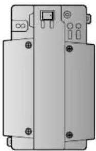
Pure electrical circuit lines without any symbolsDistributor (VL-VM701)*1
Thank you for purchasing a Panasonic product.
Please follow all instructions in this document and save it for future reference.
Carefully read the information found in the section titled "Important safety information" of the "Important Information" leaflet (supplied separately) in particular.
*1 In India, VL-VM701 is not sold and bus wiring is not available.
- The product is not compatible with HAC (Hearing Aid Compatibility).
This system is an auxiliary system; it is not designed to provide complete protection from property loss. Panasonic will not be held responsible in the event that property loss occurs while this system is in operation.
Note to the installer
- Please read this document carefully, and install the product safety and correctly by following the instructions.
- This document explains the following items.
– System configuration (star wiring and bus wiring)
– Wiring connections (star wiring and bus wiring)
– DIP switch settings (lobby station and distributor DIP switches)
How to get documentation
- For detailed information, such as lobby station components, included items, power supply unit connections, module assembly, and lobby station connections, download and refer to the Installation and Operating Instructions.
https://panasonic.net/cns/pcc/support/intercom/vl-vm
1.1 System configuration
1.1.1 Star wiring example
Example: 32 call buttons on the lobby station

flowchart
graph TD
    subgraph_Client_1["Client 1"]
        A1["#1"] --> B1["#2"]
        A2["#3"] --> B2["#4"]
        A3["#13"] --> B3["#14"]
        A4["#15"] --> B4["#16"]
    end
    subgraph_Client_2["Client 2"]
        B5["#18"] --> C5["#20"]
        B6["#29"] --> C6["#30"]
        B7["#31"] --> C7["#32"]
    end
    subgraph_Client_3["Client 3"]
        C8["#17"] --> D8["#18"]
        C9["#19"] --> D9["#20"]
    end
    subgraph_Client_4["Client 4"]
        D1["#4"] --> E1["Device"]
        D2["#2"] --> E2["Device"]
    end
    subgraph_Client_5["Client 5"]
        E3["#3"] --> F1["Device"]
        E4["#4"] --> F2["Device"]
    end
    subgraph_Client_6["Client 6"]
        F3["#5"] --> G1["Device"]
        F4["#6"] --> G2["Device"]
    end
    subgraph_Client_7["Client 7"]
        G5["#7"] --> H1["Device"]
        G6["#8"] --> H2["Device"]
    end
    subgraph_Client_8["Client 8"]
        H3["#9"] --> I1["Device"]
        H4["#10"] --> I2["Device"]
    end
    subgraph_Client_9["Client 9"]
        I3["#11"] --> J1["Device"]
        I4["#12"] --> J2["Device"]
    end
    subgraph_Client_10["Client 10"]
        J3["#13"] --> K1["Device"]
        J4["#14"] --> K2["Device"]
    end
    subgraph_Client_11["Client 11"]
        K5["#15"] --> L1["Device"]
        K6["#16"] --> L2["Device"]
    end
    subgraph_Client_12["Client 12"]
        L3["#17"] --> M1["Device"]
        L4["#18"] --> M2["Device"]
    end
1.1.2 Bus wiring example
Example 1: 16 call buttons on the lobby station
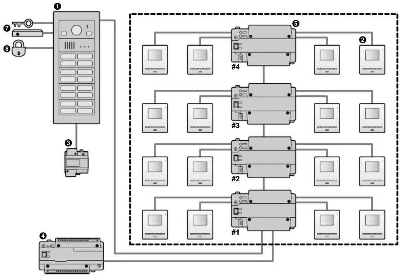
flowchart
graph TD
    A["①"] --> B["②"]
    A --> C["③"]
    A --> D["④"]
    B --> E["#1"]
    B --> F["#2"]
    B --> G["#3"]
    B --> H["#4"]
    C --> I["#1"]
    C --> J["#2"]
    C --> K["#3"]
    C --> L["#4"]
    D --> M["⑦"]
    D --> N["⑧"]
    style A fill:#f9f,stroke:#333
    style B fill:#ccf,stroke:#333
    style C fill:#cfc,stroke:#333
    style D fill:#fcc,stroke:#333
1.1.3 Bus wiring example
Example 2: 32 call buttons on the lobby station/6 lobby stations
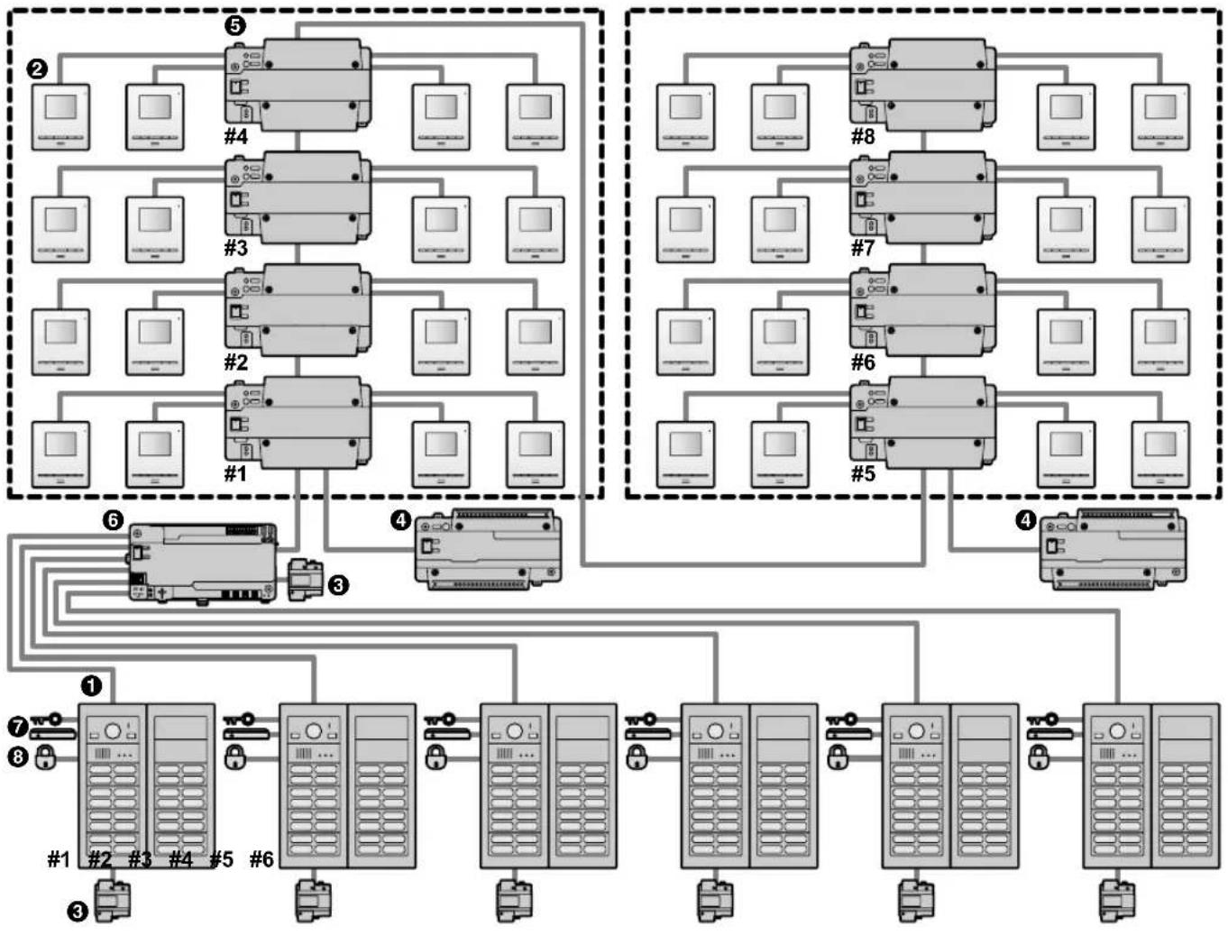
flowchart
graph TD
    subgraph Group1
        A1["Device ②"] --> B1["Device ③"]
        A2["Device ④"] --> B2["Device ⑤"]
        A3["Device ③"] --> B3["Device ④"]
        A4["Device ③"] --> B4["Device ⑤"]
        A5["Device ③"] --> B5["Device ④"]
        A6["Device ③"] --> B6["Device ⑤"]
        A7["Device ③"] --> B7["Device ④"]
        A8["Device ③"] --> B8["Device ⑤"]
        A9["Device ③"] --> B9["Device ⑥"]
    end

    subgraph Group2
        A10["Device ②"] --> B10["Device ③"]
        A11["Device ③"] --> B11["Device ⑤"]
        A12["Device ③"] --> B12["Device ④"]
        A13["Device ③"] --> B13["Device ⑤"]
        A14["Device ③"] --> B14["Device ④"]
        A15["Device ③"] --> B15["Device ⑤"]
        A16["Device ③"] --> B16["Device ④"]
        A17["Device ③"] --> B17["Device ⑤"]
        A18["Device ③"] --> B18["Device ④"]
        A19["Device ③"] --> B19["Device ⑤"]
    end

    subgraph Group3
        A20["Device ②"] --> B20["Device ③"]
        A21["Device ③"] --> B21["Device ⑤"]
        A22["Device ③"] --> B22["Device ④"]
        A23["Device ③"] --> B23["Device ⑤"]
        A24["Device ③"] --> B24["Device ④"]
        A25["Device ③"] --> B25["Device ⑤"]
        A26["Device ③"] --> B26["Device ④"]
        A27["Device ③"] --> B27["Device ⑤"]
        A28["Device ③"] --> B28["Device ④"]
        A29["Device ③"] --> B29["Device ⑤"]
    end

    subgraph Group4
        A30["Device ②"] --> B30["Device ③"]
        A31["Device ③"] --> B31["Device ⑤"]
        A32["Device ③"] --> B32["Device ④"]
        A33["Device ③"] --> B33["Device ⑤"]
        A34["Device ③"] --> B34["Device ④"]
        A35["Device ③"] --> B35["Device ⑤"]
        A36["Device ③"] --> B36["Device ④"]
        A37["Device ③"] --> B37["Device ⑤"]
    end

    subgraph Group5
        A38["Device ②"] --> B38["Device ③"]
        A39["Device ③"] --> B39["Device ⑤"]
        A40["Device ③"] --> B40["Device ④"]
        A41["Device ③"] --> B41["Device ⑤"]
        A42["Device ③"] --> B42["Device ④"]
        A43["Device ③"] --> B43["Device ⑤"]
        A44["Device ③"] --> B44["Device ④"]
        A45["Device ③"] --> B45["Device ⑤"]
    end

    subgraph Group6
        A46["Device ②"] --> B46["Device ③"]
        A47["Device ③"] --> B47["Device ⑤"]
        A48["Device ③"] --> B48["Device ④"]
        A49["Device ③"] --> B49["Device ⑤"]
    end

    subgraph Group7
        A49["Device ②"] --> B49["Device ③"]
        A50["Device ③"] --> B50["Device ⑤"]
        A51["Device ③"] --> B51["Device ④"]
        A52["Device ③"] --> B52["Device ⑤"]
    end

    subgraph Group8
        A53["Device ②"] --> B53["Device ③"]
        A54["Device ③"] --> B54["Device ⑤"]
        A55["Device ③"] --> B55["Device ④"]
        A56["Device ③"] --> B56["Device ⑤"]
    end
1.1.4 System devices
| No. Item Star wiring Bus wiring | |||
| 1 | Lobby station (VL-VM series) Up to 1 | Up to 6 | |
| 2 | Main monitor*1, *2 | Up to 32 (depending on the composition of the lobby station's modules) | |
| 3 | Power supply unit (VL-PS240) The | number of required power supply units differs depending on the number of devices used. | |
| 4 | Power supply unit (VL-PS2410) | The number of required power supply units differs depending on the number of devices used. | |
| 5 | Distributor (VL-VM701) – Up to 8 | ||
| 6 | Extension box (VL-V703) – Up to 1 | ||
| 7 | K-IN connection device (example: access controller and/or open door sensor, etc.) | Up to 2 Up to 2 | |
| 8 | Electric lock 1 per lobby station 1 per | lobby station | |
*1 Refer to the installation and power supply unit information in the Installation and Operating Instructions on the Panasonic Web site.
*2 VL-MV10 and VL-MWD501 support door bells. For VL-MWD501, a sound is played when the door bell is pressed, but "Doorphone unavailable" is displayed on the screen (this is normal).
2.1 Wiring Connections
2.1.1 Wiring schematics
Note:
- Refer to the power supply unit information in the Installation and Operating Instructions on the Panasonic Web site for information about connections for power supply units.
- See "3.1.1 Lobby station DIP switch settings" for information about lobby station DIP switch settings.
- See "3.1.2 Distributor DIP switch settings" for information about distributor DIP switches when using bus wiring.
- Insert the wires fully into the connection terminals. After inserting the wires, pull slightly on each wire to make sure it is firmly connected.
2.1.1.1 Star wiring example
Maximum number of devices
- Lobby station: up to 1
- Main monitor: up to 32 (depending on the composition of the lobby station's modules)
Important:
- When using star wiring, do not connect wires from main monitors to L1 and L2.
- Wiring is non-polarised.
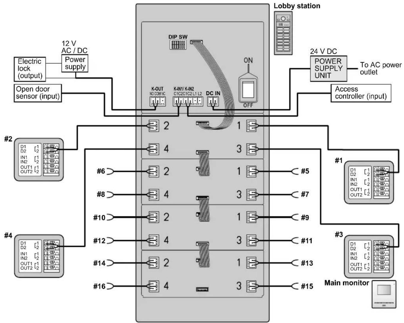
flowchart
graph TD
    A["Main monitor"] --> B["24 V DC POWER SUPPLY UNIT"]
    B --> C["To AC power outlet"]
    C --> D["Lobby station"]
    D --> E["12 V AC / DC Power supply"]
    E --> F["Open door sensor (input)"]
    F --> G["Electric lock (output)"]
    G --> H["DIP SW"]
    H --> I["K-OUT NC COM/VC"]
    H --> J["K-IN1/K-IN2 C1C2C1C2 L1 L2"]
    H --> K["DC IN"]
    K --> L["ON"]
    L --> M["OFF"]
    M --> N["Access controller (input)"]
    N --> O["#1"]
    O --> P["D1 D2 IN1 OUT1 OUT2"]
    O --> Q["#3"]
    Q --> R["D1 D2 IN1 OUT1 OUT2"]
    Q --> S["#15"]
    S --> T["#11"]
    T --> U["#13"]
    U --> V["#14"]
    V --> W["#16"]
    W --> X["#12"]
    X --> Y["#8"]
    Y --> Z["#6"]
    Z --> AA["#1"]
    AA --> AB["#5"]
    AB --> AC["#7"]
    AC --> AD["#9"]
    AD --> AE["#10"]
    AE --> AF["#12"]
    AF --> AG["#14"]
    AG --> AH["#16"]
2.1.1.2 Bus wiring examples
Maximum number of devices
- Lobby station: up to 6
- Main monitor: up to 32 (depending on the composition of the lobby station 's modules)
- Distributor: up to 8
- Extension box: up to 1 (required when expanding the lobby stations)
Using the distributor
Important:
- When using bus wiring, do not connect wires from main monitors to the terminals on the rear of the lobby station's button modules.
- Wiring is non-polarised.

flowchart
graph TD
    A["Electric lock (output)"] --> B["12 V AC / DC Power supply"]
    C["Open door sensor (input)"] --> B
    B --> D["Lobby station"]
    D --> E["24 V DC POWER SUPPLY UNIT"]
    E --> F["To AC power outlet"]
    D --> G["Access controller (input)"]
    H["From lobby station"] --> I["Distributor #1"]
    I --> J["Main monitor #1"]
    J --> K["#1"]
    J --> L["#2"]
    J --> M["#3"]
    J --> N["#4"]
    O["To 3rd distributor"] --> P["Distributor #2"]
    P --> Q["#5"]
    P --> R["#6"]
    P --> S["#7"]
    P --> T["#8"]
    U["24 V DC POWER SUPPLY UNIT*1"] --> V["To AC power outlet"]
    W["24 V DC Power supply unit"] --> X["Main monitor #1"]
    X --> Y["#1"]
    X --> Z["#2"]
    X --> AA["#3"]
    X --> AB["#4"]
*1 : From 24 V DC POWER SUPPLY UNIT
Using the extension box and distributor
Important:
- When using bus wiring, do not connect wires from main monitors to the terminals on the rear of the lobby station's button modules.
- When connecting to an extension box:
-Set all DIP switches of the extension box (VL-V703) to off.
-Do not connect wires to connectors 2 to 4 for the V700/VM701 on the extension box (VL-V703).
—Cannot monitor from the main monitor.
Set DIP switch "8" for the lobby station to the "on" position (prohibits monitoring).
See "3.1.1 Lobby station DIP switch settings".
- Wiring is non-polarised.
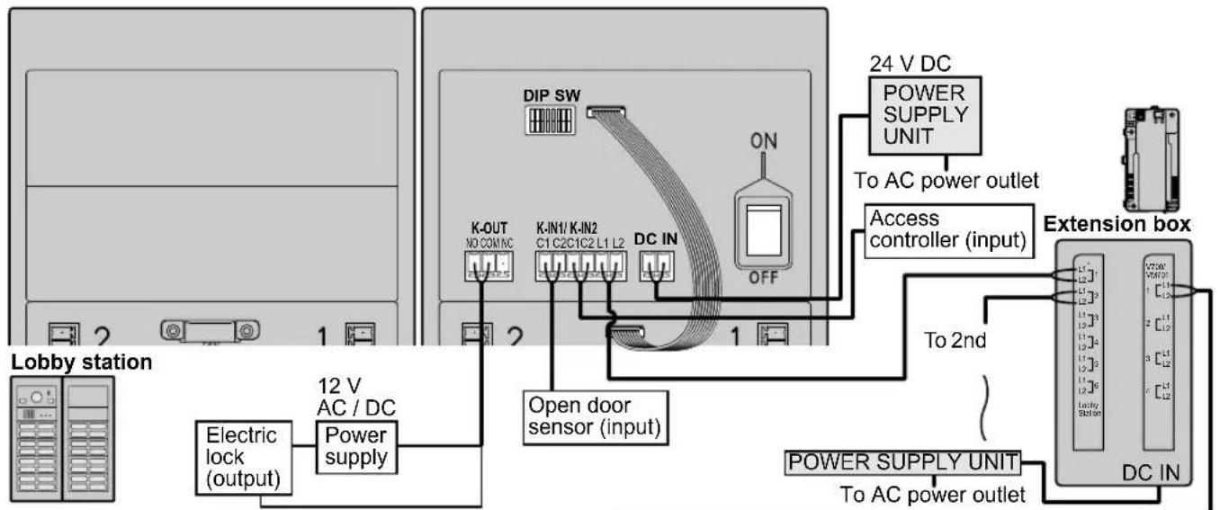
flowchart
graph TD
    A["Lobby station"] --> B["12 V AC / DC Power supply"]
    B --> C["Electric lock (output)"]
    C --> D["12 V AC / DC Power supply"]
    D --> E["Open door sensor (input)"]
    E --> F["DIP SW"]
    F --> G["24 V DC POWER SUPPLY UNIT"]
    G --> H["To AC power outlet"]
    H --> I["Access controller (input)"]
    I --> J["Extension box"]
    J --> K["TO AC power outlet"]
    K --> L["POWER SUPPLY UNIT"]
    L --> M["DC IN"]

flowchart
graph TD
    subgraph Top_Distributor
        A["To 3rd distributor"] --> B["Distributor #2"]
        B --> C["#5"]
        B --> D["#6"]
        B --> E["#7"]
        B --> F["#8"]
    end

    subgraph Middle_Distributor
        G["From extension box"] --> H["24 V DC POWER SUPPLY UNIT*1"]
        H --> I["To AC power outlet"]
    end

    subgraph Bottom_Distributor
        J["Main monitor #1"] --> K["#2"]
        J --> L["#3"]
        J --> M["#4"]
        J --> N["#5"]
        J --> O["#6"]
        J --> P["#7"]
        J --> Q["#8"]
    end

    A --> B
    H --> J
    B --> C
    B --> D
    B --> E
    B --> F
    B --> G
    B --> H
    B --> I
    B --> J
    B --> K
    B --> L
    B --> M
    B --> N
    B --> O
    B --> P
    B --> Q
    B --> R["Out1"]
    B --> S["OUT2"]
    style Top_Distributor fill:#f9f,stroke:#333
    style Middle_Distributor fill:#bbf,stroke:#333
    style Bottom_Distributor fill:#bfb,stroke:#333
*1 : From 24 V DC POWER SUPPLY UNIT
2.1.2 Wire type and maximum wire length
| Wiring run Wire diameter Max. length | |||||
| Star wiring | Lobby station | Main monitor | 0.65 mm (22 AWG) | approx. 100 m | |
| 1.2 mm (17 AWG) | approx. 200 m | ||||
| Power supply unit(VL-PS240) | Lobby station | 0.65 mm (22 AWG) | approx. 10 m | ||
| 2 mm (12 AWG) | approx. 20 m | ||||
| Power supply unit(VL-PS2410) | Lobby station | 0.65 mm (22 AWG) | approx. 50 m | ||
| 2 mm (12 AWG) | approx. 100 m | ||||
| Bus wiring | Lobby station | DistributorThe farthest distributor | 0.65 mm (22 AWG) | approx. 100 m | |
| 1.2 mm (17 AWG) | approx. 200 m | ||||
| Distributor*1 | Main monitor*2 | 0.65 mm (22 AWG) | approx. 100 m | ||
| 1.2 mm (17 AWG) | approx. 200 m | ||||
| Power supply unit(VL-PS240) | Lobby station | 0.65 mm (22 AWG) | approx. 10 m | ||
| 2 mm ( 12 AWG) | approx. 20 m | ||||
| Power supply unit(VL-PS2410) | Lobby station | 0.65 mm (22 AWG) | approx. 50 m | ||
| 2 mm (12 AWG) | approx. 100 m | ||||
| Power supply unit(VL-PS240)Power supply unit(VL-PS2410) | Distributor | 0.65 mm (22 AWG) | approx. 10 m | ||
| 2 mm (12 AWG) | approx. 20 m | ||||
| Power supply unit | AC power source | 1.2 mm (17 AWG) | No requirement | ||
| 2 mm (12 AWG) | |||||
| Lobby station | Electric lockK-IN connection device(example: access controller and/or open door sensor, etc.) | 0.5 mm (24 AWG) | according to specification of connected device. | ||
| 1.2 mm (17 AWG) | |||||
*1 Distributor connected to a power supply unit (when using VL-MV10 main monitors)
*2 The farthest main monitor (when using VL-MV10 main monitors)
Note the following when selecting wiring
- Use 2-conductor (solid copper) wiring with a PE (polyethylene)-insulated PVC jacket. Mid-capacitance, non-shielded cable is recommended.
- A certified power supply wiring has to be used with this equipment. The relevant national installation and/or equipment regulations shall be considered. A certified power supply wiring not lighter than ordinary polyvinyl chloride flexible wiring according to IEC 60227 shall be used.
- When an extension box is connected, the maximum wire length from the lobby station to the distributor does not change.
3.1 DIP switch settings
3.1.1 Lobby station DIP switch settings
The following lobby station DIP switch settings are required when installing the lobby station.

| Item Setting | DIP switch Item | Setting DIP switch | |||
| Wiring method | Star wiring | ONOFF 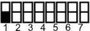 | Audio guidance language (when unlocking a door) | No audio guidance | ONOFF  |
| Bus wiring | ONOFF  | English | ONOFF 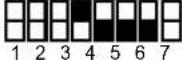 | ||
| Backlighting for call buttons in standby mode | Turns on in dark condition | ONOFF  | German | ONOFF 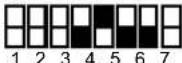 | |
| Always on | ONOFF  | French | ONOFF  | ||
| Always off | ONOFF  | Spanish | ONOFF  | ||
| Prohibit monitoring from a main monitor● When using a VL-V703 (extension box), set DIP switch "8" to the "on" position (prohibits monitoring). | ONOFF  | Italian | ONOFF  | ||
| Allow monitoring from a main monitor | ONOFF  | Dutch | ONOFF  | ||
| Arabic | ONOFF  | ||||
| Persian | ONOFF 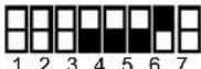 | ||||
3.1.2 Distributor DIP switch settings
The following DIP switch settings are required when installing the distributor using bus wiring.
- Distributor ID settings #1 – #8: applicable DIP switches (①) must be configured at each distributor.
- Room number ID settings ① – ③2: applicable DIP switches (②) must be configured according to each button number of the lobby stations and rooms.
A: For the purpose of an explanation, numbers are written on the name plates of each call button of the lobby stations.
Example: When configuring room number 20, set the DIP switch of the applicable distributors ⑳.

flowchart
graph TD
    subgraph_Server_A["Server"]
        A1["1"] -->|2| B1["2"]
        A2["3"] -->|2| B2["2"]
        A3["4"] -->|2| B3["2"]
        A4["5"] -->|2| B4["2"]
        A5["6"] -->|2| B5["2"]
        A6["7"] -->|2| B6["2"]
        A7["8"] -->|2| B7["2"]
        A8["9"] -->|2| B8["2"]
        A9["10"] -->|2| B9["2"]
        A10["11"] -->|2| B10["2"]
        A11["12"] -->|2| B11["2"]
        A12["13"] -->|2| B12["2"]
        A13["14"] -->|2| B13["2"]
        A14["15"] -->|2| B14["2"]
        A15["16"] -->|2| B15["2"]
        A16["17"] -->|2| B16["2"]
        A17["18"] -->|2| B17["2"]
        A18["19"] -->|2| B18["2"]
        A19["20"] -->|2| B19["2"]
        A20["21"] -->|2| B20["2"]
        A21["22"] -->|2| B21["2"]
        A22["23"] -->|2| B22["2"]
        A23["24"] -->|2| B23["2"]
        A24["25"] -->|2| B24["2"]
        A25["26"] -->|2| B25["2"]
        A26["27"] -->|2| B26["2"]
        A27["28"] -->|2| B27["2"]
        A28["29"] -->|2| B28["2"]
        A29["30"] -->|2| B29["2"]
        A30["31"] -->|2| B30["2"]
        A31["32"] -->|2| B31["2"]
        A32["33"] -->|2| B32["2"]
        A33["34"] -->|2| B33["2"]
        A34["35"] -->|2| B34["2"]
        A35["36"] -->|2| B35["2"]
        A36["37"] -->|2| B36["2"]
        A37["38"] -->|2| B37["2"]
        A38["39"] -->|2| B38["2"]
        A39["40"] -->|2| B39["2"]
        A40["41"] -->|2| B40["2"]
        A41["42"] -->|2| B41["2"]
        A42["43"] -->|2| B42["2"]
        A43["44"] -->|2| B43["2"]
        A44["45"] -->|2| B44["2"]
        A45["46"] -->|2| B45["2"]
        A46["47"] -->|2| B46["2"]
        A47["48"] -->|2| B47["2"]
        A48["49"] -->|2| B48["2"]
        A49["50"] -->|2| B49["2"]
        A50["51"] -->|2| B50["2"]
        A51["52"] -->|2| B51["2"]
        A52["53"] -->|2| B52["2"]
        A53["54"] -->|2| B53["2"]
        A54["55"] -->|2| B54["2"]
        A55["56"] -->|2| B55["2"]
        A56["57"] -->|2| B56["2"]
        A57["58"] -->|2| B57["2"]
        A58["59"] -->|2| B58["2"]
        A59["60"] -->|2| B59["2"]
    end
    subgraph Server_B
        B1_1((BIP SWITCH ON))
        B1_1_1((ON))
    end
    subgraph Server_B_A
        Server_A_1["A"]
    end
    subgraph Server_B_1_1
            B1_1_1_1
            B1_1_1_1
            B1_1_1_1
            B1_1_1_1
            B1_1_1_1
            B1_1_1_1
            B1_1_1_1
            B1_1_1_1
            B1_1_1_1
            B1_1_1_1
            B1_3(ON)
            B1_3(ON)
            B1_3(ON)
            B1_3(ON)
            B1_3(ON)
            B1_3(ON)
            B1_3(ON)
            B1_3(ON)
            B1_3(ON)
            B1_3(ON)
            B1_3(ON)
            B1_3(ON)
            B1_3(ON)
            B1  (ON)
            B1  (ON)
            B1  (ON)
            B1  (ON)
            B1  (ON)
            B1  (ON)
            B1  (ON)
            B1  (ON)
            B1  (ON)
            B1  (ON)
            B1  (ON)
            B1  (ON)
            B1  (ON)
            B1  (ON)
            B1  (ON)
3.1.2.1 Distributor ID settings ①
 |
3.1.2.2 Room number ID settings ②
| Setting DIP switch Setting DIP switch | |||
| Button 1 | 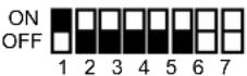 | Button 17 |  |
| Button 2 |  | Button 18 | 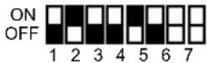 |
| Button 3 | 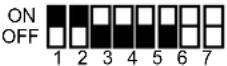 | Button 19 | 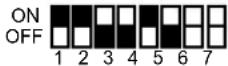 |
| Button 4 |  | Button 20 | 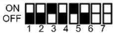 |
| Button 5 |  | Button 21 |  |
| Button 6 |  | Button 22 |  |
| Button 7 |  | Button 23 | 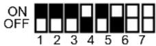 |
| Button 8 |  | Button 24 |  |
| Button 9 |  | Button 25 |  |
| Button 10 | 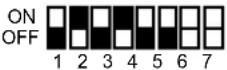 | Button 26 |  |
| Button 11 |  | Button 27 | 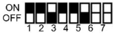 |
| Button 12 |  | Button 28 | 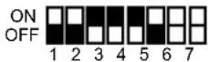 |
| Button 13 | 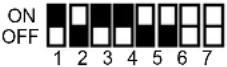 | Button 29 |  |
| Button 14 |  | Button 30 |  |
| Button 15 |  | Button 31 |  |
| Button 16 |  | Button 32 |  |
Panasonic Corporation
1006, Oaza Kadoma, Kadoma-shi, Osaka 571-8501, Japan
http://www.panasonic.com
© Panasonic Corporation 2018
- Video Intercom System — Lobby station/Distributor
- Model No. VL-VM series / VL-VM701
- Note to the installer
- How to get documentation
- System configuration
- Star wiring example
- Bus wiring example
- Bus wiring example
- System devices
- Wiring Connections
- Wiring schematics
- Note:
- Star wiring example
- Maximum number of devices
- Important:
- Bus wiring examples
- Using the distributor
- Note the following when selecting wiring
- DIP switch settings
- Lobby station DIP switch settings
- Distributor DIP switch settings
- Panasonic Corporation
Brand : PANASONIC
Model : VL-VM902EX
Category : Doorbell