
SuperChassis 512L-260-LCD - Computer case Supermicro - Free user manual and instructions
Find the device manual for free SuperChassis 512L-260-LCD Supermicro in PDF.


| Product Type | 1U Rackmount Server Chassis |
| Brand | Supermicro |
| Model | SuperChassis 512L-260-LCD |
| Form Factor | 1U |
| CPU Support | Single Processor (UP) - Supports Xeon, Pentium D, P3/P4 |
| I/O Expansion Slots | 1 Full-Height, Full-Length PCI |
| Drive Bays | 1x Fixed 3.5" SATA Hard Drive |
| Power Supply | 260W High-Efficiency, Auto-Switching (100-240V) |
| Cooling | Internal Blower Unit |
| Control Panel | LCD Display, Power Button, Reset Button, 5 Status LEDs (Overheat/Fan Fail, NIC2, NIC1, HDD, Power) |
| Dimensions (Approx.) | 1.75" H x 17.2" W x 25.6" D (44mm x 437mm x 650mm) |
| Weight (Approx.) | 18 lbs (8.2 kg) |
| Color | Black |
| Material | Steel Chassis |
| Rack Mounting | Included Rail Kit; Supports Mid-Mount Telco Rack |
| Included Accessories | Rack Rails, Screws, Power Cord, I/O Shield, Standoffs |
| Maintenance | Tool-less Fan/Blower Replacement, Easy Access Power Supply |
| Safety Features | ESD Protection (Antistatic Bags), Grounded Outlet Required |
| Spare Parts Availability | Power Supply, Blower, LED Panel, Rails - Available from Supermicro |
| Compliance | UL, CE, FCC (estimated) |
Frequently Asked Questions - SuperChassis 512L-260-LCD Supermicro
User questions about SuperChassis 512L-260-LCD Supermicro
0 question about this device. Answer the ones you know or ask your own.
Ask a new question about this device
Download the instructions for your Computer case in PDF format for free! Find your manual SuperChassis 512L-260-LCD - Supermicro and take your electronic device back in hand. On this page are published all the documents necessary for the use of your device. SuperChassis 512L-260-LCD by Supermicro.
USER MANUAL SuperChassis 512L-260-LCD Supermicro
SC512 Chassis Series

SC512-260B
SC512-200B

SC512F-600B

SC512F-260(B)

SC512F-520(B)
SC512F-410(B)

SC512L-260(B)
SC512L-200B

SC512F-600LB
SC512F-520L(B)

SC512L-260(B)-LCD

SC512F-350B

SC512C-260(B)
SC512C-200(B)

SC512F-280(B)
USER'S MANUAL
The information in this User's Manual has been carefully reviewed and is believed to be accurate. The vendor assumes no responsibility for any inaccuracies that may be contained in this document, makes no commitment to update or to keep current the information in this manual, or to notify any person or organization of the updates. Please Note: For the most up-to-date version of this manual, please see our web site at www.supermicro.com.
Super Micro Computer, Inc. ("Supermicro") reserves the right to make changes to the product described in this manual at any time and without notice. This product, including software and documentation, is the property of Supermicro and/or its licensors, and is supplied only under a license. Any use or reproduction of this product is not allowed, except as expressly permitted by the terms of said license.
IN NO EVENT WILL SUPERMICRO BE LIABLE FOR DIRECT, INDIRECT, SPECIAL, INCIDENTAL, SPECULATIVE OR CONSEQUENTIAL DAMAGES ARISING FROM THE USE OR INABILITY TO USE THIS PRODUCT OR DOCUMENTATION, EVEN IF ADVISED OF THE POSSIBILITY OF SUCH DAMAGES. IN PARTICULAR, SUPERMICRO SHALL NOT HAVE LIABILITY FOR ANY HARDWARE, SOFTWARE, OR DATA STORED OR USED WITH THE PRODUCT, INCLUDING THE COSTS OF REPAIRING, REPLACING, INTEGRATING, INSTALLING OR RECOVERING SUCH HARDWARE, SOFTWARE, OR DATA.
Any disputes arising between manufacturer and customer shall be governed by the laws of Santa Clara County in the State of California, USA. The State of California, County of Santa Clara shall be the exclusive venue for the resolution of any such disputes. Super Micro's total liability for all claims will not exceed the price paid for the hardware product.
California Best Management Practices Regulations for Perchlorate Materials: This Perchlorate warning applies only to products containing CR (Manganese Dioxide) Lithium coin cells. "Perchlorate Material-special handling may apply. See www.dtsc.ca.gov/hazardouswaste/perchlorate"
WARNING: Handling of lead solder materials used in this product may expose you to lead, a chemical known to the State of California to cause birth defects and other reproductive harm.
Manual Revision 1.0c
Release Date: November 2, 2010
Unless you request and receive written permission from Super Micro Computer, Inc., you may not copy any part of this document.
Information in this document is subject to change without notice. Other products and companies referred to herein are trademarks or registered trademarks of their respective companies or mark holders.
Copyright © 2010 by Super Micro Computer, Inc.
All rights reserved.
Printed in the United States of America
Preface
About This Manual
This manual is written for professional system integrators and PC technicians. It provides information for the installation and use of the SC512 1U chassis. Installation and maintenance should be performed by experienced technicians only.
Supermicro's SC512 1U chassis features a unique and highly-optimized design for dual-core Xeon platforms. The chassis is equipped with a 200, 260, 280. 350, 410, 520 or 600 Watt high-efficiency power supply for superb power savings. High-performance fans provide ample optimized cooling for FB-DIMM memory modules in a 1U form factor.
This document lists compatible parts available when this document was published. Always refer to the our Web site for updates on supported parts and configurations.
Manual Organization
Chapter 1: Introduction
The first chapter provides a checklist of the main components included with this chassis and describes the main features. This chapter also includes contact information.
Chapter 2: System Safety
This chapter lists warnings, precautions, and system safety. You should thoroughly familiarize yourself with this chapter for a general overview of safety precautions that should be followed before installing and servicing this chassis.
Chapter 3: Chassis Components
Refer to this chapter for details on this chassis model including the fans, bays, airflow shields, and other components.
Chapter 4: System Interface
Refer to this chapter for details on the system interface, which includes the functions and information provided by the control panel on the chassis as well as other LEDs located throughout the system.
Chapter 5: Chassis Setup and Maintenance
Follow the procedures given in this chapter when installing, removing, or reconfiguring your chassis.
Chapter 6: Rack Installation
Refer to this chapter for detailed information on chassis rack installation. You should follow the procedures given in this chapter when installing, removing or reconfiguring your chassis into a rack environment.
Appendix A Cables, Screws, and Other Accessories Appendix B Power Supply Specifications
Table of Contents
About This Manual .... iii
Manual Organization ....iv
Chapter 1 Introduction
1-1 Overview 1-1
1-2 Chassis Features 1-2
CPU 1-2
I/O Expansion slots 1-2
Peripheral Drives 1-2
Dual Hard Drives 1-2
1-3 Contacting Supermicro 1-3
1-4 Returning Merchandise for Service.... 1-4
Chapter 2 System Safety
2-1 Overview 2-1
2-2 Warnings and Precautions 2-1
2-3 Preparing for Setup 2-1
2-4 Electrical Safety Precautions 2-1
2-5 General Safety Precautions 2-3
2-6 System Safety 2-3
Chapter 3 Chassis Components
3-1 Overview 3-1
3-2 Components 3-1
Chassis 3-1
Fans 3-1
Blower 3-1
Mounting Rails 3-1
Power Supply 3-2
Air Shroud 3-2
3-3 Where to get Replacement Components.... 3-2
3-4 Chassis Model Options 3-2
Identifying Fan and Blower-Cooled Chassis Models 3-2
Model SC512 3-4
Model SC512C 3-5
Model SC512F 3-6
Model SC512L 3-9
Chapter 4 System Interface
4-1 Overview 4-1
4-2 Control Panel Buttons 4-2
4-3 Control Panel LEDs 4-2
Chapter 5 Chassis Setup and Maintenance
5-1 Overview 5-1
5-2 Installation Procedures .... 5-1
General Maintenance .... 5-1
5-3 Removing the Chassis Cover 5-2
5-4 Installing Hard Drives....5-3
5-5 Installing the Motherboard .... 5-5
Important Motherboard Installation Information .... 5-5
Standoffs .... 5-6
5-6 Installing the DVD or CD-ROM Drive .... 5-7
PCI Slot Setup .... 5-8
5-7 Installing the Air Shroud....5-9
Installation Complete....5-10
5-8 System Fans/Blower ....5-11
System Fan Tray ....5-11
System Fan Tray Replacement.... 5-12
Blower Setup .... 5-13
5-9 Power Supply .... 5-15
Power Supply Failure .... 5-15
Replacing the Chassis LED Panel .... 5-17
Chapter 6 Rack Installation
6-1 Overview 6-1
6-2 Unpacking the System 6-1
6-3 Preparing for Setup 6-1 Choosing a Setup Location 6-1
Rack Precautions 6-2
General Server Precautions 6-2
Rack Mounting Considerations 6-3
Ambient Operating Temperature 6-3
Reduced Airflow 6-3
Mechanical Loading 6-3
Circuit Overloading 6-3
Reliable Ground 6-3
6-4 Rack Mounting Instructions 6-4
Identifying the Sections of the Rack Rails (Optional Item) 6-4
Installing the Inner Rail Extension 6-5
Installing the Outer Rails to the Rack 6-6
Installing the Chassis into a Rack.... 6-8
Mid-Mount Telco Rack.... 6-9
Installing the Chassis into a Rack in Mid-Mount Position 6-9
Appendix A Cables, Screws, and Other Accessories
Appendix B Power Supply Specifications
Notes
Chapter 1
Introduction
1-1 Overview
Supermicro's SC512 1U chassis features a unique and highly-optimized design. The chassis is equipped with a high-efficiency power supply in a small form factor for optimized space efficiency.
The following chart lists model numbers and features currently available at the time of printing. For additional information visit the Supermicro Web site at www.supermicro.com
| SC512 Chassis | ||||
| Model CPU HDD I/O Slots Power Supply | ||||
| SC512-200B | UP 1x Fixed 3.5" FH | 200W (High-Efficiency) | ||
| SC512-260B | UP 1x Fixed 3.5" FH 260W | |||
| SC512C-200(B) | UP 1x Fixed 3.5" FH 200W | |||
| SC512C-260(B) | UP 1x Fixed 3.5" FH 260W | |||
| SC512F-260(B) | UP 1x Fixed 3.5" FH 260W | |||
| SC512L-200B | UP 2x Fixed 3.5" FH 200W | |||
| SC512L-260(B) | UP 2x Fixed 3.5" FH 260W | |||
| SC512L-260(B)-LCD | UP 1x Fixed 3.5" FH 260W | |||
| SC512F-280(B) | DP/UP 2x Fixed 3.5" FH 280W (High-Efficiency) | |||
| SC512F-350B | DP/UP 2x Fixed 3.5" FH 350W (Gold Level) | |||
| SC512F-410(B) | DP/UP 1x Fixed 3.5" FH 410W DC | |||
| SC512F-520(B) | DP/UP 1x Fixed 3.5" FH 520W (High-Efficiency) | |||
| SC512F-600B | DP/UP 1x Fixed 3.5" FH 600W (Gold Level) | |||
| SC512F-520L(B) | DP/UP 1x Fixed 3.5" FH 520W (High-Efficiency) | |||
| SC512F-600LB | DP/UP 1x Fixed 3.5" FH 600W (Gold Level) | |||
Legend:
$$ D P = \text { Dual Processor Support } $$
$$ \mathrm{UP} = \text { Single Processor Support } $$
$$ F F = \text { Full - height }, \text { Full - length } $$
$$ F H = \text { Full - height, Half - length } $$
$$ \mathrm{LP} = \text { L o w - p r o f i l e } $$
1-2 Chassis Features
The SC512 1U high-performance chassis supports a wide range of features. See the Chassis Components section of this manual for a list of features included in each of the SC512 models.
CPU
The SC512 chassis supports a DP and/or UP Xeon, Pentium D, P3/P4 processors. Please refer to the motherboard specifications pages on our web site for updates on supported processors.
I/O Expansion slots
Each version of the SC512 chassis includes one full I/O expansion slot
Peripheral Drives
Some SC512 chassis support peripheral dives such as a DVD-ROM, CD-ROM or floppy disk drive. These drives allow data to be installed or saved quickly.
Dual Hard Drives
Some SC512 chassis models support a second hard disk drive. For more details, check the Chassis Components section of this manual or the Supermicro Website at www.supermicro.com.
1-3 Contacting Supermicro
Headquarters
Address: Super Micro Computer, Inc.
980 Rock Ave.
San Jose, CA 95131 U.S.A.
Tel: +1 (408) 503-8000
Fax: +1 (408) 503-8008
Email: marketing@supermicro.com (General Information)
support@supermicro.com (Technical Support)
Web Site: www.supermicro.com
Europe
Address: Super Micro Computer B.V.
's-Hertogenbosch, The Netherlands
Tel: +31 (0) 73-6400390
Fax: +31 (0) 73-6416525
Email: sales@supermicro.nl (General Information)
support@supermicro.nl (Technical Support)
rma@supermicro.nl (Customer Support)
Asia-Pacific
Address: Super Micro Computer, Inc.
4F, No. 232-1, Liancheng Rd.
Chung-Ho 235, Taipei County
Taiwan, R.O.C.
Tel: +886-(2) 8226-3990
Fax: +886-(2) 8226-3991
Web Site: www.supermicro.com.tw
Technical Support:
Email: support@supermicro.com.tw
Tel: 886-2-8226-1900
1-4 Returning Merchandise for Service
A receipt or copy of your invoice marked with the date of purchase is required before any warranty service will be rendered. You can obtain service by calling your vendor for a Returned Merchandise Authorization (RMA) number. When returning to the manufacturer, the RMA number should be prominently displayed on the outside of the shipping carton, and mailed prepaid or hand-carried. Shipping and handling charges will be applied for all orders that must be mailed when service is complete.
For faster service, RMA authorizations may be requested online (http://www.supermicro.com/support/rma/).
Whenever possible, repack the chassis in the original Supermicro carton, using the original packaging material. If these are no longer available, be sure to pack the chassis securely, using packaging material to surround the chassis so that it does not shift within the carton and become damaged during shipping.
This warranty only covers normal consumer use and does not cover damages incurred in shipping or from failure due to the alteration, misuse, abuse or improper maintenance of products.
During the warranty period, contact your distributor first for any product problems.
Chapter 2
System Safety
2-1 Overview
This chapter provides a quick setup checklist to get your chassis up and running. Following the steps in order given should enable you to have your chassis setup and operational within a minimal amount of time. This quick setup assumes that you are an experienced technician, familiar with common concepts and terminology.
2-2 Warnings and Precautions
You should inspect the box the chassis was shipped in and note if it was damaged in any way. If the chassis itself shows damage, file a damage claim with carrier who delivered your system.
Decide on a suitable location for the rack unit that will hold that chassis. It should be situated in a clean, dust-free area that is well ventilated. Avoid areas where heat, electrical noise and eletromagnetic fields are generated.
You will also need it placed near at least one grounded power outlet. When configured, the SC512 chassis includes one power supply.
2-3 Preparing for Setup
The SC512 chassis includes a set of rail assemblies, including mounting brackets and mounting screws you will need to install the systems into the rack. Please read this manual in its entirety before you begin the installation procedure.
2-4 Electrical Safety Precautions
Basic electrical safety precautions should be followed to protect yourself from harm and the SC512 from damage:
- Be aware of the locations of the power on/off switch on the chassis as well as the room's emergency power-off switch, disconnection switch or electrical outlet. If an electrical accident occurs, you can then quickly remove power from the system.
Do not work alone when working with high-voltage components.
- Power should always be disconnected from the system when removing or installing main system components, such as the serverboard, memory modules and the DVD-ROM and peripheral drives (not necessary for hot-swappable drives). When disconnecting power, you should first power down the system with the operating system and then unplug the power cords from all the power supply modules in the system.
- When working around exposed electrical circuits, another person who is familiar with the power-off controls should be nearby to switch off the power, if necessary.
Use only one hand when working with powered-on electrical equipment. This is to avoid making a complete circuit, which will cause electrical shock. Use extreme caution when using metal tools, which can easily damage any electrical components or circuit boards they come into contact with.
Do not use mats designed to decrease electrostatic discharge as protection from electrical shock. Instead, use rubber mats that have been specifically designed as electrical insulators.
The power cord must include a grounding plug and must be plugged into a grounded electrical outlet.
Serverboard battery: CAUTION - There is a danger of explosion if the onboard ● battery is installed upside down, which will reverse its polarities This battery must be replaced only with the same or an equivalent type recommended by the manufacturer. Dispose of used batteries according to the manufacturer's instructions.
- DVD-ROM laser: CAUTION - This server may have come equipped with a DVD-ROM drive. To prevent direct exposure to the laser beam and hazardous radiation exposure, do not open the enclosure or use the unit in any unconventional way.
2-5 General Safety Precautions
Keep the area around the chassis clean and free of clutter.
- Place the chassis top cover and any system components that have been removed away from the system or on a table so that they won't accidentally be stepped on.
While working on the system, do not wear loose clothing such as neckties and unbuttoned shirt sleeves, which can come into contact with electrical circuits or be pulled into a cooling fan.
Remove any jewelry or metal objects from your body, which are excellent metal conductors that can create short circuits and harm you if they come into contact with printed circuit boards or areas where power is present.
After accessing the inside of the system, close the system back up and secure it to the rack unit with the retention screws after ensuring that all connections have been made.
2-6 System Safety
Electrostatic discharge (ESD) is generated by two objects with different electrical charges coming into contact with each other. An electrical discharge is created to neutralize this difference, which can damage electronic components and printed circuit boards. The following measures are generally sufficient to neutralize this difference before contact is made to protect your equipment from ESD:
Do not use mats designed to decrease electrostatic discharge as protection from electrical shock. Instead, use rubber mats that have been specifically designed as electrical insulators.
Use a grounded wrist strap designed to prevent static discharge.
Keep all components and printed circuit boards (PCBs) in their antistatic bags • until ready for use.
Touch a grounded metal object before removing any board from its antistatic bag.
Do not let components or PCBs come into contact with your clothing, which may retain a charge even if you are wearing a wrist strap.
Handle a board by its edges only; do not touch its components, peripheral chips, memory modules or contacts.
When handling chips or modules, avoid touching their pins.
- Put the serverboard and peripherals back into their antistatic bags when not in use.
For grounding purposes, make sure your computer chassis provides excellent conductivity between the power supply, the case, the mounting fasteners and the serverboard.
Chapter 3
Chassis Components
3-1 Overview
This chapter describes the most common components included with your chassis. Some components listed may not be included or compatible with your particular chassis model. For more information, see the installation instructions detailed later in this manual.
3-2 Components
Chassis
Depending on the model, the SC512 chassis may include one slim DVD-ROM/CD-ROM bay, at least one fixed hard drive, a floppy drive, and/or two USB ports. For the latest shipping lists, visit our Web site at: http://www.supermicro.com.
Fans
The SC512 model chassis accepts two or three system fans powered by the motherboard. These fans are 1U high and are powered by 4-pin connectors.
Blower
The SC512, SC512L and SC512C model chassis use a single blower unit for system cooling.
Mounting Rails
The SC512 can be placed in a rack for secure storage and use. To set up your rack, follow the step-by-step instructions included in this manual. SC512 models with narrow chassis designs include specialized rails for mounting in a standard rack. See the Rack Installation section of this manual for details.
Power Supply
Each SC512 chassis model includes a high-efficiency power supply rated at 200, 260, 280, 350, 410 or 580 Watts. In the unlikely event your power supply fails, replacement is simple and can be done without tools.
Air Shroud
Air shrouds are shields, usually plastic, that funnel air directly to where it is needed. Always use the air shroud included with your chassis.
3-3 Where to get Replacement Components
Though not frequently, you may need replacement parts for your system. To ensure the highest level of professional service and technical support, we strongly recommend purchasing exclusively from our Supermicro Authorized Distributors/System Integrators/Resellers. A list of Supermicro Authorized Distributors/System Integrators/Reseller can be found at: http://www.supermicro.com. Click the Where to Buy link.
3-4 Chassis Model Options
The following section lists the different options which are available for each of the different chassis models in the SC512 chassis family of products.
Identifying Fan and Blower-Cooled Chassis Models
Your SC512 chassis is equipped with either a blower unit or a set of system fans for optimized chassis cooling.
The SC512, SC512C and most SC512L model chassis use a blower unit for chassis cooling.
The SC512F model chassis are cooled with system fans. The number of system fans included in your specific system may vary.
See the following page for illustrations of blower units and system fans. For detailed instructions on replacing a blower unit or system fans, see the Chassis Setup and Maintenance section of this manual.

Figure 3-1: Blower-Cooled Chassis Model

Figure 3-2: Fan-Cooled Chassis Model
Model SC512
Includes a slot with a dummy cover plate where an optional DVD-ROM drive may be installed, and a 200 or 260 Watt power supply. The SC512 model chassis is cooled with an internal blower unit.

Figure 3-3: Chassis Model SC512-200, SC512-260
| SC512-200 | ||||||||
| Chassis | Blower/ Fan | DVD/CD | Floppy US$B CPU | I/O | Slots | HDD | Power Supply | |
| Standard | Blower Optional DVD | - 2x | USB | UP F | H 1x | Fixed 3.5" | 200 Watt High-Efficiency | |
| SC512-260 | ||||||||
| Chassis | Blower/ Fan | DVD/CD | Floppy US$B CPU | I/O | Slots | HDD Power Supply | ||
| Standard | Blower Optional DVD | - 2x | USB | UP FH 1x | Fixed 3.5" | 260 Watt | ||
Model SC512C
The SC512C includes a DVD-ROM drive, floppy drive, USB ports and a 200 or 260 Watt power supply. The SC512C model chassis is cooled with an internal blower unit.

Figure 3-4: Chassis Model SC512C
| SC512C-200 | ||||||||
| Chassis B | lower/ Fan | DVD/CD | Floppy USB | B CPU | I/O | Slots | HDD Power Supply | |
| Standard B | lower DVD | 1x | Floppy | 2x USB | UP F | H 1x | Fixed 3.5" | 200 Watt |
| SC512C-260 | ||||||||
| Chassis | Blower/ Fan | DVD/ CD | Floppy | USB CPU | I/O | Slots | HDD Power Supply | |
| Standard | Blower D | VD | 1x Floppy | 2x USB | UP | FH | 1x Fixed 3.5" | 260 Watt |
Model SC512F
The SC512F models may include a DVD-ROM drive, USB ports and a 260, 280, 350, 410, 520 or 600 Watt power supply. The SC512F-280 and 350 models can support a second optional hard disk drive. The SC512F-280/350/410/520/600 model chassis have a wider chassis design, which mounts in a standard rack utilizing special mounting rails. See the Rack Installation section of this manual for details. All SC512F model chassis are cooled with system fans.

Figure 3-5: Chassis Model SC512F-260
| SC512F-260 | ||||||||
| Chassis B | Blower/ Fan | DVD/CD | Floppy USB | B CPU | I/O | Slots | HDD Power Supply | |
| Narrow* | 2x Fan | 1x DVD - | 2x | USB | UP FH | 1x | Fixed 3.5" | 260 Watt |
* Note: Narrow chassis models include specialized mounting rails to fit into a standard rack. See the Rack Installation section of this manual for details.

Figure 3-6: Chassis Model SC512F-280
| SC512F-280 | ||||||||
| Chassis | Blower/ Fan | DVD/CD | Floppy USB | CPU | I/O | Slots | HDD | Power Supply |
| Standard | 2x Fan 1x | DVD -- DP/ | UP | FH 2x | Fixed 3.5" | 280 Watt High-Efficiency | ||

Figure 3-7: Chassis Model SC512F-350
| SC512F-350 | ||||||||
| Chassis | Blower/ Fan | DVD/CD | Floppy USB | CPU | I/O | Slots | HDD Power Supply | |
| Standard | 2x Fan Optiional DVD | -- DP/ | UP | FH | 2x Fixed 3.5" | 350 Watt Gold-Level | ||

Figure 3-8: Chassis Models SC512F-410 and SC512F-520
| SC512F-520 | ||||||||
| Chassis | Blower/ Fan | DVD/CD | Floppy US | B CPU | I/O | Slots | HDD | Power Supply |
| Standard | 3x Fans 1x | DVD - 2x | USB | DP/ UP | FH 1x | Fixed 3.5" | 520 Watt High-Efficiency | |
| SC512F-410 | ||||||||
| Chassis | Blower/ Fan | DVD/ CD | Floppy | USB CPU | I/O | Slots | HDD Power Supply | |
| Standard | 3x Fans 1x | DVD - 2x | USB | DP/ UP | FH 1x | Fixed 3.5" | 410 DC | |

Figure 3-9: Chassis Model SC512F-600
| SC512F-600 | ||||||||
| Chassis | Blower/ Fan | DVD/ CD | Floppy | USB CPU | I/O | Slots | HDD Power Supply | |
| Standard | 3x Fan | Optional DVD | - 2x | USB | DP/ UP | FH 1x | Fixed 3.5" | 600 Watt Gold Level |

Figure 3-10: Chassis Models SC512F-520L and SC512F-600L
| SC512F-520L | ||||||||
| Chassis | Blower/ Fan | DVD/CD | Floppy US | B CPU | I/O | Slots | HDD | Power Supply |
| Standard | 3x Fans -- | - DP/ | UP | FH 1x | Fixed 3.5" | 520 Watt High Efficiency | ||
| SC512F-600L | ||||||||
| Chassis | Blower/ Fan | DVD/CD | Floppy US | B CPU | I/O | Slots | HDD | Power Supply |
| Standard | 3x Fans -- | - DP/ | UP | FH 1x | Fixed 3.5" | 600 Watt Gold Level | ||
Model SC512L
The SC512L models include two 3.5" hard disk drives and a 200 or 260 Watt power supply. The SC512L model chassis is cooled with an internal blower unit.

natural_image
Front panel of a server rack with ports and indicator lights (no text or symbols visible)Figure 3-11: Chassis Models SC512L-200 and SC512L-260
| SC512L-200 | ||||||||
| Chassis | Blower/ Fan | DVD/CD | Floppy US$B CPU | I/O | Slots | HDD Power Supply | ||
| Standard | Blower --- | UP FH 2x | Fixed 3.5" | 200 Watt | ||||
| SC512L-260 | ||||||||
| Chassis | Blower/ Fan | DVD/CD | Floppy USB | CPU | I/O | Slots | HDD | Power Supply |
| Standard | Blower --- | UP FH 2x | Fixed 3.5" | 260 Watt | ||||

natural_image
Front panel of a server rack with indicator lights and ports (no text or symbols visible)Figure 3-12: Chassis Model SC512L-260-LCD
| SC512L-260(B)-LCD | ||||||||
| Chassis | Blower/ Fan | DVD/CD | Floppy | USB CPU | I/O | Slots | HDD | Power Supply |
| Standard | Blower - | - | - UP FH | 1x | Fixed 3.5" | 260 Watt | ||
Notes
Chapter 4
System Interface
4-1 Overview
There are several LEDs on the control panel and on the drive carriers to keep you constantly informed of the overall status of the system, as well as the activity and health of specific components. Most SC512 models have two buttons on the chassis control panel: a reset button and an on/off switch. This chapter explains the meanings of all LED indicators and the appropriate response you may need to take.

Figure 4-1: Chassis LED and Buttons
4-2 Control Panel Buttons
There are two push-buttons located on the front of the chassis. These are a reset button and a power on/off button.

- Reset: The reset button is used to reboot the system.

● Power: The main power switch is used to apply or remove power from the power supply to the server system. Turning off system power with this button removes the main power but keeps standby power supplied to the system. Therefore, you must unplug system before servicing.
4-3 Control Panel LEDs
The control panel located on the front of the SC512 chassis has five LEDs. These LEDs provide you with critical information related to different parts of the system. This section explains what each LED indicates when illuminated and any corrective action you may need to take.

- Overheat/Fan Fail: When this LED flashes it indicates a fan failure. When continuously on (not flashing) it indicates an overheat condition, which may be caused by cables obstructing the airflow in the system or the ambient room temperature being too warm. Check the routing of the cables and make sure all fans are present and operating normally. You should also check to make sure that the chassis covers are installed. Finally, verify that the heatsinks are installed properly. This LED will remain flashing or on as long as the overheat condition exists.

- NIC2: Indicates network activity on GLAN2 when flashing.

- NIC1: Indicates network activity on GLAN1 when flashing.

- HDD: Indicates IDE channel activity. SAS/SATA drive and/or DVD-ROM drive activity when flashing.

● Power: Indicates power is being supplied to the system's power supply units. This LED should normally be illuminated when the system is operating.
Notes
Chapter 5
Chassis Setup and Maintenance
5-1 Overview
This chapter covers the steps required to install components and perform maintenance on the chassis. The only tool you will need to install components and perform maintenance is a Phillips head and a flathead screwdriver. Print this page to use as a reference while setting up your chassis.
5-2 Installation Procedures
Removing the Chassis Cover
Installing the Hard Drive
Installing the Motherboard (includes I/O shield and expansion card slot setup)
Installing the DVD or CD-ROM Drive
Installing the Air Shroud
General Maintenance
Systems Fans/Blower
Power Supply

Certain motherboards and heatsinks may not be compatible with this chassis. Before installation, review the motherboard installation procedures in this chapter.

Review the warnings and precautions listed in the manual before setting up or servicing this chassis. These include information in Chapter 2: System Safety and the warning/precautions listed in the setup instructions.
5-3 Removing the Chassis Cover
![Remove these screws Remove these screws Flat head 6-32 x 5 mm [0.197] Remove this screw](/content/2026/05/1129292/images/8a94f13929ccd023df88bf4a15cc319daa323be601825d8f22009bcda1767c13.jpg)
Figure 5-1: Removing the Chassis Cover
Removing the Chassis Cover
Remove the screws holding the chassis cover in place.1.
Apply pressure to the middle front of the chassis cover.2.
Slide the cover toward the rear of the chassis.3.

Warning: Except for short periods of time, do NOT operate the server without the cover in place. The chassis cover must be in place to allow proper airflow and prevent overheating.
5-4 Installing Hard Drives
![Remove these screws Flat head 6-32 x 5 mm [0.197] DVD-ROM/CD-ROM Drive](/content/2026/05/1129292/images/97b980fd48d607d13e1cbdc30db604b2f426c96d3e9fe3093e3672276354c1d0.jpg)
Figure 5-2: Removing the CD-ROM Drive to Access the Hard Drive
Installing a Hard Drive
Before adding a hard drive, you must remove the DVD-ROM/CD-ROM drive.
Open the chassis cover.1.
If you have not already done so, remove the fan tray. For more information on 2. removing the fan tray, see the Maintenance section located at the end of this chapter.
Remove the DVD-ROM/CD-ROM drive. To do this, remove the two screws 3. holding the drive in place. One screw is external. The other is internal.
![Hard Drive Flat head 6-32 x 5 mm [0.197]](/content/2026/05/1129292/images/bef0b8d4ced0ce1608abccbf2a1486724bc10806baba6e331f4fc61de07b8b22.jpg)
Figure 5-3: Adding the Hard Drive
- Place the hard drive in the chassis as illustrated. Make sure the hard drive connectors face the inside of the chassis.
- Secure the hard drive to the chassis using the four screws.
- SC512F-280, SC512L and SC512L-260 model users: These chassis can support a second hard drive. Insert the second hard drive at this time. If you are not using the models listed above, skip this step.
![Hard Drive Flat head 6-32 x 5 mm [0.197] Second Hard Drive](/content/2026/05/1129292/images/3cf08600ffd785c4e9a6e009ba446df103d67b345ba1da533b52e70b8bbfcd02.jpg)
Figure 5-4: Adding a Second Hard Drive
5-5 Installing the Motherboard
![Flat head 6-32 x 5 mm [0.197]](/content/2026/05/1129292/images/ea159cfb859e604cecd3b80680dff752b0f8232845af8ca4ff61f7150ab880d6.jpg)
Figure 5-5: The SC512 Backplate (I/O Shield)
Important Motherboard Installation Information
Before installing the motherboard, be aware of the following:
I/O Shield Backplate
The backplate holds the motherboard ports in place. Your motherboard must match SC512 backplate. If your motherboard does not match, you must choose a different motherboard.
Heatsinks
Some compatible motherboards require heatsinks to lower the temperature of the components. Heatsinks for the SC512 chassis must be rated for 1U or less.
Standoffs
Standoffs prevent short circuits by securing space between the motherboard and the chassis surface. The SC512 chassis includes permanent standoffs in locations used by most motherboards. These standoffs accept the rounded Phillips head screws included in the SC512 accessories packaging.
![Round head 3 x 5 mm [0.197]](/content/2026/05/1129292/images/0bb7150f0e51a822688f193e0805be4ea1e92cb243af65fd452554a26d6ea11f.jpg)
Figure 5-6: Installing the Motherboard
Installing the Motherboard
Review the documentation that came with your motherboard. Become familiar 1. with component placement, requirements, precautions, and cable connections.
Open the chassis cover.2.
Align the motherboard with the chassis standoffs and carefully, place the 3. motherboard in the chassis. Make sure rear ports line up with the I/O shield.
Secure the motherboard to the chassis using the ten rounded, Phillips head 4. screws supplied with the accessories kit.
Secure the CPU(s), heatsinks, and other components to the motherboard as 5. described in the motherboard documentation. Do not exceed eight pounds of torque when tightening down the motherboard.
Connect the cables between the motherboard, backplane, chassis, front 6. panel, and power supply, as needed.
5-6 Installing the DVD or CD-ROM Drive
![Replace these screws Flat head 6-32 x 5 mm [0.197] DVD-ROM/CD-ROM Drive Hard Drive](/content/2026/05/1129292/images/5733d6c30d95c1fec89f67b916cc3306cbd997bbcc99292c19bd05662deaf085.jpg)
Figure 5-7: Replace the DVD-ROM/CD-ROM Drive
Replacing the DVD or CD-ROM
Place the DVD-ROM or CD-ROM drive in the chassis above the hard drive.1.
Secure the drive with two screws. One screw is external. The other screw is 2. internal.
PCI Slot Setup
SC512 chassis includes a slot for one full height/full length expansion card and a riser card. The riser card allows the expansion card to fit within the small 1U form. The PCI slot does not require a screw to hold the card in place.
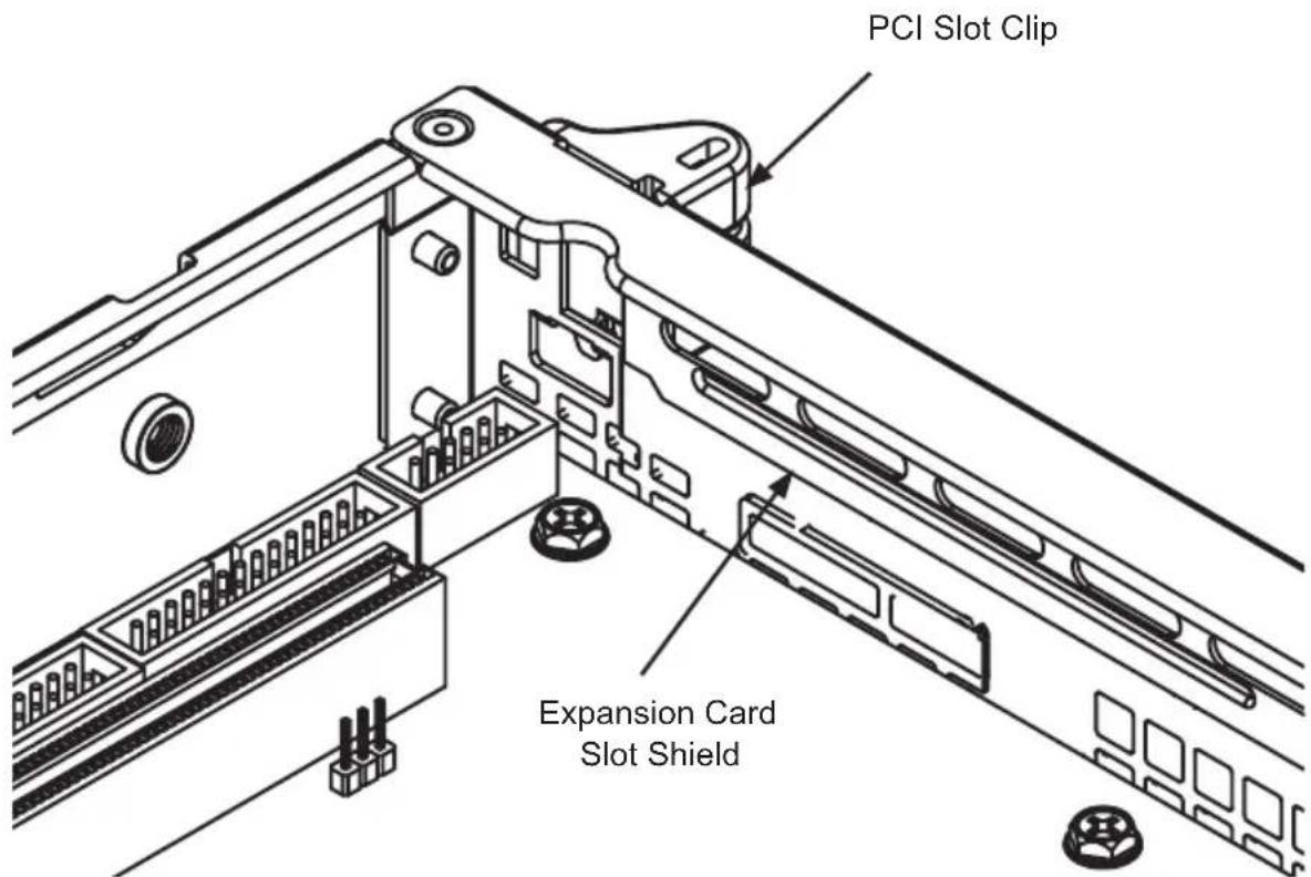
Figure 5-8: Installing the Expansion Card
Installing Expansion Cards
Disconnect the power supply, lay the chassis on a flat surface, and open the 1. chassis cover.
Slide the PCI slot clip upward.2.
Slide the PCI slot shield toward the side of the chassis and remove the 3. shield.
Secure the riser card to the motherboard.4.
Simultaneously slide the expansion card (with "L" bracket) into the PCI slot 5. and the riser card.
Replace the PCI slot clip to secure the expansion card.6.
5-7 Installing the Air Shroud
The air shroud helps cool the chassis by directing heated air through the rear of the chassis. When installing the air fan, be aware of the following:
- The air shroud is designed to fit within the chassis. The sides of the air shroud should remain straight in relation to the top. Do not fold or bend the air shroud.
- The air shroud has perforated tabs that can be removed if motherboard components prevent proper air shroud installation. Do not remove a tab unless it is necessary.

Incorrect Incorrect Correct

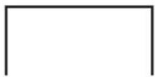
Figure 5-9: Air Shroud Placement

Figure 5-10: Installing the Air Shroud in the SC512 Chassis
Installing The Air Shroud
Confirm that the air shroud matches your chassis model.1.
- Place the air shroud in the chassis. The shroud sets directly behind the system fans. If necessary, remove some perforated tabs to ensure a snug fit.
Installation Complete
In most cases, the chassis power supply and the fans or blower are pre-installed. If you need to install fans, a blower or a power supply, see the following sections of this chapter. If you need to replace the chassis LED panel, see the end of this chapter. If the chassis will be installed into a rack, continue to the next chapter for rack installation instructions.
5-8 System Fans/Blower
SC512F model chassis are cooled with system fans. Three heavy-duty fans provide cooling for the chassis. These fans circulate air through the chassis as a means of lowering the chassis internal temperature.
The SC512F-280 chassis accepts two fans instead of three.

Figure 5-11: Placing the System Fan
System Fan Tray
Systems fan trays are components that house groups of fans. The system fan tray is held in place by two rivets permanently attached to the chassis surface. Each rivet is encircled by a rubber grommet to reduce vibration.
System Fan Tray Replacement
Installing the System Fan Tray
Power down the system.1.
Disconnect each fan from the motherboard.2.
- Lift the system fan tray and fans from the chassis. Retain the rubber mountings that encircle the tray rivets.
Place the fans into the new system fan tray. Make all the fans face the correct 4. direction.
Confirm the the rubber mountings are in place around the chassis rivets.5.
Align the fan tray with rivets and place the new fan tray (and system fans) 6. into the chassis.
Reconnect the system fans to the motherboard7.
Replacing Individual System Fans
Fans can be replaced individually without removing the system fan tray. There is no need to power down the system when replacing a system fan.
Replacing System Fans
If necessary, open the chassis while the power is running to determine which 1. fan has failed. (Never run the server for an extended period of time with the chassis open.)
Remove the failed fan's power cord from the serverboard.2.
Lift the failed fan completely from the chassis.3.
Place the new fan into the vacant space. Make sure the arrows on the top of 4. the fan (indicating air direction) point in the same direction as the arrows on the other fan(s).
Confirm that the fan is working properly and replace the chassis cover..5.
Blower Setup
SC512 chassis models SC512, SC512C and SC512L are blower-cooled. In the unlikely event that the blower fails, replacement is simple and can be accomplished with a Phillips head screwdriver.
Replacing the Blower
Disconnect the chassis from any power source.1.
Remove the two long screws at the front of the blower and the two long 2. screws at the back of the blower and set them aside for later use.
Lift the blower up and out of the chassis and disconnect the wiring.3.
Replace the blower with another blower of the same model and reconnect the 4. wiring.
Align the thru holes in the blower with the thru holes in the chassis. 5.
Secure the blower to the chassis using the screws previously set aside.6.
Close the cover and reconnect power to the chassis.7.
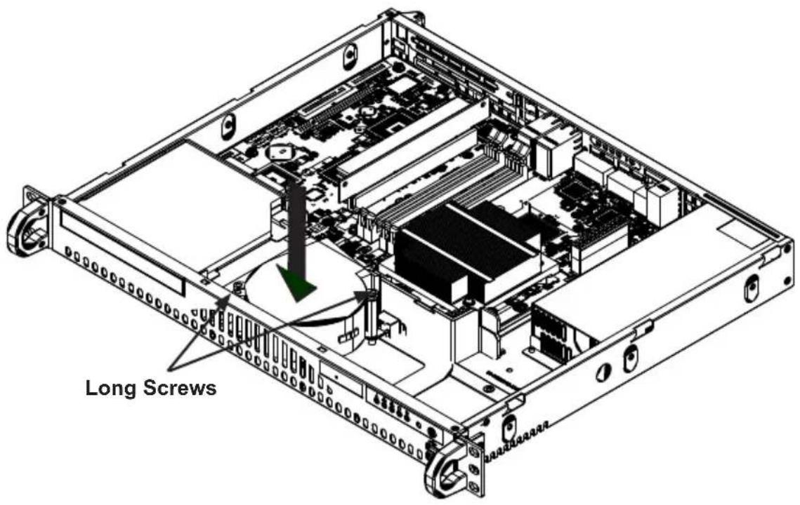
Figure 5-12: Installing the Blower
Checking the Airflow in the Chassis
Make sure there are no objects to obstruct airflow in and out of the server. 1.
Do not operate the server without drives or drive trays in the drive bays. Use 2. only recommended server parts.
Make sure no wires or foreign objects obstruct air flow through the chassis. 3. Pull all excess cabling out of the airflow path or use shorter cables.
The control panel LEDs inform you of system status. See “Chapter 3: System Interface” for details on the LEDs and the control panel buttons.
5-9 Power Supply
Depending on your chassis model the SC512 chassis has a 200, 260, 280, 350, 410, 520 or 600 Watt power supply. This power supply is auto-switching capable. This enables it to automatically sense and operate at a 100v to 240v input voltage. An amber light will be illuminated on the power supply when the power is off. An illuminated green light indicates that the power supply is operating.
Power Supply Failure
The SC512 series chassis has one power supply. In the unlikely event that the power supply unit fails, the system will shut down and you will need to replace it.
Replacement units can be ordered directly from Supermicro (see contact information in the preface) or an authorized reseller.
![Pan Head 6-32 x 5mm [0.197] Remove these screws Power Supply Remove this screw](/content/2026/05/1129292/images/158383672ee245d849f79858624d0f35076377641f6d7ae4a6368ce61bc0dc6a.jpg)
Figure 5-13: Removing the Power Supply
Replacing the Power Supply
Disconnect the power cord from the from the chassis to ensure that the unit is 1. not accidentally plugged in.
Place the chassis on a stable hard surface and remove the chassis cover.2.
- Disconnect the power supply from the motherboard and other chassis components.
Remove the screws securing the power supply. Two screws are in the back 4. of the chassis and one underneath. Retain the screws and the internal brace that connects the power supply to the chassis from underneath.
Pull the power supply out of the chassis. 5.
Place the new power supply into the chassis and secure the power supply 6. using the three screws and internal brace.
Connect the power supply to the motherboard and other chassis components.7.
Connect the power cord to the power supply and power up the chassis/server.8.
Once you confirm that the power supply has been installed correctly, replace 9. the chassis cover.

Figure 5-14: Replacing the LED Panel
Replacing the Chassis LED Panel
In the unlikely event that the chassis LED and buttons fail, the panel can be replaced. Replacement parts can be ordered from Supermicro or an authorized reseller.
Replacing the Chassis LED Panel
Power down and unplug the system.1.
Remove the chassis cover.2.
Disconnect the cord to the front panel.3.
Locate and remove three screws holding the panel in place. (If your chassis 4. supports dual hard drives, you may have to remove the second hard drive from the chassis).
Install the new LED panel and secure the unit with three screws.5.
Reconnect the cables to the LED panel and if necessary, replace the hard 6. drive.
Notes
Chapter 6
Rack Installation
6-1 Overview
This chapter provides a quick setup checklist to install the chassis into a rack.
6-2 Unpacking the System
You should inspect the box the chassis was shipped in and note if it was damaged in any way. If the chassis itself shows damage you should file a damage claim with the carrier who delivered it.
Decide on a suitable location for the rack unit that will hold your chassis. It should be situated in a clean, dust-free area that is well ventilated. Avoid areas where heat, electrical noise and electromagnetic fields are generated. You will also need it placed near a grounded power outlet. Be sure to read the Rack and Server Precautions in the next section.
6-3 Preparing for Setup
The box your chassis was shipped in should include two sets of rail assemblies, two rail mounting brackets and the mounting screws you will need to install the system into the rack. Please read this section in its entirety before you begin the installation procedure outlined in the sections that follow.
Choosing a Setup Location
- Leave enough clearance in front of the rack to enable you to open the front door completely (\~25 inches).
Leave approximately 30 inches of clearance in the back of the rack to allow for sufficient airflow and ease in servicing.
This product is for installation only in a Restricted Access Location (dedicated equipment rooms, service closets and the like).

Warnings and Precautions!

Rack Precautions
- Ensure that the leveling jacks on the bottom of the rack are fully extended to the floor with the full weight of the rack resting on them.
In single rack installation, stabilizers should be attached to the rack.
In multiple rack installations, the racks should be coupled together.
Always make sure the rack is stable before extending a component from the ● rack.
- You should extend only one component at a time - extending two or more simultaneously may cause the rack to become unstable.
General Server Precautions
- Review the electrical and general safety precautions that came with the components you are adding to your chassis.
- Determine the placement of each component in the rack before you install the rails.
Install the heaviest server components on the bottom of the rack first, and then work up.
Use a regulating uninterruptible power supply (UPS) to protect the server from power surges, voltage spikes and to keep your system operating in case of a power failure.
- Allow the hot-plug hard drives and power supply modules to cool before touching them.
Always keep the rack's front door and all panels and components on the servers • closed when not servicing to maintain proper cooling.
Rack Mounting Considerations
Ambient Operating Temperature
If installed in a closed or multi-unit rack assembly, the ambient operating temperature of the rack environment may be greater than the ambient temperature of the room. Therefore, consideration should be given to installing the equipment in an environment compatible with the manufacturer's maximum rated ambient temperature (Tmra).
Reduced Airflow
Equipment should be mounted into a rack so that the amount of airflow required for safe operation is not compromised.
Mechanical Loading
Equipment should be mounted into a rack so that a hazardous condition does not arise due to uneven mechanical loading.
Circuit Overloading
Consideration should be given to the connection of the equipment to the power supply circuitry and the effect that any possible overloading of circuits might have on overcurrent protection and power supply wiring. Appropriate consideration of equipment nameplate ratings should be used when addressing this concern.
Reliable Ground
A reliable ground must be maintained at all times. To ensure this, the rack itself should be grounded. Particular attention should be given to power supply connections other than the direct connections to the branch circuit such as the use of power strips and other devices).
6-4 Rack Mounting Instructions
This section provides information on installing the SC512 chassis into a rack unit with the rails provided. There are a variety of rack units on the market, which may mean the assembly procedure will differ slightly. You should also refer to the installation instructions that came with the rack unit you are using.
NOTE: The SC512F-280/350/410/520/600 chassis models are designed with a wider chassis. The rails for these chassis will fit a rack between 25.6" and 33.05" deep. The following shows how to mount these chassis to a standard rack.
Identifying the Sections of the Rack Rails (Optional Item)
The chassis package includes two rack rail assemblies in the rack mounting kit. Each assembly consists of two sections: an inner fixed chassis rail that secures directly to the server chassis, and an outer fixed rack rail that secures directly to the rack itself.
The SC512F comes with "chassis ears" that allow the chassis to use generic rails.

Figure 6-1: Identifying the Sections of the Rack Rails (Right side rail shown)
Installing the Inner Rail Extension
The SC512F includes chassis ears that you must remove before installing the rails.
Removing the Chassis Ears
Locate and remove the three screws holding the chassis ear in place.1.
Repeat step on with the other chassis ear.2.
![Flat head M4 x 4 mm [0.157]](/content/2026/05/1129292/images/24bc5f15186b55321257ed5ab655356e0adb83c936aa6ad5edae78cb4ab80b78.jpg)
Figure 6-2: Installing Inner Rails to the Chassis
Installing the Inner Rails
- Place the inner rail on the side of the chassis aligning the hooks of the chassis with the rail holes.
Slide the rail toward the front of the chassis to secure the rail in place.2.
Secure the chassis with four screws.3.
Repeat steps 1-3 for the other inner rail extension.4.
![Flat head M5 x 12 mm [0.472] Washer for M5 Secure to the Rear of the Rack Attach Outer Rack Rails together Secure to the Front of the Rack](/content/2026/05/1129292/images/eb45441e3f3a3c4729814eb98722cf3eeae9985219ed63b3efffff6fe3a1a76e.jpg)
Figure 6-3: Assembling the Outer Rails
Installing the Outer Rails to the Rack
Installing the Outer Rails
Attach the short bracket to the outside of the long bracket. You must align the 1. pins with the slides. Also, both bracket ends must face the same direction.
Adjust both the short and long brackets to the proper distance so that the rail 2. fits snugly into the rack.
Secure the long bracket to the front side of the outer rail with two M5 screws 3. and the short bracket to the rear side of the outer rail with three M5 screws. Use a washer with each screw.
Repeat steps 1-4 for the left outer rail.4.

Figure 6-4: Installing the Outer Rails to the Server Rack

natural_image
Isometric line drawing of a server rack cabinet with an open shelf and a green arrow indicating the direction (no text or symbols)Figure 6-5: Installing the Chassis into a Rack
Installing the Chassis into a Rack
Installing the Chassis
Confirm that the inner rails are attached to the chassis. Also, confirm that the 1. outer rails are installed on the rack.
Align chassis rails with the front of the rack rails.2.
Slide the chassis rails into the rack rails, keeping the pressure even on both 3. sides (It may be necessary to depress the locking tabs when inserting). When the server has been pushed completely into the rack, you should hear the locking tabs "click" into the locked position.
(Optional) Insert and tightening the thumbscrews that hold the front of the 4. server to the rack.
Mid-Mount Telco Rack
The SC512.supports Telco rack installation. The SC512 chassis compact design allows the chassis to be installed into a Telco rack without the use of rails.
![Place chassis ears here Flat head M4 x 4 mm [0.157]](/content/2026/05/1129292/images/c3f89dabc0066dd52e7518c0366327eb5efa1accd071755408bdc99d5970c40f.jpg)
Figure 6-6: Moving the Chassis Ears for Telco Rack Installation
Installing the Chassis into a Rack in Mid-Mount Position
Instaling into a Mid-Mount Position Rack
If it is necessary to install the chassis in a mid-mount Telco rack, remove the 1. chassis rails and the chassis ears (if the ears are installed at the front of the chassis).
Locate the three screw holes in the middle of the chassis and secure the ears 2. to the chassis with three flat head screws. Make sure the screws are secure, but do not over tighten the screws.
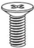
Flat head
M5 x 12 mm [0.472]
Washer for M5

natural_image
Isometric line drawing of a server rack unit with vertical racks and a central-mounted device (no text or symbols)Figure 6-7: Installing the Server into a Telco Rack
Hold the chassis in the telco rack and screw the chassis to the rack using the 3. three screw holes located in the chassis ears.
The chassis is held in place by the chassis ears and does not slide in and out 4. of place.
Appendix A
Cables, Screws, and Other Accessories
A-1 Overview
This appendix lists supported cables for your chassis system. It only includes the most commonly used components and configurations. For more compatible cables, refer to the manufacturer of the motherboard you are using and our Web site at: www.supermicro.com.
A-2 Cables Included with SC512 Chassis
| SC512-200 and SC512-260 | |||
| Part # Type | Length Description | ||
| CBL-0049L Cable | Front cable | 16-pin to 16-pin | |
| CBL-0084L Wire 9 | cm DVD cable (lead free). | ||
| CBL-0260L US power cord 18 | AWG | ||
| CBL-0261L Cable | 40 cm 40cm | 7-pin SATA cable S-RA | |
| CBL-0262L Cable | 4-pin to 1x SATA (RA) + 1x 4-pin (RA) + 1x FPD PWS | ||
| CBL-0263L Cable | 77 cm 9-pin | to 9-pin internal | USB cable |
| SC512F-260 | |||
| Part # Type | Length Description | ||
| CBL-0049L Cable | Front cable | 16-pin to 16-pin | |
| CBL-0084L Wire 9 | cm DVD cable (lead free). | ||
| CBL-0260L US power cord 18 | AWG | ||
| CBL-0262L Cable | 4-pin to 1x SATA (RA) + 1x 4-pin (RA) + 1x FPD PWS | ||
| CBL-0263L Cable | 77 cm 9-pin | to 9-pin internal | USB cable |
| SC512F-280 | |||
| Part # Type | Length Description | ||
| CBL-0142L Cable | 30 cm (~12") | 7-pin SATA with two 90 degree side connectors (lead free). | |
| CBL-0156L Cable | 40 cm 16-pin to 16-pin FP cable. Lead free. | ||
| CBL-0084L Wire 9 | cm DVD cable. Lead free. | ||
| - Cable 6' | Regional power cord | ||
| SC512F-350 | |||
| Part # Type | Length Description | ||
| CBL-0142L Cable | 30cm 7-pin | 2-side SATA | RA-RA cable |
| CBL-0156L Cable | 40cm | Front ctrl cable round 16-pin to 16-pin | |
| CBL-0260L | Cord | 6 feet | US power cord 18AWG |
| CBL-0261L Cable | 40cm | 7-pin | SATA cable S-RA |
| CBL-0262L Cable | - | 4-pin to 1x SATA (RA) + 1x4-pin (RA) + 1x FPD PWS EXT. cable | |
| SC512F-410 | |||
| Part # Type | Length Description | ||
| CBL-0142L Cable | 30 cm (~12") | 7-pin SATA with two 90 degree side connectors (lead free). | |
| CBL-0156L Cable | 40 cm 16-pin to 16-pin FP cable. Lead free. | ||
| CBL-0084L Wire 9 | cm DVD cable (lead free). | ||
| SC512F-520 | |||
| Part # Type | Length Description | ||
| CBL-0142L Cable | 30 cm (~12") | 7-pin SATA with two 90 degree side connectors (lead free). | |
| CBL-0156L Cable | 40 cm 16-pin to 16-pin FP cable (lead free). | ||
| CBL-0084L Wire 9 | cm DVD Cable (lead free). | ||
| - Cable 6' | Regional power cord | ||
| SC512F-600 | |||
| Part # Type | Length Description | ||
| CBL-0142L Cable | 30 cm (~12") | 7-pin SATA with two 90 degree side connectors (lead free). | |
| CBL-0156L Cable | 40 cm 16-pin to 16-pin FP cable (lead free). | ||
| - Cable 6' | Regional power cord. | ||
| SC512F-520L and SC512F-600L | |||
| Part # Type | Length Description | ||
| CBL-0142L Cable | 30 cm (~12") | 7-pin SATA with two 90 degree side connectors (lead free). | |
| CBL-0156L Cable | 40 cm 16-pin to 16-pin FP cable (lead free). | ||
| - Cable 6' | Regional power cord | ||
| SC512L-200 and SC512L-260 | |||
| Part # Type | Length Description | ||
| CBL-0049L Cable | Front cable | 16-pin to 16-pin | |
| CBL-0084L | Wire | 9 cm DVD | cable (lead free). |
| CBL-0260L | US power cord 18 AWG | ||
| CBL-0261L Cable | 40 cm | 40 cm 7-pin SATA | SATA cable S-RA |
| CBL-0262L Cable | 4-pin to 1x SATA (RA) + 1x 4-pin (RA) + 1x FPD PWS | ||
| CBL-0263L Cable | 77 cm | 9-pin to 9-pin internal USB cable | |
| SC512L-260-LCD | |||
| Part # Type | Length Description | ||
| CBL-0049 Cable 9 | cm 16-pin to 16-pin ribbon cable | ||
| CBL-0121 USB 2.0 | 10-pin to 4-pin cable for LCD | ||
Extending Power Cables
Although Supermicro chassis are designed with to be efficient and cost-effective, some compatible motherboards have power connectors located in different areas.
To use these motherboards you may have to extend the power cables to the mother boards. To do this, use the following chart as a guide.
| Power Cable Extenders | ||
| Number of Pins Cable | Part # Length | |
| 24-pin CBL-0042 | 7.9"(20 CM) | |
| 20-pin CBL-0059 | 7.9"(20 CM) | |
| 8-pin CBL-0062 | 7.9"(20 CM) | |
| 4-pin CBL-0060 | 7.9"(20 CM) | |
Front Panel to the Motherboard
The SC512 chassis includes a cable to connect the chassis front panel to the motherboard. If your motherboard uses a different connector, use the following list to find a compatible cable.
| Front Panel to Motherboard Cable (Ribbon Cable) | ||
| Number of Pins(Front Panel) | Number of Pins(Motherboard) | Cable Part # |
| 16-pin 16-pin CBL-0049 | ||
| 16-pin 20-pin CBL-0048 | ||
| 20-pin 20-pin CBL-0047 | ||
| 16-pin varies* CBL-0068 | ||
| 20-pin varies* CBL-0067 | ||
* Split cables: Use these cable if your motherboard requires several different connections from the front panel.
A-3 Routing the Chassis Cables
In order for the SC512 chassis to perform safely and efficiently, it is important that the cables are routed correctly. Follow the instructions below and review both the cabling diagram and photograph to ensure that the cabling has been properly routed.
Preparing the Chassis for Cable Routing
Unplug the chassis from any power source.1.
Review the diagram on the following page, taking note of the naming of each 2. cable.
Remove the screws securing the fan platform to the bottom of the chassis.3.

Figure A-1: Chassis Cable Routing Diagram (SC512L-200/260)
Routing Cable (1A) from Hard Drive (1B)
Plug cable (1A) into the SATA port of hard drive (1B).1.
Lift up the fan and run cable (1A) straight out from the port and under the fan.2.
Route cable (1A) over the hard drive and through the left middle bracket.3.
Plug cable (1A) into upper SATA port (1C) on the motherboard.4.
Routing Cable (2A) from Hard Drive (2B)
Plug cable (2A) into the SATA port of hard drive (2B).1.
Run cable (2A) upwards at a right angle, up and over the top of hard drive 2. (2B).
Route cable (2A) through the left middle bracket.3.
Plug cable (2A) into lower SATA port (2C) on the motherboard.4.
Routing Split Cable (3A)(4A) from Hard Drives (1B)(2B) to the Power Supply
Plug the end of the split cable (3A) into hard drive (2B).1.
Route the end of the split cable (3A) straight up at a right angle, beside the 2. fan, and over the top of cable (1A).
Plug the end of the split cable (3A) into connector (3B).3.
Plug the other end of the split cable (4A) into hard drive (1B). 4.
Route the end of the split cable (4A) straight up at a right angle, along the top 5. of the fan.
- Route cable (5A) through the right middle bracket and plug it into connector (3B).
Checking the Cable Routing
Check the cable routing by following out each cable in the previous steps and 1. comparing them to the diagram in Figure A-1, and the photograph in Figure A-2.

natural_image
Interior view of a SuperMicro server rack with visible CPU, RAM slots, and wiring (no text or symbols on main components)Figure A-2: Chassis Cable Routing
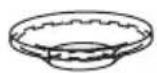
A-4 Chassis Screws
The Chassis and accessory box include all the screws needed to setup your chassis. This section includes descriptions of the most common screws used. Your chassis may not require all the parts listed.
M/B
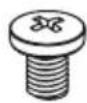
Pan head
6-32×5mm
[0.197]
HARD DRIVE

Flat head
6-32×5mm
[0.197]
DVD-ROM CD-ROM FLOPPY DRIVE
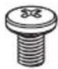
Pan head
6-32×5mm
[0.197]

Flat head
6-32×5mm
[0.197]

Round head
3 × 5 mm
[0.197]

Round head
2.6×5mm
[0.197]
RAIL

Flat head
M4 x 4 mm
[0.157]

Round head
M4 x 4 mm
[0.157]
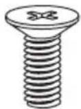
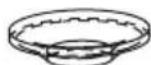
Flat head
M5 x 12 mm [0.472]
Washer for M5
M/B STANDOFF

M/B standoff
6-32 to 6-32
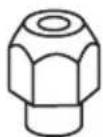
M/B (CPU) standoff
M5 to 6-32

Thumb screw
6-32 x 5 mm [0.197]
Figure A-3: Chassis Screws
Appendix B
Power Supply Specifications
This appendix lists power supply specifications for your chassis system.
| SC512 Chassis Model | ||
| 200 260 | ||
| MFR Part # PWS-201-1H PWS-0055 | ||
| Rated AC Voltage | 100 - 240V50 - 60Hz4 - 2A Max | 100 - 240V60 - 50Hz4A Max |
| +5V standby | 2.0A 2.0A | |
| +12V | 16.0A 18.0A | |
| +5V | 8.0A 25.0A | |
| +3.3V | 8.0A 15.0A | |
| -12V | 0.5A 1.0A | |
| SC512C Chassis Models | ||
| 200 260 | ||
| MFR Part # PWS-0043 | PWS-0055 | |
| Rated AC Voltage | 100 - 240V60 - 50Hz5 - 3A | 100 - 240V60 - 50Hz4A Max |
| +5V standby | 2.0A 2.0A | |
| +12V | 12.0A 18.0A | |
| +5V | 20A 25.0A | |
| +3.3V | 17.0 A 15.0A | |
| -12V | 0.8A 1.0A | |
| SC512F Chassis Models (See below for 410 model) | |||||
| 260 280 | 350 520/520L | 600/600L | |||
| MFR Part # | PWS-0055 | PWS-281-1H | PWS-351-1H | PWS-521-1H | PWS-601-1H |
| Rated AC Voltage | 100 - 240V60 - 50Hz4A Max | 100 - 240V50 - 60Hz5A Max | 100-240 V,50-60 Hz,4.2 - 1.8A | 100 - 240V50 - 60Hz7 - 3A | 100 - 240V50 - 60Hz7.5 - 3.1A |
| +5V standby | 2.0A 2A 3A | 3A 3A | |||
| +12V | 18.0A 23A 29A | 39A 49A | |||
| +5V | 25.0A 18A 18A | 20A 20A | |||
| +3.3V | 15.0A 15A 15A | 16A 16A | |||
| -12V | 1.0A 1A - 0.5A | 0.5A | |||
| SC512F-410 Chassis Model | |
| 410 | |
| MFR Part # | PWS-0061 |
| DC Voltage | Voltage Range = -36V to -72VNominal Voltage = -48VMax Input Current = 18A @ -48V |
| DC Output | 5V + 3.3V ≤ 180W |
| +5V standby | 35.0A |
| 3.0A | |
| +12V | 32.0A |
| -12V | 0.5A |
| +3.3V | 20.0A |
| SC512L Chassis Models | ||
| 200 | 260/260-LCD | |
| MFR Part # | PWS-0043 | PWS-0055 |
| Rated AC Voltage | 100 - 240V60 - 50Hz5-3A | 100 - 240V60 - 50Hz4A Max |
| +5V standby | 2.0A | 2.0A |
| +12V | 12.0A | 18.0A |
| +5V | 20A | 25.0A |
| +3.3V | 17.0A | 15.0A |
| -12V | 0.8A | 1.0A |
Notes
Disclaimer (cont.)
The products sold by Supermicro are not intended for and will not be used in life support systems, medical equipment, nuclear facilities or systems, aircraft, aircraft devices, aircraft/emergency communication devices or other critical systems whose failure to perform be reasonably expected to result in significant injury or loss of life or catastrophic property damage. Accordingly, Supermicro disclaims any and all liability, and should buyer use or sell such products for use in such ultra-hazardous applications, it does so entirely at its own risk. Furthermore, buyer agrees to fully indemnify, defend and hold Supermicro harmless for and against any and all claims, demands, actions, litigation, and proceedings of any kind arising out of or related to such ultra-hazardous use or sale.


- SC512 Chassis Series
- USER'S MANUAL
- Preface
- About This Manual
- Manual Organization
- Chapter 1: Introduction
- Chapter 2: System Safety
- Chapter 3: Chassis Components
- Chapter 4: System Interface
- Chapter 5: Chassis Setup and Maintenance
- Chapter 6: Rack Installation
- Table of Contents
- Chapter 1 Introduction
- Chapter 2 System Safety
- Chapter 3 Chassis Components
- Chapter 4 System Interface
- Chapter 5 Chassis Setup and Maintenance
- Chapter 6 Rack Installation
- Notes
- Chapter 1
- Introduction
- 1-1 Overview
- 1-2 Chassis Features
- CPU
- I/O Expansion slots
- Peripheral Drives
- Dual Hard Drives
- 1-3 Contacting Supermicro
- Headquarters
- Europe
- Asia-Pacific
- 1-4 Returning Merchandise for Service
- Chapter 2
- System Safety
- 2-1 Overview
- 2-2 Warnings and Precautions
- 2-3 Preparing for Setup
- 2-4 Electrical Safety Precautions
- 2-5 General Safety Precautions
- 2-6 System Safety
- Chapter 3
- Chassis Components
- 3-1 Overview
- 3-2 Components
- Chassis
- Fans
- Blower
- Mounting Rails
- Power Supply
- Air Shroud
- 3-3 Where to get Replacement Components
- 3-4 Chassis Model Options
- Identifying Fan and Blower-Cooled Chassis Models
- Model SC512
- Model SC512C
- Model SC512F
- Model SC512L
- Chapter 4
- System Interface
- 4-1 Overview
- 4-2 Control Panel Buttons
- 4-3 Control Panel LEDs
- Chapter 5
- Chassis Setup and Maintenance
- 5-1 Overview
- 5-2 Installation Procedures
- General Maintenance
- 5-3 Removing the Chassis Cover
- Removing the Chassis Cover
- 5-4 Installing Hard Drives
- Installing a Hard Drive
- 5-5 Installing the Motherboard
- Important Motherboard Installation Information
- I/O Shield Backplate
- Heatsinks
- Standoffs
- Installing the Motherboard
- 5-6 Installing the DVD or CD-ROM Drive
- Replacing the DVD or CD-ROM
- PCI Slot Setup
- Installing Expansion Cards
- 5-7 Installing the Air Shroud
- Installing The Air Shroud
- Installation Complete
- 5-8 System Fans/Blower
- System Fan Tray
- System Fan Tray Replacement
- Replacing Individual System Fans
- Replacing System Fans
- Blower Setup
- Replacing the Blower
- Checking the Airflow in the Chassis
- 5-9 Power Supply
- Power Supply Failure
- Replacing the Power Supply
- Replacing the Chassis LED Panel
- Chapter 6
- Rack Installation
- 6-1 Overview
- 6-2 Unpacking the System
- 6-3 Preparing for Setup
- Choosing a Setup Location
- Warnings and Precautions!
- Rack Precautions
- General Server Precautions
- Rack Mounting Considerations
- Ambient Operating Temperature
- Reduced Airflow
- Mechanical Loading
- Circuit Overloading
- Reliable Ground
- 6-4 Rack Mounting Instructions
- Identifying the Sections of the Rack Rails (Optional Item)
- Installing the Inner Rail Extension
- Removing the Chassis Ears
- Installing the Inner Rails
- Installing the Outer Rails to the Rack
- Installing the Outer Rails
- Installing the Chassis into a Rack
- Installing the Chassis
- Mid-Mount Telco Rack
- Installing the Chassis into a Rack in Mid-Mount Position
- Appendix A
- Cables, Screws, and Other Accessories
- A-1 Overview
- A-2 Cables Included with SC512 Chassis
- Extending Power Cables
- Front Panel to the Motherboard
- A-3 Routing the Chassis Cables
- Preparing the Chassis for Cable Routing
- Routing Cable (1A) from Hard Drive (1B)
- Routing Cable (2A) from Hard Drive (2B)
- Routing Split Cable (3A)(4A) from Hard Drives (1B)(2B) to the Power Supply
- Checking the Cable Routing
- A-4 Chassis Screws
- Appendix B
- Power Supply Specifications
- Disclaimer (cont.)
Brand : Supermicro
Model : SuperChassis 512L-260-LCD
Category : Computer case