Integra Vitro - Solar panel Scheuten Solar - Free user manual and instructions
Find the device manual for free Integra Vitro Scheuten Solar in PDF.

| Product Type | Photovoltaic Solar Panel |
| Brand | Scheuten Solar |
| Model | Integra Vitro |
| Dimensions (L x W x H) | 1650 x 990 x 35 mm |
| Weight | 18.5 kg |
| Power Output (Peak) | 270 Wp |
| Cell Type | Monocrystalline Silicon |
| Efficiency | 16.5% |
| Operating Voltage | 30.5 V |
| Current at Max Power | 8.85 A |
| Open Circuit Voltage | 37.8 V |
| Short Circuit Current | 9.40 A |
| Maximum System Voltage | 1000 V DC |
| Frame Material | Anodized Aluminum |
| Glass Thickness | 3.2 mm Tempered Glass |
| Main Functions | Direct sunlight to electrical energy conversion; grid-tied or off-grid systems |
| Maintenance and Cleaning | Clean with water and a soft sponge; avoid abrasive cleaners; periodic inspection of connections |
| Safety | Use insulated tools; disconnect before maintenance; avoid shading to prevent hot spots |
| Spare Parts and Repairability | Contact authorized service center; replace damaged glass or junction box; do not disassemble cells |
| General Information | 25-year linear performance warranty; certified to IEC 61215 and IEC 61730 |
Frequently Asked Questions - Integra Vitro Scheuten Solar
User questions about Integra Vitro Scheuten Solar
0 question about this device. Answer the ones you know or ask your own.
Ask a new question about this device
Download the instructions for your Solar panel in PDF format for free! Find your manual Integra Vitro - Scheuten Solar and take your electronic device back in hand. On this page are published all the documents necessary for the use of your device. Integra Vitro by Scheuten Solar.
USER MANUAL Integra Vitro Scheuten Solar
Solar Energy Solutions of Scheuten Solar: Installation Manual MS Integra Vitro Landscape and Portrait
September 2012, Version 1.6
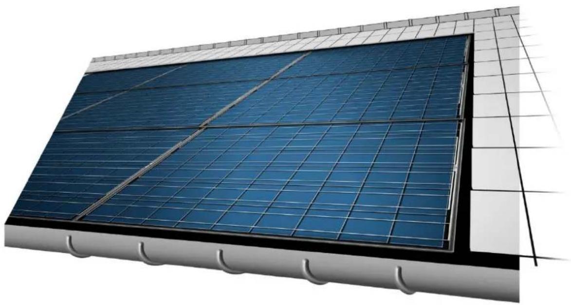
natural_image
Exterior view of a modern building facade with blue solar panels mounted on a grid-patterned roof (no text or symbols visible)MS Integra Vitro
Mounting Directions for In-Roof Photovoltaic Systems
Contents
1 About this Installation Manual....4
1.1 Revisions 4
1.2 Validity 4
1.3 Target Group 4
1.4 Warnings, Symbols, Displays .... 4
1.4.1 Warnings in this document 4
1.4.2 Symbols and Displays....5
2 Safety Instructions 6
2.1 Use According to Regulations....6
2.2 Safety Regulations....6
2.3 Personnel Qualifications....6
2.4 Changes to the mounting system 6
2.5 Sources of Danger 6
2.5.1 Electrical Installation 6
2.5.2 Working on the Roof 7
2.6 Fire Safety 7
3 Instructions....8
3.1 Overview....8
3.2 Integra-framed photovoltaic modules....9
3.3 Roof structure 10
3.4 Mounting Clamps 11
3.5 Required Components for In-Roof Mounting / Flashing 12
3.5.1 Flashing profiles 12
3.5.2 Flashings 12
3.5.3 Eaves skirting, seam sealing strip and bottom mounting clamps 15
4 Mounting....16
4.1 Tools, Auxiliary Material .... 16
4.2 Preliminary Steps....16
4.2.1 Structural Calculations in Accordance with Eurocode I and 5 ...... 16
4.2.2 PV System Size....17
4.2.3 Define the substructure 17
4.2.4 Prepare the substructure....20
4.3 In-roof mounting of the PV-system....20
4.3.1 Installing the Photovoltaic Modules 21
4.3.2 Roof Seams....25
4.4 Wiring....28
4.5 Potential Equalization and Lightning Protection 28
5 Connecting to the Inverter 30
6 Dismounting....30
7 Control 31
8 Disposal 31
9 Parts List....32
9.1 Accessories MS Integra Vitro 33
1 About this Installation Manual
Multisol® Integra Vitro modules are application class A in accordance with EN IEC 61730.
Multisol® Integra Vitro modules are quality products produced using high quality solar cells made of crystalline silicon. All materials used have been carefully selected and processed to a robust double glass PV module. That is why Multisol® Integra Vitro modules have an especially long life cycle. It is important that the information provided below is observed. These instructions should be read carefully and need to be fully observed before installation, initial operation and during maintenance of photovoltaic systems that use Multisol® Integra Vitro PV modules.

Danger! Risk of death or serious injury if not observed! It is crucial therefore that any work performed on PV systems is carried out exclusively by skilled professionals who have the respective training.
These instructions describe a quick and reliable in-roof installation of the photovoltaic system.
→ Read this manual carefully before starting with the installation.
→ Keep this manual for as long as the photovoltaic system is in use.
The latest version of the manual can be downloaded at http://www.scheutensolar.com
→ Be sure that this manual can be made available to the operator at all times.
→ Hand this manual on to all subsequent owners or users of the photovoltaic system.
→ Insert all supplemental information received from Scheuten Solar or your local supplier.
→ Heed all other applicable documents, in particular the standard installation manual for Multisol PG-54
1.1 Revisions
| Date | Version | What's new? |
| 12 Feb. 2009 | 1 | complete update |
| 20 April 2009 | 1.1 | potential equalization supplement |
| 01 Nov. 2010 | 1.2 | potential equalization supplement |
| 01 April 2011 | 1.3 | About this manual |
| Fire Safety (update) | ||
| Change of article numbers | ||
| Table 3-3 - change of dimensions | ||
| November 2011 | 1.4 | Integra Vitro Portrait |
| Design and guidelines taking into account strength requirements | ||
| January 2012 | 1.5 | Update Chapter 4Grid size adjustment |
| September 2012 | 1.6 | General Update |
Table 1-1: Revisions
1.2 Validity
This manual is valid exclusively for the installation of the PV modules MS Integra Vitro Landscape and Portrait by Scheuten Solar.
1.3 Target Group
This manual is intended for installers as well as for qualified technicians specialized in mounting, operating and maintenance of photovoltaic systems.
1.4 Warnings, Symbols, Displays
1.4.1 Warnings in this document
In this instruction manual warning signs are used in order to prevent injuries and damages.
→ Read and always heed these warning signs.
Warnings are marked by the following symbols and terms:

DANGER
Imminent Danger.
Negligence can lead to death or serious injury.

WARNING
Impending Danger.
Negligence could lead to death or serious injury.

CAUTION
Dangerous Situation.
Negligence could lead to injury.
CAUTION
Critical Situation.
Negligence could lead to material damage.

TIP
Important information towards understanding or towards optimizing the process of installation.
1.4.2 Symbols and Displays
In this installation manual symbols and displays are used to facilitate comprehension.
| Symbol | Meaning |
| √ | Prerequisite to this specific stage of installation. |
| → | Installation stage with one or more steps, the order of which is not important. |
| 1.2.3. ... | Installation stage with several steps, the order of which is relevant and therefore listed. |
| •— | Listing at the first levelListing at the second level, including stage instructions |
| (cf. chapter) | Cross reference within this installation manual |
Table 1-2: Symbols and Displays
2 Safety Instructions
2.1 Use According to Regulations
The photovoltaic system is intended solely for the generation of solar power. Mounting is to occur only upon roof constructions in accordance with the present installation manual.
There is no guarantee for alternative applications, even if analogous. Categorically any such application is not in accordance with regulations.
2.2 Safety Regulations
The installer and operator of the photovoltaic system are responsible for seeing that all relevant legal regulations and guides are adhered to.
→ Start, operate and maintain the photovoltaic system only in accordance with the following regulations and standards.
- Installation manual
• Applicable product datasheet
- Warning labels and instructions on the photovoltaic module
- Valid international, national and local regulations relevant for the specific system, especially related to, the installation of photovoltaic systems, working with direct current and regulations of the local power company for operation of a solar power system
• Building regulations
• Regulations concerning accident prevention
2.3 Personnel Qualifications
The operator and the installer are responsible for engaging only trained and schooled specialists to carry out installation, maintenance, initial operation and dismounting. Ensure all personnel
→ have understood this manual and are capable of implementing the instructions.
→ are familiar with and adhere to the safety regulations.
→ use appropriate protective clothing and equipment and take adequate measures to prevent accidents.
2.4 Changes to the mounting system
Changes to the mounting system or installation procedure can damage the photovoltaic module or impair its proper functioning.
→ Follow the installation instructions, design, procedures and prescribed materials, as described in this manual.
2.5 Sources of Danger
The photovoltaic module is a product made of glass and should be handled as such.
→ Do not place against bare edging.
→ Do not step on, or load improperly.
2.5.1 Electrical Installation
→ Ensure that the electrical installation and initial operation is carried out by a licensed electrician.
→ Be aware that even at low-light conditions, modules are almost at full voltage.
Do not exceed the maximum permissible system voltage of the photovoltaic modules, even at low temperatures.
Electric Arcs on DC Conductors!
Simultaneous contact to both poles causes fatal injury.
→ Do not sever live cables.
→ Bare cable ends should be connected or insulated.
Voltage Higher than Safety Extra-Low Voltage (SELV)!
Injury to persons due to summation of voltage during series connection
→ Observe proper safety and protection measures.
Dampness during Electrical Installation!
Injury to persons, damage to the system
→ Carry out work on the system only on a dry under surface.
→ During installation see that photovoltaic modules, wiring, etc., are dry.
2.5.2 Working on the Roof

TIP
Safety regulations state that work higher than 3 meters (eaves height) requires scaffolding with safety nets.
If it is not possible to put up scaffolding or if the roof is very steep:
→ Follow up all relevant regulations for working on a roof.
2.6 Fire Safety
The PV modules used are certified according to fire resistance class C (fundamental fire resistance) based on ANSI / UL 790.
Products that comply with these tests
• are not readily flammable.
• afford a reasonable degree of fire protection to the roof deck.
- don't slip from position
• are not sensitive to produce flying burning particles that might propagate the fire.
In accordance with EN-IEC 61730-1 and local building codes under the modules a fire-resistant roof covering must be present rated for the application.
3 Instructions
3.1 Overview
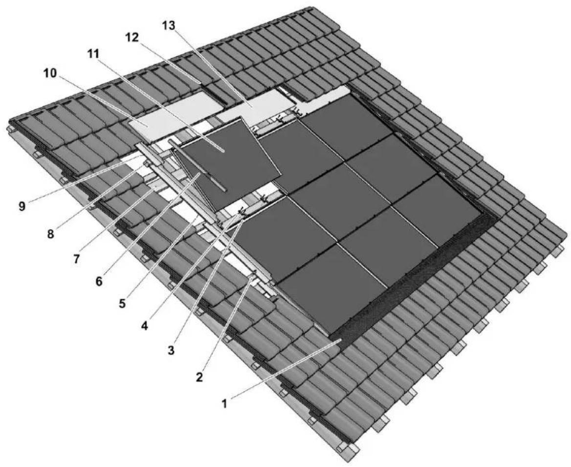
Image 3-1: Exploded view of the photovoltaic system
1 Eaves-side skirting and sealing tape
2 Sheet grips
3 Mounting clamp
4 SS full-thread pan head screws (4.5 x 35)
5 Flashing (left side)
6 Flashing profile (left)
7 Integra batten 120 x 28 (min.)
8 Batten for roof tiles
9 Side flashing upper left
10 Ridge-side flashing left corner
II Integra-framed photovoltaic module
12 Join capping piece
13 Flashing ridge middle
3.2 Integra-framed photovoltaic modules
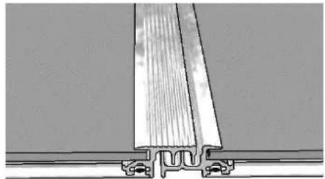
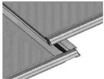
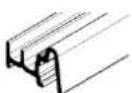
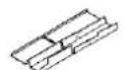
Multisol Integra Vitro modules are Multisol Vitro laminates fitted with a special SOLRIF® profile frame. The profile frames of adjoining modules interlock like roof tiles, image 3-2A. The top side of the modules has a rubber lip, image 3-2B, preventing water to be blown under the PV structure. The water can flow freely to the gutter as the bottom side has only a frame under the module. This results in a rainproof roof like a conventional tile roof. To obtain a watertight construction under all weather conditions, a roofing sheet is needed under the modules. This can also take care of condensation.
natural_image
Technical line drawing of a structural joint or bracket assembly (no text or symbols)Image 3-2 A: Interlocking left and right side
natural_image
Close-up of a structural joint or bracket detail (no text or symbols visible)3-2 B: Top and bottom sealing with rubber strip
Ready to mount INTEGRA-framed photovoltaic modules for in-roof installation can be obtained in the following variants:
• Scheuten Multisol INTEGRA VITRO PG-54 Landscape
• Scheuten Multisol INTEGRA VITRO PG-54 Portrait
| DimensionsScheuten Integra Vitro | P6-54 LandscapeL x W | P6-54 PortraitL x W |
| Framed module (mm) | 1020 x 1538 | 1520 x 1038 |
| Thickness laminate (mm) | 7.0 | 7.0 |
| Thickness Junction Box (mm) | 27 | 27 |
| Thickness frame (mm) | 20 | 20 |
| Grid size [mm] | 988 x 1522 | 1488 x 1022 |
| Mass (kg) | 25 | 25 |
| Frame | Solrif D Landscape | Solrif D Portrait |
Table 3-1: Dimensions of the photovoltaic modules
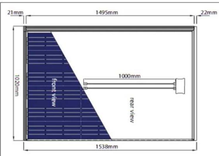
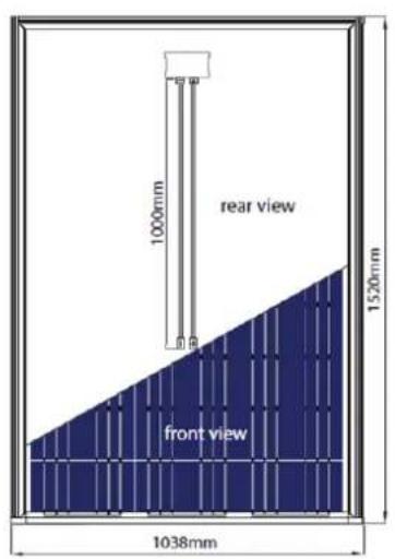
Image 3-3: Framed photovoltaic modules Landscape and Portrait
3.3 Roof structure
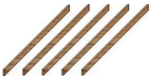
natural_image
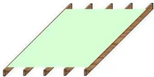
Four identical wooden beams arranged diagonally (no text or symbols)Image 3-4: Basic roof structures
A: Beams
B: Beams with decking
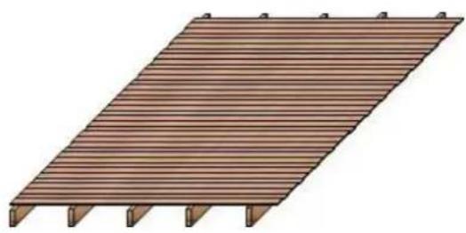
natural_image
Illustration of a wooden deck structure with slatted edges and supports (no text or symbols)Mounting an Integra Vitro module is based on a standard roof structure as shown in image 3.4 with beams and in most cases a decking.
On top of this standard roof a dedicated structure must be made consisting of standard wooden battens.
In this manual the minimum dimensions are given that allow for sufficient strength, ventilation and distance to cope with the module bending, during the maximum suction and pressure load that the Integra PV system is designed for.
Under the PV system a fire resistant layer must be attached that has a fire class rated for the application, determined according to EN 13501-5, and takes into account the high temperatures (up to 90^ ) under a PV system. Another function of this layer is to shield the interior from condensation from the PV modules.
natural_image
Simple 3D diagram of a wooden fence with a green shaded area on top, no text or symbols present.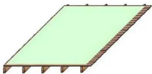
natural_image
Simple 3D diagram of a rectangular structure with green fill and brown hatched edges, no text or symbols present.Image 3-5: Roofs with fire resistant under layer
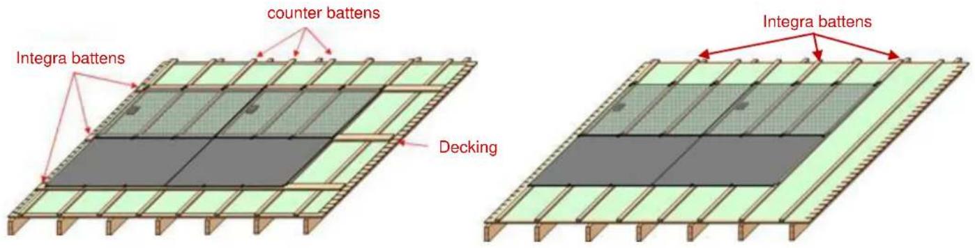
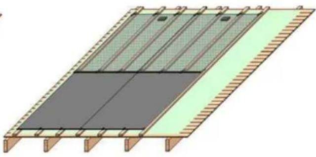
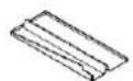
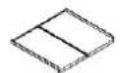
Image 3-6: Landscape Integra
A: mounted on horizontal battens
B: mounted on vertical battens
To mount the Integra modules, it is possible to use horizontal or vertical battens. The latter situation is preferred in case of "flat" roof tiles, as this results in a system that lies more in plane of the tiles. A disadvantage is the lower distance between module and decking, and consequently less cooling of the PV modules.
natural_image
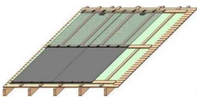
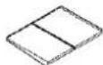
Architectural diagram of a roof structure with green and gray panels, no text or symbols presentImage 3-7: Portrait Integra
A: mounted on horizontal Integra battens
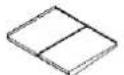
natural_image
Architectural diagram of a roof structure with green and gray panels, no text or symbols presentB: mounted on vertical Integra battens
| Battens | Dimensions |
| Horizontal Integra | 120 x 28 mm |
| Vertical Integra | 50 x 34 mm |
| Counter Battens | 34 x 22 mm |
Table 3-2: Minimum dimensions of roof battens WxH (softwood construction timber)
In chapter 4 the mounting procedures of the PV system and the relation between design and strength will be described in detail.
3.4 Mounting Clamps
The Scheuten Integra Vitro modules framed with Solrif ^® D Landscape or Portrait profile frames are braced to the substructure with mounting clamps.
Four different types of clamps can be used:
| Picture | Description | Dimensions (LxW) |
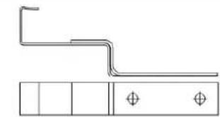 | Mounting clamp "Profile", black | 103.5 x 16.5 mm |
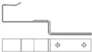 | Mounting clamp "Profile Portrait" | 118.5 x 16.5 mm |
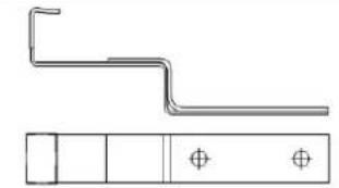 | Mounting clamp "Glass", black | 103.5 x 16.5 mm |
 | Mounting clamp "Glass Portrait", black | 118.5 x 37 mm |
Table 3-3: Overview of mounting clamp types
Article numbers are presented in table 9-1.
All clamps have in common:
Material gauge: 1.5 + 2.0 mm
Material: Stainless spring steel type 1.4310
Screw type: SS (Stainless Steel) full-thread pan head screws (4.5 x 35) high grade (2 or 3 screws).
The mounting clamp "profile" is used to brace two modules respectively to their frames in the overlapping area.
Additional clamps "glass" are needed in the glass area, due to the large module size. The necessary number of glass clamps depends on the suction load the system has to be designed for. To limit the number of glass clamps in case of the Portrait design, an especially strong clamp is developed: "Glass Portrait". To protect the glass, the front side of the clamp has been coated with weather proof plastic.
3.5 Required Components for In-Roof Mounting / Flashing
Often the module surface of the system, based upon the grid measure of the modules, does not correspond exactly with the measurements of the roof itself. In this case, the rest of the roof surface must be integrated into the system by means of flashing profiles and flashings, which can be delivered.
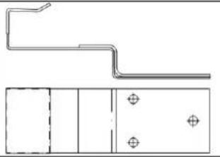
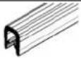
3.5.1 Flashing profiles
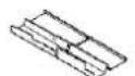
For in-roof mounting, special profiles for flashings on the right and left sides of the system are available as an option. They allow a uniform transition to the seams.
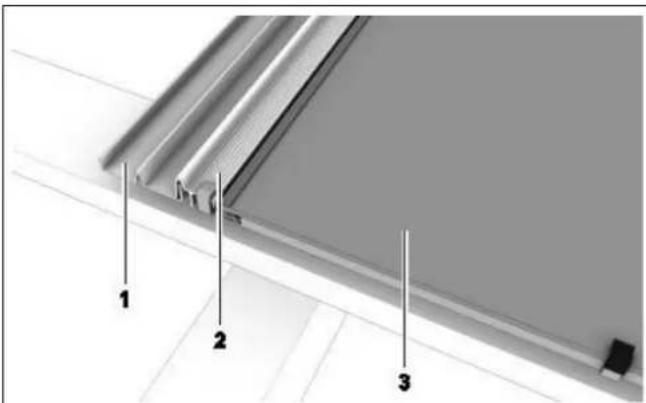
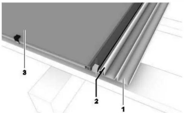
Image 3-8: Flashing profile Left Right
1 Flashing seam
2 Flashing profile
3 Photovoltaic module
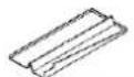
3.5.2 Flashings
Flashings provide a weather proof seam to the roof tiles. They have been designed to be able to accommodate most standard types of roof tiles.
The following flashings are available:
- Flashing side (left/right)
- Flashing side top (left/right)
- Flashing ridge (middle/left/right)
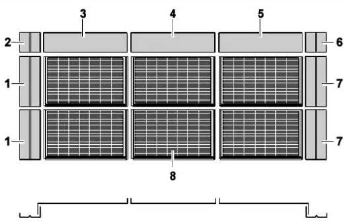
Image 3-9: Mounting of the flashings
| No. | Designation | Lamination size L x W |
| 1 | Flashing side left | (W + 110) × 121 mm |
| 2 | Flashing side top left | 281 × 121 mm |
| 3 | Flashing ridge left | (L + 54) × 281 mm |
| 4 | Flashing ridge middle | (L + 29) × 281 mm |
| 5 | Flashing ridge right | (L + 54) × 279 mm |
| 6 | Flashing side top right | 281 × 121 mm |
| 7 | Flashing side right | (W + 110) × 121 mm |
| 8 | Photovoltaic modules (laying measurements) | (L + 31) × W mm |
Table 3-4: Flashing dimensions –applicable for Landscape and Portrait positioning
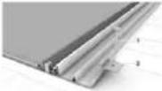
Flashings right/left side
Flashings are attached to the flashing profiles and fastened to the mounting battens by means of sheet grips and nails. The flashings are laid upon the modules' mounting battens and are thus at the same height.
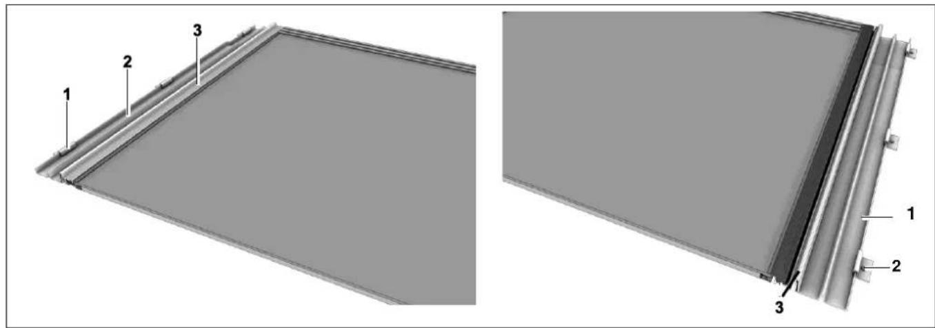
Image 3-10: Flashing side left and right
I Sheet grips with nails
2 Flashing side
3 Flashing profile

TIP
Fasten the sheets with as many sheet grips as deemed necessary but at least:
- Flashing right side/left side: 2 grips
• Flashing topside right/left: I grip
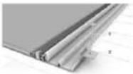
Flashings upper right/left side
The ridge flashings are laid upon the upper side flashings right/left. They have the same width as the side flashings. These flashings can be used with all types of modules.
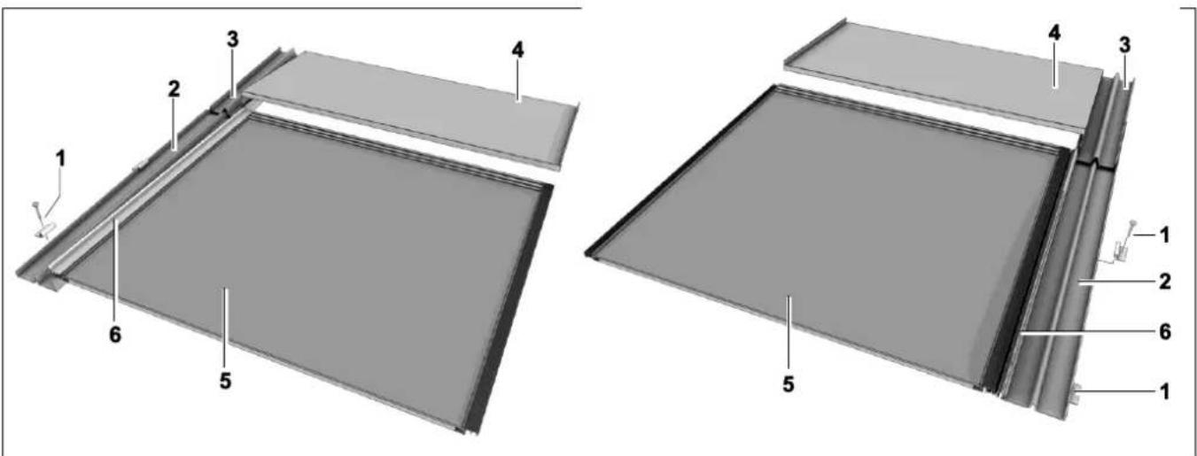
Image 3-11: Flashing top/side left and right
1 Sheet grips with nails
2 Flashing left side
3 Flashing upper left side
4 Flashing ridge left
5 Photovoltaic module
6 Flashing profile left side
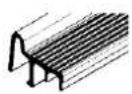
Flashing Ridge
The upper seam consists of individual sheets, each of which is assigned to a module in the upper row.
There are three types of flashings for the upper seam:
- Flashing ridge middle
- Flashing ridge left side
- Flashing ridge right side
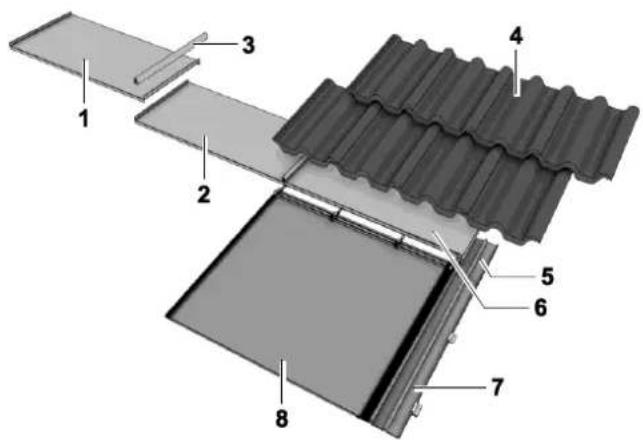
Image 3-12: Flashing ridge
| 1 | Flashing ridge left | 5 | Flashing upper right side |
| 2 | Flashing ridge middle | 6 | Flashing ridge right |
| 3 | Join capping piece | 7 | Flashing right side |
| 4 | Roof tile | 8 | Photovoltaic module |
The ridge flashings left and right have a special construction and lock into the corner flashings and thus ensure a rainproof junction. The ridge flashings are joined at the upturn, or bevel fold, by means of a capping sheet, which also guards against the weather.
3.5.3 Eaves skirting, seam sealing strip and bottom mounting clamps
Lower Seam
The photovoltaic modules can be mounted either directly on the eaves or above the tiles.
For the crossover from the lower array edge to the tiles it is normal to use eaves skirting as for other in-roof fixtures, such as dormer windows (rolled lead sheet 150 mm or Mage flex aluminium roll black 280 mm available as accessories).
The sealing strips (valley sealing strips) are mounted on the eaves skirting in order to close off the roof hollows for small animals and insects.

TIP
It is advisable to lay a 17 mm spacing block underneath the mounting clamp "glass" in the lowest row. This is to prevent the back side of the module from coming into contact with the fold of the mounting clamp by heavy snow load.
4 Mounting
4.1 Tools, Auxiliary Material
→ Have the following tools and other material at hand during the mounting process:
- Carpenter's pencil
- String / chalk line
- Tape measure and measuring stick
- Screwdriver set
- Nails for sheet grips
- Hammer for sheet grip nails
- Level
- Wood saw
• Sheet metal shears and tongs - Knife
- Portable electric screwdriver
- Multimeter
• Ultraviolet-resistant cable ties
• Angle grinder (diamond grinding wheel) for removing tile nibs
4.2 Preliminary Steps
4.2.1 Structural Calculations in Accordance with Eurocode 1 and 5
CAUTION
The design must be checked considering local weather conditions, height of the building and the choice for landscape or portrait module orientation, in order to prevent severe damage to the photovoltaic system and to the roof structure using Eurocode I and 5 (DIN 1055 and DIN 1052 for Germany: Règles NV 65 for France; NTC 2008 for Italy)
In the following tables it can be seen what load the PV system can withstand. Together with Annex I a good indication can be obtained what design is suitable for the chosen site and system angle. In case of a critical situation or an extreme building design or location it is best to make use of a consultant specialised in static calculations.
Scheuten offers the possibility to position the Integra modules portrait in addition to landscape. To enable portrait, extra broad and longer clamps, are designed. An important factor in case of suction is the quality of the decking and the ability to withstand the high loads the Integra system can bear. As already shown in images 3-6 and 3-7 the modules can be mounted on horizontal or vertical battens. In case of high loads it can be needed to increase the number of glass clamps.
| P6-54 Integra Vitro Landscape | 2 glass clamps per module (pitch 507 mm) | 3 glass clamps per module (pitch 380 mm) | ||
| Suction (Wind) | Pressure Load (Snow/Wind) | Suction (Wind) | Pressure Load (Snow/Wind) | |
| Horizontal mounting battens (image 3.6A) | 1900 Pa | 2400 N/m^2 | 2200 Pa | 3300 N/m^2 |
| Vertical mounting battens (image 3.6B) | 1900 Pa | 2400 N/m^2 | 2400 Pa | 3300 N/m^2 |
Table 4-1: Maximum Load as a function of roof design for Landscape oriented modules
| P6-54 Integra Vitro Portrait | 2 glass clamps “Portrait” per module (pitch 341 mm) | |
| Suction (Wind) | Pressure Load (Snow/Wind) | |
| Horizontal mounting battens (image 3.7A) | 1500 Pa | 3200 N/m^2 |
| Vertical mounting battens (image 3.7B) | 2400 Pa | 4500 N/m^2 |
Table 4-2: Maximum Load as a function of roof design for Portrait oriented modules
In the tables above the maximum load is calculated and given with an accuracy of ±100 N/m^2 . The pressure of the snow exerted onto the PV system is given for a slope of 30^ , being the worst case if the snow is not restricted in sliding off.
It can be seen that the load the modules can withstand (IEC 61215 certification: 5400 Pa) is not the determining factor, but clamps, screws or decking.
4.2.2 PV System Size
Before a decision is taken on the orientation of the modules it is needed to determine how the desired number of modules fit on the roof. It should be realized that this not only depends on the module size but also on the number of modules (overlap) and the size of the flashings.

TIP
When calculating the size of the grid, do not forget the overlapping frame profiles.
→ Calculate the size of the grid:
MS Integra Vitro Landscape and Portrait
- Grid size horizontal: R hor [mm] = Unframed module Length [mm] + 34 mm (overlapping frame profiles)
- Grid size vertical: R _ver [mm] = Unframed module Width [mm]
= 988 mm (Landscape)
= 1488 mm (Portrait)
$$ = 1 4 8 8 + 3 4 = 1 5 2 2 \mathrm{mm} (\text { Landscape }) $$
$$ = 9 8 8 + 3 4 = 1 0 2 2 \mathrm{mm} (\text { Portrait }) $$
→ Calculate the size of the PV System:

TIP
The pitch as given above can be slightly smaller (5 mm) or larger (5 mm) by varying the frame overlap if needed
I. Multiply the grid size by the corresponding number of module columns or module rows:
- PV System width [mm] = R hor [mm] x number of module columns
-
PV System height [mm] = R _ver [mm] x number of module rows
-
Include the outer frame profiles, as they have no further overlapping elements:
-
PV System width [mm] + 30 mm (15 mm right and left)
-
PV System height [mm] + 30 mm (top)
-
Include the flashings, as the case may be.
4.2.3 Define the substructure
Based on the structural requirements, snow and wind load, and the desired orientation of the modules the roof structure under the PV system must be built up.
I. Determine the module orientation, either from aesthetics and/or the roof dimensions and required PV system size
2. Determine the required system strength.
3. Compare the required system strength with the data in tables 4-1 and 4-2, and determine whether the design is restricted.
4. Determine the orientation of the mounting battens on the basis of the roof structure and required system height and strength.
5. Determine the number of clamps on the basis of table 4-1 or 4-2.
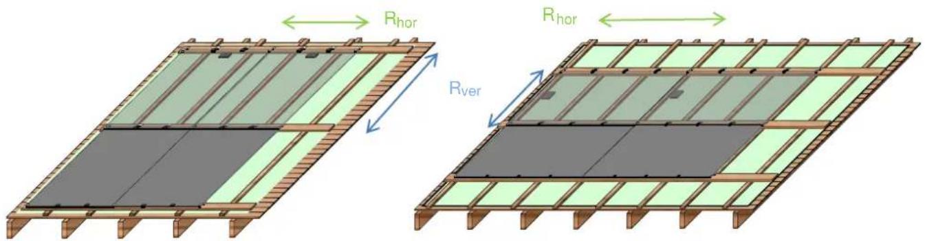
Image 4-1: Horizontal Mounting Battens
A: Integra Vitro Portrait with 2 Glass Clamps "Portrait"
B: Integra Vitro Landscape with 3 standard Glass Clamps
Images 4-1 A and B show mounting with horizontal Integra battens. The substructure starts with the dedicated roof foil. On top the counter battens are nailed. It is strongly advised to align the counter battens with the modules, in order to keep always enough distance between the j-box and the wooden substructure. For a proper strength of the substructure, a maximal pitch of 600 mm is needed. For Portrait this preferably results in two vertical mounting battens at positions 14 *hor and 34 *Rhor under each module; a pitch of 511 mm. For Landscape this leads to three counter battens per module at 0, 1/3 and 2/3*Rhor under each module; a pitch of 507 mm.
The mounting battens are of course positioned at bottom and top of a module at a distance of Rver and must be screwed at each crossing with a counter batten. See for the position of the battens also table 4-3.
CAUTION
The counter battens, min. 34 x 22 (WxH), must be screwed in the decking (2 SS full-thread pan head screws 4.5 x 40 mm), additionally to nailing, to prevent the battens to be torn out of the decking, at even moderate suction loads. This must be done near the points, where the Integra battens are screwed on the counter battens.
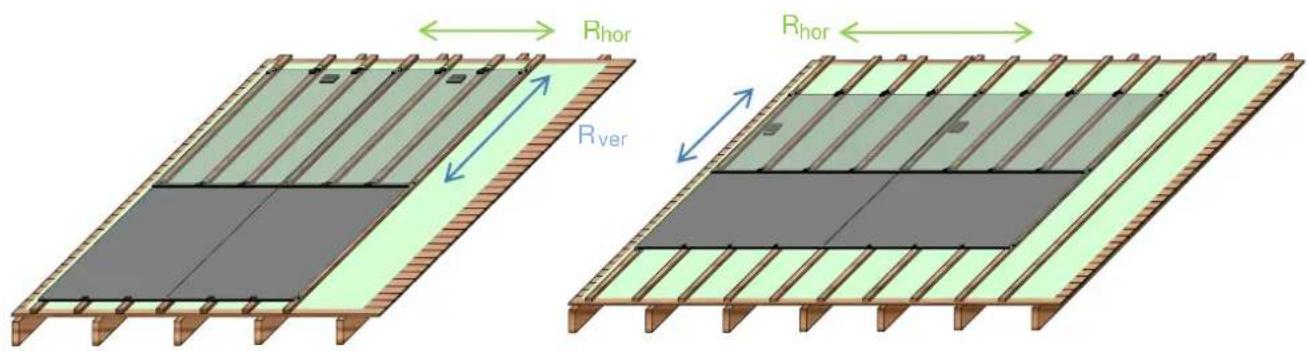
Image 4-2: Vertical Mounting Battens
A: Integra Vitro Portrait with 2 Glass Clamps "Portrait"
B: Integra Vitro Landscape 3 standard Glass Clamps
Images 4-2A and B show mounting with vertical battens. This is a good option in case the height of the PV system has to be low, or, for portrait, the loads are high. The substructure also starts with the dedicated roof foil. On top, the mounting battens are screwed. The battens must be aligned with the modules, with a batten at the left and right of the module, and the others for the glass clamps.
For Portrait this results in a similar position for the vertical Integra battens as for the counter battens in image 4-1A; a pitch of 341 mm (1/3*Rhor). For Landscape this leads a pitch of 507 mm (1/3*Rhor) in case of two glass clamps and a pitch of 380 mm (1/4*Rhor) for three glass clamps.
| Module Orientation | Mounting Batten | Pitch Rhor | Pitch Rver | Counter Battens mm | Mounting Battens (mm) | |
| Horizontal | Vertical | |||||
| Portrait PG-54 | Horizontal | 1022 mm | 1488 mm | 255, 766, 1277, 1788, ....*1⁄4, 3⁄4, 5/4, 7/4 ... ...x Rhor | 0, 1022, 2044, ....**0, 1, 2, ... x Rver | |
| Landscape PG-54 | Horizontal | 1522 mm | 988 mm | 0, 507, 1015, 1522, 2029,.....*0, 1/3, 2/3, 1, 4/3 ...x Rhor | 0, 1522, 3044,.....**0, 1, 2, ... x Rver | |
| Portrait PG-54 | Vertical | 1022 mm | 1488 mm | 0, 341, 682, 1022, 1363....**0, 1/3, 2/3, 1, 4/3 ...x Rhor | ||
| Landscape PG-542 clamps3 clamps | Vertical | 1522 mm | 988 mm | 0, 507, 1014, 1522, 2029, ....*0, 1/3, 2/3, 1, 4/3 ...x Rhor0, 380, 761, 1141, 1522, .....*0, 1⁄4, 1⁄2, 3⁄4, 1, 5/4, ...x Rhor | ||
Table 4-3: Position of the battens referred to the low end or right-hand side of the first batten
recommended prescribed

WARNING
→ The indicated dimensions of the battens and screws must be followed to meet the structural requirements:
Counter battens min. 34 x 22 mm (WxH) nailed (pitch 500 mm) and additionally screwed near crossings with mounting battens:
2 SS full-thread pan head screws 4.5 x 40 mm
Horizontal mounting battens min. 120x28 mm (WxH) On counter battens using SS full-thread pan head screws 5 x 80 mm
Vertical mounting battens min. 50 x 34 mm (WxH) On decking using SS full-thread pan head screws 5 x 55 mm
→ The battens must be softwood construction grade timber.
→ Touching of the junction-box to the under construction should be prevented as the J-box might be hot under operation.
Under high snow or wind load the module can touch the under construction.
→ Prevent sharp points to touch the module.

TIP
Photovoltaic modules become warm due to absorption of sunlight.
High module temperatures lessen the system's power output and may give a significant heat load on the roof substructure.
- Proper ventilation of the modules is needed to maximize the power output and minimize the heat load on the roof.
→ Plan for a generous horizontal air gap for ventilating the modules (if possible with counter-battens as with a normal roof).
→ Do not obstruct the vertical heat-flow
4.2.4 Prepare the substructure
- Fasten the substructure battens with ample fasteners directly on to the roof, at the size and position determined in 4.2.3.
- Align the substructure with the position of the mounting clamps for the photovoltaic modules (cf. grid plan), see image 4-1 and 4-2.
- Close off the open cross cut between the eaves-side battens with a protective screen against birds, etc.
- If possible, convert the roof ridge into an aeration ridge in order to allow a proper air flow for cooling the modules.
- Use eaves-side skirting (lead roll or Mage flex ^8 strip) for the crossover from the lower edge of the system to the tiles.
CAUTION
It must be possible, where necessary (e.g. repair work), to be able to remove the modules from the row!
→ Fasten further rows of mounting clamps leaving space to the modules (cf. image 4-3).
For Landscape leave a space of 15 mm (x)
For Portrait leave a space of 30 mm (y)
→ When removing, slide the modules upwards until they are free of the lower clamps.
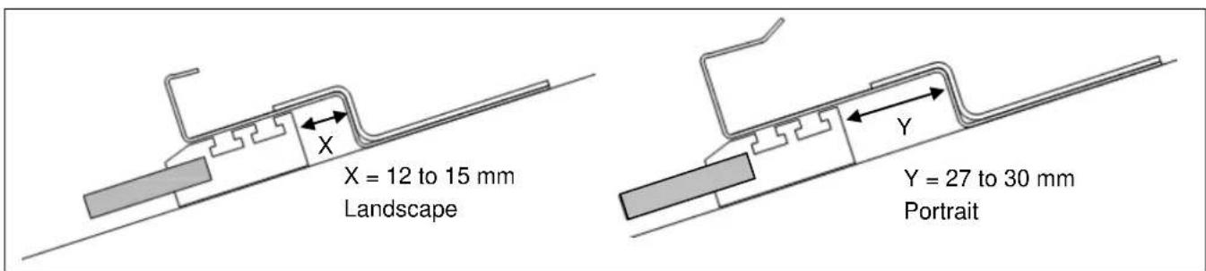
Image 4-3: Space needed to be able to remove the module, x=12-15 mm for Landscape, 27-30 mm for Portrait
4.3 In-roof mounting of the PV-system
√ Load-bearing capacity of the roof construction has been tested.
√ Roof substructure has been constructed and the connections to the roof tiles prepared.
√ Fire resistant and roofing underlay is placed.
√ The position of the entire photovoltaic system has been measured on the roof.
√ Corner points have been marked.
√ A grid plan has been drafted (section 4.2) and the wiring (section 4.4) of the individual photovoltaic modules has been plotted.
√ Inverter cable has been laid, the circuit cables prepared (section 4.4) and the Integra modules on site.
√ Safety regulations are known.
4.3.1 Installing the Photovoltaic Modules
The photovoltaic modules can be mounted either directly on the eaves or in roofs where rows of tiles are present between gutter and PV system.
Mounting on the Eaves
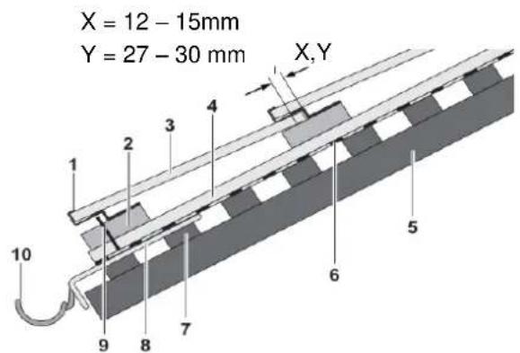
Image 4-4: Roof integration position directly at eaves edge in case of horizontal mounting battens
1 Mounting clamps Landscape or Portrait version
2 Mounting batten 120 x 28 mm
3 Photovoltaic module
4 Counter batten 34 x 22 mm
5 Rafter
X.Y Spacing required to be able remove the module X: Landscape Y: Portrait
6 Underlay
7 Roof furring strip
8 Eaves flashing
9 Protective screen
10 Gutter
For vertical mounting battens, (50 x 34 mm) the built-up is similar.
Mounting above the Tiles
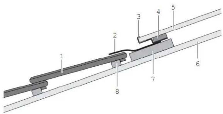
Image 4-5: Roof eaves integration with tiles in case of horizontal
1 Roof tile
2 Eaves-side skirting
3 Mounting clamps Landscape or Portrait version
4 Channel sealing tape 20 x 60mm
5 Photovoltaic module
6 Counter batten
7 Mounting batten 120 x 28 mm (min.)
8 Tile batten
For vertical mounting battens, (50 x 34 mm) the built-up is similar.
CAUTION
Drainage at the Eaves Skirting
Prevent water damage.
When determining the spacing between mounting batten and roof tile make sure of the required minimum slope ( 10^9 ) to ensure that water can drain off.
IA. Mounting on the eaves: attach the protective screen against birds.
IB. Mounting above the tiles: fasten the eaves-side skirting on the mounting batten
2. Fasten the first and the last mounting clamp "frame" (Portrait or Landscape) of the first module on to the lowest mounting batten using two SS full-thread pan head screws (4.5 x 35) per clamp.
3. Line up the two mounting clamps with the chalk line and fasten them.
4. Align the other lowest row mounting "glass" and "frame" clamps (Portrait or Landscape), according to the grid plan and fasten them.
5. Test the clamps for stability.
68. Mounting above the tiles: apply the channel sealing tape.
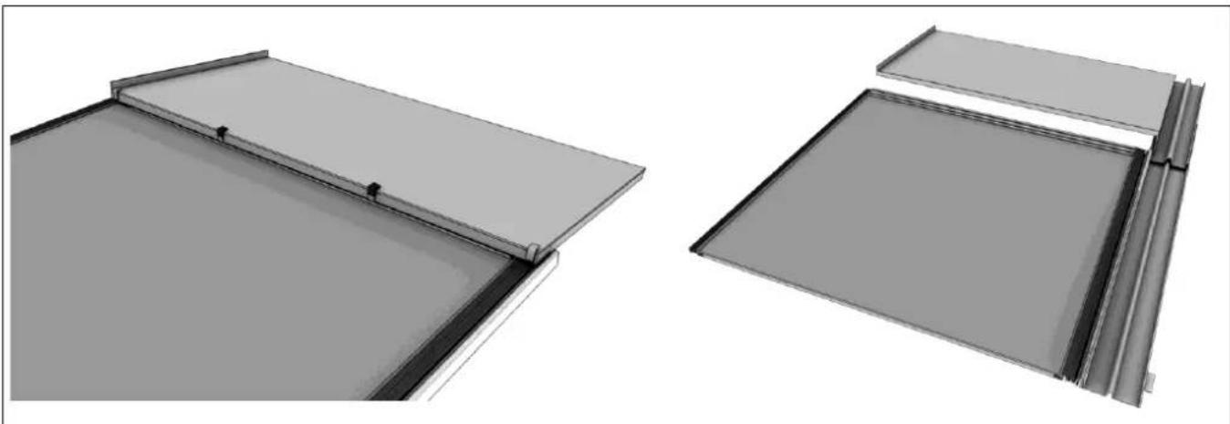
Mounting the Modules
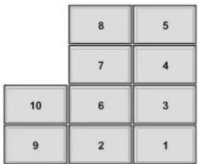
Image 4-6: Module installation order
CAUTION
DO NOT STEP ON THE MODULES!
Do not install in the Wrong Direction!
→ Start installing from the bottom up!
→ Due to the lateral overlapping of the individual frame pieces only lay the modules from the right to the left.
→ Make sure that the cables are not pressed between the modules and the under construction.
TIP
The modules can also be installed column by column, so that the roof remains accessible for the installation of further rows.
→ Make sure that the inverter cables and the circuit connecting cables have been installed before installing the modules. (see 4.4)
→ Lead the cables to the left before laying the module to allow access to the connectors.
I. Lay the first photovoltaic module (1 in image 4-6) in the mounting clamps.
Mind that the drainage channels of the frame profile are on the left and the open lamination edge on the bottom.
2. Lay the flashing profiles and if necessary flashings on the right with the frame profiles in the clamp.
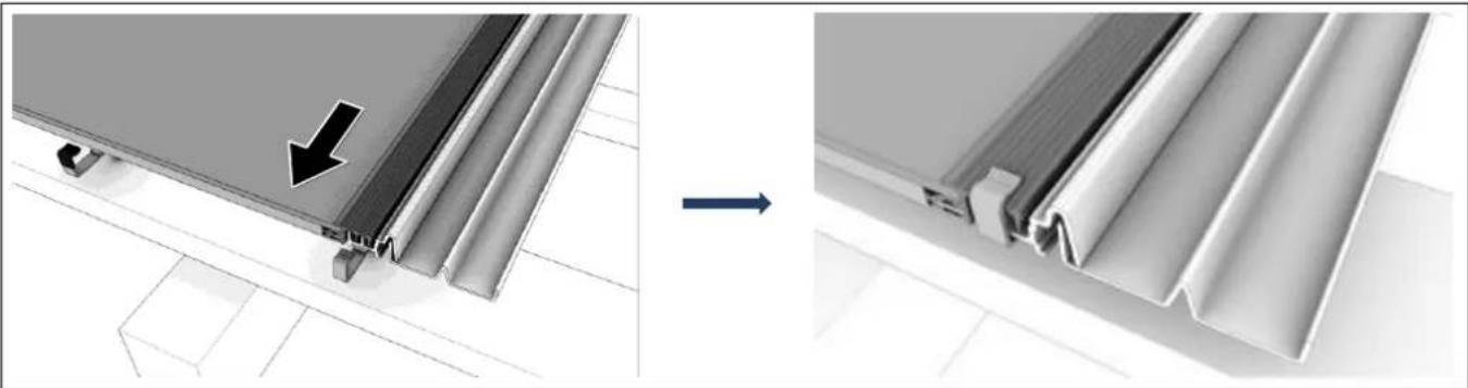
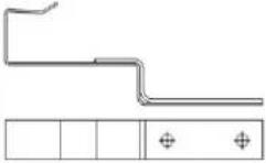
natural_image
Diagram showing structural change from a panel with an arrow to a final panel with a V-shaped cutout (no text or symbols)Image 4-7: Mounting the first module
- Make sure that the mounting clamp "frame" fits exactly into the slots of the frame profile (fixed point).
| ! TIP |
| Flashing profiles and flashings should be installed with their respective row of modules! |
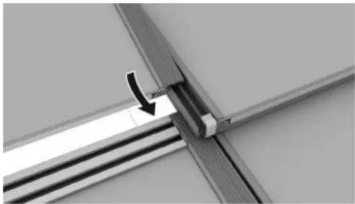
- Take another module and take the connector from the first module and put it into the connecting socket of the next module.
- Slide the frame profile of the next module into that of the first one.
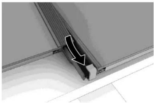
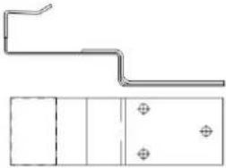
natural_image
Close-up of a structural joint or panel with a white arrow pointing to a specific component (no text or symbols visible)Image 4-8: Mounting a further module
- Determine the position of the second row of mounting clamps. Mind to keep 15 mm (Landscape) or 30 mm (Portrait) space to the upper edge of the module.
- Fasten the second row of mounting clamps to the rafter and test for stability.
| WARNING |
| The mounting clamps and horizontal battens must be level (parallel to the gutter and ridge) and equidistant ( R_ver )Vertical mounting battens must be at an exact angle of 90^ → A good measurement of R_ver , vertical distance between the mounting clamps.→ Equidistant “Profile” clamps at exactly R_hor are crucial for the correct installation of the module array and the resultant optical appearance. |
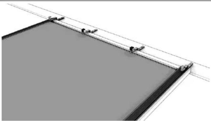
natural_image
Architectural or structural diagram showing a rectangular frame with diagonal lines and small protrusions, no visible text or symbols.Image 4-9: Fastening mounting clamps for further rows
- Lay the first photovoltaic module in the mounting clamps in the second row to the right. Mind that the notches of the frame profile, which are facing upwards, are on the left side.
- Take another module and take the connector from the first module from the second row and put it into the connector of the next module.
- Slide the frame profile of the next module into that of the first one.
natural_image
Close-up of a metal bracket with a black arrow pointing to a vertical component, no visible text or symbolsImage 4-10: Mounting modules
II. Mount further rows of mounting clamps and photovoltaic modules as described above.
12. Connect flashing profiles and if necessary flashings to the frame profiles on the left array edge. (see also 4.3.1)
13. Fasten the top row of the modules
4.3.2 Roof Seams

TIP
Roof seams are necessary when the modules do not completely cover the roof.
Roof Seams left and right
I. Connect flashing profiles right and left to the frame profiles at the array edge.
2. Connect flashings to the flashing profiles.
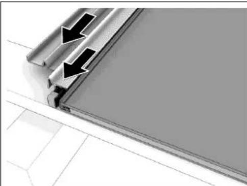
natural_image
Close-up of a metallic panel corner with two black arrows indicating direction, no text or symbols present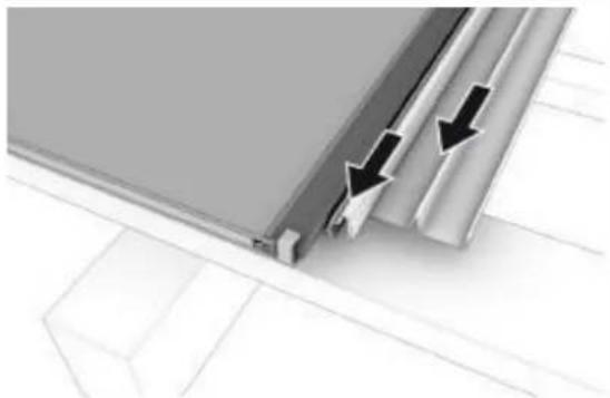
natural_image
Close-up of a metallic panel edge with black arrows indicating direction, no text or symbols presentImage 4-11: Flashing profile and flashing side, left and right
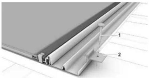
natural_image
Technical diagram of a structural panel assembly with labeled components (no text or symbols present)Image 4-12: Fastening flashing with sheet grips
1 Nail
2 Sheet grip
- Fasten the outer upturn of the flashings with sheet grips and nails.
In case of vertical mounting battens, the tile battens can be used to fasten the sheet grips - Using a diamond wheel angle grinder to remove the right or, as the case may be, the left nib of the tile that is to lie upon the flashing.
- Cover the rest of the roof with tiles.

TIP
Fasten the side sheets with sheet grips according to need but at least:
- Flashing on the right or left side: 2 pieces.
• Flashing on the right or left corner: I piece.
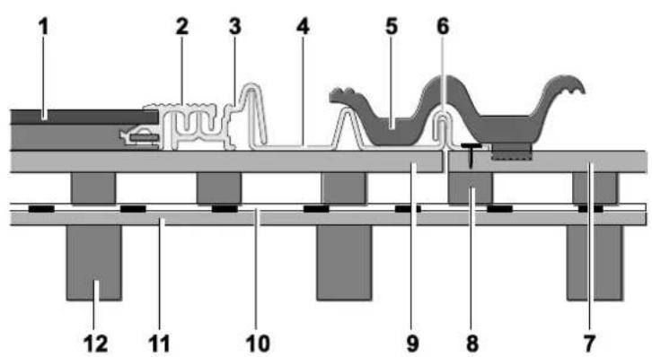
Image 4-13: Roof integration on a tiled roof with horizontal mounting battens (right)
1 Scheuten Integra Module
2 SOLRIF ^® D profile frame
3 Flashing profile right
4 Flashing side right
5 Roof tile
6 Sheet grip
7 Tile batten
8 Counter batten
9 Mounting batten 120 x 28 mm
10 Underlay
II Decking
12 Rafter
Roof Seam Top
- Fasten flashing side/top/right.
- Fasten the uppermost row of modules with mounting clamps "profile" and "glass", as for the other rows, to the mounting batten and test for stability.
natural_image
Two technical diagrams showing structural components with no visible text or symbolsImage 4-14: Flashing ridge; middle/right
-
Fit the flashings into the last row of mounting clamps:
-
Fasten flashing ridge/left above the uppermost left module. Make sure that the flashing overlaps flashing side/top/left.
- Fasten flashing ridge/right above the uppermost right module. Make sure that the flashing overlaps flashing side/top/right.
-
Fasten flashing ridge/middle above the centre modules.
-
Connect the individual flashings with a join capping piece profile (cf. Image 3-121213, p. 15).
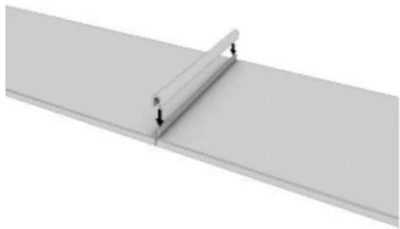
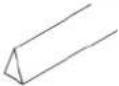
natural_image
Pure diagram of a beam supported by two vertical supports, with no text or symbols present.Image 4-15: Placing the join capping piece profile
- Cover the rest of the roof surface with tiles.
Seams without Flashings
I. Fasten the top row of the modules to the top mounting batten, or the end of the vertical battens by means of mounting clamps "profile" and test for stability.
2. Fasten sealing tape (rolled sheet lead or Mage flex strip) to the mounting batten(s).
3. Cover the upper array edge directly with a ridge tile.
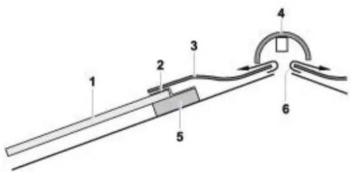
Image 4-16: Integration without flashings
1 Scheuten Integra module
2 Mounting clamp
3 Sealing tape
4 Ridge tile
5 Mounting batten
6 Ventilation ridge
4.4 Wiring
TIP
Only ultraviolet and heat resistant solar cables rated for 1000 V or higher are permissible for wiring photovoltaic systems.
Wiring and potential equalization (4.5) must be prepared before starting mounting the modules!
- Connect the inverter cable to the first module or to the lowest module of the circuit.
- Connect the modules in horizontal circuits (male and female connectors).
- Connect the module circuits by means of the circuit connecting cable (not included in the delivery).
- Decide on the necessity of lightning protection and potential equalization measures.
flowchart
graph TD
    A["+"] --> B["1"]
    B --> C["3"]
    C --> D["2"]
    D --> E["4"]
    E --> F["Bottom"]
    F --> G["Bottom"]
    G --> H["Bottom"]
    H --> I["Bottom"]
    I --> J["Bottom"]
    J --> K["Bottom"]
    K --> L["Bottom"]
    L --> M["Bottom"]
    M --> N["Bottom"]
    N --> O["Bottom"]
    O --> P["Bottom"]
    P --> Q["Bottom"]
    Q --> R["Bottom"]
    R --> S["Bottom"]
    S --> T["Bottom"]
    T --> U["Bottom"]
    U --> V["Bottom"]
    V --> W["Bottom"]
    W --> X["Bottom"]
    X --> Y["Bottom"]
    Y --> Z["Bottom"]
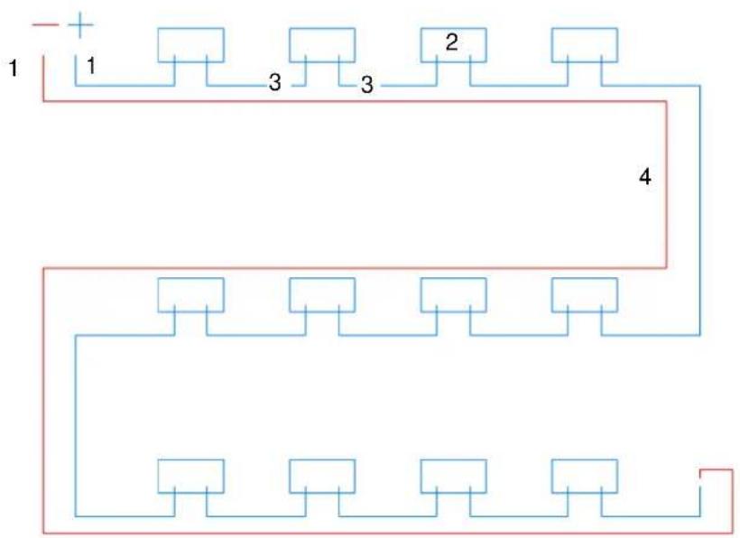
Image 4-17: Correct lay-out of cables – image is a guide to the eye and doesn't refer to the positioning of the modules
1 Cable from the circuit to the inverter
2 Junction-Box
3 Module cable with connector
4 Circuit connecting cable
4.5 Potential Equalization and Lightning Protection
CAUTION
Voltage via Residual Current or Capacitive Charging
Electric shock upon contact with metal parts is possible and can result in damage or injury.
→ Prevent personal injury by correctly conducting potential equalization.

TIP
It is generally recommended to ground the PV System and to link it to potential equalization, it is usually mandatory in case of:
- Transformerless inverter
• Existent lightning protection system with proper distancing
→ Establish potential equalization in accordance with IEC 60364-7-712 or with the corresponding national regulations as protection against electric shock.
The potential equalization should be done using one of the pre-drilled holes in the top part of the frame. Connection can be best made to the grounding hole using M3 nuts and bolts with a toothed lock washer connected to a cable of at least 6mm ^2 . Between the PV-System and the building 16mm ^2 is recommended.
The potential equalization has to be connected with the grounding system of the building.
Potential equalization and lighting protections is ruled by national standards and generally accepted codes of practice, which prevail over this statement. If the applicable regulations appear to be in conflict with the statements made here pls. contact your sales office.
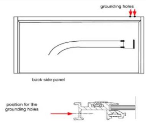
Image 4-18: Holes for potential equalization
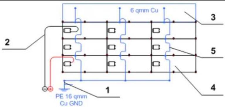
Image 4-19: Recommended potential equalization
- image is a guide to the eye and doesn't refer to the positioning of the modules
1 Grounding 16 mm² Cu
2 String cable to the inverter
3 Ridge flashings
4 Scheuten module
5 Potential equalization 6 mm² Cu at the modules
Lightning and Overvoltage Protection
CAUTION
Damage due to faulty lightning and overvoltage protection!
Damage to the photovoltaic module array, to the inverter and the building due to faulty exterior or interior lightning protection is possible.
→ Properly installed lightning protection in accordance with EN 62305 prevents damage due to overvoltage.
TIP
Lightning or overvoltage protection may be necessary instead of potential equalization:
- Negligible safety distance between PV System and lightning protection system.
- On public buildings.
→ Connect the PV System to the exterior lightning protection system of the building.
→ Establish interior lightning protection as AC/DC overvoltage protection.
→ Observe related national and perhaps regional regulations.
5 Connecting to the Inverter
CAUTION
High Voltage!
Mortal danger due to DC of up to 1000 volts in the string cables of the modules. This voltage is present even at very low irradiance (twilight).
Connecting the photovoltaic modules to the inverter should be carried out only by a qualified electrician.
→ Follow the safety regulations and the corresponding operating guidelines of the inverter.
TIP
Proper system configuration for optimal solar energy production from each module.
• The system configuration has essential influence on the energy yield of the photovoltaic system.
→ Follow the layout criteria for the inverters and the guidelines of the module manufacturer for an optimal combination with the inverters.
6 Dismounting
√ The photovoltaic system has zero-potential.
→ Dismounting is conducted in reverse order to mounting.
7 Control
→ Before initial operation of the photovoltaic system test the following points.

DANGER
High voltage! Mortal danger!
→ Follow safety regulations.
→ Work on voltage conducting parts should be carried out only by a qualified electrician.
| Control | Date/Signature |
| Measure string open circuit voltage and compare with the expected value (module number X open circuit voltage), cf. module data sheet | |
| Roof closed?All roof tiles in their proper place? | |
| All cables attached?No contact with roof surface? | |
| All outer connections carefully sealed? |
Table 7-1: Control checklist
8 Disposal
→ Scheuten Solar is member of PV Cycle. In the framework of this European organization, Scheuten solar modules will be recycled for free. Please contact your local sales office for information
→ Follow strictly the national and regional regulations when disposing of or recycling the photovoltaic system or its components.
9 Parts List
| Picture | Description | MS Integra Vitro Landscape | MS Integra Vitro Portrait | ||
| ARTICLE NUMBER | INTERN | EXTERN | INTERN | EXTERN | |
 | Mounting clamp "Profile", black | BM000158 | 05653 | ||
 | Mounting clamp "Profile Portrait" | BM000194 | 15898 | ||
 | Mounting clamp "Glass", black | BM000159 | 05654 | ||
 | Mounting clamp "Glass Portrait", black | BM000195 | 15855 | ||
Table 9-1: 4 types of mounting clamps are required for the installation of the Integra system.
| Picture | Description | Dimensions | Article number | |
| INTERN | EXTERN | |||
 | Screw for clampSS full-thread pan head screw (4.5 x 35) | 4.5 x 35 mm, pan head | BMOD0110 | 06545 |
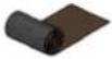 | Rolled aluminium, Mage flex, black pleated alu - 280 mm | 28 cm | BMOD0114 | 06827 |
 | Sealing tape | 1 m x 30 mm x 40 mm | BMOD0114 | 06736 |
 | Protective profile for flashings top | 0.28 m | BMOD0112 | 06801 |
 | Fixings for flashings (nr. 2)Sheet grips | BMOD0116 | 05483 | |
 | Nail DIN IIGO for fixings (nr. 1) | 2.5 x 25 mm | BMOD0117 | V03748 |
Table 9-2: All accessories required to complete the Integra Vitro system. These materials are not related to the module type and therefore are identical for both Multisol Integra Vitro Landscape as well as Multisol Integra Vitro Portrait
9.1 Accessories MS Integra Vitro
| Picture | Description | Article number Integra Vitro | Article number Integra Vitro | ||
| LANDSCAPE | PORTRAIT | ||||
| INTERN | EXTERN | INTERN | EXTERN | ||
 | Flashing profile left | BM00016I | 14719L | BM000185 | 15211L |
 | Flashing profile right | BM000160 | 14724L | BM000186 | 15212L |
 | Flashing side left | BM000168 | 14946L | BM000190 | 15264L |
 | Flashing side right | BM000167 | 14947L | BM000191 | 15265L |
 | Flashing side top left | BM000165 | 06852L | BM000165 | 06852L |
 | Flashing side top right | BM000166 | 06853L | BM000166 | 06853L |
 | Flashing ridge left | BM000162 | 14943L | BM000188 | 15261L |
 | Flashing ridge right | BM000163 | 14944L | BM000189 | 15262L |
 | Flashing ridge middle | BM000164 | 14945L | BM000187 | 15263L |
Table 9-3: All flashings required to complete the Integra Vitro system.
A distinction is made between right and left and between the different modules types.