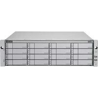
VESS J2600SS - NAS Promise Technology - Free user manual and instructions
Find the device manual for free VESS J2600SS Promise Technology in PDF.


| Product Type | Network Attached Storage (NAS) |
| Model | VESS J2600SS |
| Brand | Promise Technology |
| Form Factor | 2U rackmount |
| Dimensions (H x W x D) | 88.4 x 447 x 660 mm |
| Weight | Approximately 22 kg (without drives) |
| Power Supply | Dual redundant hot-swappable 600W power supplies |
| Main Functions | Data storage, file sharing (NFS, CIFS, AFP), iSCSI, RAID levels 0,1,5,6,10, JBOD, snapshot, replication, virtualization support |
| Drive Bays | 12 hot-swappable 3.5" or 2.5" SATA/SAS drives |
| Network Connectivity | 4 x 1GbE RJ-45 ports, optional 10GbE |
| Management | Web-based GUI, CLI, SNMP, email alerts |
| Maintenance and Cleaning | Regular firmware updates, disk health monitoring via S.M.A.R.T., clean air filters quarterly, avoid dust and moisture |
| Safety | Overvoltage protection, temperature monitoring, redundant cooling fans, lockable drive trays |
| Spare Parts and Repairability | Hot-swappable hard drives, power supplies, and fans; memory modules and controller battery are replaceable |
| General Information | Supports virtualization (VMware, Hyper-V), integrates with Active Directory, includes backup software |
Frequently Asked Questions - VESS J2600SS Promise Technology
User questions about VESS J2600SS Promise Technology
0 question about this device. Answer the ones you know or ask your own.
Ask a new question about this device
Download the instructions for your NAS in PDF format for free! Find your manual VESS J2600SS - Promise Technology and take your electronic device back in hand. On this page are published all the documents necessary for the use of your device. VESS J2600SS by Promise Technology.
USER MANUAL VESS J2600SS Promise Technology
Vess R2000 Series Product Manual
Version 2.2

Warning
This is A-Class A product. In a domestic environment this product may cause radio interference in which case the user may be required to take adequate measures.

Warning
The electronic components within the Vess enclosure are sensitive to damage from Electro-Static Discharge (ESD). Observe appropriate precautions at all times when handling the Vess or its subassemblies.

Warning
Turn off the power and disconnect the power cord before servicing this device.
Also included are four levels of notices:

Warning
A Warning notifies you of probable equipment damage or loss of data, or the possibility of physical injury, and how to avoid them.

Caution
A Caution informs you of possible equipment damage or loss of data and how to avoid them.

Important
An Important message calls attention to an essential step or point required to complete a task, including things often missed.

Note
A Note provides helpful information such as hints or alternative ways of doing a task.
Introduction 1
ABOUT THIS MANUAL 2
Vess R2600 Overview 5
NOTABLE FEATURES IN THE VESS R2600 6
PERFECTREBUILD™ 6
ADVANCED BATTERY FLASH BACKUP 6
ONLINE LUN CLONE 6
ARCHITECTURAL DESCRIPTION 7
Vess R2000 Series Model Line-up 7
Vess J2000 Series Model Line-up 7
SPECIFICATIONS 8
HARDWARE 11
FRONT PANEL HARDWARE 11
FRONT PANEL LEDs 13
REAR PANEL HARDWARE 15
REAR PANEL LEDs 21
FIBRE CHANNEL PORT LED BEHAVIOR (Vess R2600FI CONTROLLER) 22
SYSTEM MANAGEMENT 23
MANAGEMENT INTERFACES 23
ADVANCED STORAGE FEATURES 24
BACKGROUND ACTIVITIES 24
PERFECTRAID FEATURES 25
SUPPORTED BROWSERS 25
FIBRE CHANNEL WITH JBOD EXPANSION 45
FIBRE CHANNEL SAN - No SINGLE POINT OF FAILURE 47
FC SAN NSPF DATA PATH 47
FC SAN NSPF MANAGEMENT PATH 49
JBOD EXPANSION 49
ISCSI STORAGE AREA NETWORK (SAN) 51
ISCSI SAN DATA PATH 51
MANAGEMENT PATH 52
ISCSI DIRECT ATTACHED STORAGE (DAS) 54
DATA PATH 54
MANAGEMENT PATH 54
ISCSI WITH JBOD EXPANSION 56
MAKING SERIAL CABLE CONNECTIONS 58
CONNECTING THE POWER 59
LED BEHAVIOR 60
FRONT LED BEHAVIOR AFTER BOOT UP 61
DRIVE STATUS LED BEHAVIOR AFTER BOOT UP62
REAR PANEL PSU & COOLING UNIT LEDs 63
CONTROLLER LEDs 64
CONTROLLER LED BEHAVIOR 65
System Setup 66
SETTING-UP THE SERIAL CONNECTION 67
ABOUT IP ADDRESSES 68
DEFAULT IP ADDRESSES 68
CHOOSING DHCP OR A STATIC IP ADDRESS 69
ACCESSING THE MAC ADDRESS IN THE CLI 70
ACCESSING THE MAC ADDRESS IN THE CLU 71
SETTING-UP WITH THE CLI 72
MAKING SUBSYSTEM DATE AND TIME SETTINGS (CLI) 72
VIRTUAL MANAGEMENT PORT SETTINGS (CLI) 73
MAKING VIRTUAL MANAGEMENT PORT SETTINGS - AUTOMATICALLY (CLI) 73
MAKING VIRTUAL MANAGEMENT PORT SETTINGS - MANUALLY UNDER IPv4 (CLI) 74
MAKING VIRTUAL MANAGEMENT PORT SETTINGS - MANUALLY UNDER IPv6 (CLI) 75
MAINTENANCE MODE SETTINGS (CLI) 76
MAKING MAINTENANCE MODE SETTINGS - AUTOMATICALLY (CLI) 76
MAKING MAINTENANCE MODE SETTINGS - MANUALLY UNDER IPv4 (CLI) 78
MAKING MAINTENANCE MODE SETTINGS - MANUALLY UNDER IPv6 (CLI) 80
SETTING UP WITH WEBPAM PROE 82
LOGGING INTO WEBPAM PROE 82
CREATING DISK ARRAYS AND LOGICAL DRIVES 85
AUTOMATIC CONFIGURATION 86
ENABLING LUN MAPPING AND MASKING 90
LOGGING OUT OF WEBPAM PROE 91
USING WEBPAM PROE OVER THE INTERNET91
WebPAM PROe - System Configuration 92
LOGGING INTO WEBPAM PROE 93
CHOOSING THE DISPLAY LANGUAGE 94
PERUSING THE INTERFACE 95
LOGGING OUT OF WEBPAM PROE 97
VIEWING THE STORAGE NETWORK 98
LOGGING ONTO A SUBSYSTEM 98
FILTERING THE SUBSYSTEM LIST 99
REFRESHING THE LIST 99
MANAGING SUBSYSTEMS 100
VIEWING SUBSYSTEM INFORMATION 101
MAKING SUBSYSTEM SETTINGS 102
LOCKING OR UNLOCKING THE SUBSYSTEM 102
SETTING THE LOCK 102
RESETTING THE LOCK 103
RELEASING THE LOCK 103
RELEASING A LOCK SET BY ANOTHER USER 103
RESTORING FACTORY DEFAULT SETTINGS 104
CLEARING STATISTICS 105
SAVING A SERVICE REPORT 106
IMPORTING A CONFIGURATION SCRIPT 108
EXPORTING A CONFIGURATION SCRIPT 109
RESTARTING THE SUBSYSTEM 110
SHUTTING DOWN THE SUBSYSTEM 111
RESTARTING THE SUBSYSTEM AFTER A SHUTDOWN 111
MANAGING RAID CONTROLLERS 112
VIEWING CONTROLLER INFORMATION 113
MAKING CONTROLLER SETTINGS 114
VIEWING CONTROLLER STATISTICS 116
LOCATING A CONTROLLER 117
VIEWING THE FLASH IMAGE INFORMATION 117
UPDATING FIRMWARE ON A RAID SUBSYSTEM 118
AUTOMATIC RESTART 119
VIEWING BATTERY INFORMATION 120
RECONDITIONING A BATTERY 121
MAKING SCHEDULE CHANGES 121
BUZZER SETTINGS 122
VIEWING VOLTAGE SENSOR STATUS 130
MANAGING UPS UNITS 131
VIEWING A LIST OF UPS UNITS 131
MAKING UPS SETTINGS 132
VIEWING UPS INFORMATION 134
MANAGING NETWORK CONNECTIONS 135
MAKING VIRTUAL MANAGEMENT PORT SETTINGS 135
MAKING MAINTENANCE MODE SETTINGS 136
MANAGING USERS 137
VIEWING USER INFORMATION 137
CREATING A USER 138
MAKING USER SETTINGS 139
CHANGING USER PASSWORDS 140
DELETING A USER 141
SETTING USER EVENT SUBSCRIPTIONS 141
IMPORTING A USER DATABASE 142
EXPORTING A USER DATABASE 143
MANAGING BACKGROUND ACTIVITIES 144
VIEWING CURRENT BACKGROUND ACTIVITIES 145
VIEWING SCHEDULED BACKGROUND ACTIVITIES 145
Adding a Scheduled Background Activity 145
CHANGING A BACKGROUND ACTIVITY SCHEDULE 147
ENABLING OR DISABLING A SCHEDULED BACKGROUND ACTIVITY 148
DELETING A SCHEDULED BACKGROUND ACTIVITY 149
MEDIA PATROL 150
MAKING MEDIA PATROL SETTINGS 150
REDUNDANCY CHECK 151
MAKING REDUNDANCY CHECK SETTINGS 151
INITIALIZATION 152
MAKING INITIALIZATION SETTINGS 152
REBUILD 153
MAKING REBUILD SETTINGS 153
MIGRATION 154
MAKING MIGRATION SETTINGS 154
PDM 155
MAKING PDM SETTINGS 155
TRANSITION 156
MAKING TRANSITION SETTINGS 156
SYNCHRONIZATION 157
MAKING SYNCHRONIZATION SETTINGS 157
BATTERY RECONDITIONING 157
MANAGING STORAGE SERVICES 158
VIEWING A LIST OF SERVICES 158
EMAIL SERVICE 159
STOPPING EMAIL SERVICE 159
RESTARTING EMAIL SERVICE 159
MAKING EMAIL SETTINGS 160
TELNET SERVICE 161
STOPPING TELNET SERVICE 161
RESTARTING TELNET SERVICE 161
MAKING TELNET SETTINGS 162
SSH SERVICE 163
STOPPING SSH SERVICE 163
RESTARTING SSH SERVICE 163
MAKING SSH SETTINGS 164
SNMP SERVICE 165
STOPPING SNMP SERVICE 165
RESTARTING SNMP SERVICE 165
MAKING SNMP SETTINGS 166
ADDING AN SNMP TRAP SINK 166
DELETING AN SNMP TRAP SINK 167
NETSEND SERVICE 168
STARTING NETSEND SERVICE 168
STOPPING NETSEND 168
RESTARTING NETSEND SERVICE 168
MAKING NETSEND SETTINGS 169
Adding Netsend Server Accounts 169
DELETING NETSEND SERVER ACCOUNTS 170
WORKING WITH THE EVENT VIEWER 171
VIEWING RUNTIME EVENTS 172
SAVING RUNTIME EVENTS 172
CLEARING RUNTIME EVENTS 173
VIEWING NVRAM EVENTS 173
SAVING NVRAM EVENTS 174
CLEARING NVRAM EVENTS 174
MONITORING PERFORMANCE 175
MONITORING I/O PERFORMANCE 175
MONITORING PSU WATTAGE 177
MANAGING PHYSICAL DRIVES 178
VIEWING A LIST OF PHYSICAL DRIVES 179
VIEWING PHYSICAL DRIVE INFORMATION 179
MAKING GLOBAL PHYSICAL DRIVE SETTINGS 181
MAKING INDIVIDUAL PHYSICAL DRIVE SETTINGS 182
VIEWING PHYSICAL DRIVE STATISTICS 183
VIEWING PHYSICAL DRIVE SMART LOG INFORMATION 184
SAVING THE PHYSICAL DRIVE SMART LOG 185
LOCATING A PHYSICAL DRIVE 185
CLEARING A STALE OR A PFA CONDITION 187
UPDATING FIRMWARE ON A PHYSICAL DRIVE 187
MANAGING DISK ARRAYS 188
VIEWING A LIST OF DISK ARRAYS 188
VIEWING DISK ARRAY INFORMATION 189
DISK ARRAY OPERATIONAL STATUS 190
CREATING A DISK ARRAY MANUALLY 190
CREATING A DISK ARRAY WITH THE WIZARD 191
DELETING A DISK ARRAY 192
STOPPING, PAUSING OR RESUMING MEDIA PATROL 194
RUNNING PDM ON A DISK ARRAY 195
RUNNING PDM 195
STOPPING, PAUSING OR RESUMING PDM 195
PREPARING A DISK ARRAY FOR TRANSPORT 196
REBUILDING A DISK ARRAY 196
PERFORMING A MANUAL REBUILD 197
STOPPING, PAUSING OR RESUMING A REBUILD 197
MANAGING LOGICAL DRIVES 198
VIEWING A LIST OF LOGICAL DRIVES 199
VIEWING LOGICAL DRIVE INFORMATION 199
VIEWING LOGICAL DRIVE STATISTICS 201
VIEWING LOGICAL DRIVE CHECK TABLES 202
CREATING A LOGICAL DRIVE MANUALLY 203
DELETING A LOGICAL DRIVE 204
MAKING LOGICAL DRIVE SETTINGS 205
LOCATING A LOGICAL DRIVE 206
INITIALIZING A LOGICAL DRIVE 207
STOPPING, PAUSING OR RESUMING AN INITIALIZATION 207
REDUNDANCY CHECK ON A LOGICAL DRIVE 208
STOPPING, PAUSING OR RESUMING A REDUNDANCY CHECK 208
MIGRATING A LOGICAL DRIVE'S RAID LEVEL 209
MIGRATING A LOGICAL DRIVE 210
CREATING A LUN CLONE 211
LUN CLONE OPTIONS 211
MANAGING SPARE DRIVES 213
VIEWING A LIST OF SPARE DRIVES 213
VIEWING SPARE DRIVE INFORMATION 214
CREATING A SPARE DRIVE MANUALLY 215
DELETING A SPARE DRIVE 216
MAKING SPARE DRIVE SETTINGS 216
LOCATING A SPARE DRIVE 217
RUNNING SPARE CHECK 217
RUNNING A TRANSITION ON A SPARE DRIVE 218
RUNNING A TRANSITION 218
STOPPING, PAUSING OR RESUMING A TRANSITION 218
MANAGING INITIATORS 219
VIEWING A LIST OF INITIATORS 219
Adding an FC Initiator 220
METHOD 1: INPUTTING THE INITIATOR NAME 220
METHOD 2: ADDING FROM A LIST 220
DELETING AN FC INITIATOR 221
Adding an ISCSI INITIATOR 222
MANAGING LUNs 223
VIEWING A LIST OF LUN MAPS 223
LUN MAPPING AND MASKING 223
Adding a LUN Map 224
EDITING A LUN MAP 225
DELETING A LUN MAP 226
ENABLING AND DISABLING LUN MASKING 226
MANAGING FIBRE CHANNEL CONNECTIONS 227
VIEWING FC NODE INFORMATION 228
VIEWING FC PORT INFORMATION 228
MAKING FC PORT SETTINGS 229
PORT SETTING INFORMATION 229
VIEWING FC PORT STATISTICS 230
VIEWING A LIST OF FC INITIATORS ON THE FABRIC 230
VIEWING A LIST OF FC LOGGED-IN DEVICES 231
VIEWING A LIST OF FC SFPs 231
MANAGING ISCSI CONNECTIONS 232
VIEWING A LIST OF ISCSI TARGETS 233
VIEWING | SCSI TARGET INFORMATION 233
MAKING | SCSI TARGET SETTINGS 235
VIEWING A LIST OF ISCSI PORTALS 235
VIEWING ISCSI PORTAL INFORMATION 236
ADDING ISCSI PORTALS 237
MAKING ISCSI PORTAL SETTINGS 238
DELETING |SCSI PORTALS 238
VIEWING A LIST OF ISCSI PORTS 239
VIEWING |SCSI PORT INFORMATION 240
MAKING ISCSI PORT SETTINGS 240
VIEWING A LIST OF ISCSI TRUNKS 241
ADDING | SCSI TRUNKS 242
MAKING ISCSI TRUNK SETTINGS 243
DELETING ISCSI TRUNKS 243
VIEWING A LIST OF ISCSI SESSIONS 244
VIEWING | SCSI SESSION INFORMATION 244
DELETING AN ISCSI SESSION 246
VIEWING | SCSI | SNS INFORMATION 246
MAKING ISCSI ISNS SETTINGS 247
VIEWING A LIST OF ISCSI CHAPs 247
ADDING |SCSI CHAPs 248
MAKING ISCSI CHAP SETTINGS 249
DELETING ISCSI CHAPs 249
PINGING A HOST OR SERVER ON THE ISCSI NETWORK 250
NAS Function and Management 251
NAS FEATURE OVERVIEW 252
PLANNING CONSIDERATIONS FOR NAS AND SAN SETUP 253
NETWORK CABLING FOR NAS 254
NAS CONFIGURATION 255
FILE SYSTEM 256
CREATE A DISK POOL 257
EXTEND A DISK POOL 260
CREATE A SHARE DISK 261
CREATE HOME SHARE DISK 264
DISK POOL TRANSPORT 265
EXPORT NAS SETTINGS FOR TRANSPORT 265
TRANSPORT DISK POOL 265
RESCAN DISK POOL 266
IMPORT NAS SETTINGS FOR TRANSPORTED DISK POOL 266
SET USER QUOTAS 267
MOUNT ISO IMAGE 269
CREATE A NAS PORTAL 270
WHAT IS A NAS PORTAL? 271
CABLING AND PORTAL SETTING FOR NAS AND ISCSI 272
BASIC NETWORK CABLING AND PORT CONFIGURATION FOR NAS AND ISCSI 273
REDUNDANT PORT CONFIGURATION FOR NAS AND ISCSI 275
ADVANCED REDUNDANCY NETWORK CABLING AND PORT CONFIGURATION 277
BACKUP 279
BACKUP SERVER SETTINGS 279
ALLOW IP FOR BACKUP 279
BACKUP SERVER PORT SETTINGS 280
REPLICATION BACKUP 281
RUN REPLICATION BACKUP 283
REMOVE A REPLICATION BACKUP 283
REPLICATION RECOVERY 284
FILE BACKUP/RESTORE 285
RUN FILE BACKUP 287
RESTORE FILE BACKUP 287
REMOVE FILE BACKUP 287
SHARE DISK CLONE 288
RUN SHARE DISK CLONE 289
REMOVE FILE BACKUP 289
ACCOUNT MANAGEMENT 290
To View Local User Information 290
To change Local User Password 290
To input Local User Information 291
To Remove a Local User 291
Add Local Users 291
TO ADD A SINGLE LOCAL USER FOR THE NAS 291
TO ADD A MULTIPLE LOCAL USERS FOR THE NAS 292
To Remove Multiple Users from the Local Users List 292
To Import Users to the Local Users List 292
NAS GROUP SETTINGS 293
QUERY LOCAL AND DOMAIN USER GROUPS 293
USING THE NAS GROUP LIST 293
To View Group Members 293
To change Local Group Settings 294
To Remove a Local Group 294
To Set Permission for Users or Groups 297
MISCELLANEOUS 297
BACKUP/RESTORE SETTINGS 297
RESET NAS SETTINGS 298
NAS EVENTS 298
Managing with the CLI 299
MAKING A SERIAL CONNECTION 299
LOGGING INTO THE CLI 300
TABLE OF SUPPORTED COMMANDS 301
NOTES AND CONVENTIONS 305
about 306
array 306
assn 313
battery 314
bbm 315
bga 316
bgasched 319
buzz 323
chap 324
checktable 326
clone 327
config 329
ctrl 331
date 336
enclosure 337
event 339
export 341
factorydefaults 342
fc 344
import 346
init 347
initiator 349
iscsi 351
isns 355
lunmap 356
logdrv359
logout361
migrate 361
mp 363
net 364
ntp 366
password 368
pdm 369
phydrv 371
ping 374
ptiflash 375
rc 377
rb 378
sas 380
sasdiag 382
sc 383
scsi 384
session 386
shutdown 387
smart 388
spare389
stats 391
subsys 392
swmgt 394
sync 399
topology 400
trunk 401
transit 402
ups 404
user 406
zoning 408
help 409
? 409
menu 409
Manage with CLU 410
INITIAL CONNECTION 411
MAKING A SERIAL CONNECTION 411
MAKING A TELNET CONNECTION 412
MAKING A SSH CONNECTION 413
WINDOWS 413
Linux 413
LOGGING INTO THE CLI 414
ACCESSING ONLINE HELP 416
EXITING THE CLU 416
LOGGING OUT OF THE CLI 416
LOGGING BACK INTO THE CLI AND CLU 416
MANAGING THE SUBSYSTEM (CLU) 417
MAKING SUBSYSTEM SETTINGS (CLU) 417
RUNNING MEDIA PATROL (CLU) 418
LOCKING OR UNLOCKING THE SUBSYSTEM (CLU) 418
SETTING THE LOCK 418
RESETTING THE LOCK 418
RELEASING THE LOCK 419
RELEASING A LOCK SET BY ANOTHER USER 419
SETTING SUBSYSTEM DATE AND TIME (CLU) 419
MAKING NTP SETTINGS (CLU) 420
SYNCHRONIZING WITH A NTP SERVER (CLU) 421
MANAGING THE RAID CONTROLLERS (CLU) 422
VIEWING CONTROLLER INFORMATION (CLU) 422
CLEARING STATISTICS 422
CLEARING AN ORPHAN WATERMARK (CLU) 423
MAKING CONTROLLER SETTINGS (CLU) 423
LOCATING THE CONTROLLER (CLU) 425
MANAGING THE ENCLOSURE (CLU) 426
VIEWING THE ENCLOSURES SUMMARY (CLU) 426
VIEWING ENCLOSURE INFORMATION (CLU) 427
ADJUSTABLE ITEMS 427
MAKING ENCLOSURE SETTINGS (CLU) 427
VIEWING FRU VPD INFORMATION (CLU) 428
VIEWING POWER SUPPLY STATUS (CLU) 428
To view the status of the power supplies: 428
LOCATING A POWER SUPPLY (CLU) 429
VIEWING COOLING UNIT STATUS (CLU) 429
VIEWING TEMPERATURE SENSOR STATUS (CLU) 430
VIEWING VOLTAGE SENSOR STATUS (CLU) 430
VIEWING BATTERY INFORMATION (CLU) 431
BATTERY NOTES 431
RECONDITIONING A BATTERY (CLU) 432
LOCATING AN ENCLOSURE (CLU)432
VIEWING ENCLOSURE TOPOLOGY (CLU) 433
PHYSICAL DRIVE MANAGEMENT (CLU) 434
VIEWING A LIST OF PHYSICAL DRIVES (CLU) 434
MAKING GLOBAL PHYSICAL DRIVE SETTINGS (CLU) 434
VIEWING PHYSICAL DRIVE INFORMATION (CLU) 436
VIEWING PHYSICAL DRIVE STATISTICS (CLU) 436
CLEARING STATISTICS 436
SETTING AN ALIAS (CLU) 436
CLEARING STALE AND PFA CONDITIONS (CLU) 437
VIEWING DISK ARRAY INFORMATION (CLU) 447
DISK ARRAY OPERATIONAL STATUS 447
ACCEPTING AN INCOMPLETE ARRAY (CLU) 448
ENABLING MEDIA PATROL, PDM, POWER MANAGEMENT - DISK ARRAY (CLU) 448
PREPARING THE DISK ARRAY FOR TRANSPORT (CLU) 449
REBUILDING A DISK ARRAY (CLU) 449
RUNNING MEDIA PATROL ON A DISK ARRAY (CLU) 449
RUNNING PDM ON A DISK ARRAY (CLU) 450
RUNNING TRANSITION ON A DISK ARRAY (CLU) 451
LOCATING A DISK ARRAY (CLU) 451
MANAGING SPARE DRIVES (CLU) 452
VIEWING A LIST OF SPARE DRIVES (CLU) 452
CREATING A SPARE DRIVE (CLU) 452
MAKING SPARE DRIVE SETTINGS (CLU) 453
RUNNING SPARE CHECK (CLU) 454
DELETING A SPARE DRIVE (CLU) 454
MANAGING LOGICAL DRIVES (CLU) 455
CREATING A LOGICAL DRIVE (CLU) 455
DELETING A LOGICAL DRIVE (CLU) 457
VIEWING LOGICAL DRIVE INFORMATION (CLU) 457
VIEWING LOGICAL DRIVE STATISTICS (CLU) 458
VIEWING THE LOGICAL DRIVE CHECK TABLE (CLU) 458
MAKING LOGICAL DRIVE SETTINGS (CLU) 459
INITIALIZING A LOGICAL DRIVE (CLU) 459
RUNNING REDUNDANCY CHECK (CLU) 460
LOCATING A LOGICAL DRIVE (CLU) 461
MIGRATING A LOGICAL DRIVE (CLU) 461
CREATING A LUN CLONE (CLU) 463
LUN CLONE OPTIONS 463
MANAGING THE NETWORK CONNECTION (CLU) 465
MAKING VIRTUAL MANAGEMENT PORT SETTINGS (CLU) 465
MAKING AUTOMATIC SETTINGS 465
MAKING MANUAL SETTINGS 466
MAKING MAINTENANCE MODE SETTINGS (CLU) 467
MAKING AUTOMATIC SETTINGS 467
MAKING MANUAL SETTINGS 467
MANAGING FIBRE CHANNEL CONNECTIONS (CLU) 468
VIEWING NODE INFORMATION (CLU) 468
VIEWING FIBRE CHANNEL PORT INFORMATION 468
VIEWING FIBRE CHANNEL LOGGED-IN DEVICES (CLU) 469
MAKING FIBRE CHANNEL PORT SETTINGS (CLU) 469
VIEWING FIBRE CHANNEL PORT STATISTICS (CLU) 470
VIEWING SFP INFORMATION (CLU) 471
VIEWING FIBRE CHANNEL PORT STATISTICS (CLU) 471
CLEARING STATISTICS 471
PROPERTY DEFINITIONS 471
VIEWING FIBRE CHANNEL INITIATORS (CLU) 473
MANAGING ISCSI CONNECTIONS (CLU) 474
VIEWING A LIST OF ISCSI TARGETS (CLU) 475
VIEWING | SCSI TARGET INFORMATION (CLU) 475
MAKING ISCSI TARGET SETTINGS (CLU) 476
VIEWING A LIST OF ISCSI PORTS (CLU) 477
VIEWING ISCSI PORT INFORMATION (CLU) 477
MAKING ISCSI PORT SETTINGS (CLU) 478
VIEWING A LIST OF ISCSI PORTALS (CLU) 479
VIEWING ISCSI PORTAL INFORMATION (CLU) 480
ADDING |SCSI PORTALS (CLU) 481
MAKING ISCSI PORTAL SETTINGS (CLU) 482
DELETING ISCSI PORTALS (CLU) 483
VIEWING A LIST OF ISCSI SESSIONS (CLU) 483
DELETING AN ISCSI SESSION (CLU) 484
VIEWING | SCSI SESSION INFORMATION (CLU) 485
VIEWING | SCSI | SNS INFORMATION (CLU) 486
MAKING | SCSI | SNS SETTINGS (CLU) 487
VIEWING A LIST OF ISCSI CHAPs (CLU) 488
ADDING ISCSI CHAPs (CLU) 488
MAKING ISCSI CHAP SETTINGS (CLU) 489
DELETING ISCSI CHAPs (CLU) 489
PINGING A HOST OR SERVER ON THE ISCSI NETWORK (CLU) 490
VIEWING A LIST OF ISCSI TRUNKS (CLU) 491
ADDING | SCSI TRUNKS (CLU) 491
MAKING ISCSI TRUNK SETTINGS (CLU) 492
DELETING ISCSI TRUNKS (CLU) 493
MANAGING BACKGROUND ACTIVITY 494
VIEWING CURRENT BACKGROUND ACTIVITIES 494
MAKING BACKGROUND ACTIVITY SETTINGS 495
WORKING WITH THE EVENT VIEWER (CLU) 496
VIEWING RUNTIME EVENTS (CLU) 497
CLEARING RUNTIME EVENTS (CLU) 497
VIEWING NVRAM EVENTS (CLU) 498
CLEARING NVRAM EVENTS (CLU) 498
WORKING WITH LUN MAPPING (CLU) 499
ENABLING LUN MAPPING (CLU) 499
VIEWING A LIST OF INITIATORS (CLU) 500
Adding an Initiator (CLU) 500
DELETING AN INITIATOR (CLU) 501
VIEWING A LIST OF LUN MAPS (CLU) 501
ADDING A LUN MAP (CLU) 502
MAPPING A LUN TO AN FC INITIATOR 502
MAPPING A LUN TO AN ISCSI INITIATOR OR TARGET 503
EDITING A LUN MAP (CLU) 503
DELETING A LUN MAP (CLU) 504
CHANGING THE ACTIVE LUN MAPPING TYPE (CLU) 504
MANAGING UPS UNITS (CLU) 505
VIEWING A LIST OF UPS UNITS (CLU) 505
MAKING UPS SETTINGS (CLU) 506
VIEWING UPS INFORMATION (CLU) 507
MANAGING USERS (CLU) 508
VIEWING USER INFORMATION (CLU) 508
CREATING A USER (CLU) 509
CHANGING ANOTHER USER'S SETTINGS (CLU) 510
CHANGING YOUR OWN USER SETTINGS (CLU) 511
CHANGING ANOTHER USER'S PASSWORD (CLU) 511
CHANGING YOUR OWN PASSWORD (CLU) 512
DELETING A USER (CLU) 512
WORKING WITH SOFTWARE MANAGEMENT (CLU) 513
MAKING EMAIL SETTINGS (CLU) 513
MAKING SLP SETTINGS (CLU) 514
MAKING TELNET SETTINGS (CLU) 514
MAKING SSH SETTINGS (CLU) 515
MAKING SNMP SETTINGS (CLU) 516
MANAGING SNMP TRAP SINKS (CLU) 517
VIEWING A LIST OF TRAP SINKS 517
Adding a Trap Sink 517
DELETING A TRAP SINK 518
MAKING NETSEND SETTINGS (CLU) 518
MANAGING NETSEND RECIPIENTS (CLU) 519
NETSEND REQUIREMENTS 519
Adding NETSEND RECIPIENTS 519
DELETING NETSEND RECIPIENTS 520
FLASHING THROUGH TFTP 520
VIEWING FLASH IMAGE INFORMATION (CLU) 521
CLEARING STATISTICS (CLU) 522
RESTORING FACTORY DEFAULTS (CLU) 522
SHUTTING DOWN THE SUBSYSTEM (CLU) 523
SHUTTING DOWN THE ENCLOSURE — TELNET CONNECTION 523
SHUTTING DOWN THE ENCLOSURE — SSH CONNECTION 524
SHUTTING DOWN THE ENCLOSURE— SERIAL CONNECTION 525
STARTING UP AFTER SHUTDOWN 526
STARTING UP THE ENCLOSURE — TELNET CONNECTION 526
STARTING UP THE ENCLOSURE — SSH CONNECTION 526
STARTING UP THE ENCLOSURE — SERIAL CONNECTION 527
RESTARTING THE SUBSYSTEM 528
RESTARTING THE ENCLOSURE - TELNET CONNECTION 528
RESTARTING THE ENCLOSURE — SSH CONNECTION 529
RESTARTING THE ENCLOSURE — SERIAL CONNECTION 529
BUZZER 530
UPDATING WITH THE CLU 534
AUTOMATIC RESTART 535
UPDATING WITH USB SUPPORT 535
AUTOMATIC RESTART 537
FAILED UPDATE 537
UPDATING PHYSICAL DRIVE FIRMWARE 538
WEBPAM PROE 538
RESTARTING A SUBSYSTEM 539
REPLACING A POWER SUPPLY 540
REMOVING THE OLD POWER SUPPLY 540
INSTALLING A NEW POWER SUPPLYT 541
REPLACING A COOLING UNIT 542
To remove the Cooling Unit 542
To insert a new Cooling Unit 542
REPLACING A CACHE BACKUP BATTERY 543
REPLACING A RAID CONTROLLER – DUAL CONTROLLERS 545
REMOVING THE OLD CONTROLLER 545
INSTALLING THE NEW CONTROLLER 547
REPLACING A RAID CONTROLLER – SINGLE CONTROLLER 548
REMOVING THE OLD CONTROLLER 549
INSTALLING THE NEW CONTROLLER 549
Technology Background 550
Disk Arrays 550
MEDIA PATROL 550
PDM 551
LOGICAL DRIVES 552
RAID 1 - MIRROR 555
RAID 1E - ENHANCED MIRROR 557
RAID 5 - BLOCK AND PARITY STRIPE 559
RAID 6 - BLOCK AND DOUBLE PARITY STRIPE 560
RAID 10 - MIRROR + STRIPE 562
RAID 50 - STRIPING OF DISTRIBUTED PARITY 564
RAID 60 - STRIPING OF DOUBLE PARITY 567
RAID LEVEL MIGRATION 570
MIGRATION REQUIREMENTS 570
SOURCE AND TARGET RAID LEVELS 570
STRIPE SIZE 579
SECTOR SIZE 579
PREFERRED CONTROLLER ID 579
INITIALIZATION 580
PARTITION AND FORMAT 580
SPARE DRIVES 581
DEFINITION 581
OPTIONS 581
REQUIREMENTS 582
TRANSITION 582
RUNNING A TRANSITION 582
RAID CONTROLLERS 588
LUN AFFINITY 588
ALUA 588
CACHE POLICY 589
READ CACHE POLICY 589
WRITE CACHE POLICY 590
ADAPTIVE WRITEBACK CACHE 591
POWER SAVING 592
CAPACITY COERCION 592
ISCSI MANAGEMENT 594
BASIC | SCSI 594
ISCSI ON A VLAN 596
INITIATOR 598
TARGET 598
DIGESTS 599
PORTAL 599
PORT 600
TRUNK 600
SESSION 600
ISNS 601
CHAP 601
PING 601
INTERNET PROTOCOLS 602
Troubleshooting 603
Vess R2000 IS BEEPING 604
LEDs DISPLAY AMBER OR RED 605
LEDs ON THE FRONT OF THE VESS R2000 606
DRIVE CARRIER LEDs 608
LEDs on the Back of the Vess R2000 609
CONTROLLER LED BEHAVIOR 610
POWER SUPPLY LEDs 612
CHECKING COMPONENT INSTALLATION 613
CLU REPORTS A PROBLEM 613
VIEWING RUNTIME EVENTS 614
VIEWING NVRAM EVENTS 614
CHECKING A REPORTED COMPONENT 615
WEBPAM PROE REPORTS A PROBLEM 616
DEVICE TAB 618
STORAGE TAB 620
ADMINISTRATION TAB 621
USB SUPPORT REPORTS A PROBLEM 622
ENCLOSURE PROBLEMS 623
DIAGNOSING AN ENCLOSURE PROBLEM 623
OVERHEATING 625
POWER SUPPLIES 626
POWER FAN FAILURE 626
BATTERIES 626
RAID CONTROLLER PROBLEMS 627
MAINTENANCE MODE 627
FINDING AND CORRECTING THE CAUSE OF THE PROBLEM 628
TAKING A RAID CONTROLLER OUT OF MAINTENANCE MODE 629
UNSAVED DATA IN THE CONTROLLER CACHE 631
PHYSICAL DRIVE PROBLEMS 632
DISK ARRAY AND LOGICAL DRIVE PROBLEMS 633
DISK ARRAY DEGRADED / LOGICAL DRIVE CRITICAL 633
Contacting Technical Support 666
LIMITED WARRANTY 670
DISCLAIMER OF OTHER WARRANTIES 671
YOUR RESPONSIBILITIES 672
RETURNING THE PRODUCT FOR REPAIR 672
Appendix: Useful Information 674
SNMP MIB FILES 674
Adding a Second RAID CONTROLLER 674
INSTALLING A SECOND RAID CONTROLLER 675
RAID CONTROLLER IN MAINTENANCE MODE 676
NEW SETTINGS FOR DUAL CONTROLLERS 676
DUAL CONTROLLERS AND SATA DRIVES 677
INTRODUCTION
This chapter covers the following topics:
- "About This Manual" on page 2
• "Vess R2600 Overview" on page 5 - "Architectural Description" on page 7
- "Specifications" on page 8
- "Hardware" on page 11
• "Warranty and Support" on page 28
ABOUT THIS MANUAL
This Product Manual describes how to setup, use, and maintain the Vess R2000 Series and Vess J2600 external disk array subsystems. The manual is organized into chapters as follows:
- “Introduction” on page 1, this chapter provides a general overview of the available devices in the Vess R2000 Series and Vess J2600.
- “Hardware Installation” on page 28 describes the steps necessary for installing subsystem hardware including installing hard disks and placing the device into a rack system.
- “Hardware Installation” on page 28 describes setting up a serial connection and the basics of how to use the built-in command-line interface (CLI), the built-in command-line utility (CLU), and the embedded Web-based Promise Array Management – Professional (WebPAM PROe) software.
- “WebPAM PROe - System Configuration” on page 91 provides a more detailed description of the various menus used for managing the Vess R2600 and connected Vess J2600 expansion devices.
- “NAS Function and Management” on page 250 - Describes how to setup and manage the NAS capability including important hardware connection considerations.
- “Managing with the CLI” on page 298 describes using the CLU and CLI (access to the CLU is done through the CLI) to manage the Vess R2600 through the network or via serial connection.
- "Maintenance" on page 530 describes how to replace hardware components including RAID controllers, power supplies, and cooling units; how to update firmware for subsystems and physical drives.
- "Technology Background" on page 549 provides a description of the technologies and concepts that underlie networked RAID storage systems generally and the Vess R2600 and Vess J2600 subsystems in particular.
-
“Troubleshooting” on page 602 describes what to do in response to specific problems that might be encountered over the lifetime operation of the Vess R2600 and Vess J2600 subsystems. Included in the chapter are descriptions of the various types of alerts and notices delivered though the management interfaces (WebPAM PROe, CLU, CLI) or hardware (LEDs and audible signals).
-
"Contacting Technical Support" on page 665 includes how to contact technical support, how to return a system for repair, and warranty information.
- "Appendix: Useful Information" on page 673
This manual includes a full table of contents, index, chapter task lists and numerous cross-references to help you find the specific information you are looking for.
The terms “Vess R2600” or “subsystem” are used in examples or descriptions throughout this manual to refer to any of the available Vess R2000 Series models. The terms “unit” or “device” can refer to any Vess R2000 Series or Vess J2600 model.
Also included are four levels of notices:

Warning
A Warning notifies you of probable equipment damage or loss of data, or the possibility of physical injury, and how to avoid them.

Caution
A Caution informs you of possible equipment damage or loss of data and how to avoid them.

Important
An Important message calls attention to an essential step or point required to complete a task, including things often missed.

Note
A Note provides helpful information such as hints or alternative ways of doing a task.
Vess R2600 OVERVIEW
All PROMISE Vess R2600 and Vess J2600 2000 models support use of 6 Gb/s SAS and SATA disks.
The Vess 2600 controllers feature high speed 8 Gb/s Fibre Channel, or 10 Gb/s iSCSI host connectivity and 1 Gb/s iSCSI host connectivity.
PERFORMANCE
The PROMISE Vess R2600 is built using a 64bit 6-core processor per RAID controller, and support for 6 Gb/s SAS and SATA hard disk drives and solid state drives. Dual active-active controller modules with cache mirroring over a PCIe Gen 2 link allow for redundant data paths to ensure data availability while dual power supply/cooling units minimize downtime and any disruption to business continuity.
VERSATILITY
Support for unified SAN and NAS storage is a new feature of Release 2.0. The new NAS mode provides additional flexibility and better storage utilization for the mix of block-based and file-based applications that typify modern enterprise networks.
SERVICE AND SUPPORT
Every Vess R2600 subsystem is backed by the PROMISE Three-Year limited warranty with English language telephone and e-mail support. In addition to our industry leading warranty, PROMISE offers extended warranty and on-site parts replacement options with service levels with response times as low four hours. 24-hour, 7-day technical support services are available for additional purchase in some regions.
NOTABLE FEATURES IN THE VESS R2600
These features were introduced in Release 1.0, but mentioned here for users who are new to the Vess R-Series.
PERFECTREBUILD™
The PerfectRebuild ^™ feature is an innovative approach to rebuilding a RAID array in order to significantly reduce the amount of time needed for completion. This frees up CPU resources more quickly to be available for I/O and other demands. PerfectRebuild ^™ ignores any portion of the logical drive where no write changes have occurred, focusing only on the parts that have changed. The conventional approach has been to rebuild the entire logical drive, even sections with no write changes. This reduction in the total time needed for a rebuild is especially significant for very large drives.
ADVANCED BATTERY FLASH BACKUP
Use the optional Backup Battery Unit (BBU) and Flash modules for maximum data protection in the event of power loss. High performance RAID arrays operating in write-back mode present a write loss risk in the event of a power loss. Since data is considered committed as soon as the controller has received it in cache memory, it will be lost if power is interrupted. The conventional solution is to use a BBU to maintain the RAID cache for 72 hours. A better solution is to use power from the BBU to write the content of the RAID controller write cache to non-volatile flash memory in order to extend the period of cache protection beyond the standard 72 hours provided by a typical BBU.
ONLINE LUN CLONE
This is an improvement upon the previous LUN Clone which required the LUN to be taken offline during the duration of the process. The Online LUN Clone feature creates a copy of a LUN without stopping I/O on the source LUN. All data on the source LUN is copied and synchronized in a background operation.
ARCHITECTURAL DESCRIPTION
The Vess R2600 subsystems are suitable for Direct Attached Storage (DAS), Storage Area Network (SAN), and Expanded Storage with the Vess J2600.
Vess R2000 Series Model Line-up
| Model | Controller Units | Interface | Number of Drives | Power Supplies | Cooling Units |
| R2600fiD 2 | FC/iSCSI 16 3 | 2 | |||
| R2600iD 2 | iSCSI 16 3 2 | ||||
| R2600tiD 2 | iSCSI 16 3 2 | ||||
| R2600xiD 2 | iSCSI 16 3 2 | ||||
| R2600fiS 1 | FC/iSCSI 16 3 | 2 | |||
| R2600iS 1 | iSCSI 16 3 2 | ||||
| R2600tiS 1 | iSCSI 16 3 2 | ||||
| R2600xiS 1 | iSCSI 16 3 2 |
Vess J2000 Series Model Line-up
| Model | Controller Units | Interface | Number of Drives | Power Supplies | Controller Fans |
| J2600sD 2 SAS16 3 2 | |||||
| J2600sS | 1 SAS16 3 2 |
SPECIFICATIONS
| System | Description | |
| Form factor | 3U, 19" rack mount | |
| Drives supported | Sixteen SAS or SATA (3Gb/s or 6Gb/s)*Hard disk drives (HDDs) and Solid State drives (SSDs) | |
| I/O Ports per Controller | Vess R2600i: Four 1 Gb/s iSCSI portsVess R2600fi: Two 8 Gb/s Fibre Channel ports compatible with 4 Gb/s plus 2 Gb/s and four 1 Gb/s iSCSI portsVess R2600ti: Two 10 Gb/s iSCSI ports and four 1 Gb/s iSCSI portsVess R2600xi: Two 10Gb/ SFP+ iSCSI ports and four 1 Gb/s iSCSI portsAll models: One external SAS port with an SFF-8088 SAS connector, Up to 6 cascading JBOD expansion units per enclosure are supported | |
| Data Cache per Controller | 2 GB data cache per controller (supports up to 16 GB).A portion of the data cache is shared with the controller firmwareProtected with hot-swappable battery backup units (BBU) located in the cooling units | |
| Storage Expansion | Up to 112 HDD with Vess J2600s JBOD models | |
| Operational | ||
| RAID support | 0, 1, 1E, 3, 5, 6, 10, 30, 50, 60 | |
| RAID stripe size | 64K, 128K, 256K, 512K, 1MB | |
| Hot Spare Drives | Global, Dedicated and Revertible option | |
| Maximum LUNs | 256 per system 32 per array | |
| Data Protection | PerfectRebuildTMAdvanced Battery Flash Backup | Predictive Data Migration (PDM)Zero Penalty Cache Mirroring |
| Green Features | Lightweight system designPower scheduling | 80Plus Certified power suppliesPower level management MAID 2.0 |
*Supports any mix of SAS and SATA drives simultaneously in the same enclosure
For a list of supported drives, go to PROMISE support:
http://www.promise.com/support/
Dual-controller systems require a SAS-to-SATA adapter for SATA physical drives. These adapters are available from PROMISE.
| General | Description |
| Power Supplies | Three redundant with Hot-swappable N+1 design250W, 90 - 264V full-ranging with PFCOne additional redundant power supply can be added. |
| AC Input | 100-240 VAC, 50 -60 Hz, |
| Current (Maximum) | 4 A @ 115 VAC2 A @ 230 VAC |
| Power Conversion Efficiency | >80% @ 110V (>20% load)>80% @ 240V (>20% load) |
| System fans | Two hot-swappable redundant cooling units, each cooling unit has dual fans and contains a battery back up unit (BBU) |
| Temperature Range | Operational: 5° to 35°C (41° to 95°F)Non-Operational: -40° to 60°C (-40° to 140°F) |
| Humidity Range | Operational: 10% to 80% (Non-Condensing)Non-Operational: 5% to 90% (Non-Condensing) |
| Acoustic Noise Levels | Typical: 55 dB (except Vess R2600ti models = 60 dB)Maximum: 75 dB |
| Shock | Operational: 5G, 11 ms durationNon-Operational: 30G, 11ms duration |
| Vibration | Operational: 0.2G, sinewave, 0.5 oct/min, 5 to 500 HzNon-Operational: 1G, 5 to 500 Hz |
| Dimensions (Height, Width, Depth) | 131 x 447 x 507 mm (5.2 x 17.6 x 19.96 in) |
| Weight | 31.3 kg / 69 lbs (with drives installed)20.1 kg / 44.3 lbs (without drives installed) |
| Safety & Environment | Description |
| EMI / RFI Statements | CE, FCC Class A, VCCI, BSMI, CB, KCC, C-Tick, UL/cUL |
| Environmental Standards | RoHS, GreenPC, WEEE |
| Temperature Range | Operational: 5° to 35°C (41° to 95°F)Non-Operational: -40° to 60°C (-40° to 140°F) |
| Humidity Range | Operational: 10% to 80% (Non-Condensing)Non-Operational: 5% to 90% (Non-Condensing) |
| Acoustic Noise Levels | Typical: 55 dB (except Vess R2600ti models = 60 dB)Maximum: 75 dB |
| Shock | Operational: 5G, 11 ms durationNon-Operational: 30G, 11ms duration |
| Vibration | Operational: 0.2G, sinewave, 0.5 oct/min, 5 to 500 HzNon-Operational: 1G, 5 to 500 Hz |
| Support & Warranty | Description |
| Support | 24 hour, 7 days a week, 365 days a year e-mail and phone support (English only)24 hour, 7 days a week, 365 days a year access to PROMISE support siteFirmware and compatibility lists |
| Warranty | 3 year limited warranty |
HARDWARE
The following section provides a summary of the front and back panel hardware features of the Vess R2000 Series enclosures.
FRONT PANEL HARDWARE
The front panel of Vess R2000 Series enclosures provide access to drives carriers. Some A-Series units are shipped with secure covers to protect the drive carriers from being unintentionally removed.
For all Vess R2000 Series enclosures, defective drives can be replaced without interruption of data availability to the host computer. If so configured, a hot spare drive will automatically replace a failed drive, securing the fault-tolerant integrity of the logical drive. The self-contained hardware-based RAID logical drive provides maximum performance in a compact external enclosure.
Vess R2600 front view

Vess J2600 front view

FRONT PANEL LEDs
Descriptions of the LED behavior and function for Vess R2000 Series enclosures.
Vess R2600 front panel LED - left side

Left side LED behavior for the Vess R2600
| LED Description | |
| OPAS USB | Lights GREEN if an OPAS device (USB disk) is detected, RED if the OPAS operation has failed, blinks GREEN when an OPAS operation is in progress. |
| Mute Alarm | Remains dark when the alarm is in normal mode, that is, the alarm triggers an audible alert. When the Mute Alarm button has been pressed and held pressed for a few seconds, this LED will light RED indicating the Mute Alarm mode is on, that is,the alarm does NOT trigger an audible alarm. To return the alarm to normal mode, press the Mute Alarm button until the LED goes dark. |
| Drive Carrier LEDs (located on all drive carriers) | |
| Drive Status | Each drive carrier has two LEDs on the right side of the front, the Drive Status LED located above the Activity LED. The Drive Status LED displays GREEN when a drive is configured and working properly. When the lights are RED the HDD is an offline physical drive in an array. AMBER indicates the HDD is a rebuilding physical drive in an array. |
| Drive Activity | Flashes BLUE during drive activity. Lights steady BLUE when there is no activity on the drive. |
Vess R2600 front panel LEDs - right side
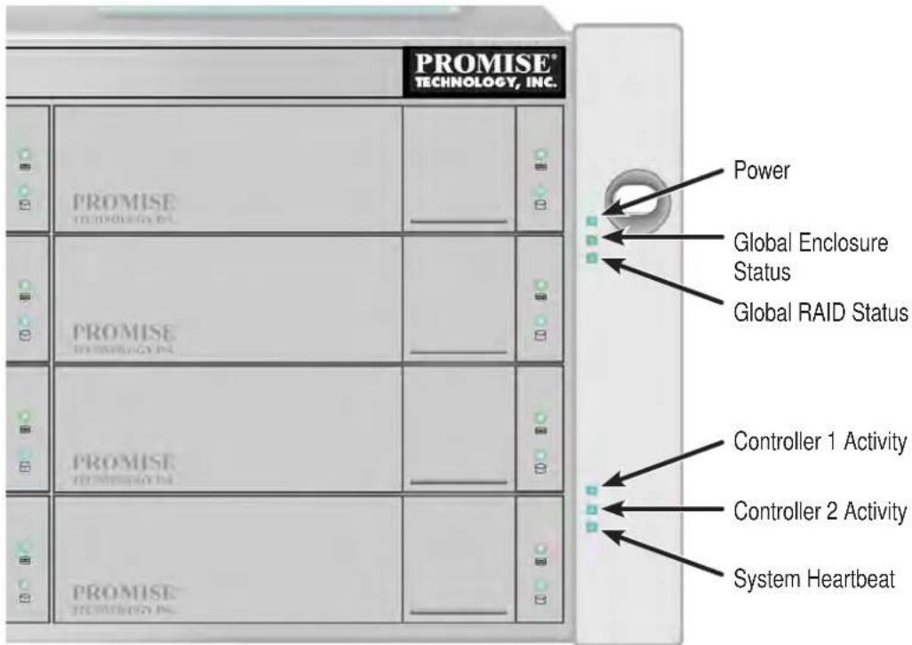
Right side LED behavior for the Vess R2600
| LED Description | |
| Power | Lights BLUE to indicate the system is powered on. |
| Global Enclosure Status | Lights GREEN when healthy; RED indicates multiple (three or more) Field Replacement Units (FRU) are in error; AMBER indicates one or two FRU are in error. |
| Global RAID Status | Lights GREEN when all logical drives are online; RED if any logical drive is offline, ORANGE for critical state of any logical drive. |
| Controller Activity | Flashes BLUE when I/O activity is detected on the controller, lights steady BLUE when no activity is detected, and remains dark when no controller is present. |
| System Heartbeat | Blinks BLUE slowly (once per second) to indicate the firmware and software are operating normally. |
REAR PANEL HARDWARE
The rear panel of the Vess R2000 Series enclosure provides access to the swappable power supplies, swappable cooling units, swappable controllers that include local and remote management physical connections, iSCSI (Ethernet) data ports, and Fibre Channel ports for Vess R2600fi controllers.
Vess R2600iD (pictured with optional PSU 4) back view

• Four 1Gb/s iSCSI ports per controller
• One JBOD Expansion port per controller
• Three PSU (optional fourth PSU available)
- Two Cooling Units (each Cooling Unit for Vess R2600 models include two fans and a BBU)
Vess R2600fiD back view

- Two 8Gb/s FC ports per controller
• Four 1Gb/s iSCSI ports per controller
• One JBOD Expansion port per controller
• Three PSU (optional fourth PSU available) - Two Cooling Units (each Cooling Unit for Vess R2600 models include two fans and a BBU)
Vess R2600fi controller LEDs

Vess R2600tiD back view
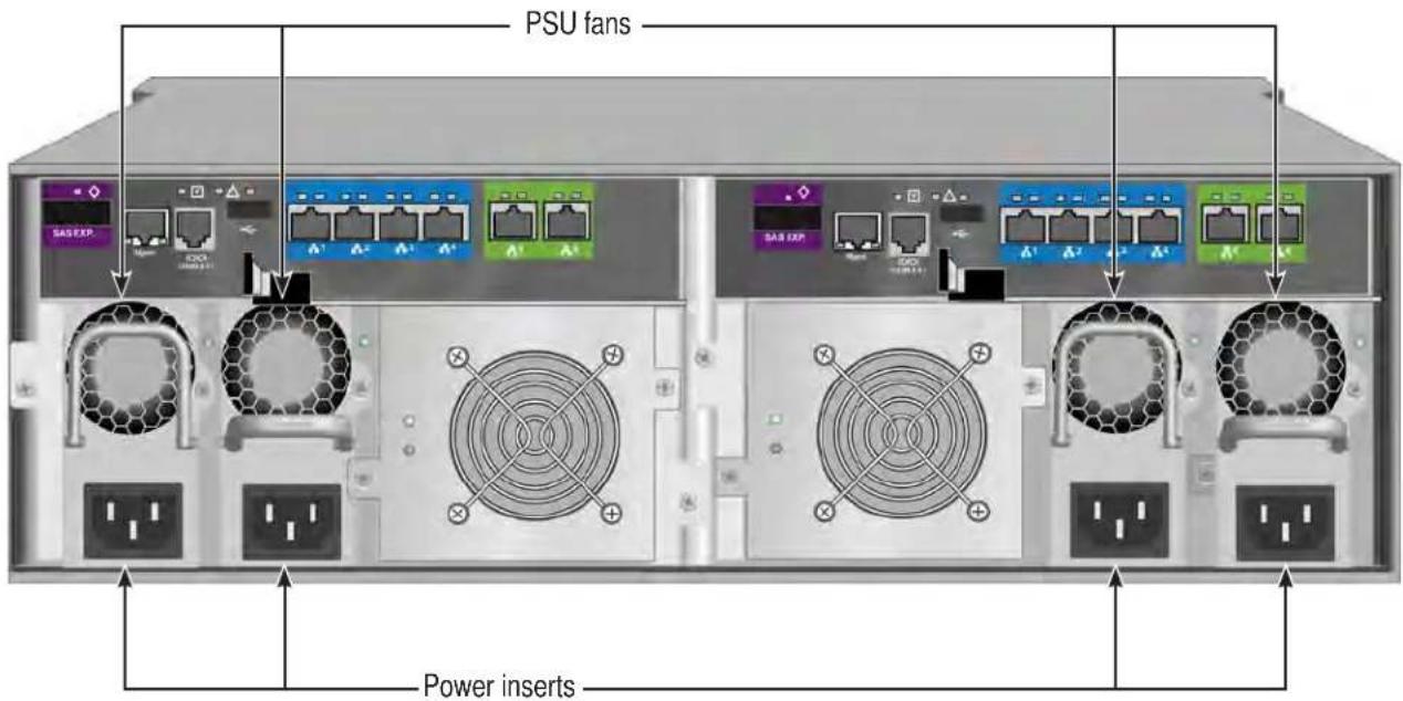
- Two 10Gb/s BASE-T iSCSI ports per controller
• Four 1Gb/s iSCSI ports per controller
• One JBOD Expansion port per controller
• Three PSU (optional fourth PSU available) - Two Cooling Units (each Cooling Unit for Vess R2600 models include two fans and a BBU)

Vess R2600xiD back view
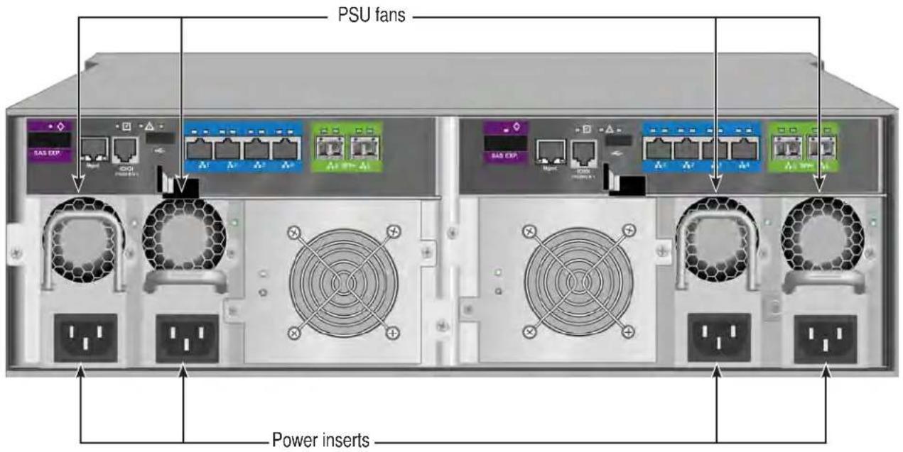
- Two 10Gb/s SFP+ iSCSI ports per controller
• Four 1Gb/s iSCSI ports per controller
• One JBOD Expansion port per controller
• Three PSU (optional fourth PSU available) - Two Cooling Units (each Cooling Unit for Vess R2600 models include two fans and a BBU)

Vess J2600sD back view

• Two SAS SFF-8088 ports per controller
• Three PSU (optional fourth PSU available)
- Two Cooling Units (each Cooling Unit for Vess J2600 models include two fans)
LEDs on Power Supply and Cooling Unit
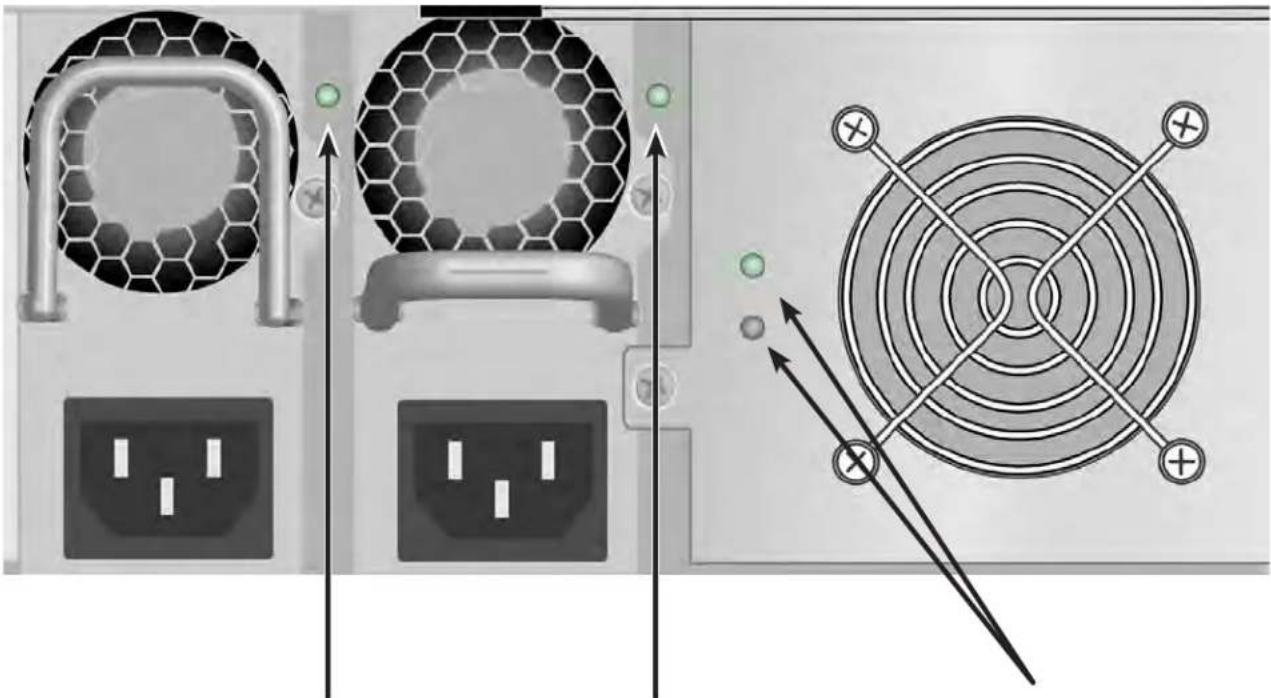
PSU 1 Status LED PSU 2 Status LED Cooling Unit 1 LEDs
- Battery Status (top)
• Cooling Unit Fan Status (bottom)
REAR PANEL LEDs
The LEDs on the rear panel include LEDs for I/O ports, controller status and dirty cache. The Vess R2600 enclosure also has a status LED on each of the hot-swappable PSUs and Cooling Units.
| LED | Description |
| Cooling Unit | A steady GREEN LED indicates normal fan function. A RED LED indicates fan failure, the fan must be replaced. |
| Battery Status | A GREEN indicator means there is more than 72 hours of capacity for backing up DDR, AMBER indicates there is less than 72 hours of capacity. RED indicates the battery is not functioning properly and should be replaced. |
| PSU Status | The power supply LEDs on the A2600 light GREEN to indicate normal operation. A RED LED indicates a problem or unit failure. |
| 1G iSCSI Link/Act and Speed | Two LEDs are located above each port. The left LED lights GREEN when connected, flashes GREEN when there is activity on the port and remains dark no connection has been established. The LED on the right of each port indicates connection speed, GREEN is 100 Mbps, AMBER is 1000 Mbps. |
| Fibre Channel (Vess R2600fi) | A single LED above each port. Indicates port speed and status with blink and color pattern. See “Fibre Channel port LED behavior (Vess R2600fi controller)” on page 22 for complete description. |
| 10G BASE-T iSCSI (Vess R2600ti) Link/Act and Speed | Two LEDs are located above each port. The left LED lights GREEN when connected, flashes GREEN when there is activity on the port and remains dark no connection has been established. The LED on the right of each port indicates connection speed, AMBER is 1000 Mbps, GREEN is 10000 Mbps. |
| 10G SFP+ iSCSI (Vess R2600xi) Link/Act and Speed | Two LEDs are located above each port. The left LED lights GREEN when connected, flashes GREEN when there is activity on the port and remains dark no connection has been established. The LED on the right of each port indicates connection speed, GREEN is 10000 Mbps, AMBER is 1000 Mbps, |
| SAS Expansion | Lights green when connected, flashes green when active. |
| Controller Status | This displays the current operational status of the controller. A steady (unblinking) green light indicates the controller is operational. |
| Dirty Cache | Blinks amber if cache is dirty, meaning that the controller memory cache contains data, otherwise this is dark. |
| USB | A steady green light indicates a valid USB connection, this is dark when not connected (no device attached). |

Note
Note that the 10G port speed LED indicator is different than the 1G ports, a GREEN speed LED is the fastest speed on the 10G port, in contrast to the 1G iSCSI I/O ports where GREEN is the slowest speed. AMBER indicates 1000 Mbps on both port types.
FIBRE CHANNEL PORT LED BEHAVIOR (VESS R2600FI CONTROLLER)
| LED Description | |||
| FC ports(one LED above each port) | Green Amber Status | ||
| dark dark | Wake-up failure (dead board) | ||
| off on POST failure (dead board) | |||
| off blinking slowly Wake-up failure monitor | |||
| off blinking rapidly Failure to POST | |||
| off flashing POST in progress | |||
| on off Failure while functioning | |||
| on on Failure while functioning | |||
| on 2 rapid blinks Normal, link up, 2 Gb/s | |||
| on 3 rapid blinks Normal, link up, 4 Gb/s | |||
| on 4 rapid blinks Normal, link up, 8 Gb/s | |||
| blinking slowly off Normal, link down | |||
| blinking slowly blinking slowly Offline for download | |||
| blinking slowly blinking rapidly Restricted offline mode(waiting for restart) | |||
| blinking slowly flashing Restricted offline mode, test active | |||
SYSTEM MANAGEMENT
MANAGEMENT INTERFACES

Note
There are two options to provide the physical connection for system management for the Vess R2600 models, an RJ-11 serial port or an RJ-45 Ethernet network port An RJ-11-to-DB9 adapter is shipped with each Vess R2000 Series model.
- Browser-based management with WebPAM PROe over Ethernet
• Command Line Interface (CLI) over Serial Port, Ethernet via Telnet, or SSH
• Command Line Utility (CLU) over Serial Port, Ethernet via Telnet, or SSH
• Third Party Management Support via SNMP
ADVANCED STORAGE FEATURES
- Perfect Rebuild
• Advanced Battery Flash Backup
• Online LUN Clone (SR2)
• Advanced Cache Mirroring over PCIe Gen2
• Simple, drag-and-drop LUN Masking and Mapping
• Asymmetric LUN Unit Access (ALUA)
• Volume Copy
• PerfectFlash - Non-Disruptive Software Updatez
• I/O performance & power monitoring tools
• Guaranteed Latency Technology (an advanced OEM feature) - USB Service Log
BACKGROUND ACTIVITIES
• Media Patrol
• Background Synchronization
• Foreground Initialization
- Rebuild
- Redundancy Check
- Disk SMART Polling
• Online Capacity Expansion (OCE)
• RAID Level Migration (RLM)
- UPS Monitoring
- Feature rich task scheduler for background activities
PERFECTRAID FEATURES
• Predictive Data Migration (PDM)
• Intelligent Bad Sector Remapping
• SMART Error Handling
- NVRAM Error Logging
- Disk Slot Power Control
- Read/Write Check Table
- Write Hole Table
SUPPORTED BROWSERS
Browsers run on the host PC or server, from which you monitor and manage the Vess R2600 subsystem using WebPAM PROe. The browsers listed here meet the minimum version requirements for browser compatibility:
- Mozilla Firefox 14.0.1
• Google Chrome 20.0.1132.57 m
• Internet Explorer 7 (Version: 7.0.5730.13)
• Internet Explorer 8 (Version: 8.0.6001.18702)
• Internet Explorer 9 (Version: )
• Safari 5.1.7 for Windows - Safari 5.1.7 for MAC
• Mozilla Firefox for Linux 3.6.13
For the latest list of supported browsers, go to PROMISE support:
http://www.promise.com/support/
Operating systems run on the Host PC, from which you monitor and manage the Vess R2000 subsystem.
| Core Platform | Type Notes | |
| Microsoft | ||
| Windows Server 2003 Enterprise Edition R2 with SP2 x86 / x64 | ||
| Windows Server 2008 Datacenter Edition with SP2 x86/ x64 | ||
| Windows Server 2008 R2 SP1 Datacenter Edition x64 | ||
| RedHat | ||
| Enterprise Linux 5.7 x86 / x64 | ||
| Enterprise Linux 6.3 x86 / x64 | ||
| SuSE | ||
| Linux Enterprise Server 10 + SP4 x86 / x64 SUSE LINUX Enterprise | Server 10 + SP4-32bit can't support dual controller boot from SAN | |
| Linux Enterprise Server 11 + SP2 x86 / x64 | SUSE LINUX Enterprise Server 11 + SP2-32bit can't support dual controller boot from SAN | |
NAS SHARED DISK FILE SYSTEM
Release 2 of the Vess R2000 Series incorporates principles of unified storage into its core operation in order to simplify and streamline administration of storage resources and provide greater flexibility to administrators. The Vess R2000 supports file-based NAS and block-based SAN to allow users and applications to access data consolidated on a single device. The tasks of planning, setup and configuration of a NAS environment differ from the same tasks for a SAN. It is recommended that administrators who intend to use the Vess 2000 NAS function read the chapter dedicated to NAS function, “NAS Function and Management” on page 250 before setting up NAS and SAN resources.
WARRANTY AND SUPPORT
WARRANTY
• Three year complete system limited warranty
- Battery Backup Unit has a one year limited warranty
• Optional 2-year extended warranty
- Optional onsite parts replacement program
Promise Technology, Inc. ("Promise") warrants that for three (3) years from the time of the delivery of the product to the original end user except for one (1) year warranty on the battery backup unit:
a) the product will conform to Promise's specifications;
b) the product will be free from defects in material and workmanship under normal use and service.
This warranty:
a) applies only to products which are new and in cartons on the date of purchase;
b) is not transferable;
c) is valid only when accompanied by a copy of the original purchase invoice;
d) is not valid on spare parts.
This warranty shall not apply to defects resulting from:
a) improper or inadequate maintenance, or unauthorized modification(s), performed by the end user;
b) operation outside the environmental specifications for the product;
c) accident, misuse, negligence, misapplication, abuse, natural or personal disaster, or maintenance by anyone other than a Promise or a Promise authorized service center.
HARDWARE INSTALLATION
This chapter presents the basics on unpacking the Vess R2000 Series enclosure and mounting it in an equipment rack, making the connections for data and management paths and connecting the power. It also describes how to power on the system and what to look for while it is powering up.
The main sections in Hardware Setup include the following:
• "Unpacking" on page 30
- "Mounting the Vess enclosure in a rack" on page 31
• "Installing Physical Drives" on page 35
- "Making Management and Data Connections" on page 39
• "Connecting the Power" on page 59
Depending on the details of your order, the Vess R2000 enclosure might be shipped with hard drives installed, or it might require that you install hard drives. The section “Installing Physical Drives” on page 35 provides instruction for installing hard disks.
UNPACKING
PACKING LIST
The Vess R2000 Series box contains the following items:
- Vess R2000 Unit
• One Quick Start Guide printed
• A DVD containing the Product Manual
• Two 1.5m (4.9 ft) Power cords
- Adjustable rack mounting rail assembly
• DB9 to RJ-11 adapter for serial connection

Warning
The electronic components within the Vess enclosure are sensitive to damage from Electro-Static Discharge (ESD). Observe appropriate precautions at all times when handling the Vess or its subassemblies.
MOUNTING THE VESS ENCLOSURE IN A RACK
This section provides instructions for installing the Vess R2000 enclosure into a rack

Caution
To lighten the enclosure, remove the power supplies, and remove all hard drive carriers. Replace the power supplies and drive carriers after the unit is mounted in your rack.
Cautions

- Do not populate any unit with hard drives until it has been securely installed in the rack.
- At least two persons are required to safely lift, place, and attach the unit into a rack system.
- Do not lift or move the unit by the handles, power supplies or the controller units. Hold the system itself.
- Do not install the unit into a rack without rails to support the system.
- Only a qualified technician who is familiar with the installation procedure should mount and install the unit.
- Mount the rails to the rack using the appropriate screws and flange nuts, fully tightened, at each end of the rail.
- Do not load the rails unless they are installed with screws as instructed.
- The rails available for the PROMISE Vess unit are designed to safely support that PROMISE Vess unit when properly installed. Additional loading on the rails is at the customer's risk.
- PROMISE Technology, Inc. cannot guarantee that the mounting rails will support your PROMISE Vess unit unless you install them as instructed.
To install the Vess into a rack with the supplied mounting rails:
- Check the fit of the mounting rails in your rack system.
-
Adjust the length of the mounting rails as needed.
-
The rear rail slides inside the front rail. The rails are composed of two sliding sections and do not require adjusting screws.
• The front-left and front-right mounting rail ends are labeled. - Be sure the front rail support is on the bottom facing inward.
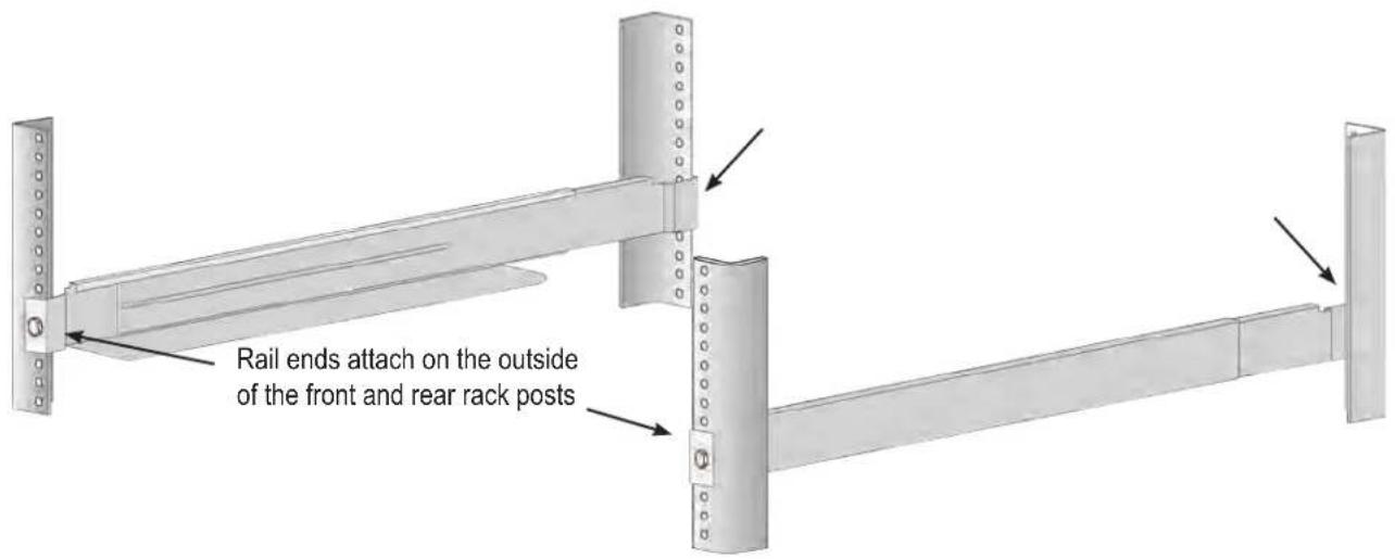
Installing the rails onto the rack

Guide pins on rails align with holes in the rack post
- All rail ends, front and rear, attach at the outside of the rack posts.
- The guide pins at the rail ends align with the holes in the rack posts.
- Use the attaching screws and flange nuts from your rack system. Tighten the screws and nuts according to instructions for your rack system.
Rail ends attach to the outside of each post
-
Place the Vess onto the rails.
-
At least two persons are required to safely lift the system.
- Lift the Vess itself. Do not lift the system by its brackets.
Placing the Vess enclosure onto the rack rails

- Secure the enclosure to the rack.
• Use the included screws and flange nuts to lock the unit in to place in the rack.
- Use the attaching screws and flange nuts that came with the Vess enclosure.
Secure to rack

INSTALLING PHYSICAL DRIVES
The Vess R2000 Series subsystems support:
• SAS and SATA hard disks
• 3.5-inch hard disk drives
For a list of supported physical drives, download the latest compatibility list from the PROMISE support website.
NUMBER OF DRIVES REQUIRED
The table below shows the number of drives required for each RAID level
| Level | Number of Drives | Level | Number of Drives |
| RAID 0 | 1 or more | RAID 6 | |
| RAID 1 | 2 only | RAID 10 | |
| RAID 1E | 2 or more | RAID 30 | |
| RAID 3 | 3 to 32 | RAID 50 | |
| RAID 5 | 3 to 32 |
*Must be an even number of drives.

Caution
The Vess R2000 supports disk drive hot-swapping. To avoid hand contact with an electrical hazard, do not remove more than one drive carrier a time.
DRIVE SLOT NUMBERING
You can install any suitable disk drive into any slot in the enclosure. The diagrams below show how drive slots are numbered. Slot numbering is reflected in the WebPAM PROe and CLU user interfaces.
Drive slot numbering on Vess R2600

Install all of the drive carriers into the Vess R2000 enclosure to ensure proper airflow, even if you do not populate all the carriers with physical drives.
INSTALLING YOUR DRIVES
The drive carrier accommodates 2.5-inch and 3.5-inch drives, with or without a SAS-to-SATA adapter.

Cautions
Swing open the drive carrier handle before you insert the drive carrier into the enclosure.
To avoid hand contact with an electrical hazard, remove only one drive carrier a time.

Important
SATA drives require a SAS-to-SATA adapter, available from PROMISE Technology at http://www.promise.com
SAS drives do not require adapters.
- Press the drive carrier release button. The handle springs open.
- Grasp the handle and gently pull the empty drive carrier out of the enclosure.
Drive carrier front view

Disk carrier release button
- If you are installing SATA drives, attach a SAS-to-SATA adapter onto the power and data connectors of each drive.
-
Carefully lay the drive into the carrier with the power and data connectors facing away from the carrier handle.
-
Position the drive in the carrier so the mounting holes line up.
• 2.5-inch drive mounting screws go through the bottom of the carrier.
- SAS-to-SATA adapter mounting screws go through the bottom of the carrier.
• 3.5-inch drive mounting screws go through the sides of the carrier.
Drive carrier bottom view

natural_image
Technical line drawing of a four-panel electronic device casing with mounting holes and internal compartments (no text or symbols)Drive carrier side view

-
Insert the screws through the proper holes in the carrier and into the drive or adapter.
-
Use the screws supplied with the shipment or the SAS-to-SATA adapter.
• Install four screws per drive.
• Install two screws per adapter. -
Snug each screw. Be careful not to over tighten.
-
With the drive carrier handle in open position, gently slide the drive carrier into the enclosure.

Important
Press the release button to push the drive carrier into position.
Proper drive installation ensures adequate grounding and minimizes vibration. Always attach the drive to the carrier with four screws.
MAKING MANAGEMENT AND DATA CONNECTIONS
Examples of Vess R2000 Series cabling for data and management in this section include:
- "Fibre Channel SAN" on page 40
- "Fibre Channel DAS" on page 43
- “Fibre Channel with JBOD Expansion” on page 45
- “Fibre Channel SAN – No Single Point of Failure” on page 47
- "iSCSI Storage Area Network (SAN)" on page 51
- "iSCSI Direct Attached Storage (DAS)" on page 54
- "iSCSI with JBOD Expansion" on page 56
FIBRE CHANNEL SAN

Important
For a list of supported HBAs, Switches, and SFP transceivers, download the latest compatibility list from PROMISE support: http://www.promise.com/support/.
FC data and management ports on the Vess R2600fi RAID controller
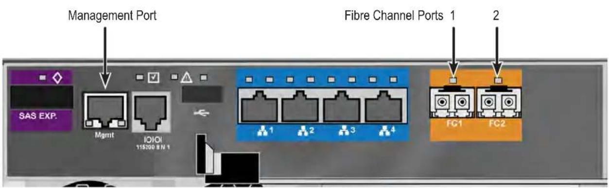
A Fibre Channel storage area network (SAN) requires:
• An FC HBA card in each host PC or server
- An SFP transceiver for each connected FC port on the subsystem
- An FC switch
- A network switch
FC SAN DATA PATH
To establish the data path:
- Connect FC cables between at least one FC data port on each RAID controller and the FC switch. See "FC SAN data and management connections" on page 42.
- Connect FC cables between the FC switch and the FC HBA cards in both host PCs or servers. If you have multiple Vess R2600 subsystems, repeat steps 1 and 2 as required.
MANAGEMENT PATH
To establish the management path:
- Connect Ethernet cables between the Management ports on the RAID controllers and the network switch. See "FC SAN data and management connections" on page 42
- Connect Ethernet cables between the network ports on both host PCs or servers and the network switch. If you have multiple Vess R2600 subsystems, repeat steps 1 and 2 as required.
The Vess R2600fiD subsystem is shown with SFP transceivers installed.
FC SAN data and management connections
FIBRE CHANNEL DAS

Important
For a list of supported HBAs, switches, and SFP transceivers, download the latest compatibility list from PROMISE support: http://www.promise.com/support/.
Fibre Channel direct attached storage (DAS) requires:
• An FC HBA card in the host PC or server
- An SFP transceiver for each connected FC port on the subsystem
- A network switch
FC DAS DATA PATH
To establish the data path:
- Connect an FC cable between a data port on a RAID controller and the FC HBA card in your host PC or server.
See "FC DAS data and management connections" on page 44 - For dual controller Vess subsystem, connect an FC cable between a data port on the remaining RAID controller and the FC HBA card in your host PC or server.
MANAGEMENT PATH
To establish the management path:
- Connect Ethernet cables between the Management ports of the RAID controllers and the network switch. See "FC DAS data and management connections" on page 44.
- Connect an Ethernet cable between the network port on the host PC or server and the network switch.
The Vess R2600fiD subsystem is shown with SFP transceivers installed.
FC DAS data and management connections

FIBRE CHANNEL WITH JBOD EXPANSION
JBOD expansion requires at least one SFF-8088 4X to SFF-8088 4X external SAS cable for each JBOD unit.
To add JBOD units:
-
Connect the SAS expansion port on the left controller of the RAID subsystem to the SAS data IN port on the left I/O module of the first JBOD unit.
See "Vess R2600fiD with FC JBOD expansion connections" on page 46 -
Connect the SAS expansion port on the right controller of the RAID subsystem to the SAS data IN port on the right I/O module of the first JBOD unit.
-
Connect the SAS data OUT port on left I/O module of the first JBOD unit to the SAS data IN port on the left I/O module of the second JBOD unit.
-
Connect the SAS data OUT port on right I/O module of the first JBOD unit to the SAS data IN port on the right I/O module of the second JBOD unit.
-
Connect the remaining JBOD units in the same manner.
-
Keep your data paths organized to ensure redundancy.
• JBOD expansion supports up to four JBOD units.
The Vess R2600fiD subsystem is shown with SFP transceivers installed.
Vess R2600fiD with FC JBOD expansion connections

flowchart
graph TD
    A["Server Rack"] --> B["Switch 1"]
    A --> C["Switch 2"]
    A --> D["Switch 3"]
    A --> E["Switch 4"]
    A --> F["Switch 5"]
    A --> G["Switch 6"]
    A --> H["Switch 7"]
    A --> I["Switch 8"]
    A --> J["Switch 9"]
    A --> K["Switch 10"]
    A --> L["Switch 11"]
    A --> M["Switch 12"]
    A --> N["Switch 13"]
    A --> O["Switch 14"]
    A --> P["Switch 15"]
    A --> Q["Switch 16"]
    A --> R["Switch 17"]
    A --> S["Switch 18"]
    A --> T["Switch 19"]
    A --> U["Switch 20"]
    A --> V["Switch 21"]
    A --> W["Switch 22"]
    A --> X["Switch 23"]
    A --> Y["Switch 24"]
    A --> Z["Switch 25"]
    A --> AA["Switch 26"]
    A --> AB["Switch 27"]
    A --> AC["Switch 28"]
    A --> AD["Switch 29"]
    A --> AE["Switch 30"]
    A --> AF["Switch 31"]
    A --> AG["Switch 32"]
    A --> AH["Switch 33"]
    A --> AI["Switch 34"]
    A --> AJ["Switch 35"]
    A --> AK["Switch 36"]
    A --> AL["Switch 37"]
    A --> AM["Switch 38"]
    A --> AN["Switch 39"]
    A --> AO["Switch 40"]
    A --> AP["Switch 41"]
    A --> AQ["Switch 42"]
    A --> AR["Switch 43"]
    A --> AS["Switch 44"]
    A --> AT["Switch 45"]
    A --> AU["Switch 46"]
    A --> AV["Switch 47"]
    A --> AW["Switch 48"]
    A --> AX["Switch 49"]
    A --> AY["Switch 50"]
FIBRE CHANNEL SAN – No SINGLE POINT OF FAILURE
An FC SAN with no single point of failure (NSPF) requires:
- An FC HBA card in each host PC or server
- An SFP transceiver for each connected FC port on the subsystem
- Two FC switches
- A network switch
FC SAN NSPF DATA PATH
To establish the data path:
- Connect an FC cable between an FC data port on the left RAID controller and one of the FC switches.
See "FC SAN NSPF data connections" on page 48 - Connect an FC cable between an FC data port on the left RAID controller and the other FC switch.
- Connect an FC cable between an FC data port on the right RAID controller and one of the FC switches.
- Connect an FC cable between an FC data port on the right RAID controller and the other FC switch.
- Connect FC cables between one of the FC switches and the FC HBA cards in both of the host PCs or servers.
- Connect FC cables between the other FC switch and the FC HBA cards in both of the host PCs or servers. If you have multiple Vess R2000 subsystems, repeat steps 1 through 6 as required.

Important
For a list of supported HBAs, switches, and SFP transceivers, download the latest compatibility list from PROMISE support:
http://www.promise.com/support/.
The Vess R2600fiD subsystem is shown with SFP transceivers installed.
FC SAN NSPF data connections

FC SAN NSPF MANAGEMENT PATH
To establish the management path:
- Connect an Ethernet cable between the Management port on each RAID controller and the network switch.
See "FC SAN NSPF management connections" on page 50 - Connect an Ethernet cable between the network port on each host PC or server and the network switch. If you have multiple Vess R2000 subsystems, repeat steps 1 and 2 as required.
JBOD EXPANSION
JBOD connections are the same for all FC SAN and DAS configurations.
The Vess R2000 subsystem is shown with SFP transceivers installed.
FC SAN NSPF management connections

ISCSI STORAGE AREA NETWORK (SAN)

Important
For a list of supported HBA NICs and switches, download the latest compatibility list from PROMISE support: http://www.promise.com/support/.
This arrangement requires:
- An iSCSI HBA network interface card (NIC) in the host PC or server
- A network switch

Note
Only one iSCSI data cable is required between each RAID controller and the network switch. However, you can attach multiple cables to create redundant data paths or trunking.
ISCSI SAN DATA PATH
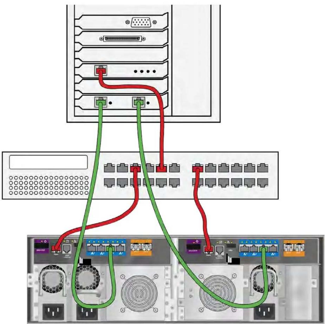
Each Vess R2600 controller has four (4) RJ45 iSCSI data port connectors. See “iSCSI SAN data and management connections” on page 53.
To establish the data path:
- Connect Ethernet cables between the iSCSI NIC in both host PCs or servers and the network switch.
See "iSCSI SAN data and management connections" on page 53
-
Connect an Ethernet cable between at least one iSCSI data port on the left RAID controller and the network switch.
-
Connect an Ethernet cable between at least one iSCSI data port on the right RAID controller and the network switch.
If you have multiple Vess R2600 subsystems, host PCs or servers, repeat steps 1 through 3 as required.
iSCSI data and management ports on the RAID controller

MANAGEMENT PATH
Each Vess R2600 controller has one (1) Ethernet RJ45 management port connector.
To establish the management path:
- Connect Ethernet cables between the network connector on both host PCs or servers and the standard network switch.
See "iSCSI SAN data and management connections" on page 53
- Connect Ethernet cables between the Management port on both RAID controllers to the standard network switch.
If you have multiple Vess R2600 subsystems, repeat steps 1 and 2.
iSCSI SAN data and management connections

flowchart
graph TD
    A["Server Rack"] --> B["Red Wire"]
    A --> C["Green Wire"]
    A --> D["Blue Wire"]
    B --> E["Port 1"]
    C --> F["Port 2"]
    D --> G["Port 3"]
    E --> H["Terminal 1"]
    F --> I["Terminal 2"]
    G --> J["Terminal 3"]
    H --> K["Terminal 4"]
    I --> L["Terminal 5"]
    J --> M["Terminal 6"]
    K --> N["Terminal 7"]
    L --> O["Terminal 8"]
    M --> P["Terminal 9"]
    N --> Q["Terminal 10"]
    O --> R["Terminal 11"]
    P --> S["Terminal 12"]
    Q --> T["Terminal 13"]
    R --> U["Terminal 14"]
    S --> V["Terminal 15"]
ISCSI DIRECT ATTACHED STORAGE (DAS)

Important
For a list of supported HBAs and switches, download the latest compatibility list from PROMISE support: http://www.promise.com/support/.
This arrangement requires:
- An iSCSI HBA network interface card (NIC) in the host PC or server
• A standard network switch
DATA PATH
Each Vess R2600ti and Vess R2600i controller has four (4) RJ45 iSCSI data port connectors. See
To establish the data path:
- Connect an Ethernet cable between the iSCSI NIC in the host PC or server and an iSCSI data port on one of the RAID controller.
- Connect an Ethernet cable between the iSCSI NIC in the host PC or server and an iSCSI data port on the other RAID controller.
MANAGEMENT PATH
Each Vess R2600ti, Vess R2600fi, and Vess R2600i controller has one (1) Ethernet RJ-45 management port connector.
To establish the management path:
- Connect an Ethernet cable between the network connector on the host PC or server and the standard network switch.
See "iSCSI DAS data and management connections" on page 55 - Connect Ethernet cables between the standard network switch and the Management ports on both RAID controllers.
iSCSI DAS data and management connections
flowchart
graph TD
    A["Server Rack"] --> B["Port 1"]
    A --> C["Port 2"]
    A --> D["Port 3"]
    A --> E["Port 4"]
    A --> F["Port 5"]
    A --> G["Port 6"]
    A --> H["Port 7"]
    A --> I["Port 8"]
    A --> J["Port 9"]
    A --> K["Port 10"]
    A --> L["Port 11"]
    A --> M["Port 12"]
    A --> N["Port 13"]
    A --> O["Port 14"]
    A --> P["Port 15"]
    A --> Q["Port 16"]
    A --> R["Port 17"]
    A --> S["Port 18"]
    A --> T["Port 19"]
    A --> U["Port 20"]
    A --> V["Port 21"]
    A --> W["Port 22"]
    A --> X["Port 23"]
    A --> Y["Port 24"]
    A --> Z["Port 25"]
ISCSI WITH JBOD EXPANSION
JBOD expansion requires at least one SFF-8088 4X to SFF-8088 4X external SAS cable for each JBOD unit. To add JBOD units:
- Connect the SAS expansion port on the left controller of the RAID subsystem to the SAS data IN port on the left I/O module of the first JBOD unit.
See "Vess R2600i with SAS JBOD expansion" on page 57
- Connect the SAS expansion port on the right controller of the RAID subsystem to the SAS data IN port on the right I/O module of the first JBOD unit.
- Connect the SAS data OUT port on left I/O module of the first JBOD unit to the SAS data IN port on the left I/O module of the second JBOD unit.
- Connect the SAS data OUT port on right I/O module of the first JBOD unit to the SAS data IN port on the right I/O module of the second JBOD unit.
- Connect the remaining JBOD units in the same manner.
- Keep your data paths organized to ensure redundancy.
• JBOD expansion supports up to four JBOD units.
Vess R2600i with SAS JBOD expansion

flowchart
graph TD
    A["Server Rack 1"] -->|Ethernet Cable| B["Server Rack 2"]
    B --> C["Server Rack 3"]
    C --> D["Server Rack 4"]
    D --> E["Server Rack 5"]
    E --> F["Server Rack 6"]
    F --> G["Server Rack 7"]
    G --> H["Server Rack 8"]
    H --> I["Server Rack 9"]
    I --> J["Server Rack 10"]
    J --> K["Server Rack 11"]
    K --> L["Server Rack 12"]
    L --> M["Server Rack 13"]
    M --> N["Server Rack 14"]
    N --> O["Server Rack 15"]
    O --> P["Server Rack 16"]
    P --> Q["Server Rack 17"]
    Q --> R["Server Rack 18"]
    R --> S["Server Rack 19"]
    S --> T["Server Rack 20"]
    T --> U["Server Rack 21"]
    U --> V["Server Rack 22"]
    V --> W["Server Rack 23"]
    W --> X["Server Rack 24"]
    X --> Y["Server Rack 25"]
    Y --> Z["Server Rack 26"]
MAKING SERIAL CABLE CONNECTIONS
Serial communication enables the terminal emulation application on your host PC or server to access the Vess Command Line Interface (CLI) to set up a network connection. The Vess R2000 Series package includes one RJ11-to-DB9 serial data cable for each controller.
To set up a serial cable connection:
- Attach the RJ-11 end of the serial data cable to the RJ-11 serial connector on one of the RAID controllers.
- Attach the DB9 end of the serial data cable to a serial port on the host PC or server.
Serial port connection

Use the RJ-11 serial port on the controller module to establish the serial communication link. The Vess R2600 is shipped with an RJ-11 to DB9 adapter to be used for this purpose.

CONNECTING THE POWER
To power on the Vess R2600 and any connected Vess J2600 system, follow these steps:
- Connect the power insert for all power supplies on all units.
- Plug in the power cables on all power cords to a suitable grounded power source.
- To turn on the power to the Vess J2600 or Vess R2600 units, press the power button on the front of the left handle of the Vess R2600 devices. See "Front left view of Vess R2600" below for an illustration of the power button. The Vess R2600 features an automatic JBOD detect and power on sequence mechanism so that all connected Vess J2600 expansion units are powered on in the correct sequence. This feature will first power on the Vess J2600s and then the Vess R2600 units in the correct sequence automatically.
After the powering on the Vess R2600 and Vess J2600 units, check the LEDs to monitor the devices.
Front left view of Vess R2600

LED BEHAVIOR
When the power is switched on, the LEDs on the right handle light up. See
When boot-up is finished and the Vess R2600 is functioning normally:
- When boot-up is finished and the Vess R2600 subsystem is functioning normally:
• Power, Global Enclosure Status, and Global RAID Status LEDs display green continuously. - Controller Activity LED flashes green when there is controller activity.
- System Heartbeat LED blinks blue (once a second), and repeats the pattern.
See the sections that follow for more details on device LED indicator behavior.
Front right view of Vess R2600
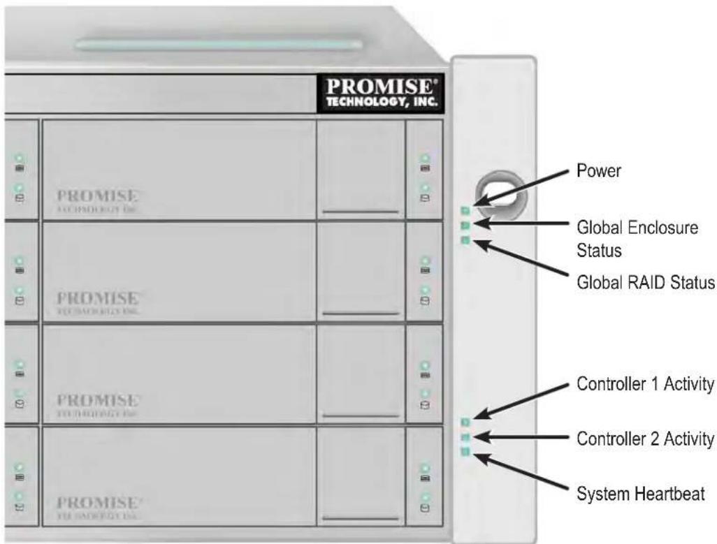
FRONT LED BEHAVIOR AFTER BOOT UP
| LED State | Power | Global Enclosure Status | Global RAID Status | Controller Activity | System Heartbeat |
| Dark | No power — — | No controller present | — | ||
| Steady Green | — | All devices normal | All logical drives online | — | — |
| Steady Blue | Normal — — | No activity — | |||
| Blinking Blue | — — — Normal** | ||||
| Flashing Blue | — — — | I/O Activity — | |||
| Flashing Green | — | Locating device | — — — | ||
| Amber | — | One or two FRU in error* | Logical drive(s) critical | — | — |
| Red | — | Three or more FRU in error* | Logical drive(s) offline | — | — |
* Check the LEDs on the back of the enclosure.
** Blinks blue once per second for five seconds, goes dark for ten seconds, then blinks green once per second for five seconds again.
Disk Carrier LEDs - front of every carrier

The Vess R2600 spins up the disk drives sequentially to equalize power draw during start-up. After a few moments:
• The Power/Activity LED displays blue when a physical drive is present.
- The Drive Status LED displays green when the physical drive is configured as a member of a disk array or as a spare. When the physical drive is not configured, the LED is dark.
In the table below:
• Steady means the LED is on.
- Blinking means a regular on/off pattern.
- Flashing means intermittent and irregular on/off pattern.
DRIVE STATUS LED BEHAVIOR AFTER BOOT UP
| State | Power/Activity Drive Status | |
| Dark | No drive in carrier Drive is not configured | |
| Steady Blue | Drive in carrier – | |
| Flashing Blue | Activity on drive – | |
| Steady Green – | Drive is configured | |
| Blinking Green – | Locator feature | |
| Amber – | Drive is rebuilding | |
| Red – | Drive error of failure | |
* Configured means the physical drive either belongs to an array or it is assigned as a spare drive.
REAR PANEL PSU & COOLING UNIT LEDs
The LEDs on the rear panel include LEDs on each cooling fan and each power supply. These LEDs will light green to indicate normal operation. A red LED indicates a problem or unit failure.
LEDs on Power Supply and Cooling Unit

PSU 1 Status LED PSU 2 Status LED Cooling Unit 1 LEDs
- BBU (top)
• Cooling Unit Fan Status (bottom)
CONTROLLER LEDs
When boot-up is finished and the Vess R2600 subsystem is functioning normally:
• Controller status LEDs display green continuously.
- Ethernet LEDs display green or flash depending on your network connection.
• The FC, iSCSI, SAS, and Expansion LEDs display green or flash during port activity.
FC controller LEDs
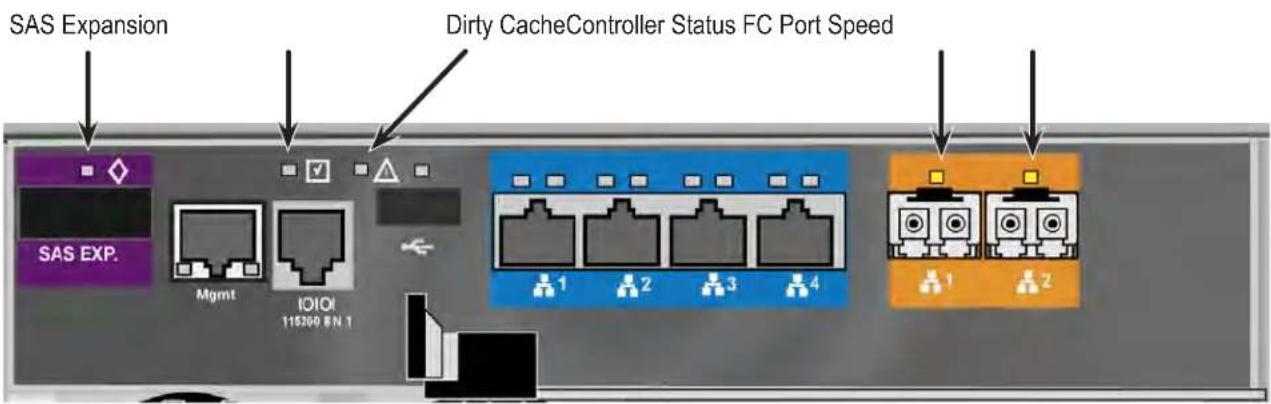

Note
The controller LEDs on the FC and iSCSI controllers are the same except those that indicate network function.
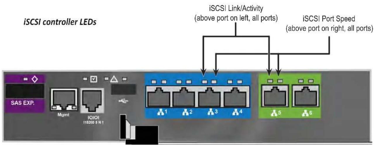
CONTROLLER LED BEHAVIOR
When boot-up is finished and the Vess R2000 subsystem is functioning normally, the Controller status LED displays green continuously; the Management port LEDs display green or flash depending on your network connection; the FC, iSCSI, and SAS Expansion LEDs display green or flash during port activity.
| LED Description | |
| SAS Expansion | Lights green when connected, flashes green when active. |
| Controller Status | This displays the current operational status of the controller. A steady (unblinking) green light indicates the controller is operational. |
| Dirty Cache | Blinks amber if cache is dirty, meaning that the controller memory cache contains data, otherwise this is dark. |
| USB | A steady green light indicates a valid USB connection, this is dark when not connected (no device attached). |
| 1G iSCSI(2 above each port) | Left LED lights green when connected, flashes green when active, dark if not connected. Right LED indicates connection speed, green is 100 Mbps, amber is 1000 Mbps. |
| 10G BASE-T iSCSI(Vess R2600ti)Link/Act and Speed | Two LEDs are located above each port. The left LED lights GREEN when connected, flashes GREEN when there is activity on the port and remains dark no connection has been established. The LED on the right of each port indicates connection speed, GREEN is 10000 Mbps, AMBER is 1000 Mbps, |
| 10G SFP+ iSCSI(Vess R2600xi)Link/Act and Speed | Two LEDs are located above each port. The left LED lights GREEN when connected, flashes GREEN when there is activity on the port and remains dark no connection has been established. The LED on the right of each port indicates connection speed, GREEN is 10000 Mbps, AMBER is 1000 Mbps, |
| FC ports*** | A single LED above each port. Indicates port speed and status with blink and color pattern. See “Fibre Channel port LED behavior (Vess R2600fi controller)” on page 22 for complete description. |
* Vess R2600ti controller has two 10G iSCSI ports.
** Vess 2600xi controller has two 10G SFP+ iSCSI ports for Fibre Optic cabling
*** Vess R2600fi controller has two Fibre Channel ports.

Note
Note that the 10G port speed LED indicator is different than the 1G ports, a GREEN speed LED is the fastest speed on the 10G port, in contrast to the 1G iSCSI I/O ports where GREEN is the slowest speed. AMBER indicates 1000 Mbps on both port types.
SYSTEM SETUP
Now that the Vess R2000 subsystem is installed and connected, it is time to continue with setting up the storage arrays and perform other administration functions. You have a choice of user interfaces for management and administration of the Vess R2000. The administrator can choose to use WebPAM PROe, a web-based graphical user interface (GUI), or use the command line interfaces, or CLI. These are both described in detail in separate chapters.
This chapter covers the following topics:
• "Setting-up the Serial Connection" on page 67
- "About IP Addresses" on page 68
- "Setting-up with the CLI" on page 72
- "Setting up with WebPAM PROe" on page 82
SETTING-UP THE SERIAL CONNECTION
The initial connection accesses the serial port using the serial cable connection you made using the RJ-11 to DB9. Use your PC's terminal emulation program, such as Microsoft HyperTerminal, to access the Command Line Interface (CLI).
To make the initial serial connection:
-
Change your terminal emulation application settings to match the following specifications:
-
Bits per second: 115200
- Data bits: 8
- Parity: None
- Stop bits: 1
-
Flow control: none
-
Start your PC's terminal VT100 or ANSI emulation program.
- Press Enter once to launch the CLI.
- At the Login prompt, type administrator and press Enter.
- At the Password prompt, type password and press Enter.
The screen displays:
login as: administrator
administrator@vess password:*******
Promise Vess Command Line Interface (CLI) Utility
Version: X.XX.XXXX.XX Build Date: Xxx X, 2013
Type help or ? to display all the available commands
Type menu to enter Menu Driven Configuration Utility
administrator@cli>
To see the full set of CLI commands, at the administrator@cli> prompt, type help and press Enter.
To see full information about a specific command, at the administrator@cli> prompt, type help followed by the command, then press Enter.
administrator@cli> help net
ABOUT IP ADDRESSES
- "Default IP Addresses" on page 68
- "Choosing DHCP or a Static IP Address" on page 69
- "Accessing the MAC Address in the CLI" on page 70
- “Accessing the MAC Address in the CLU” on page 71
Choosing the appropriate IP addresses is essential to manage your Vess R2000 subsystem over a network. You must change the IP addresses of the subsystems as required for your environment.
DEFAULT IP ADDRESSES
The default virtual management port IP addresses are set to:
- IPv4 - 10.0.0.1
- IPv6 - 2001::1
The virtual management port IP address works with either RAID controller, enabling you to access a dual-controller Vess R2000 over your network using a single IP address.
The default physical management port IP addresses are set to:
• Controller 1, IPv4 – 10.0.0.2
• Controller 1, IPv6 – 2001::2
• Controller 2, IPv4 – 10.0.0.3
• Controller 2, IPv6 – 2001::3
The physical management port IP address works with only one RAID controller. The port is used for management of the subsystem and when a controller is in maintenance mode. See “Maintenance Mode” on page 627.
CHOOSING DHCP OR A STATIC IP ADDRESS
When you setup your Vess R2000, you have the option of:
- Enabling DHCP and letting your DHCP server assign the IP address to the Vess R2000's virtual management port.
- Specifying a static IP address for the Vess R2000's virtual management port.
If you choose to enable DHCP, have your Network Administrator dedicate an IP address for the Vess R2000, linked to the Vess R2000's MAC address. This action prevents the DHCP server from assigning a new IP address when the Vess R2000 restarts, with the result that users can no longer log in.
ACCESSING THE MAC ADDRESS IN THE CLI
To access the MAC address in the CLI:
At the command prompt, type net -a list -v and press Enter.
The following information displays:
administrator@cli> net -a list -v
----
ActiveCtrlId: 1 Port: 1
MaxSupportedSpeed: 100Mbps LinkStatus: Up
ProtocolFamily: IPv4(Enabled) DHCP: Disabled
IP: 10.0.0.1
IPMask: 0.0.0.0
MAC: 00:01:55:61:18:65
DNS: 0.0.0.0
Gateway: 0.0.0.0
ProtocolFamily: IPv6(Disabled) DHCP: Disabled
IP: ::
IPMask: ::
MAC: 00:01:55:61:18:65
DNS: ::
Gateway: ::
ACCESSING THE MAC ADDRESS IN THE CLU
To access the MAC address in the CLU:
- At the CLI command prompt, type menu and press Enter.
The CLU screen appears.
-
Highlight Network Management and press Enter.
-
Highlight IPv4 and press Enter.
The following information displays:
Active Controller Id: 1 Port Id : 1
Max Supported Speed : 100Mbps Link Status : Up
Protocol Family : IPv4
Status : Enabled
MAC Address : 00:01:55:61:18:65
DHCP : Disabled
IP Address : 10.0.0.1
Subnet Mask : 0.0.0.0
Gateway IP Address : 0.0.0.0
DNS Server IP Address : 0.0.0.0
SETTING-UP WITH THE CLI
Setting up the Vess R2000 in the CLI includes these actions:
- "Making Subsystem Date and Time Settings (CLI)" on page 72
-
"Virtual Management Port Settings (CLI)" on page 73
-
“Making Virtual Management Port Settings – Automatically (CLI)” on page 73
- “Making Virtual Management Port Settings – Manually under IPv4 (CLI)” on page 74
- “Making Virtual Management Port Settings – Manually under IPv6 (CLI)” on page 75
- "Maintenance Mode Settings (CLU)"
- "Making Maintenance Mode Settings – Automatically (CLU)"
- "Making Maintenance Mode Settings – Manually under IPv4 (CLU)"
- "Making Maintenance Mode Settings – Manually under IPv6 (CLU)"
MAKING SUBSYSTEM DATE AND TIME SETTINGS (CLI)
To set the subsystem date and time:
- Type date -a mod -d and the date in yyyy/mm/dd format then press Enter.
administrator@cli> date -a mod -d 2013/03/25
- Type date -a mod -t and the time in hh:mm:ss format, then press Enter.
administrator@cli> date -a mod -t 14:50:05
You can combine date and time settings, such as:
administrator@cli> date -a mod -d 2013/03/25 -t 14:50:05
VIRTUAL MANAGEMENT PORT SETTINGS (CLI)
MAKING VIRTUAL MANAGEMENT PORT SETTINGS - AUTOMATICALLY (CLI)
Automatic settings require a DHCP server on your network. DHCP is currently supported on IPv4 only.
To enable automatic management port settings:
- At the command prompt, type net -a mod -f ipv4 -s "dhcp=enable" and press Enter.
administrator@cli> net -a mod -f ipv4 -s "dhcp=enable"
After a moment, the command prompt reappears, indicating that your setting was successful.
administrator@cli>
- To verify the setting change, at the command prompt, type net and press Enter. The following
information displays:
administrator@cli> net
PF Status IP Link
IPv4 Enabled 10.0.0.1 Up
IPv6 Disabled :: Up
In the above example:
• PF refers to IP protocol family, v4 or v6
- Status refers to whether the IP protocol is enabled. IPv4 is enabled by default.
• IP is the virtual management port IP address.
- Link indicates whether there is a working network connection.
By default, IPv4 is enabled and IPv6 is disabled.
MAKING VIRTUAL MANAGEMENT PORT SETTINGS - MANUALLY UNDER IPv4 (CLI)
To make IPv4 settings manually on the management port:
- At the command prompt, type net -a mod -f ipv4 -s " followed by:
• primaryip= and the IP address,
• primaryipmask= and the subnet mask,
• primarydns= and the DNS server IP address,
- gateway= and the Gateway server IP address "and press Enter.
Example:
administrator@cli> net -a mod -f ipv4 -s "primaryip=10.0.0.1, primaryipmask=255.255.255.0, primarydns=10.0.0.11, gateway=10.0.0.1"
After a moment, the command prompt reappears, indicating that your setting was successful.
administrator@cli>
- To verify the settings, at the command prompt, type net -a list -v and press Enter.
The following information displays:
administrator@cli> net -a list -v
----
ActiveCtrlId: 1 Port: 1
MaxSupportedSpeed: 100Mbps LinkStatus: Up
ProtocolFamily: IPv4(Enabled) DHCP: Disabled
IP: 10.0.0.1
IPMask: 255.255.255.0
MAC: 00:01:55:61:18:65
DNS: 10.0.0.11
Gateway: 10.0.0.1
ProtocolFamily: IPv6(Disabled) DHCP: Disabled
IP: ::
IPMask: ::
MAC: 00:01:55:61:18:65
DNS: ::
Gateway: ::
MAKING VIRTUAL MANAGEMENT PORT SETTINGS - MANUALLY UNDER IPv6 (CLI)
To make IPv6 settings manually on the management port:
- At the command prompt, type net -a enable -f ipv6 and press Enter to enable IPv6 on the Vess R2000.
After a moment, the command prompt reappears, indicating that your setting was successful. administrator@cli>
- At the command prompt, type net -a mod -f ipv6 -s " followed by:
• primaryip= and the IP address,
• primaryipmask= and the subnet mask,
• primarydns= and the DNS server IP address,
- gateway= and the Gateway server IP address "and press Enter.
Example:
administrator@cli> net -a mod -f ipv6 -s
"primaryip=2001:0db8:85a3:0000:0000:8a2e:0370:7334,
primaryipmask=2001:0db8:fedc:ba98:7654:3210:0246:8acf
primarydns=2001:0db8:85a3:0000:0000:8a2e:0370:7001,
gateway=2001:0db8:85a3:0000:0000:8a2e:0370:7002"
After a moment, the command prompt reappears, indicating that your setting was successful. administrator@cli>
- To verify the settings, at the command prompt, type net -a list -v and press Enter.
The following information displays:
administrator@cli> net -a list -v
----
ActiveCtrlId: 1 Port: 1
MaxSupportedSpeed: 100Mbps LinkStatus: Up
ProtocolFamily: IPv4(Enabled) DHCP: Disabled
IP: 10.0.0.1
IPMask: 255.255.255.0
MAC: 00:01:55:61:18:65
DNS: 10.0.0.11
Gateway: 10.0.0.1
ProtocolFamily: IPv6(Enabled) DHCP: Disabled
IP: 2001:0db8:85a3:0000:0000:8a2e:0370:7334
IPMask: 2001:0db8:fedc:ba98:7654:3210:0246:8acf
MAC: 00:01:55:61:18:65
DNS: 2001:0db8:85a3:0000:0000:8a2e:0370:7001
Gateway: 2001:0db8:85a3:0000:0000:8a2e:0370:7002
MAINTENANCE MODE SETTINGS (CLI)
You also have the option to make maintenance mode settings at a later time in WebPRM PROe. The IP address of the management port can be configured to use a different IP address when a controller is in maintenance mode. Maintenance mode is used in the event of a controller failure, or if there is a difference of some kind between two controller on a dual controller subsystem. In maintenance mode, the Vess goes offline and displays N/A under Readiness Status in the Component List in the Device menu tab. This circumstance requires intervention by the administrator.
MAKING MAINTENANCE MODE SETTINGS - AUTOMATICALLY (CLI)
Automatic settings require a DHCP server on your network. DHCP is currently supported on IPv4 only.
You make maintenance mode settings for one controller at a time.
To enable automatic maintenance mode settings:
- At the command prompt, type net -a mod -m -c 1 -f ipv4 -s "dhcp=enable" and press Enter.
administrator@cli> net -a mod -m -c 1 -f ipv4 -s "dhcp=enable"
After a moment, the command prompt reappears, indicating that your setting was successful.
administrator@cli>
- To verify the settings changes, at the command prompt, type net -a list -m and press Enter.
The following information displays:
administrator@cli> net -a list -m
----
CtrlId: 1 Port: 1
ProtocolFamily: IPv4 (Enabled) DHCP: Enabled
IP: 10.0.0.2
IPMask: 255.0.0.0
MAC: 00:01:55:30:65:E9
DNS: 0.0.0.0
Gateway: 0.0.0.0
CtrlId: 1 Port: 1
ProtocolFamily: IPv6 (Disabled) DHCP: Disabled
IP: 2001::2
IPMask: ffff::
MAC: 00:01:55:30:65:E9
DNS: ::
Gateway: ::
CtrlId: 2 Port: 1
ProtocolFamily: IPv4 (Enabled) DHCP: Disabled
IP: 10.0.0.3
IPMask: 255.0.0.0
MAC: 00:01:55:30:65:D7
DNS: 0.0.0.0
Gateway: 0.0.0.0
CtrlId: 2 Port: 1
ProtocolFamily: IPv6 (Disabled) DHCP: Disabled
IP: 2001::3
IPMask: ffff::
MAC: 00:01:55:30:65:D7
DNS: ::
Gateway: ::
- Repeat steps 1 and 2 above but change -c 1 (controller 1) to -c 2 (controller 2).
MAKING MAINTENANCE MODE SETTINGS - MANUALLY UNDER IPv4 (CLI)
You make these settings for one controller at a time.
To make maintenance mode settings:
- At the command prompt, type net -a mod -m -c 1 -s " followed by:
• primaryip= and the IP address,
• primaryipmask= and the subnet mask,
• primarydns= and the DNS server IP address,
- gateway= and the Gateway server IP address "and press Enter.
Example:
administrator@cli> net -a mod -m -c 1 "primaryip=10.0.0.101, primaryipmask=255.255.255.0, primarydns=10.0.0.11, gateway=10.0.0.1"
After a moment, the command prompt reappears, indicating that your setting was successful.
administrator@cli>
-
To verify the settings changes, at the command prompt, type net -a list -m and press Enter.
-
The following information displays:
administrator@cli> net -a list -m
----
CtrlId: 1 Port: 1
ProtocolFamily: IPv4 (Enabled) DHCP: Disabled
IP: 10.0.0.2
IPMask: 255.0.0.0
MAC: 00:01:55:30:65:E9
DNS: 0.0.0.0
Gateway: 0.0.0.0
CtrlId: 1 Port: 1
ProtocolFamily: IPv6 (Disabled) DHCP: Disabled
IP: 2001::2
IPMask: ffff::
MAC: 00:01:55:30:65:E9
DNS: ::
Gateway: ::
CtrlId: 2 Port: 1
ProtocolFamily: IPv4 (Enabled) DHCP: Disabled
IP: 10.0.0.3
IPMask: 0.0.0.0
MAC: 00:01:55:30:65:D7
DNS: 0.0.0.0
Gateway: 0.0.0.0
CtrlId: 2 Port: 1
ProtocolFamily: IPv6 (Disabled) DHCP: Disabled
IP: 2001::3
IPMask: ffff::
MAC: 00:01:55:30:65:D7
DNS: ::
Gateway: ::
- Repeat steps 1 and 2 above but change -c 1 (controller 1) to -c 2 (controller 2).
MAKING MAINTENANCE MODE SETTINGS - MANUALLY UNDER IPv6 (CLI)
You make these settings for one controller at a time.
To make maintenance mode settings:
- At the command prompt, type net -a enable -f ipv6 -m -c 1 and press Enter to enable IPv6.
After a moment, the command prompt reappears, indicating that your setting was successful. administrator@cli>
- At the command prompt, type net -a mod -m -c 1 -s " followed by:
• primaryip= and the IP address,
• primaryipmask= and the subnet mask,
• primarydns= and the DNS server IP address,
- gateway= and the Gateway server IP address " and press Enter.
Example:
administrator@cli> iscsi -a mod -t portal -s
"primaryip=2001:0db8:85a3:0000:0000:8a2e:0370:7336, primaryip mask=2001:0db8:fedc:ba98:7654:3210:0246:8acf,
primarydns=2001:0db8:85a3:0000:0000:8a2e:0370:7001,
gateway=2001:0db8:85a3:0000:0000:8a2e:0370:7002"
After a moment, the command prompt reappears, indicating that your setting was successful.
administrator@cli>
- To verify the settings, at the command prompt, type net -a list -m and press Enter.
The following information displays:
administrator@cli> net -a list -m
---- CtrlId: 1 Port: 1
ProtocolFamily: IPv4 (Enabled) DHCP: Disabled
IP: 10.0.0.2
IPMask: 255.0.0.0
MAC: 00:01:55:30:65:E9
DNS: 0.0.0.0
Gateway: 0.0.0.0
CtrlId: 1 Port: 1
ProtocolFamily: IPv6 (Enabled) DHCP: Disabled
IP: 2001:0db8:85a3:0000:0000:8a2e:0370:7336
IPMask: 001:0db8:fedc:ba98:7654:3210:0246:8acf
MAC: 00:01:55:30:65:E9
DNS: 2001:0db8:85a3:0000:0000:8a2e:0370:7001
Gateway: 2001:0db8:85a3:0000:0000:8a2e:0370:7002
CtrlId: 2 Port: 1
ProtocolFamily: IPv4 (Enabled) DHCP: Disabled
IP: 10.0.0.3
IPMask: 0.0.0.0
MAC: 00:01:55:30:65:D7
DNS: 0.0.0.0
Gateway: 0.0.0.0
CtrlId: 2 Port: 1
ProtocolFamily: IPv6 (Disabled) DHCP: Disabled
IP: 2001::3
IPMask: ffff::
MAC: 00:01:55:30:65:D7
DNS:::
Gateway::
- Repeat steps 1, 2, and 3 above but change -c 1 (controller 1) to -c 2 (controller 2).
This completes management port and maintenance mode setup.
SETTING UP WITH WEBPAM PROE
LOGGING INTO WEBPAM PROE
- Launch your browser.
- In the browser address field, type in the virtual management port IP address of the Vess R2000 subsystem.
Use the virtual management port IP address you set in the CLI ("Setting-up with the CLI" on page 72).
Example:
- WebPAM PROe uses a secure HTTP connection https://
- Enter the IP address of the Vess R2000 10.0.0.1
Together, your entry looks like this: https://10.0.0.1
-
When the log-in screen appears:
-
Type administrator in the User Name field.
- Type password in the Password field.
The User Name and Password are case sensitive.
- Optional. Choose a display language from the drop-down menu.
WebPAM PROe displays in English, German, French, Italian, Spanish, Russian, Japanese, Traditional Chinese, Simplified Chinese, and Korean.
- Click the Login button.
WebPAM PROe log-in screen with display language options


Important
PROMISE recommends that you change the Administrator's default password immediately after setup is completed.
After log-in, the WebPAM PROe opens with the Dashboard tab.
WebPAM PROe Dashboard tab

Release 2.0 of the Vess R2000 Series features NAS mode operation and continues to offer full SAN function. The default management interface displayed upon first accessing WebPAM PROe is for System Configuration, this is for setting up arrays and logical drives used for the SAN.
Notice the buttons at the top of the page. Use this to toggle between System and NAS configuration. NAS configuration is covered in a separate chapter later in this manual. For now, we are only concerned with the System configuration interface since this contains the Wizard menus used for quick configuration of RAID arrays and logical drives. If you are planning to use all available storage capacity for NAS operation, then you can skip the Wizard setup. Please read "NAS Function and Management" on page 251 if you plan to use any or all of the storage capacity for NAS operation.
CREATING DISK ARRAYS AND LOGICAL DRIVES
On a newly activated RAID system, there are no disk arrays or logical drives. The term “disk array” includes arrays composed of hard disk drives or solid state drives.
To create your disk arrays and logical drives:
- Click the Storage tab, then click the Wizard option.
Or, click Disk Array under System Status in the Dashboard menu
The Wizard screen appears with two configuration alternatives:
- Automatic
-
Advanced
-
Click one of these configuration option buttons to continue.
The Disk Configuration Wizard main menu

Wizard
The configuration can be done in one of the following ways.
Automatic
This option enables you to create a new disk array following a default set of parameters, proposes a disk array and logical dive arrangement. You can accept or reject the proposed arrangement but you cannot modify it.
Advanced
You directly specify all parameters for a new disk array, logical drives and spare drive.
When you choose the Automatic option, the following parameters appear on the screen:
- Disk Arrays – The number of logical drives, number of physical drives, ID of each physical drive, configurable capacity, and the media type (hard disk drives or solid state drives).
- Logical Drives – The ID numbers of the logical drives, their RAID levels, capacity, sector size, and stripe size.
- Spare Drives – The ID numbers of the logical drives, type (global or dedicated) revertible option (enabled or disabled) and media type. A hot spare drive is created for all RAID levels except RAID 0, when five or more unconfigured physical drives are available
If you do NOT accept these parameters, use the Express or Advanced option to create your disk array.
If you accept these parameters, click the Submit button, and then click the Finish button.
The new disk array appears in the Disk Array List on the Storage tab, Disk Array option.
Automatic configuration menu

When you choose the Advanced option, the Create Disk Array menu appears.
STEP 1 - DISK ARRAY CREATION
-
Enter your information and choose your options.
-
Enter a disk array alias in the field provided.
- Check the box to enable Media Patrol
- Check the box to enable Predictive Data Migration (PDM)
- Check the box to enable Power Management
-
Choose a media type – Hard disk drive (HDD) or solid state drive (SSD)
-
Click the enclosure graphic to view information about physical drives.
Look for drives with a green LED dark, a blue LED lit, and no crosshatching over the carrier.
- Click a physical drive to select it for your array.
The physical drive's ID number is added to the Selected list.
- Click the Next button to continue.
The Create Logical Drive screen appears.
Advanced configuration menu - select physical drives

Advanced configuration - create logical drives

STEP 2 - LOGICAL DRIVE CREATION
-
Enter your information and choose your options.
-
Enter a logical drive alias in the field provided.
- Choose a RAID level from the drop-down menu.
The choice of RAID levels depends on the number of physical drives in your array. - Note the Max: capacity value. Then enter a capacity value the field provided and choose a unit of measure from the drop-down menu.
- Choose a stripe size from the drop-down menu. The choices are 64 KB, 128 KB, 256 KB, 512 KB, and 1 MB.
- Choose a sector size from the drop-down menu. The choices are 512 B, 1 KB, 2 KB, and 4 KB.
- Choose the Read Cache Policy from the drop-down menu The choices are Read Cache, Read Ahead (cache), and None.
- Choose the Write Cache Policy from the drop-down menu - The choices are WriteThru (write through) and WriteBack. Write back requires a Read Cache or Read Ahead Read Cache Policy.
- Uncheck the Perfect Rebuild check box if do not need perfect rebuild for this LD.
- Click the Add button to continue.
The logical drive you just created appears in the New Logical Drives list.
- Click the Next button to continue.
The Create Spare Drive screen appears.
Advanced configuration - create spare drives
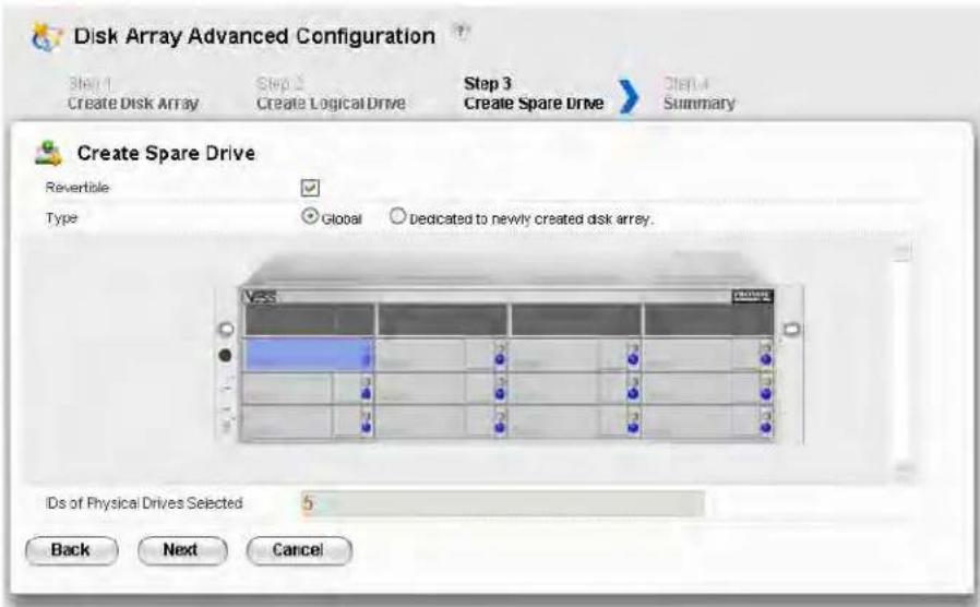
STEP 3 - SPARE DRIVE CREATION
Creating a spare drive is optional but highly recommended.
-
Enter your information and choose your options.
-
Check the Revertible box if you want this spare drive to be revertible.
- Choose the option for the type spare drive you want.
Global – Replaces a failed drive in any disk ar ray.
Dedicated – Replaces the failed drive only in the assigned disk array.
- Click the enclosure graphic to view information about physical drives.
- Click a physical drive to select it for your spare drive.
The physical drive's ID number is added to the Selected list.
- Click the Next button to continue.
STEP 4 - SUMMARY
The Summary screen lists the disk arrays, logical drives, and spare drives that you specified.
If you accept these parameters, click the Submit button.
If you do NOT accept these parameters, review and modify your selections in the previous steps.
ENABLING LUN MAPPING AND MASKING
These features are optional for each logical drive. The Enable LUN Mapping dialog box appears after you create a logical drive.
To enable LUN Mapping:
- Click the OK button in the Enable LUN Mapping dialog box.
The LUN Mapping & Masking screen appears.
-
Check the Enable LUN Masking box to enable LUN Masking.
-
Click the LUN Mapping button to continue.
The initiator list screen displays.
- Choose the initiators you want to use from the drop-down menu and click the Next button.
The screen displays a list of initiators and a list of logical drives.
-
Click and drag a logical drive from the logical drives list to the initiators list.
-
Click the Next button when you are done.
The screen displays a list of initiator IDs and corresponding LUN maps that you specified.
- Click the Submit button to create the LUN map.
The screen displays a list of initiator IDs and corresponding LUN maps.
You can also set LUN mapping and masking at a later time. Click the Administration tab, then click the LUN Mapping & Masking option.
LOGGING OUT OF WEBPAM PROE
There are two ways to log out of WebPAM PROe:
- Close your browser window
- Click Logout on the WebPAM PROe banner
Clicking Logout brings you back to the Login Screen.
After logging out, you must enter your user name and password in order to log in again.
USING WEBPAM PROE OVER THE INTERNET
The above instructions cover connections between Vess R2000 and your company network. It is also possible to connect to a Vess R2000 from the Internet.
Your MIS Administrator can tell you how to access your network from outside the firewall. Once you are logged onto the network, you can access the Vess R2000 using its IP address.
This chapter contains the following topics:
• "Logging into WebPAM PROe" on page 93
- “Choosing the Display Language” on page 94
• "Perusing the Interface" on page 95
• "Logging out of WebPAM PROe" on page 97
• "Viewing the Storage Network" on page 98
• "Managing Subsystems" on page 100
• “Managing RAID Controllers” on page 112
• "Managing Enclosures" on page 123
• “Managing UPS Units” on page 131
• “Managing Network Connections” on page 135
• "Managing Users" on page 137
• "Managing Background Activities" on page 144
• “Managing Storage Services” on page 158
• “Working with the Event Viewer” on page 171
• “Monitoring Performance” on page 175
• "Managing Physical Drives" on page 178
• "Managing Disk Arrays" on page 188
• "Managing Logical Drives" on page 198
• "Managing Spare Drives" on page 213
• “Managing Initiators” on page 219
• "Managing LUNs" on page 223
- “Managing Fibre Channel Connections” on page 227
• “Managing iSCSI Connections” on page 232
LOGGING INTO WEBPAM PROE
-
Launch your browser.
-
In the browser address field, type in the virtual management port IP address of the Vess R2600 subsystem.
Use the IP address you set in the CLI (page 37) or CLU (page 41).
Example:
- WebPAM PROe uses a secure HTTP connection .https://
- Enter the IP address of the Vess R2600 ....
For example, if your Vess R2600 has an IP address: 10.0.0.1 your entry looks like this:
https://10.0.0.1
-
When the login screen appears:
-
Type administrator in the User Name field.
- Type password in the Password field.
- Click the Login button.
The User Name and Password are case sensitive.
- Optional. Choose a display language from the drop-down menu.
WebPAM PROe displays in English, German, French, Italian, Spanish, Russian, Japanese, Traditional Chinese, Simplified Chinese, and Korean.
- Click the Login button.
After login, the WebPAM PROe main menu appears.
CHOOSING THE DISPLAY LANGUAGE
WebPAM PROe displays in multiple languages. You choose the display language when you log in. If you are already logged in and you want to change the display language:
- Click Logout at the top right corner of the screen.
The Login screen appears.
- Click the Language drop-down menu and highlight the language you prefer.
Login language selection menu

- Reenter your user name and password.
- Click the Login button.
WebPAM PROe opens in the language you chose.
PERUSING THE INTERFACE
The WebPAM PROe interface consists of a header and four tabs, each with specific functions.
- Header
Top left corner of the window:
• Name of logged-in user
- IP address – Virtual IP address of the RAID subsystem
• Top right corner of the window
- Save Service Report – Saves a detailed report to your Host PC
- Help – Accesses the Help Welcome screen
- Contact Us – Technical support contact information
- About – Information about WebPAM PROe
- Logout – Exits WebPAM PROe
- Discovery tab
- Displays other PROMISE RAID systems on your network
- Enables direct login to other PROMISE RAID systems
List continues on next page
- Dashboard tab
• RAID subsystem model and type of enclosure
- System status
• Event information – Most recent NVRAM events
- Storage overview – Capacities, number of devices
- Device tab
• Enclosure front and back views
- Topology
• Enclosure component list and settings
• Physical drive management
• UPS (unlimited power supply) management
• Fibre Channel or iSCSI management
- Storage tab
- Wizard – Automatic or Advanced configuration
- Disk array management
• Logical drive management - Initiator management
• LUN mapping and masking
- Administration tab
- Subsystem settings, clearing statistics, NTP, and controller lock
- User management, including LDAP and role mapping
- Software services
• Runtime and NVRAM event logs
• Background activity, settings and schedules - Firmware updates
- Image version
• Performance monitor
• PSU wattage monitor - Restore factory default settings
- Import/Export user database and configuration script
• Network management
Web PAM PROe Main menu/Dashboard
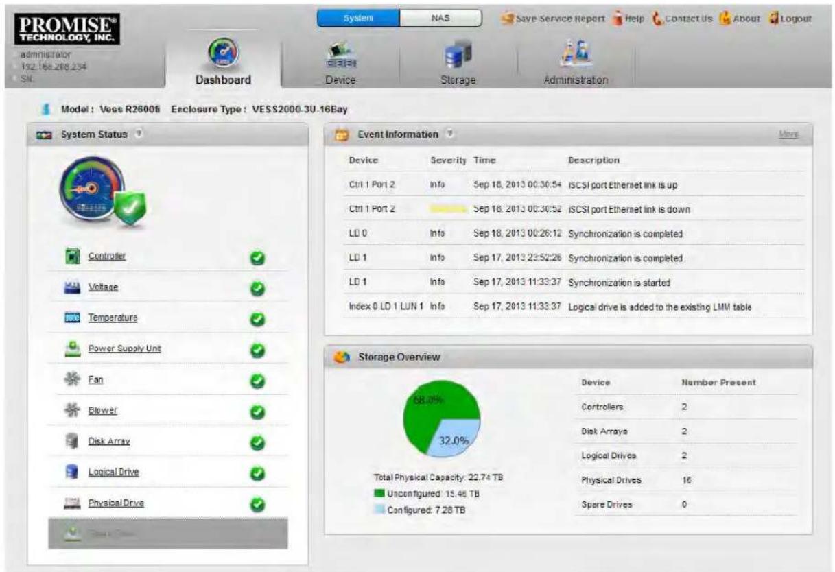
LOGGING OUT OF WEBPAM PROE
There are two ways to log out of WebPAM PROe:
- Close your browser window
- Click Logout on the WebPAM PROe banner
Clicking Logout brings you back to the Login Screen.
After logging out, you must enter your user name and password in order to log in again.
VIEWING THE STORAGE NETWORK
To view the other subsystems on your Storage Network, click the Discovery tab at the left edge of the WebPAM PROe window.
Discovery tab in Main menu
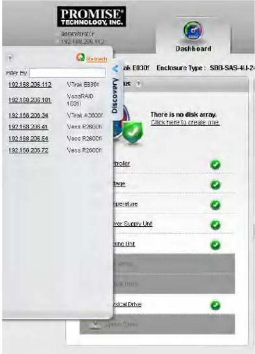
LOGGING ONTO A SUBSYSTEM
To log onto a subsystem in the list, double-click the subsystem.

Caution
The new subsystem displays in the same browser tab. Click your browser's back button to return to the original subsystem.
FILTERING THE SUBSYSTEM LIST
To filter the list, so it shows only specific subsystems, enter a characteristic into the Filter By field and press Enter. To filter by IP address, enter the IP routing prefix for the range you want to display. For example, typing "10.0" in the entry field reveals all subsystems with IP address beginning with the "10.0" prefix.
REFRESHING THE LIST
To refresh the list, click the Refresh link.
MANAGING SUBSYSTEMS
Subsystem management includes:
• "Viewing Subsystem Information" on page 101
- "Making Subsystem Settings" on page 102
- "Locking or Unlocking the Subsystem" on page 102
- "Restoring Factory Default Settings" on page 104
• "Clearing Statistics" on page 105
• "Saving a Service Report" on page 106
- "Importing a Configuration Script" on page 108"
• "Exporting a Configuration Script" on page 109
- "Restarting the Subsystem" on page 110
- "Shutting Down the Subsystem" on page 111
- "Restarting the Subsystem after a Shutdown" on page 111
VIEWING SUBSYSTEM INFORMATION
To view subsystem information, click the Administration tab.
The list of subsystems and host controllers displays.
Subsystem information includes:
| Alias, if assignedModelSerial numberRevision numberNumber of JBOD expansion units connectedNumber of controllers presentRedundancy statusSystem date and time | VendorWWN – World Wide NamePart numberCache Mirroring (Status)Maximum number of JBOD expansion units supportedMaximum number of controllers supportedRedundancy type |
MAKING SUBSYSTEM SETTINGS
To make subsystem settings:
- Click the Administration tab.
- Click the Subsystem Information icon.
-
Click the Settings button.
-
Make changes as required:
-
Enter an alias or change the existing alias in the field provided.
- Choose a redundancy type from the drop-down menu.
The choices are Active-Active and Active-Standby -
Check the box to enable Cache Mirroring (or uncheck to disable)
-
Click the Save button.
LOCKING OR UNLOCKING THE SUBSYSTEM
The lock prevents other sessions (including sessions with the same user) from making a configuration change to the controller until the lock expires or a forced unlock is done. When the user who locked the controller logs out, the lock is automatically released.
SETTING THE LOCK
To set the lock:
- Click the Administration tab.
- Click the Subsystem Information icon.
- Click the Lock / Unlock button.
- In the Lock Time field, type a lock time in minutes.
1440 minutes = 24 hours - Click the Lock button.
RESETTING THE LOCK
To reset the lock with a new time:
- Click the Administration tab.
- Click the Subsystem Information icon.
- Click the Lock / Unlock button.
- In the Lock Time field, type a new lock time in minutes.
1440 minutes = 24 hours - Click the Lock button.
RELEASING THE LOCK
To release a lock that you set:
- Click the Administration tab.
- Click the Subsystem Information icon.
- Click the Lock / Unlock button.
- Click the Unlock button.
RELEASING A LOCK SET BY ANOTHER USER
To release somebody else's lock:
- Click the Administration tab.
- Click the Subsystem Information icon.
- Click the Lock / Unlock button.
- Check the Force Unlock box.
- Click the Unlock button.
RESTORING FACTORY DEFAULT SETTINGS
This feature restores settings to their default values.

Caution
Use this feature only when required and only on the settings that you must reset to default in order to set them correctly.
To restore all settings to their default values:
- Click the Administration tab.
- Click the Restore Factory Default icon.
- In the Restore factory default settings screen, check the boxes beside the settings you want to reset to default value (see Factory Default Settings (by type) table below).
- Click the Submit button.
- In the Confirmation box, type the word "confirm" in the field provided and click the Confirm button.
Factory Default Settings (by type)
Firmware Software NAS
• Background activity settings
- Controller settings
- Enclosure settings
- FC port settings
- iSCSI port settings
• Management network settings
• Physical drive settings
- Subsystem settings
• BGA scheduler settings
• Service settings
- SNMP settings
- Telnet settings
- SSH settings
- Email settings
- Netsend settings
- NTP settings
- User settings
- UPS settings
- Account
- Windows (CIFS)
- UNIX/LINUX (NFS)
• Mac (AFP) - FTP
- WebDAV
- Backup
CLEARING STATISTICS
This function clears statistical data on the RAID controllers, Fibre Channel ports, physical drives, and logical drives.
To clear subsystem statistics:
- Click the Administration tab.
- Click the Subsystem Information icon.
- Click the Clear Statistics button.
- Type the word "confirm" in the field provided.
- Click the Confirm button.
SAVING A SERVICE REPORT
A Service Report is a detailed report covering the configuration and status of all components in your RAID system. A support technician or field engineer might request a service report for the purpose of diagnosis and troubleshooting.
To save a Service Report file:
- Click Save Service Report in the Header (very top of the web interface, next to the Help link).
Information for the report is gathered and compiled. This action takes up to a few minutes, depending on the size of your RAID system - Click the Save File option, then click the Save button.
The report saves to your Host PC as a compressed HTML file. - Double-click the downloaded file to decompress it.
- Double-click the report to open it in your default browser.
The Service Report includes the following topics:
- About – Report utility
- Battery Info – Cache backup batteries
• BBM Info – Bad Block Manager
• BGA Summary – Status and settings
The Service Report includes the following topics:
- BGA Schedules – Scheduled activities
- Buzzer Info
- Controller Info
- Debug Syslog – Diagnostic information
- Disk Array Info – ID, alias, and capacities only
- Disk Array Dump Info – Diagnostic information
- Disk Array Verbose Info – All disk array information
- Enclosure Info
- Error Table Info – Read check, write check, and inconsistent blocks
• Event Info – NVRAM – List of NVRAM events
• Event Info – Runtime – List of Runtime events
- FC Node Info
- FC Device Info
- FC Initiator Info
- FC Port Info
- FC SFP Info
The Service Report includes the following topics, continued:
- FC Stats Info
- Flash Image Version Info
- iSCSI Info
- LDAP Info
- LogDrive Info – Basic logical drive information
- LogDrive Dump Info – Diagnostic information
- Logical Drive Verbose Info – Full logical drive information
- Lunmap Info – LUN map type, LUN masking status, and LUN entries
• Network Info – Virtual port
• Network Maintenance Info – Maintenance mode ports - Phydriv Info – Basic physical drive information
• Phydriv Verbose Info – Full physical drive information - PD SMART Info – Physical drive ID, model, type, and SMART status
- PSU Wattage Info – Enclosure power consumption, power supply input and output, and power on time
- SWMGT Info – Software management
• Service Setting – Email
• Service Setting – Netsend
• Service Setting – NTP
• Service Setting – SLP
• Service Setting – SNMP
• Service Setting – SSH
• Service Setting – Telnet
- Sessions Info
- Spare Info – Basic spare drive information
- Spare Dump Info – Diagnostic information
- Spare Verbose Info – Full spare drive information
- Statistic Info
- Subsystem info
- UPS Info
- User Info
IMPORTING A CONFIGURATION SCRIPT
You can write a CLI configuration script to automatically configure your Vess R2600 subsystem. The script must be a plain, non-encrypted text file. From there, you can import the script from the Host PC and perform the configuration automatically.

Cautions
Do NOT attempt to write or modify a configuration script until you receive guidance from Technical Support.
Importing a configuration script overwrites the current settings on your Vess R2600 subsystem.
Or you can save the configuration from one Vess R2600 RAID subsystem, export it, and then automatically configure your other Vess R2600 RAID subsystems. To import a configuration script:
- Click the Administration tab.
- Click the Import/Export icon.
- Click the Import option.
- Choose Configuration Script from the Type drop-down menu.
- Click the Browse button and navigate to the configuration script and click the OK button.
- Click the Next button.
The system verifies that the file is a valid configuration script and displays any errors or warnings. - Click the Submit button to continue.
- In the Confirmation box, type the word "confirm" in the field provided and click the Confirm button. The configuration script is imported and applied automatically.
EXPORTING A CONFIGURATION SCRIPT
You can save the configuration from one Vess R2600 RAID subsystem, export it, and then import it to automatically configure your other Vess R2600 RAID subsystems.
To export a configuration script:
- Click the Administration tab.
- Click the Import/Export icon.
- Click the Export option.
- Choose Configuration Script from the Type drop-down menu.
- Click the Submit button.
- In the Open dialog box, click the Save File option, then click the OK button.
The file is saved to your PC as "Configscript.txt".

Cautions
Do NOT attempt to write or modify a configuration script until you receive guidance from Technical Support.
RESTARTING THE SUBSYSTEM
This function shuts down the subsystem and then restarts it.
To restart the subsystem:
- Click the Administration tab.
- Click the Subsystem Information icon.
- Choose the option to apply the restart to the Subsystem, Controller 1 only or Controller 2 only.
- Click the Shutdown/ Restart button.
- Click the Restart button.
- Type the word "confirm" in the field provided.
- Click the Confirm button.
When the controller shuts down, your WebPAM PROe connection is lost.
- Wait at least two minutes.
- In your browser, click Logout in the WebPAM PROe Header, then log in again.
If you cannot log in immediately, wait 30 seconds and try again.
SHUTTING DOWN THE SUBSYSTEM
This function shuts down the RAID subsystem without restarting it.
To shutdown the subsystem:
- Click the Administration tab.
- Click the Subsystem Information icon.
- Choose the option to apply the shutdown to the Subsystem, Controller 1 only or Controller 2 only
- Click the Shutdown/ Restart button.
- Click the Shutdown button.
- Type the word "confirm" in the field provided.
- Click the Confirm button.
When the controller shuts down, your WebPAM PROe connection is lost. - Wait at least two minutes.

Important
If your RAID subsystem manages JBOD expansion units, you must follow the proper startup procedure.
RESTARTING THE SUBSYSTEM AFTER A SHUTDOWN
To start the RAID subsystem:
- Press the Power button on the front left side of the device being restarted.
- Wait at least two minutes.
- Open your browser and log into WebPAM PROe.
If you cannot log in immediately, wait 30 seconds and try again.
MANAGING RAID CONTROLLERS
RAID controller management includes:
• "Viewing Controller Information" on page 113
• "Making Controller Settings" on page 114
• "Viewing Controller Statistics" on page 116
- “Locating a Controller” on page 117
- "Updating Firmware on a RAID Subsystem" on page 118
• "Reconditioning a Battery" on page 121
• "Viewing Battery Information" on page 120
• "Buzzer Settings" on page 122
• "Silencing the Buzzer" on page 122
VIEWING CONTROLLER INFORMATION
To view controller information:
- Click the Device tab.
- Click the Component List icon.
- Click the controller you want, then click the View button.
Controller information includes:
- Controller ID
- Readiness Status
- Power On Time
• LUN Mapping method - Serial Number
- Hardware Revision
- Cache Usage – Percentage
- Boot Loader Version
- Firmware Build Date
- Software Build Date
- Alias – If assigned
- Operational Status
• SCSI Protocol Supported - Part Number
- WWN – World Wide Name
- Dirty Cache Usage – Percentage
- Firmware Version
- Software Version
4. Click the Advanced Information tab.
Advanced controller information includes:
| Slot 1 Memory Type | Slot 1 Memory Size |
| Slot 2 Memory Type | Slot 2 Memory Size |
| LUN Affinity * | ALUA * |
| Controller Role | Flash Type |
| Flash Size | NVRAM Type |
| NVRAM Size | Preferred Cache Line Size |
| Coercion * | Coercion Method * |
| SMART * | SMART Polling Interval * |
| Write Back Cache Flush Interval * | Enclosure Polling Interval * |
| Adaptive Writeback Cache * | Host Cache Flushing * |
| Forced Read Ahead (cache) * | Power Saving Idle Time * |
| Power Saving Standby Time * | Power Saving Stopped Time * |
| Cache Line Size | Advanced Battery Flash Backup Enabled * |
| Backup Flash Status | Backup Flash Size |
| Perfect Rebuild Available | Appliance Mode |
Items with an asterisk (*) are adjustable under Controller Settings.
MAKING CONTROLLER SETTINGS
In a dual-controller RAID subsystem, settings made to one controller are applied to both controllers.
To make controller settings:
- Click the Device tab.
- Click the Component List icon.
- Click the controller you want, then click the Settings button.
4. Make settings changes as required:
- Enter, change or delete the alias in the Alias field.
- LUN Affinity – Choose an enable/disable option from the drop-down menu. RAID controllers must be set to Active-Active.
- ALUA – Choose an enable/disable option from the drop-down menu. RAID controllers must be set to Active-Active. See Making Subsystem Settings and "ALUA"
- SMART Log – Check the box to enable or uncheck to disable.
• SMART Polling Interval – Enter a value into the field, 1 to 1440 minutes - HDD Power Saving – Choose time periods from the drop-down menus. After an HDD has been idle for the set period of time:
Power Saving Idle Time – Parks the read/write heads.
Power Saving Standby Time – Lowers disk rotation speed.
Power Saving Stopped Time - Spins down the disk (stops rotation).
- Coercion – Check the box to enable or uncheck to disable.
- Coercion Method – Choose a method from the drop-down menu:
GBTruncate
10GBTruncate
GrpRounding
TableRounding
- Write Back Cache Flush Interval – Enter a value into the field, 1 to 12 seconds.
• Enclosure Polling Interval – 15 to 255 seconds. - Adaptive Writeback Cache – Check the box to enable or uncheck to disable. See “Adaptive Writeback Cache” on page 591.
- Host Cache Flushing – Check the box to enable or uncheck to disable. See “Host Cache Flushing” on page 592.
- Forced Read Ahead (cache) – Check the box to enable or uncheck to disable. See “Forced Read-Ahead Cache” on page 590.
- Advanced Battery Flash Backup - Check the box to enable or uncheck to disable.
5. Click the Save button.

Notes
Power Management must be enabled on the disk array for the HDD Power Saving settings to be effective. See "Making Disk Array Settings"
Power Management functions are limited to the features your HDDs actually support.
VIEWING CONTROLLER STATISTICS
To view controller statistics:
- Click the Device tab.
- Click the Component List icon.
- Click the controller you want, then click the View button.
- Click the Statistics tab.
Controller statistics include:
• Data Transferred
- Read Data Transferred
- Errors
- Read Errors
- I/O Requests
- Read IO Requests
• Statistics Start Time
• Write Data Transferred
• Non-Read/Write Errors
- Write Errors
• Non-Read/Write Requests
- Write I/O Requests
• Statistics Collection Time

Note
To clear controller statistics, see "Clearing Statistics" on page 105.
LOCATING A CONTROLLER
This feature causes the controller LEDs to blink for one minute to assist you in locating the controller on a RAID subsystem or JBOD expansion unit.
To locate a controller:
- Click the Device tab.
- Click the Component List icon.
- Click the controller you want, then click the Locate button.
The controller status LEDs blink for one minute.
VIEWING THE FLASH IMAGE INFORMATION
To view the flash image information for the RAID subsystem enclosure:
- Click the Administration tab.
- Click the Image Version icon.
- Click the Enclosure you want to See and click the triangular button.
RAID subsystems have the following components in their flash image:
- Kernel
- 6G Expander
- Firmware
- System Libraries
- Software
- Applications
- Ramdisk
- Mount Scripts
- SEP Firmware
- PLX EEPROM Image
- OEM Customization
- SAS Expander
- BIOS
-
NASAPP
-
Running – The version that is currently running on the subsystem or expansion unit.
- Flashed – This version was updated but does not run until the subsystem restarts.
See "Updating Firmware on a RAID Subsystem" on page 118
JBOD expansion units have only one component in their flash image, SEP firmware. It only appears as running.
UPDATING FIRMWARE ON A RAID SUBSYSTEM
Use this function to flash (update) the firmware on the Vess R2600.
Download the latest firmware image file from PROMISE support:
http://www.promise.com/support/ and save it to your Host PC or TFTP server.

Important
Verify that no background activities are running on the RAID subsystem.
To update the firmware on the RAID subsystem and JBOD expansion units:
- Click the Administration tab.
- Click the Firmware Update icon.
- Click the Controller Firmware Update tab.
The Controller Firmware Update screen appears showing the current Image Version Number and Build Date.
-
Choose a download option:
-
Local File through HTTP – Click the Browse button, locate the firmware image file, click the file to choose it, then click the Open button.
-
TFTP Server – Enter the TFTP Server host name or IP address, port number and file name.
-
Optional. Check the Non-disruptive Image Update (NDIU) box.
NDIU updates the RAID controllers and I/O modules one at a time, enabling I/O operations continue during the firmware update. Updates with this option take a longer period of time to complete. Only dual controller models support this feature.
- Click the Next button.
The next screen shows the Flash Image (firmware image file) Version Number and Build Date.
- Click the Submit button.
The progress of the update displays.

Warning
Do NOT power off the RAID subsystem during the update!
Do NOT move to any other screen until the firmware update operation is completed!
When the update is completed a message tells you to reboot the subsystem,
-
Click the OK button.
-
If you chose the Disruptive Flash Method, the RAID subsystem and JBOD expansion units automatically restart.
- If you chose the Non-Disruptive Flash Method, the system automatically flashes and restarts the RAID controllers one at a time.
AUTOMATIC RESTART
If you did NOT check the NDIU box, the RAID subsystem and JBOD expansion units automatically restart. That action temporarily disrupts I/O operations and drops your WebPAM PROe connection.
To reestablish your WebPAM PROe connection:
- Wait no less than two minutes.
- Click Logout in the WebPAM PROe Header, then log in again.
If you cannot log in, wait 30 seconds and try again. - In your browser, click Logout in the WebPAM PROe Header, then log in again.
If you cannot log in immediately, wait 30 seconds and try again.
VIEWING BATTERY INFORMATION
Batteries maintain power to the controller cache in the event of a power failure, thus protecting any data that has not been written to a physical drive.
To view battery information:
- Click the Device tab.
-
Click the Component List icon.
-
Click the battery you want, then click the View button.
Battery information includes:
- Battery ID
- Operational status – Fully charged, recondition means a reconditioning is in process
- Battery chemistry – LiON, etc.
- Remaining capacity – Battery capacity as a percentage
- Battery cell type – Number of cells
- Estimated hold time – Time in hours that the battery can power the cache
- Estimated backup cycle - For Advanced Battery Flash Backup, this is the number of times the Write Cache can be saved from DRAM to Flash memory given current battery capacity remaining.
- Temperature threshold discharge – Maximum temperature allowed when the battery is discharging
- Temperature threshold charge – Maximum temperature allowed when the battery is charging
- Battery temperature – Actual battery temperature
- Cycle count – Number of times the battery was reconditioned
• Voltage in millivolts - Current in milliamps
RECONDITIONING A BATTERY
Batteries maintain power to the controller cache in the event of a power failure, thus protecting any data that has not been written to a physical drive. Reconditioning is the action of discharging and recharging a battery to preserve its capacity and performance.
Reconditioning is a background activity, it might affect I/O performance. When the recondition is completed, the battery's cycle count increments by one.
Battery reconditioning is disabled by default. You can change the reconditioning status and schedule.
To recondition a battery immediately:
- Click the Device tab.
- Click the Component List icon.
- Click the battery you want, then click the Recondition button.
Battery operations status changes to “Recondition” and the battery’s remaining capacity and estimated hold time fall and rise reflecting the discharge and recharge cycles of the reconditioning. That behavior is normal.
MAKING SCHEDULE CHANGES
To make changes the scheduled battery reconditioning:
- Click the Administration tab.
-
Click the Background Activities icon.
The list of Background Activities displays. -
Click the Scheduler button.
-
Mouse-over Battery Reconditioning and click the Settings button.
-
Make settings changes as required:
-
Start Time
- Uncheck the Enable This Schedule box to disable this activity.
- Recurrence Pattern
- Start From
-
End On
-
Click the Save button to apply the new settings.
BUZZER SETTINGS
To make buzzer settings:
- Click the Device tab.
- Click the Component List icon.
- Click the Buzzer and click the Settings button.
- Check the Enable Buzzer box to enable the buzzer, or uncheck the box to disable.
- Click the Save button.
This action disables the buzzer for all events.
To silence the buzzer:
- Click the Device tab.
- Click the Component List icon.
- Click the Buzzer and click the Settings button.
- Uncheck the Enable Buzzer box.
- Click the Save button.

Note
The alarm can also be muted by pressing the Mute Alarm button on the front left side of the Vess R2600 unit.
MANAGING ENCLOSURES
Enclosure management includes the following functions:
• "Viewing Enclosure Topology" on page 124
• "Viewing the Enclosures Summary" on page 126
• “Making Enclosure Settings” on page 127
• "Locating an Enclosure" on page 126
• "Viewing FRU VPD Information" on page 128
• "Viewing Power Supply Status" on page 128
• "Viewing Cooling Unit Status" on page 129
• "Viewing Temperature Sensor Status" on page 129
• "Viewing Voltage Sensor Status" on page 130
VIEWING ENCLOSURE TOPOLOGY
This feature displays the connection topology of the Vess R2600 subsystem. Topology refers to the manner in which the data paths among the enclosures are connected. There are three methods:
- Individual Subsystem – A single subsystem
- JBOD Expansion – Managed through one subsystem or head unit
- RAID Subsystem Cascading – Managed through one subsystem or head unit
To view enclosure topology:
- Click the Device tab.
- Click the Topology icon.
The topology or data connections of your system displays. (See example on next page)
Topology display

flowchart
graph TD
    A["Enclosure 1\n(Head Unit)\nVESS2000-3U-16Bay"] --> B["Node 1"]
    A --> C["Node 2"]
    A --> D["Node 3"]
    A --> E["Node 4"]
    A --> F["Node 5"]
    style A fill:#f9f,stroke:#333
    style B fill:#ccf,stroke:#333
    style C fill:#ccf,stroke:#333
    style D fill:#ccf,stroke:#333
    style E fill:#ccf,stroke:#333
    style F fill:#ccf,stroke:#333
VIEWING THE ENCLOSURES SUMMARY
Enclosure Management includes information, status, settings and location. To access Enclosure Management:
-
Click the Device tab.
-
Click the Component List icon.
The following information is shown:
• Enclosure ID number
- Status
- Enclosure Type
- Status Description (specific components in need of attention, if any)
To locate an enclosure:
- Click the Device tab.
- Click the Component List icon.
- Click the Enclosure you want, then click the Locate button.
The enclosure LEDs blink for one minute.
VIEWING ENCLOSURE INFORMATION
To view enclosure information:
- Click the Device tab.
-
Click the Component List icon.
-
Click the Enclosure and click the View button.
Enclosure information includes:
- Enclosure ID
- Enclosure Type
• Enclosure Warning Temperature Threshold
• Controller Warning Temperature Threshold
• Max Number of Controllers
• Max Number of Fans
• Max Number of Temperature Sensors
• Max Number of Batteries
• Enclosure Critical Temperature Threshold
• Controller Critical Temperature Threshold
• Max Number of Physical Drive Slots
• Max Number of Blowers
• Max Number of Power Supply Units
• Max Number of Voltage Sensors
For information on Enclosure problems, See "Enclosure Problems" on page 623.
MAKING ENCLOSURE SETTINGS
To make Enclosure settings:
- Click the Device tab.
- Click the Component List icon.
- Click the Enclosure and click the Settings button.
Enclosure settings include:
• Enclosure Warning Temperature Threshold [56-60]°C
• Enclosure Critical Temperature Threshold [61-73]°C
• Controller Warning Temperature Threshold [76-80]°C
• Controller Critical Temperature Threshold [81-85]°C
- In the field provided, type the temperature in degrees C for each threshold value.
- Click the Save button.
VIEWING FRU VPD INFORMATION
FRU VPD refers to Vital Product Data (VPD) information about Field Replaceable Units (FRU) in the enclosure. The number and type of FRU depends on the subsystem model.
To view FRU VPD information:
- Click the Device tab.
- Click the Component List icon.
- Click the Enclosure and click the FRU VPD button.
Use this information when communicating with Technical Support and when ordering replacement units.
For contact information, See "Contacting Technical Support" on page 58.
VIEWING POWER SUPPLY STATUS
To view the status of the power supplies and the fans that cool those power supplies:
- Click the Device tab.
- Click the Component List icon.
- Click the Enclosure and click the View button.
- Scroll down to view the power supplies.
The screen displays the operational and fan status of the power supplies. If any status differs from normal or the fan speed is below the Healthy Threshold value, a malfunction is indicated in the Status column.
See "Replacing a Power Supply" on page 58.
VIEWING COOLING UNIT STATUS
To view the status of the cooling units:
- Click the Device tab.
- Click the Component List icon.
- Click the Enclosure and click the View button.
- Scroll down to view the Blowers.
The screen displays the status and speed of the cooling units. If blower speed is below the Healthy Threshold, a malfunction is indicated in the Status column. See "Enclosure Problems" on page 623.
VIEWING TEMPERATURE SENSOR STATUS
To view the status of the temperature sensors:
- Click the Device tab.
- Click the Component List icon.
- Click the Enclosure and click the View button.
- Scroll down to view the Temperature Sensors.
If any temperature exceeds the Healthy Threshold value, an overheat condition exists in the enclosure. See "Making Enclosure Settings" and "Enclosure Problems" on page 623.
VIEWING VOLTAGE SENSOR STATUS
To view the status of the voltage sensors:
- Click the Device tab.
- Click the Component List icon.
- Click the Enclosure and click the View button.
- Scroll down to view the Voltage Sensors.
If any voltage is outside the Healthy Threshold values, a voltage malfunction in the enclosure is indicated in the Status column. See "Enclosure Problems" on page 623.
MANAGING UPS UNITS
Uninterruptible Power Supply (UPS) Management includes the following functions:
• "Viewing a List of UPS Units" on page 131
• "Viewing UPS Information" on page 134
VIEWING A LIST OF UPS UNITS
To view a list of UPS units supporting the Vess R2600:
- Click the Device tab.
- Click the UPS icon.
Information in the UPS List includes:
• ID – The ID number of the UPS
• Status – OK means Normal.
On AC means the UPS is connected to a viable external AC power source.
On Battery means the external AC power source is offline and the UPS is running on battery power.
• Model – Model name of the UPS
- Battery Capacity – Backup capacity expressed as a percentage.
- Loading Ratio – Actual output of UPS as a percentage of the rated output. See the Note below.
- Remaining Minutes – Number of minutes the UPS is expected to power your system in the event of a power failure.

Note
The maximum recommended Loading Ratio varies among models of UPS units. The general range is 60% to 80%. If the reported Loading Ratio exceeds the recommended value for your UPS unit:
Have fewer subsystems or peripherals connected to this UPS unit.
Add more UPS units, or use a higher-capacity UPS unit, to protect your RAID systems.
MAKING UPS SETTINGS
These settings control how the Vess R2600 subsystem detects the UPS unit and responds to data reported by the UPS unit.
To make UPS settings:
- Click the Device tab.
- Click the UPS icon.
-
Click the UPS Settings button.
-
Perform the following actions as required:
- Verify the Current UPS Communication method. See Note 1:
SNMP – Network connection.
USB
Unknown – No connection.
- Choose a Detection Setting from the drop-down menu:
Automatic – Default. If a UPS is detected when the subsystem boots, the settings changes to Enable.
Enable – Monitors UPS. Settings changes, reports warnings, and logs events.
Disable – Does not monitor UPS.
- Type values into the Threshold fields. See Note 2:
Running Time Remaining Threshold – Actual time below this value resets adaptive writeback cache to writethrough.
Warning Temperature Threshold – Actual temperature above this value triggers a warning and logs an event.
Loading Ratio Threshold – Actual loading ratio (percentage) above this threshold triggers a warning and logs an event. See Note 3.
- For UPS units with network cards, type the IP addresses or DNS names in fields UPS 1 and UPS 2. See Note 4.
- Press Submit to save your settings.
Note 1: Vess R2600 supports multiple UPS units using network or USB connections, but not a combination
of both methods.
Note 2: Detection Setting must be set to Auto. If a UPS is detected, the settings changes to Enable.
Note 3: The maximum recommended Loading Ratio varies among models of UPS units. The general range is 60% to 80%.
Note 4: To specify UPS units by DNS names, ask your IT administrator to add the DNS names to the DNS server, before you make UPS settings.
VIEWING UPS INFORMATION
To view information about a specific UPS unit:
- Click the Device tab.
- Click the UPS icon.
- Mouse-over UPS and click the View button.
UPS information includes:
- UPS ID
- Model Name
- Serial Number
- Firmware Version
• Manufacture Date
• Voltage Rating – Output voltage of the UPS. - Battery Capacity – Backup capacity expressed as a percentage.
- Remaining Backup Time – Number of minutes the UPS is expected to power your system in the event of a power failure.
- Loading Ratio – Actual output of UPS as a percentage of the rated output. See the Note below.
• Temperature – Reported temperature of the UPS unit.

Note
The maximum recommended Loading Ratio varies among models of UPS units. The general range is 60% to 80%. If the reported Loading Ratio exceeds the recommended value for your UPS unit:
Have fewer subsystems or peripherals connected to this UPS unit.
Add more UPS units, or use a higher-capacity UPS unit, to protect your RAID systems.
MANAGING NETWORK CONNECTIONS
Network Connections Management includes the following functions:
- “Making Virtual Management Port Settings” on page 135
- "Making Maintenance Mode Settings" on page 136
MAKING VIRTUAL MANAGEMENT PORT SETTINGS
The Vess R2600 subsystem has a virtual management port, enabling you to log into a Vess R2600 with dual controllers using one IP address.
Before you change settings, please See "About IP Addresses" on page 36.
You initially made these settings during subsystem setup. You can change them later as required.

Caution
Changing virtual management port settings can interrupt your WebPAM PROe connection and require you to log in again.
To make virtual management port settings:
- Click the Administration tab.
- Click the Network Management icon.
- Click the Virtual Management Port tab.
- Click the protocol family whose settings you want to change and click the Configuration button.
-
Make the following settings are needed:
-
Check the Enable box to enable this protocol family.
- Check the Enable DHCP box to enable a DHCP server to make your network settings. DHCP is currently supported in IPv4 only.
-
For manual network settings, type the RAID subsystem's IP address, subnet mask, gateway IP address, and DNS server IP address into the fields provided.
-
Click the Submit button.
MAKING MAINTENANCE MODE SETTINGS
Each controller has its own IP addresses for access when the controller goes into maintenance mode.
Before you change settings, please See "About IP Addresses" on page 68.
To make maintenance mode settings:
- Click the Administration tab.
- Click the Network Management icon.
- Click the Maintenance Mode tab.
- Click the controller and protocol family whose settings you want to change and click the Configuration button.
-
Make the following settings are needed:
-
Check the Enable box to enable this protocol family.
- Check the Enable DHCP box to enable a DHCP server to make your network settings. DHCP is currently supported in IPv4 only.
-
For manual network settings, type the IP address, subnet mask, gateway IP address, and DNS server IP address into the fields provided.
-
Click the Submit button.
MANAGING USERS
User management includes:
• "Viewing User Information" on page 137
- “Creating a User” on page 138
• "Making User Settings" on page 139
- “Changing User Passwords” on page 140
• "Deleting a User" on page 141
- "Setting User Event Subscriptions" on page 141
- "Importing a User Database" on page 142
• "Exporting a User Database" on page 143
The Administrator or a Super User can perform these tasks.
VIEWING USER INFORMATION
To view user information:
- Click the Administration tab.
- Click the User Management icon.
The list of users displays. User information includes:
- User name
- Status
- Privilege level
- Display name
- Email address
CREATING A USER
This action requires Administrator or Super User privileges.
To create a user:
- Click the Administration tab.
- Click the User Management icon.
-
Click the Add User button.
-
In the Add User dialog box, enter the information in the fields provided:
-
Name – This is the user's login name
- Display Name
- Password
- Retype Password
-
User Email – Required for event notification
-
Choose a privilege level from the drop-down menu. See the table below for a description of the privilege types.
-
(Optional) Uncheck the Enable box to disable this User account.
-
Click the Save button. The user is added to the list.

Important
For this user to receive event notification, Click the new user and click the Subscription button.
| User Privileges | |
| Level | Meaning |
| View | Allows the user to See all status and settings but not to make any changes |
| Maintenance | Allows the user to perform maintenance tasks including Rebuilding, PDM, Media Patrol, and Redundancy Check |
| Power | Allows the user to create (but not delete) disk arrays and logical drives, change RAID levels, change stripe size; change settings of components such as disk arrays, logical drives, physical drives, and the controller |
| Super | Allows the user full access to all functions including create and delete users and changing the settings of other users, and delete disk arrays and logical drives. The default “administrator” account is a Super User |
MAKING USER SETTINGS
This action requires Administrator or a Super User privileges.
To make user settings:
- Click the Administration tab.
- Click the User Management icon.
- In the User list, click the user you want, then click Settings.
-
Make settings changes as required:
-
For the Enable box, check to enable this user account, uncheck to disable this user account
• In the User Settings dialog box, enter a new Display Name or User Email address -
Choose a new Privilege level from the drop-down menu. See the table on the next page.
-
Click the Save button.
CHANGING USER PASSWORDS
This action requires Administrator or Super User privileges.
To change a user's password:
- Click the Administration tab.
- Click the User Management icon.
- In the User list, click the user you want, then click Change Password.
- In the Change Password dialog box, enter the information in the fields provided:
- New Password
-
Retype Password
-
Click the Save button.
DELETING A USER
This action requires Administrator or Super User privileges
To delete a user:
- Click the Administration tab.
- Click the User Management icon.
- In the User list, click the user you want, then click the Delete button.
- In the Confirmation box, type the word "confirm" in the field provided and click the Confirm button.
SETTING USER EVENT SUBSCRIPTIONS
By default, all users have event notification:
- Enabled
- Set to the Major (severity) level for all events
Subscribing users receive notification of events at the chosen severity level and all higher levels.

Note
Each user must have a valid Email address to receive events. See “Making User Settings” below.
Changing a user subscription requires Administrator or Super User privileges.
To set a user event subscription:
- Click the Administration tab.
- Click the User Management icon.
- In the User list, click the user you want, then click the Subscription button.
-
Make settings changes as required:
-
For the Enable Event Notification box, check to enable for this user, uncheck to disable.
-
Click to change the priority options for each category of event.
-
Click the Save button.
IMPORTING A USER DATABASE
You can save the user information and settings from one Vess R2600 RAID subsystem, export it, and then import it to automatically configure your other Vess R2600 RAID subsystems.

Caution
Importing a user database overwrites the current users and user settings on your Vess R2600 subsystem.
To import a user database:
- Click the Administration tab.
- Click the Import/Export icon.
- Click the Import option.
- Choose User Database from the Type drop-down menu.
- Click the Browse button and navigate to the user database file and click the OK button.
- Click the Next button.
The system verifies that the file is a valid user database and displays any errors or warnings.
-
Click the Submit button to continue.
-
In the Confirmation box, type the word "confirm" in the field provided and click the Confirm button.
The user database is imported and applied automatically.
EXPORTING A USER DATABASE
You can save the user information and settings from one Vess R2600 RAID subsystem, export it, and then import it to automatically configure your other Vess R2600 RAID subsystems.
To export a user database:
-
Click the Administration tab.
-
Click the Import/ Export icon.
-
Click the Export option.
-
Choose User Database from the Type drop-down menu.
-
Click the Submit button.
-
In the Opendialog box, click the Save File option, then click the OK button.
The file is saved to your PC as "User.dat".

Note
The user database file is not designed to be opened or edited in the field.
MANAGING BACKGROUND ACTIVITIES
Background activity management includes:
• "Viewing Current Background Activities" on page 145
- "Viewing Scheduled Background Activities" on page 145
- "Adding a Scheduled Background Activity" on page 145
- “Changing a Background Activity Schedule” on page 147
- "Enabling or Disabling a Scheduled Background Activity" on page 148
- "Deleting a Scheduled Background Activity" on page 149
• "Media Patrol" on page 150
• "Redundancy Check" on page 151
- "Initialization" on page 152
- "Rebuild" on page 153
- "Migration" on page 154
- "PDM" on page 155
- "Transition" on page 156
• "Synchronization" on page 157
• "Battery Reconditioning" on page 157
Background activities perform a variety of preventive and remedial functions on your physical drives, disk arrays, logical drives, and other components.
You can run a background activity immediately or schedule it to run at a later time. Scheduling options are described below.
Setting options for each activity are listed after the scheduling options. These settings determine how the background activity affects I/O performance.
VIEWING CURRENT BACKGROUND ACTIVITIES
To view a list of current background activities:
- Click the Administration tab.
- Click the Background Activities icon.
The list of background appears.
Currently running activities show a progress bar.
VIEWING SCHEDULED BACKGROUND ACTIVITIES
To view a list of scheduled background activities:
- Click the Administration tab.
- Click the Background Activities icon.
The list of background appears. - Click the Scheduler button.
The list of currently scheduled background activities appears.
Adding a Scheduled Background Activity
To add a new scheduled background activity:
- Click the Administration tab.
- Click the Background Activities icon.
The list of background appears. -
Click the Scheduler button.
The list of currently scheduled background activities appears. -
Click the Add Schedule button.
-
Check the Enable Media Patrol box to enable, uncheck to disable.
This settings enables or disables Media Patrol for your entire RAID system.
-
Click the Confirm button.
-
Choose the option for the activity you want:
-
Media Patrol
- Redundancy Check
- Spare Check
-
Battery Recondition
-
Choose a Start Time from the drop-down menus.
The menus have a 24-hour clock.
-
Choose a Recurrence Pattern option, daily, weekly, or monthly.
-
For the Daily option, enter an interval in the Every field.
- For the Weekly option, enter an interval in the Every field and choose one or more days of the week.
-
For the Monthly option, choose, Day of the Month option then choose a number from the drop-down menu. The day of the week option then choose the day of the month from the drop-down menus.
-
Choose a Start From date from the drop-down menus.
-
Choose an End On option,
• No end date or perpetual.
• End after a specific number of activity actions.
• Until date from the drop-down menus.
-
For Redundancy Check, choose,
-
Auto Fix option – Attempts to repair the problem when it finds an error. Check to enable
- Pause on Error option – The process stops when it finds a non-repairable error. Check to enable
-
Select LD – Check the boxes for the logical drives to run Redundancy Check. Check at least one logical drive
-
Click the Save button.
CHANGING A BACKGROUND ACTIVITY SCHEDULE
To change an existing scheduled background activity:
- Click the Administration tab.
- Click the Background Activities icon.
The list of background appears.
- Click the Scheduler button.
The list of currently scheduled background activities appears.
-
Click the background activity and click the Settings button.
-
Make settings changes as required:
-
Choose a Start Time from the drop-down menus.
The menus have a 24-hour clock.
- Choose a Recurrence Pattern option, daily, weekly, or monthly.
For the Daily option, enter an interval in the Every field.
For the Weekly option, enter an interval in the Every field and choose one or more days of the week.
For the Monthly option, choose the Day of the Month option or the day of the week option, and choose the day from the drop-down menu.
- Choose a Start From date from the drop-down menus.
- Choose an End On option,
No end date or perpetual.
End after a specific number of activity actions.
Until date from the drop-down menus.
• For Redundancy Check, choose,
Auto Fix option – Attempts to repair the problem when it finds an error. Check to enable
Pause on Error option – The process stops when it finds a non-repairable error.
Check to enable
Select LD – Check the boxes for the logical drives to run Redundancy Check. Check at least one logical drive
- Click the Save button.
ENABLING OR DISABLING A SCHEDULED BACKGROUND ACTIVITY
Background activity schedules are enabled by default when you create the schedule. If you want to stop a background activity now but plan to use it again in the future, disable the scheduled activity rather than deleting it.
To enable or disable change an existing scheduled background activity:
- Click the Administration tab.
- Click the Background Activities icon.
The list of background appears.
- Click the Scheduler button.
The list of currently scheduled background activities appears.
- Click the background activity and click the Settings button.
- Uncheck the Enable This Schedule box to disable this schedule.
Check the box to enable this schedule.
- Click the Save button.
DELETING A SCHEDULED BACKGROUND ACTIVITY
To change an existing scheduled background activity:
- Click the Administration tab.
- Click the Background Activities icon.
The list of background appears. - Click the Scheduler button.
The list of currently scheduled background activities appears. - Click the background activity and click the Delete button.
- In the confirmation box, click the confirm button.
MEDIA PATROL
Media Patrol is a routine maintenance procedure that checks the magnetic media on each disk drive. Media Patrol checks are enabled by default on all disk arrays and spare drives. Media Patrol is concerned with the media itself, not the data recorded on the media. If Media Patrol encounters a critical error, it triggers PDM if PDM is enabled on the disk array.
See "Making Disk Array Settings" on page 193.
MAKING MEDIA PATROL SETTINGS
To make Media Patrol settings:
- Click the Administration tab.
-
Click the Background Activities icon.
The list of background appears. -
Click the Settings button.
-
Check the Enable Media Patrol box to enable, uncheck to disable.
This settings enables or disables Media Patrol for your entire RAID system.
- Click the Confirm button.
You can also enable or disable Media Patrol on individual disk arrays.
REDUNDANCY CHECK
Redundancy Check is a routine maintenance procedure for fault-tolerant disk arrays (those with redundancy) that ensures all the data matches exactly. Redundancy Check can also correct inconsistencies. See “Redundancy Check on a Logical Drive” on page 208.
MAKING REDUNDANCY CHECK SETTINGS
To make Redundancy Check settings:
- Click the Administration tab.
- Click the Background Activities icon.
The list of background activities appears.
-
Click the Settings button.
-
Click the Redundancy Check Rate drop-down menu and choose a rate:
-
Low – Fewer system resources to Redundancy Check, more to data read/write operations.
- Medium – Balances system resources between Redundancy Check and data read/write operations.
-
High – More system resources to Redundancy Check, fewer to data read/write operations.
-
Click the Confirm button.
INITIALIZATION
Technically speaking, Initialization is a foreground activity, as you cannot access a logical drive while it is initiating.
Initialization is normally done to logical drives after they are created from a disk array. Initialization sets all data bits in the logical drive to zero. The action is useful because there may be residual data on the logical drives left behind from earlier configurations. For this reason, Initialization is recommended whenever you create a logical drive. See “Initializing a Logical Drive” on page 207.
MAKING INITIALIZATION SETTINGS
To make initialization settings:
- Click the Administration tab.
- Click the Background Activities icon.
-
Click the Settings button.
-
Click the Logical Drive Initialization Rate drop-down menu and choose a rate:
-
Low – Fewer system resources to Initialization, more to data read/write operations.
- Medium – Balances system resources between Initialization and data read/write operations.
-
High – More system resources to Initialization, fewer to data read/write operations.
-
Click the Confirm button.
REBUILD
When you rebuild a disk array, you are actually rebuilding the data on one physical drive.
- When a physical drive in a disk array fails and a spare drive of adequate capacity is available, the disk array begins to rebuild automatically using the spare drive.
- If there is no spare drive of adequate capacity, but the Auto Rebuild function is ENABLED, the disk array begins to rebuild automatically as soon as you remove the failed physical drive and install an unconfigured physical drive in the same slot. See “Making Rebuild Settings” below.
- If there is no spare drive of adequate capacity and the Auto Rebuild function is DISABLED, you must replace the failed drive with an unconfigured physical drive, then perform a Manual Rebuild.
See "Rebuilding a Disk Array" on page 196 and "Spare Drives" on page 581.
Also see "Disk Array Degraded / Logical Drive Critical" on page 633 and "Disk Array Offline / Logical Drive Offline" on page 634.
MAKING REBUILD SETTINGS
- Click the Administration tab.
- Click the Background Activities icon.
The list of background activities appears.
- Click the Settings button.
-
Click the Rebuild Rate drop-down menu and choose a rate:
-
Low – Fewer system resources to the Rebuild, more to data read/write operations.
• Medium – Balances system resources between the Rebuild and data read/write operations. -
High – More system resources to the Rebuild, fewer to data read/write operations.
-
Check the Enable Auto Rebuild box to enable Auto Rebuild (rebuilds when you swap out the failed drive with a new one).
-
Click the Confirm button.
MIGRATION
The term "Migration" means either or both of the following:
- Change the RAID level of a logical drive.
- Expand the storage capacity of a logical drive.
See “Migrating a Logical Drive’s RAID Level” on page 209 and “RAID Level Migration” on page 570.
MAKING MIGRATION SETTINGS
To make migration settings:
- Click the Administration tab.
- Click the Background Activities icon.
The list of background activities appears.
- Click the Settings button.
-
Click the Migration Rate drop-down menu and choose a rate:
-
Low – Fewer system resources to Migration, more to data read/write operations.
• Medium – Balances system resources between Migration and data read/write operations. -
High – More system resources to Migration, fewer to data read/write operations.
-
Click the Confirm button.
PDM
Predictive Data Migration (PDM) is the migration of data from the suspect physical drive to a spare drive, similar to rebuilding a logical drive. But unlike Rebuilding, PDM constantly monitors your physical drives and automatically copies your data to a spare drive before the physical drive fails and your logical drive goes Critical.
See "Running PDM on a Disk Array" on page 195 and "PDM" on page 551.
MAKING PDM SETTINGS
To make PDM settings:
- Click the Administration tab.
- Click the Background Activities icon.
The list of background activities appears.
-
Click the Settings button.
-
Make the following settings are required:
-
Click the PDM Rate drop-down menu and choose a rate:
Low – Fewer system resources to PDM, more to data read/write operations.
Medium – Balances system resources between PDM and data read/write operations.
High – More system resources to PDM, fewer to data read/write operations. -
Highlight the current values in the block threshold fields and input new values.
Reassigned block threshold range is 1 to 512 blocks.
Error block threshold range is 1 to 2048 blocks. -
Click the Confirm button.
TRANSITION
Transition is the process of replacing a revertible spare drive that is currently part of a disk array with an unconfigured physical drive or a non-revertible spare drive.
See "Running a Transition on a Spare Drive" on page 218.
MAKING TRANSITION SETTINGS
To make Transition settings:
- Click the Administration tab.
- Click the Background Activities icon.
The list of background activities appears.
- Click the Settings button.
- Click the Transition Rate drop-down menu and choose a rate:
- Low – Fewer system resources to Transition, more to data read/write operations.
• Medium – Balances system resources between Transition and data read/write operations.
- High – More system resources to Transition, fewer to data read/write operations.
- Click the Confirm button.
SYNCHRONIZATION
Synchronization is automatically applied to redundant logical drives when they are created. Synchronization recalculates the redundancy data to ensure that the working data on the physical drives is properly in sync.
Mouse-over on the logical drive, click the View button, and look under Logical Drive Information beside the line that says Synchronized. A Yes means the logical drive was synchronized. See “Viewing Logical Drive Information” on page 199.
MAKING SYNCHRONIZATION SETTINGS
To make Synchronization settings:
- Click the Administration tab.
- Click the Background Activities icon.
The list of background activities appears.
-
Click the Settings button.
-
Click the Synchronization Rate drop-down menu and choose a rate:
-
Low – Fewer system resources to Synchronization, more to data read/write operations.
• Medium – Balances system resources between Synchronization and data read/write operations. -
High – More system resources to Synchronization, fewer to data read/write operations.
-
Click the Confirm button.
BATTERY RECONDITIONING
Batteries maintain power to the controller cache in the event of a power failure, thus protecting any data that has not been written to a physical drive. Reconditioning is the action of discharging and recharging a battery to preserve its capacity and performance.
MANAGING STORAGE SERVICES
Storage service management includes:
• "Viewing a List of Services" below
• "Email Service" on page 159
• "Telnet Service" on page 161
• "SSH Service" on page 163
• "SNMP Service" on page 165
• "Netsend Service" on page 168
VIEWING A LIST OF SERVICES
This feature displays all software services running on the RAID subsystem.
To view the list of software services:
- Click the Administration tab.
- Click the Services icon.
The Services list displays the Status and Start Type of the services available. These services are described in the sections that follow.
EMAIL SERVICE
Email service enables the RAID subsystem to send you Email messages about events and status changes. By default, Email service is set to Automatic.
STOPPING EMAIL SERVICE
To stop the Email service:
- Click the Administration tab.
- Click the Services icon.
- Click the Email service and click the Stop button.
- Click the Confirm button.
To start the Email service after stopping it:
- Click the Administration tab.
- Click the Services icon.
- Click the Email service and click the Start button.
RESTARTING EMAIL SERVICE
To restart the Email service:
- Click the Administration tab.
- Click the Services icon.
- Click the Email service and click the Restart button.
MAKING EMAIL SETTINGS
To change Email service settings:
- Click the Administration tab.
- Click the Services icon.
-
Click the Email service and click the Settings button.
-
Make settings changes as required:
- Choose a startup type,
Automatic – (default) Starts and runs with the subsystem.
Manual – You start the service when you need it.
- SMTP Server IP address.
- SMTP Authentication – The Yes option enables authentication. The No option disables.
- SMTP Authentication Username – Required if SMTP authentication is enabled.
- SMTP Authentication Password – Required if SMTP authentication is enabled.
- Email Sender (From) Address – The sender's name shown on notification messages.
-
Email Subject – The subject line of the notification message.
-
Click the Save button.
-
Click the Confirm button.

Note
To verify your settings, send a test message.
TELNET SERVICE
Telnet service enables you to access the RAID subsystem's Command Line Interface (CLI) through a network connection.
STOPPING TELNET SERVICE
To stop the Telnet service:
- Click the Administration tab.
- Click the Services icon.
- Click Telnet service and click the Stop button.
- Click the Confirm button.
To start the Telnet service after stopping it:
- Click the Administration tab.
- Click the Services icon.
- Click Telnet service and click the Start button.
RESTARTING TELNET SERVICE
To restart the Telnet service:
- Click the Administration tab.
- Click the Services icon.
- Click Telnet service and click the Restart button.
MAKING TELNET SETTINGS
To change Telnet service settings:
- Click the Administration tab.
- Click the Services icon.
-
Click Telnet service and click the Settings button.
-
Make settings changes as required:
-
Choose a startup type,
Automatic – Starts and runs with the subsystem.
Manual – (default) You start the service when you need it. -
Port number – Default is 2300.
- Max Number of Concurrent Connections – Default is 4. Maximum number is 4.
-
Session Time Out – Default is 24 minutes.
-
Click the Save button.
-
Click the Confirm button.
SSH SERVICE
Secure Shell (SSH) service enables you to access the subsystem's Command Line Interface (CLI) through a network connection.
STOPPING SSH SERVICE
To stop SSH service:
- Click the Administration tab.
- Click the Services icon.
- Click SSH service and click the Stop button.
- Click the Confirm button.
To start SSH service after stopping it:
- Click the Administration tab.
- Click the Services icon.
- Click SSH service and click the Start button.
RESTARTING SSH SERVICE
To restart SSH service:
- Click the Administration tab.
- Click the Services icon.
- Click SSH service and click the Restart button.
MAKING SSH SETTINGS
To change SSH service settings:
- Click the Administration tab.
- Click the Services icon.
-
Click the SSH service and click the Settings button.
-
Make settings changes as required:
-
Choose a startup type,
Automatic - (default) Starts and runs with the subsystem.
Manual – You start the service when you need it.
• Port number - Default is 22.
- Max Number of Concurrent Connections – Default is 4.
Maximum number is 4.
- Session Time Out - Default is 24 minutes.
-
Click the Save button.
-
Click the Confirm button.
SNMP SERVICE
Simple Network Management Protocol (SNMP) service enables the SNMP browser to obtain information from the RAID subsystem. The Trap Sink is where SNMP events are sent and can be viewed.
STOPPING SNMP SERVICE
To stop the SNMP service:
- Click the Administration tab.
- Click the Services icon.
- Click SNMP service and click the Stop button.
- Click the Confirm button.
To start the SNMP service after stopping it:
- Click the Administration tab.
- Click the Services icon.
- Click SNMP service and click the Start button.
RESTARTING SNMP SERVICE
To restart the SNMP service:
- Click the Administration tab.
- Click the Services icon.
- Click the SNMP service and click the Restart button.
MAKING SNMP SETTINGS
To change SNMP service settings:
- Click the Administration tab.
- Click the Services icon.
-
Click the SNMP service and click the Settings button.
-
Make settings changes as required:
-
Choose a startup type,
Automatic - (default) Starts and runs with the subsystem.
Manual – You start the service when you need it. -
Port Number – Default is 161.
- System Name – No default.
- System Location – Default is USA.
- System Contact – Default is admin@yourcompany.com.
- Read Community – Default is public.
-
Write Community – Default is private. No changes are possible.
-
Click the Save button.
-
Click the Confirm button.
ADDING AN SNMP TRAP SINK
To add a trap sink:
- Click the Administration tab.
- Click the Services icon.
- Click SNMP service and click the Settings button.
- Enter a trap sink server IP address in the field provided.
- Choose a trap filter (event severity level). See "Event Severity Levels" on page 170.
- Click the Add button.
- Click the Confirm button.
DELETING AN SNMP TRAP SINK
To delete a trap sink:
- Click the Administration tab.
- Click the Services icon.
- Click SNMP service and click the Settings button.
- In the Trap Sink list and click the Trap Sink you want to delete.
- Click the Trash icon.
The trap sink is deleted.
-
Click the Save button.
-
Click the Confirm button.
NETSEND SERVICE
Netsend service sends RAID subsystem events in the form of text messages to the Host PC and other networked PCs configured to receive Netsend event messages by setting up Netsend server accounts.
This service is set to Manual startup by default. It does not run unless you start it manually or change the startup type to Automatic.
STARTING NETSEND SERVICE
To restart the Netsend service:
- Click the Administration tab.
- Click the Services icon.
- Click the Netsend service and click the Start button.
STOPPING NETSEND
To stop the Netsend service:
- Click the Administration tab.
- Click the Services icon.
- Click the Netsend service and click the Stop button.
- Click the Confirm button.
RESTARTING NETSEND SERVICE
To start the Netsend service after stopping it:
- Click the Administration tab.
- Click the Services icon.
- Click the Netsend service and click the Start button.
MAKING NETSEND SETTINGS
To change Netsend service settings:
- Click the Administration tab.
- Click the Services icon.
- Click the Netsend service and click the Settings button.
- Choose a startup type,
• Automatic – Starts and runs with the subsystem.
- Manual – (default) You start the service when you need it.
-
Click the Save button.
-
Click the Confirm button.
Adding Netsend Server Accounts
To add a Netsend server account:
- Click the Administration tab.
- Click the Services icon.
- Click the Netsend service and click the Settings button.
- Enter the recipient server IP address in the field provided.
- Choose a recipient filter (event severity level). See "Event Severity Levels" on page 170.
-
Click the Add button.
The recipient server is added to the list. -
Click the Save button.
-
Click the Confirm button.
| Event Severity Levels | |
| Level | Description |
| Fatal | Non-recoverable error or failure has occurred. |
| Critical | Action is needed now and the implications of the condition are serious. |
| Major | Action is needed now. |
| Minor | Action is needed but the condition is not a serious at this time. |
| Warning | User can decide whether or not action is required. |
| Information | Information only, no action is required. |
DELETING NETSEND SERVER ACCOUNTS
To delete a Netsend server account:
- Click the Administration tab.
- Click the Services icon.
- Click the Netsend service and click the Settings button.
- In the Message Event Severity Filter list, click the recipient server you want to delete.
- Click the Trash icon.
The recipient server is deleted. - Click the Save button.
- Click the Confirm button.
WORKING WITH THE EVENT VIEWER
Working with the Event Viewer includes the following functions:
• "Viewing Runtime Events" on page 172
• "Saving Runtime Events" on page 172
• “Clearing Runtime Events” on page 173
• "Viewing NVRAM Events" on page 173
• "Saving NVRAM Events" on page 174
• "Clearing NVRAM Events" on page 174
The Event Viewer displays log of subsystem events. Events are classified as:
- Runtime Events – A list of and information about the 1023 most recent runtime events recorded since the subsystem was started.
- NVRAM Events – A list of and information about the most important events over multiple subsystem startups. NVRAM events are stored in non-volatile memory.
| Event Severity Levels | |
| Level | Description |
| Fatal | Non-recoverable error or failure has occurred. |
| Critical | Action is needed now and the implications of the condition are serious. |
| Major | Action is needed now. |
| Minor | Action is needed but the condition is not a serious at this time. |
| Warning | User can decide whether or not action is required. |
| Information | Information only, no action is required. |
VIEWING RUNTIME EVENTS
To display Runtime Events:
- Click the Administration tab.
- Click the Events icon.
The log of Runtime Events appears. Events are added to the top of the list. Each item includes:
- Index number – Begins with 0 at system startup.
• Device – Disk Array, Logical Drive, Physical Drive by its ID number.
• Event ID – Hexadecimal code for the specific event
• Severity – see table on previous page -
Timestamp – Date and time the event happened.
• Description – A description of the event in plain language. -
Press the up and down arrow keys to scroll through the log.
SAVING RUNTIME EVENTS
This feature saves a plain text file of runtime events to your host PC or server using your browser.
To save the Runtime Events log:
- Click the Administration tab.
- Click the Events icon.
- Click the Save button.
- Follow your browser's procedure to save the event file to the desired location.
CLEARING RUNTIME EVENTS
To clear the Runtime Events log:
- Click the Administration tab.
- Click the Events icon.
- Click the Clear button.
- In the Confirmation box, type the word "confirm" in the field provided and click the Confirm button.
VIEWING NVRAM EVENTS
This screen displays a list of and information about the most important events over multiple subsystem startups.
To display NVRAM events:
- Click the Administration tab.
- Click the Events icon.
- Click the NVRAM Events button.
The log of NVRAM Events appears. Events are added to the top of the list. Each item includes:
- Index number – Begins with 0 at system startup.
• Device – Disk Array, Logical Drive, Physical Drive by its ID number.
• Event ID – Hexadecimal code for the specific event - Severity – See . "Event Severity Levels" on page 171.
-
Timestamp – Date and time the event happened.
• Description – A description of the event in plain language. -
Press the up and down arrow keys to scroll through the log.
SAVING NVRAM EVENTS
This feature saves a plain text file of NVRAM events to your host PC or server using your browser.
To save NVRAM Events:
- Click the Administration tab.
- Click the Events icon.
- Click the NVRAM Events button.
-
Click the Save button.
-
Follow your browser's procedure to save the event file to the desired location.
CLEARING NVRAM EVENTS
To clear the Runtime Events log:
- Click the Administration tab.
- Click the Events icon.
- Click the Clear button.
- In the Confirmation box, type the word "confirm" in the field provided and click the Confirm button.
MONITORING PERFORMANCE
Performance monitoring includes:
• "Monitoring I/O Performance" below
• "Monitoring PSU Wattage" on page 177
MONITORING I/O PERFORMANCE
The Performance Monitor displays real-time performance statistics for logical drives, physical drives, and Fibre Channel or iSCSI data ports. The vertical scale adjusts dynamically to accommodate the statistical data.
Because it reports performance in real-time, to see data in the monitor, there must be I/O data activity taking place between the Vess R2600 subsystem and the Host.
To monitor performance:
- Click the Administration tab.
- Click the Performance Monitor icon. Follow the instructions below for the menu category you want to view.
Logical Drive
- Under Logical Drive, choose the metric you want to see from the Measurement drop-down menu.
• Bandwidth in MB/s
- Cache usage by %
- Dirty cache usage by %
• Maximum latency in ms
• Average latency in ms
• Minimum latency in ms
- I/Os per second
- Click the Select Logical Drives button and check the boxes for the logical drives you want to see.
• Total of all logical drives
- Up to 8 individual logical drives
Physical Drive
- Under Physical Drive, choose the metric you want to see from the Measurement drop-down menu.
• Bandwidth in MB/s
• Maximum latency in ms
• Average latency in ms
• Minimum latency in ms
- I/Os per second
- Click the Select Physical Drives button and check the boxes for the physical drives you want to see.
• Total of all physical drives
- Up to 8 individual physical drives
Port
- Under Port, choose the metric you want to see from the Measurement drop-down menu.
• Bandwidth in MB/s
• Maximum latency in ms
• Average latency in ms
• Minimum latency in ms
- I/Os per second
- Click the Select Ports button and check the boxes for the ports you want to see:
• Total of all ports
- Up to 8 individual ports
NAS
Under NAS, choose the metric you want to see from the Measurement drop-down menu.
• Bandwidth in MB/s
• Maximum latency in ms
• Average latency in ms
• Minimum latency in ms
- I/Os per second
Since the Performance Monitor is a real-time display, it does not accumulate information and there is no clear or save function.
To save performance statistics for analysis or troubleshooting, save a Service Report, open the report, and look under Statistic Info.
MONITORING PSU WATTAGE
The PSU Wattage Monitor displays real-time performance statistics for logical drives, the input power of all enclosures and the input power of an individual. The vertical scale adjusts dynamically to accommodate the statistical data.
Because it reports performance in real-time, to see data in the monitor, there must be I/O data activity taking place between the Vess R2600 subsystem and the Host.
To monitor performance and power use:
- Click the Administration tab.
- Click the PSU Wattage Monitor icon.
- Under Input Power of an individual Enclosure, click the Select Enclosures button and check the boxes for the enclosures you want to see.
Since the PSU Wattage Monitor is a real-time display, it does not accumulate information and there is no clear or save function.
To save performance and power statistics for analysis or troubleshooting, save a Service Report, open the report, and look under PSU Wattage Info.
MANAGING PHYSICAL DRIVES
Physical drive management includes:
For physical disk troubleshooting, see "Physical Drive Problems" on page 632.
• "Viewing a List of Physical Drives" on page 179
• Viewing "Viewing Physical Drive Information" on page 179
- "Making Global Physical Drive Settings" on page 181
- "Making Individual Physical Drive Settings" on page 182
• "Viewing Physical Drive Statistics" on page 183
• "Viewing Physical Drive SMART Log Information" on page 184
- "Saving the Physical Drive SMART Log" on page 185
- "Locating a Physical Drive" on page 185
• "Forcing a Physical Drive Offline" on page 186
- “Clearing a Stale or a PFA Condition” on page 187
- "Updating Firmware on a Physical Drive" on page 187
VIEWING A LIST OF PHYSICAL DRIVES
To view a list of physical drives in the RAID system:
- Click the Device tab.
- Click the Physical Drive icon.
The list of enclosures and the physical drives inside them displays.
Physical drive information includes:
• ID – ID number of the physical drive
- Status – Green check , yellow ! , and red X icons
- Model – Make and model of the drive
- Type – SAS or SATA, HDD or SSD
- Location – Enclosure number and slot number
- Configuration – Array number and sequence number, spare number, unconfigured, or stale configuration
- Capacity – In GB
VIEWING PHYSICAL DRIVE INFORMATION
To view physical drive information:
- Click the Device tab.
- Click the Physical Drive icon.
3. Click the physical drive you want, then click the View button.
Physical drive information includes:
• Model - Model of PROMISE system
• Physical Drive ID – ID number of the physical drive
- Location – Enclosure number and slot number
- Alias – If assigned
• Physical Capacity – Total capacity in GB
- Configurable Capacity – Usable capacity in GB
• Used Capacity – Capacity actually used in GB
- Block Size – Typically 512 Bytes
- Operational Status – OK is normal, Stale, PFA, Dead
- Configuration – Array number and sequence number, spare number, Model – Make and model of the drive
- Drive Interface – SATA 1.5Gb/s or 3Gb/s, SAS 3Gb/s or 6Gb/s
- Serial Number – Serial number of the drive
- Firmware Version – Firmware version on the drive
- Protocol Version – ATA/ATAPI or SCSI protocol version
- Visible To – Controllers that can access this physical drive
Advanced information for SATA physical drives includes:
- Write Cache – Enabled or disabled
- Read Look Ahead Cache – Enabled or disabled
- Read Cache Support – Yes or No
• SMART Feature Set – Yes or No
• SMART Self Test – Yes or No
• SMART Error Logging – Yes or No - Command Queuing Support – TCQ or NCQ
-
Command Queuing – Enabled or disabled
-
Queue Depth - Number of commands
• Maximum Multiple DMA Mode Supported
• Maximum Ultra DMA Mode Supported - DMA Mode
• Power Saving Level – Enabled or disabled - APM Support – Standby or Active
• Medium Error Threshold - Drive Temperature
• Drive Reference Temperature
Advanced information for SAS physical drives includes:
- Read Cache – Enabled or disabled
- Read Cache Support – Yes or No
- Write Cache – Enabled or disabled
• Write Cache Support – Yes or No - Enable Read Look Ahead Support – Yes or No
- Read Look Ahead Cache – Enabled or disabled
- Command Queuing – Enabled or disabled
• Command Queuing Support – Yes or No -
WWN – World Wide Name
• Port 1 Negotiated Physical Drive Speed -
Port 1 SAS Address
• Port 2 Negotiated Physical Drive Speed - Port 2 SAS Address
- Drive Temperature in ^
• Drive Reference Temperature in °C
• Power Saving Level – Enabled or disabled
• Medium Error Threshold
• SAS SATA Bridge Firmware Version
• SAS SATA Bridge Boot Loader Version
MAKING GLOBAL PHYSICAL DRIVE SETTINGS
To make global physical drive settings:
- Click the Device tab.
- Click the Physical Drive icon.
- Click the Global Physical Drive Settings button.
- Check the boxes to enable, uncheck to disable.
For SATA drives:
- Enable Write Cache
- Enable Read Look Ahead Cache
- Enable Command Queuing
For SAS drives:
- Enable Write Cache
- Enable Read Look Ahead Cache
-
Enable Read Cache
-
Click the Save button.
MAKING INDIVIDUAL PHYSICAL DRIVE SETTINGS
To make individual physical drive settings:
- Click the Device tab.
- Click the Physical Drive icon.
- Click the physical drive you want, then click the Settings button.
- On the Settings tab:
- Enter, change, or delete the alias in the Alias field.
- On the SMART Log Settings tab:
- Check the box to enable the SMART log.
- Click the Save button.
VIEWING PHYSICAL DRIVE STATISTICS
To view physical drive statistics:
- Click the Device tab.
- Click the Physical Drive icon.
- Click the physical drive you want, then click the View button.
- Click the Statistics tab.
Physical drive statistics include
- Data Transferred
- Read Data Transferred
• Write Data Transferred - Errors - Number of errors
• Non Read/Write Errors - Read Errors
- Write Errors
• I/O Request – Number of requests
• Non Read/Write Request – Number of requests - Read I/O Request – Number of requests
• Write I/O Request – Number of requests
• Statistics Start Time – Time and date
• Statistics Collection Time – Time and date
- Avg Response Time Ctrl 1 – Controller 1 average response time
- Avg Response Time Ctrl 2 – Controller 2 average response time
- Max Response Time Ctrl 1 – Controller 1 maximum response time
- Max Response Time Ctrl 2 – Controller 2 maximum response time
To clear physical drive statistics, see "Clearing Statistics" on page 105.
VIEWING PHYSICAL DRIVE SMART LOG INFORMATION
To view physical drive SMART Log information:
- Click the Device tab.
- Click the Physical Drive icon.
- Click the physical drive you want, then click the View button.
- Click the SMART Log tab.
SMART Log information includes:
- In progress
• SMART Support – Yes or no, depends on the drive - SMART Log Enabled – Enabled or disabled, (If the SMART Log is disabled, see "Making Controller Settings" on page 114.)
• SMART Health status – OK is normal - SCT Status Version
- SCT Version
- SCT Support Level
-
Device State
-
Current Temperature
• Power Cycle Min Temperature
• Power Cycle Max Temperature
• Lifetime Min Temperature
• Lifetime Max Temperature
• Under Temperature Limit Count
• Over Temperature Limit Count
SAVING THE PHYSICAL DRIVE SMART LOG
To save the physical drive SMART Log:
- Click the Device tab.
- Click the Physical Drive icon.
- Click the physical drive you want, then click the View button.
- Click the SMART Log tab.
- Click the Save Advanced SMART Log button.
Your browser saves a text file containing the SMART Log to its designated download folder.
LOCATING A PHYSICAL DRIVE
This feature causes the drive carrier LEDs to blink for one minute to assist you in locating the physical drive, and is supported by RAID subsystems and JBOD expansion units.
To locate a physical drive:
- Click the Device tab.
- Click the Physical Drive icon.
- Click the physical drive you want, then click the Locate button.
The drive carrier status LED flashes for one minute.
This feature applies only to physical drives assigned to disk arrays.

Caution
Forcing a physical drive offline is likely to cause data loss. Back up your data before you proceed. Use this function only when required.

Important
Forcing a physical drive offline causes your logical drives to become degraded. If Auto Rebuild is enabled and a spare drive is available, the disk array begins rebuilding itself automatically.
To force a physical drive offline:
- Click the Device tab.
- Click the Physical Drive icon.
- Click the down arrow button to list the physical drives in the enclosure.
- Mouse over the physical drive you want to force offline.
- Click the Force Offline button.
- In the Confirmationbox, type the word "confirm" in the field provided and click the Confirm button.
CLEARING A STALE OR A PFA CONDITION
This procedure is used to clear configuration data on a physical drive; or if the physical drive is stale or the has errors putting it in PFA status.
Stale - The physical drive contains obsolete disk array information.
PFA – The physical drive has errors resulting in a prediction of failure.
Be sure you have corrected the condition by a physical drive replacement, rebuild operation, etc., first. Then clear the condition.
To clear a Stale or a PFA condition:
- Click the Device tab.
- Click the Physical Drive icon.
- Click the physical drive you want, then click the Clear button.
If the physical drive has both a Stale condition and a PFA condition, the first click removes the Stale condition. Click the Clear button a second time to remove the PFA condition.
UPDATING FIRMWARE ON A PHYSICAL DRIVE
This feature applies only to PROMISE-supported physical drives. For a list of supported drives, go to http://www.promise.com/support/.
If you have physical drives in your RAID system that are not PROMISE-supported, follow the firmware update procedure from the drive manufacturer.
MANAGING DISK ARRAYS
For disk array troubleshooting, see "Disk Array and Logical Drive Problems" on page 633.
Disk array management includes:
• "Viewing a List of Disk Arrays" on page 188
- “Creating a Disk Array Manually” on page 190
- “Creating a Disk Array with the Wizard” on page 191
• "Deleting a Disk Array" on page 192
• "Making Disk Array Settings" on page 193
- “Running PDM on a Disk Array” on page 195
• "Preparing a Disk Array for Transport" on page 196
• "Rebuilding a Disk Array" on page 196
VIEWING A LIST OF DISK ARRAYS
To view a list of disk arrays:
- Click the Storage tab.
- Click the Disk Array icon.
The list of disk arrays appears.
Disk array information includes:
• ID – DA0, DA1, DA2, etc.
- Alias – If assigned
- Status – A green check 📊 icon means OK
• Capacity – Data capacity of the array
• Free Capacity – Unconfigured or unused capacity on the physical drives
• Media Patrol – Enabled or disabled on this array
• No. of Logical Drives – The number of logical drives on this array
VIEWING DISK ARRAY INFORMATION
To view disk array information:
-
Click the Storage tab.
-
Click the Disk Array icon.
The list of disk arrays appears.
- Click the disk array you want, then click the View button.
Array information displays, including:
• ID – DA0, DA1, DA2, etc.
- Alias – If assigned
• Operational Status – OK is normal
• Media Patrol – Enabled or disabled on this array
- PDM – Enabled or disabled on this array
• Total Physical Capacity – Data capacity of the array
- Configurable Capacity – Maximum usable capacity of the array
• Free Capacity –Unconfigured or unused capacity on the physical drives
• Max Contiguous Free Capacity - The largest contiguous free capacity available.
• Current Power Saving Level - Default is disabled
• Number of Physical Drives – The number of physical drives in this array
• Number of Logical Drives – The number of logical drives on this array
- Max Contiguous Free Capacity – Unconfigured or unused capacity in contiguous sectors on the physical drives
• Available RAID Levels – RAID levels you can specify on this array
DISK ARRAY OPERATIONAL STATUS
- OK – This is the normal state of a logical drive. When a logical drive is Functional, it is ready for immediate use. For RAID Levels other than RAID 0 (Striping), the logical drive has full redundancy.
- Synchronizing – This condition is temporary. Synchronizing is a maintenance function that verifies the integrity of data and redundancy in the logical drive. When a logical drive is Synchronizing, it functions and your data is available. However, access is slower due to the synchronizing operation.
- Critical/Degraded – This condition arises as the result of a physical drive failure. A degraded logical drive still functions and your data is still available. However, the logical drive has lost redundancy (fault tolerance). You must determine the cause of the problem and correct it.
- Rebuilding – This condition is temporary. When a physical drive has been replaced, the logical drive automatically begins rebuilding in order to restore redundancy (fault tolerance). When a logical drive is rebuilding, it functions and your data is available. However, access is slower due to the rebuilding operation.
- Transport Ready – After you perform a successful Prepare for Transport operation, this can means you can remove the physical drives of this disk array and move them to another enclosure or different drive slots. After you relocate the physical drives, the disk array status shows OK.
CREATING A DISK ARRAY MANUALLY
This feature creates a disk array only. You can also use the Wizard to create a disk array with logical drives and spare drives at the same time.
This action requires Super User or Power User privileges.
To create a disk array:
- Click the Storage tab.
- Click the Disk Array icon.
-
Click the Create Disk Array button.
-
Accept the defaults or make changes:
-
Enter an alias in the Alias field
Maximum of 32 characters; letters, numbers, space between characters, and underline.
• Media Patrol – Uncheck to disable on this array. - PDM – Uncheck to disable on this array.
• Power Management – Uncheck to disable on this array. - Choose a media type – Hard disk drive (HDD) or solid state drive (SSD)

Important
All physical drives in an array must be the same media type, i.e. all HDD or all SDD.
- In the Select Physical Drives diagram, click the drives to add them to your array. Look for drives with a green LED dark, a blue LED lit, and no crosshatching over the carrier.
The ID numbers of the chosen drives appear in the field below the diagram.
- When you have finished your settings and choices, click the Submit button.
The new array appears in the list.
If you are done creating disk arrays, click the Finish button.
To create additional disk arrays, click the Create More button.
After you create a disk array, create a logical drive on it. See “Creating a Logical Drive Manually” on page 203.
CREATING A DISK ARRAY WITH THE WIZARD
The Wizard creates disk arrays and logical drives automatically. It has four options.
• Automatic – Creates a new disk array following a default set of parameters. Creates a hot spare drive
for all RAID levels except RAID 0, when five or more unconfigured physical
can accept or reject the proposed arrangement but you cannot modify it. See instructions in "Automatic
Configuration" on page 86.
- Advanced – Enables you to specify all parameters for a new disk array, logical drives and spare drives.
See instructions in "Advanced Configuration" on page 87.
DELETING A DISK ARRAY

Caution
If you delete a disk array, you also delete any logical drives that belong to it, along with the data in those logical drives. Back up any important data before deleting a disk array.
This action requires Administrator or Super User privileges.
To delete a disk array:
- Click the Storage tab.
- Click the Disk Array icon.
- Click the disk array you want, then click the Delete button.
- In the Confirmation box, type the word "confirm" in the field provided and click the Confirm button.
This feature causes the drive carrier LEDs to flash for one minute to assist you in locating the physical drives that make up this disk array.
To locate a disk array:
- Click the Storage tab.
- Click the Disk Array icon.
The list of disk arrays appears.
- Click the disk array you want, then click the Locate button.
The drive carrier status LEDs for the array flash for one minute.
Drive carrier status LED

MAKING DISK ARRAY SETTINGS
To make disk array settings:
- Click the Storage tab.
- Click the Disk Array icon.
The list of disk arrays appears.
- Click the disk array you want, then click the Settings button.
- Make settings changes as required:
- Enter, change or delete the alias in the Alias field Maximum of 32 characters; letters, numbers, space between characters, and underline.
• Media Patrol – Check to enable, uncheck to disable on this array.
- PDM – Check to enable, uncheck to disable on this array.
- Power Management – Check to enable, uncheck to disable on this array.
- Click the Save button.

Notes
You can also enable or disable Media Patrol for the entire RAID system. See “Making Media Patrol Settings” on page 150.
HDD Power Saving must be enabled on the RAID controller for the Power Management settings to be effective. See “Making Controller Settings” on page 114.
Power Management functions are limited to the features your HDDs actually support.
RUNNING MEDIA PATROL ON A DISK ARRAY
Media Patrol is a routine maintenance procedure that checks the magnetic media on each disk drive. If Media Patrol encounters a critical error, it triggers PDM if PDM is enabled on the disk array.
For more information, see “Media Patrol” on page 550 and “PDM” on page 551.
To run Media Patrol:
- Click the Administration tab.
-
Click the Background Activities icon.
The list of background activities appears. -
Mouse-over Media Patrol and click the Start button.
STOPPING, PAUSING OR RESUMING MEDIA PATROL
To stop, pause or resume Media Patrol:
- Click the Administration tab.
- Click the Background Activities icon.
The list of background appears.
- Mouse-over Media Patrol and click the Stop, Pause or Resume button.
RUNNING PDM ON A DISK ARRAY
Predictive Data Migration (PDM) is the migration of data from the suspect disk drive to a spare disk drive.
For more information, see "PDM" on page 551.
RUNNING PDM
To run PDM on a disk array:
- Click the Administration tab.
-
Click the Background Activities icon.
The list of background activities appears. -
Mouse-over PDM and click the Start button.
-
From the Source Physical Drive drop-down menu, choose a Source disk array and physical drive.
-
From the Target Physical Drive drop-down menu, choose a Target physical drive.
-
Click the Confirm button.
STOPPING, PAUSING OR RESUMING PDM
To stop, pause or resume PDM:
- Click the Administration tab.
- Click the Background Activities icon.
The list of background activities appears. - Mouse-over PDM and click the Stop, Pause, or Resume button.
You can also enable or disable PDM on individual disk arrays. See "Making Disk Array Settings" on page 193.
PREPARING A DISK ARRAY FOR TRANSPORT
This feature prepares the physical drives that make up the disk array to be removed from the enclosure and installed in a different location.
To prepare a disk array for transport:
- Click the Storage tab.
- Click the Disk Array icon.
The list of disk arrays appears.
- Click the disk array you want, then click the Transport button.
- Click the Confirm button.
The status changes to Transport Ready.
- Remove the physical drives and install them in their new location.
For more information, see "Installing Physical Drives" on page 35.
REBUILDING A DISK ARRAY
When you rebuild a disk array, you are actually rebuilding the data on one physical drive.
If there is no spare drive of adequate capacity and the Auto Rebuild function is DISABLED, you must replace the failed drive with an unconfigured physical drive, then perform a Manual Rebuild. See “Making Rebuild Settings” on page 153.

Important
If your replacement disk drive was formerly part of a different disk array or logical drive, you must clear the configuration data on the replacement drive before you use it. See “Clearing a Stale or a PFA Condition” on page 187.
PERFORMING A MANUAL REBUILD
To perform a manual rebuild:
- Click the Administration tab.
-
Click the Background Activities icon.
The list of background activities appears. -
Mouse-over Rebuild and click the Start button.
-
From the Source Physical Drive drop-down menu, choose a Source disk array and physical drive.
Arrays have an ID No. Physical drives have a Seq. No. (sequence number)
-
From the Target Physical Drive drop-down menu, choose a Target physical drive.
-
Click the Confirm button.
When the disk array is rebuilding:
- The disk array shows a green check icon and Rebuilding status.
- Logical drives under the disk array continue to show a yellow! icon and Critical status.
STOPPING, PAUSING OR RESUMING A REBUILD
To stop, pause or resume a Rebuild:
- Click the Administration tab.
- Click the Background Activities icon.
The list of background appears. - Mouse-over Rebuild and click the Stop, Pause, or Resume button.
MANAGING LOGICAL DRIVES
Logical drive management includes:
• "Viewing a List of Logical Drives" on page 199
• "Viewing Logical Drive Information" on page 199
- "Viewing Logical Drive Check Tables" on page 202
- “Creating a Logical Drive Manually” on page 203
• "Deleting a Logical Drive" on page 204
• "Making Logical Drive Settings" on page 205
- "Locating a Logical Drive" on page 206
- "Initializing a Logical Drive" on page 207
- “Redundancy Check on a Logical Drive” on page 208
- “Migrating a Logical Drive's RAID Level” on page 209
- "Creating a LUN Clone" on page 211
VIEWING A LIST OF LOGICAL DRIVES
To view a list of logical drives:
- Click the Storage tab.
- Click the Logical Drive icon.
The list of logical drives appears.
Logical Drive information includes:
• ID – LD0, LD1, LD2, etc.
- Alias – If assigned.
• Status – A green check
- icon means OK.
- Capacity – Data capacity of the logical drive.
- RAID Level – Set when the logical drive was created.
- Stripe – Set when the logical drive was created.
- Cache Policy – Read cache and Write cache settings.
- Array ID – ID number of the disk array where this logical drive was created.
VIEWING LOGICAL DRIVE INFORMATION
To view logical drive information:
- Click the Storage tab.
- Click the Logical Drive icon.
The list of logical drives appears.
3. Click the logical drive you want, then click the View button.
Logical Drive information displays, including:
• ID – LD0, LD1, LD2, etc.
- Alias – If assigned
- Array ID -- ID number of the disk array where this logical drive was created
- RAID Level – Set when the logical drive was created
• Operational Status – OK means normal
• Capacity – Data capacity of the logical drive
• Number of Axles – For RAID 10, 2 axles. For RAID 50 and 60, 2 or more axles
• Physical Capacity – Data capacity of the physical drives
• Number of Physical Drives – The number of physical drives in the disk array
- Stripe size – Set at logical drive creation
- Read Policy – Adjustable
- Sector size – Set at logical drive creation
• Write Policy – Adjustable
- Preferred Controller ID – For RAID subsystems with dual controllers
- Tolerable Number of Dead Drives – Number of physical drives that can fail without the logical drive going offline
- Host Accessibility - Normal, read-only, write-only, or not visible to host
- Synchronized – A new logical drive shows “No” until synchronizing is completed. See “Synchronization” on page 157.
- Parity Pace – Pertains to some RAID levels
- WWN – Worldwide Name, a unique identifier assigned to this logical drive
- Codec Scheme – Pertains to some RAID levels
- Serial Number – Assigned to this logical drive
• ALUA Access State for Ctrl 1 - Active, optimized or standby
• ALUA Access State for Ctrl 2 - Active, optimized or standby
• Association State - for LUN clone
• Storage Service Status - for LUN clone
• PerfectRebuild - Enable or disable
VIEWING LOGICAL DRIVE STATISTICS
To view logical drive statistics:
- Click the Storage tab.
- Click the Logical Drive icon.
The list of logical drives appears.
- Click the logical drive you want, then click the View button.
- Click the Statistics tab.
Logical Drive statistics display, including:
• Data Transferred – In bytes
- Read Data Transferred – In bytes
• Write Data Transferred – In bytes
- Errors
- Read Errors
- Write Errors
- I/O Requests
• Non-Read/Write I/O Requests
- Read I/O Requests
• Write I/O Requests
• Statistics Start Time
• Statistics Collection Time
To clear physical drive statistics, see "Clearing Statistics" on page 105.
VIEWING LOGICAL DRIVE CHECK TABLES
This feature enables you to view error tables. Use this information to evaluate the integrity of the logical drive and to determine whether corrective action is needed.
To view logical drive check tables:
- Click the Storage tab.
- Click the Logical Drive icon.
The list of logical drives appears.
- Click the logical drive you want, then click the Check Table button.
-
Choose an option:
-
All – All errors. The default choice.
- Read Check – Read errors for this logical drive.
- Write Check – Write errors for this logical drive.
- Inconsistent Block – Inconsistent blocks for this logical drive. Mirror data for RAID Levels 1, 1E
• and 10 or Parity data for RAID Levels 3, 5, 6, 30, 50, and 60. Identified by the Redundancy Check.
The Check Table lists:
- Entry Number – A number assigned to each block of entry.
- Table Type – Read Check, Write Check or Inconsistent Block.
- Start Logical Block Address – LBA of the first block for this entry.
- Count – Number of errors or continuous blocks starting from this LBA.
To clear the check tables, see "Clearing Statistics" on page 105.
CREATING A LOGICAL DRIVE MANUALLY
This feature creates a logical drive only. You can also use the Wizard to create a disk array with logical drives and spare drives at the same time.
This action requires Super User or Power User privileges.
To create a logical drive manually:
- Click the Storage tab.
- Click the Logical Drive icon.
- Click the Create Logical Drive button.
- Click the option button of the disk array you want to use and click the Next button.
- Optional. Enter an alias in the Alias field.
Maximum of 32 characters; letters, numbers, space between characters, and underline.
- Choose a RAID level.
The choice of RAID levels depends the number of physical drives in the disk array.
-
RAID 30, 50 and 60 only. Specify the number of axles for your array.
-
In the Capacity field, accept the default maximum capacity or enter a lesser capacity and size in MB, GB or TB.
Any remaining capacity is available for an additional logical drive.
-
For each of the following items, accept the default or change the settings as required:
-
Choose a Stripe size. 64 KB, 128 KB, 256 KB, 512 KB, and 1 MB are available.
- Choose a Sector size. 512 B, 1 KB, 2 KB, and 4 KB are available.
- Choose a Read (cache) Policy. Read Cache, Read Ahead, and No Cache are available.
- Choose a Write (cache) Policy. Write Back and Write Through (Thru) are available.
-
Check box of Perfect Rebuild Enable / Disable Perfect Rebuild
-
Click the Add button.
The new logical drive appears on the list at the right.
If there is capacity remaining, you can create an additional logical drive.
- When you are finished, click the Submit button.
The new logical drive or drives appear in the logical drive list.
New logical drives are automatically synchronized. You can access the logical drive during synchronization.
DELETING A LOGICAL DRIVE

Caution
If you delete a logical drive, you also delete all the data in the logical drive. Back up any important data before deleting the logical drive.
This action requires Administrator or Super User privileges.
To delete a logical drive:
- Click the Storage tab.
- Click the Logical Drive icon.
- Click the logical drive you want, then click the Delete button.
- In the Confirmation box, type the word "confirm" in the field provided and click the Confirm button.
MAKING LOGICAL DRIVE SETTINGS
To make logical drive settings:
- Click the Storage tab.
- Click the Logical Drive icon.
The list of logical drives appears.
- Click the logical drive you want, then click the Settings button.
-
Make settings changes as required:
-
Enter, change, or delete the alias in the Alias field. Maximum of 32 characters; letters, numbers, space between characters, and underline.
- Choose a Read (cache) Policy. Read Cache, Read Ahead, and No Cache are available.
- Choose a Write (cache) Policy. Write Back and Write Through (Thru) are available.
-
Check box of Perfect Rebuild Enable / Disable Perfect Rebuild Note that if Perfect Rebuild is disabled, it cannot be enabled again on the LD.
-
Click the Save button.
For more information, see "Cache Policy" on page 589.

Note
The Write Cache is always set to WriteThru when Read Cache is set to NoCache.
LOCATING A LOGICAL DRIVE
This feature causes the drive carrier LEDs to flash for one minute to assist you in locating the physical drives that make up this logical drive.
To locate a logical drive:
- Click the Storage tab.
- Click the Logical Drive icon.
The list of logical drives appears.
- Click the logical drive you want, then click the Locate button.
The drive carrier status LEDs of the disk carriers making up the logical drive flash for one minute.
Drive carrier status LED

INITIALIZING A LOGICAL DRIVE
Initialization is normally done to logical drives after they are created from a disk array.

Warning
When you initialize a logical drive, all the data on the logical drive is lost. Backup any important data before you initialize a logical drive.
To initialize a logical drive:
- Click the Administration tab.
- Click the Background Activities icon.
The list of background activities appears. - Mouse-over Initialization and click the Start button.
- Check the box to the left of the logical drive you want to initialize.
-
Choose the initialization option you want:
-
Quick Initialization – Check the box and enter a value in the Quick Initialization Size field. This value is the size of the initialization blocks in MB.
-
Full Initialization – Do not check the box. Enter a hexadecimal value in the Initialization Pattern in Hex field or use the default 00000000 value.
-
Click the Confirm button.
STOPPING, PAUSING OR RESUMING AN INITIALIZATION
To stop, pause or resume Initialization:
- Click the Administration tab.
- Click the Background Activities icon.
The list of background activities appears. - Mouse-over Initialization and click the Stop, Pause, or Resume button.
REDUNDANCY CHECK ON A LOGICAL DRIVE
Redundancy Check is a routine maintenance procedure for fault-tolerant disk arrays (those with redundancy) that ensures all the data matches exactly. Redundancy Check can also correct inconsistencies.
To run Redundancy Check on a logical drive:
- Click the Administration tab.
- Click the Background Activities icon.
The list of background activities appears.
- Mouse-over Redundancy Check and click the Start button.
- Check the boxes to the left of the logical drives you want to run.
-
Check the options you want:
-
Auto Fix – Attempts to repair the problem when it finds an error
-
Pause on Error – The process stops when it finds a non-repairable error
-
Click the Confirm button.
STOPPING, PAUSING OR RESUMING A REDUNDANCY CHECK
To stop, pause or resume Redundancy Check:
- Click the Administration tab.
- Click the Background Activities icon.
The list of background activities appears.
- Mouse-over Redundancy Check and click the Stop, Pause, or Resume button.
MIGRATING A LOGICAL DRIVE'S RAID LEVEL
The term "Migration" means either or both of the following:
- Change the RAID level of a logical drive.
- Expand the storage capacity of a logical drive.
Before you begin a migration, examine your current disk array to determine whether:
- The physical drives in your array can support the target RAID level.
• There is sufficient capacity to accommodate the target logical drive size.
If you need to add physical drives to your array, be sure there are unassigned physical drives installed in your RAID system before you begin migration.
See “Migration” on page 154, and “RAID Level Migration” on page 570.
MIGRATING A LOGICAL DRIVE
To migrate a logical drive:
- Click the Administration tab.
- Click the Background Activities icon.
The list of background activities appears.
-
Mouse-over Migrate and click the Start button.
-
In the Select Disk Array drop-down menu, choose the source disk array.
-
In the Select Physical Drives diagram, click the drives to add them to your array.
The ID numbers of the chosen drives appear in the field below the diagram.
-
Click the Next button.
-
Check the box next to the logical drive you want to modify.
-
From the drop-down menu, choose a target RAID level.
The choice of RAID levels depends the number of physical drives in the disk array. See the Note below.
- In the Capacity field, accept the current capacity.
Or check the Expand Capacity box and enter a greater capacity and size in MB, GB or TB.
If there is capacity remaining, you can create an additional logical drive.
- Click the Next button.
The logical drive ID numbers, with the original and target RAID levels and capacities are shown
- To accept the proposed target values, click the Confirm button.

Note
When you add physical drives to a RAID 10 array, it becomes a RAID 1E array by default. If you are adding an even number of physical drives to a RAID 10 array and you want the target array to be RAID 10, you must specify RAID 10 under RAID level.
CREATING A LUN CLONE
A LUN clone is an exact copy of the original LUN or logical drive, including all the data it contains, at one point in time. Use a LUN clone as a backup or to copy a LUN from one system to another.
A LUN clone has the same capacity, stripe size, read and write policies as the original LUN. However, the LUN clone can be a different RAID level. The choice of RAID levels depends on the disk array. And if you have multiple disk arrays, you can create the LUN clone on a different disk array than the original LUN.
This action requires Super User or Power User privileges.
LUN CLONE OPTIONS
The Vess R2000 includes a new LUN Clone option, the Online LUN Clone. This is used to a LUN without stopping I/O on the source LUN. All data on the source LUN is copied and synchronized in a background operation. The cloning process runs in the background and continues until it is explicitly stopped by the administrator. This is in contrast to the Offline LUN Clone which requires that the source LUN go offline during the process.
First decide if the LUN is cloned to either a Disk Array or another Logical Drive, then choose the Offline or Online option for the method used.

Important
The action of creating an Offline LUN momentarily takes the original source LUN or logical drive offline, meaning nobody can read or write to it.
To create a LUN clone of a logical drive:
- Click the Storage tab.
- Click the Logical Drive icon.
The Logical Drive list appears.
- Click the logical drive you want, then click the LUN Clone to DA button to clone the LUN to a Disk Array or LUN Clone to LD button to clone the LUN to a Logical Drive.
-
Make settings as required:
-
For LUN Clone to DA check available Disk Array in the list as the target Disk Array, Choose a RAID level for the copy of the LD, then choose Online or Offline for the type of cloning process.
- For LUN Clone to LD check available Logical Drives in the list for the target LD, and choose Online or Offline for the type of cloning process.
• For Online Clone enter a time in minutes for Mirror Write End Time.
Up to 8 clones of a LUN can be created at a time if there are enough Disk Arrays or LDs available.
- Click the Next button and review your choices.
- Click the Start button to begin the cloning process. You need to Confirm the Lun Clone start in a pop-up menu.
The cloning progress bar displays.
Note the Target Logical Drive ID. Use this number to identify the LUN clone in the Logical Drive list.
If you chose a redundant RAID level, the LUN clone is automatically synchronized after creation.
After the LUN clone is created, you can manage it like any other logical drive. See “Making Logical Drive Settings” on page 205, “Locating a Logical Drive” on page 206, and “Deleting a Logical Drive” on page 204.
For users to access the LUN clone, you must map it to an initiator. See “Managing LUNs” on page 223.
MANAGING SPARE DRIVES
Spare drive management includes:
• "Viewing a List of Spare Drives" on page 213
• "Viewing Spare Drive Information" on page 214
- “Creating a Spare Drive Manually” on page 215
• "Deleting a Spare Drive" on page 216
• "Making Spare Drive Settings" on page 216
- “Locating a Spare Drive” on page 217
• "Running Spare Check" on page 217
- "Running a Transition on a Spare Drive" on page 218
VIEWING A LIST OF SPARE DRIVES
To view a list of spare drives:
- Click the Storage tab.
- Click the Spare Drive icon.
Spare Drive information displays, including:
• ID – Spare0, Spare1, etc.
• Operational Status – OK means normal
- Configurable Capacity – Usable capacity of the spare drive
• Physical Drive ID – ID number of the physical drive chosen for this spare
- Revertible – Yes or No
- Spare Type – Global or Dedicated
• Dedicated to Array – ID number of the disk array to which the spare is dedicated
VIEWING SPARE DRIVE INFORMATION
To view spare drive information:
- Click the Storage tab.
- Click the Spare Drive icon.
The list of spare drives appears.
- Click the spare drive you want, then click the View button.
Spare Drive information displays, including:
- Spare Drive ID – Spare0, Spare1, etc.
• Physical Drive ID – ID number of the physical drive chosen for this spare
• Operational Status – OK means normal - Spare Type – Global or Dedicated
• Physical Capacity – Total data capacity of the spare drive - Revertible – Yes or No
- Configurable Capacity – Usable capacity of the spare drive
- Spare Check Status – Not Checked or Healthy
• Media Patrol – Enabled or Not Enabled
• Dedicated to Array – ID number of the disk array to which the spare is dedicated
CREATING A SPARE DRIVE MANUALLY
This feature creates a spare drive only. You can also use the Wizard to create a disk array with logical drives and spare drives at the same time.
This action requires Super User or Power User privileges.
To create a spare drive:
- Click the Storage tab.
- Click the Spare Drive icon.
- Click the Create Spare Drive button.
- For each of the following items, accept the default or change the settings as required:
- Check the Revertible box if you want a revertible spare drive.
A revertible spare drive returns to its spare drive assignment after you replace the failed physical drive in the disk array and run the Transition function.
-
Global – Can be used by any disk array
• Dedicated to newly created disk array – The disk array you are now creating. -
In the Select Physical Drives diagram, click a drive to choose it for your spare.
The ID number for chosen drive appears in the field below the diagram.
- Click the Submit button.
If you are done creating spare drives, click the Finish button.
To create another spare drive, click the Create More button.
DELETING A SPARE DRIVE
This action requires Administrator or a Super User privileges.
To delete a spare drive:
- Click the Storage tab.
- Click the Spare Drive icon.
- Click the spare drive you want, then click the Delete button.
- In the Confirmation box, type the word "confirm" in the field provided and click the Confirm button.
MAKING SPARE DRIVE SETTINGS
To make spare drive settings:
- Click the Storage tab.
- Click the Spare Drive icon.
- Click the spare drive you want, then click the Settings button.
- For each of the following items, accept the default or change the settings as required:
• In the Revertible drop-down menu, choose Yes or No.
- Check the Media Patrol box to enable Media Patrol on this spare drive. Uncheck to disable.
• In the Spare Type drop-down menu, choose Global or Dedicated.
- If you use chose a Dedicated spare, check the box beside the disk array to which this spare drive is assigned.
- Click the Save button.
LOCATING A SPARE DRIVE
Spare drives are located in the same way as individual physical drives.
To locate a spare drive:
- Click the Storage tab.
- Click the Spare Drive icon.
The list of spare drives appears. - In the spare drive list, identify the physical drive ID number.
- Click the Device tab.
-
Click the Physical Drive icon.
The list of physical drives appears.
The drive carrier LED blinks for one minute. -
Click the physical drive with the matching ID number and click the Locate button.
RUNNING SPARE CHECK
Spare Check verifies the status of your spare drives.
To run spare check:
- Click the Storage tab.
- Click the Spare Drive icon.
The list of spare drives appears. - Click the spare drive you want, then click the Spare Check button.
- Click the Confirm button.
After the "Spare Check completed" message appears, click the View button to see Spare Check Status.
RUNNING A TRANSITION ON A SPARE DRIVE
Transition is the process of replacing a revertible spare drive that is currently part of a disk array with an unconfigured physical drive or a non-revertible spare. You must specify an unconfigured physical drive of the same or larger capacity and same media type as the revertible spare drive.
See "Transition" on page 582.
RUNNING A TRANSITION
To run a transition on a revertible spare drive:
- Click the Administration tab.
-
Click the Background Activities icon.
The list of background activities appears. -
Mouse-over Transition and click the Start button.
-
From the Source Physical Drive drop-down menu, choose a Source disk array and the revertible spare drive.
Arrays have an ID No. The revertible spare has a Seq. No. (sequence number).
-
From the Target Physical Drive drop-down menu, choose a Target unconfigured drive.
-
Click the Confirm button.
STOPPING, PAUSING OR RESUMING A TRANSITION
To stop, pause or resume Transition:
- Click the Administration tab.
-
Click the Background Activities icon.
The list of background activities appears. -
Mouse-over Transition and click the Stop, Pause, or Resume button.
MANAGING INITIATORS
Initiator management includes:
• "Viewing a List of Initiators" on page 219
• "Adding an FC Initiator" on page 220
• “Deleting an FC Initiator” on page 221
• "Adding an iSCSI Initiator" on page 222
VIEWING A LIST OF INITIATORS
The Vess R2600's initiator list displays initiators available for mapping to a LUN or logical drive. You must add initiators to the Vess R2600's initiator list to make them available for mapping to a LUN.
To view a list of initiators:
- Click the Storage tab.
- Click the Initiator icon.
The list of initiators appears. Initiator information includes:
- Index – Initiator 0, Initiator 1, Initiator 2, etc.
- Initiator Name
Fibre Channel – The World Wide Port Name of the initiator, composed of a series of eight, two-digit hexadecimal numbers.
iSCSI – The iSCSI name of the initiator device, composed of a single text string.
Adding an FC Initiator
You must add an initiator to the Vess R2600's initiator list in order to map your LUN or logical drive to the initiator.
METHOD 1: INPUTTING THE INITIATOR NAME
This action requires Administrator or Super User privileges.
To add a Fibre Channel initiator to the list:
- Click the Storage tab.
- Click the Initiator icon.
- Click the Add Initiator button.
- Input the initiator name in the fields provided.
An FC initiator name is the World Wide Port Name of the initiator, composed of a series of eight, two-digit hexadecimal numbers. - Click the Submit button.
The initiator is added.
METHOD 2: ADDING FROM A LIST
This action requires Administrator or Super User privileges.
To add a Fibre Channel initiator to the list:
- Click the Device tab.
- Click the Fibre Channel Management icon.
- Click the Logged In Device tab.
- Check the box next to the initiator you want to add.
- Click the Add to Initiator List button.
The initiator is added, and its check box grays out.
DELETING AN FC INITIATOR

Caution
If you delete an initiator, you delete the LUN map associated with that initiator. Verify that the LUN map is no longer needed before deleting the initiator
This action requires Administrator or Super User privileges.
To delete an FC initiator:
- Click the Storage tab.
- Click the Initiator icon.
- Click the initiator you want, then click the Delete button.
- In the Confirmation box, type the word "confirm" in the field provided and click the Confirm button. The initiator is removed from Vess R2600's initiator list.
Adding an ISCSI INITIATOR
To add an iSCSI initiator to the list:
- Click the Storage tab.
- Click the Initiator icon.
- Click the Add Initiator button.
- Input the initiator name in the fields provided.
An iSCSI initiator name is the iSCSI name of the initiator device, composed of a single text string.
Example: iqn.1991-05.com.microsoft:promise-29353b7.
Obtain the initiator name from the initiator utility on your host system.
Note that the initiator name you input must match exactly in order for the connection to work.
- Click the Submit button.
The initiator is added to the list.
MANAGING LUNs
LUN management includes:
• "Viewing a List of LUN Maps" on page 223
• "LUN Mapping and Masking" on page 223
• "Adding a LUN Map" on page 224
• "Editing a LUN Map" on page 225
• "Enabling and Disabling LUN Masking" on page 226
VIEWING A LIST OF LUN MAPS
To view a list of LUN maps:
- Click the Storage tab.
- Click the LUN Mapping & Masking icon.
The list of LUN maps appears.
LUN MAPPING AND MASKING
This feature applies to Fibre Channel and iSCSI subsystems and controls user access to storage resources.
- LUN Mapping – Maps LUNs to an initiator, so that the initiator can only access only the specified LUNs.
• LUN Masking – The process of applying a LUN Map.
To access LUN mapping:
- Click the Storage tab.
- Click the LUN Masking & Mapping icon.
On this screen, you can:
- Add an FC or iSCSI initiator to the Vess R2600's initiator list.
- Enable LUN masking.
• Map a LUN to one or more initiators.
Adding a LUN Map
For FC systems or iSCSI systems, you can set up an Initiator LUN map.
A maximum of 256 logical drives can be mapped to an FC initiator or an iSCSI initiator.
To assign a LUN to an initiator, add the initiator first. See “Adding an FC Initiator” on page 220 or “Adding an iSCSI Initiator” on page 222.
LUN masking must be enabled in order to map a LUN. See “Enabling and Disabling LUN Masking” on page 226.
To add a LUN map:
- Click the Storage tab.
- Click the LUN Mapping & Masking icon.
- Beside Active LUN Mapping Type,
• FC subsystems, choose the Initiator option.
- iSCSI subsystems, choose the Initiator option.
If you change the LUN Mapping Type, in the popup message type "confirm" and click the Confirm button.
- Click the LUN Mapping button.
The first LUN Mapping screen appears.
This screen lets you choose initiators, ports, or targets, depending on the Active LUN Mapping Type.
-
Click the drop-down menu to choose the initiators, ports, or targets you want for the LUN map.
Choose your initiators, ports, or targets individually or choose all of them. -
Click the Next button.
The second LUN Mapping screen appears.
- Click a logical drive to highlight it. Then click the < button to assign the logical drive to an initiator or port.
Or click the << button to assign all logical drives to an initiator or port.
The logical drive moves to the Initiator, Port, or Target list with a default LUN of 0. Type the LUN you want to assign to this initiator, from 0 to 255.
Each logical drive can have only one unique LUN.
- Click the Next button.
The final LUN Mapping screen appears showing the initiator or port and LUN map.
- Click the Submit button.
The new LUN map is created.
EDITING A LUN MAP
Editing a LUN map is the action of assigning a logical drive or LUN to an initiator. By changing the assignment, you change the initiator's access.
To edit a LUN map:
- Click the Storage tab.
- Click the LUN Mapping & Masking icon. The list of LUN maps appears.
- Click the LUN map you want to change, then click the Setting button.
- Beside Active LUN Mapping Type,
• FC subsystems, choose the Initiator option.
- iSCSI subsystems, choose the Initiator option.
If you change the LUN Mapping Type, in the popup message type "confirm" and click the Confirm button.
- Drag a logical drive from the Logical Drive list and drop it onto the Initiator list.
- Click the Next button.
The LUN Mapping screen shows the edited LUN map.
- Click the Submit button.
DELETING A LUN MAP
Deleting a LUN map prevents the initiator from accessing the LUN while LUN masking is enabled.
To delete a LUN map:
- Click the Storage tab.
- Click the LUN Mapping & Masking icon.
The list of LUN maps appears. - Click the LUN map you want, then click the Delete button.
- In the Confirmation box, type the word "confirm" in the field provided and click the Confirm button.
ENABLING AND DISABLING LUN MASKING
LUN masking must be enabled in order to assign map your LUNs to your initiators and to use your existing LUN maps.
Disabling LUN masking allows all initiators to access all LUNs in your data storage. However, disabling LUN masking does not delete existing LUN maps.
These actions require Administrator or Super User privileges.
To enable or disable LUN masking:
- Click the Storage tab.
- Click the LUN Mapping & Masking icon.
- Check the box to enable LUN Masking.
Or uncheck the box to disable LUN Masking.
LUN Masking starts or stops as soon as you make your setting.
MANAGING FIBRE CHANNEL CONNECTIONS
Fibre Channel management includes:
• "Viewing FC Node Information" on page 228
• "Viewing FC Port Information" on page 228
• “Making FC Port Settings” on page 229
• "Viewing FC Port Statistics" on page 230
• "Viewing a List of FC SFPs" on page 231
• "Viewing a List of FC Initiators on the Fabric" on page 230
Also see “Adding an FC Initiator” on page 220 and “Deleting an FC Initiator” on page 221.
VIEWING FC NODE INFORMATION
To view Fibre Channel node information:
- Click the Device tab.
- Click the FC Management icon.
- Click the Node tab.
Node information includes:
• Worldwide Node Name (WWNN)
• Maximum Frame Size
• Supported FC Class
- Supported speeds
VIEWING FC PORT INFORMATION
To view Fibre Channel port information:
- Click the Device tab.
- Click the FC Management icon.
- Click the Port tab.
- Mouse-over an FC port to access and click the View button.
Port information includes:
• FC Port ID - FC port number
• State - Link status
- Topology Attached
• WWNN - World Wide Node Name
- Fabric WWPN
- Current Speed
- Configured Link Speed
- Hard ALPA
- Location - Controller ID number
• Identifier - (hexadecimal) - Alias WWPN -
• WWPN - Worldwide Port Name - Fabric WWNN
- Link Type
- Configured Topology
MAKING FC PORT SETTINGS
To make Fibre Channel port settings:
- Click the Device tab.
- Click the FC Management icon.
- Click the Port tab.
-
Make these changes as required:
-
Click the FC port you want to access and click the Settings button.
-
Choose a configured link speed from the drop-down menu. The choices are Auto (default), 2 Gb/s, 4 Gb/s, and 8 Gb/s.
- Choose a topology from the drop-down menu.
-
Enter a Hard ALPA in the field provided. Enter 255 to disable Hard ALPA.
-
Click the Save button.
PORT SETTING INFORMATION
The table below shows the type of attached topology you achieve based on your connection type and the configured topology you select.
Example 1: If you connect the Vess R2600 to an FC switch and choose NL-Port topology, you create a Public Loop attached topology.
Example 2: If you have a Point-to-Point attached topology, you made a direct connection (no FC switch) and selected N-port topology.

Note
In some cases, HBA settings to N-Port only work if connected to the switch. Refer to your HBA manual for more information.
VIEWING FC PORT STATISTICS
To view Fibre Channel port statistics:
- Click the Device tab.
- Click the FC Management icon.
-
Click the Statistics tab.
-
Mouse over the FC port you want to access and click the View button.
To clear FC port statistics, see "Clearing Statistics" on page 105.
VIEWING A LIST OF FC INITIATORS ON THE FABRIC
To view a list Fibre Channel initiators on the fabric:
- Click the Device tab.
- Click the FC Management icon.
- Click the Initiators on Fabric tab.
Also see "Viewing a List of Initiators" on page 219.
VIEWING A LIST OF FC LOGGED-IN DEVICES
Logged-in devices refers to all Fibre Channel devices currently logged into the Vess R2600. The device list includes:
- FC ports
• FC switches, if attached - FC initiators
To view a list FC logged-in devices:
- Click the Device tab.
- Click the FC Management icon.
- Click the Logged In Device tab.
VIEWING A LIST OF FC SFPs
The term SFP refers to Small Form Pluggable transceivers used in Fibre Channel ports. The SFPs convert electrical signals to optical signals and send them over the Fibre Channel fabric, where another transceiver converts the optical signal back to an electrical signal again.
To view a list FC SFPs:
- Click the Device tab.
- Click the FC Management icon.
- Click the SFP tab.
SFP information includes:
- FC port ID
- Controller ID
- Connector type
- Transceiver type
- Transceiver code
- Vendor name
MANAGING ISCSI CONNECTIONS
iSCSI management includes:
• "Viewing a List of iSCSI Targets" on page 233
• "Viewing iSCSI Target Information" on page 233
- “Making iSCSI Target Settings” on page 235
• “Viewing a List of iSCSI Portals” on page 235
• “Adding iSCSI Portals” on page 237
• "Making iSCSI Portal Settings" on page 238
• “Deleting iSCSI Portals” on page 238
• "Viewing a List of iSCSI Ports" on page 239
• “Making iSCSI Port Settings” on page 240
• "Viewing a List of iSCSI Trunks" on page 241
• “Making iSCSI Trunk Settings” on page 243
- “Deleting iSCSI Trunks” on page 243
• “Viewing iSCSI Session Information” on page 244
- "Deleting an iSCSI Session" on page 246
• "Making iSCSI iSNS Settings" on page 247
- "Viewing iSCSI iSNS Information" on page 246
• "Viewing a List of iSCSI CHAPs" on page 247
• "Deleting iSCSI CHAPs" on page 249
VIEWING A LIST OF ISCSI TARGETS
A target is a logical device on the Vess R2600 subsystem. The default target exposes all logical drives and is associated with all portals on the subsystem.
To view a list of iSCSI targets:
- Click the Device tab.
- Click the iSCSI Management icon.
- Click the Target tab.
Target information includes:
• ID – ID number of the target
- Alias – If assigned
- Assigned Portals – Portals assigned under this target
VIEWING ISCSI TARGET INFORMATION
To view information about a target:
- Click the Device tab.
- Click the iSCSI Management icon.
- Click the Target tab.
- Click the target you want, then click the View button.
Target information includes:
• ID – ID number of the target.
- Name – iSCSI qualified name (iqn) of this target.
- Alias – Maximum of 32 characters. Use letters, numbers, space between words, and underscore. An alias is optional.*
- Status – Up or down.
- Error Recovery Level – Error recovery level supported.
- Initial R2T – Allows initiator to begin sending data to a target without receiving a ready to transfer command.
- Max Outstanding R2T – Maximum number of R2T PDUs the target can have outstanding for a single iSCSI command.
- Max Burst Length – Maximum length of a solicited data sequence in bytes.
- Data Digest – Adds a data digest (CRC).*
- Header Digest – Enables the use of header digest (CRC).*
- Data Sequence in Order – Enables placement of data in sequence order
• Data PTU in Order – Enables placement of data in PDU order
- Default Time to Wait – After a dropped connection, the number of seconds to wait before attempting to reconnect
- Default Time to Retain – Number of seconds after time to wait (above) before reassigning outstanding commands
- Uni-directional CHAP Authentication – Uni-directional (peer) CHAP authentication, enabled or disabled*
- Bi-directional CHAP Authentication – Bi-directional (local) CHAP authentication, enabled or disabled*
• Maximum Connections – The maximum number of concurrent connections
- Immediate Data – Enables the initiator to send unsolicited data with the iSCSI command PDU.
- First Burst Length – In bytes.
- Assigned Portal IDs
- NOP-In - Check iSCSI connection status*
Items marked with an asterisk (*) are adjustable under "Making iSCSI Target Settings"
MAKING ISCSI TARGET SETTINGS
To make target settings:
- Click the Device tab.
-
Click the iSCSI Management icon.
-
Click the Target tab.
-
Click the target you want, then click the Settings button.
-
Make settings changes are required:
-
Alias
- Enable Header Digest
- Enable Data Digest
- Enable Uni-directional CHAP Authentication
- Enable Bi-directional CHAP Authentication
-
Enable NOP-In
-
Click the Submit button.
VIEWING A LIST OF ISCSI PORTALS
To view a list of iSCSI portals:
- Click the Device tab.
- Click the IO Network Management icon.
- Click the Portal tab.
Portal information includes:
• ID – Portal number. Starts at 0.
• IP Address – IP address of the portal.
- Controller ID – RAID controller ID, 1 or 2.
- Port ID – Physical port on the RAID controller.
- Trunk ID – Trunk ID, 1 to 8. Refers to portals associated with a trunk (link aggregation). N/A means this portal is not associated with a trunk.
- VLAN Tag – VLAN Tag, 1 to 4094. Refers to portals associated with a Virtual Local Area Network (VLAN). N/A means this portal is not associated with a VLAN.
VIEWING ISCSI PORTAL INFORMATION
To view information about a portal:
- Click the Device tab.
-
Click the IO Network Management icon.
-
Click the Portal tab.
-
Click the portal you want, then click the View button.
Portal information includes:
- Portal ID – Portal number. Starts at 0.
- Trunk ID – 1 to 8. Refers to portals associated with a trunk (link aggregation). N/A means this portal is not associated with a trunk.
- Controller ID – RAID controller ID, 1 or 2.
- VLAN Tag – 1 to 4094. Refers to portals associated with a Virtual Local Area Network (VLAN). N/A means this portal is not associated with a VLAN.
- Port ID – Physical port on the RAID controller
• Associated Type – PHY, VLAN, or Trunk.
• IP Type - IPv4 or IPv6 - DHCP – Enabled or disabled.* DHCP is currently supported only for IPv4.
- TCP Port Number – TCP port number. 3260 is the default and recommended number.
• Group (iSCSI or FC) - Status
- IP Address
- Subnet Mask
• Gateway IP Address - IP address of the gateway routing device - Interface Name – Ethernet interface names.
Items marked with an asterisk (*) are adjustable under "Making iSCSI Portal Settings"
Adding ISCSI PORTALS
Vess R2600 supports up to 32 iSCSI portals. Each iSCSI portal can belong to a different VLAN for a maximum of 32 VLANs.
If you plan to associate the new portal with a trunk, create the trunk first. See “Adding iSCSI Trunks” on page 113.
To add a portal:
- Click the Device tab.
- Click the IO Network Management icon.
- Click the Portal tab.
-
Click the Create Portal button.
-
Make your choices and inputs as required:
-
Choose an Association type from the option list.
The choices are PHY or Trunk,
• If you are creating a PHY association, choose - Controller ID (1 or 2) from the drop-down menu.
- Choose a Port ID from the drop-down menu.
• If you want to use VLAN, click enable VLAN and fill a VLAN tag from (1 to 4094). - If you are creating a Trunk association, choose a Trunk ID (1 to 8) from the drop-down menu.
- Type the IP address of the portal in the field provided.
- Type the subnet mask of the portal in the field provided.
- Type the gateway IP address of the portal in the field provided.
-
From the IP Type drop-down menu, choose IPv4 or IPv6. DHCP is currently supported only for IPv4.
-
Click the Submit button.
The new portal is added to the list.
MAKING ISCSI PORTAL SETTINGS
To make iSCSI portal settings:
- Click the Device tab.
- Click the IO Network Management icon.
- Click the Portal tab.
- Click the portal you want, then click the Settings button.
-
Make settings changes as needed:
-
If you have a Trunk association, choose a Trunk ID (1 to 8) from the drop-down menu.
- Type the IP address of the portal in the field provided.
- Type the subnet mask of the portal in the field provided.
- If you have a VLAN association, enter a VLAN tag (1 to 4094) in the field provided.
- From the IP Type drop-down menu, choose IPv4 or IPv6. DHCP is currently supported only for IPv4.
6. Click theSubmit button.
DELETING ISCSI PORTALS
To delete an iSCSI portal:
- Click the Device tab.
- Click the IO Network Management icon.
- Click the Portal tab.
- Click the portal you want, then click the Delete button.
- In the Confirmation box, type the word "confirm" in the field provided and click the Confirm button.
The portal is removed from the list.
VIEWING A LIST OF ISCSI PORTS
An iSCSI port is the physical iSCSI connection on the Vess R2600. There are four iSCSI ports on each RAID controller for a total of eight per subsystem.
To view a list of ports:
- Click the Device tab.
- Click the IO Network Management icon.
- Click the Port tab.
Port information includes:
• Port ID – ID number of the port
• Controller ID - 1 or 2
- Link Status – Up or down, active or Inactive
- Jumbo Frames – Enabled or disabled*
• Current Speed – In Mb/s
- Assigned Portals – Portals to which this port is assigned
Items marked with an asterisk (*) are adjustable under "Making iSCSI Port Settings"
VIEWING ISCSI PORT INFORMATION
To view information about a port:
- Click the Device tab.
- Click the IO Network Management icon.
- Click the Port tab.
- Click the port you want, then click the View button.
Port information includes:
- Controller ID – ID of the RAID controller where the port is located
• Status – Enabled or disabled - Jumbo Frames – Enabled or disabled*
- Link Status – Up or down, active or inactive
• MAC Address – MAC address of the target port
• Maximum Supported Speed – Maximum speed supported (1 Gb/s or 10 Gb/s) - Current Speed – Current or actual speed of the target port
- Relative Portals – The portals corresponding to this target port
Items marked with an asterisk (*) are adjustable under "Making iSCSI Port Settings"
MAKING ISCSI PORT SETTINGS
To make iSCSI port settings:
- Click the Device tab.
- Click the IO Network Management icon.
- Click the Port tab.
- Click the port you want, then click the Settings button.
- Make settings changes as required:
- Jumbo Frames – Check to enable jumbo frame support on this port. Uncheck to disable.
- Click the Submit button.
VIEWING A LIST OF ISCSI TRUNKS
A trunk is the aggregation of two or more iSCSI ports to increase bandwidth.
To view a list of trunks:
- Click the Device tab.
- Click the IO Network Management icon.
- Click the Trunk tab.
Trunk information includes:
- Trunk ID – ID number of the trunk
- Controller ID – ID of the RAID controller, 1 or 2
• Master Port – ID of the master port - Slave Ports – IDs of the slave ports
- Failed Ports – IDs of any ports that are not working
- State – Optimal, Sub-Optimal, or Failed Failed ports result in sub-optimal and failed trunks.
Adding ISCSI TRUNKS

Important
The member ports on a controller in an iSCSI trunk must be the same type and speed. The same rule applies at the other end of the connection, the ports must be uniform in type and speed.
Vess R2600 supports a maximum of eight trunks. iSCSI ports that are aggregated into a trunk must be of the same speed.
You cannot use an iSCSI port that has portals configured to it. See Viewing a List of iSCSI Portals" on page 235 and "Deleting iSCSI Portals" on page 238.
To add an iSCSI trunk:
- Click the Device tab.
- Click the IO Network Management icon.
- Click the Trunk tab.
-
Click the Create Trunk button.
-
Make your choices as required:
-
Trunk Type – Choose the trunking method, LACP or Balance XOR
- Controller ID – ID of the RAID controller, 1 or 2
• Master Port number – ID of the master port -
Slave Port number – IDs the slave ports
-
Click the Submit button.
The new trunk is added to the list.
Specify the trunk when your create a portal.
MAKING ISCSI TRUNK SETTINGS
To make trunk settings:
- Click the Device tab.
-
Click the IO Network Management icon.
-
Click the Trunk tab.
-
Click the trunk you want, then click the Settings button.
-
Make changes as required:
-
Trunk Type – Choose the trunking method, LACP or Balance XOR
- Controller ID – ID of the RAID controller, 1 or 2
• Master Port number – ID of the master port -
Slave Port number – IDs the slave ports
-
Click the Submit button.
DELETING ISCSI TRUNKS
Before you can delete a trunk, you must delete any portals configured on it.
To delete an iSCSI trunk:
- Click the Device tab.
- Click the IO Network Management icon.
- Click the Trunk tab.
- Click the trunk you want, then click the Delete button.
- In the Confirmation box, type the word "confirm" in the field provided and click the Confirm button.
The trunk is removed from the list.
VIEWING A LIST OF ISCSI SESSIONS
To view a list of iSCSI sessions:
- Click the Device tab.
- Click the iSCSI Management icon.
- Click the Session tab.
iSCSI session information includes:
• ID – ID number of the session
• Target Name – Alias of the target
- Initiator Name – Part of the IQN
- Portal ID – ID number of the portal
- Status – Active or inactive.
VIEWING ISCSI SESSION INFORMATION
To view a list of iSCSI sessions:
- Click the Device tab.
- Click the iSCSI Management icon.
- Click the Session tab.
- Click the iSCSI session you want and click the View button.
Information includes:
- Session ID – ID number of the session
• Status – Active or inactive - Target Alias
- Initiator Name – iSCSI qualified name (iqn)
- Portal IP – IP address of the portal
• Device Type – Initiator or target
• Target Portal Group – ID number
• TSIH – Target session identifying handle - Execution Throttle – Max number of outstanding commands on any one port
- Max Outstanding R2T – Number of PDUs ready to transfer
- Default Time to Retain – In seconds
• Max Burst Length – In bytes -
Initial R2T – Enabled or disabled
• Data Digest – Enabled or disabled
• Data PDU in Order – Enabled or disabled -
Portal ID – ID number of the portal
- Keep Alive – Enabled or disabled
• Target Name – iSCSI qualified name (iqn) - Initiator IP – IP address of the initiator
• Device Access Control – Enabled or disabled - Initiator Source Port – ID number
• ISID – Initiator session ID number - Max Rcv Data Seg Length – Receive data segment length
- First Burst Length – In bytes
- Default Time to Wait – In seconds
- Immediate Data – Enabled or disabled
• Header Digest – Enabled or disabled - CHAP Authentication Type – None, Local, Peer
• Data Seq in Order – Enabled or disabled
DELETING AN ISCSI SESSION
To delete an iSCSI session:
- Click the Device tab.
- Click the iSCSI Management icon.
-
Click the Session tab.
-
Click the iSCSI session you want and click the Delete button.
-
Type "confirm" in the field provided, then click the Confirm button.
VIEWING ISCSI ISNS INFORMATION
To view information about iSNS:
- Click the Device tab.
- Click the iSCSI Management icon.
- Click the iSNS tab.
The information includes:
• Auto iSNS IP – Yes means the IP address is assigned automatically
- iSNS Enabled – Yes means the iSNS feature is enabled*
- iSNS Server IP Address – IP address of the iSNS Server*
- iSNS Port – 3205 is the default and recommended value*
Items marked with an asterisk (*) are adjustable under Making iSCSI iSNS Settings.
MAKING |SCSI |SNS SETTINGS
To make iSNS settings:
- Click the Device tab.
- Click the iSCSI Management icon.
- Click the iSNS tab.
-
Click the iSNS Settings button.
-
Make settings changes are required:
-
Check the box to enable iSNS. Uncheck to disable.
- Enter the iSNS server IP address.
- Enter a new iSNS Port number. The range is 1 to 65535.
6. Click the Submit button.
VIEWING A LIST OF ISCSI CHAPs
To view a list of iSCSI CHAPs:
- Click the Device tab.
- Click the iSCSI Management icon.
- Click the CHAP tab.
CHAP information includes:
• Index – ID number of the CHAP
• Name – User assigned name of the CHAP
- Type – Peer or local
Peer is one-way or uni-directional.
Local is two-way or bi-directional.
- Target ID – ID number of the target (logical drive) where the CHAP is used. N/A means that no target is assigned.
Adding ISCSI CHAPs
To add an iSCSI CHAP:
- Click the Device tab.
-
Click the iSCSI Management icon.
-
Click the CHAP tab.
-
Click the Create CHAP button.
-
Make your choices and inputs as required:
-
Enter a name in the Name field.
- Choose a CHAP type.
Peer is one-way or uni-directional.
Local is two-way or bi-directional. - Enter a secret of 16 characters in the Secret field.
-
Enter the secret again in the Retype Secret field.
-
Click theSubmit button.
The new CHAP is added to the list.
MAKING ISCSI CHAP SETTINGS
When you change CHAP settings, you must change the secret. You cannot change the type (peer or local).
To make iSCSI CHAP settings:
- Click the Device tab.
- Click the iSCSI Management icon.
-
Click the CHAP tab.
-
Click the CHAP you want, then click the Settings button.
-
Make settings changes are required:
-
Enter a name in the Name field.
- Enter the current secret in the Current Secret field.
- Enter a new secret of 12 or more characters in the Secret field.
-
Enter the new secret again in the Retype Secret field.
-
Click theSubmit button.
DELETING ISCSI CHAPs
To delete an iSCSI CHAP:
- Click the Device tab.
- Click the iSCSI Management icon.
- Click the CHAP tab.
- Click the CHAP you want, then click the Delete button.
- Click the Confirm button.
The CHAP is removed from the list.
PINGING A HOST OR SERVER ON THE ISCSI NETWORK
This function enables you to ping other network nodes through any one of the Vess R2600's iSCSI ports.
To ping a host or server on the network:
- Click the Device tab.
- Click the IO Network Management icon.
-
Click the Ping tab.
-
Type the IP address of the host or server into the IP Address field.
-
Choose the port Type from the drop-down menu.
• iSCSI means an iSCSI port
- Mgmt means the Vess R2600's virtual management port
-
If you chose iSCSI port, choose the RAID controller and port number from the drop-down menus.
-
Type the number of packets you want to send in the Number of Packets to Ping field.
Four packets are commonly used for a ping.
- Click the Start button.
In a few moments, the result displays under the Device tab as Ping succeeded or Ping failed.
NAS FUNCTION AND MANAGEMENT
This chapter contains the following topics:
• "NAS Feature Overview"
- "Planning considerations for NAS and SAN setup"
• "Network Cabling for NAS"
- “NAS Configuration”
- "File System"
- "Create a Disk Pool"
- "Create a Share Disk"
- "Disk Pool Transport"
- “Create a NAS portal”
• "Cabling and Portal Setting for NAS and iSCSI" -
“Backup”
-
"Backup Server Settings"
- "Replication Backup"
- "Replication Recovery"
- "File Backup/Restore"
- "Share Disk Clone"
• "Account Management"
• "Using the Local User list"
- "Add Local Users"
- "NAS Group settings"
- "Permission setting"
- "Domain Configuration"
- "Miscellaneous"
- "Backup/Restore Settings"
- "Reset NAS Settings"
- "NAS Events"
NAS FEATURE OVERVIEW
Release 2 of the Vess R2000 Series incorporates principles of unified storage into its core operation in order to simplify and streamline administration of storage resources. The Vess R2000 supports file-based NAS and block-based SAN to allow users and applications to access data consolidated on a single device.
This new feature is intended to improve overall performance and allow centralized management of NAS and SAN resources, however more careful planning of storage environment will be necessary in order to fully utilize the advantages this system provides. Consideration should be given in particular to how reliability or performance might be improved or reduced for mission-critical and other applications before allocating NAS or SAN resources.
The main characteristics and advantages of the NAS/SAN unified approach are:
- File-based (NAS) and block-based (SAN) access are consolidated in a single storage system that supports fibre channel SAN, iSCSI SAN, and NAS using standard file protocols such as CIFS and
• Storage of file data and block-based I/O (input/output) of enterprise applications function simultaneously. - Overall hardware costs are reduced since both the SAN and NAS operate in a single system.
• Flexibility for virtual server environments - Simplified management
PLANNING CONSIDERATIONS FOR NAS AND SAN SETUP
Before you begin setting up the NAS and SAN functions for the Vess R2000 Series, keep in mind these important issues before laying out cable and beginning configuration of the NAS or SAN. Typically when NAS sharing protocols (CIFS, NFS, AFP) coexist with iSCSI, the throughput for NAS is separated from iSCSI. This is achieved with the physical cable connections, and operational and logical control (portals) over the physical ports. Application servers are generally going to access the iSCSI SAN and NAS client hosts access sharing via a portal created for that purpose. Cabling setup can effect performance in a mixed NAS/SAN network. See “Network Cabling for NAS” on page 254 before planning cabling layout.
NAS configuration includes IP settings, control over physical ports including port aggregation, and portal settings for the physical ports. Normally a single IP address is used for NAS. The NAS portal is configured for a single controller, the Master controller; and it remains unaffected whether the subsystem is operating in Active-Active or Active-Passive Mode, as long as both controllers have identical cable setups. The NAS portal stays the same if a failover occurs. Please read "Create a NAS portal" on page 270 for more information on how to setup portals for the various network scenarios.
NETWORK CABLING FOR NAS
The Vess R2000 Series supports simultaneous NAS and iSCSI SAN function. However there are significant differences that impact the cabling schemes used for the two setups. Make sure you understand the available options for arranging and connecting cabling for NAS and iSCSI SAN operation; AND the implications of the cabling scheme for configuration of the NAS, BEFORE you begin connecting the network. Please read "Cabling and Portal Setting for NAS and iSCSI" on page 272 for details and illustrated example.
Example of cabling for dual controller and single switch/router

flowchart
graph TD
    A["iSCSI SAN"] --> B["Gigabit Ethernet"]
    C["NAS Clients"] --> B
    B --> D["Switch/Router"]
    D --> E["MGT"]
    D --> F["iSCSI"]
    D --> G["iSCSI"]
    D --> H["MGT"]
    D --> I["NAS"]
    D --> J["NAS"]
    D --> K["NAS"]
    style A fill:#f9f,stroke:#333
    style C fill:#f9f,stroke:#333
    style D fill:#ccf,stroke:#333
    style E fill:#cff,stroke:#333
    style F fill:#ffc,stroke:#333
    style G fill:#ffc,stroke:#333
    style H fill:#ffc,stroke:#333
    style I fill:#ffc,stroke:#333
    style J fill:#ffc,stroke:#333
    style K fill:#ffc,stroke:#333
NAS CONFIGURATION
To begin NAS configuration, first change the WebPAM PROe display menus used to setup the NAS. Click on the NAS button at the top center of the interface. The display changes to the Dashboard for NAS configuration.
NAS Configuration Dashboard
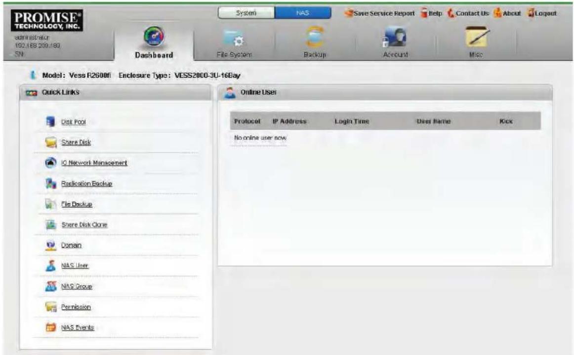
The Dashboard for NAS configuration is organized and functions in much the same way as the System Dashboard, with links to the most frequently accessed menus in the left hand panel, and an information display in the main display panel that lists current NAS users. The primary configuration and NAS function menu tabs are located near the top of the page.
FILE SYSTEM
The main functions of the File System menus are presented in the following sections:
- "Create a Disk Pool" on page 257
- "Create a Share Disk" on page 261
- "Create a NAS portal" on page 270 (I/O Network Management)
• "Disk Pool Transport" on page 265
The sections listed above provide step-by-step descriptions for setting up basic NAS function in the Vess R2000 Series. In addition, the File System menus also used to:
• Extend an existing Disk Pool
• Create a Home Share disk
- Mount an ISO image
- Create user quotas
- Enable/disable NAS protocols
All these functions are covered in the sections that follow.
CREATE A DISK POOL
The first step to setting up the NAS function for the Vess R2000 Series is to create a Disk Pool. A Disk Pool is simply a group of physical hard drives that are dedicated for use in a NAS configuration. The Disk Pool is used for creation of one or more Share Disk(s) that are made available for users for file-based NAS storage. Users with access privilege can access the Share Disk or Disks through the NAS Portal. Follow the procedure below to create a Disk Pool, then proceed to "Create a Share Disk" and "Create a NAS portal" to read instruction for completing the setup procedure for the NAS function.
To create a Disk Pool:
- Click on the NAS Configuration button at the top of the menu to change the user interface to NAS Configuration.
Disk Pool list (no Disk Pools)

- Click on the File System menu tab, then the Disk Pool menu link.
Create Disk Pool main menu (Choose drives for Disk Pool)

- Click on the Create button, the Create Disk Pool menu displays.
- The Create Disk Pool menu displays a virtual front of the Vess R2000 enclosure. Hard disk drives that are unavailable for use appear colored in light blue shading (see example above). Hard disk drives that are available for the Disk Pool appear with the power LED lighted on and without any shading (HDDs 13 - 16 in the above example).
- Choose the hard drives to use for the Disk Pool being created and click the Next button. A new menu appears. Note that selected hard disk drives appear purple color after selection.
- In the new menu, enter a name for the Disk Pool and select a RAID Level from the pull-down menu. The RAID level options available depend on the number of hard disks in the Disk Pool.
- Click on the Apply button to create the new Disk Pool. The newly created Disk Pool appears listed in the main Disk Pool menu. The amount of time needed for initialization of the Disk Pool depends on its capacity.
Create Disk Pool configuration menu


Note
For best performance, a Disk Pool of 4 - 6 hard disk drives with a RAID 5 configuration is recommended. However the Disk Pool can use more hard disk drives or RAID configuration if the user prefers.
Disk Pool appears listed
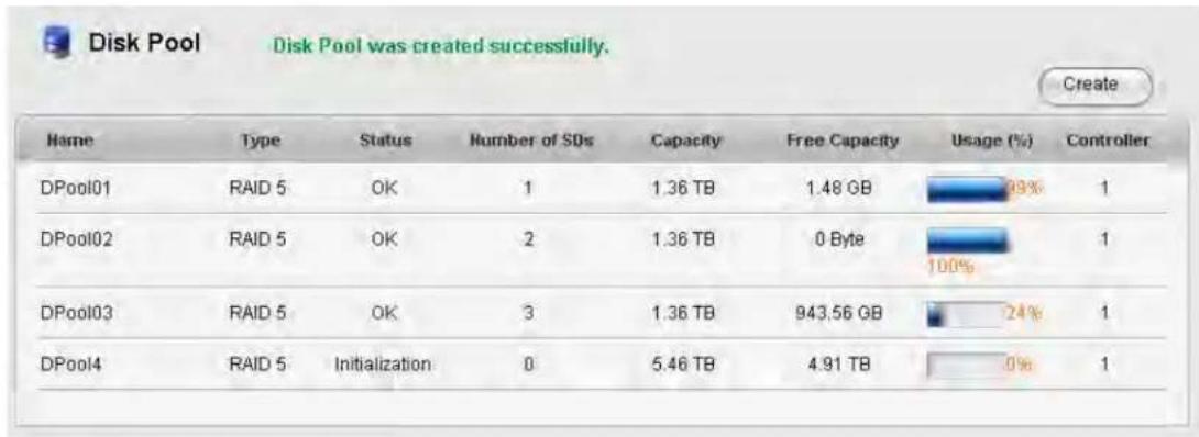
Once the Disk Pool is created, you can create a Share Disk with part of or all the available capacity on the Disk Pool. For step-by-step setup instruction to create a Share Disk, please skip ahead to "Create a Share Disk" on page 261.
It is also possible to extend a Disk Pool after it has been created. For instruction on how to extend a NAS Disk Pool, please see the next section, "Extend a Disk Pool".
EXTEND A DISK POOL
A previously created Disk Pool can be extended if there are physical disks available. A Disk Pool extension must use the same RAID type as the Disk Pool that is being added to. Therefore, the same restrictions apply regarding the minimum number of drives needed for the addition. For example, if you are adding to a RAID 5 Disk Pool, you will need to choose at least four physical drives for the extension.
To add capacity to an existing Disk Pool by creating an extension:
- Move the cursor over the Disk Pool you want to extend in the Disk Pool list, and click on the Extend button.
- Choose available physical disks by clicking on them (similar to the Create Disk Pool menu). The disks chosen change color and appear in the list under the virtual device in the menu (same as with Create Disk Pool menu).
- Click the Apply button to add the selected disks to the Disk Pool.
The the initialization process begins for the added disks.
CREATE A SHARE DISK
After creating one or more Disk Pools, it is time to setup the Share Disks. The Share Disks function like a shared folder or virtual disk. They can be configured to use part or all of the available capacity on a Disk Pool, using one or more of the following protocols: CIFS, NFS, AFP, FTP and WebDAV. Follow the instructions below to create one or more Share Disks.
The Share Disk menu also allows creation of a Home Share (one per Disk Pool), as well as the Mount ISO Image function. These features are described in later sections. Please read "Create Home Share Disk" on page 264 and "Mount ISO image" on page 269 for more information.
To create a Share Disk:
- Create at least one Disk Pool (see "Create a Disk Pool" on page 257).
- Click on the Share Disk menu link. The Share Disk menu appears listing Share Disks that have already been created.
Share Disk menu
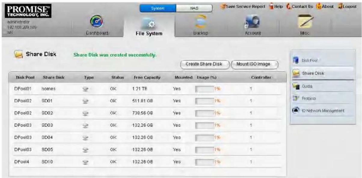
- Click on the Create Share Disk button. A new menu is displayed.
Create Share Disk menu

- Choose the Disk Pool that will be used for the Share Disk from the pull-down menu, enter a name for the Share Disk, enter a value for the Capacity in GB (gigabytes) or TB (terabytes) to use for the Share Disk; or click the option to Use All Available Capacity to use the capacity remaining on the Disk Pool.
- Set the Default Permission for read and write privileges for users of the Share Disk. Note that read and write permissions for any Share Disk can be changed later. To change permission settings for an individual or group, go to the Permission menu under the Account menu tab. To change the permission setting for an entire Share Disk, click on the Share Setting button for the disk you want to change in the Share Disk list.
-
Click to select what protocols will be used for the Share Disk. The available options are Windows (CIFS), Unix/Linux (NFS), Mac (AFP), FTP and WebDAV. Protocols must be universally enabled before they are available for use. By default, they are all enabled. To enable or disable any protocol system-wide for the NAS, use the Protocol menu.
-
You have the option to Enable Encryption for the new Share Disk.
- Click on the Apply button to create the new Share Disk. The newly created Share Disk configuration appears listed in the main Share Disk menu. See example below.
New Share Disk appears in menu

When you have completed creation of the Share Disks, you can then create a portal which includes the IP address used to access the Share Disks on the NAS. Skip ahead to "Create a NAS portal" on page 270 to read a description of how to create a NAS portal.
CREATE HOME SHARE DISK
A single Home Share Disk can be created for the NAS. The Home Share Disk procedure is basically identical to the Create Share Disk procedure described in the previous section.
User folders are available on the Home Share Disk when accessed via CIFS, FTP or AFP.
To create a Home Share Disk, follow these steps:
- Click on the Create Home Share Disk button.
- Choose the Disk Pool that will be used for the Share Disk from the pull-down menu, enter a name for the Share Disk (optional), enter a value for the Capacity in GB (gigabytes) or TB (terabytes) to use for the Share Disk; or click the option to Use All Available Capacity to use the capacity remaining on the Disk Pool.
- Click to select what protocols will be used for the Share Disk. The available options are Windows (CIFS), Mac (AFP), and FTP. Protocols must be universally enabled before they are available for use. By default, they are all enabled. To enable or disable any protocol system-wide for the NAS, use the Protocol menu.
- Click the Apply button to create the Home Share Disk.
Disk Pool Transport
The Vess R2000 supports transport of a Disk Pool. That is, a Disk Pool created on one Vess R2000 enclosure can be removed and installed in another Vess R2000 enclosure, but there is a process that must be completed before the physical drives are removed. This procedure is very similar to the Disk Array Transport described in "Preparing a Disk Array for Transport" on page 196.

Note
Export the NAS settings file to your local computer before transporting, then import and apply the settings in the enclosure that receives the Disk Pool in order to preserve the settings for the Disk Pool.
Before you begin the Transport procedure, first backup (export) the NAS settings so the same settings can be applied to the Disk Pool in the other enclosure. Follow the instructions below.
EXPORT NAS SETTINGS FOR TRANSPORT
To export NAS settings:
- In NAS configuration: Misc and click the Backup/Restore Settings button.
- Select the Export tab and click the Submit button.
- Place the settings .imp file on the local computer.
- Proceed to the Transport procedure.
TRANSPORT DISK POOL
To prepare a Disk Pool for transport, follow these steps:
- In NAS configuration: File System > Disk Pool and click on the Share Disk in the list you want to move.
- Click on the Transport button.
- Click on the Confirm button in the pop-up menu.
A message informs you that the Disk Pool is ready for transport. Now you can safely remove the physical disks and reinsert them into available disk bays on another Vess R2000 enclosure. Once inserted, it will be necessary to Rescan the Disk Pool so it can be used.
RESCAN DISK POOL
After the complete Disk Pool (i.e. all the physical drives of the transported Disk Pool) has been installed on the other Vess R2000 enclosure, it will be detected automatically. In order to begin using it however, one more procedure remains, to Rescan the Disk Pool.
- Go to the Disk Pool list, NAS configuration: File System > Disk Pool.
- Notice there is now a button, Rescan, that appears above the list. Click on the Rescan button. When the Disk Pool has been scanned, a Success message appears. It is now ready for use.
Rescan transported Desk Pool

IMPORT NAS SETTINGS FOR TRANSPORTED DISK POOL
Now that the Disk Pool has been physically installed and rescanned, you can apply the same settings for it from the previous enclosure. To import NAS settings:
- In NAS configuration: Misc and click the Backup/Restore Settings button.
- Click on the Import tab and click Browse to locate the imp settings file.
- Click the Submit button and then the Confirm button. A message appears that the settings have been changed. The Disk Pool should now be functionally the same as it had been in the enclosure it occupied previously.
SET USER QUOTAS
The default settings for users and groups do not place any limit on the amount of disk space available for use. To set a limit on the total amount of disk space allowed for use by a Domain Group, Local Group, Domain User or Local User, use the Quota Setting menu. Quotas are measured in Gigabytes, a value of 0 means there is no quota limit for the user or group.
Quota Setting menu
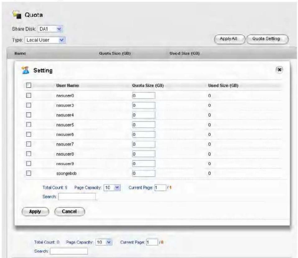
To set a Quota, follow these steps:
- In NAS Configuration, File System > Quota.
- Click on the Quota Setting button.
-
From the pull-down menus in the upper left of the menu, choose the Share Disk and Type (Local User, Local Group, Domain User, Domain Group).
-
Set the Quota for the Group or User, there are two methods for applying the quota:
- Apply Quota for All: To apply the same size quota for all users or for all groups, choose the Type (Local User, Local Group, Domain User, Domain Group) click the Apply All button, type the quota being applied and click the Save button.
- Select Groups or Users for Quotas: To apply quotas for individual users or individual groups, choose the Type (Local User, Local Group, Domain User, Domain Group) click the Quota Setting button, choose the users or groups that will be effected by the quota, type the value for the quota being and click the Apply button.
Quotas can be deleted or changed for any user or group individually for any user or group in the list. Choose the Type (Local User, Local Group, Domain User, Domain Group) to view the list of Users or Groups with the current quota settings. Click on the Setting button for a User or Group in the list that you want to change. Click the Delete button for any User or Group you want to remove the quota limit.
MOUNT ISO IMAGE
NAS configuration enables the use of ISO image files that have been previously placed on a Share Disk, including a Home Share Disk. When the ISO image is mounted, it becomes available for users of the Share Disk.
To mount an ISO image, follow these steps:
- Click on the Mount ISO Image button.
- Choose the Share Disk where the ISO file is located from the Source Share Disk pull-down menu.
- Use the ISO Image File menu to locate the ISO file.
-
Click to select what protocols will be used for the Share Disk. The available options are Windows (CIFS), Unix/Linux (NFS), Mac (AFP), FTP and WebDAV. Protocols must be universally enabled before they are available for use. By default, they are all enabled. To enable or disable any protocol system-wide for the NAS, use the Protocol menu.
-
Click the Apply button to mount the ISO image.
CREATE A NAS PORTAL
The final step to configuration of NAS is to create a NAS portal. In order to better understand the configuration options for port and portal configuration, a few different examples of cabling schemes and the configuration of I/O ports used with the cabling arrangement are presented with illustrations. To create a portal for NAS:
- In NAS Configuration, click on the File System menu tab, then the I/O Network Management menu link. The top menu displayed lists any current Portal configurations including the IP address used for the portal.
- Click on the Create Portal button, a new menu appears.
- Configure the NAS portal. The choices include options to create a port trunk or to use individual ports without trunking, configuration of IP settings, and VLAN settings. Please refer to the examples that follow for explanations of these portal settings.
Create Portal menu
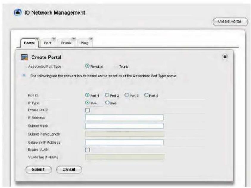
WHAT IS A NAS PORTAL?
A portal is the logical point of connection between the Vess R2000 Series and the NAS clients. Portals use an IP address and a TCP port number to identify an IP storage resource. Normally only one portal is created for NAS, though multiple portals can be used for NAS. Many portals might be used for iSCSI operations.
Vess R2000 Series supports both IPv4 and IPv6 addresses.
Portals on Vess R2000 Series supports the following types of port associations:
- Port ID – The number of the Gigabyte Ethernet data port associated with the portal.
- Controller ID - For dual controller subsystems, the Controller ID and Port ID indicate the physical data port associated with the portal.
- VLAN – Virtual Local Area Network. The portal is part of a virtual network, data frames contain a VLAN tag read by switches and routers to indicate what VLAN it belongs in.
- Trunk – An aggregation of two or more Gigabyte Ethernet ports on the same controller. Also known as a link aggregation. This feature combines ports to increase bandwidth.
CABLING AND PORTAL SETTING FOR NAS AND ISCSI
This section uses illustrated examples to demonstrate some cabling schemes that can be used for NAS and iSCSI operation as well as the corresponding port and portal configuration create using the I/O Network Management menu located in the NAS Configuration menus.
As a reminder, the physical ports for data and management are pictured below with data ports numbered. The tables with the examples used in this section refer to the controllers and physical data ports by number.
Management and Data ports on Vess R2600iD


Important
For dual controller systems, the NAS portal always runs through the Master controller regardless of whether the subsystem is Active-Active or Active-Passive. So the portal setting is made on one controller only.
BASIC NETWORK CABLING AND PORT CONFIGURATION FOR NAS AND ISCSI
The first example shows a basic cabling scheme using a single switch or router for all data and management connections. NAS client hosts access storage through IP network via sharing protocols, while application servers access Vess R2000 storage via iSCSI protocol, portal associations are used to keep them separated. See table and Create Portal settings menu example below.
Basic cabling for NAS/iSCSI operation
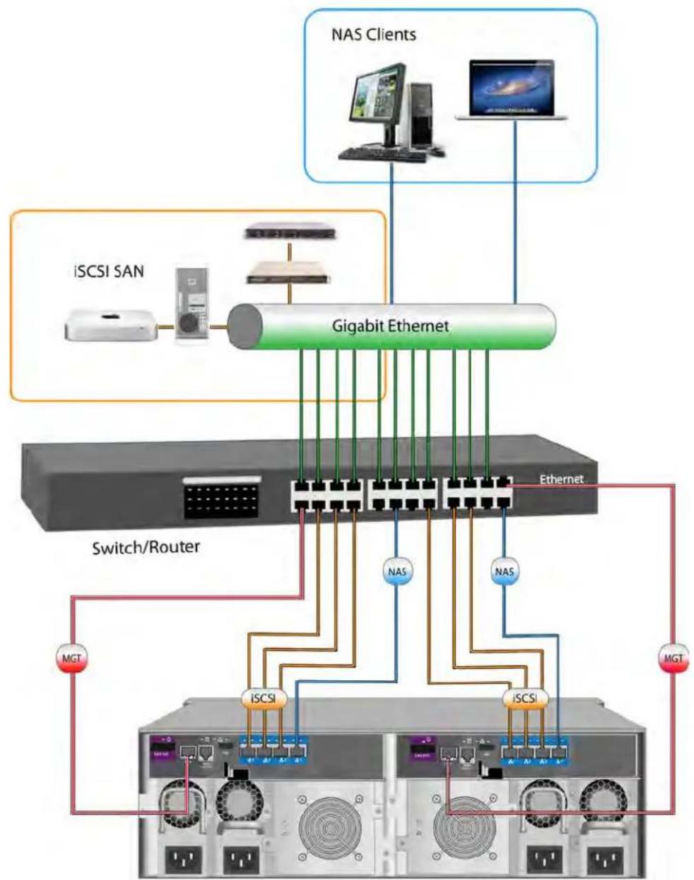
flowchart
graph TD
    A["iSCSI SAN"] --> B["Gigabit Ethernet"]
    C["NAS Clients"] --> D["Computer"]
    C --> E["Computer"]
    B --> F["Switch/Router"]
    B --> G["Ethernet"]
    F --> H["MGT"]
    F --> I["iSCSI"]
    F --> J["iSCSI"]
    G --> K["NAS"]
    G --> L["NAS"]
    G --> M["MGT"]
    style A fill:#f9f,stroke:#333
    style C fill:#f9f,stroke:#333
    style B fill:#ccf,stroke:#333
    style F fill:#cff,stroke:#333
    style G fill:#ffc,stroke:#333
    style H fill:#fff,stroke:#333
    style I fill:#fff,stroke:#333
    style J fill:#fff,stroke:#333
    style K fill:#fff,stroke:#333
    style L fill:#fff,stroke:#333
Table 1: Basic portal associations
| Controller ID 1 | 2 | |||||||
| Port ID 1 2 | 34 1 2 | 34 | ||||||
| iSCSI Portal ID 1 | 2 3X5 | 6 7 | X | |||||
| NAS Portal ID | X | X | X | 16 | X | X | X | If failover = NAS Portal ID 16 |
Create Portal menu
![IO Network Management Portal Port Trunk Ping Create Portal Associated Port Type Physical Trunk The following are the relevant inputs based on the selection of the Associated Port Type above. Port ID Port 1 Port 2 Port 3 Port 4 IP Type IPv4 IPv5 Enable DHCP IP Address Subnet Mask Subnet Prefix Length Gateway IP Address Enable VLAN VLAN Tag [1-4094] Submit Cancel](/content/2026/05/1128996/images/0e3f0f486de9a75e5fe80edad83695cd31bdeae5a793a5c792a7023fab56c55a.jpg)
REDUNDANT PORT CONFIGURATION FOR NAS AND ISCSI
Use of redundancy will prevent disconnection in the event of a port failure on a controller or cable failure. For dual controller subsystems, the iSCSI protocol already has Multipath I/O for redundancy and load balancing. However for NAS it is necessary to create a port trunk to achieve this. Further redundancy is created with more advanced cabling and two switches or routers, and with redundant IP settings.
The first method of redundancy using a single switch or router, uses that same basic cabling arrangement as illustrated in the previous example except that two ports on each controller are trunked and assigned a NAS portal. This example is explained in "Table 2: Redundant portal settings" below and illustrated in "Redundancy with port configuration".
Table 2: Redundant portal settings
| Controller ID 1 | 2 | |||||||
| Port ID 1 2 | 34 1 2 34 | |||||||
| Trunk 1 2 | Trunk 1 1 2 Trunk 1 | |||||||
| iSCSI Portal ID | 1 2 X34 X | |||||||
| NAS Portal ID | X | X | 16 | X | X | If failover = NAS Portal ID 16 | ||

Note
The I/O Network Management and iSCSI Management menus for SAN configuration used to configure redundancies for multiple iSCSI target and ports.
Redundancy with port configuration

flowchart
graph TD
    A["ISCSI SAN"] --> B["Gigabit Ethernet"]
    C["NAS Clients"] --> D["Computer"]
    C --> E["Computer"]
    B --> F["Switch/Router"]
    B --> G["Switch/Router"]
    B --> H["Switch/Router"]
    B --> I["Switch/Router"]
    B --> J["Switch/Router"]
    B --> K["Switch/Router"]
    B --> L["Switch/Router"]
    B --> M["MGT"]
    B --> N["iSCSI"]
    B --> O["iSCSI"]
    B --> P["Trunk Ctrl 1 P3-P4"]
    B --> Q["Trunk Ctrl 2 P3-P4"]
    B --> R["NAS"]
    B --> S["NAS"]
    B --> T["NAS"]
    style A fill:#f9f,stroke:#333
    style C fill:#f9f,stroke:#333
    style B fill:#ccf,stroke:#333
    style D fill:#ccf,stroke:#333
    style E fill:#ccf,stroke:#333
    style F fill:#dfd,stroke:#333
    style G fill:#dfd,stroke:#333
    style H fill:#dfd,stroke:#333
    style I fill:#dfd,stroke:#333
    style J fill:#dfd,stroke:#333
    style K fill:#dfd,stroke:#333
    style L fill:#dfd,stroke:#333
    style M fill:#dfd,stroke:#333
    style N fill:#dfd,stroke:#333
    style O fill:#dfd,stroke:#333
    style P fill:#dfd,stroke:#333
    style Q fill:#dfd,stroke:#333
    style R fill:#dfd,stroke:#333
Thee IP settings in the above example are configured for added iSCSI redundancy. The IP address for NAS however remains the same since NAS is configured for one controller only. It is irrelevant for NAS if the controllers are Active-Active or Active-Standby.
Table 3: Redundant portal IP settings
| Type Controller | Port | Portal | IP Address | Host connects to: | |
| iSCSI Target(Active-Active Mode) | 1 1 1 | 192.168 | 1.50 Mult | path I/O | 192.168.1.50~53 |
| 1 2 2 | 192.168 | 1.51 | |||
| 2 1 31 | 192.168 | 1.52 | |||
| 2 2 4 | 192.168 | 1.53 | |||
| iSCSI Target(Active-Standby Mode) | 1 1 1 | 192.168 | 1.50 Mult | path I/O | 192.168.1.50~51 |
| 2 2 2 | 192.168 | 1.51 | |||
| NAS1 3&4 | Trunk | 16 | 192.168.1.60 | 192.168.1.60 | |
ADVANCED REDUNDANCY NETWORK CABLING AND PORT CONFIGURATION
The final example uses two switches or routers to create an additional layer of redundancy for high availability. Using this cabling method, it is necessary to trunk all four ports on each controller.
Table 4: Advanced redundant portal settings
| Connect to | Switch 1 | Switch 2 | Switch 1 | Switch 2 | ||||
| Controller | 1 | 2 | ||||||
| Port | 1 | 2 | 3 | 4 | 5 | 6 | 7 | 8 |
| Trunk | Trunk 1 | Trunk 1 | ||||||
| iSCSI portal | 1 | 2 | ||||||
| NAS portal | 16 | If failover, NAS Portal ID is 16 | ||||||
Advanced redundant cabling for NAS and iSCSI using two switches

flowchart
graph TD
    A["iSCSI SAN"] --> B["Gigabit Ethernet"]
    C["NAS Clients"] --> B
    B --> D["Switch/Router #1"]
    B --> E["Switch/Router #2"]
    D --> F["Trunk"]
    E --> G["Trunk"]
    F --> H["MGT"]
    G --> I["MGT"]
    J["Mac"] --> K["Computer"]
    L["Computer"] --> M["Monitor"]
Table 5: Advanced redundant portal IP settings
| Type Controller Port Portal IP Address Host connects to: | |||||
| iSCSI Target(Active-Active Mode) | 1 1~4 | P1 192. | 168.1.50 | Multipath I/O | 192.168.1.50~53 |
| 2 1~4 | P2 192. | 168.1.51 | |||
| iSCSI Target(Active-Standby Mode) | 1 1~4 | P1 192. | 168.1.50 | Multipath I/O | 192.168.1.50~51 |
| NAS1 1~4 | N16 192.16 | 8.1.60 | 192.168.1.60 | ||
BACKUP
Backup settings for the NAS are created and configured using the menus described below. Typically the backup relationship is with another Vess R2000 remotely located and managed using these same menus.
• Backup Server Settings
- Replication Backup
- Replication Recovery
- File Backup/Restore
- Share Disk Clone
BACKUP SERVER SETTINGS
The Backup Server Settings is used to designate remote systems that are allowed to backup on the Vess R2000, and configure port settings for the backup via normal or encryption ports. Once the remote IP address is allowed, the remote system, another Vess R2000 for example, can be configured for scheduled backups to this Vess R2000. On the remote Vess R2000, you would use the Replication Backup menu to configure this backup arrangement.
ALLOW IP FOR BACKUP
To add a remote system allowed to backup to the Vess R2000, follow these steps:
- In NAS configuration: Backup > Backup Server Settings
- Click the Create button.
- Type the IP address of the remote system allowed to backup and click the Add button.
- For each system you want to add to the Allow IP list, repeat steps 2 and 3.
- Click the Apply button to create the backup settings.
After the Allow IP list is created for a Share Disk, you can add or remove an IP address allowed for any Share Disk on the list, or remove the Share Disk configuration and all the IP addresses on the associated Allow IP list.
- To add a new IP address to the Allow IP list for a Share Disk backup configuration, click on the Share Disk row in the list, click on the Setting button, for each IP address you want to add, type in the IP address in the space provided and click the Add button. When finished adding IP addresses to the Allow IP list, click on the Apply button.
- To remove an individual IP address from a Share Disk Allow IP list, click on the Share Disk row in the list, click on the Setting button, and the click on the trash can icon for the IP address you want to remove.
- To remove an entire Share Disk backup configuration and all the IP addresses on the Allow IP list, click on the Delete button for the Share Disk backup configuration, then click on the Confirm button that pops up.
BACKUP SERVER PORT SETTINGS
The administrator has the option of using the default port for backup, or specifying the port. The port has an additional option of using encryption for the backup transmissions. Encryption is enabled on the client using the Replication Backup menu (see "Replication Backup" on page 281). Use this menu only if you want to change the default port setting used for backup. Keep in mind that the port change must also be made on the client using the Replication Backup menu.
To change the backup port used for normal or encryption backups:
- In NAS Configuration: Backup > Backup Server Settings
- Click the Port Settings button.
- Click on the Use Default option box to deselect it.
- Type a number in the range 1025 to 65532 for the Encryption Port, and type a different number in the same range for the Normal Port.
- Click the Apply button to change the backup port settings.
REPLICATION BACKUP
Replication refers to the process of copying or mirroring data content on a Share Disk. The Share Disk is recreated entirely on a different NAS. The identical Share Disk uses the same name as well. The policy used to create the replicated Share Disk can be to mirror or copy the Share Disk (see Policy in instructions below).
Keep in mind the following points for a Replication Backup setting.
- Replication Backup Share Disks are made to a remote NAS and must use the same name as the original Share Disk on the source NAS.
- A NAS portal must be configured to create the replicated Share Disk.
- The remote NAS must “allow” the IP address of the Share Disk on the original NAS. See “Allow IP for backup” on page 279.
- Replication Backup policy choices are: Mirror Mode to sync added and changed files, and file deletions are mirrored as well; or Copy Mode to sync added and changed files without deletion of files that were deleted from the source Share Disk.
- Replication Backup can be used for multiple Share Disks on the remote NAS.
- A temporary Share Disk snapshot is created if snapshot is available.
• Differential and compression transmission are supported. - Encryption is supported for transmission.
- Replication Backups can be scheduled.
- Other Replication Backup parameters include connection timeout limit, retry attempts allowed and maximum transfer rate.
Create Replication Backup menu

To create a Replication Backup for a Share Disk, follow these steps:
- In NAS configuration: Backup > Replication Backup
-
Click the Create button, enter configuration settings for the Replication.
-
Enter the IP address of the Remote Backup Server (a separate NAS)
- Choose a Policy for replication: Mirror Mode syncs added and modified files and mirrors file deletion, Copy Mode syncs added and modified files and does NOT delete any files that were deleted on the source Share Disk.
- Optional settings include Encryption (check box to enable) changing the Port on the backup server. To change the default Port number, uncheck the box and type in the port number to use.
- Choose the Portal IP for the NAS from the drop-down menu.
- Choose the Schedule type to use for syncing. Note that the default value Disable means the replication is done manually (see "Run Replication Backup" below).
- Choose the number of Retry Times, the number of times to try again if the connection fails.
- Connection Timeout is the time in seconds allowed for the connection to be idle before disconnecting.
-
Change the Maximum Transfer Rate if you want to limit the rate at which the transfer is allowed to proceed. By default, this is unlimited.
-
Click the Next button to proceed.
The connection will first be validated.
- If the connection to the server is made, choose Share Disks with identical names on both ends of the backup connection, that is, the source and destination Share Disk must have the same name.
- Click the Apply button to create the Replication Backup settings.
RUN REPLICATION BACKUP
To manually run a Replication Backup, follow these steps:
- In NAS configuration: Backup > Replication Backup and click on the Replication Backup setting in the list for the Share Disk you want to backup.
- Click on the Run button.
- You need to confirm to run the backup. Type "confirm" and click on the Confirm button.
REMOVE A REPLICATION BACKUP
To delete a Replication Backup setting, follow these steps:
- In NAS configuration: Backup > Replication Backup and click on the Replication Backup setting to be removed.
- Click on the Delete button.
- You need to confirm to remove the backup. Type "confirm" and click on the Confirm button and the Replication Backup setting is removed.
REPLICATION RECOVERY
After a Replication Backup of a Share Disk is completed on a remote NAS, the backup is available for future recovery. During the recovery, the remote replicated Share Disk is mounted in the same position as the original local Share Disk. When the recovery is completed, the recovered original Share Disk automatically goes back into the normal position and the replication backup Share Disk reverts to backup status.
Keep in mind the following points for Replication Recovery:
- Replication Recovery requires at least one previously replicated Share Disk to replace the local Share Disk. See "Replication Backup" on page 281.
• The remote replicated Share Disk is mounted in the same position the damaged Share Disk occupied.
• Each Share Disk recovery can occur from one replicated Share Disk at a time, even if more than one replicated Share Disks have been created. - When the recovery process is completed, services are automatically switched back to the newly recovered Share Disk which is mounted in the original position.
- During the recovery process, NAS functionality is normal since the remote Share Disk is temporarily active for local NAS users. Service to users of the Share Disk are not affected.
• Differential and compression transmission are supported.
• Whole Share Disk files are synchronized before the switch back to the recovered Share Disk occurs. - Automatic switch back function will delay for up to 24 hours if the Share Disk is busy. After 24 hours if the switch back has not occurred, it will be forced.
To begin the recovery process:
- In NAS configuration: Backup > Replication Recovery and click on the listed Replication Recovery configuration for the Share Disk that has been previously backed up using Replication Backup.
- Click on the Recover button.
- Choose the backup server, and click the Apply button.
FILE BACKUP/RESTORE
The File Backup and Recovery function is similar to the Share Disk Replication Backup and Recovery, except instead of backing up the entire contents of a Share Disk, you choose individual files to backup. Also there is an additional policy mode Version which syncs all file changes in a new folder, effectively saving a new time-stamped version of the file. The Version policy allows restoration of backed up versions of files, selected according to the time created.
Keep in mind the following points for File Backup and Restore:
For File Backup:
• The destination Share Disk can be located on a remote NAS or on the local one.
- Files for backup must all be on the same Share Disk.
- Setup a NAS portal configuration before using File Backup.
- For backup to a remote NAS, the remote NAS must "allow" the IP address of the Share Disk on the original NAS. See "Allow IP for backup" on page 279.
• A temporary Share Disk snapshot is created if snapshot is available.
- A folder on the destination Share Disk named Backup is created for the backed up files.
- Hard link is used for reserving the destination Share Disk space if there are multiple copies.
- Differential and compression transmission is supported.
• File Backups can be scheduled.
- Other File Backup parameters include retry attempts allowed.
For File Restore:
- File Restore settings are dependent upon the file backup task.
- If the destination backup Share Disk is on a remote site, the remote NAS must "allow" the local IP. See "Allow IP for backup" on page 279.
- All restored files on the original Share Disk are placed in a file named Restore, the task name and date version are included in the file path.
- Differential and compression transmission is supported.
To configure File Backup:
- In NAS configuration: Backup > File Backup/Restore and click on the Create button.
Configure these settings:
- Task Name: Enter a task name for the File Backup configuration.
• Source Share Disk: Select the source Share Disk from the drop-down menu - Direction: Select From Local To Local or From Local To Remote from drop-down menu depending on whether the backup is to a local or remote Share Disk.
If remote Share Disk is the destination, enter the IP address of the Remote Backup Server where the backup Share Disk is located and the Portal IP used.
- Destination Share Disk: Select the destination Share Disk from the drop-down menu.
• Policy: Select the backup policy to use.
Mirror Mode: Synchronize all added, modified and deleted files
Copy Mode: Only syncs files that are added and modified files, without syncing deleted files
Version Mode: Creates a new folder for syncing all files.
-
Choose the Schedule to use for syncing the File Backup. Note that the default value Disable means the Backup is done manually (see below).
-
Choose the number of Retry Times, the number of times to try again if the connection fails.
-
Click on the Next button.
-
Choose which files to backup.
-
Click the Save button to create the File Backup configuration.
RUN FILE BACKUP
To manually run a File Restore, follow these steps:
- In NAS configuration: Backup > File Backup/Restore and click on the File Backup setting in the list for the Files you want to backup.
- Click on the Run button.
- Click on the Confirm button in the pop-up menu.
The time needed to restore the files depends on the size of the files being restored.
RESTORE FILE BACKUP
- In NAS configuration: Backup > File Backup/Restore and click on the File Backup setting in the list for the Files you want to restore.
- Click on the Restore button.
- For Mirror Mode or Copy Mode File Backup, click on the Confirm button in the pop-up menu.
- For Version Mode File Backup, choose the restore version from the list and click on the Apply button.
REMOVE FILE BACKUP
To delete a File Backup configuration:
- In NAS configuration: Backup > File Backup/Restore and click on the File Backup setting in the list.
- Click the Delete button.
- Click on the Confirm button in the pop-up menu.
SHARE DISK CLONE
The Share Disk Clone duplicates data on a Share Disk to another Share Disk located on a different Disk Pool.
Keep in mind the following points for Share Disk Clone:
• Source and destination Share Disks must be located in different Disk Pools.
- Share Disk Clone can be scheduled.
- The permission of the destination Share Disk is "Read Only"
To setup a Share Disk Clone:
- In NAS configuration: Backup > Share Disk Clone click on the Create button.
Configure settings:
- Source Share Disk: Select the source Share Disk from the drop-down menu
- Destination Share Disk: Select the destination Share Disk from the dropdown menu, must be different from the source Share Disk.
• Policy: Select a clone policy:
Mirror Mode: Synchronize all added, modified and deleted files
Copy Mode: Only syncs files that are added and modified files, without syncing deleted files
- Choose the Schedule to use for syncing the File Backup. Note that the default value Disable means the Share Disk Clone must be run manually.
- Choose the number of Retry Times, the number of times to try again if the connection fails.
RUN SHARE DISK CLONE
To manually run Share Disk Clone, follow these steps:
- In NAS configuration: Backup > Share Disk Clone and click on the Share Disk Clone button to run.
- Click on the Run button.
- Click on the Confirm button in the pop-up menu.
REMOVE FILE BACKUP
To delete a File Backup configuration:
- In NAS configuration: Backup > Share Disk Clone and click on the Share Disk Clone to remove.
- Click the Delete button.
- Click on the Confirm button in the pop-up menu.
ACCOUNT MANAGEMENT
Management of NAS local and domain users and user groups, user permission settings and the Domain setting are done in the menus under the Account tab. NAS users can simultaneous be both local and domain users and be in multiple user groups.
The Type pull-down menu toggles the menu between Local User and Domain User menus. To navigate the pages, click on the arrow symbols near the bottom of the menus to change the display, previous page, next page, first and last page. Use Page Capacity to determine how many rows of user or group information are displayed on the page. The Search function is used to locate a user by name. To search a name, type the name in the entry field and press Enter.
In NAS configuration: Account > NAS User and choose Local User from the Type pull-down menu. Use the list of current local users to view basic information, change the user password, change user settings or to delete the user. For each of the local user actions listed here, first locate the Local User in the list (use the navigation tools described in "Query Local and Domain Users") and move the cursor to the list row for the user, and click on the appropriate button to perform the action or display information.
To View Local User Information
Click on the View button to display basic user information.
- Click Change Password button
- Type the new password in the Password and again in the Retype Password entry fields.
- Click the Apply button.
To input Local User Information
- Click the Setting button
- Fill in Description and Email fields
- Click the Apply button.
To remove a Local User
- Click the Delete button.
- Click the Confirm button.
Add Local Users
Local users can be added individually or many users can be added at once. For multiple users, an index number is added to the user name for the quantity of users being added.
TO ADD A SINGLE LOCAL USER FOR THE NAS
- Click Account tab > NAS User.
- Choose Local User from the Type pull-down menu.
- Click the Add User button.
In the Add User menu, enter the required settings:
- User Name
- Password
- Retype Password
- Description
-
Email
-
Click the Apply button to apply and save the settings.
The newly created user appears listed in the Local User list.
TO ADD A MULTIPLE LOCAL USERS FOR THE NAS
- Click Account tab > NAS User.
- Choose Local User from the Type pull-down menu.
- Click the Add Multiple Users button.
In the Add Multiple Users menu, enter the required settings:
- Start Index
• Quantity - User Name (the prefix of the user name that is followed by the index value)
- Password
- Retype Password
To remove Multiple Users from the Local Users List
- Click Account tab > NAS User.
- Choose Local User from the Type pull-down menu.
- Click the Delete Multiple Users button.
- Click to select the check box for each user you want to delete. Use paging feature if necessary.
- Click the Apply button.
To Import Users to the Local Users List
- Click Account tab > NAS User.
- Choose Local User from the Type pull-down menu.
- Click the Import Users button.
- Select the CSV format file containing user information you want to import.
- Check if you want overwrite user data if there exists the same user name in system.
- Click the Submit button.
NAS GROUP SETTINGS
Use the NAS Group menus for setting both Local and Domain User groups.
In the Account tab, click the NAS Group button and use the Type pull-down menu toggles the menu between Local Group and Domain Group menus. To navigate the pages, click on the arrow symbols near the bottom of the menus to change the display, previous page, next page, first and last page. Use Page Capacity to determine how many rows of user or group information are displayed on the page. The Search function is used to locate a group by name. To search a name, type the name in the entry field and press Enter.
USING THE NAS GROUP LIST
In NAS configuration: Account > NAS Group. Use the list of current groups to view members information, change groups settings or to delete the group.
To View Group Members
- Move the cursor to the row of the group in the list.
- Click the View button.
Add Local Group and Choose Local User MEMBERS
- Use the Type pull-down menu toggles the menu between Local Group.
- Click the New Group Create button.
- Enter a Group Name and click the boxes to select member local users from the list.
- Click the Apply button to create the local user group.
- Use the Type pull-down menu toggles the menu between Local Group.
- Click the Settings button.
- Add or remove local users by selecting or deselecting the selection boxes for the users in the list.
- Click the Apply button.
- Use the Type pull-down menu toggles the menu between Local Group.
- Click the Delete button.
- Click the Confirm button.
Use the Domain menu to create a Domain Workgroup or to join a Domain on the network using Windows Active Directory or LDAP.
To Join a Domain
- In NAS configuration: Account > Domain then click the Join Domain button.
- Choose the Domain Type and configure settings accordingly.
• Active Directory
i. Enter the Active Directory domain and domain DNS server (server IP), the NetBIOS name is set automatically.
ii. Click the Next button.
iii. Select one domain controller.
iv. Enter the Administrator Account and Password.
v. Click the Apply button to join the domain.
- LDAP
i. Enter the LDAP Server Host
ii. Choose the LDAP Security
iii. Enter the Base DN, Root DN and Password.
iv. Click the Next button.
v. Select one domain name.
vi. Click the Apply button to join the domain.
To Leave a Domain
In NAS configuration: Account > Domain then click the Leave Domain button.
To Set a Workgroup
- In NAS configuration: Account > Domain.
- Enter a Workgroup Name.
- Click the Apply button.
To Refresh Domain Data
- In NAS configuration: Account > Domain.
- Click the Refresh Domain Data button.
PERMISSION SETTING
Set user and user group permissions and set default permission for a Share Disk. If there are conflicts among permission settings, the rule to settle conflicts is as follows: Deny > Read/Write > Read Only (in Windows(CIFS), Mac(AFP), FTP) and Read/Write > Read Only > Deny(in WebDAV).
To Display Permission Settings
- In NAS configuration: Account > Permission.
- Choose the Share Disk and Type (Local User, Local Group, Domain User, Domain Group) to display permission settings.
To Set Default Permission for Share Disk
- In NAS configuration: Account > Permission.
- Choose the Share Disk to set permission settings.
- Click the Default Permission Setting button.
- Click to select a radio button for Read-Write, Read-Only or Deny-Access setting.
- Click the Save button.
To Set Permission for Users or Groups
- In NAS configuration: Account > Permission.
- Choose the Share Disk and Type (Local User, Local Group, Domain User, Domain Group) to set permission settings.
- Click the Permission Setting button.
- Click to check mark the selection boxes for the Users or Groups for which the permission settings apply.
- Click to select a radio button for Read-Write, Read-Only or Deny-Access setting.
- Click the Save button.
MISCELLANEOUS
Miscellaneous menus include:
- Backup/Restore Settings
- Reset NAS Settings
- NAS Events
BACKUP/RESTORE SETTINGS
Use the Backup/Restore Settings menu to to import or export NAS settings.
- In NAS configuration: Misc and click the Backup/Restore Settings button.
- Choose to Export or Import settings.
- To Export, select the Export tab and click the Submit button.
- To Import, click the Import tab, click Browse to select a location to place the file, then click the Submit button.

Note
Use the Export and Import settings function when you transport a Disk Pool. See "Disk Pool Transport" on page 265 for details.
RESET NAS SETTINGS
Use this to restore the factory preset values. You can choose which NAS settings to revert to default settings.
To set NAS settings to their factory default values:
- In NAS configuration: Misc and click the Reset NAS Settings button.
- Click to choose the NAS Default Settings from list that you want to change back to default. Clicking on the box at the top of the list selects all settings categories in the list.
- Click the Apply button.
NAS EVENTS
The NAS Events log displays error, warning, and information messages involving the NAS.
To display the NAS Events log:
- In NAS configuration: Misc and click the NAS Events button.
- Use the log menu to query event types to display. The options are to show Warning and Error or All NAS Events.
Use the navigation arrows and page display options to view the log according to your preference.
Clear/Save NAS Events log
Other log functions include clearing or saving log entries.
To clear all NAS Event log entries, click the Clear Log button. A pop-up menu appears asking to confirm, type "confirm" and click the Confirm button.
To save the log, click the Save button.
MANAGING WITH THE CLI
MAKING A SERIAL CONNECTION
Before you begin, be sure the RJ11-to-DB9 serial data cable is connected between the Host PC and the Vess enclosure, and that both machines are booted and running.
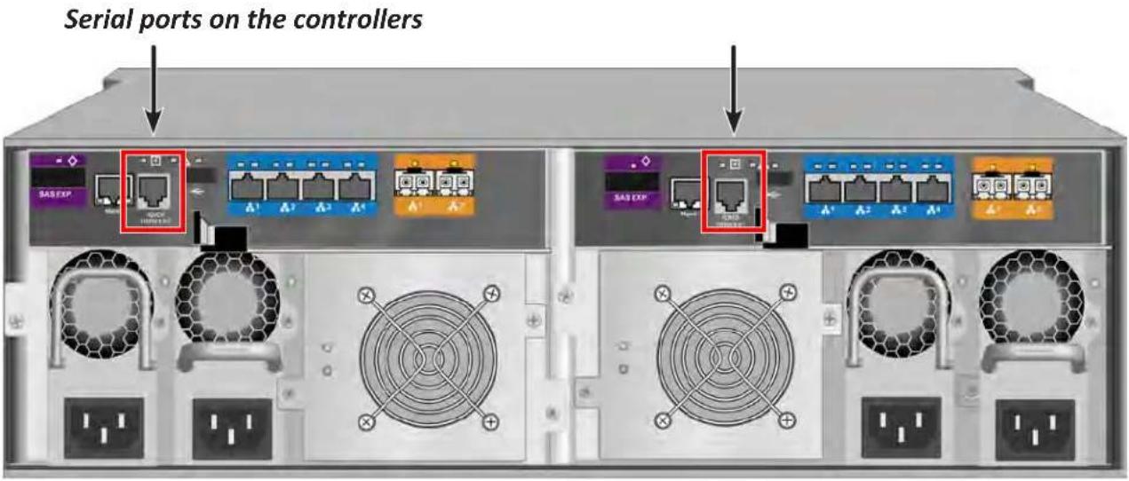
Then do the following actions:
-
Change your terminal emulation program settings to match the following specifications:
-
Bits per second: 115200
- Data bits: 8
- Parity: None
- Stop bits: 1
-
Flow control: none
-
Start your PC's terminal VT100 or ANSI emulation program.
- Press Enter once to launch the CLI.
LOGGING INTO THE CLI
- At the Login prompt, type the user name and press Enter.
The default user name is administrator.
- At the Password prompt, type the password and press Enter.
The default password is password.
The CLI screen appears.
CLI administrator prompt

TABLE OF SUPPORTED COMMANDS
The table below and on the following pages provides a brief description of the CLI commands available on the Vess R2000 Series.
| CommandAction | |
| menu | Use to switch interface to CLU. |
| help | When used alone will display this menu. When used in conjunction with a command (example: help array) it will display help information for that particular command. |
| ? | This can be used in place of the help command or optionally can be used as a switch for a command (example: array -?) to provide command usage. |
| about | View utility information. |
| array | View or edit array information. Create, edit, or delete logical drives in an existing array. To physically locate an array in an enclosure. Accept an incomplete array condition. |
| assn | View, create, or delete associations between logical drives. |
| battery | View battery information or to recondition a battery. |
| bbm | View or clear the BBM defect list of the specified configured physical drive. |
| bga | View status of all current background activities. Enable or disable relevant background activities. Modify the background task rate for each of the background tasks. |
| bgasched | View, add, modify or delete bga scheduled background activities. |
| buzz | View buzzer status, enable/disable and turn on/off buzzer. |
| checktable | View logical drive error tables. |
| chap | Add, modify or delete a CHAP record for authentication of iSCSI host interface. |
| clone | View logical drive clone status and progress. Start, stop a clone. |
| config | For express or automatic configuration.For advanced configuration please see the ‘array’ command. |
| ctrl | View or edit controller information and settings. |
| Note: Commands are NOT case sensitive. | |
| date | View or edit system time. |
| enclosure | View or edit enclosure and SEP information and settings. Locate an enclosure via LEDs. |
| event | View or clear events logs. |
| export | Subsystems only. Export files to remote TFTP host. |
| factorydefaults | Restore settings to factory defaults. |
| fc | View or edit fc information and settings. Fibre Channel host interface product only. |
| import | Import files or license from remote TFTP host |
| init | View logical drive initialization status and progress. Start, stop, pause, or resume an initialization or a quick initialization. |
| initiator | View initiator list, add or delete initiator entry. |
| iscsi | View or modify iSCSI settings. For iSCSI host interface only. |
| isns | View or modify iSNS settings. For iSCSI host interface only. |
| Note: Commands are NOT case sensitive. | |
| lunmap | View the LUN mapping and masking table. Enable or disable LUN mapping and masking on Fibre Channel host interface product. Add, delete or modify an LMM entry. |
| logdrv | View or edit logical drive information and settings. Locate a logical drive via LEDs. |
| logout | Logout session for the current user. |
| maintenance | Enter or exit maintenance mode. |
| migrate | Start and monitor disk array migration process. |
| mp | View media patrol status and progress. Start, stop, pause, or resume media patrol. |
| net | View or edit Ethernet network information and settings. |
| ntp | View or edit NTP status and settings. |
| password | Modify a user's password. |
| pdm | View PDM status and progress. Start, stop, pause, or resume PDM process. |
| perfstats | Start and view performance statistics for controllers, logical drives, physical drives or ports. |
| phydrv | View or edit physical drive information and settings. Locate a physical drive via LEDs. |
| ping | Ping another system through management port. |
| ptiflash | Update system software and firmware through tftp server. |
| rc | View redundancy check status and progress. Start, stop, pause or resume redundancy check. |
| rb | View rebuild status and progress. Start, stop, pause, or resume a rebuild process. |
| Note: Commands are NOT case sensitive. | |
| Command | Action |
| sasdiag | SAS diagnostic command. |
| sas | View or edit SAS host interface port information and settings. SAS host interface product only. |
| sc | View spare check status. Start spare check. |
| scsi | View or edit parallel SCSI information and settings. Parallel SCSI host interface product only. |
| session | View the list of active sessions. |
| shutdown | Shutdown or restart system. |
| smart | M.A.R.T diagnostic for physical drives. |
| spare | Create or modify hot spare drives. |
| stats | View or reset statistics. |
| subscription | View, modify, enable or disable event notification. |
| subsys | View or edit subsystem information and settings. |
| swmgt | View, start or stop software component. |
| sync | View logical drive synchronization status and progress. |
| topology | View SAS topology, the physical connections and device information. For products that support multiple enclosures only. |
| transit | View transition status and progress. Start, stop, pause, or resume a transition process. |
| trunk | View, modify, add or delete port trunk configuration for iSCSI host interface. |
| ups | View or modify UPS information and status. |
| user | List, modify, create and delete user accounts on subsystem. |
| zoning | List, modify SAS zoning on subsystem. |
| Note: Commands are NOT case sensitive. | |
NOTES AND CONVENTIONS
Commands and options are NOT case sensitive.
Not all extended keys are supported. However, you can use the backspace and the left and right arrow keys for command line editing. In addition, the up and down arrow keys allow scrolling through the command history buffer.
If you need context-sensitive help, type one of the following commands:
-h -? - help
That action will display full context-sensitive help for the specific command. Each command when used alone, such as “array” will display a summary of relevant information. If more information is desired, the -v verbose mode can be used. This will provide information for all relevant aspects of that command.
Usage terminology is as follows:
• [square braces] depict an optional switch
-
Type “ | more” at the end of each command, to display info page by page
about
Usage
about
Summary
Displays utility information.
array
Usage
array [-a <action>] [-d <Dald>] [-c <array count>] [-v]
array -a add [-s "<list of array params>"] [-d <Dald>] -p <Pdld list>
[-c <Ld count>] [-I "<list of Ld params>"]
array -a mod -d <Dald> -s "<list of array settings>"
array -a del -d <Dald list>
array -a locate -d <Dald>
array -a accept -d <Dald> [-t <condition type>]
array -a addId -d <Dald> [-c <Ld count>] -l "<list of Id settings>"
array -a dellId -l <Ldld list>
array -a transport -d <Dald>
Summary
The array command is the main command for performing advanced configuration and maintenance tasks on disk arrays.
This command is used to list, create, modify, delete, and locate disk arrays. Also to add and delete logical drives.
Note that you cannot mix Hard Disk Drives (HDD) and Solid State Drives (SSD) in the same disk array.
Options
-a
list (Default) Displays a summary of all or a specific or a specified
number of arrays.
add Add/create an array and possibly some logical drives
at the same time.
addId Add/create a logical drive to an array that already
exists.
delld Delete an existing logical drive from an array.
mod Modify settings of an existing array.
del Delete an existing array and all its associated logical drives.
locate Locate an array.
accept Accepts the condition of an incomplete array. There are two
conditions that will cause the array to report as incomplete:
- Missing Drive, i.e. when one or more drives are missing in the array.
- Missing NVRAM Watermark, the NVRAM Watermark of migration
not found on the controller, however the DDF on the array
indicates the migration is in progress.
When the either of the above condition happens, all the logical drives on the
array will become offline.
The user can do an accept to acknowledge the incomplete condition of the array, and try to recover the access to the array and logical drives on the array, in other words, to bring the logical drives online. However, it is a high-risk and non-revertible operation, and it may result in data loss.
Therefore, it is recommended to try to clear the condition first, e.g., to put the missing drives back; or to roam the array back to the original controller and wait until the migration completes.
transport To gracefully make the array and the logical drives on the array
offline to get ready for transport the array to another subsystem.
untransport Cancels the transport action on the array and the logical drives.
Brings the array back online in the original subsystem.
Not supported for HBA products.
online To set all the dead physical drives of array online at a time.
-d
desired array ID when creating (add) an array.
Used to specify the array ID when listing array information
modifying, deleting, locating, accepting, adding or deleting a
logical drive. Only one array may be specified.
-p
Used in conjunction with -a add. PD IDs can be used singly or
separated by comma. Additionally a sequential group of physical
drives can be specified by placing a \~ between numbers such as
1\~6. This will include physical drives 1,2,3,4,5,6.
-s "
(add) or modifying (mod) an array. These options are comma
separated.
alias= A user specified name used to identify an array. It can be up to 32
characters long, containing alpha-numeric characters, blank
spaces and underscores.
The beginning and ending blank spaces will be discarded.
mediapatrol= Used to enable or disable media patrol for this array.
enable The default is enable.
disable
powermanagement= Apply controller power management setting.
enable (Default) Controller power management setting will be
applied to this disk array.
disable Controller power management setting will not be applied to this
disk array.
pdm= Used to enable or disable PDM for this array.
enable The default is enable.
disable
-1 "
logical drive during logical drive addition to an existing array
(addld) or during array creation (add).
These options are comma separated.
delld switch
ID= Used to assign a specific ID to the logical drive if the user does not
want one auto assigned. Valid values are 0-255.
Alias= A user specified name used to identify the logical drive.
Raid= Used to specify the RAID level of the logical drive.
0 Striping.
1 Mirroring on two drives.
3 Parity, requiring 3 or more drives.
5 Parity, requiring 3 or more drives.
10 Mirroring on even number of drives.
30 Striping on multiple RAID 3, requiring 6 or more drives.
1e Extended mirroring, requiring 2 or more drives.
50 Striping on multiple RAID 5, requiring 6 or more drives.
6 Allow two drive failure, requiring 4 or more drives.
60 Striping on multiple RAID 6, requiring 8 or more drives.
Capacity= Used to specify the desired capacity of the logical drive. It can
be specified in megabytes (mb), gigabytes (gb) or terabytes (tb).
Up to 2 decimal places are allowed to be specified. If not specified,
all free capacities will be used for this logical drive.
CapacityRounding= Enable or disable capacity rounding for logical drive creation.
enable (Default) Enable capacity rounding.
disable Disable capacity rounding.
Stripe= Used to specify the stripe size of the logical drive.
The possible parameters are 64KB, 128KB, 256KB, 512KB, and
1024KB. If not specified, the default 64KB will be used.
Sector= Used to specify the desirable sector size of the logical drive. The
possible parameters are 512B, 1KB, 2KB, and 4KB. It must not be
greater than the Stripe size. It will be auto-adjusted not to exceed
the max supported sector size of the controller, please see
controller info If not specified, the default 512B will be used.
WritePolicy= Used to specify the write policy for the logical drive.
writethru Writes are not cached
writeback Writes are cached
ReadPolicy= Used to specify read policy for the logical drive.
readahead Reads extra data to reduce read times for sequential data.
readcache Caches the reads in case the same request is made again.
nocache No read cache.
parity= Used to specify the method of parity distribution for RAID 5, 50, 6,
and 60.
left Left asymmetric.
right Right asymmetric.
Axle= RAID 50, 3 to 32 drives per axle.
RAID 60, 4 to 32 drives per axle.
Range is 2 to 16 axles.
codec= Used to specify the codec scheme for RAID 6 and 60.
p+q
q+q
PreferredCtrlId= Used to specify which controller the LD is preferred for LUN affinity. Valid value is 1 or 2. If value is not specified, LUN affinity will be auto balanced.
PerfectRebuild= Used to specify which logical drives supply to Perfect Rebuild.
enable (Default)The maximum amount of logical drive which support
perfect rebuild is 30. If you select perfectrebuild=enable, only
sectors where write changes occurred are rebuilt.
disable Perfect rebuild will not supply to this logical drive.
-c
with the -a list option. For example 'array -a list -c3' will give a summary for the first 3 arrays on that controller.
-t
missingdrive The condition of missing drive in the array.
missingwatermark The condition of missing NVRAM watermark of the array.
-v Verbose mode. Used with -a list to display all properties of the given array.
Examples
array -v -c 1
array -a add -s "alias=MyArray,mediapatrol=enable" -p 1,3,5~9
-1 "raid=5,capacity=50gb,stripe=256kb,sector=1kb"
array -a add -p 1,3,5~9 -l "raid=5,capacity=50gb,stripe=256kb"
-1 "raid=0,capacity=100gb"
array -a mod -d 1 -s "alias=YourArray,mediapatrol=disable"
array -a del -d 3
array -a locate -d 0
array -a accept -d 2
array -a addld -d 0 -l "raid=1e,capacity=125gb,stripe=64kb"
array -a delld -l 1
assn
Usage
assn [-a <action>][-t <type>][-l <Ldld>][-d <TargetLdld>][-r][-c<count>][-v]
assn -a add -t <type> -l <SourceLdld> -d <TargetLdld(1,2,3...)> [-r]
assn -a del -l <SourceLdld> -d <TargetLdld>
assn -a list [-t <type>] [-l <Ldld>] [-c count] [-v]
Summary
Assn is used to manage association between two logical drives, including list and delete existing associations, and create new associations.
Options
-a <action> Which action to perform.
list Display a list of existing associations for all or specified logical drives.
add Create association between specified source logical drive and destination logical drive.
del Delete existing association between specified source logical drive and destination logical drive.
-t <assn type> What kind of association to be created.
clone Clone association.
-1 <source Id> Source logical drive Id.
-d <destination Id> Destination logical drive Id.
-r Instructs to retain this association after corresponding background operation done.
For clone, by default the association will not be retained.
-c <count> Specifies the number of associations to give a summary of when used with the -a list option.
-v Verbose mode. Used with -a list.
Examples
assn*shows a list of association of specified logical drive*
assn -a add -t clone -l 0 -d 1 -r
assn -a del -l 0 -d 1
battery
Usage
battery [-a <action>] [-b <batId>]
battery -a recondition -b <batId>
Summary
Battery is used to display the current status of a battery indicating the percentage of charge left.
This command is also used to recondition a battery. Reconditioning of a battery attempts to fully discharge, and then recharge it. In addition the battery will be reconditioned automatically once per month.
-a <action> Which action to perform.
list (Default) List information for all batteries or a specific battery unit.
recondition Recondition a specific battery.
-b
Examples
battery
battery -a recondition -b 1
bbm
Usage
bbm [-a <action>] [-p <PdId>]
bbm -a clear -p <PdId>
Summary
The bbm command displays or clears the Bad Block Map (BBM) defect list for all configured physical drives.
Options
-a
list (Default) List the BBM information.
clear Clears the BBM list. For configured SATA drives only.
-p
all physical drives. For the -a clear option, you must specify a
physical drive id.
Examples
bbm -p 1
bbm -a clear -p 3
bga
Usage
bga [-a
bga -a mod -s ""
Summary
The bga command displays all current background activities and makes settings for each background activity.
Options
-a
list (Default) Lists current background activities.
mod Makes changes to one of the settings.
-s "
autorebuild= Enable or disable auto-rebuild and auto-transition.
enable Auto-rebuild initiates a rebuild of an array when an unconfigured drive is inserted into the slot of a dead drive.
disable Auto-transition means transitioning is initiated on a used revertible spare in the following condition:
- When the rebuild has been completed using the revertible spare, and
- When an unconfigured drive is inserted into the slot of the dead drive which the was part of the array.
or
When a non-revertible spare has been inserted or created, and is applicable to the array. This option affects all arrays on the subsystem.
enable
disable
mediapatrol= Verifies the media of the array and/or spares to find bad blocks on physical disks before you use that block. This feature is enabled and disabled for individual arrays on a per array basis.
enable
disable
BBMThreshold= (1-2048) Threshold value to trigger PDM based on the Bad Block
Monitor count of reassigned blocks on the PD.
MediaPatrolThreshold= (1-2048) Threshold to trigger PDM based on the Media Patrol count of error blocks on the PD.
lower number means the task takes longer to complete, a higher
number will cause the task to complete faster, all other things being equal.
rebuildrate= Rebuild rate determines the rate at which rebuild will run.
(low=25, medium=50, high=75)
low
medium
high
pdmrate= PDM rate determines the rate at which PDM will run.
(low=25, medium=50, high=75)
low
medium
high
transitionrate= Transition rate determines the rate at which transition will run.
(low=25, medium=50, high=75)
low
medium
high
syncrate= Synchronization rate determines the rate at which synchronization
will run. (low=25, medium=50, high=75)
low
medium
high
initrate= Initialization rate determines the rate at which initialization will run.
(low=25, medium=50, high=75)
low
medium
high
rcrate= Redundancy check rate determines the rate at which redundancy
check will run. (low=25, medium=50, high=75)
low
medium
high
migrationrate= Migration rate determines the rate at which migration
(low=25, medium=50, high=75)
low
medium
high
Examples
bga
bga -a mod -s "autorebuild=enable,rebuildrate=high,syncrate=low"
bgasched
Usage
bgasched -a <action> -t <type> -s <list of settings>
bgasched -a add -t <type> -s <list of settings>
bgasched -a mod -t rc -i <RC scheduler id> -s <list of settings>
bgasched -a mod -t <type> -s <list of settings>
bgasched -a del -t <type>
bgasched -a del -t rc -i <RC scheduler id>
Summary
bgasched is used to display all scheduled background activities as well as to allow the user to add, modify or delete date and time of the scheduled activities.
-a <action> Which action to perform.
list (Default) Displays information of BGA scheduler.
add Create a new BGA scheduler.
If exists RC scheduler, cannot add RC scheduler with all LDs. The
max number of RC scheduler is 4.
Only 1 for other schedulers.
mod Modify a exist scheduler.
Can not change Idid parameter of an exist RC scheduler to all LDs.
del Delete a exist scheduler.
-t
mp Media Patrol Schedule.
rc Redundancy Check Schedule.
br Battery Reconditioning Schedule.
sc Spare Drive Check Schedule.
-i
It's used for list/modify/delete RC scheduler. If the option is not specified, assumed to all.
-s "
status= Specifies status type of scheduler.
enable Enable a scheduler.
disable Disable a scheduler. The default is disable.
starttime= Used to specify start time of scheduler in the following format
hh:mm where hour's range is 0-23, minute's range are 0-59.
The default is 20:00 for MP, 22:00 for RC and SC, 02:00 for others.
recurtype= Specifies recurrence type of scheduler.
daily
weekly The default is weekly.
monthly
recurInterval= Specifies recurrence Interval.
This option is for Daily and Weekly recurrence type.
For Daily type, the range is 1-255. (default is 1)
For Weekly type, the range is 1-52.
For Weekly type, the default is 4 for MP, 2 for RC, 1 for others.
dow= Day of Week. This is for Weekly or Monthly recurrence type
scheduler.
Regarding Monthly type, if daypattern (see below) is day of week, it will be used.
For Weekly, the range is [Sun|Mon|Tues|Wed|Thur|Fri|Sat]. For multiple values, divide with spaces. The default is 'Fri' for MP, 'Wed' for RC, 'Tues' for SC, 'Sun Mon Tues Wed Thur Fri Sat' for others.
For Monthly, the range is [Sun|Mon|Tues|Wed|Thur|Fri|Sat]. The default is Sat.
daypattern = Specifies the daypattern type for Monthly recurrence type scheduler.
dom Day of month.
dow Specific day of week.
dom= Day of Month, for 'dom' daypattern type. The range is 1\~31. The default is 1.
wom= Week ordinal, for 'dow' daypattern type. The range is (1st| 2nd |3rd |4th |Last). The default is 1st.
month= Months. The range are 1\~12 divided by space or '\~'. The default is 1\~12.
startfrom= Start day of range of occurrence in the following format
mm/dd/yyyy where month's range is 1-12, day's range is 1-31.
The default is current date of system.
endon= Used to specify end time of scheduler.
0 (Default) No end time.
n An integer N indicates after N times.
mm/dd/yyyy End date, month's range is 1-12 and day's range is 1-31.
autofix= Fix inconsistent data.
enable
disable The default is disable.
pause= Pause on error.
enable
disable The default is disable.
ldid= The list of LDID.
For add action, if the option is not specified, assumed to for all LDs.
For multiple value, divided by space or '~'.
-v Verbose mode. Used with -a list.
Examples
bgasched
bgasched -a mod -t rc -i 1 -s "status=disable,ldid=1 3~5 7"
bgasched -a add -t mp -s "recurtype=monthly,daypattern=dow,wom=2nd,dow=Sun,month= 1 3~6, endon=10"
bgasched -a add -t sc -s "recurtype=weekly,dow= Mon Wed Fri,starttime=12:00,endon=1/1/2010"
buzz
Usage
buzz [-a
buzz -a list buzz -a enable buzz -a disable buzz -a on
buzz -a off
Summary
The buzz command displays the status of the buzzer, and enables, disables, turns on or turns off the buzzer.
Options
-a
list (Default) List the status of the buzzer.
enable Enable the buzzer.
disable Disable the buzzer.
on Turn on the buzzer.
off Turn off the buzzer.
chap
Usage
chap [-a <action>] [-i <ChapId>]
chap -a add [-s "<list of settings>"]
chap -a mod -i <ChapId> [-s "<list of settings>"]
chap -a del -i <ChapId>
Summary
The chap command is used to create, modify or delete a CHAP record. CHAP authentication is used between the subsystem and an initiator for the iSCSI host interface.
Options
-a
list (Default) List the existing CHAP records.
add Create a CHAP record.
mod Modify an existing CHAP record. To change CHAP secret, use this
operation without specifying -s.
del Delete a CHAP.
-i
uniquely identify the CHAP record which to manipulate.
-s "<option>=<value>"
name= Specifies chap name.
type= Specifies chap type. Could be local or peer.
peer: A peer CHAP record is one that the initiator must know when
logging into the subsystem local: A local CHAP is one that the
subsystem must know when the initiator logs into the subsystem to
create a session.
Examples
chap
chap -a del -i2
chap -a mod -i1 -s "name=chap1"
chap -a add -s "name=chap1, type=local"
> Chap Secret: **********
checktable
Usage
checktable [-t <tableType>] -l <LdId>
Summary
The checktable command displays the error check tables of a logical drive.
Options
-t
rct Displays the read check table.
wct Displays the write check table.
ibt Displays the inconsistent block table.
-1
Examples
checktable -l 10 -t rct
checktable -l 10
clone
Usage
clone [-a <action>] [-l <SourceLdId>] [-d <TargetLdId>] [-r]
clone -a start -l <SourceLdId> [-d <TargetLdId(1,2,3...)>] [-r]
clone -a stop -l <SourceLdId> [-d <TargetLdId>]
clone -a list [-l <LdId>]
Summary
This command allows the user to start or stop a Clone as well as to check on the progress of a running Clone.
There are two methods to start a Clone. One is specify the destination logical drive to perform clone, another is specify an existing array.
Options
-a
list (Default) Displays the current active Clone(s) and their status(es).
start Start a Clone.
stop Stop a Clone.
-1
-d
on. For start, if multiple destinations are specified, a maximum of
8 allowed. If not specified, all existing associations on the source
logical drive (specified by -l) will be started or stopped.
-r Instructs to retain this association after corresponding background
operation done.
For clone, by default the association is not retained.
The following are used to specify a existing array to perform clone
-s "<option>=<value>"
id=
Raid= Used to specify the RAID level of the logical drive.
0 Striping.
1 Mirroring on two drives.
5 Parity, requiring 3 or more drives.
10 Mirroring on even number of drives.
1e Extended mirroring, requiring 2 or more drives.
50 Striping on multiple RAID 5, requiring 6 or more drives.
6 Allow two drive failure, requiring 4 or more drives.
60 Striping on multiple RAID 6, requiring 8 or more drives.
Axle= Used to specify the number of axles for RAID50 and RAID60.
-c
Examples
clone
clone -a start -10 -d1
clone -a stop -10 -d1
clone -a start -1 0 -s "id=1, raid=5" -c 2
config
Usage
config -a auto
config -a expr [-r y|n] [-c y|n] [-p y|n] [-m y|n] [-s y|n] [-t
Summary
The config command has two options, Automatic (auto) and Express (expr).
Automatic configuration takes all available unconfigured physical drives to create an optimized disk array following a default set of parameters. There are no options.
Express configuration takes your input, creates one or two arrays, and spreads their capacity evenly over all of the logical drives that you specify.
The redundancy option creates redundant logical drives (RAID 1, 10, 1E, 5, 50, 6, or 60).
The capacity option enables optimizes the logical drives for capacity. The performance option optimizes the logical drives for performance.
If you choose all three options, redundancy gets highest priority and capacity gets lowest priority.
Note that you cannot combine HDDs and SSDs in the same disk array. If your system has both type of drives, it will create separate disk array/logical drive sets for each type of physical drive.
Options
-a
auto Automatic configuration with no options. Creates an optimized disk array. One or more logical drives are created automatically.
expr Express configuration. RAID level is dependant on the options chosen.
-r
-p
-c
-s
Note: Requires 5 or more unconfigured physical drives.
-t
video Sequential large block reads.
data Random read/write mix, small to medium sized IO.
log Sequential small block write.
other Random read/write mix, small to medium sized IO.
fileserver Random read/write mix, small to medium sized IO.
-1
Array capacity is divided evenly among the logical drives.
Examples
config -a auto
config -a expr -ry -p y -c n -sy -t data -l2
ctrl
Usage
ctrl [-a <action>] [-i <ctrlId>] [-c <ctrl count>] [-v]
ctrl -a mod [-i <ctrlld>] -s "<list of settings>"
ctrl -a clear [-i <ctrlld>] [-t <condition type>]
Summary
The ctrl command displays controller information and changes controller settings.
Options
-a <action> Specifies the action to perform.
list (Default) Lists controller information.
mod Changes controller settings.
clear Clears controller conditions.
-i <ctrl ID> Specifies the controller ID. For high availability products, controller
ID is required when setting alias of controller.
-c <ctrl count> Controller count. Required for information on multiple controllers.
-s "<option>=<value>" Specifies which settings to change.
alias= A user-specified name for the controller.
Up to 48 characters long, alpha- numeric characters, blank spaces and underscores The beginning and ending blank spaces are discarded.
coercion= Enables or disables disk coercion. Disk coercion will truncate the
size of the physical drives. Makes different size drives appear to
be the same size. For example, a 90.1 GB drive would appear as
the same size as an 89.8 GB drive. Important when using drives of
different manufacturers for rebuilds or as hot spares.
Coercion settings are shared if there are dual controllers:
enable
disable
coercionmethod= The method of coercion.
GBTruncate Truncates the drive to the nearest 1-billion byte boundary.
10GBTruncate Truncates the drive to the nearest 10-billion byte boundary.
GrpRounding Truncates the drive using an intelligent algorithm.
This allows the maximum amount of usable space while at the
same time attempting to keep drives in the same size group the
same size. For example a 253 GB drive would appear the same
size as a 248 GB drive.
TableRounding This uses a pre-defined coercion table to determine how much will be truncated.
smart= Enables or disables polling drive SMART status.
enable
disable
smartpollinginterval= (1 - 1440) Sets the time interval in number of minutes to poll the drive SMART status.
cacheflushinterval= (1-12) Sets the time interval in seconds to flush the controller writeback cache.
migrationstorage= To set which place to store the migration watermark.
ddf Uses the DDF area on the physical drives of the disk array.
nvram Uses the NVRAM on the controller.
lunaffinity= To enable or disable LUN affinity, allowing LD access only to certain controller. For products that have high availability only.
enable
disable
alua= To enable or disable asymmetric logical unit access.
enable
disable
pollinterval= (15 - 255) Sets interval in seconds to poll enclosure SEP
information.
adaptivewbcache= Enables or disables adaptive writeback cache.
enable Writeback logical drives will change the write policy based on
the availability of protection. If BBU or UPS is available, the write
policy is retained as Writeback, otherwise the policy is switched to
Writethru.
disable The write policy of the writeback logical drives are not changed
irrespective of the availability of BBU or UPS.
hostcacheflushing= Subsystems only. To enable or disable host cache flushing. When
enabled, synchronize cache scsi command from host is
supported.
Note that this is for high availability products only.
enable
disable
forcedreadahead= Enables or disables forced read ahead caching. For high availability products only.
enable
disable
powersavingidletime= After an HDD has been idle for the set period of time, parks the read/write heads. Set the time interval in number of minutes. Valid values are 0(never), 15, 30, 60(= 1 hour)..1440(=24 hours).
powersavingstoppedtime= After an HDD has been idle for the set period of time, Spins down the disk (stops rotation). Set the time interval in number of minutes. Valid values are 0(never), 15, 30, 60(= 1 hour)..1440(=24 hours).
AdvancedBatteryFlashBackup= To enable or disable Advanced Battery Flash Backup.
enable
disable
restoreacmode= Restore on AC Power Loss.
alwayson
alwaysoff
laststate
appmode= To set Appliance Mode.
0 Generic mode
1 Surveillance mode
-t
It is valid only when the command action is "clear".
watermark Watermark, the only supported condition for now.
It is used together with -a clear to clear the orphan migration watermark in the controller NVRAM. This will work only when migration storage is set to NVRAM prior to starting migration.
-1 Display local controller's id that CLI runs through its serial port.
-v Verbose mode. Used with -a list.
Examples
ctrl
ctrl -v
ctrl -l
ctrl -a mod -i 1 -s "alias=ctrl1, coercion=enable"
ctrl -a mod -s "powersavingstoppedtime=180"
date
Usage
date
date -a mod [-d <date>] [-t <time>] [-z <timezone>]
Summary
The date command allows the user to view and modify the system time.
Options
-a <action> Which action to perform.
list (Default) Displays the current system time.
mod Modifies the current system time.
-d
month's range is 1-12 and day's range is 1-31.
-t
hour's range is 0-23, minute's and seconds' range are 0-59.
-z
Examples
date
date -a mod -d 2004/02/25 -t 14:50:05
date -a mod -z GMT-8
enclosure
Usage
enclosure [-a
enclosure -a mod -s
enclosure -a locate [-t
Summary
The enclosure command provides status and information about the various components of the enclosure unit. It is also used to set thresholds for temperature and polling. In addition when using the -v option all VPD (Vendor Provided Data) will be displayed.
Options
-a
list (Default) Displays information and status of the enclosure.
mod Allows the user to modify settings when coupled with the -s switch.
locate Allows the user to locate an enclosure by flashing LEDs
-e
For list action, the default is for all enclosures if unspecified.
-s "
tempwarning= (56 - 60) Temperature, displayed in Celsius, that the SEP will consider as a warning threshold.
tempcritical= (61 - 73) Temperature, in Celsius, that the SEP will consider as a critical threshold.
ctrltempwarning= (76 - 80) Controller temperature, displayed in Celsius, that the controller will consider as a warning threshold.
ctrltempcritical= (81 - 85) Controller temperature, displayed in Celsius, that the controller will consider as a critical threshold.
-t
ctrl To locate controller.
cooling To locate cooling unit. It only works with SAS type enclosure.
psu To locate power supply unit. It only works with SAS type enclosure.
-f
-v Verbose mode. Used with -a list. VPD information will also be displayed when using this switch.
Examples
enclosure
enclosure -v
enclosure -a mod -s "tempwarning=40, tempcritical=70"
event
Usage
event [-a
event -a clear [-l
Summary
The event command displays and clears the RAM and NVRAM event logs.
Options
-a
list (Default) Displays the events for the specified location. RAM events are displayed if no location is specified.
clear Clear events for a specified location.
-I
ram (Default) All events are stored in RAM. These events are lost after rebooting.
nvram Some events are also stored in NVRAM. These events remain after rebooting and are a subset of the RAM events.
bbu These events are stored in the Battery backed area of the RAM.
-i
Requires the -a list option. You can use the -c option.
-c
-v Verbose mode. Requires the -a list option.
Examples
event
event -v
event -l nvram
event -a clear -l nvram
event -c 200
event -a list -i 852 -c 200
export
Usage
export -t <fileType> [-s <tftpServer>] [-p <port>] [-x <fileExt>] -f <fileName>
Summary
The export command exports certain types of configuration files to a TFTP server.
Options
-t <file type> Specifies the type of file to export.
userdb User database file.
configscript Configuration script.
servicereport System service report file in compressed HTML format.
-f <file name> Specifies the name of the file to be exported.
-x <file ext> Specifies the type of the file.
txt Saves service report as a text file.
html Saves service report as a compressed HTML file (default).
-s <TFTP server> Specifies tftp server's IP or host name.
-p <port num> The port number of the TFTP server. Default is 69.
Examples
export -t userdb -s 192.168.1.1 -f userdb.bin
export -t servicereport -s 192.168.1.1 -f servicereport
export -t servicereport -s 192.168.1.1 -f servicereport -x txt
Note: Make sure that you have a file named
factorydefaults
Usage
factorydefaults -a
Summary
The factorydefaults command restores specified settings to the factory default values.
Options
-a
restore Restore the factory default settings.
erase Erase iSCSI configurations(used along with <-t iscsi>).
-t
all All settings.
allfw All firmware settings.
allsw Subsystems only. All software settings.
The following are individual Firmware settings:
bga Background activity settings.
ctrl Controller settings.
encl Enclosure settings, including temperature thresholds, buzzer, etc.
fc fc port settings. Fibre Channel host interface product only.
iscsi iSCSI settings, restore operation applies to port and iSNS; erase operation applies to all iSCSI components, including target, portal, chap, trunk, etc. iSCSI host interface product only.
netmgmt Subsystems only. Network settings of management ports.
phydrv Physical drive settings.
sas SAS host interface port setting. SAS host interface port product only.
scsi Parallel SCSI channel settings. Parallel SCSI host interface
product only.
subsys Subsystem settings.
The following are individual Software settings:
bgasched bga scheduler settings.
service service startup type settings.
snmp snmp settings.
telnet telnet settings.
ssh ssh settings.
email email settings.
netsend netsend settings.
ntp ntp settings.
user user settings.
ups ups manager configuration settings.
Examples
factorydefaults -a restore -t phydrv
factorydefaults -a restore -t all
fc
Usage
fc [-a <action>] [-t <Type>] [-i <CtrlId>] [-p <PortId>] [-v]
fc -a mod -t <Type> -i <CtrlId> -p <PortId> -s "<list of settings>"
Summary
The fc command is used to view and modify Fibre Channel information and settings.
Options
-a <action> Which action to perform.
list (Default) Gives summary information about Fibre Channel status.
mod Modify Fibre Channel settings.
reset Reset Fibre Channel port(s)
-t <type> Specifies what type of information to display or modify.
node Display Fibre Channel node information.
port (Default) Specifies Fibre Channel port as the device type to
display or modify information.
SFP Display port SFP (Small Form Factor Pluggable) information.
stats Display port statistics information.
device Display port logged in devices information.
initiator Display port logged in initiators information.
-i <ctrlId> Controller Id. Default to be all available controllers for listing if -i is not specified. Default to be controller 1 for modifying if -i is not specified.
-p <port id> Port Id. Default to be all ports for listing if -p is not specified.
Default to be port 1 for modifying if -p is not specified.
-s "<option>=<value>" Specifies Fibre Channel settings to change.
linkspeed= Fibre Channel link speed.
2gb 2 GB/s
4gb 4 GB/s
8gb 8 GB/s
auto Automatic
topology= Fibre Channel topology method.
nlport NL-Port
nport N-Port
auto Automatic
hardalpa= Hard Arbitrated Loop Physical Address (ALPA)
0..255 Value 255 will disable hard ALPA.
-v Verbose mode. Used with -a list.
Examples
fc
fc -t port -v
fc -a mod -t port -p 1 -s "linkspeed=2gb"
import
Usage
import -t
Summary
The import command is used to import files from a remoter TFTP host.
Options
-t <file type>

    userdb User database file.

    configscript Configuration script.

-s <TFTP server> Specifies tftp server's IP or host name.

-f <file name> Specifies the name of the file to import.

-p <port num> The port number of the TFTP server. Default is 69.

-i Get format validation information about imported file only. File is not really applied to subsystem yet.
Examples
import -t userdb -s 192.168.10.168 -f userdb.xml
init
Usage
init [-a <action>] [-I <LdId>]
init -a start -l <LdId> [-q <size>] [-p <pattern>]
init -a stop -l <LdId>
init -a pause -l <LdId>
init -a resume -l <LdId>
Summary
The init command starts, stops, pauses, and resumes a logical drive initialization. A full initialization writes to the entire logical drive space and can takes several minutes, depending on the size of the logical drive.
A quick initialization writes to the first and last few megabytes of the logical drive. Typically, a quick initialization is completed in a few minutes.
Options
-a <action> Specifies the action to perform.
list Displays a list of the initialization processes in progress or paused
and their status. The default action.
start Start an initialization.
stop Stop an initialization.
pause Pause an initialization.
resume Resume an initialization.
-1 <LD ID> Specifies the logical drive to be initialized.
-q <size> (1-1024) Specifies the amount of data in megabytes (MB) for a quick initialization.
-p
Pattern is not supported for quick initialization.
Examples
init
init -a stop -10
init -a start -10 -p5a5a0101
initiator
Usage
initiator [-a <action>] [-i <Index>] [-c <Count>]
initiator -a add [-i <Index>] -n <Name>
initiator -a del -i <Index>
Summary
Use this to display information about the current initiator list as well as to add or delete an initiator.
Options
-a <action> Which action to perform.
list (Default) Displays the current initiator list.
add Add an initiator to the list.
del Delete an initiator from the list.
-i <Index> (0-2047) Used to specify the index of the initiator. For -a list option,
it is the starting index and may be used with -c option. For other
options, it is the specific index.

Caution
For -a add option, if the index specified is already in use, the existing initiator name is overwritten with new name.
-c
Only used with -a list option.
-n
For an iSCSI host interface product, the name should be the initiator's iSCSI name, e.g. iqn.vendorcompany.com
For a Fibre Channel host interface product, the name should be the initiator's WWPN in hex format, e.g. aa-bb-cc-dd-ee-ff-11-22
For a SAS host interface product, the name should be the initiator's SAS address in hex format, e.g. aa-bb-cc-dd-ee-ff-11-22
For slot based lun mapping product, the first byte is slot id. For example, for slot 2, the name is 02-00-00-00-00-00-00-00
Examples
initiator -i 1 -c 2
initiator -a add -n iqn.vendorcompany.com
iscsi
Usage
iscsi [-a <action>] [-t <Type>] [-n <TargetId>] [-p <PortId> -c <CtrlId>]
[-i <SessionId>] [-g <PortalId>] [-m <PortalInterfaceType>] [-v]
iscsi -a mod [-t <Type>] [-n <TargetId>] [-p <PortId> -c <CtrlId>]
[-i <SessionId>] [-g <PortalId>] -s "<list of settings>"
Summary
The iscsi command is used to display and modify iSCSI information and settings. Use this to view and modify iSCSI component and global settings, and to add and delete iSCSI portals. iSCSI host interface product only.
Options
-a
list (Default) Gives summary information about iSCSI status.
add Add iSCSI portal.
mod Modify iSCSI settings.
del Delete iSCSI target, portal or session.

Caution
Deleting a target also deletes the associated CHAP and LUN map.
-t
is target if unspecified. For modify action, the default is global
iSCSI setting if the type is unspecified.
target Specifies iSCSI target as the device type to display, add, modify or
delete information.
port Specifies iSCSI port as the device type to display or modify
information.
session Display or delete session information.
portal Display, add, modify or delete portal information.
device Displays the logged in devices information.
-n
-p
-c
-i
-g
-m
phy (Default)
vlan
trunk
-s "
Followings for target settings. Requires -t target and -n
alias= Target alias.
Can up to 31 characters long, containing alphanumeric characters, blank spaces and underscores. The beginning and ending blank spaces will be discarded.
headerdigest= 32bit CRC for iSCSI headers. Enabling a header digest may
decrease performance.
enable
disable
datadigest=32bit CRC for iSCSI data. Enabling a data digest may decrease performance.
enable
disable
unichapauth= Unidirectional CHAP authorization. Requires the initiator to have a CHAP secret to log into the subsystem. Can be configured only when modify a target.
enable
disable
bichapauth = Bidirectional CHAP authorization. Requires both the subsystem and initiator to have a CHAP secret to log in. Can be configured only when modify a target.
enable
disable
The following settings apply to ports.
Requires -t port and -p
jumboframe = Enable or Disable the jumbo frame of the port.
enable
disable
The following settings apply to portals.
Requires -t portal and -g
Adding a portal also requires -m
vlantag = The VLAN tag of a portal in LAN-mode. Range is 1 to 4094.
trunkid = The Trunk ID of a portal in Trunk-mode. Range is 1 to 8.
dhcp = Enable or Disable DHCP on the portal.
enable
disable
iptype = The IP address type of portal.
4 IPv4
6 IPv6
primaryip = The primary IP address of portal. Use when DHCP is disabled.
primaryipmask = The primary IP mask of portal. Use when DHCP is disabled.
gateway = Specify the gateway.
-v Verbose mode. Used with -a list.
Examples
iscsi
iscsi -t port -p 2 -c 1
iscsi -a del -t session -i 2
iscsi -a mod -s "keepalive=enable"
iscsi -a mod -t target -n 1 -s "alias=vendorNode"
iscsi -a add -t portal -p 1 -c 1 -m phy -s"iptype=4,dhcp=enable"
isns
Usage
isns [-a <action>]
isns -a mod -t <Type> [-g <PortalID>] -s "<list of settings>"
Summary
This command is used to display iSCSI iSNS Information and and modify settings for iSCSI host interface.
Options
-a <action> Which action to perform.
list (Default) Displays a summary of iSNS settings.
mod Allows the user to change iSNS settings.
-t <port type> The type of port to iSNS through. If -t is not specified, the default value is Mgmt port.
portal iSCSI portal. iSCSI host interface product only.
mgmt Management port. For embedded only.
-g <portal id> Portal ID
-s "<option>=<value>" Used to specify what options to change.
isns= Enable and disable iSNS.
enable
disable
serverip= iSNS server ip address.
serverport= iSNS server port number. 1..65535
Examples
isns
isns -a mod -t mgmt -s "isns=enable,serverip=10.0.10.90"
lunmap
Usage
lunmap [-a <action>] [-i <InitiatorId>] [-r <CtrlId>] [-p <PortId>] [-c <Count>]
lunmap -a addId -i <InitiatorId> [-I <LdIdList>] [-m <LunMap>]
lunmap -a delld -i <InitiatorId> [-I <LdIdList>]
lunmap -a add [-i <InitiatorId>] -n <Name> [-I <LdIdList>] [-m <LunMap>]
lunmap -a del -i <InitiatorId>
lunmap -a enable
lunmap -a disable
Summary
The lunmap command displays information about the current LUN mapping and masking (LMM) table information and enables you to add, modify, and delete LMM entries. LMM can be enabled or disabled.
Options
-a <action> Which action to perform.
list (Default) Displays the current LMM table.
enable Enables LMM.
disable Disables LMM.
add Adds an LMM entry and its LUN maps to the table.
del Deletes an LMM entry from the table.
addId Adds or modifies an LUN map for an existing LMM entry.
delld Deletes a LUN map for an existing LMM entry.
mod Specifies LUN mapping type.
Note that target based LUN mapping can only be specified for the iSCSI host interface.
-r
Valid only for Fibre Channel host interface.
-p
Valid only for Fibre Channel host interface.
-i
For -a list option, it is the starting index.
May be used with -c option.
-c
Only used with -a list option.
-n
- For the iSCSI host interface, the name is the initiator's iSCSI name, such as iqn.vendorcompany.com.
- For the Fibre Channel host interface, the name is the initiator's WWPN in hex format, such as aa-bb-cc-dd-ee-ff-11-22.
- For the SAS host interface, the name is the SAS address, such as aa-bb-cc-dd-ee-ff-11-22.
- For slot-based LUN mapping, the first byte is the slot ID. For example, slot 2, the name is 02-00-00-00-00-00-00-00.
-1
-m
Please check the maximum number of LUNs supported by host OS.
-s "
type=
initiator For initiator-based LUN mapping.
port For port-based LUN mapping.
Examples
lunmap -i 1 -c 2
lunmap -a addld -i 1 -l 2 -m 2
lunmap -a delld -i 1 -l 2
lunmap -a enable
lunmap -a add -n ign.promise.com -l 0,1 -m 0,1
logdrv
Usage
logdrv [-a <action>] [-l <Ldld>] [-c <Ld count>] [-v]
logdrv -a locate -l <LdID>
logdrv -a mod -l <LdId> -s "<list of ld settings>"
Summary
The logdrv command displays information about the logical drives and is used to make changes on logical drive settings.
To create a logical drive please see the array command.
Options
-a <action> Specifies the action to perform.
list (Default) Displays a summary of one or more logical drives.
mod Changes logical drive settings.
locate Locates a logical drive within the enclosure by flashing drive
carrier LEDs.
-1 [<LD ID>] Logical drive ID.
-c [<LD count>] Logical drive count. Requires the -a list option.
-s ["<option>=<value>"] Specifies the logical drive settings to change.
alias= A user-specified name for the logical drive. Up to 32
characters, containing alpha-numeric characters, blank spaces
and underscores. Beginning and ending blank spaces are
discarded.
WritePolicy= Specifies logical drive write policy.
writethru Writes are not cached.
writeback Writes are cached.
Note: Cannot be set if ReadPolicy is set to "nocache."
ReadPolicy= Specifies logical drive read policy.
readahead Reads extra data to help reduce read times of sequential data.
readcache Caches reads in the case the same request is made again.
nocache No caching algorithm.
PreferredCtrlId= Specifies which controller the LD is prefers for LUN affinity.
Valid value is 1 or 2.
PerfectRebuild= Used to specify which logical drives supply to Perfect Rebuild.
disable Perfect rebuild will not supply to this logical drive.
-v Verbose mode. Used with -a list.
Examples
logdrv
logdrv -v
logdrv -a mod -10 -s"readpolicy=readahead"
logdrv -a locate -l2
logout
Usage
logout
Summary
The logout command is used to logout the current user from the session.
Examples
logout
migrate
Usage
migrate [-a
migrate -a start -d
Summary
The migrate command allows the user to migrate logical drives inside a particular disk array. The supported migrations are online capacity expansion, RAID level migration and stripe size migration.
Further more, when starting off with disk array that has a RAID 10 logical drive, and performing a capacity expansion by adding physical drive(s) to the array, it will cause the RAID 10 logical drive to MIGRATE to RAID 1E, unless the user explicitly specifies RAID10.
Options
-a
list (Default) Displays the migration status of specified disk array. If no
array ID specified, all migration status will be displayed.
start start a specific migration progress.
-d
-p
-1 "
id= (Required) Specifies the logical drive ID.
capacity= Specifies the new logical drive capacity.
Not to specify it unless intending to expand the capacity
capacityrounding= Enable or disable capacity rounding for logical drive
migration
enable (Default) Enable capacity rounding.
disable Disable capacity rounding.
raid= Specifies the new logical drive RAID level.
axle= Specifies the axle number for hybrid RAID Levels when RAID
Level is changed.
stripe= Specifies the new logical drive stripe size.
This is currently not supported and is ignored.
Examples
migrate -d 1
migrate -a start -d 1 -p 10 -l "id=0, capacity=10gb"
mp
Usage
mp -a <action>
Summary
The mp command activates Media Patrol. Media Patrol searches the physical drives for media errors. When an error is found, Media Patrol attempts to repair the error. If it fails to correct the error, Media Patrol attempts to remap the sector. Note: Sector remapping is not currently supported.
You can start, stop, pause, or resume Media Patrol and monitor its progress and status.
Options
-a <action> Specifies the action to perform.
list (Default) Displays the status and progress of Media Patrol.
start Starts Media Patrol.
stop Stops Media Patrol.
pause Pauses Media Patrol.
resume Resumes a paused Media Patrol.
Examples
mp
mp -a stop
mp -a resume
net
Usage
net [-a
net -a mod [-f
-s ""
Summary
Net is used to display the TCP/IP specific information for the management port.
In addition to displaying IP address and subnet mask, changes to DHCP and DNS settings can be changed. Most often this command will be used during initial setup to either setup a static IP address or to display what DHCP assigned IP address the enclosure is using.
Options
-a
list (Default) Displays a list of IP configurations.
mod To modify current network settings.
enable To enable IPv4/IPv6.
disable To disable IPv4/IPv6.
-m Maintenance mode.
-c
and -c is not specified, the value is default to be the current
controller id. Used with -m maintenance mode.
-f
ipv4 (Default)IPv4.
ipv6 IPv6.
-s "
primaryip= Specify the primary IP address.
primaryipmask= Specify the primary subnet mask.
ipmasklen= Specify the primary subnet mask length.
gateway= Specify the gateway.
dhcp= Enable or disable DHCP support.
Currently only supported for ipv4.
enable
disable
primarydns= Set an IP address of the primary DNS server.
wol= Enable or disable Wake On Lan support.
This option is valid only for management port.
enable
disable
-v Verbose mode. Used with -a list.
Examples
*shows a list of ip info for all network ports*
net -a enable -f ipv4
net -a mod -m -c 1 -s "primaryip=10.0.0.2"
net -a mod -f ipv4 -s "primaryip=192.168.1.10, primaryipmask=255.255.255.0"
ntp
Usage
ntp [-a
ntp -a list
ntp -a mod -s ""
ntp -a test -t
ntp -a sync
Summary
The ntp command enables a user to view NTP status, add an NTP server, modify NTP settings, test the NTP server connection, and synchronize subsystem time with the NTP server.
Options
-a <action> Which action to perform.
list (Default) Displays NTP information.
mod Change the settings for NTP.
test Test time server.
sync Sync time with time server.
-s "<option>=<value>" Used to specify what options to change.
ntp= Enable and disable ntp service.
enable
disable
server1= Specific to the time servers.
…… (max of 3 servers)
dst= Enable and disable Daylight Saving Time.
enable
disable
dststarttime= Used to specify the DST start time.
The format is Month-WeekOfMonth-DayOfWeek.
Month range is [Jan, Feb, Mar, Apr, May, Jun, Jul, Aug, Sep, Oct, Nov, Dec].
WeekOfMonth range is [1st, 2nd, 3rd, 4th, Last].
DayOfWeek range is [Sun, Mon, Tues, Wed, Thur, Fri, Sat].
dstendtime= Used to specify the DST end time.
The format is Month-WeekOfMonth-DayOfWeek.
Month range is [Jan, Feb, Mar, Apr, May, Jun, Jul, Aug, Sep, Oct, Nov, Dec].
WeekOfMonth range is [1st, 2nd, 3rd, 4th, Last].
DayOfWeek range is [Sun, Mon, Tues, Wed, Thur, Fri, Sat].
-t
Used with -a test. Returns only failure reports.
Examples
ntp -a list
ntp -a mod -s "server1=ABC.123.XYZ" (adds a NTP server)
ntp -a mod -s "ntp=enable, timezone=-8, server1=ABC.123.XYZ,
dst=enable, dststarttime=Mar-2nd-Sun, dstendtime=Nov-1st-Sun"
ntp -a test -t ABC.123.XYZ
ntp -a sync
password
Usage
password [-u
Summary
Allows a user to change their password. A normal (non super user) user will never use the -u option, as they are allowed only to change their password. For any user who wants to change its own password, it will be first prompted for their old password before inputting their new password.
For a super user, the -u option can be used to change the password of other users. When changing the password another management user, the old password is not required.
Maximum password length is 31 characters, no spaces.
Examples
password
old password:*****
new password:*****
new password:*****
pdm
Usage
pdm [-a <action>] [-d <Dald>] [-s <SeqNo>]
pdm -a start -d <Dald> -s <SeqNo> -p <PdId>
pdm -a stop -d <Dald> -s <SeqNo>
pdm -a pause -d <Dald> -s <SeqNo>
pdm -a resume -d <Dald> -s <SeqNo>
Summary
This command allows the user to start, stop, pause or resume a PDM as well as to check on the progress of a running or paused PDM.
PDM (Predictive Data Migration) is an operation to replace a drive in the disk array, which has a PFA condition, with a destination physical drive. The destination physical drive can be an unconfigured drive, a global spare, or a dedicated spare to this disk array.
During PDM, the data on the PFA drive will be transferred to the destination drive while the IO remains going on. After PDM, the destination drive becomes part of the disk array; the PFA drive will become unconfigured and PFA condition will remain on.
The PFA drive cannot be used for further configuration until the PFA condition is cleared by the user.
To clear the PFA condition of a physical drive, please refer to phydrv command with option -a clear.
Options
-a
list (Default) Displays the current active or paused PDM(s) and their
status(es).
start Starts a manual PDM.
stop Stops a PDM.
pause Pauses a PDM.
resume Resumes a paused PDM.
-d
-s
-p
Examples
pdm
pdm -a start -d0 -s2 -p10
pdm -a stop -d0 -s2
phydrv
Usage
phydrv [-a <action>] [-p <PdId>] [-c <Pd count>] [-v]
phydrv -a mod -p <PdId> -s "<list of settings>"
phydrv -a locate -p <PdId>
phydrv -a online -p <PdId>
phydrv -a offline -p <PdId>
phydrv -a clear -t <condition type> -p <PdId>
Summary
The phydrv command displays physical drive information, changes physical drive settings, locates individual drives, and forces a drive to an online or offline state.
Options
-a <action> Specifies the action to perform.
list (Default) Displays all physical drives, their make, model
number, and array they belong to. Their status is also shown.
mod Modifies physical drive settings.
locate Flashes the physical drive's LED so you can location it.
online Forces a drive from an Offline to an Online state.
offline Forces a drive from an Onine to an Offline state.
clear Clears a drive's condition.
-p <PD ID> Specifies the physical drive ID.
-c <count> Specifies number of drives when their ID numbers are sequential.
-t <condition type> Specifies type of condition to clear. Requires the -a clear option.
pfa Clears a PFA condition on the drive.
staleconfig Clears a stale configuration on the drive.
-d
Defaults to be all if -d is not specified.
sata SATA related setting(s): writecache, rlacache, and
cmdqueuing. The SATA settings apply to all SATA physical drives.
all All drives where is applicable.
-s "
alias= User-specified name, only for configured physical drives. Up to 32 characters, containing alpha-numeric characters, blank spaces and underscores. Beginning and ending blank spaces are discarded.
The following global settings are for physical drives that support these features:
writecache= Enables or disables write cache on the physical drive(s).
enable
disable
rlacache= Enables or disables read look ahead cache on the physical
drive(s).
enable
disable
cmdqueuing= Enables or disables command queuing on the physical drive(s).
enable
disable
temppollint= (15-255) Drive temperature polling interval in seconds. If value is 0, polling is disabled. For high availability products only.
mediumerrorthreshold= (0-4294967294) Medium error threshold. If the threshold is reached, the physical drive is marked as dead. The default value is 0, indicating that physical drive is not marked as dead for medium errors. For high availability products only.
-v Verbose mode. Used with -a list.
Examples
phydrv phydrv -v
phydrv -a locate -p 9
phydrv -a mod -s "writecache=enable,rlacache=enable"
phydrv -a offline -p 8
phydrv -a online -p 8
ping
Usage
ping -t
[-c
Summary
Allows the user to ping another network device from the management port or iSCSI port to verify that the device is able to be “seen” by the enclosure.
Options
-t
iscsi iSCSI port. iSCSI host interface product only.
mgmt Management port. For embedded only.
-I
-p
-i
-c
Examples
ping -t mgmt -i 192.168.1.1 # for embedded
ping -l 1 -p 1 -i 192.168.1.1 -c 5
ptiflash
Usage
ptiflash [-a <action>] [-t] [-s <ServerIP>] -f <FileName> [-p <PortNum>]
[-e <encl id>] [-i <ctrl id>] [-n] [-d <pd id>] [-l] [-y]
Summary
This is the flash utility for the controller and physical drives. It is used to flash images such as firmware or software for controllers and drive firmware image for physical drives. For embedded, in order to update the flash image, the user must have a TFTP server setup that is accessible from the enclosure's management port and the flash image located on the TFTP server. For in-band, the flash image located on the local host must be accessible.
Please note that only one flash process should be running at one time.
-a
start (Default) To start the flash process.
versioninfo To get the version and build information of running images of all controllers or the specified controller.
-t Indicates that TFTP get method is to be used to obtain the file from a TFTP server.
-s
Specifies the hostname or IP address of the TFTP server which
contains the image file.
-f
A flash image could be either a controller flash image or a physical drive firmware update image.
-p
-e
Only used with -a versioninfo option.
If not specified, default value is all enclosures.
-i
Only used with -a versioninfo option.
Enclosure id is required when controller id is specified.
If not specified, default value is all controllers.
-n Start the flash process/image update in NDIU mode.
This mode is applicable only if the system is in redundant state.
Default mode of flash is DIU (disruptive) mode.
-d
Only for physical drive firmware update.
If not specified, all the physical drives, which are supported by the
specified physical drive firmware, are selected.
-1 Display the status of currently running flash process.
-y Enable non-interactive mode.
Examples
ptiflash -t -s 192.168.1.1 -f fw_multi.ptif -p 69 # for embedded
ptiflash -f fw_multi_20031010.ptif # for in-band
ptiflash -l # list currently running flash process
ptiflash -t -s 192.168.1.1 -f fw_multi.ptif -n # for NDIU mode
ptiflash -t -s 192.168.1.1 -f pd_fw.ptif -d 1,2
<h1 id="update-the-pd-firmware-for-pd-1-and-2-using-the-pd_fwptif-image">update the pd firmware for pd 1 and 2 using the pd_fw.ptif image.</h1>
rc
Usage
rc [-a <action>] [-l <Ldld>]
rc -a start -l <Ldld> [-n] [-p]
rc -a stop -l <Ldld>
rc -a pause -l <Ldld>
rc -a resume -l <Ldld>
Summary
The rc command starts, stops, pauses and resumes a Redundancy Check and monitors the progress of a running Redundancy Check.
Options
-a <action> Specifies action to perform.
list (Default) Displays active and paused Redundancy Checks and their status.
start Starts a Redundancy Check.
stop Stops a Redundancy Check.
pause Pauses a Redundancy Check.
resume Resumes a paused Redundancy Check.
-I <Ld ID> Specifies the logical drive ID on which to run the Redundancy Check.
-n Do not fix inconsistent data. This option causes Redundancy Check to run without correcting inconsistent data. All inconsistency errors are reported.
-p Pause on error. This option causes Redundancy Check to pause when it encounters inconsistent data. The default is to continue on error.
Examples
rc
rc -a start -l3 -n -p
rc -a start -l3
rc -a stop -l2
rb
Usage
rb [-a <action>] [-d <Dald>] [-s <SeqNo>]
rb -a start -d <Dald> -s <SeqNo> -p <Pdld>
rb -a stop -d <Dald> -s <SeqNo>
rb -a pause -d <Dald> -s <SeqNo>
rb -a resume -d <Dald> -s <SeqNo>
Summary
This command allows the user to start, stop, pause or resume a Rebuild as well as to check on the progress of a running or paused Rebuild.
Options
-a <action> Which action to perform.
list (Default) Displays the current active or paused rebuild(s) and their status(es).
start Starts a manual rebuild.
stop Stops a rebuild.
pause Pauses a rebuild.
resume Resumes a paused rebuild.
-d
-s
-p
Examples
rb
rb -a start -d0 -s2 -p10
rb -a stop -d0 -s2
sas
Usage
sas [-a <action>] [-t <Type>] [-i <CtrlId>] [-p <PortId>] [-v]
sas -a mod -t <Type> -i <CtrlId> -p <PortId> -s "<list of settings>"
Summary
The sas command is used to view and modify SAS host port info and settings on SAS host interface product only.
Options
-a <action> Which action to perform.
list (Default) Gives summary information about SAS host port status.
mod Modify SAS host port settings.
clear Clear port statistics information.
-t <type> Specifies what type of information to display or modify.
port (Default) Specifies SAS host port as the device type to
display or modify information.
stats Display or clear port statistics information.
initiator Display initiator list connected to subsystem.
phystats Display PHY level statistics information.
-i <ctrlId> Controller Id. Default to be all available controllers for listing if -i is not specified. Default to be controller 1 for modifying if -i is not specified.
-p <port id> Port number. Default to be all ports if -p is not specified when listing.
-s "<option>=<value>" Specifies SAS host port settings to change.
cablesignalstrength
Adjust link cable signal strength. The value is from 1 to 8. Use cable length in meters as a guideline to select. For example, if cable length is 2 meter, the cable signal strength should be the value around 2. If 2 is not a good value, select the value such as 1 or 3.
-V
Verbose mode. Used with -a list.
Examples
sas
sas -t port -i 1 -p 1 -v
sas -a mod -t port -i 1 -p 1 -s "cablesignalstrength=1"
sasdiag
Usage
sasdiag -a
Summary
Diagnostic command for getting SMP discovery info, getting PHY error log, or clear the error log. For products that support multiple enclosures only.
Options
-a <action> Which action to perform.
discover Display SMP general discovery information.
errorlog Display error log on a certain expander.
clearerrlog Clear error log on a certain PHY.
-I <PHY Location> The location where PHY resides. If -I is not specified, the default value is expander.
expander
c2cport
-e <Enclosure ID> Used to specify which enclosure ID.
-i <Expander ID> Used to specify which expander ID.
-p <PHY ID> Used to specify which PHY ID you wish to issue clear errorlog.
Only used with -a clearerlog option.
Examples
sasdiag -a discover -l expander -e 1 -i 1
sasdiag -a errorlog -l expander -e 1 -i 1
sasdiag -a clearerrlog -l expander -e 1 -i 1 -p 1
sasdiag -a errorlog -l c2cport
sc
Usage
sc [-a <action>] [-i <SpareId>]
sc -a start [-i <SpareId>]
Summary
The sc command starts a Spare Check and monitors the status of a running Spare Check.
Options
-a
list (Default) Displays Spare Check status.
start Starts the Spare Check.
-i
Examples
sc
sc -a start -i 3
scsi
Usage
scsi [-a <action>] [-c <ChannelId>] [-i <TargetId>] [-v]
scsi -a list -c <ChannelId>
scsi -a list -c <ChannelId> -i <TargetId>
scsi -a list -t target
scsi -a list -c <ChannelId> -t target
scsi -a mod -c <ChannelId> -s "<List of Settings>"
scsi -a enable -c <ChannelId> -i <Target Id List>
scsi -a disable -c <ChannelId> -i <Target Id List>
Summary
The parallel SCSI command is used to view and modify parallel SCSI info and settings. These include things like parallel SCSI termination and targetlist.
Options
-a <action> Which action to perform.

list (Default) Gives summary information about parallel SCSI status.
enable To enable the specified target IDs of the specified channel.
disable To disable the specified target IDs of the specified channel.
mod To modify the specified channel termination setting.
-t target List all targets infomation one or all channel(s).

-c <Channel ID> Channel number.

-i <Target ID> 0..15 Used to specify the target ID. Used with -a list option to display the target information and statistics.
-i
Target IDs can be used singly or separated by comma.
Additionally a sequential group of targets can be
specified by placing a \~ between numbers such as 1\~6.
This will include targets 1,2,3,4,5,6.
-s "
termination= Parallel SCSI termination configuration
auto
on
off
-v Verbose mode, display statistics information.
Examples
scsi
scsi -a list -c 1
scsi -a list -c 1 -i 1
scsi -a list -t target
scsi -a list -c 1 -t target
scsi -a mod -c 1 -s "termination=on"
scsi -a enable -c 1 -i 1,3,5,7~15
scsi -a disable -c 1 -i 1,3,5,7~15
session
Usage
session
session -h (this command)
Summary
This command lists the current active sessions.
Examples
session
shutdown
Usage
shutdown -a <action> [-i <ctrlId>
shutdown -a shutdown
shutdown -a restart
shutdown -a restart -i 2
shutdown -a shutdown -i 1
Summary
Shutdown is the command used to shutdown or restart a controller or subsystem.
Options
-a
shutdown To shutdown the controller or subsystem.
restart To restart the controller or subsystem.
-i
1 Controller 1.
2 Controller 2.
subsys Subsystem.
smart
Usage
smart [-a <action>] [-p <PdId>]
Options
-a <action> Which action to perform.
list (Default) Displays the status of S.M.A.R.T. diagnostic for phydrv drive(s).
enable Enable S.M.A.R.T.
disable Disable S.M.A.R.T.
-p <PdId> Specifies physical drive ID of the destination drive.
If not specified, the destination drive will be all physical drives.
-v Verbose mode. Used with -a list.
Summary
S.M.A.R.T diagnostic for physical drives.
Examples
smart
smart -v
smart -a list -p 1
smart -a enable -p 1
spare
Usage
spare [-a <action>]

spare -a list [-i <SpareId>] [-d <Dald>] [-v]

spare -a add [-i <SpareId>] -p <PdId> [-t g|d] [-r y|n] [-d <Dald list>] [-s "<list of settings>"]

spare -a mod -i <SpareId> [-t g|d] [-r y|n] [-d <Dald list>] [-s "<list of settings>"]

spare -a del -i <SpareId>
Summary
The spare command displays a list of hot spare drives and creates, modifies, and deletes hot spare drives.
A global hot spare can replace a failed drive from any redundant disk array.
A dedicated hot spare is assigned to one or more redundant disk arrays, and can only replace a drive that belongs to one of the assigned arrays.
A reversible hot spare can transition back to spare status after it replaces a failed drive in a disk array. See the transit command.
The hot spare drive must be of equal or greater size than the drive it replaces. The spare drive must be the same media type, HDD or SSD, as the other physical drives in the disk array.
Options
-a <action> Specifies the action to perform.
list (Default) Displays a list of hot spare drives.
add Adds new hot spare drives.
mod Changes hot spare drive settings.
del Deletes a hot spare drive.
-i <Spare Id> Specifies the ID of the spare drive.
-p <PD ID> Specifies the ID of the physical drive. Requires the -a add option to configure a drive as a spare.
-d
Specifies the disk array ID. Requires the -a list option. Displays a list of global spares and spares dedicated to this disk array.
When used with other actions, it specifies the disk array IDs to which this spare is dedicated.
-t
g A global hot spare drive.
d A dedicated hot spare drive.
-r
y Yes.
n No.
-s "
mediapatrol= Enables or disables Media Patrol.
enable
disable
Examples
spare
spare -a add -p 14 -t g -r y
spare -a mod -i 1 -t d -d 0,1 -s "mediapatrol=disable"
spare -a del -i 0
stats
Usage
stats [-t <type>] [-i <devId>] [-c <Count>]
stats -a clear
Summary
The stats command displays statistics of subsystem, controller, enclosure, physical drives, and logical drives; and resets the statistics count to zero.
Options
-a
list (Default) Displays the statistics.
clear Resets the statistics count to zero.
-t
ctrl Controller.
logdrv Logical drive.
phydrv Physical drive.
all All the above options.
-i
-c
Examples
stats -t logdrv -i 0 -c 5
stats -a list -t all
stats -a clear
subsys
Usage
subsys [-a <action>] [-v]
subsys -a mod -s "<list of settings>"
subsys -a lock [-r] [-t <number of minutes>]
subsys -a unlock [-f]
subsys -a chklock
Summary
The subsys command is used to display and make changes to subsystem settings. This is also used to lock the subsystem so that only the current administrator can make modifications.
Options
-a <action> Specifies the action to perform.
list (Default) Displays information for the specified subsystem.
mod Modifies subsystem settings.
lock Locks the subsystem so other users cannot apply changes.
No changes can be made to subsystem settings by other users
until the lock expires or the system is unlocked.
unlock Clears a subsystem lock.
chklock Checks the status of the lock.
-s "<option>=<value>" Specifies which subsystem settings to change.
alias=
A user specified name to identify the subsystem.
It can be up to 48 characters long, containing alpha-numeric
characters, blank spaces and underscores.
The beginning and ending blank spaces will be discarded.
redundancytype= Redundancy type in high availability set up. SAS host interface product doesn't support active-standby. The default value is active-active if not specified.
active-active Active-Active.
active-standby Active-Standby.
cachemirroring= Enable and disable cache mirroring. Cache mirroring will only be available when redundancy type is active-active. The default value is enable if not specified.
enable
disable
-t
-r Renew the lock timer. Used with -a lock and -t
-f Force unlock. Only super user has the privilege to do it.
-v Verbose mode. Used with -a list.
Examples
subsys
subsys -v
subsys -a mod -s "alias=MySubsystem"
subsys -a lock -t 60
subsys -a lock -r -t 35
subsys -a unlock
subsys -a chklock
swmgt
Usage
swmgt [-a <action>]
swmgt -a mod -n <component name> [-t <startup type>] [-s "<list of settings>]
swmgt -a start -n <component name>
swmgt -a stop -n <component name>
swmgt -a restart -n <component name>
Summary
The swmgt command allows a user to view and modify setting of software components.
Options
-a <action> Which action to perform.
list (Default) Displays all software components.
start Start a software component.
stop Stop a software component.
restart Restart a software component.
mod Change a component's startup type when system boots.
add Add trap sink for snmp, public key for ssh or recipient for netsend.
del Delete trap sinks for snmp, public key for ssh or recipients for
netsend.
-n
email Email notification.
slp Service location protocol service agent. SLP service is supported
for IPv4 protocol only.
telnet Telnet.
ssh SSH.
snmp SNMP.
netsend Netsend. Netsend service is supported for IPv4 protocol only.
-t
automatic Component is automatically started when system boots.
manual Component has to be manually started by issuing command.
-s "
email settings
smtpserver= SMTP server IP address or SMTP server name.
serverport= SMTP server port number.
authentication= SMTP server authentication.
no
yes
username=Username if using SMTP authentication.
senderaddr= Sender's email address.
subject= Email subject.
telnet settings
port= Port number for telnet daemon.
sessiontimeout= Session time out in minutes. Maximum 1440.
maxconnection= Max number of telnet client connection .
ssh settings
port= Port number for ssh daemon.
sessiontimeout= Session time out in minutes. Maximum 1440.
maxconnection= Max number of ssh client connection.
snmp settings
port= Port number.
sysname= System name string.
syslocation= System location string.
syscontact= System contact information string.
readcommunity= Read community name.
-i <Index> Used to specify trap sink index for snmp, public key index for ssh or recipient index for netsend. Only valid for modify or delete trap sink or recipient, delete public key.
-p "<option>=<value>" Used to specify trap sinks for snmp, public key for ssh or recipients for netsend. Multiple -p option can be entered with -a add option for trap sink or recipient.
trapsinkserver= Trap sink IP address or trap sink server name. For snmp only.
trapfilter= Trap filter level. It implies the level and above. For snmp only.
info
warning
minor
major
critical
fatal
recipientserver= Recipient IP address or recipient server name. For netsend only.
messagefilter= Message filter level. It implies the level and above. For netsend only.
info
warning
minor
major
critical
fatal
filename= Ssh public key file name. For ssh only.
server= TFTP server IP address or server name. For ssh only.
comment= Ssh public key comment. For ssh only.
Examples
swmgt
swmgt -n snmp
swmgt -a start -n snmp
swmgt -a stop -n snmp
swmgt -a mod -n snmp -t automatic
swmgt -a mod -n netsend -i 1 -p "recipientserver=192.168.1.1,messagefilter=info"
swmgt -a add -n netsend -p "recipientserver=192.168.1.1,messagefilter=info"
swmgt -a del -n netsend -i 1
swmgt -a add -n ssh -p "filename=key.pub, server=192.168.1.1,
comment=root@server"
swmgt -a del -n ssh -i 1
For adding multiple trapsinkserver (SNMP):
swmgt -a add -n snmp -p "trapsinkserver=192.168.1.1,trapfilter=info"
-p "trapsinkserver=192.168.2.1,trapfilter=critical"
For adding multiple recipientserver (Netsend):
swmgt -a add -n netsend -p "recipientserver=192.168.1.1,messagefilter=info"
-p "recipientserver=192.168.2.1,messagefilter=critical"
sync
Usage
sync [-a <action>] [-l <LdId>]
Summary
The sync command is used for background synchronization, the process of enforcing consistency in logical drives. This is an optional replacement for LDI (logical drive initialization).
Background Synchronization starts automatically when a redundant logical drive is created while still allowing I/O to be performed to the logical drive (unlike LDI). If LDI is started then background synchronization will halt and LDI will run.
This command may also be used to allow the user to check the status of background synchronization. Since background synchronization is started automatically and yields automatically there is no need to explicitly start, stop, pause or resume a background synchronization.
Options
-a
list (Default) Displays the current background synchronization activities and their status.
-1 Specifies the logical drive ID on which background synchronization is running.
Examples
sync
sync -13
sync -a list -13 **same as example above
topology
Usage
topology [-a
Summary
View enclosures topology, the physical connections and devices. For products that support multiple enclosures only.
Options
-a
list (Default) Displays topology information.
-v View complete information about topology.
Examples
topology
trunk
Usage
trunk [-a
trunk -a add -s ""
Summary
The trunk command is used to display and modify port trunk settings for the iSCSI host interface.
Options
-a
add Create a new trunk.
mod Modify an existing trunk setting.
del Delete a trunk.
-i [
-s ["
ctrlid= Controller ID of Port
masterport= Master port of the Trunk. Range: Port ID
slaveport= List of ports aggregated in this trunk, excluding the master port
Range: Port ID.
trunktype= trunk type
balance_xor Transmits based on XOR formula. (Source MAC address is XOR'd
with destination MAC address) modulo slave count. This selects
the same slave for each destination MAC address and
provides load balancing and fault tolerance.
lacp This mode is known as Dynamic Link Aggregation mode. It creates aggregation groups that share the same speed and duplex settings. This mode requires a switch that supports IEEE 802.3ad Dynamic link.
Examples
trunk -a add -s"ctrlid=1,masterport=2,slaveport=3 4"
trunk -a del -i 2
transit
Usage
transit [-a <action>] [-d <Dald>] [-s <SeqNo>]
transit -a start -d <Dald> -s <SeqNo> -p <Pdld>
transit -a stop -d <Dald> -s <SeqNo>
transit -a pause -d <Dald> -s <SeqNo>
transit -a resume -d <Dald> -s <SeqNo>
Summary
The transit command starts, stops, pauses, and resumes a transition and monitors the progress of a running transition.
Transition is an operation to replace a revertible spare drive currently used in a disk array with an new physical drive, so the reverible spare can be restored to spare drive status. The destination drive can be an unconfigured drive, a non-revertible global spare, or a non-revertible spare dedicated to the array.
During transition, the data on the revertible spare is transferred to the destination drive while the disk array remains online. After transition, the destination drive becomes the part of the array and the revertible spare is a spared drive once again.
Note that the destination drive must be the same media type, HDD or SSD, as the other physical drives in the disk array.
Options
-a
list (Default) Displays the running and paused transitions and their
status.
start Starts a manual transition.
stop Stops a transition.
pause Pauses a transition.
resume Resumes a paused transition.
-d
-s
-p
Examples
transit
transit -a start -d 0 -s 2 -p 10
transit -a stop -d 0 -s 2
ups
Usage
ups [-a <action>]
ups -a list [-v]
ups -a mod -s "<list of settings>"
Summary
The ups command allows a user to view and modify ups status and settings. Network UPS is supported for IPv4 protocol only.
Options
-a <action> Which action to perform.
list (Default) Displays all current UPS status.
mod Change the settings for UPS.
-s "<option>=<value>" Used to specify what options to change.
detection= Detection mode setting
auto (Default. Whenever a UPS is detected, it changes the detection mode to “enable”.)
enable (Monitors UPS, UPS Settings changes, reports warnings and logs events.)
disable (Monitors Serial UPS only.)
ups1= UPS1 IP address or Domain Name.
ups2= UPS2 IP address or Domain Name.
rtr= Running time remaining threshold in minute. The valid value range is 3~20.
lr= Critical loading ratio threshold in percentage The valid value range is 1~100.
wt= Warning temperature threshold in Celsius. The valid value range is
32\~42.
-v Verbose mode. Used with -a list.
Examples
ups -v
ups -a mod -s "ups1=192.168.1.1, rtr=5"
user
Usage
user [-a <action>] [-u <username>]
user -a add -u <username> -p <privilege> [-s "<list of settings>"]
user -a mod -u <username> [-p <privilege>] [-s "<list of settings>"]
user -a del -u <username>
Summary
The user command allows a user to view and modify an existing user account.
Only a Superuser can create, modify, or delete a user account.
User access levels are: Superuser, Poweruser, Maintenance, and View.
If a password is not specified when the user account is created, there will be no password when you log in.
Use the password command to change a password.
Maximum password length is 31 characters, no spaces.
Options
-a
list (Default) Displays the current users.
add Create a new user.
mod Modify an existing user.
del Delete a user.
-u
-p
super Superuser has max control
power Poweruser cannot modify users nor delete configs
maintenance Maintenance user can only perform background tasks
view View user can only view.
-f Force delete a user.
-s "
status= Enable/disable this user's account. Default is enable. Only for local
user.
name= Specifies the user's display full name.
email= Specifies an email address for the user.
Examples
user -a add -u newuser -p view -s"name=NewUser,
email=MyEmail@yourcompany.com"
Input password: *****
Retype password: *****
user -a mod -u olduser -p super -s"status=disable,name=OldUser"
user -a del -u baduser
zoning
Usage
zoning [-a
zoning -a mod -g "]
Summary
The zoning command allows a user to view and modify zoning membership table and permission table.
Options
-a <action> Which action to perform.
list (Default) Displays memembership table and permission table.
mod Modify permission table.
-g <group id> Specifies first group id.
-i <ctrl id> Specifies controller id for permission table.
-s "<option>=<value>"
group= Specifies second group id for permission table.
permission= Enable/disable this permission table.
Examples
zoning
zoning -a mod -i 1 -g 17 -s"group=10, permission=enable"
help
Usage
-a <action> -u <username> -p <privilege> -s "<option>=<value>"
Summary
The user command is used to list, modify, create and delete user accounts on the subsystem.
?
Usage
-a <action> -u <username> -p <privilege> -s "<option>=<value>"
Summary
The user command is used to list, modify, create and delete user accounts on the subsystem.
menu
Summary
Use the menu command to enter Command Line Utility.
MANAGE WITH CLU
This chapter covers the following topics:
• “Managing the Subsystem (CLU)” on page 417
- “Managing the RAID Controllers (CLU)” on page 422
- “Managing the Enclosure (CLU)” on page 426
• “Physical Drive Management (CLU)” on page 434
• “Managing Disk Arrays (CLU)” on page 440
• “Managing Spare Drives (CLU)” on page 452
• “Managing Logical Drives (CLU)” on page 455
- “Managing the Network Connection (CLU)” on page 465
- “Managing Fibre Channel Connections (CLU)” on page 468
- “Managing iSCSI Connections (CLU)” on page 474
• “Managing Background Activity” on page 494
- “Working with the Event Viewer (CLU)” on page 496
• "Working with LUN Mapping (CLU)" on page 499
• “Managing UPS Units (CLU)” on page 505
• "Managing Users (CLU)" on page 508
- “Working with Software Management (CLU)” on page 513
• "Clearing Statistics (CLU)" on page 522
- "Restoring Factory Defaults (CLU)" on page 522
- “Shutting Down the Subsystem (CLU)” on page 523
• "Starting Up After Shutdown" on page 526
• "Restarting the Subsystem" on page 528
- “Buzzer” on page 530
INITIAL CONNECTION
Making an initial connection includes the following functions:
• "Making a Serial Connection" on page 411
• "Making a SSH Connection" on page 413
• "Logging Into the CLI" on page 414
• "Accessing Online Help" on page 416
- "Exiting the CLU" on page 416
• "Logging Out of the CLI" on page 416
- "Logging Back Into the CLI and CLU" on page 416
MAKING A SERIAL CONNECTION
Before you begin, be sure the RJ-11-to-DB9 serial data cable is connected between the Host PC and Vess R2600, and that both machines are booted and running.
Serial ports on the controllers (Vess R2600fiD)

Then do the following actions:
-
Change your terminal emulation program settings to match the following specifications:
-
Bits per second: 115200
- Data bits: 8
- Parity: None
- Stop bits: 1
-
Flow control: none
-
Start your PC's terminal VT100 or ANSI emulation program.
- Press Enter once to launch the CLI.
MAKING A TELNET CONNECTION
A Telnet connection requires a network connection between the Host PC and the Management (Ethernet) port on the Vess R2600 controller.
Management port on the RAID controller

To start the telnet program:
- Go to the command line prompt (Windows) or click the terminal icon (Linux).
- Type telnet 10.0.0.1 and press Enter.
The IP address above is only an example.
Use the Management port IP address of your Vess R2600.
The Telnet default port number is 2300.
- Press Enter once to launch the CLI.
MAKING A SSH CONNECTION
A Secure Shell (SSH) connection requires a network connection between the Host PC and the Management (Ethernet) port on the Vess R2000 controller.
Windows PCs require you to install a SSH application on the PC.
WINDOWS
To start the Windows SSH program:
- Open the SSH application from the Start menu.
- Enter the IP address and SSH port number of the Vess R2000 in the fields provided.
The SSH default port number is 22. - Press Enter once to launch the CLI.
LINUX
To start the Linux SSH program:
- Click the terminal icon.
-
Type ssh administrator@10.0.0.1 and press Enter.
The IP address above is only an example.
Use the Management port IP address of your Vess R2000.
The SSH default port number is 22. -
Press Enter once to launch the CLI.
LOGGING INTO THE CLI
- At the Login prompt, type the user name and press Enter.
The default user name is administrator.
- At the Password prompt, type the password and press Enter.
The default password is password.
The CLI screen appears.
- At the administrator@cli> prompt, type menu and press Enter.
The CLU Main Menu appears.
CLU main menu

Quick Setup – A sequence of four steps to setup system date and time, Management port, and RAID configuration. See "Setting-up Vess R2000 with the CLU" on page 68.
Subsystem Management – Subsystem settings, Controller settings, statistics, lock/unlock the subsystem, set date and time, Enclosure settings, FRUs and Topology.
Physical Drive Management – Assign an alias, force a physical drive offline or online, clear a Stale or PFD condition, change global physical drive settings, and locate a physical drive.
Disk Array Management – Assign an alias, view array information, create and delete disk arrays, transport, rebuild, PDM, and transition functions, accept and incomplete array, locate a disk array, create, and delete logical drives.
Spare Drive Management – View a list of spare drives, create, modify, and delete spare drives, and run Spare Check.
Logical Drive Management – Assign an alias, set cache policies, view logical drive information, run initialization and Redundancy Check, create a LUN clone, and locate a logical drive.
Network Management – Set IP addresses for Virtual and Maintenance Mode Ports, gateway, and DNS server; subnet mask.
Fibre Channel Management – Node information, Port information, settings, SFPs, and statistics, Logged-in devices, add initiator to the list.
iSCSI Management – Targets, Ports, Portals, Sessions, iSNS options, CHAPs, Ping, Trunks, Logged-in devices, add initiator to the list.
Background Activities – Summary of running and scheduled activity, settings for Media Patrol, Auto Rebuild, Rebuild, Migration, PDM, Transition, Synchronization, Initialization, Redundancy Check rate, and thresholds.
Event Viewer – View runtime and NVRAM event logs.
Additional Info and Management – LUN mapping, UPS management, User management, Software services management, Flash through TFTP (Firmware update), Clear Statistics, Restore Default Settings, Shutdown or Restart the subsystem.
Buzzer – Enable, disable or silence the buzzer (audible alarm).
ACCESSING ONLINE HELP
To access online help on any CLU screen, press Control-AE.
To return to the CLU, press Enter.
EXITING THE CLU
- Highlight Return to Previous Menu and press Enter.
Repeat this action until you arrive at the Main Menu. - From the Main Menu, highlight Return to CLI and press Enter to exit
- Close the terminal emulation, Telnet, SSH, or terminal window.
LOGGING OUT OF THE CLI
When you shut down or restart the Vess R2000 subsystem, you are automatically logged out of the CLI.
To manually log out of the CLI (no shut down or restart):
- At the username@cli> prompt, type logout and press Enter.
• The prompt changes to cli>.
LOGGING BACK INTO THE CLI AND CLU
To log into the CLI and CLU after a manual logout:
- At the cli:> prompt, type login followed by your user name and press Enter.
- At the Password: prompt, type your password and press Enter.
- At the username@cli> prompt, type menu and press Enter to open the CLU.
MANAGING THE SUBSYSTEM (CLU)
Subsystem Management includes the following functions:
• “Making Subsystem Settings (CLU)” on page 417
- “Locking or Unlocking the Subsystem (CLU)” on page 418
- "Setting Subsystem Date and Time (CLU)" on page 419
• "Making NTP Settings (CLU)" on page 420
- “Synchronizing with a NTP Server (CLU)” on page 421
MAKING SUBSYSTEM SETTINGS (CLU)
An alias is optional. To set an Alias for this subsystem:
- From the Main Menu, highlight Subsystem Management and press Enter.
- Highlight Subsystem Settings and press Enter.
- Make changes as required:
• Type and alias into the Alias field.
Maximum of 48 characters. Use letters, numbers, space between words and underscore.
- Highlight Redundancy Type and press the spacebar to toggle between Active-Active and Active-Standby.
Active-Active – Both RAID controllers are active and can share the load
Active-Standby – One RAID controller is in standby mode and goes active if the other fails
- Highlight Cache Mirroring and press the spacebar to toggle between Enabled and Disabled.
- Press Control-A to save your settings.
RUNNING MEDIA PATROL (CLU)
Media Patrol is a routine maintenance procedure that checks the magnetic media on each disk drive. Media Patrol checks all physical drives assigned to disk arrays and spare drives. It does not check unconfigured drives.
To start, stop, pause or resume Media Patrol:
- From the Main Menu, highlight Subsystem Management and press Enter.
- Highlight Media Patrol and press Enter.
- Highlight Start, Stop, Pause, or Resume and press Enter.
- If you chose Stop, press Y to confirm.
LOCKING OR UNLOCKING THE SUBSYSTEM (CLU)
The lock prevents other sessions (including sessions with the same user) from making a configuration change to the controller until the lock expires or a forced unlock is done. When the user who locked the controller logs out, the lock is automatically released.
SETTING THE LOCK
To set the lock:
- From the Main Menu, highlight Subsystem Management and press Enter.
- Highlight Lock Management and press Enter.
- In the Lock Time field, type a lock time in minutes.
1440 minutes = 24 hours - Highlight Lock and press Enter.
RESETTING THE LOCK
To reset the lock with a new time:
- From the Main Menu, highlight Subsystem Management and press Enter.
- Highlight Lock Management and press Enter.
- In the Lock Time field, type a lock time in minutes.
1 to 1440 minutes (24 hours)
- Highlight Renew and press Enter.
RELEASING THE LOCK
- From the Main Menu, highlight Subsystem Management and press Enter.
- Highlight Lock Management and press Enter.
- Highlight Unlock and press Enter.
RELEASING A LOCK SET BY ANOTHER USER
To release somebody else's lock:
- From the Main Menu, highlight Subsystem Management and press Enter.
- Highlight Lock Management and press Enter.
- Highlight Force Unlock and press the Spacebar to change to Yes.
- Highlight Unlock and press Enter.
SETTING SUBSYSTEM DATE AND TIME (CLU)
Use this screen to make Date and Time settings:
- From the Main Menu, highlight Subsystem Management and press Enter.
- Highlight Modify System Date & Time and press Enter.
- Highlight the System Date or System Time setting.
- Press the backspace key to erase the current value.
- Type in a new value.
- Press Control-A to save your settings.
MAKING NTP SETTINGS (CLU)
After you have made Network Time Protocol (NTP) settings, the Vess R2000 subsystem synchronizes with a NTP server.
- At startup
- Every night
- When you synchronize manually
To make NTP settings for the subsystem:
- From the Main Menu, highlight Subsystem Management and press Enter.
- Highlight NTP Management and press Enter.
- Highlight NTP Settings and press Enter.
- Make the following settings as required:
• Highlight NTP Service and press the spacebar to toggle between Enabled and Disabled.
• Highlight Time Server (1), Time Server (2), or Time Server (3) and type a server name.
Example: 0.us.pool.ntp.org
You can have up to 3 NTP servers.
- Highlight Time Zone and press the spacebar to toggle through GMT, GMT+, and GMT-. For GMT+ and GMT-, type the hour from 0:00 to 13:00 GMT for your time zone.
- Highlight Daylight Savings Time and press the spacebar to toggle between Enable and Disable.
If Daylight Savings Time is Enabled, highlight the Start Month and End Month and enter a number from 1 to 12.
Then highlight the Week and Day and toggle to make your choices.
- Press Control-A to save your settings.

Notes
The NTP server name shown is an example only. You must find and enter your local NTP server name.
GMT is the older designation for UTC.
SYNCHRONIZING WITH A NTP SERVER (CLU)
The Vess R2000 subsystem automatically synchronizes with a NTP server every night and a startup. You have the option of synchronizing manually at any time.
To manually synchronize the Vess R2000 with a NTP server:
- From the Main Menu, highlight Subsystem Management and press Enter.
- Highlight NTP Management and press Enter.
- Highlight Start Time Sync and press Enter.
- Press Y to confirm.
To verify, check Last Synchronization Time and Last Synchronization Result.
MANAGING THE RAID CONTROLLERS (CLU)
RAID controller management includes the following functions:
• "Viewing Controller Information (CLU)" on page 422
- "Making Controller Settings (CLU)" on page 423
- “Locating the Controller (CLU)” on page 425
VIEWING CONTROLLER INFORMATION (CLU)
Controller Management includes information, settings and statistics.
To access Controller Management:
- From the Main Menu, highlight Subsystem Management and press Enter.
- Highlight Controller Management and press Enter.
The Controller summary information includes:
• Controller ID - 1 or 2
- Alias – if assigned
- Operational Status – OK means normal. Might show BGA running. Not present indicates a malfunction or no controller is installed
- Readiness Status – Active or Standby is normal. N/A means not accessible
- Highlight the controller you want and press Enter.
To access additional controller information, highlight Advanced Information and press Enter.
To access controller statistics, highlight Controller Statistics and press Enter.
CLEARING STATISTICS
To clear controller statistics, see "Clearing Statistics (CLU)" on page 522.
CLEARING AN ORPHAN WATERMARK (CLU)
This condition is the result of a disk drive failure during an NVRAM RAID level migration on a disk array.
To clear an orphan watermark:
- From the Main Menu, highlight Subsystem Management and press Enter.
- Highlight Controller Management and press Enter.
- Highlight one of the controllers and press Enter.
- Highlight Clear Orphan Watermark and press Enter.
The condition is cleared. See "Physical Drive Problems" on page 632 for more information.
MAKING CONTROLLER SETTINGS (CLU)
If your subsystem has two controllers, any settings you make to one controller automatically apply to the other controller.
To make Controller settings:
- From the Main Menu, highlight Subsystem Management and press Enter.
- Highlight Controller Management and press Enter.
- Highlight the controller you want and press Enter.
-
Highlight Controller Settings and press Enter.
-
Make the following settings as required:
-
Type an alias into the Alias field.
Maximum of 48 characters. Use letters, numbers, space between words and underscore. An alias is optional. - Highlight LUN Affinity and press the spacebar to toggle between Enabled and Disabled. RAID controllers must be set to Active-Active. See “Making Subsystem Settings (CLU)” on page 417 and “LUN Affinity” on page 588.
- Highlight Coercion and press the spacebar to toggle between Enabled and Disabled. For more information, see “Capacity Coercion” on page 592.
- Highlight Coercion Method and press the spacebar to toggle through:
GB Truncate - Reduces the capacity to the nearest 1 GB boundary.
10 GB Truncate - Reduces the capacity to the nearest 10 GB boundary.
Grp (group) Rounding – Uses an algorithm to determine truncation. Results in the maximum amount of usable drive capacity.
Table Rounding - Applies a predefined table to determine truncation.
- Highlight Host Cache Flushing and press the spacebar to toggle between Enable and Disable.
For more information, see "Host Cache Flushing" on page 76.
- Highlight Cache Flush Interval and press the backspace key to erase the current value. Type a new interval value.
The range is 1 to 12 seconds. For more information, see “Cache Policy” on page 76.
- Highlight SMART and press the spacebar to toggle between Enable and Disable.
- Highlight SMART Poll Interval and press the backspace key to erase the current value. Type a new interval value (1 to 1440 minutes).
- Highlight Poll Interval and press the backspace key to erase the current value. Type a new interval value (15 to 255 seconds).
- Highlight Adaptive Writeback Cache and press the spacebar to toggle between Enabled and Disabled.
For more information, see "Host Cache Flushing" on page 76.
- Highlight Forced Read Ahead Cache and press the spacebar to toggle between Enabled and Disabled.
For more information, see "Forced Read-Ahead Cache" on page 76.
- Highlight HDD Power Saving and the spacebar to choose a time period. After an HDD has been idle for a set period of time:
Power Saving Idle Time – Parks the read/write heads
Power Saving Standby Time – Lowers disk rotation speed
Power Saving Stopped Time – Spins down the disk (stops rotation)
You must also enable Power Management on the disk array. See “Creating a Disk Array – Advanced (CLU)” on page 443 and “Enabling Media Patrol, PDM, Power Management - Disk Array (CLU)” on page 448.
- Press Control-A to save your settings.

Notes
Power Management must be enabled on the disk array for the HDD Power Saving settings to be effective. See “Making Disk Array Settings (CLU)” on page 446.
Power management is limited to the features your HDDs actually support.
LOCATING THE CONTROLLER (CLU)
To locate this controller:
- From the Main Menu, highlight Subsystem Management and press Enter.
- Highlight Controller Management and press Enter.
- Highlight the controller you want and press Enter.
- Highlight Controller Settings and press Enter.
- Highlight Locate Controller and press Enter.
The controller LEDs blink for one minute.
Vess R2000 RAID controller LEDs
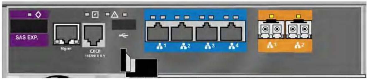
MANAGING THE ENCLOSURE (CLU)
Enclosure Management includes the following functions:
• "Viewing the Enclosures Summary (CLU)" on page 426
• “Viewing Enclosure Information (CLU)” on page 427
- “Making Enclosure Settings (CLU)” on page 427
• "Viewing Power Supply Status (CLU)" on page 428
- “Locating a Power Supply (CLU)” on page 429
• "Viewing Cooling Unit Status (CLU)" on page 429
• "Viewing Temperature Sensor Status (CLU)" on page 430
• "Viewing Voltage Sensor Status (CLU)" on page 430
• “Viewing Battery Information (CLU)” on page 431
- “Locating an Enclosure (CLU)” on page 432
VIEWING THE ENCLOSURES SUMMARY (CLU)
Enclosure Management includes information, status, settings and location. To access Enclosure Management:
-
From the Main Menu, highlight Subsystem Management and press Enter.
-
Highlight Enclosure Management and press Enter.
The following information is shown:
• Enclosure ID number
- Enclosure Type
- Operational Status
- Status Description (specific components in need of attention, if any)
VIEWING ENCLOSURE INFORMATION (CLU)
To view enclosure information:
- From the Main Menu, highlight Subsystem Management and press Enter.
- Highlight Enclosure Management and press Enter.
- Highlight the enclosure you want and press Enter.
You can monitor power supplies, cooling units, enclosure temperatures and voltages, and the battery.
ADJUSTABLE ITEMS
You can set or adjust the following items:
• Enclosure Warning and Critical temperature thresholds
• Controller Warning and Critical temperature thresholds
See "Making Enclosure Settings" below.
For information on Enclosure problems, see "Enclosure Problems" on page 623.
MAKING ENCLOSURE SETTINGS (CLU)
To make Enclosure settings:
- From the Main Menu, highlight Subsystem Management and press Enter.
- Highlight Enclosure Management and press Enter.
- Highlight the enclosure you want and press Enter.
- Highlight Enclosure Settings and press Enter.
- Highlight the Temperature Warning threshold you want to change.
- Press the backspace key to erase the current value.
- Type a new interval value in degrees C.
- Press Control-A to save your settings.
VIEWING FRU VPD INFORMATION (CLU)
FRU VPD refers to Vital Product Data (VPD) information about Field Replaceable Units (FRU) in the enclosure. The number and type of FRU depends on the subsystem model.
To view FRU VPD information:
- From the Main Menu, highlight Subsystem Management and press Enter.
- Highlight Enclosure Management and press Enter.
- Highlight the enclosure you want and press Enter.
- Highlight FRU VPD Information and press Enter.
Use this information when communicating with Technical Support and when ordering replacement units. For contact information, see “Contacting Technical Support” on page 666.
VIEWING POWER SUPPLY STATUS (CLU)
To view the status of the power supplies:
- From the Main Menu, highlight Subsystem Management and press Enter.
- Highlight Enclosure Management and press Enter.
- Highlight the enclosure you want and press Enter.
- Highlight Power Supplies and press Enter.
The screen displays the operational and fan status of Vess R2000's three power supplies. If any status differs from normal or the fan speed is below the Healthy Threshold value, there is a fan/power supply malfunction. See “Replacing a Power Supply” on page 540.
LOCATING A POWER SUPPLY (CLU)
To locate a power supply:
- From the Main Menu, highlight Subsystem Management and press Enter.
- Highlight Enclosure Management and press Enter.
- Highlight the enclosure you want and press Enter.
- Highlight Power Supplies and press Enter.
- Highlight Locate Power Supply and press Enter.
The LED on the selected power supply blinks for one minute.
VIEWING COOLING UNIT STATUS (CLU)
To view the status of the power supply fans:
- From the Main Menu, highlight Subsystem Management and press Enter.
- Highlight Enclosure Management and press Enter.
- Highlight the enclosure you want and press Enter.
- Highlight Cooling Units and press Enter.
The screen displays the status and speed of Vess R2000's cooling units, which are the power supply fans. If fan speed is below the Healthy Threshold, there is a malfunction.
VIEWING TEMPERATURE SENSOR STATUS (CLU)
To view the status of the temperature sensors:
- From the Main Menu, highlight Subsystem Management and press Enter.
- Highlight Enclosure Management and press Enter.
- Highlight the enclosure you want and press Enter.
- Highlight Temperature Sensors and press Enter.
If any temperature exceeds the Healthy Threshold value, there is an overheat condition in the enclosure. See “Making Enclosure Settings (CLU)” on page 427 and see “Enclosure Problems” on page 623.
VIEWING VOLTAGE SENSOR STATUS (CLU)
To view the status of the voltage sensors:
- From the Main Menu, highlight Subsystem Management and press Enter.
- Highlight Enclosure Management and press Enter.
- Highlight the enclosure you want and press Enter.
- Highlight Voltage Sensors and press Enter.
If any voltage is outside the Healthy Threshold values, there is a voltage malfunction in the enclosure. See “Enclosure Problems” on page 623.
VIEWING BATTERY INFORMATION (CLU)
This feature enables you monitor and recondition the subsystem battery or batteries.
- From the Main Menu, highlight Subsystem Management and press Enter.
- Highlight Enclosure Management and press Enter.
- Highlight the enclosure you want and press Enter.
- Highlight Batteries and press Enter.
- Highlight the battery you want to monitor and press Enter.
BATTERY NOTES
If a battery does not reflect normal conditions and it is not currently under reconditioning, run the Recondition function before you replace the battery. See Reconditioning a Battery (CLU).
Reconditioning fully discharges, then fully recharges the battery. During reconditioning, if the Adaptive Writeback Cache function is enabled, the controller cache is set to Write Thru. After reconditioning, the cache is reset to Write Back. See “Making Controller Settings (CLU)” on page 423.
If a battery reaches the threshold temperature while charging or discharging, the charge or discharge pauses and the blower runs at high speed until the battery temperature falls below the threshold.
If the battery does not maintain normal values after a Recondition, replace the battery. See “Replacing a Cache Backup Battery” on page 543.
RECONDITIONING A BATTERY (CLU)
To recondition the subsystem battery:
- From the Main Menu, highlight Subsystem Management and press Enter.
- Highlight Enclosure Management and press Enter.
- Highlight the enclosure you want and press Enter.
- Highlight Batteries and press Enter.
- Highlight the battery you want to recondition and press Enter.
- Highlight Start Reconditioning and press Enter.
- Press Y to confirm.
Reconditioning fully discharges, then fully recharges the battery. During reconditioning, if the Adaptive Writeback Cache function is enabled, the controller cache is set to Write Thru. After reconditioning, the cache is reset to Write Back. See “Making Controller Settings (CLU)” on page 423.
LOCATING AN ENCLOSURE (CLU)
This feature helps you identify the physical Vess R2000 enclosure you are working with through the CLU.
- From the Main Menu, highlight Subsystem Management and press Enter.
- Highlight Enclosure Management and press Enter.
- Highlight the enclosure you want and press Enter.
- Highlight Locate Enclosure and press Enter.
The LEDs on the front of the Vess R2000 blink for one minute.
VIEWING ENCLOSURE TOPOLOGY (CLU)
This feature displays the connection topology of the Vess R2000 subsystem. Topology refers to the manner in which the data paths among the enclosures are connected. There are three methods:
• Individual Subsystem – A single subsystem
- JBOD Expansion – Managed through one subsystem or head unit
- RAID Subsystem Cascading – Managed through one subsystem or head unit
For more information about connections, see “Making Management and Data Connections” on page 39.
To view enclosure topology:
- From the Main Menu, highlight Subsystem Management and press Enter.
- Highlight Enclosure Topology and press Enter.
The following information applies to the Head Unit:
• Enclosure number – 1
• Controller number – 1 or 2
- Port number
- Status – OK is normal. N/C is not connected
- Link Width
The following information applies to RAID cascaded units or JBOD expansion units:
- Connected EncIWWN – The subsystem identified by its World Wide Name (WWN)
- Connected (Encl, Ctrl, Port) – The subsystem's enclosure, controller, and port numbers where the data connection was made
• If there is no connection, the value shows N/A.
PHYSICAL DRIVE MANAGEMENT (CLU)
Physical Drive Management includes the following functions:
• "Viewing a List of Physical Drives (CLU)" on page 434
- “Making Global Physical Drive Settings (CLU)” on page 434
• "Viewing Physical Drive Information (CLU)" on page 436
- "Setting an Alias (CLU)" on page 436
- “Clearing Stale and PFA Conditions (CLU)” on page 437
• "Forcing a Physical Drive Offline (CLU)" on page 438
- "Locating a Physical Drive (CLU)" on page 439
VIEWING A LIST OF PHYSICAL DRIVES (CLU)
To view a list of physical drives:
From the Main Menu, highlight Physical Drive Management and press Enter.
The list of physical drives displays.
MAKING GLOBAL PHYSICAL DRIVE SETTINGS (CLU)
All physical drive settings are made globally, except for setting an alias, which applies to individual drives.
To make global physical drive settings:
- From the Main Menu, highlight Physical Drive Management and press Enter.
- Highlight Global Physical Drives Settings and press Enter.
- Change the following settings as required.
For SATA drives:
- Highlight Write Cache and press the spacebar to toggle between Enabled and Disabled.
-
Highlight Read Look Ahead Cache and press the spacebar to toggle between Enabled and Disabled.
-
Highlight CmdQueuing and press the spacebar to toggle between Enabled and Disabled.
- Highlight MediumErrorThreshold and press the backspace key to remove the current value, then type a new smaller value. See the comments on the next page.
- Highlight DMA Mode and press the spacebar to toggle through UDMA 0 to 6 and MDMA 0 to 2.
For SAS drives:
- Highlight Write Cache and press the spacebar to toggle between Enabled and Disabled.
- Highlight Read Look Ahead Cache and press the spacebar to toggle between Enabled and Disabled.
- Highlight CmdQueuing and press the spacebar to toggle between Enabled and Disabled.
- Highlight MediumErrorThreshold and press the backspace key to remove the current value, then type a new smaller value. See the comments below.
-
Highlight Read Cache and press the spacebar to toggle between Enabled and Disabled.
-
Press Control-A to save your settings.
See “Viewing Physical Drive Information” below to determine which functions your physical drives support.
Medium Error Threshold is the number of bad blocks tolerated before the controller marks the drive as Dead. The default setting is 64 blocks. A setting of zero disables the function. When disabled, no drives are marked offline even when errors are detected.
VIEWING PHYSICAL DRIVE INFORMATION (CLU)
To view information about a physical drive:
- From the Main Menu, highlight Physical Drive Management and press Enter.
- Highlight the physical drive you want and press Enter.
Basic information displays.
- Highlight Advanced Information and press Enter.
Advanced information displays.
VIEWING PHYSICAL DRIVE STATISTICS (CLU)
To view the statistics for the selected physical drive:
- From the Main Menu, highlight Physical Drive Management and press Enter.
- Highlight the physical drive you want and press Enter.
- Highlight Physical Drive Statistics and press Enter.
CLEARING STATISTICS
To clear physical drive statistics, see "Clearing Statistics (CLU)" on page 522.
SETTING AN ALIAS (CLU)
An alias is optional. To set an Alias for a physical drive:
- From the Main Menu, highlight Physical Drive Management and press Enter.
- Highlight the physical drive you want and press Enter.
- Type an alias into the field provided.
Maximum of 32 characters. Use letters, numbers, space between words and underscore.
- Press Control-A to save your settings.
CLEARING STALE AND PFA CONDITIONS (CLU)
The Clear Stale and Clear PFA functions only appear when those conditions exist on the physical drive. To clear a Stale or PFA condition on a physical drive:
- From the Main Menu, highlight Physical Drive Management and press Enter.
- Highlight the physical drive you want and press Enter.
- Highlight Clear Stale or Clear PFA and press Enter.
If a physical drive is still online and shows a PFA error but "Clear PFA" does not appear, use PDM to copy the data to a new physical drive. See "Running PDM on a Disk Array" on page 136.
If a physical drive is offline and shows a PFA error, rebuild the disk array. See "Rebuilding a Disk Array" on page 135. After rebuilding, the drive shows Stale. Run Clear Stale then run Clear PFA.
If the physical drive with a PFA error is a spare, you must delete the drive as a spare, then Clear PFA is available.
After you clear a PFA error, watch for another PFA error to appear. If it does, replace the physical drive.
This function enables you to force an online physical drive to go Offline.
The Force Offline function appears only for physical drives that are assigned to disk arrays.

Caution
Forcing a physical drive offline is likely to cause data loss. Back up your data before you proceed. Use this function only when required.

Important
Forcing a physical drive offline causes your logical drives to become degraded. If Auto Rebuild is enabled and a spare drive is available, the disk array begins rebuilding itself automatically.
To force a physical drive offline:
- From the Main Menu, highlight Physical Drive Management and press Enter.
- Highlight Global Physical Drives Settings and press Enter.
- Highlight the physical drive you want and press Enter.
- Highlight Force Offline and press Enter.
- Press Y to confirm.
LOCATING A PHYSICAL DRIVE (CLU)
This feature helps you identify a physical drive within the Vess R2000 enclosure you are working with through the CLU. To locate a physical drive:
- From the Main Menu, highlight Physical Drive Management and press Enter.
- Highlight Global Physical Drives Settings and press Enter.
- Highlight the physical drive you want and press Enter.
- Highlight Locate Physical Drive and press Enter.
The drive carrier status LED flashes for one minute.
Drive carrier status LED

MANAGING DISK ARRAYS (CLU)
Disk Array Management includes the following functions:
• "Viewing a List of Disk Arrays (CLU)" on page 441
- “Creating a Disk Array (CLU)” on page 441
- “Deleting a Disk Array (CLU)” on page 445
• “Making Disk Array Settings (CLU)” on page 446
• "Viewing Disk Array Information (CLU)" on page 447
- "Enabling Media Patrol, PDM, Power Management - Disk Array (CLU)" on page 448.
• "Preparing the Disk Array for Transport (CLU)" on page 449
- "Rebuilding a Disk Array (CLU)" on page 449
- “Running PDM on a Disk Array (CLU)” on page 450
- “Running Transition on a Disk Array (CLU)” on page 451
- "Locating a Disk Array (CLU)" on page 451
VIEWING A LIST OF DISK ARRAYS (CLU)
To view a list of disk arrays:
From the Main Menu, highlight Disk Array Management and press Enter.
The list of disk arrays displays.
CREATING A DISK ARRAY (CLU)
The CLU provides three methods of creating a disk array:
- Automatic – Creates a new disk array following a default set of parameters. Creates a hot spare drive for all RAID levels except RAID 0, when five or more unconfigured physical drives are available. You can accept or reject the proposed arrangement but you cannot modify it. See “Creating a Disk Array – Automatic”
- Express – You choose the parameters for a new disk array by specifying the characteristics you want. You can create multiple logical drives at the same time, however they are all identical. Creates a hot spare drive for all RAID levels except RAID 0. See “Creating a Disk Array – Express”
- Advanced – Enables you to specify all parameters for a new disk array, logical drives and spare drives. See “Creating a Disk Array – Advanced”
CREATING A DISK ARRAY — AUTOMATIC (CLU)
To create a disk array using the Automatic feature:
- From the Main Menu, highlight Disk Array Management and press Enter.
- Highlight Create New Array and press Enter.
- Highlight Configuration Method and press the spacebar to toggle to Automatic.
- Press Control-A to save your settings and move to the next screen.
-
Review the proposed configuration of disk array and logical drives.
-
To accept the proposed configuration and create the disk array and logical drives, highlight Save Configuration and press Enter.
- To reject the proposed configuration, highlight Cancel Array Configuration and press Enter. You return to the Disk Arrays Summary screen.
To create a disk array with different characteristics, repeat the steps above specifying different parameters but choose the Express or Advanced option.
CREATING A DISK ARRAY — EXPRESS (CLU)
To create a disk array using the Express feature:
- From the Main Menu, highlight Disk Array Management and press Enter.
- Highlight Create New Array and press Enter.
- Highlight Configuration Method and press the spacebar to toggle to Express.
-
Highlight the following options and press to spacebar to choose Yes or No:
-
Redundancy
- Capacity
- Performance
- Spare Drive
- Mixing SATA/SAS Drive
If you choose No, and you have both SATA and SAS drives, a separate array is created for each type of drive.
- Highlight Number of Logical Drives and press the backspace key to erase the current value, then enter the number of logical drives you want.
-
Highlight Application Type and press the spacebar to toggle though the applications and choose the best one for your disk array.
-
File Server
- Video Stream
- Transaction Data
- Transaction Log
-
Other
-
Press Control-A to save your settings and move to the next screen.
-
Review the proposed configuration of disk array and logical drives.
To accept the proposed configuration and create the disk array and logical drives, highlight Save Configuration and press Enter.
To reject the proposed configuration, highlight Cancel Array Configuration and press Enter. You
return to the Disk Arrays Summary screen.
To create a disk array with different characteristics, highlight Create New Array and press Enter. Repeat the steps above specifying different parameters. Or choose the Advanced option.
CREATING A DISK ARRAY — ADVANCED (CLU)
For more information on the choices below, see “Chapter 7: Technology Background”
To create a disk array using the Advanced feature:
- From the Main Menu, highlight Disk Array Management and press Enter.
- Highlight Create New Array and press Enter.
- Highlight Configuration Method and press the spacebar to toggle to Advanced.
Step 1 – Disk Array Creation
- If you want to specify an alias to the disk array, highlight Alias and type a name.
Maximum of 32 characters. Use letters, numbers, space between words and underscore. - Choose whether to enable Media Patrol, PDM, and Power Management.
- Choose a Media Type, HDD or SSD.
- Highlight Save Settings and Continue and press Enter.
- Highlight a physical drive you want to add to your array and press the spacebar to choose it.
Repeat this action until you have selected all the physical drives for your array. - Highlight Save Settings and Continue and press Enter.
Step 2 – Logical Drive Creation
- If you want to specify an alias to the logical drive, highlight Alias and type a name.
Maximum of 32 characters. Use letters, numbers, space between words and underscore.
-
Highlight RAID Level and press the spacebar to toggle though a list of available RAID levels.
-
If you want to create multiple logical drives, highlight Capacity, press the backspace key to remove the current value, then type a new smaller value.
-
RAID 30, 50 and 60 only. Highlight Number of Axles and press the spacebar to choose the number of axles.
See "RAID 60 Axles" on page 568 and "RAID 50 Axles" on page 565.
- For the following items, accept the default value or highlight and press the spacebar to choose a new value:
- Highlight Stripe and press the spacebar to toggle through stripe sizes and choose 64 KB, 128 KB, 256 KB, 512 KB, or 1 MB.
- Highlight Sector and press the spacebar to toggle through sector sizes and choose 512 B, 1 KB, 2 KB, or 4 KB.
- Highlight Write Policy and press the spacebar to toggle write cache policy between WriteBack and WriteThru (write though).
- Highlight Read Policy and press the spacebar to toggle read cache policy though ReadCache, ReadAhead, and NoCache.
- Highlight Preferred Controller ID and press the spacebar to toggle among 1, 2, or Automatic.
- Highlight PerfectRebuild and press the spacebar to toggle Enable or disable.
- Highlight Save Logical Drive and press Enter.
Step 3 – Summary
Review logical drives you are about to create for your new array. Then do one of the following actions:
- If you agree with the logical drives as specified, highlight Complete Disk Array Creation and press Enter.
- If you specified less than the full capacity for the logical drive in the previous screen, and you want to add another logical drive now, highlight Create New Logical Drive and press Enter.
- If you do not agree with the logical drives, highlight Return to Previous Screen and press Enter to begin the process again.
DELETING A DISK ARRAY (CLU)

Caution
When you delete a disk array, you delete all the logical drives and the data they contain. Back up all important data before deleting a disk array.
- From the Main Menu, highlight Disk Array Management and press Enter.
- Highlight the disk array you want to delete and press the spacebar to mark it.
The mark is an asterisk (*) to the left of the listing.
- Highlight Delete Marked Arrays and press Enter.
- Press Y to confirm the deletion.
- Press Y again to reconfirm.
MAKING DISK ARRAY SETTINGS (CLU)
To make disk array settings:
- From the Main Menu, highlight Disk Array Management and press Enter.
The list of disk arrays appears.
- Highlight the disk array you want and press the Enter.
-
Make settings changes as required:
-
Enter, change or delete the alias in the Alias field Maximum of 32 characters; letters, numbers, space between characters, and underline.
• Media Patrol – Highlight and press the spacebar to toggle between enable and disable. - PDM – Highlight and press the spacebar to toggle between enable and disable.
-
Power Management – Highlight and press the spacebar to toggle between enable and disable.
-
Press Control-A to save your settings.

Notes
You can also enable or disable Media Patrol for the entire RAID system. See "Making Background Activity Settings" on page 495.
Power Management must be enabled on the disk array for the HDD Power Saving settings to be effective. See “Making Disk Array Settings (CLU)” on page 446.
Power management is limited to the features your HDDs actually support.
VIEWING DISK ARRAY INFORMATION (CLU)
-
From the Main Menu, highlight Disk Array Management and press Enter.
-
Highlight the disk array you want and press Enter.
The information and settings screen appears.
- Highlight any of the following and press Enter to view a list of:
• Physical drives in this array
• Logical drives in this array
- Spare drives in this array, dedicated and global
DISK ARRAY OPERATIONAL STATUS
- OK – This is the normal state of a logical drive. When a logical drive is Functional, it is ready for immediate use. For RAID Levels other than RAID 0 (Striping), the logical drive has full redundancy.
- Synchronizing – This condition is temporary. Synchronizing is a maintenance function that verifies the integrity of data and redundancy in the logical drive. When a logical drive is Synchronizing, it functions and your data is available. However, access is slower due to the synchronizing operation.
- Critical/Degraded – This condition arises as the result of a physical drive failure. A degraded logical drive still functions and your data is still available. However, the logical drive has lost redundancy (fault tolerance). You must determine the cause of the problem and correct it.
- Rebuilding – This condition is temporary. When a physical drive has been replaced, the logical drive automatically begins rebuilding in order to restore redundancy (fault tolerance). When a logical drive is rebuilding, it functions and your data is available. However, access is slower due to the rebuilding operation.
- Transport Ready – After you perform a successful Prepare for Transport operation, this condition means you can remove the physical drives of this disk array and move them to another enclosure or different drive slots. After you relocate the physical drives, the disk array status shows OK.
ACCEPTING AN INCOMPLETE ARRAY (CLU)
This condition is the result of a missing physical drive. See "Incomplete Array" on page 215 before you use this function. To accept an incomplete array:
- From the Main Menu, highlight Disk Array Management and press Enter.
- Highlight the disk array you want and press Enter.
- Highlight Accept Incomplete Array and press Enter.
ENABLING MEDIA PATROL, PDM, POWER MANAGEMENT - DISK ARRAY (CLU)
Media Patrol checks the magnetic media on physical drives. Predictive Data Migration (PDM) migrates data from the suspect physical drive to a spare drive before the physical drive fails. Power Management parks the heads, spins down, and stops rotation after a set period of time to reduce power consumption.
Media Patrol, PDM, and Power Management are enabled by default. Enabled is the recommended setting for both features.
To enable Media Patrol, PDM, and Power Management on a disk array:
- From the Main Menu, highlight Disk Array Management and press Enter.
- Highlight the disk array you want and press Enter.
- Highlight Media Patrol and press the spacebar to toggle between Enable and Disable.
- Highlight PDM and press the spacebar to toggle between Enable and Disable.
- Highlight Power Management and press the spacebar to toggle between Enable and Disable.
- Press Control-A to save your settings.
See “Running PDM on a Disk Array (CLU)” on page 450 and “Making Background Activity Settings” on page 495.
For Power Management settings, see "Making Controller Settings (CLU)" on page 423.
PREPARING THE DISK ARRAY FOR TRANSPORT (CLU)
To run the Transport function on a disk array:
- From the Main Menu, highlight Disk Array Management and press Enter.
- Highlight the disk array you want and press Enter.
- Highlight Transport and press Enter.
- Press Y to confirm.
REBUILDING A DISK ARRAY (CLU)
Before you can rebuild, you must have a replacement or target physical drive of adequate capacity for your disk array.
To rebuild a disk array:
- From the Main Menu, highlight Disk Array Management and press Enter.
- Highlight the disk array you want and press Enter.
- Highlight Background Activities and press Enter.
- Highlight Rebuild and press Enter.
Default source and target drives are shown with possible alternative choices.
-
To choose different drive, highlight the drive, press the backspace key to remove the current number, then type a new number.
-
Highlight Start and press Enter.
For rebuild rate, see "Making Background Activity Settings" on page 495.
RUNNING MEDIA PATROL ON A DISK ARRAY (CLU)
Media Patrol is a routine maintenance procedure that checks the magnetic media on each disk drive. If Media Patrol encounters a critical error, it triggers PDM if PDM is enabled on the disk array.
See "Enabling Media Patrol, PDM, Power Management - Disk Array (CLU)" on page 448.
For Media Patrol rate, see "Making Background Activity Settings" on page 495.
RUNNING PDM ON A DISK ARRAY (CLU)
Predictive Data Migration (PDM) migrates data from the suspect physical drive to a spare drive before the physical drive fails.
Before you can run PDM, you must have a replacement or target physical drive of adequate capacity for your disk array.
To run PDM on a disk array:
- From the Main Menu, highlight Disk Array Management and press Enter.
- Highlight the disk array you want and press Enter.
- Highlight Background Activities and press Enter.
- Highlight Predictive Data Migration and press Enter.
Default source and target drives are shown with possible alternative choices.
- To choose different drive, highlight the drive, press the backspace key to remove the current number, then type a new number.
- Highlight Start and press Enter.
See “Enabling Media Patrol, PDM, Power Management - Disk Array (CLU)” on page 448.
For PDM rate, see "Making Background Activity Settings" on page 495.
RUNNING TRANSITION ON A DISK ARRAY (CLU)
Transition is the process of replacing a revertible spare drive that is currently part of a disk array with an unconfigured physical drive or a non-revertible spare drive. For more information, see "Transition" on page 193.
In order to run Transition:
• The spare drive must be Revertible.
- You must have an unconfigured physical drive of the same or larger capacity to replace the spare drive.
To run Transition on a disk array:
- From the Main Menu, highlight Disk Array Management and press Enter.
- Highlight the disk array you want and press Enter.
- Highlight Background Activities and press Enter.
- Highlight Transition and press Enter.
Default source and target drives are shown with possible alternative choices. - To choose different drive, highlight the drive, press the backspace key to remove the current number, then type a new number.
- Highlight Start and press Enter.
For transition rate, see "Making Background Activity Settings" on page 495.
LOCATING A DISK ARRAY (CLU)
This feature helps you identify the physical drives assigned to the disk array you are working with in the CLU.
To locate a disk array:
-
From the Main Menu, highlight Disk Array Management and press Enter.
-
Highlight the disk array you want and press Enter.
-
Highlight Locate Disk Array and press Enter.
The drive carrier status LEDs flash for one minute.
MANAGING SPARE DRIVES (CLU)
Spare Drive Management includes the following functions:
• "Viewing a list of Spare Drives (CLU)" on page 452
- “Creating a Spare Drive (CLU)” on page 452
- “Making Spare Drive Settings (CLU)” on page 453
• "Running Spare Check (CLU)" on page 454
- "Deleting a Spare Drive (CLU)" on page 454
VIEWING A LIST OF SPARE DRIVES (CLU)
To view a list of spare drives:
From the Main Menu, highlight Spare Drive Management and press Enter.
A list of the current spare drives appears, including the following parameters:
• ID number
• Operational Status
• Physical Drive ID number
- Configured Capacity
- Revertible – The spare drive returns to spare status after you replace the failed drive in the disk array. See “Transition” on page 356 for more information.
- Type – Global (all disk arrays) or Dedicated (to specified disk arrays)
• Dedicated to Array – The array to which a dedicated spare is assigned
For more information, see "Disk Arrays" on page 100.
CREATING A SPARE DRIVE (CLU)
Only unconfigured physical drives can be used to make spares. Check your available drives under Physical Drive Management. Also see "Managing Physical Drives" on page 100.
- From the Main Menu, highlight Spare Drive Management and press Enter.
- Highlight Create New Spare Drive and press Enter.
A default physical drive is shown with possible alternative choices.
- To choose different drive, highlight the drive, press the backspace key to remove the current number, then type a new number.
- Highlight Revertible and press the spacebar to toggle between Yes and No.
A revertible drive can be returned to spare status after you replace the failed drive in a disk array. See "Transition" on page 101 for more information.
- Highlight Spare Type and press the spacebar to toggle between Dedicated and Global.
Dedicated means this spare drive can only be used with the specified disk arrays. Global means this spare drive can be used by any disk array.
If you chose Dedicated, a default disk array is shown with possible alternative choices.
To choose different array, highlight the array and press the backspace key to erase the current number, then type the new number.
- Press Control-A to save the spare drive.
MAKING SPARE DRIVE SETTINGS (CLU)
To change spare drive settings:
- From the Main Menu, highlight Spare Drive Management and press Enter.
A list of the current spare drives appears, including the following parameters:
- Highlight the spare drive you want to change and press Enter.
-
Highlight the setting you want to change:
-
Revertible – A revertible drive can be returned to spare status after you replace the failed drive in a disk array. See “Transition” on page 356 for more information.
-
Type – Dedicated means this spare drive can only be used with the specified disk arrays. Global means this spare drive can be used by any disk array.
-
Press the spacebar to toggle between the choices.
- For dedicated spares, type the array number the spare is assigned to.
- Press Control-A to save your settings.
RUNNING SPARE CHECK (CLU)
To run Spare Check:
- From the Main Menu, highlight Spare Drive Management and press Enter.
A list of the current spare drives appears.
-
Highlight the spare drive you want to check and press Enter.
-
Highlight Start Spare Check and press Enter.
The results appear next to Spare Check Status in the same window. Healthy means normal.
DELETING A SPARE DRIVE (CLU)

Caution
If the spare drive you delete is the only spare, the controller does not rebuild a critical array until you provide a new spare drive.
To delete a spare drive:
- From the Main Menu, highlight Spare Drive Management and press Enter.
A list of the current spare drives appears.
- Highlight the spare drive you want to delete and press the spacebar to mark it.
The mark is an asterisk (*) to the left of the listing.
-
Highlight Delete Marked Spare Drives and press Enter.
-
Press Y to confirm the deletion.
MANAGING LOGICAL DRIVES (CLU)
Logical drive management includes:
- “Creating a Logical Drive (CLU)” on page 455
- "Deleting a Logical Drive (CLU)" on page 457
- “Viewing the Logical Drive Check Table (CLU)” on page 458
- “Making Logical Drive Settings (CLU)” on page 459
- “Initializing a Logical Drive (CLU)” on page 459
- “Running Redundancy Check (CLU)” on page 460
- “Locating a Logical Drive (CLU)” on page 461
- "Migrating a Logical Drive (CLU)" on page 461
- “Creating a LUN Clone (CLU)” on page 463
For LUN mapping, see "Working with LUN Mapping (CLU)" on page 499.
CREATING A LOGICAL DRIVE (CLU)
You can create logical drives on existing disk arrays if there is available space in the array.
To create a logical drive from an existing disk array:
- From the Main Menu, highlight Disk Array Management and press Enter.
- Highlight the disk array in which you want to create a logical drive and press Enter.
- Highlight Logical Drives in the Disk Array and press Enter.
- Highlight Create New Logical Drive and press Enter.
The Disk Array ID number and Maximum capacity available for the new logical drive are displayed.
-
Highlight the following parameters and press the backspace key to erase the current value:
-
Alias – Type an alias into the field, if desired. Maximum of 32 characters. Use letters, numbers, space between words and underscore.
- RAID Level - Press the spacebar to toggle though a list of available RAID levels.
-
Capacity – Maximum capacity shown. Enter a smaller capacity if desired.
-
Highlight the following parameters and press the spacebar to toggle though the available choices:
-
Stripe size – Press the spacebar to choose: 64 KB, 128 KB, 256 KB, 512 KB, or 1 MB.
- Sector size – Press the spacebar to choose: 512 B; 1 KB, 2 KB, or 4 KB.
- Write Policy – Press spacebar to choose: Write Back or Write Through.
-
Read Policy – Press spacebar to choose: No Cache, Read Cache, or Read Ahead Cache.
-
Highlight Preferred Controller ID and press the spacebar to toggle among 1, 2, or Automatic.
- Highlight PerfectRebuild and press the spacebar to toggle Enable or disable.
- RAID 30, 50 and 60 only. Highlight Number of Axles and press the spacebar to choose the number of axles.
- Highlight Save Logical Drive and press Enter.

Note
If you did not use all of the available capacity of the disk array, you can create an additional logical drive at this point.
DELETING A LOGICAL DRIVE (CLU)

Caution
When you delete a logical drive, you delete all the data it contains. Back up all important data before deleting a logical drive.
To delete a logical drive from a disk array:
- From the Main Menu, highlight Disk Array Management and press Enter.
- Highlight the disk array that contains the logical drive you want to delete and press Enter.
- Highlight Logical Drives in the Disk Array and press Enter.
- Highlight the logical drive you want to delete and press the spacebar to mark it.
The mark is an asterisk (*) to the left of the listing. - Highlight Delete Marked Logical Drives and press Enter.
- Press Y to confirm the deletion.
Press Y again to re-confirm.
VIEWING LOGICAL DRIVE INFORMATION (CLU)
To view logical drive information:
-
From the Main Menu, highlight Logical Drive Management and press Enter.
-
Highlight the logical drive you want and press Enter.
The information and settings screen appears.
- Highlight any of the following and press Enter to view more information:
- Check Table – Read Check, Write Check, and Inconsistency Check Tables
• Logical Drive Statistics
VIEWING LOGICAL DRIVE STATISTICS (CLU)
To view logical drive information:
- From the Main Menu, highlight Logical Drive Management and press Enter.
- Highlight the logical drive you want and press Enter.
The information and settings screen appears.
- Highlight Logical Drive Statistics and press Enter.
The statistics screen appears.
To clear logical drive statistics, see "Clearing Statistics (CLU)" on page 522.
VIEWING THE LOGICAL DRIVE CHECK TABLE (CLU)
To view logical drive information:
- From the Main Menu, highlight Logical Drive Management and press Enter.
- Highlight the logical drive you want and press Enter.
- Highlight Check Table and press Enter.
- Highlight one of the following options and press Enter:
• Show All Records
- Read Check Table
- Write Check Table
• Inconsistent Check Table
MAKING LOGICAL DRIVE SETTINGS (CLU)
To make Logical Drive settings:
- From the Main Menu, highlight Logical Drive Management and press Enter.
- Highlight the logical drive you want and press Enter.
-
For the following items, accept the existing setting choose a new one:
-
Highlight Alias and type an alias into the field provided.
• Maximum of 32 characters. Use letters, numbers, space between words and underscore. An alias is optional. - Highlight WritePolicy and press the spacebar to toggle between WriteBack and WriteThru (write though).
- Highlight ReadPolicy and press the spacebar to toggle though ReadCache, ReadAhead and None.
• Highlight Preferred Controller ID and press the spacebar to toggle between 1 and 2. -
Highlight PerfectRebuild and press the spacebar to toggle between Enable and Disable. Note that once PerfectRebuild is disbaled it can not be enabled again.
-
Press Control-A to save your settings.
INITIALIZING A LOGICAL DRIVE (CLU)
This function sets all data bits in the logical drive to zero.

Warning
When you initialize a logical drive, all the data on the logical drive is lost. Backup any important data before you initialize a logical drive.
To initialize a logical drive:
- From the Main Menu, highlight Logical Drive Management and press Enter.
- Highlight the logical drive you want and press Enter.
- Highlight Background Activities and press Enter.
- Highlight Start Initialization and press Enter.
The initialization parameters appear.
- Initialization pattern – The default 00000000 is best for most applications
- Quick Initialization – Yes means only the first and last sections of the logical drives are initialized. No means the entire logical drive is initialized.
To change a parameter, highlight it and press the backspace key to erase the current value, then type the new value.
- Highlight Start and press Enter.
If necessary, you can pause and resume or stop and restart the Initialization. You cannot access the logical drive until Initialization has finished.
For initialization rate, see "Making Background Activity Settings" on page 495.
RUNNING REDUNDANCY CHECK (CLU)
Redundancy Check is a maintenance procedure for logical drives in fault-tolerant disk arrays that ensures all the data matches exactly.
To run Redundancy Check:
- From the Main Menu, highlight Logical Drive Management and press Enter.
- Highlight the logical drive you want and press Enter.
- Highlight Background Activities and press Enter.
- Highlight Start Redundancy Check and press Enter.
The redundancy check parameters appear.
• Auto Fix – Corrects inconsistencies automatically
- Pause On Error – Pauses the Redundancy Check when an error is found
To change a parameter, highlight it and press the backspace toggle between Yes and No.
- Highlight Start and press Enter.
If necessary, you can pause and resume or stop and restart the Redundancy Check. You can use the logical drive while Redundancy Check is running.
For Redundancy Check rate, see "Making Background Activity Settings" on page 495.
LOCATING A LOGICAL DRIVE (CLU)
This feature helps you identify the physical drives assigned to the logical drive you are working with in the CLU. To locate a logical drive:
- From the Main Menu, highlight Logical Drive Management and press Enter.
- Highlight the logical drive you want and press Enter.
- Highlight Locate Logical Drive and press Enter.
The drive carrier status LEDs flash for one minute.
Drive carrier status LED
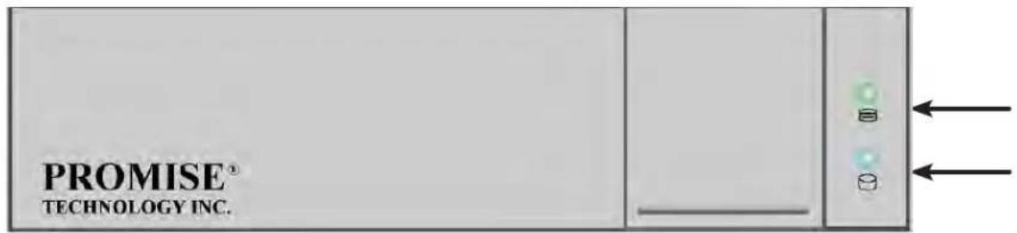
MIGRATING A LOGICAL DRIVE (CLU)
In order to migrate RAID level, you may have to add physical drives. For more information, see “RAID Level Migration” on page 108.
To migrate a logical drive:
- From the Main Menu, highlight Disk Array Management and press Enter.
- Highlight the disk array you want and press Enter.
- Highlight Background Activities and press Enter.
- Highlight Migration and press Enter.
- Highlight the physical drives you want to add and press the spacebar to choose them.

Note
You can add physical drives to a RAID 50 or 60 array but you cannot change the number of axles.
If you add an odd number of physical drives to a RAID 10 array, it becomes a RAID 1E array by default.
- Highlight Save Settings and Continue and press Enter.
- Highlight a logical drive in the list that you want to migrate and press Enter.
- Highlight RAID Level and press the spacebar to toggle through the available RAID levels.
- Optional. If you want to increase capacity of the logical drive, highlight Expand Capacity and press the spacebar to toggle to Yes.
Highlight Capacity, press the backspace key to erase the current capacity and type in the new value.
The new value must be equal or larger than the current capacity.
- Highlight Save Logical Drive and press Enter.
The screen returns to Disk Array Migration Logical Drives.
At this point, if you have other logical drives in the same disk array, you can choose them for migration at the same time.
- Highlight Complete Disk Array Migration and press Enter.
- Press Y to confirm.
The screen returns to Disk Arrays Summary.
For migration rate, see "Making Background Activity Settings" on page 495.
CREATING A LUN CLONE (CLU)
A LUN clone is an exact copy of the original LUN or logical drive, including all the data it contains, at one point in time. Use a LUN clone as a backup or to migrate a LUN from one system to another.
LUN CLONE OPTIONS
The Vess R2000 includes a new LUN Clone option, the Online LUN Clone. This is used to create a copy of a LUN without stopping I/O on the source LUN. All data on the source LUN is copied and synchronized in a background operation. The cloning process runs in the background and continues until it is explicitly stopped by the administrator. This is in contrast to the Offline LUN Clone which requires that the source LUN go offline during the process.
First decide if the LUN is cloned to either a Disk Array or another Logical Drive, then choose the Offline or Online option for the method used.

Important
The action of creating an Offline LUN momentarily takes the original LUN or logical drive offline, meaning nobody can read or write to it.
A LUN clone has the same capacity, stripe size, read and write policies as the original LUN. However, the LUN clone can be a different RAID level. The choice of RAID levels depends on the disk array. And if you have multiple disk arrays, you can create the LUN clone on a different disk array than the original LUN.
This action requires Super User or Power User privileges.
To create a LUN clone of a logical drive:
- From the Main Menu, highlight Logical Drive Management and press Enter.
- Highlight the logical drive you want to clone and press Enter.
- Highlight LUN Clone and press Enter.
- Highlight RAID Target and toggle LD (Logical Drive) or DA (Disk Array).
If DA is chosen, an additional option appears to choose RAID level of the copy.
For DA option, highlight RAID Level of Copies, and enter RAID level for the LUN Clone on the target Disk Array.
- Highlight Clone type and toggle to select Online or Offline for the type of cloning process.
For Online Clone type, an additional option appears to enter a write expiration time in minutes.
For Online Clone, highlight Mirror Write End Time and type in a value for the number of minutes allowed for the Online Clone.
- Highlight Save Settings and Continue and press Enter.
- Highlight the disk array you want to use and press the Spacebar to mark it.
- Highlight Save Settings and Continue and press Enter.
- Highlight the Number of Copies field and type the number of LUN clones you want to create.
You can create up to 8 clones of a LUN at a time.
- Highlight Start and press enter to begin the cloning process.
- Press any key to continue.
- Press Y to confirm LUN clone creation. Press N to abort the LUN Clone.
The cloning progress bar displays.
Note the Target Logical Drive ID. Use this number to identify the LUN clone in the Logical Drive list.
If you chose a redundant RAID level, the LUN clone is automatically synchronized after creation.
After the LUN clone is created, you can manage it like any other logical drive. See "Making Spare Drive Settings
(CLU)" on page 453, "Locating a Logical Drive (CLU)" on page 461, and "Deleting a Logical Drive (CLU)" on page 457.
For users to access the LUN clone, you must map it to an initiator. See "Working with LUN Mapping (CLU)" on page 499
MANAGING THE NETWORK CONNECTION (CLU)
Network Management deals with network connections and settings for the Vess R2000's Management ports. Each Management Port can be configured:
- “Making Virtual Management Port Settings (CLU)” on page 465
- “Making Maintenance Mode Settings (CLU)” on page 467
MAKING VIRTUAL MANAGEMENT PORT SETTINGS (CLU)
The Vess R2000 subsystem has a virtual management port, enabling you to log into a Vess R2000 with dual controllers using one IP address.
Before you change settings, please see "About IP Addresses" on page 110.
You initially made these settings during subsystem setup. You can change them later as required.

Caution
Changing virtual management port settings can interrupt your network connection and require you to log in again.
MAKING AUTOMATIC SETTINGS
Automatic settings require a DHCP server on your network. DHCP is currently supported on IPv4 only.
To enable automatic management port settings:
- From the Main Menu, highlight Network Management and press Enter.
- Highlight the protocol family (IPv4 or IPv6) you want and press Enter.
- Highlight Network Settings and press Enter.
- Highlight DHCP and press the spacebar to toggle to Enabled.
- Press Control-A to save your settings.
MAKING MANUAL SETTINGS
- From the Main Menu, highlight Network Management and press Enter.
- Highlight the protocol family (IPv4 or IPv6) you want and press Enter.
- Highlight Network Settings and press Enter
- Highlight DHCP and press the spacebar to toggle to Disabled.
DHCP is currently supported by and does not appear under IPv6.
-
Highlight each of the following and press the backspace key to erase the current value, then type the new value.
-
IP Address
- Subnet Mask
-
Default Gateway IP Address
• DNS Server IP Address -
Press Control-A to save your settings.
MAKING MAINTENANCE MODE SETTINGS (CLU)
Each controller has its own IP addresses for access when the controller goes into maintenance mode. For more information, see "Maintenance Mode" on page 112.
Before you change settings, please see "About IP Addresses" on page 36.
MAKING AUTOMATIC SETTINGS
- From the Main Menu, highlight Network Management and press Enter.
- Highlight Maintenance Mode Network Configuration and press Enter.
- Highlight the controller (CId 1 or 2) and protocol family (IPv4 or IPv6) you want and press Enter.
- Highlight DHCP and press the spacebar to toggle to Enabled.
- Press Control-A to save your settings.
MAKING MANUAL SETTINGS
- From the Main Menu, highlight Network Management and press Enter.
- Highlight Maintenance Mode Network Configuration and press Enter.
- Highlight the controller (CId 1 or 2) and protocol family (IPv4 or IPv6) you want and press Enter.
- Highlight DHCP and press the spacebar to toggle to Disabled.
-
Highlight each of the following and press the backspace key to erase the current value, then type the new value.
-
IP Address
- Subnet Mask
-
Default Gateway IP Address
• DNS Server IP Address -
Press Control-A to save your settings.
MANAGING FIBRE CHANNEL CONNECTIONS (CLU)
The Fibre Channel Management option appears only with Vess R2000 Fibre Channel models. Fibre Channel Management includes the following functions:
- "Viewing Node Information (CLU)" on page 468
- “Viewing Fibre Channel Port Information” on page 468
- “Making Fibre Channel Port Settings (CLU)” on page 469
• "Viewing Fibre Channel Port Statistics (CLU)" on page 470
• "Viewing SFP Information (CLU)" on page 471
• "Viewing Fibre Channel Initiators (CLU)" on page 473
Also see: "Adding an FC Initiator" on page 220 and "Deleting an FC Initiator" on page 221.
VIEWING NODE INFORMATION (CLU)
These functions affect both Vess R2000 Fibre Channel ports.
- From the Main Menu, highlight Fibre Channel Management and press Enter.
- Highlight Fibre Channel Node and press Enter.
Node information appears. There are no user settings on this screen.
VIEWING FIBRE CHANNEL PORT INFORMATION
To view Fibre Channel port information:
- From the Main Menu, highlight Fibre Channel Management and press Enter.
- Highlight Fibre Channel Ports and press Enter.
Highlight the port you want and press Enter.
VIEWING FIBRE CHANNEL LOGGED-IN DEVICES (CLU)
To view a list of logged-in devices:
- From the Main Menu, highlight Fibre Channel Management and press Enter.
- Highlight Fibre Channel Ports and press Enter.
- Highlight the port you want and press Enter.
- Highlight Logged In Devices and press Enter.
If a Fibre Channel switch is attached, it also appears in this list.
MAKING FIBRE CHANNEL PORT SETTINGS (CLU)
To make Fibre Channel port settings:
- From the Main Menu, highlight Fibre Channel Management and press Enter.
- Highlight Fibre Channel Ports and press Enter.
- Highlight the port you want and press Enter.
-
Highlight Fibre Channel Port Settings and press Enter.
-
Highlight the following parameters and press the spacebar to toggle though the choices:
-
Configured Link Speed – 8 Gb/s, 4 Gb/s, 2 Gb/s, or Automatic selection
-
Configured Topology – NL-Port (Arbitrated Loop), N-Port (Point to Point) or Automatic selection
-
Highlight Hard ALPA and press the backspace key to erase the current value, then type the new value.
The range is 0 to 255. 255 disables this feature.
- Press Control-A to save your settings.
The table below shows the type of attached topology you achieve based on your connection type and the configured topology you choose:
| Fibre Channel Attached Topology | ||
| Configured Topology | ||
| Connection Type N-Port NL-Port | ||
| Switch | Fabric Direct Public | Loop |
| Direct Point-to-Point Private | Loop | |
Example 1: If you connect the Vess R2000 to a Fibre Channel switch and choose NL-Port topology, you create a Public Loop attached topology.
Example 2: If you have a Point to Point attached topology, you made a direct connection (no switch) and chose N-port topology.

Note
In some cases, HBA settings to N-Port only work if connected to the switch. Refer to your HBA manual for more information.
VIEWING FIBRE CHANNEL PORT STATISTICS (CLU)
To view Fibre Channel port statistics:
- From the Main Menu, highlight Fibre Channel Management and press Enter.
- Highlight Fibre Channel Ports and press Enter.
Highlight the port you want and press Enter. - Highlight Fibre Channel Port Statistics and press Enter.
VIEWING SFP INFORMATION (CLU)
To view information about the SFPs (small form-factor pluggable transceivers):
- From the Main Menu, highlight Fibre Channel Management and press Enter.
- Highlight Fibre Channel Ports and press Enter.
- Highlight the port you want and press Enter.
- Highlight Fibre Channel Port SFP and press Enter.
The screen displays information about the SFP transceiver. There are no user settings on this screen.
VIEWING FIBRE CHANNEL PORT STATISTICS (CLU)
To view port statistics:
- From the Main Menu, highlight Fibre Channel Management and press Enter.
- Highlight Fibre Channel Ports and press Enter.
- Highlight the port you want and press Enter.
- Highlight Fibre Channel Port Statistics and press Enter.
This screen displays statistics for this port. There are no user settings on this screen.
CLEARING STATISTICS
To clear statistics, see "Clearing Statistics (CLU)" on page 522.
PROPERTY DEFINITIONS
Definitions of the properties for which statistical information is reported appears in the list below.
- TimeLastReset – Time in minutes since the system has been running.
- FramesSent – Number of frames sent since last reset.
- FramesReceived – Number of frames received since last reset.
- WordsSent – Number of words sent since last reset.
- WordsReceived – Number of words received since last reset.
- LIPCount – Loop Initialization Primitive Sequence. This primitive sequence applies only to the arbitrated
loop topology. It is transmitted by an L_Port to initialize or re-initialize the loop.
- NOSCount – Not Operational Primitive Sequence. This primitive sequence is used during link initialization between two N_Ports in the point-to-point topology or an N_Port and an F_Port in the fabric topology. NOS is sent to indicate that the transmitting port has detected a link failure or is offline. The expected response to a port sending NOS is the OLS primitive sequence.
- ErrorFrames – FC devices propagate handshake signals back-and-forth requesting and acknowledging each byte transferred. FC transfers occur in one frame of data at a time. In this case, the value reflects the number of frames with errors.
- DumpedFrames – This field specifies the number of frames dumped due to a lack of host buffers.
- LinkFailureCount – Number of times the link has failed. Can be caused by a disconnected link or a bad fiber element.
- LossSyncCount – Number of times a loss of sync has occurred since last reset.
- PrimitiveSeqErrorCount – An ordered set transmitted repeatedly and used to establish and maintain a link. LR, LRR, NOS, and OLS are primitive sequences used to establish an active link in a connection between two N_Ports or an N_Port and an F_Port.
LIP, LPB, and LPE are primitive sequences used in the Arbitrated Loop topology for initializing the loop and enabling or disabling an L_Port.
- InvalidWordSentCount – Number of invalid words sent since last reset.
- InvalidCRCCount – Invalid Cyclical Redundancy Count. Number of frames received with an invalid CRC since last reset.
- InitiatorIOCount – I/O Count on the initiator on the host side.
VIEWING FIBRE CHANNEL INITIATORS (CLU)
LUN Mapping must be enabled in order for Vess R2000 to recognize a Fibre Channel. See “Enabling LUN Mapping (CLU)” on page 499.
To view Fibre Channel initiators:
- From the Main Menu, highlight Fibre Channel Management and press Enter.
- Highlight Fibre Channel Initiators and press Enter.
A list of all currently logged-in initiators appears on the screen.
MANAGING ISCSI CONNECTIONS (CLU)
• “Viewing iSCSI Target Information (CLU)” on page 475
- “Making iSCSI Target Settings (CLU)” on page 476
• "Viewing a List of iSCSI Ports (CLU)" on page 477
• "Viewing iSCSI Port Information (CLU)" on page 477
• "Viewing a List of iSCSI Portals (CLU)" on page 479
• “Viewing iSCSI Portal Information (CLU)” on page 480
• “Adding iSCSI Portals (CLU)” on page 481
- “Making iSCSI Portal Settings (CLU)” on page 482
- "Deleting iSCSI Portals (CLU)" on page 483
- “Deleting an iSCSI Session (CLU)” on page 484
- "Viewing iSCSI Session Information (CLU)" on page 485
• “Making iSCSI iSNS Settings (CLU)” on page 487
• "Viewing a List of iSCSI CHAPs (CLU)" on page 488
• “Adding iSCSI CHAPs (CLU)” on page 488
• “Deleting iSCSI CHAPs (CLU)” on page 489
- "Pinging a Host or Server on the iSCSI Network (CLU)" on page 490
• "Viewing a List of iSCSI Trunks (CLU)" on page 491
• "Adding iSCSI Trunks (CLU)" on page 491
• "Making iSCSI Trunk Settings (CLU)" on page 492
- “Deleting iSCSI Trunks (CLU)” on page 493
VIEWING A LIST OF ISCSI TARGETS (CLU)
A target is a logical drive on the Vess R2000 subsystem.
The default target exposes all logical drives and is associated with all portals on the subsystem.
To view a list of iSCSI targets:
-
From the Main Menu, highlight iSCSI Management and press Enter.
-
Highlight iSCSI Targets and press Enter.
The list of iSCSI Targets displays.
• ID – Target number. 0 is the default target.
- Alias – User assigned name of the target
- AssignedPortals – portals assigned to the target
VIEWING ISCSI TARGET INFORMATION (CLU)
To view information for an iSCSI target:
-
From the Main Menu, highlight iSCSI Management and press Enter.
-
Highlight iSCSI Targets and press Enter.
The list of iSCSI Targets displays.
- Highlight the target you want to change and press Enter.
The target information screen displays. Information includes:
- TargetName – iSCSI qualified name (iqn) of this target.
- TargetAlias – Maximum of 32 characters. Use letters, numbers, space between words, and underscore. An alias is optional.*
• TargetStatus – Up or down. - ErrorRecovLevel – Error recovery level supported.
- ImmediateData – Enables the initiator to send unsolicited data with the iSCSI command PDU.
- MaxConnection – Maximum number of connections.
- DataPDUInOrder – Enables placement of data in PDU order.
- InitialR2T – Allows initiator to begin sending data to a target without receiving a ready to transfer command.
-
DataSeqInOrder – Enables placement of data in sequential order.
-
OutStandingR2T – Maximum number of R2T PDUs the target can have outstanding for a single iSCSI command.
- MaxBurstLen – Maximum length of a solicited data sequence in bytes.
- DefTimeToWait – After a dropped connection, the number of seconds to wait before attempting to reconnect.
- DefTimeToRetain – Number of seconds after time to wait (above) before reassigning outstanding commands.
- HeaderDigest – Enables the use of header digest (CRC). Enabled or disabled.*
- DataDigest – Enables the use of a data digest (CRC). Enabled or disabled.*
- UniCHAPAuthen – Uni-directional (peer) CHAP authentication, enabled or disabled.*
- BiCHAPAuthen – Bi-directional (local) CHAP authentication, enabled or disabled.*
- FirstBurstLen – First burst length in bytes.
- AssignedPortals – Portals assigned to this target.
- NOP-In: Check iSCSI connection status*
Items marked with an asterisk (*) are adjustable under “Making iSCSI Target Settings (CLU)” on page 476.
MAKING |SCSI TARGET SETTINGS (CLU)
To make target settings:
- From the Main Menu, highlight iSCSI Management and press Enter.
- Highlight iSCSI Targets and press Enter.
The list of iSCSI Targets displays.
- Highlight the target you want to change and press Enter.
The target information screen displays.
- Highlight iSCSI Target Settings and press Enter.
-
Make new settings as needed.
-
Optional. Highlight TargetAlias and type an alias into the field provided.
-
Highlight each item and press the Spacebar to toggle between Enable and Disable.
-
HeaderDigest – Adds a header digest (CRC).
- DataDigest – Adds a data digest (CRC).
- UniCHAPAuthen – Enables uni-directional CHAP authentication.
- BiCHAPAuthen – Enables bi-directional CHAP authentication.
Authentication requires a pre-existing CHAP.
- Enable NOP-In - Enable to check iSCSI connection status
- Highlight Save Settings and press Enter.
- Press Return to Previous Menu to return to the iSCSI targets list.
VIEWING A LIST OF ISCSI PORTS (CLU)
An iSCSI port is the physical iSCSI connection on the Vess R2000. There are four iSCSI ports on each RAID controller for a total of eight per subsystem.
To view a list of iSCSI ports:
- From the Main Menu, highlight iSCSI Management and press Enter.
- Highlight iSCSI Ports and press Enter.
The list of ports appears with controller and port numbers.
VIEWING ISCSI PORT INFORMATION (CLU)
To view information for an iSCSI target port:
- From the Main Menu, highlight iSCSI Management and press Enter.
- Highlight iSCSI Ports and press Enter.
The list of ports appears with controller and port numbers.
- Highlight the port you want to see and press Enter.
The target port information screen displays. Information includes:
• CtrlId – Controller ID (1 or 2)
- JumboFrame – Jumbo frames, enabled or disabled*
- LinkStatus – Link status, up or down, Active or Inactive
• MACAddress – MAC address of the target port
- MaxSupportedSpeed – Maximum speed supported (1 Gb/s or 10 Gb/s)
- CurrentSpeed – Current or actual speed of the target port
- RelativePortals – The portals corresponding to this target port
Items marked with an asterisk (*) are adjustable under "Making iSCSI Port Settings" below.
MAKING ISCSI PORT SETTINGS (CLU)
To make port settings:
- From the Main Menu, highlight iSCSI Management and press Enter.
- Highlight iSCSI Ports and press Enter.
The list of ports appears with controller and port numbers.
- Highlight the port you want to change and press Enter.
The target port information screen displays.
- Highlight iSCSI Port Settings and press Enter.
- Highlight each item and press the Spacebar to toggle between Enable and Disable as needed.
- JumboFrame – Enables and disables jumbo frame support
- Highlight Save Settings and press Enter.
- Press Y to acknowledge possible interruption of iSCSI services.
- Press Y again to confirm the changes.
- Highlight Return to Previous Menu and press Enter to return to the target port information screen.
VIEWING A LIST OF ISCSI PORTALS (CLU)
A portal is the interface between an iSCSI port and the iSCSI network.
To view a list of iSCSI portals:
-
From the Main Menu, highlight iSCSI Management and press Enter.
-
Highlight iSCSI Portals and press Enter.
The list of iSCSI Portals displays.
- PortalId – Portal number. Starts at 0.
- CtrlId – RAID controller ID, 1 or 2.
- Portld – Physical port on the RAID controller.
- TrunkId – Trunk ID, 1 to 8. Refers to portals associated with a trunk (link aggregation). N/A means this portal is not associated with a trunk.
- VlanTag – VLAN Tag, 1 to 4094. Refers to portals associated with a Virtual Local Area Network (VLAN). N/A means this portal is not associated with a VLAN.
• IP – IP address of the portal.
VIEWING ISCSI PORTAL INFORMATION (CLU)
To view information for an iSCSI target port:
- From the Main Menu, highlight iSCSI Management and press Enter.
- Highlight iSCSI Portals and press Enter.
The list of portals appears.
- Highlight the port you want to see and press Enter.
The portal information screen displays. Information includes:
- PortalID – Portal number. Starts at 0.
- TcpPort – TCP port number. 3260 is the default and recommended number.
- DHCP – Enabled or disabled.* DHCP is currently supported only for IPv4.
- AssociatedType – PHY, VLAN, or Trunk.
- ControllerID – RAID controller ID, 1 or 2.
- PortID – Physical port on the RAID controller
- InterfaceName – device name.
- ProtocolFamily – IPv4 or IPv6.*
- PrimaryIP – Primary IP address of this portal.*
• Gateway - Gateway IP address of this portal*
- PrimaryIPMask – Subnet mask of this portal.*
- AssignedTarget – 0 is the default target. The number of targets available depends on how many targets you create. See Adding iSCSI Targets (CLU) below.
Items marked with an asterisk (*) are adjustable under “Making iSCSI Portal Settings (CLU)” on page 482.
ADDING ISCSI PORTALS (CLU)
Vess R2000 supports up to 32 iSCSI portals. Each iSCSI portal can belong to a different VLAN for a maximum of 32 VLANs.
If you plan to associate the new portal with a trunk, create the trunk first. See “Adding iSCSI Trunks (CLU)” on page 491.
For more information about iSCSI VLANs, see "iSCSI on a VLAN" on page 124.
To add an iSCSI portal:
- From the Main Menu, highlight iSCSI Management and press Enter.
- Highlight iSCSI Portals and press Enter.
The list of iSCSI Portals displays.
- Highlight Create New Portal and press Enter.
- Highlight AssociatedType and press the Spacebar to toggle through Physical, VLAN, and Trunk.
- If you chose:
• PHY – Choose a Controller ID (1 or 2) and a Port ID.
- Trunk – Choose a Trunk ID (1 to 8).
To change an ID number, highlight the item, press Backspace to delete the current ID and type a new ID.
- If you use Associated PHY, highlight EnableVLAN and press the Spacebar to toggle between Enable and Disable. If you choose Enable, enter a Vlan Tag (1 to 4094).
To change a value, highlight the item, press Backspace to delete the current value and type a new value.
- Highlight Save Settings and press Enter.
The new Portal is added to the list.
MAKING ISCSI PORTAL SETTINGS (CLU)
To make portal settings:
- From the Main Menu, highlight iSCSI Management and press Enter.
- Highlight iSCSI Portals and press Enter.
The list of portals displays.
- Highlight the portal you want to change and press Enter.
The portal information screen displays.
- Highlight iSCSI Portal Settings and press Enter.
-
Make changes as needed.
-
DHCP – Enabled or disabled DHCP is currently supported only for IPv4.
-
ProtocolFamily– IPv4 or IPv6
• PrimaryIP – Primary IP address of this portal
• PrimaryIPMask – Subnet mask of this portal
• Gateway - Gateway IP address of this portal -
Highlight Save Settings and press Enter.
- Press Y to acknowledge possible interruption of iSCSI services.
- Press Y again to confirm the changes.
- Highlight Return to Previous Menu and press Enter to return to the portal list.
DELETING ISCSI PORTALS (CLU)
To delete an iSCSI portal:
- From the Main Menu, highlight iSCSI Management and press Enter.
- Highlight iSCSI Portals and press Enter.
The list of iSCSI portals displays.
- Highlight the portal you want to delete and press the Spacebar to mark it.
- Highlight Delete Marked Targets and press Enter.
- Press Y to confirm deletion.
- Press Y again to acknowledge possible interruption of iSCSI services.
The portal is removed from the list.
VIEWING A LIST OF ISCSI SESSIONS (CLU)
To view a list of iSCSI sessions:
- From the Main Menu, highlight iSCSI Management and press Enter.
- Highlight iSCSI Sessions and press Enter.
iSCSI session information includes:
• ID – ID number of the session
• CtrlId - Session is on this controller
• TargetAlias – Alias of the target
- InitiatorAlias – Part of the IQN
- Portal ID – ID number of the portal
- Status – Up or down, active or inactive.
DELETING AN ISCSI SESSION (CLU)
To delete an iSCSI session:
- From the Main Menu, highlight iSCSI Management and press Enter.
- Highlight iSCSI Sessions and press Enter.
- Highlight the session you want delete and press the spacebar to select it.and press Enter.
- Highlight Delete iSCSI Session and press Enter.
- Press Y to confirm.
VIEWING |SCSI SESSION INFORMATION (CLU)
To view a list of iSCSI sessions:
- From the Main Menu, highlight iSCSI Management and press Enter.
- Highlight iSCSI Sessions and press Enter.
- Highlight the session you want and press Enter.
iSCSI session information includes:
• Session ID – ID number of the session
• Status – Active or inactive
- Initiator Name – SCSI qualified name (iqn)
- Portal IP – IP address of the portal
• Device Type – Initiator or target
• Target Portal Group – ID number
• TSIH – Target session identifying handle
- Execution Throttle – Max number of outstanding commands on any one port
- Max Rcv Data Seg Length – Receive data segment length
- First Burst Length – In bytes
- Default Time to Wait – In seconds
- Immediate Data – Enabled or disabled
• Header Digest – Enabled or disabled
- CHAP Authentication Type – None, Local, Peer
- Portal ID – ID number of the portal
- Target Alias
• Target Name – iSCSI qualified name (iqn) - Initiator IP – IP address of the initiator
- Initiator Source Port – ID number
• ISID – Initiator session ID number - Max Outstanding R2T – Number of PDUs ready to transfer
• Max Burst Length – In bytes - Default Time to Retain – In seconds
- Initial R2T – Enabled or disabled
• Data Digest – Enabled or disabled
• Data PDU in Order – Enabled or disabled
• Data Seq in Order – Enabled or disabled
• Device Access Control – Enabled or disabled
VIEWING |SCSI |SNS INFORMATION (CLU)
Internet Storage Name Service (iSNS) is a protocol used to facilitate the automated discovery, management, and configuration of iSCSI devices on a TCP/IP network.
To view iSNS information:
- From the Main Menu, highlight iSCSI Management and press Enter.
- Highlight iSCSI iSNS Options and press Enter.
The current iSNS options appear. Information includes:
• iSNS – Enabled or disabled
- iSNSIPAddress – IP address of the iSNS server
- iSNSPort – iSNS port number (1 to 65535) 3205 is the default and recommended number
Items marked with an asterisk (*) are adjustable under “Making iSCSI Portal Settings (CLU)” on page 482.
MAKING |SCSI |SNS SETTINGS (CLU)
To make iSNS settings:
-
From the Main Menu, highlight iSCSI Management and press Enter.
-
Highlight iSCSI iSNS Options and press Enter.
The current iSNS options appear.
-
Highlight iSNS Settings and press Enter.
-
Highlight iSNS and press the Spacebar to toggle between Enable and Disable.
-
If you chose Enable:
- Enter an IP address.
- Enter a Port number. 3205 is the default and recommended number.
To change a value, highlight the item, press Backspace to delete the current value and type a new value.
-
Highlight Save Settings and press Enter.
-
Press Y to acknowledge possible interruption of iSCSI services.
-
Press Y again to confirm the changes.
-
Highlight Return to Previous Menu and press Enter to return to the portal list.
VIEWING A LIST OF ISCSI CHAPs (CLU)
Challenge Handshake Authentication Protocol (CHAP) is an authentication mechanism used to authenticate iSCSI sessions between initiators and targets.
To view a list of iSCSI CHAPs:
- From the Main Menu, highlight iSCSI Management and press Enter.
- Highlight iSCSI CHAPs and press Enter.
A list of the current CHAPs appears. Information includes:
• ID – ID number. Numbering starts at 0.
- Type – Peer is one-way. Local is bi-directional.
- Name – CHAP name.
ADDING |SCSI CHAPs (CLU)
Verify that CHAP authentication is enabled under "Making iSCSI Target Settings (CLU)" on page 476.
To add an iSCSI CHAP:
- From the Main Menu, highlight iSCSI Management and press Enter.
- Highlight iSCSI CHAPs and press Enter.
- Highlight Create New CHAP Entry and press Enter.
- Highlight Name and type a name for the CHAP.
- Highlight Type and press the spacebar to toggle between Peer and Local.
Peer is one-way. Local is bi-directional.
- Highlight Secret and type a secret of 12 to 16 characters.
- Highlight Retype Secret and type the secret again to verify.
- Highlight Save CHAP Record and press Enter.
The new CHAP is added to the list
MAKING |SCSI CHAP SETTINGS (CLU)
When you change CHAP settings, you must change the secret. You cannot change the type (peer or local).
To make iSCSI CHAP settings:
- From the Main Menu, highlight iSCSI Management and press Enter.
- Highlight iSCSI CHAPs and press Enter.
- Highlight the CHAP you want to edit and press Enter.
-
Make changes as needed.
-
Highlight Name and press the backspace key to erase the current value, then type the new value.
- Highlight New Secret and type a secret of 12 to 16 characters.
-
Highlight Retype New Secret and type the secret again to verify.
-
Highlight Save CHAP Record and press Enter.
The edited CHAP appears in the list.
DELETING |SCSI CHAPs (CLU)
To delete an iSCSI CHAP:
- From the Main Menu, highlight iSCSI Management and press Enter.
- Highlight iSCSI CHAPs and press Enter.
- Highlight the CHAP you want to delete and press Enter to mark it.
- Highlight Delete Marked Entries and press Enter.
- Press Y to confirm the deletion.
PINGING A HOST OR SERVER ON THE ISCSI NETWORK (CLU)
This function enables you to ping other network nodes through any one of the Vess R2000's iSCSI ports.
To ping a host or server on the network:
- From the Main Menu, highlight iSCSI Management and press Enter.
- Highlight Ping and press Enter.
-
Enter information as required:
-
Highlight IP address and type the IP address you want to ping.
- Highlight Packet Count and enter the number of packets you want to send.
- Highlight Ping Through Controller ID and choose a controller (1 or 2)
- Highlight Ping Through Port ID and choose a port number
To change a value, highlight the item, press Backspace to delete the current value and type a new value.
- Highlight Ping and press Enter.
The results of the ping are displayed on the iSCSI Ping screen.
VIEWING A LIST OF ISCSI TRUNKS (CLU)
A trunk is the aggregation of two or more iSCSI ports to increase bandwidth.
To view a list of iSCSI trunks:
-
From the Main Menu, highlight iSCSI Management and press Enter.
-
Highlight Trunk and press Enter.
The list of iSCSI Trunks displays.
• ID – ID number of the trunk. Starts at 1.
- CtrlId – RAID controller ID, 1 or 2
• Master Port – One of the four physical ports on the RAID controller
- Slave Ports – Any or all of the remaining physical ports on the same RAID controller
- Failed Ports – A slave port that has no iSCSI data connection.
- State – Optimal, Sub-Optimal or Failed. Identify and correct the failed iSCSI ports.
ADDING | SCSI TRUNKS (CLU)
Vess R2000 supports a maximum of eight trunks.
You cannot use an iSCSI port that has portals configured to it. See "Viewing a List of iSCSI Portals (CLU)" on page 479 and "Deleting iSCSI Portals (CLU)" on page 483.
To add an iSCSI Trunk:
- From the Main Menu, highlight iSCSI Management and press Enter.
- Highlight Trunk and press Enter.
- Highlight Create New Trunk and press Enter.
-
Enter information as required:
-
Highlight Controller and type the controller you want (1 or 2).
- Highlight Master Port and type the port number you want.
- Highlight Slave Ports and type the port number you want.
-
Highlight Trunk type and use the Space bar to toggle lacp or balance_xor.
For multiple ports, separate the numbers with a comma. You can choose any or all port numbers except the Master Port number. -
Highlight Save Trunk and press Enter.
The new trunk appears in the list.
You can add up to 8 trunks. After you add a trunk, you can assign it to a portal. See "Adding iSCSI Portals (CLU)" on page 481.
MAKING |SCSI TRUNK SETTINGS (CLU)
To make trunk settings:
- From the Main Menu, highlight iSCSI Management and press Enter.
- Highlight Trunk and press Enter.
- Highlight the trunk you want and press Enter.
-
Enter information as required:
-
Highlight Controller and type the controller you want (1 or 2).
- Highlight Master Port and type the port number you want.
- Highlight Slave Ports and type the port number you want.
For multiple ports, separate the numbers with a comma.
You can choose any or all port numbers except the Master Port number.
- Highlight Save Settings and press Enter.
DELETING ISCSI TRUNKS (CLU)
Before you can delete a trunk, you must delete any portals configured on it. See “Deleting iSCSI Portals (CLU)” on page 483.
To delete an iSCSI trunk:
- From the Main Menu, highlight iSCSI Management and press Enter.
- Highlight Trunk and press Enter.
- Highlight the trunk you want to delete and press the Spacebar to mark it.
- Highlight Delete Marked Trunks and press Enter.
- Press Y to confirm.
MANAGING BACKGROUND ACTIVITY
Background activity refers to any of several functions that take place in the background while normal operation of the Vess continues.
Background activities work in conjunction with disk arrays and logical drives. See “Managing Disk Arrays (CLU)” on page 440 and “Managing Logical Drives (CLU)” on page 455 for more information about how and when to use background activities.
Background Activity Management includes the following functions:
"Viewing Current Background Activities" (below) and "Making Background Activity Settings" on page 495.
VIEWING CURRENT BACKGROUND ACTIVITIES
From the Main Menu, highlight Background Activities and press Enter. A count of current background activities appears, including:
- Rebuild
• PDM (Predictive Data Migration) - Synchronization
- Redundancy Check
- Migration
- Transition
- Initialization
• Media Patrol
MAKING BACKGROUND ACTIVITY SETTINGS
From the Main Menu, highlight Background Activities and press Enter.
Highlight Background Activity Settings and press Enter.
Highlight following and press the spacebar to toggle between Enabled and Disabled.
Media Patrol – Checks the magnetic media on physical drives
Auto Rebuild – When enabled and no spare drive is available, the disk array begins to rebuild as soon as you replace the failed physical drive with an unconfigured physical drive of equal or greater size
Highlight following and press the spacebar to toggle through Low, Medium, and High rates:
Rebuild – Rebuilds data to a replacement physical drive in a disk array
Migration - Change RAID level or add physical drives to disk arrays
PDM – Migrates data from a suspect physical drive to a replacement drive in a disk array
Transition – Returns a revertible spare drive to spare status
Synchronization – Checks the data integrity on disk arrays
Initialization - Full initialization sets all data bits in the logical drive to a specified pattern, such as all zeros
Redundancy Check – Checks, reports and can correct data inconsistencies in logical drives
The rates are defined as follows:
- Low – Fewer resources to activity, more to data read/write.
• Medium – Balance of resources to activity and data read/write. - High – More resources to activity, fewer to data read/write.
Highlight the following PDM trigger settings and press the backspace key to erase the current value:
BBM Threshold - 1 to 2048 reassigned blocks
Media Patrol Threshold - 1 to 2048 error blocks
WORKING WITH THE EVENT VIEWER (CLU)
Working with the Event Viewer includes the following functions:
• "Viewing Runtime Events (CLU)" on page 497
- "Clearing Runtime Events (CLU)" on page 497
• "Viewing NVRAM Events (CLU)" on page 498
• “Clearing NVRAM Events (CLU)” on page 498
The Event Viewer displays log of subsystem events. Events are classified as:
- Runtime Events – A list of and information about the 1023 most recent runtime events recorded since the subsystem was started
- NVRAM Events – A list of and information about the most important events over multiple subsystem startups. NVRAM events are stored in non-volatile memory
| Event Severity Levels | |
| Level | Description |
| Fatal | Non-recoverable error or failure has occurred. |
| Critical | Action is needed now and the implications of the condition are serious. |
| Major | Action is needed now. |
| Minor | Action is needed but the condition is not a serious at this time. |
| Warning | User can decide whether or not action is required. |
| Information | Information only, no action is required. |
VIEWING RUNTIME EVENTS (CLU)
To display Runtime Events:
- From the Main Menu, highlight Event Viewer and press Enter.
The log of Runtime Events appears. Events are added to the top of the list. Each item includes:
- Sequence number – Begins with 0 at system startup.
• Device – Disk Array, Logical Drive, Physical Drive by its ID number.
• Severity – See the table above. -
Timestamp – Date and time the event happened.
• Description – A description of the event in plain language. -
Press the up and down arrow keys to scroll through the log.
CLEARING RUNTIME EVENTS (CLU)
To clear the Runtime Event log:
- From the Main Menu, highlight Event Viewer and press Enter.
- Highlight Clear Runtime Event Log and press Enter.
- Press Y to confirm.
VIEWING NVRAM EVENTS (CLU)
This screen displays a list of and information about the most important events over multiple subsystem startups.
To display NVRAM events:
- From the Main Menu, highlight Event Viewer and press Enter.
- Highlight NVRAM Events and press Enter.
The log of NVRAM Events appears. Events are added to the top of the list. Each item includes:
- Sequence number – Begins with 0 at system startup.
• Device – Disk Array, Logical Drive, Physical Drive by its ID number. - Severity – See the table on the previous page.
-
Timestamp – Date and time the event happened.
• Description – A description of the event in plain language. -
Press the up and down arrow keys to scroll through the log.
CLEARING NVRAM EVENTS (CLU)
To clear the Runtime Event log:
- From the Main Menu, highlight Event Viewer and press Enter.
- Highlight NVRAM Events and press Enter.
- Highlight Clear NVRAM Event Log and press Enter.
- Press Y to confirm.
WORKING WITH LUN MAPPING (CLU)
LUN Mapping includes the following functions:
- “Enabling LUN Mapping (CLU)” on page 499
• "Viewing a List of Initiators (CLU)" on page 500
• "Adding an Initiator (CLU)" on page 500
• "Viewing a List of LUN Maps (CLU)" on page 501
• "Adding a LUN Map (CLU)" on page 502
• "Editing a LUN Map (CLU)" on page 503 - “Deleting a LUN Map (CLU)” on page 504
- “Changing the Active LUN Mapping Type (CLU)” on page 504
ENABLING LUN MAPPING (CLU)
LUN Mapping must be enabled in order for Vess R2000 to recognize an initiator.
To enable LUN mapping:
- From the Main Menu, highlight Additional Info and Management and press Enter.
- Highlight LUN Mapping and press Enter.
- Highlight one of the following options and press Enter.
• LUN Mapping: Initiators
- Highlight Enable LUN Mapping (Currently DISABLED) and press Enter.
A “Logical drives may become invisible” message appears.
-
Press any key to continue.
-
Press Y to confirm.
LUN mapping is enabled.
VIEWING A LIST OF INITIATORS (CLU)
LUN Mapping must be enabled in order for Vess R2000 to recognize an initiator.
To view a list of FC or iSCSI initiators:
- From the Main Menu, highlight Additional Info and Management and press Enter.
- Highlight LUN Mapping and press Enter.
- Highlight LUN Mapping: Initiators and press Enter.
A list of the current initiators appears.
Adding an Initiator (CLU)
You must add an initiator to the Vess R2000's initiator list in order to use the initiator to create a LUN.
To add an initiator to the Vess R2000's list:
- From the Main Menu, highlight Additional Info and Management and press Enter.
- Highlight LUN Mapping and press Enter.
- Highlight LUN Mapping: Initiators and press Enter.
- Highlight Create New Initiator and press Enter.
- Type a name for the initiator in the field provided.
- Fibre Channel – A Fibre Channel initiator name is the World Wide Port Name of the device and is composed of a series of eight, two-digit hexadecimal numbers.
Example: 10-00-00-00-c9-73-2e-8b
- iSCSI – An iSCSI initiator name is the iSCSI name of the initiator device and is composed of a single text string.
Example: iqn.1991-05.com.microsoft:promise-29353b7
Obtain the initiator name from the initiator utility on your host system.
Note that the initiator name you input must match exactly in order for the connection to work.
- Highlight Save Initiator and press enter.
The new initiator appears in the list.
DELETING AN INITIATOR (CLU)

Caution
If you delete an initiator, you delete the LUN map associated with that initiator. Verify that the LUN map is no longer needed before deleting the initiator
To delete an initiator:
- From the Main Menu, highlight Additional Info and Management and press Enter.
- Highlight LUN Mapping and press Enter.
- Highlight the initiator you want to delete and press the spacebar to mark it.
The mark is an asterisk (*) to the left of the listing.
- Highlight Delete Marked Initiators and press Enter.
- Press Y to confirm the deletion.
VIEWING A LIST OF LUN MAPS (CLU)
To view a list of LUN maps:
- From the Main Menu, highlight Additional Info and Management and press Enter.
- Highlight LUN Mapping and press Enter.
- Do one of the following actions:
- Highlight LUN Mapping: Initiators and press Enter. Then highlight an initiator and press Enter.
The list of logical drives with corresponding LUN maps appears.
ADDING A LUN MAP (CLU)
For FC & iSCSI systems, you can set up an Initiator LUN map.
You can set up the LUN map type on the same subsystem but only one LUN map type can be active at a time.
A maximum of 256 logical drives can be mapped to an FC initiator or to an iSCSI initiator.
To assign a LUN to an FC or iSCSI initiator, add the initiator first. See "Adding an Initiator (CLU)" on page 500.
LUN mapping must be enabled in order to map a LUN. See “Enabling LUN Mapping (CLU)” on page 499.
MAPPING A LUN TO AN FC INITIATOR
To map a LUN to an FC initiator:
- From the Main Menu, highlight Additional Info and Management and press Enter.
- Highlight LUN Mapping and press Enter.
- Do the following actions:
- Highlight LUN Mapping: Initiators and press Enter. Then highlight an initiator and press Enter.
A list of logical drives displays.
- In the LUN field, press the backspace key to erase the current value, then type the LUN you want to assign to this initiator, from 0 to 255.
Each logical drive can have only one LUN and must have a unique LUN.
If you make a error, press Control-AR to restore the current LUN.
- Press Control-A to save the LUN map.
MAPPING A LUN TO AN ISCSI INITIATOR OR TARGET
To map a LUN to an iSCSI initiator or target:
- From the Main Menu, highlight Additional Info and Management and press Enter.
- Highlight LUN Mapping and press Enter.
- Do one of the following actions:
• Highlight LUN Mapping: Initiators and press Enter.
Then highlight an initiator and press Enter.
A list of logical drives displays.
- In the LUN field, press the backspace key to erase the current value, then type the LUN you want to assign to this target, from 0 to 255.
Each logical drive can have only one LUN and must have a unique LUN.
If you make a error, press Control-AR to restore the current LUN.
- Press Control-A to save the LUN map.
EDITING A LUN MAP (CLU)
Editing a LUN map is the action of assigning a logical drive or LUN to an initiator. By changing the assignment, you change the initiator's access.
To edit a LUN map:
- From the Main Menu, highlight Additional Info and Management and press Enter.
- Highlight LUN Mapping and press Enter.
- Do one of the following actions:
• Highlight LUN Mapping: Initiators and press Enter.
Then highlight an initiator and press Enter.
A list of logical drives displays.
- In the LUN field, press the backspace key to erase the current value, then type the LUN you want to assign to this initiator, from 0 to 255.
Each logical drive can have only one LUN and must have a unique LUN.
If you make a error, press Control-AR to restore the current LUN.
- Press Control-A to save the LUN map.
DELETING A LUN MAP (CLU)
Deleting a LUN map prevents the initiator from accessing the LUN while LUN masking is enabled.
To delete a LUN map:
- From the Main Menu, highlight Additional Info and Management and press Enter.
- Highlight LUN Mapping and press Enter.
- Do one of the following actions:
- Highlight LUN Mapping: Initiators and press Enter. Then highlight an initiator and press Enter.
A list of logical drives displays.
-
In the LUN field, press the backspace key to erase the current value.
Leave the field blank. -
Press Control-A to save the initiator, port, or target without a LUN map.
CHANGING THE ACTIVE LUN MAPPING TYPE (CLU)
For FC systems, you can set up an Initiator type LUN map.
For iSCSI systems, you can set up an Initiator type LUN map.
You can set up both LUN map types on the same subsystem but only one LUN map type can be active at a time.
To change the active LUN map type:
- From the Main Menu, highlight Additional Info and Management and press Enter.
- Highlight LUN Mapping and press Enter.
- Highlight Active LUN Mapping Type and press the Spacebar to toggle between choices:
• FC subsystems, choose the Initiator option. -
iSCSI subsystems, choose the Initiator option.
-
Press Control-A to save your setting.
MANAGING UPS UNITS (CLU)
Uninterruptible Power Supply (UPS) Management includes the following functions:
• "Viewing a List of UPS Units (CLU)" on page 505
• "Making UPS Settings (CLU)" on page 506
• "Viewing UPS Information (CLU)" on page 507
VIEWING A LIST OF UPS UNITS (CLU)
To view a list of UPS units supporting the Vess R2000:
- From the Main Menu, highlight Additional Info and Management and press Enter.
- Highlight UPS Management and press Enter.
Information in the UPS List includes:
• Operational Status – OK means Normal.
On AC means the UPS is connected to a viable external AC power source.
On Battery means the external AC power source is offline and the UPS is running on battery power.
- Capacity – Backup capacity expressed as a percentage.
- Remaining Minutes – Number of minutes the UPS is expected to power your system in the event of a power failure.
- Loading – Actual output of UPS as a percentage of the rated output. See the Note below.

Note
The maximum recommended Loading Ratio varies among models of UPS units. The general range is 60% to 80%. If the reported Loading Ratio exceeds the recommended value for your UPS unit:
Have fewer subsystems or peripherals connected to this UPS unit.
Add more UPS units, or use a higher-capacity UPS unit, to protect your RAID systems.
MAKING UPS SETTINGS (CLU)
These settings control how the Vess R2000 subsystem detects the UPS unit and responds to data reported by the UPS unit.
To make UPS settings:
- From the Main Menu, highlight Additional Info and Management and press Enter.
- Highlight UPS Management and press Enter.
- Highlight UPS Settings and press Enter.
- Perform the following actions as required:
- Verify the Current UPS Communication method. See Note 1:
SNMP – Network connection.
Serial – Serial connection.
Unknown – No connection.
- Choose a Detection Setting from the drop-down menu:
Automatic – Default. If a UPS is detected when the subsystem boots, the settings changes to Enable.
Enable – Monitors UPS. Settings changes, reports warnings, and logs events.
Disable – Monitors UPS only.
- Type values into the Threshold fields. See Note 2:
Running Time Remaining Threshold – Actual time below this value resets adaptive write-back cache to writethrough.
Warning Temperature Threshold – Actual temperature above this value triggers a warning and logs an event.
Loading Ratio Threshold – Actual loading ratio (percentage) above this threshold triggers a warning and logs an event. See Note 3.
Battery Charge Remaining Threshold – Reserve capacity below this percentage triggers a warning and logs an event.
- For UPS units with network cards, type the IP addresses or
DNS names in fields UPS 1 and UPS 2. See Note 4.
- Press Control-A to save your settings.
Note 1: Vess R2000 supports multiple UPS units using network or serial connections, but not a combination of both methods.
Note 2: Detection Setting must be set to Auto. If a UPS is detected, the settings changes to Enable.
Note 3: The maximum recommended Loading Ratio varies among models of UPS units. The general range
is 60% to 80%.
Note 4: To specify UPS units by DNS names, ask your IT administrator to add the DNS names to the DNS server, before you make UPS settings.
VIEWING UPS INFORMATION (CLU)
To view information about a specific UPS unit:
- From the Main Menu, highlight Additional Info and Management and press Enter.
- Highlight UPS Management and press Enter.
- Highlight the UPS unit you want and press Enter.
UPS information includes:
- UPS ID
- Model Name
- Serial Number
- Firmware Version
• Manufacture Date
• Voltage Rating – Output voltage of the UPS. - Battery Capacity – Backup capacity expressed as a percentage.
- Remaining Backup Time – Number of minutes the UPS is expected to power your system in the event of a power failure.
- Loading Ratio – Actual output of UPS as a percentage of the rated output. See the Note below.
• Temperature – Reported temperature of the UPS unit.

Note
The maximum recommended Loading Ratio varies among models of UPS units. The general range is 60% to 80%. If the reported Loading Ratio exceeds the recommended value for your UPS unit:
Have fewer subsystems or peripherals connected to this UPS unit.
Add more UPS units, or use a higher-capacity UPS unit, to protect your RAID systems.
MANAGING USERS (CLU)
User Management includes the following functions:
• "Viewing User Information (CLU)" on page 508
- “Creating a User (CLU)” on page 509
- “Changing Another User's Settings (CLU)” on page 510
- “Changing Your Own User Settings (CLU)” on page 511
- “Changing Another User's Password (CLU)” on page 511
- “Changing Your Own Password (CLU)” on page 512
- “Deleting a User (CLU)” on page 512
VIEWING USER INFORMATION (CLU)
Each user types their user name and password to log into the CLI.
To view a list of current user accounts:
- From the Main Menu, highlight Additional Info and Management and press Enter.
- Highlight User Management and press Enter.
A list of the current users appears.
CREATING A USER (CLU)
To create a new user account:
- From the Main Menu, highlight Additional Info and Management and press Enter.
- Highlight User Management and press Enter.
- Highlight Create New User and press Enter.
-
Highlight each field and type in the appropriate information:
-
User name (Maximum 31 characters. Use letters, numbers, and underscore. No spaces.)
- Password (Optional. Maximum 31 characters. Use letters, numbers, and underscore.)
• Display name (Optional) -
User's email address
-
Highlight Privilege and press the space bar to toggle though the options.
See the Table on the next page.
- Press Control-A to save the user.
| User Privileges | |
| Level | Meaning |
| View | Allows the user to see all status and settings but not to make any changes |
| Maintenance | Allows the user to perform maintenance tasks including Rebuilding, PDM, Media Patrol, and Redundancy Check |
| Power | Allows the user to create (but not delete) disk arrays and logical drives, change RAID levels, change stripe size; change settings of components such as disk arrays, logical drives, physical drives, and the controller |
| Super | Allows the user full access to all functions including create and delete users and changing the settings of other users, and delete disk arrays and logical drives.The default “administrator” account is a Super User |
CHANGING ANOTHER USER'S SETTINGS (CLU)
The Administrator or a Super User can change other users' settings.
To change user settings:
- From the Main Menu, highlight Additional Info and Management and press Enter.
- Highlight User Management and press Enter.
- Highlight the User whose settings you want to change and press Enter.
-
Highlight Privilege and press the space bar to toggle though the options.
See the Table above. -
Highlight Status and press the space bar to toggle between Enabled and Disabled.
-
Highlight the items you want and press the backspace key to erase the current value, then type the new value:
-
User name
-
Email address
-
Press Control-A to save the settings.

Important
If a user is logged-in when his account is disabled, the user is immediately logged-out.
CHANGING YOUR OWN USER SETTINGS (CLU)
Each user can change their display name and email address.
To change your user settings:
- From the Main Menu, highlight Additional Info and Management and press Enter.
- Highlight User Management and press Enter.
- Highlight your name and press Enter.
-
Highlight the items you want and press the backspace key to erase the current value, then type the new value:
-
User name
-
Email address
-
Press Control-A to save the settings.
CHANGING ANOTHER USER'S PASSWORD (CLU)
The Administrator or a Super User can change other users' passwords.
To change a password:
- From the Main Menu, highlight Additional Info and Management and press Enter.
- Highlight User Management and press Enter.
- Highlight the User whose password you want to change and press Enter.
- Highlight Change Password... and press Enter.
- Highlight New Password and type a new password.
Maximum 31 characters. Use letters, numbers, and underscore.
- Highlight Retype Password and type the new password again to verify.
- Press Control-A to save the new password.

Note
To reset the Administrator's password to the factory default, see "Restoring Factory Defaults (CLU)" on page 522.
CHANGING YOUR OWN PASSWORD (CLU)
Each user can change their own password.
To change your password:
- From the Main Menu, highlight Additional Info and Management and press Enter.
- Highlight User Management and press Enter.
- Highlight your name and press Enter.
- Highlight Change Password... and press Enter.
- Highlight Old Password and type your current password.
- Highlight New Password and type a new password.
Maximum 31 characters. Use letters, numbers, and underscore. - Highlight Retype Password and type the new password again to verify.
- Press Control-A to save the new password.
DELETING A USER (CLU)
The Administrator or a Super User can delete other users. You cannot delete the account you used to log in. There must always be one Super User account.
Rather than deleting a user, consider disabling a user account. See “Changing Another User's Settings (CLU)” on page 510.
To delete a user:
- Log in under a user name other than the one you want to delete.
- From the Main Menu, highlight Additional Info and Management and press Enter.
- Highlight User Management and press Enter.
- Highlight the user you want to delete and press the spacebar to mark it.
The mark is an asterisk (*) to the left of the listing. - Highlight Delete Marked Users and press Enter.
- Press Y to confirm the deletion.
WORKING WITH SOFTWARE MANAGEMENT (CLU)
Software Management includes the following functions:
• "Making Email Settings (CLU)" on page 513
• "Making SLP Settings (CLU)" on page 514
• “Making Telnet Settings (CLU)” on page 514
• "Making SSH Settings (CLU)" on page 515
• "Making SNMP Settings (CLU)" on page 516
- “Managing SNMP Trap Sinks (CLU)” on page 517
• “Making Netsend Settings (CLU)” on page 518
- “Managing Netsend Recipients (CLU)” on page 519
MAKING EMAIL SETTINGS (CLU)
By default, Email service is set to Automatic and its normal status is Started.
To make Email service settings:
- From the Main Menu, highlight Additional Info and Management and press Enter.
- Highlight Software Management and press Enter.
- Highlight Email and press Enter.
- Highlight Startup Type and press the spacebar to toggle between Automatic and Manual.
-
Highlight the following and press the backspace key to erase the current value, then type the new value:
-
SMTP server IP address or server name
• Server Port number (25 is the default) -
Highlight Authentication and press the spacebar to toggle between Yes and No.
If you selected Yes, type in a User name and Password in the fields provided.
-
The following items are optional but recommended. Highlight and press the backspace key to erase the current value, then type the new value:
-
Sender's email address
-
Subject Line for the email message
-
Press Control-A to save your settings.
To start, stop or restart the Email service, highlight Start, Stop or Restart and press Enter.
MAKING SLP SETTINGS (CLU)
By default, SLP service is set to Automatic and its normal status is Started.
To make SLP service settings:
- From the Main Menu, highlight Additional Info and Management and press Enter.
- Highlight Software Management and press Enter.
- Highlight SLP and press Enter.
- Highlight Startup Type and press the spacebar to toggle between Automatic and Manual.
- Press Control-A to save your settings.
To start, stop or restart the SLP service, highlight Start, Stop, or Restart and press Enter.
MAKING TELNET SETTINGS (CLU)
By default, Telnet service is set to Manual and its normal status is Stopped.
To make Telnet service settings:
- From the Main Menu, highlight Additional Info and Management and press Enter.
- Highlight Software Management and press Enter.
- Highlight Telnet and press Enter.
- Highlight Startup Type and press the spacebar to toggle between Automatic and Manual.
- Highlight the following and press the backspace key to erase the current value, then type the new value:
• Port number (2300 is the default) -
Session Time Out (24 minutes is the default. 1440 minutes = 24 hours)
• Maximum number of connections (4 is the default) -
Press Control-A to save your settings.
To start, stop or restart the Telnet service, highlight Start, Stop, or Restart and press Enter.
MAKING SSH SETTINGS (CLU)
By default, Secure Shell (SSH) service is set to Automatic and its normal status is Started.
To make SSH settings:
- From the Main Menu, highlight Additional Info and Management and press Enter.
- Highlight Software Management and press Enter.
- Highlight SSH and press Enter.
- Highlight Startup Type and press the spacebar to toggle between Automatic and Manual.
- Highlight the following and press the backspace key to erase the current value, then type the new value:
• Port number (22 is the default)
- Session Time Out (24 minutes is the default. 1440 minutes = 24 hours)
• Maximum number of connections (4 is the default)
- Press Control-A to save your settings.
MAKING SNMP SETTINGS (CLU)
By default, Simple Network Management Protocol (SNMP) service is set to Automatic and its normal status is Started.
To make SNMP service settings:
- From the Main Menu, highlight Additional Info and Management and press Enter.
- Highlight Software Management and press Enter.
- Highlight SNMP and press Enter.
- Highlight Startup Type and press the spacebar to toggle between Automatic and Manual.
-
Highlight the following and press the backspace key to erase the current value, then type the new value:
-
Port Number – 161 is the default
- System Name – (optional) Type a system name in this field
- System Location – Type a country name in this field
- System Contact – Type the email address of your system administrator in this field
- Read Community – Type a community name in this field
-
Write Community – private (no change possible)
-
Press Control-A to save your settings.
To start, stop or restart the SNMP service, highlight Start, Stop, or Restart and press Enter.
MANAGING SNMP TRAP SINKS (CLU)
VIEWING A LIST OF TRAP SINKS
To create a trap sink:
- From the Main Menu, highlight Additional Info and Management and press Enter.
- Highlight Software Management and press Enter.
- Highlight SNMP and press Enter.
- Highlight Trap Sinks and press Enter.
A list of the current trap sinks appears.
Adding a Trap Sink
To add a trap sink:
- From the Main Menu, highlight Additional Info and Management and press Enter.
- Highlight Software Management and press Enter.
- Highlight SNMP and press Enter.
- Highlight Trap Sinks and press Enter.
- Highlight Create New Trap Sink and press Enter
- Highlight Trap Sink IP address and press the backspace key to erase the current value, then type the new IP address in this field.
- Highlight Trap Filter and press the spacebar to toggle through the severity levels.
See the Table below. - Press Control-A to save the Trap Sink.
| Event Severity Levels | |
| Level | Description |
| Fatal | Non-recoverable error or failure has occurred. |
| Critical | Action is needed now and the implications of the condition are serious. |
| Major | Action is needed now. |
| Minor | Action is needed but the condition is not a serious at this time. |
| Warning | User can decide whether or not action is required. |
| Information | Information only, no action is required. |
DELETING A TRAP SINK
To delete a trap sink:
- From the Main Menu, highlight Additional Info and Management and press Enter.
- Highlight Software Management and press Enter.
- Highlight SNMP and press Enter.
- Highlight Trap Sinks and press Enter.
- Highlight the trap sink you want to delete and press the spacebar to mark it.
The mark is an asterisk (*) to the left of the listing. - Highlight Delete Marked Entries and press Enter.
MAKING NETSEND SETTINGS (CLU)
By default, Netsend service is set to Manual and its normal status is Stopped.
To make Netsend service settings:
- From the Main Menu, highlight Additional Info and Management and press Enter.
- Highlight Software Management and press Enter.
- Highlight Netsend and press Enter.
- Highlight Startup Type and press the spacebar to toggle between Automatic and Manual.
- Press Control-A to save your settings.
To start, stop or restart the Netsend service, highlight Start, Stop, or Restart and press Enter.
MANAGING NETSEND RECIPIENTS (CLU)
Vess R2000's Netsend service sends Vess R2000 subsystem events in the form of text messages to your Host PC and other networked PCs.
NETSEND REQUIREMENTS
In order to use Netsend:
• NetSend must be running the Vess R2000
• You must provide the IP address for each recipient PC
• The Messenger service must be running on each recipient PC
If your Netsend and Messenger service settings are correct but the recipient PC does not receive event messages, check the recipient PC's Firewall settings. Refer to your OS documentation for more information.
Adding NETSEND RECIPIENTS
To add a Netsend recipient:
- From the Main Menu, highlight Additional Info and Management and press Enter.
- Highlight Software Management and press Enter.
- Highlight Netsend and press Enter.
- Highlight Message Recipients and press Enter.
- Highlight Create New Message Recipient and press Enter.
- Type the recipient's IP address into the field provided.
- Highlight Message Event Severity Filter and press the spacebar to change severity levels.
The selected level and all higher severity levels of severity are reported.
See the Table below.
- Press Control-A to save your settings.
| Event Severity Levels | |
| Level | Description |
| Fatal | Non-recoverable error or failure has occurred. |
| Critical | Action is needed now and the implications of the condition are serious. |
| Major | Action is needed now. |
| Minor | Action is needed but the condition is not a serious at this time. |
| Warning | User can decide whether or not action is required. |
| Information | Information only, no action is required. |
DELETING NETSEND RECIPIENTS
To delete a Netsend recipient:
- From the Main Menu, highlight Additional Info and Management and press Enter.
- Highlight Software Management and press Enter.
- Highlight Netsend and press Enter.
- Highlight Message Recipients and press Enter.
- Highlight the recipient you want to delete and press the spacebar to mark it.
The mark is an asterisk (*) to the left of the listing
- Highlight Delete Marked Entries and press Enter.
FLASHING THROUGH TFTP
Use this function to flash (update) the firmware on the Vess R2000. See "Updating with the CLU" on page 156
VIEWING FLASH IMAGE INFORMATION (CLU)
Flash image information refers to the package of firmware components running on your Vess R2000 controller or controllers.
To view flash image information:
- From the Main Menu, highlight Additional Info and Management, and press Enter.
- Highlight Flash Image Version Info and press Enter.
The flash image information displays on the screen:
- Enclosure Number – 1 (one) is the Head Unit. Other numbers are cascaded or expanded subsystems
- Running Image Info – Firmware currently running on the controllers
- Flashed Image Info – Firmware flashed to memory
• Image Type – A specific component - Controller ID - 1 or 2
- Version number
- Build date
- Flash (installation) date
If the Running and Flashed Images do not match, the Vess R2000 has not restarted since the firmware was last updated. Restart the Vess R2000 to run the Flashed firmware package. See "Restarting a Subsystem" on page 157
Note that all of these components are upgraded together in a package. See "Updating with the CLU" on page 157.
CLEARING STATISTICS (CLU)
This function clears the statistical counts for the RAID controller, Fibre Channel ports, iSCSI ports, physical drives, and logical drives. To clear statistics:
- From the Main Menu, highlight Additional Info and Management and press Enter.
- Highlight Clear Statistics and press Enter.
- Press Y to confirm the deletion.
RESTORING FACTORY DEFAULTS (CLU)
This function restores the factory default settings to the firmware and software items you select.

Caution
Restoring default settings can disrupt your Vess R2000 functions. Use this feature only when necessary.
If you restore Management Network settings, you lose your network connection to the Vess R2000.

Note
To reset the Administrator's password to the factory default, see "Restoring Factory Defaults (CLU)" on page 522.
- From the Main Menu, highlight Additional Info and Management and press Enter.
- Highlight Restore Factory Defaults and press Enter.
- Highlight the setting groups you want to restore and press the spacebar to toggle between Yes and No.
Yes means this setting is restored to the default value.
No means the current setting remains untouched. - Highlight Restore Factory Defaults and press Enter.
- Press Y to confirm the reset.
SHUTTING DOWN THE SUBSYSTEM (CLU)
There are two methods for shutting down the subsystem. Choose one of the following procedures:
- “Shutting down the enclosure – Telnet Connection” on page 523
- “Shutting down the enclosure— Serial Connection” on page 525
SHUTTING DOWN THE ENCLOSURE — TELNET CONNECTION
This function shuts down the Vess R2000 subsystem on a Telnet connection. Additional action is required, as described below.

Important
If you have a JBOD Expansion, always power off the RAID subsystem first. Then power off the JBOD subsystems.
To shutdown the RAID subsystem:
- From the Main Menu, highlight Additional Info and Management and press Enter.
- Highlight Shutdown or Restart and press Enter.
- Highlight Option and press the spacebar to display Shutdown.
- Highlight Submit and press Enter.
A warning message appears.
- Press Y to continue.
The screen goes blank.
-
Wait for no less than two minutes.
-
The subsystem will then turn off the system power one after another.
This function shuts down the Vess R2000 subsystem on a SSH connection. Additional action is required, as described below.

Important
If you have a JBOD Expansion, always power off the RAID subsystem first. Then power off the JBOD subsystems.
To shutdown the RAID subsystem:
- From the Main Menu, highlight Additional Info and Management and press Enter.
- Highlight Shutdown or Restart and press Enter.
- Highlight Option and press the spacebar to display Shutdown.
- Highlight Submit and press Enter.
A warning message appears.
- Press Y to continue.
- Close your SSH session.
- Wait for no less than two minutes.
- The subsystem will then turn off the system power one after another.
SHUTTING DOWN THE ENCLOSURE— SERIAL CONNECTION
This function shuts down the Vess R2000 subsystem on a serial connection. Additional action is required, as described below.

Important
If you have a JBOD Expansion, always power off the RAID subsystem first. Then power off the JBOD subsystems.
To shutdown the RAID subsystem:
- From the Main Menu, highlight Additional Info and Management and press Enter.
- Highlight Shutdown or Restart and press Enter.
- Highlight Shutdown or Restart and press Enter.
- Highlight Option and press the spacebar to display Shutdown.
- Highlight Submit and press Enter.
A warning message appears.
- Press Y to continue.
- The subsystem will then turn off the system power one after another.
STARTING UP AFTER SHUTDOWN
There are two methods for shutting down the subsystem. Choose one of the following procedures:
- “Starting up the enclosure – Telnet Connection” on page 526
- "Starting up the enclosure – SSH Connection" on page 526
- "Starting up the enclosure – Serial Connection" on page 527
STARTING UP THE ENCLOSURE — TELNET CONNECTION
To start the RAID subsystem:
- Manually turn on the system by pressing the power button on the front left side.
- Wait about two minutes.
- Establish a Telnet connection to the Vess R2000.
If you cannot log in, wait 30 seconds and try again.
- Type menu and press Enter to open the CLU.
- Manually turn on the system by pressing the power button on the front left side.
- Wait about two minutes.
-
Establish a SSH connection to the Vess R2000.
See Making a SSH Connection.
If you cannot log in, wait 30 seconds and try again. -
Type menu and press Enter to open the CLU.
STARTING UP THE ENCLOSURE — SERIAL CONNECTION

Important
If you have a JBOD Expansion, always power on the JBOD subsystems first. Then power on the RAID subsystem.
To start the RAID subsystem:
- Manually turn on the system by pressing the power button on the front left side
- Wait about two minutes
- Establish a serial connection to the Vess R2000.
See "Making a Serial Connection" on page 411.
When the Login: prompt appears, the start up is finished.
- Type menu and press Enter to open the CLU.
RESTARTING THE SUBSYSTEM
There are two methods for restarting the subsystem. Choose one of the following procedures:
- "Restarting the enclosure - Telnet Connection" on page 528
- “Restarting the enclosure – SSH Connection” on page 529
- “Restarting the enclosure – Serial Connection” on page 529

Note
If you have a JBOD Expansion, you are not required to restart the JBOD subsystems when you restart the RAID subsystem.
RESTARTING THE ENCLOSURE - TELNET CONNECTION
To restart the RAID subsystem:
- From the Main Menu, highlight Additional Info and Management and press Enter.
- Highlight Shutdown or Restart and press Enter.
- Highlight Option and press the spacebar to display Restart.
- Highlight Submit and press Enter.
A warning message appears.
- Press Y to continue.
The screen goes blank. - Wait about two minutes.
- Re-establish your Telnet connection to the Vess R2000 CLU.
If you cannot re-establish a connection, wait 30 seconds and try again.
- From the Main Menu, highlight Additional Info and Management and press Enter.
- Highlight Shutdown or Restart and press Enter.
- Highlight Option and press the spacebar to display Restart.
- Highlight Submit and press Enter.
A warning message appears. - Press Y to continue.
- Close your SSH session.
- Wait about two minutes.
- Re-establish your SSH connection to the Vess R2000 CLU.
See "Making a SSH Connection" on page 413.
If you cannot re-establish a connection, wait 30 seconds and try again.
RESTARTING THE ENCLOSURE — SERIAL CONNECTION
To restart the RAID subsystem:
- From the Main Menu, highlight Additional Info and Management and press Enter.
- Highlight Shutdown or Restart and press Enter.
- Highlight Option and press the spacebar to display Restart.
- Highlight Submit and press Enter.
A warning message appears.
- Press Y to continue.
The screen displays shutdown and startup functions.
- When the Login: prompt appears, log into the CLU again.
BUZZER
Making Buzzer Settings
The buzzer sounds to inform you that the Vess R2000 needs attention. See "Vess R2000 is Beeping" on page 167 for more information.
To make buzzer settings:
- From the Main Menu, highlight Buzzer and press Enter.
A list of Controllers appears with the current buzzer setting and status. - Highlight the Controller whose buzzer you want to set and press Enter.
- Highlight Enabled and press the spacebar to toggle between Yes and No.
- Press Control-A to save your settings.
This action disables the buzzer for all events.
To silence the buzzer, follow the procedure above for disabling the buzzer.
MAINTENANCE
This chapter covers the following topics:
- "Updating the Subsystem Firmware" on page 532
- "Updating Physical Drive Firmware" on page 538
• "Replacing a Power Supply" on page 540 - "Replacing a Cache Backup Battery" on page 543
- "Replacing a RAID Controller – Dual Controllers" on page 545
- “Replacing a RAID Controller – Single Controller” on page 548
- “Removing the Old Controller” on page 549
UPDATING THE SUBSYSTEM FIRMWARE
This procedure applies to Vess R2600 RAID subsystems and Vess R2600 JBOD expansion units managed by a Vess R2600 RAID subsystem. There are two methods:
- "Updating with WebPAM PROe" on page 532
- "Updating with USB Support" on page 535
UPDATING WITH WEBPAM PROE
Download the latest firmware image file from PROMISE support:
http://www.promise.com/support/ and save it to your Host PC or TFTP server.

Important
Verify that no background activities are running on the RAID subsystem.
To update the firmware on the RAID subsystem and JBOD expansion units:
- Click the Administration tab.
- Click the Firmware Update icon.
- Click the Controller Firmware Update tab.
The Controller Firmware Update screen appears showing the current Image Version Number and Build Date.
-
Choose a download option:
-
Local File through HTTP – Click the Browse button, locate the firmware image file, click the file to choose it, then click the Open button.
-
TFTP Server – Enter the TFTP Server host name or IP address, port number and file name.
-
Optional. Check the Non-disruptive Image Update (NDIU) box.
NDIU updates the RAID controllers and I/O modules one at a time, enabling I/O operations continue
during the firmware update. Updates with this option take a longer period of time to complete. All Vess R2600 models support this feature.
- Click the Next button.
The next screen shows the Flash Image (firmware image file) Version Number and Build Date.
-
Click the Submit button.
-
In the Confirmation box, type the word "confirm" in the field provided and click the Confirm button.
The progress of the update displays.

Warning
Do NOT power off the RAID subsystem during the update!
Do NOT move to any other screen until the firmware update operation is completed!
When the update is completed a message tells you to reboot the subsystem,
-
Click the OK button.
-
If you chose the Disruptive Flash Method, the RAID subsystem and JBOD expansion units automatically restart.
- If you chose the Non-Disruptive Flash Method, the system automatically flashes and restarts the RAID controllers one at a time.
AUTOMATIC RESTART
If you did NOT check the NDIU box, the RAID subsystem and JBOD expansion units automatically restart. That action temporarily disrupts I/O operations and drops your WebPAM PROe connection.
To reestablish your WebPAM PROe connection:
- Wait no less than two minutes.
- Click Logout in the WebPAM PROe Header, then log in again.
If you cannot log in, wait 30 seconds and try again. - In your browser, click Logout in the WebPAM PROe Header, then log in again.
If you cannot log in immediately, wait 30 seconds and try again.
UPDATING WITH THE CLU
Download the latest firmware image file from PROMISE support:
http://www.promise.com/support/ and save it to your Host PC or TFTP server.

Important
Verify that no background activities are running on the RAID subsystem.
To update the firmware on the RAID subsystem and JBOD expansion units:
- From the Main Menu, highlight Additional Info and Management, and press Enter.
- Highlight Flash through TFTP and press Enter.
- Highlight TFTP Server and type the IP address of your TFTP server in the field provided.
- Highlight Port Number and press the backspace key to erase the current value, then type the new value. 69 is the default.
A list of the current users appears.
-
Highlight File Name and type the file name of the firmware image file in the field provided.
-
Highlight Flash Method and press the spacebar to toggle between:
-
Disruptive – Updates the RAID controllers and I/O modules simultaneously. I/O operations stop during the firmware update.
-
Non Disruptive – (NDIU) Updates the RAID controllers and I/O modules one at a time, enabling I/O operations continue during the firmware update. Updates with this option take a longer period of time to complete. All Vess R2600 models support this feature.
-
Highlight Start and press Enter.

Warning
Do NOT power off the RAID subsystem during the update!
Do NOT move to any other screen until the firmware update operation is completed!
- If you chose the Disruptive Flash Method, the RAID subsystem and JBOD expansion units automatically restart.
- If you chose the Non-Disruptive Flash Method, the system automatically flashes and restarts the RAID controllers one at a time.
AUTOMATIC RESTART
If you chose the Disruptive Flash Method, the RAID subsystem and JBOD expansion units automatically restart. That action temporarily disrupts I/O operations and drops your CLU connection.
After the screen goes blank, wait about two minutes, then re-establish your Telnet connection to the CLU. If you cannot re-establish a connection, wait 30 seconds and try again.
UPDATING WITH USB SUPPORT
USB support uses the disruptive flash method only. Both RAID controllers and all JBOD I/O updated at the same time and momentarily go offline when the RAID subsystem and JBOD unit reboot.
This procedure requires a USB flash device:
- Formatted to FAT 32
• At least 50 MB of free space
Download the latest OPAS_xxxxx.zip firmware image file from PROMISE support: http://www.promise.com/support/ and save it the root folder of the USB flash device.

Important
Verify that no background activities are running on the RAID subsystem.
To update the subsystem firmware using Vess R2600's USB Support feature:
- Insert the USB flash device into the bottom USB port on the front panel which is for the RAID controller. See illustration below.
Vess R2600fiD front left side

The controller status LED blinks green in half-second intervals.
- Wait until the controller activity LED stops blinking green and starts blinking amber.

Warning
Do NOT power off the RAID subsystem during the update!
Do NOT move to any other screen until the firmware update operation is completed!
- Within 30 seconds, remove the USB flash device, then insert the USB flash device back into the same RAID controller.
The remove and insert action confirms that you want to update the firmware.
You can insert the USB flash device back into either USB port but it must be the same RAID controller as step 1.
-
Wait until the controller activity LED displays steady green.
-
Remove the USB flash device.
AUTOMATIC RESTART
After you remove the USB flash device from the RAID controller, the RAID subsystem and any JBOD expansion units automatically restart. That action temporarily disrupts I/O operations and drops your WebPAM PROe or CLU connection.
To reestablish your WebPAM PROe connection:
- Wait no less than two minutes.
- Click Logout in the WebPAM PROe Header, then log in again.
If you cannot log in, wait 30 seconds and try again.
To reestablish your CLU connection:
After the screen goes blank, wait about two minutes, then re-establish your Telnet connection to the CLU. If you cannot re-establish a connection, wait 30 seconds and try again.
If you have a serial connection to the RAID subsystem, the connection remains during the shut-down and restart. No reconnect is required.
FAILED UPDATE
If the firmware update fails, the controller status LED displays red. See Vess R2600fiD front left side, Vess R2600fiD front left side
- Remove the USB flash device.
- Insert the USB flash device into a USB port on your PC.
- Go to the OPAX_xxxxxx folder to obtain the report and log.
Possible causes for an update failure include:
• Less than 50 MB free space on the USB flash device.
• The Vess R2600 firmware image is invalid.
• A background activity is running.
See "Contacting Technical Support" on page 666.
UPDATING PHYSICAL DRIVE FIRMWARE
This feature applies only to PROMISE-supported physical drives. For a list of supported drives, go to PROMISE support: http://www.promise.com/support/.
If you have physical drives in your RAID system that are not PROMISE-supported, follow the firmware update procedure from the drive manufacturer.
WEBPAM PROE
Download the latest firmware image file from PROMISE support:
http://www.promise.com/support/ and save it to your Host PC or TFTP server.
To update the firmware on PROMISE-supported physical drives:
- Click the Administration tab.
- Click the Firmware Update icon.
-
Click the PD Firmware Update tab.
-
Choose a download option:
- Local File through HTTP – Click the Browse button, locate the firmware image file, click the file to choose it, then click the Open button.
- TFTP Server – Enter the TFTP Server host name or IP address, port number and file name.
-
Click the Next button.
-
Click the Submit button.
The progress of the update displays.

Warning
Do NOT power off the RAID subsystem during the update!
Do NOT move to any other screen until the firmware update operation is completed!
When the update is completed a message tells you to reboot the subsystem.
- Click the OK button.
Restart the RAID subsystem. See "Restarting a Subsystem" on the next page.
RESTARTING A SUBSYSTEM
This function shuts down the subsystem and then restarts it.

Important
Do NOT turn off the power supply switches on the RAID subsystem or JBOD expansion units.
To restart the subsystem:
- Click the Administration tab.
- Click the Subsystem Information icon.
- Click the Shutdown/Restart button.
- Click the Restart button.
- Type the word "confirm" in the field provided.
- Click the Confirm button.
When the controller shuts down, your WebPAM PROe connection is lost.
- Wait no less than two minutes.
- In your browser, click Logout in the WebPAM PROe Header, then log in again.
If you cannot log in immediately, wait 30 seconds and try again.
REPLACING A POWER SUPPLY
The power supply and its fans are replaced as one unit. There are no individually serviceable parts. No tools are required for this procedure.
REMOVING THE OLD POWER SUPPLY
To remove the power supply:
- Verify that the PSU status LED is amber or red.
- Unplug the power cord.
- Turn the set screw counter-clockwise to loosen it. The screw is retained on the power supply housing.
- Grasp the handle and pull the power supply straight out of the enclosure.
Power supply for Vess R2600
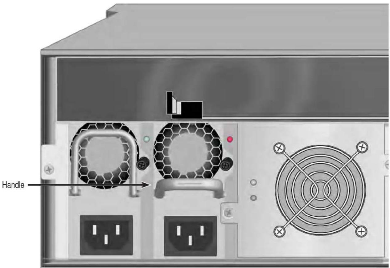
INSTALLING A NEW POWER SUPPLYT
To install the power supply:
- Carefully slide the power supply into the enclosure.
- Turn the set screw clockwise to tighten, DO NOT over tighten.
- Plug in the power cord.
-
Switch on the power supply.
-
Verify that the new power supply LED is green. See Power supply for Vess R26000
Insert fresh PSU

natural_image
Diagram of a computer power supply unit showing front panel, rear panels with fans and buttons, and a close-up view of the front panel (no text or symbols present)REPLACING A COOLING UNIT
A failed Cooling Unit on the Vess R2600 or Vess J2600 can be hot swapped if the other cooling unit is functioning properly (indicated by a green Fan Status LED). Follow the instructions below to replace a problem Cooling Unit.

Important
In the event of a Cooling Unit failure, DO NOT remove the failed unit until there is a replacement available and on hand. A single functioning Cooling Unit is adequate for cooling the system as long as the failed Cooling Unit remains in place. Removing the failed unit without replacing it will adversely affect airflow within the enclosure resulting in critical overheating and shutdown of the enclosure.
To remove the Cooling Unit
- Check the Fan Status LED, a red LED indicates the fan has failed and needs to be replaced, an amber LED indicates a problem. See "Cooling Unit LED indicates a problem with the fan" on page 543
- Use a No. 1 Phillips screwdriver to turn each set screw counter-clockwise to loosen them. The screws remain attached to the Cooling Unit so they will not be lost.
- Pull the detached Cooling Unit out of the subsystem enclosure. You can grasp the posts that house the set screws initially to move the unit out.
To insert a new Cooling Unit
- Align the fresh Cooling Unit to be received in the empty cooling unit bay of the subsystem enclosure.
- Slide the Cooling Unit into place until the set screws are able to be reattached to the backplane of the enclosure.
- Turn the set screws to tighten them.
- Check the Fan Status LED on the Cooling Unit to make sure it is green (functioning properly).
Cooling Unit LED indicates a problem with the fan

REPLACING A CACHE BACKUP BATTERY
The cache backup battery, also called a Battery Backup Unit (BBU) powers the cache to preserve data that has not been written the physical drives. The battery is attached to the top of the Cooling Unit assembly. Each Cooling unit has one battery. An amber or red BBU LED indicates a cache backup battery problem. See "Cooling Unit LED indicates a problem with the fan" on page 543.
To replace a backup battery, swap out the Cooling Unit with the BBU that needs replacement. Follow the instructions in "Replacing a Cooling Unit" on page 542.

Important
DO NOT remove a Cooling Unit unless there is a replacement available and on hand. Removing a single Cooling Unit without replacing it right away will adversely affect airflow within the enclosure resulting in critical overheating and shutdown of the enclosure.
Cooling Unit with Cache Backup Battery (BBU) LED indicating battery failure


Cautions
Try reconditioning the battery before you replace it. See "Reconditioning a Battery" on page 121.
The battery assembly is replaced as a unit. Do not attempt to disconnect the battery by itself.
Installing the wrong replacement battery can result in an explosion.
Dispose of used batteries according to the instructions that accompany the battery.
While the battery is removed, your system is vulnerable to data loss if the power fails while data is being written to the logical drives.
If power service has failed, do not remove the battery if the RAID controller's dirty cache LED is flashing. See "Rear Panel LEDs" on page 21.
REPLACING A RAID CONTROLLER – DUAL CONTROLLERS
The RAID controller monitors and manages the logical drives. When the RAID controller is replaced, all of your logical drive data and configurations remain intact because logical drive information is stored on the physical drives.

Important
Do not replace the RAID controller based on LED colors alone. Only replace the RAID controller when directed to do so by PROMISE Technical Support.
The firmware version and amount of SDRAM must be the same on the replacement RAID controller and the other RAID controller in the subsystem.
To obtain firmware and SDRAM information for an installed RAID controller, in WebPAM PROe, click the Administration button then click the Image Version icon.
Replacement RAID controllers to not come with a BBU. Remove the BBU from the old controller and install it into the new one. See .

Note
On subsystems with dual RAID controllers, you can hot-swap a controller while the subsystem is running.
- Disconnect all attached cables from the RAID controller,
- Fibre Channel cables
• Management port cables
- iSCSI cables
- Serial cable
- SAS expansion cables
- UPS control cable
- On the controller handle, squeeze the release tab and pull the handle outward.
RAID controller release handle and pull out

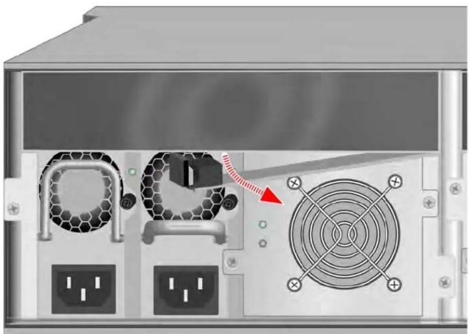
natural_image
Internal view of a server rack with ventilation fans and power outlets, showing no text or symbolsPull handle out, then slide controller unit straight out
- Pull the RAID controller out of the subsystem enclosure.
INSTALLING THE NEW CONTROLLER
To install the new RAID controller:
- Carefully slide the RAID controller into the enclosure.
- Gently swing the handle in and press the handle until it locks.
- Reconnect all cables that were attached to the RAID controller.
- Fibre Channel cables
- Management port cables
- iSCSI cables
- Serial cable
- SAS expansion cables
- UPS control cable
If one of the controllers goes into maintenance mode, see “RAID Controller Problems” and “Maintenance Mode” on page 627
REPLACING A RAID CONTROLLER – SINGLE CONTROLLER
The RAID controller monitors and manages the logical drives. When the RAID controller is replaced, all of your logical drive data and configurations remain intact because logical drive information is stored on the physical drives.

Cautions
The RAID controller is NOT hot-swappable if your Vess R2600 has only one controller. Power-down the Vess R2600 before removing it.

Important
Do not replace the RAID controller based on LED colors alone. Only replace the RAID controller when directed to do so by PROMISE Technical Support. See page 435.

Important
The firmware on the replacement RAID controller must be the same version as the original RAID controller or a later version.
The amount of SDRAM in the replacement RAID controller must be the same as the original RAID controller or greater.
To obtain firmware and SDRAM information for the currently installed RAID controller, click the Administration button then click the Image Version icon.
- Shutdown the Vess R2600.
- Disconnect all attached cables from the RAID controller,
- Fibre Channel cables
• Management port cables
- iSCSI cables
- Serial cable
- SAS expansion cables
- UPS control cable
-
On the controller handle, squeeze the release tab and pull the handle outward. See "RAID controller release handle and pull out" on page 546.
-
Pull the RAID controller out of the subsystem enclosure.
INSTALLING THE NEW CONTROLLER
To install the new RAID controller:
- Carefully slide the RAID controller into the enclosure.
- Gently swing the handle in and press the handle until it locks.
- Reconnect all cables that were attached to the RAID controller.
- Fibre Channel cables
- Management port cables
- iSCSI cables
- Serial cable
- SAS expansion cables
- UPS control cable
- Press the power power.
The Vess R2600 restarts.
- Log into the Vess R2600.
TECHNOLOGY BACKGROUND
This chapter covers the following topics:
- "Disk Arrays" (see below)
• "Logical Drives" on page 552 - "Spare Drives" on page 581
• "RAID Controllers" on page 588 - "iSCSI Management" on page 594
• "Internet Protocols" on page 602
Disk Arrays
Disk array technology includes:
- "Media Patrol"
• "PDM"
MEDIA PATROL
Media Patrol is a routine maintenance procedure that checks the magnetic media on each disk drive. Media Patrol checks all physical drives assigned to disk arrays and spare drives. Media Patrol does not check unconfigured drives.
Media Patrol checks are enabled by default on all disk arrays and spare drives. You can disable Media Patrol in the disk array and spare drive settings, however that action is not recommended.
Unlike Synchronization and Redundancy Check, Media Patrol is concerned with the condition of the media itself, not the data recorded on the media. If Media Patrol encounters a critical error, it triggers PDM, if PDM is enabled on the disk array.
Media Patrol has three status conditions:
- Running – Normal. You can access your logical drives at any time.
- Yield – Temporary pause while a read/write operation takes place.
- Paused – Temporary pause while another background runs. Or a pause initiated by the user.
PDM
Predictive Data Migration (PDM) is the migration of data from the suspect phy-cal drive to a spare drive, similar to rebuilding a logical drive. But unlike Re-building, PDM constantly monitors your physical drives and automatically copies your data to a spare drive before the physical drive fails and your logical drive goes Critical.
The following actions trigger PDM:
• A physical drive with unhealthy status (see below)
• Media Patrol finds a critical error
• You initiate PDM manually
PDM also counts the number of media errors reported by Media Patrol. A disk drive becomes unhealthy when:
• A SMART error is reported
- The bad sector remapping table fills to the specified level.
Because data would be lost if written to a bad sector, when a bad sector is detected, the physical drive creates a map around it. These maps are saved in the bad sector remapping table, which has a capacity of 512 reassigned blocks and 2048 error blocks. See “Making PDM Settings” on page 155 or “Managing Background Activities” on page 144.
You can specify the maximum levels for the reassigned and error blocks in PDM settings. When the table fills to a specified value, PDM triggers a migration of data from the suspect drive (the disk drive with the bad sectors) to a replacement physical drive.
During data migration, you have access to your logical drives but they respond more slowly to read/write tasks because of the additional operation. The time required for data migration depends on the size of the physical drives.
PDM is enabled on all disk arrays by default. You can disable PDM in the disk array settings, however that action is not recommended. See “Running PDM on a Disk Array” on page 195.
LOGICAL DRIVES
Logical drive technology includes:
- "RAID Levels" on page 553
• "RAID Level Migration" on page 570 - "Stripe Size" on page 579
• "Sector Size" on page 579 - "Preferred Controller ID" on page 579
- "Initialization" on page 580
• "Partition and Format" on page 580
RAID LEVELS
RAID (Redundant Array of Independent Disks) allows multiple physical drives to be combined together in a disk array. Then all or a portion of the disk array is formed into a logical drive. The operating system sees the logical drive as a single storage device, and treats it as such.
RAID 0 - STRIPE
When a logical drive is striped, the read and write blocks of data are interleaved between the sectors of multiple physical drives. Performance is increased, since the workload is balanced between drives or “members” that form the logical drive. Identical drives are recommended for performance as well as data storage efficiency.
RAID 0 Striping interleaves data across multiple drives
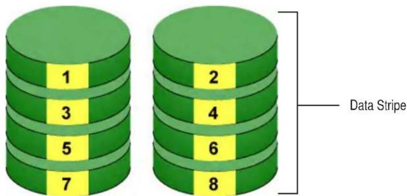
Physical Drives
The disk array's data capacity is equal to the number of disk drive members multiplied by the smallest drive's capacity. For example, one 100 GB and three 120 GB drives form a 400 GB (4 x 100 GB) disk array instead of 460 GB.
If physical drives of different capacities are used, there is unused capacity on the larger drives. RAID 0 logical drives on Vess consist of one or more physical drives.
| Advantages Disadvantages | |
| • Implements a striped disk array, the data is broken down into blocks and each block is written to a separate disk drive• I/O performance is greatly improved by spreading the I/O load across many channels and drives• No parity calculation overhead is involved | • Not a true RAID because it is not fault-tolerant• The failure of just one drive results in all data in an disk array being lost• Should not be used in mission critical environments |
Recommended Applications for RAID 0:
- Image Editing
• Pre-Press Applications
• Any application requiring high
RAID 1 - MIRROR
When a logical drive is mirrored, identical data is written to a pair of physical drives, while reads are performed in parallel. The reads are performed using elevator seek and load balancing techniques where the workload is distributed in the most efficient manner. Whichever drive is not busy and is positioned closer to the data is accessed first.
With RAID 1, if one physical drive fails or has errors, the other mirrored physical drive continues to function. Moreover, if a spare physical drive is present, the spare drive is used as the replacement drive and data begins to mirrored to it from the remaining good drive.
RAID 1 Mirrors identical data to two drives

Physical Drives
The logical drive's data capacity equals the smaller physical drive. For example, a 100 GB physical drive and a 120 GB physical drive have a combined capacity of 100 GB in a mirrored logical drive.
If physical drives of different capacities are used, there is unused capacity on the larger drive.
RAID 1 logical drives on Vess consist of two physical drives.
If you want a mirrored logical drive with more than two physical drives, see "RAID 1E – Enhanced Mirror" on page 557.
| Advantages Disadvantages | |
| Simplest RAID storage subsystem designCan increase read performance by processing data requests in parallel since the same data re-sides on two different drives | Very high disk overhead – uses only 50% of total capacity |
Recommended Applications for RAID 1:
- Accounting
- Payroll
- Financial
• Any application requiring very high availability
RAID 1E - ENHANCED MIRROR
RAID 1E offers the security of mirrored data provided by RAID 1 plus the added capacity of more than two physical drives. It also offers overall increased read/write performance plus the flexibility of using an odd number of physical drives. With RAID 1E, each data stripe is mirrored onto two physical drives. If one drive fails or has errors, the other drives continue to function, providing fault tolerance.
RAID 1E can mirror data over an odd number of drives

The advantage of RAID 1E is the ability to use an odd number of physical drives, unlike RAID 1 and RAID 10. You can also create a RAID 1E Logical Drive with an even number of physical drives. However, with an even number of drives, you obtain somewhat greater security with comparable performance using RAID 10.
RAID 1E logical drives consist of three or more physical drives. You can create an array with just two physical drives and specify RAID 1E. But the resulting ar-ray is actually a RAID 1.
| Advantages Disadvantages | |
| Implemented as a mirrored disk array whose segments are RAID 0 disk arraysHigh I/O rates are achieved thanks to multiple stripe seg-mentsCan use an odd number of disks | Very high disk overhead – uses only 50% of total capacity |
Recommended Applications for RAID 1E:
- Imaging applications
- Database servers
- General fileserver
RAID 5 - BLOCK AND PARITY STRIPE
RAID 5 organizes block data and parity data across the physical drives. Gener-ally, RAID Level 5 tends to exhibit lower random write performance due to the heavy workload of parity recalculation for each I/O. RAID 5 is generally considered to be the most versatile RAID level. It works well for file, database, application and web servers.
RAID 5 stripes all drives with data and parity information
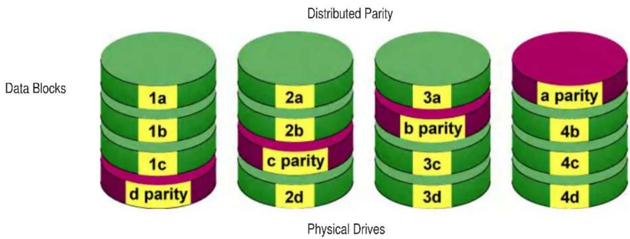
The capacity of a RAID 5 logical drive equals the smallest physical drive times the number of physical drives, minus one. Hence, a RAID 5 logical drive with four 100 GB physical drives has a capacity of 300 GB. A RAID 5 logical drive with two 120 GB physical drives and one 100 GB physical drive has a capacity of 200 GB.
RAID 5 is generally considered to be the most versatile RAID level.
A RAID 5 on Vess consists of 3 to 32 physical drives.
Recommended Applications for RAID 5:
| Advantages Disadvantages | |
| ·High Read data transaction rate·Medium Write data transaction rate·Good aggregate transfer rate·Most versatile RAID level | ·Disk failure has a medium impact on throughput |
• File and Application servers
• WWW, E-mail, and News servers
- Intranet servers
RAID 6 - BLOCK AND DOUBLE PARITY STRIPE
RAID level 6 stores dual parity data is rotated across the physical drives along with the block data. A RAID 6 logical drive can continue to accept I/O requests when any two physical drives fail.
Hence, a RAID 6 logical drive with (7) 100 GB physical drives has a capacity of 500 GB. A RAID 6 logical drive
RAID 6 stripes all drives with data and dual parity

with (4) 100 GB physical drives has a capacity of 200 GB.
RAID 6 becomes more capacity efficient in terms of physical drives as the number of physical drives increases.
RAID 6 provides double fault tolerance. Your logical drive remains available when up to two physical drives fail.
RAID 6 is generally considered to be the safest RAID level.
A RAID 6 on Vess consists of 4 to 32 physical drives.
| Advantages Disadvantages | |
| High Read data transaction rateMedium Write data transaction rateGood aggregate transfer rateSafest RAID level, except for RAID 60 | High disk overhead – equivalent of two drives used for paritySlightly lower performance than RAID 5 |
Recommended Applications for RAID 6:
• Accounting and Financial
- Database servers
• Any application requiring very high availability
RAID 10 - MIRROR + STRIPE
Mirror + Stripe combines both of the RAID 1 and RAID 0 logical drive types. RAID 10 can increase performance by reading and writing data in parallel or striping, and duplicating the data, or mirroring.
PROMISE implements RAID 10 by creating a data stripe over one pair of disk drives, then mirroring the stripe over a second pair of disk drives. Some applications refer to this method as RAID 0+1.
PROMISE RAID 10 starts with a data stripe, then mirrors it

The data capacity RAID 10 logical drive equals the capacity of the smallest physical drive times the number of physical drives, divided by two.
In some cases, RAID 10 offers double fault tolerance, depending on which physical drives fail.
RAID 10 arrays require an even number of physical drives and a minimum of four.
For RAID 10 characteristics using an odd number of physical drives, choose RAID 1E.
| Advantages Disadvantages | |
| Implemented as a mirrored disk array whose segments are RAID 0 disk arraysHigh I/O rates are achieved thanks to multiple stripe segments | Very high disk overhead – uses only 50% of total capacity |
Recommended Applications for RAID 10:
- Imaging applications
- Database servers
- General fileserver
RAID 50 - STRIPING OF DISTRIBUTED PARITY
RAID 50 combines both RAID 5 and RAID 0 features. Data is striped across physical drives as in RAID 0, and it uses distributed parity as in RAID 5. RAID 50 provides data reliability, good overall performance, and supports larger volume sizes.
RAID 50 is a combination of RAID 5 and RAID 0
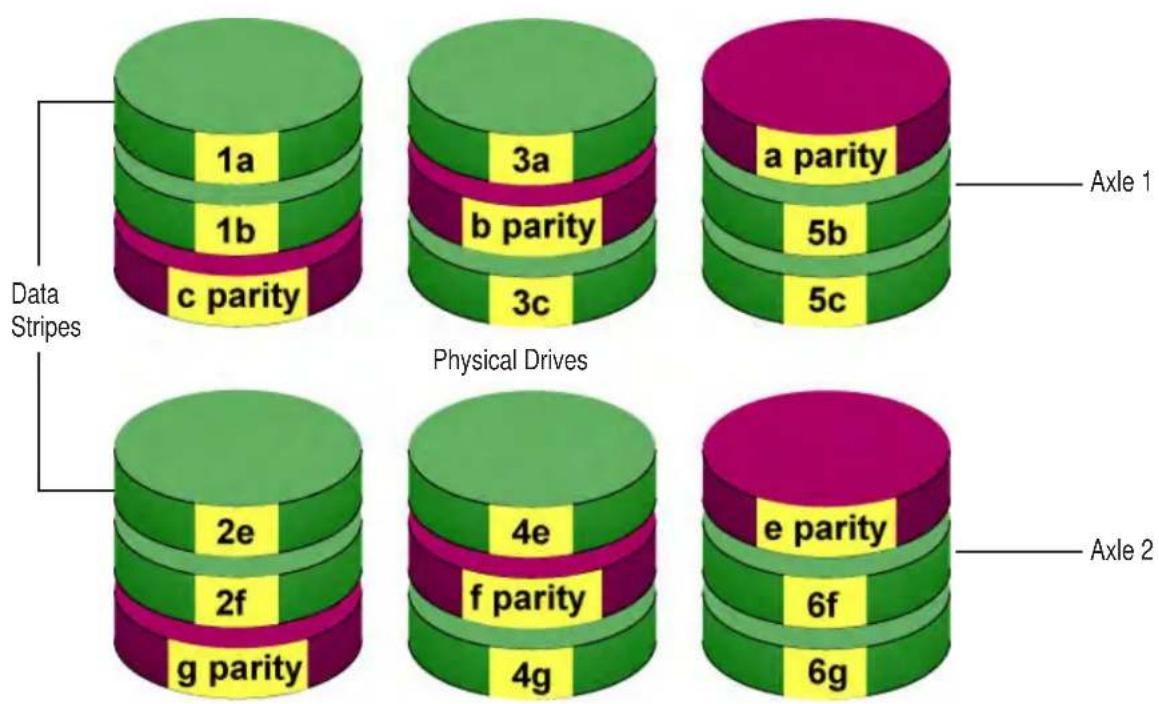
| Advantages Disadvantages | |
| ·High Read data transaction rate·Medium Write data transaction rate·Good aggregate transfer rate·High reliability·Supports large volume sizes | ·Higher disk overhead than RAID 5 |
Recommended Applications for RAID 50:
• File and Application servers
• Transaction processing
• Office application with many users accessing small files
The data capacity RAID 50 logical drive equals the capacity of the smallest physical drive times the number of physical drives, minus two.
RAID 50 also provides very high reliability because data is still available even if multiple physical drives fail (one in each axle). The greater the number of axles, the greater the number of physical drives that can fail without the RAID 50 logical drive going offline.
| Components Minimum Maximum | ||
| Number of Axles | 2 16 | |
| Physical Drives per Axle | 3 32 | |
| Physical Drives per Logical Drive | 6 256 | |
RAID 50 Axles
When you create a RAID 50, you must specify the number of axles. An axle re-fers to a single RAID 5 logical drive that is striped with other RAID 5 logical drives to make RAID 50. An axle can have from 3 to 32 physical drives, de-pending on the number of physical drives in the logical drive.
The chart below shows RAID 50 logical drives with 6 to 32 physical drives, the available number of axles, and the resulting distribution of physical drives on each axle.
RAID 50 Logical Drive
| Drives Axles | Drives/ Axle | |
| 6 2 3,3 | ||
| 7 2 3,4 | ||
| 8 2 4,4 | ||
| 9 | 2 4,5 | |
| 3 3,3,3 | ||
| 10 | 2 5,5 | |
| 3 3,3,4 | ||
| 11 | 2 5,5 | |
| 3 3,3,4 | ||
| 12 | 2 6,6 | |
| 3 4,4,4 | ||
| 4 3,3,3,3 | ||
| 13 | 2 6,7 | |
| 3 4,4,5 | ||
| 4 3,3,3,4 | ||
| 14 | 2 7,7 | |
| 3 4,5,5 | ||
| 4 3,3,4,4 | ||
| 15 | 2 7,8 | |
| 3 5,5,5 | ||
| 4 3,4,4,4 | ||
| 5 3,3,3,3,3 | ||
| 16 | 2 8,8 | |
| 3 5,5,6 | ||
| 4 4,4,4,4 | ||
| 5 3,3,3,3,4 |
RAID 60 - STRIPING OF DOUBLE PARITY
RAID 60 combines both RAID 6 and RAID 0 features. Data is striped across disks as in RAID 0, and it uses double distributed parity as in RAID 6. RAID 60 provides data reliability, good overall performance and supports larger volume sizes.
RAID 60 is a combination of RAID 6 and RAID 0

The total capacity of a RAID 60 logical drive is the smallest physical drive times the number of physical drives, minus four.
RAID 60 also provides very high reliability because data is still available even if multiple physical drives fail (two in each axle). The greater the number of axles, the greater the number of physical drives that can fail without the RAID 60 logical drive going offline.
| Advantages Disadvantages | |
| High Read data transaction rateMedium Write data transaction rateGood aggregate transfer rateSafest RAID level | High disk overhead – equivalent of two drives used for paritySlightly lower performance than RAID 50 |
Recommended Applications for RAID 60:
• Accounting and Financial
- Database servers
• Any application requiring very high availability
| Components Minimum Maximum | ||
| Number of Axles 2 | 16 | |
| Physical Drives per Axle 4 | 32 | |
| Physical Drives per Logical Drive 8 | 256 | |
RAID 60 Axles
When you create a RAID 60, you must specify the number of axles. An axle refers to a single RAID 6 logical drive that is striped with other RAID 6 logical drives to make RAID 60. An axle can have from 4 to 32 physical drives, de-pending on the number of physical drives in the logical drive.
RAID 60 Logical Drive
| Drives Axles | Drives/ Axle | |
| 8 2 4,4 | ||
| 9 2 4,5 | ||
| 10 2 4,5 | ||
| 11 2 5,6 | ||
| 12 | 2 6,6 | |
| 3 4,4,4 | ||
| 13 | 2 6,7 | |
| 3 4,4,5 | ||
| 14 | 2 7,7 | |
| 3 4,5,5 | ||
| 15 | 2 7,8 | |
| 3 5,5,5 | ||
| 16 | 2 8,8 | |
| 3 5,5,6 | ||
| 4 4,4,4,4 | ||
| 17 | 2 8,9 | |
| 3 5,6,6 | ||
| 4 4,4,4,5 | ||
| 18 | 2 9,9 | |
| 3 6,6,6 | ||
| 4 4,4,5,5 | ||
| 19 | 2 9,10 | |
| 3 6,6,7 | ||
| 4 4,5,5,5 | ||
| 20 | 2 10,10 | |
| 3 6,6,7 | ||
| 4 5,5,5,5 | ||
| 5 4,4,4,4,4 |
RAID LEVEL MIGRATION
The term "Migration" means either or both of the following:
- Change the RAID level of a logical drive.
- Expand the storage capacity of a logical drive.
On Vess, RAID level migration is performed on the disk array but it applies to the logical drives. Migration does not disturb your data. You can access the data while the migration is in progress. When migration is done, your disk array has a different RAID level and/or a larger capacity.
MIGRATION REQUIREMENTS
The following conditions affect RAID level migration:
- The disk array and logical drive must show a green check icon.
- The Target disk array may require more physical drives than the Source disk array.
- If the Target disk array requires an EVEN number of physical drives but the Source disk array has an ODD number, ADD a physical drive as part of the migration process.
- You cannot reduce the number of physical drives in your disk array, even if the Target disk array requires fewer physical drives than the Source disk array.
- RAID 1 (mirroring) works with two drives only. Only a single-drive RAID 0 disk array can migrate to RAID 1. Other RAID Levels use too many drives to migrate.
- You cannot migrate a disk array when it is Critical or performing activities such as Synchronizing, Rebuilding, and PDM.
- For RAID 6 or RAID 60, you can only migrate between these two RAID le-vels. Destination RAID 60 axles can have up to 16 physical drives. Other limitations might apply.
SOURCE AND TARGET RAID LEVELS
The tables on the following pages show the migration options for each source logical drive by its RAID level. The available target RAID levels are shown with their requirements.
RAID 0
A RAID 0 source logical drive can migrate to the following target logical drives:
| Target | Requirements |
| RAID 0 | Add physical drives. |
| RAID 1 | 2 physical drives only.Only a single-drive RAID 0 can migrate to RAID 1 by adding 1 physical drive. |
| RAID 1E | 3 or more physical drives. If existing physical drives have no unused space, add 1 or more physical drives. |
| RAID 5 | 3 physical drives minimum, 32 maximum.RAID 0 must have less than 16 physical drives.If existing physical drives have no unused space, add 1 or more physical drives. |
| RAID 6 | 4 physical drives minimum, 32 maximum.If existing physical drives have no unused space, add 1 or more physical drives. |
| RAID 10 | 4 physical drives minimum.Even number of physical drives.If existing physical drives have no unused space, add 1 or more physical drives. |
| RAID 50 | 6 physical drives minimum, 32 per axle maximum.If existing physical drives have no unused space, add 1 or more physical drives. |
| RAID 60 | 8 physical drives minimum, 32 per axle maximum.If existing physical drives have no unused space, add 1 or more physical drives. |
RAID 1
A RAID 1 source logical drive can migrate to the following target logical drives:
| Target | Requirements |
| RAID 0 | None. |
| RAID 1E | 3 or more physical drives.Add 1 or more physical drives. |
| RAID 5 | 3 physical drives minimum, 32 maximum.RAID 1 must have less than 32 physical drives.Add 1 or more physical drives. |
| RAID 10 | 4 physical drives minimum.Even number of physical drives.Add 2 or more physical drives. |
| RAID 50 | 6 physical drives minimum, 32 per axle maximum.Add 4 or more physical drives. |
RAID 1E
A RAID 1E source logical drive can migrate to the following target logical drives:
| Target | Requirements |
| RAID 0 None. | |
| RAID 1E | Add physical drives. |
| RAID 5 | 3 physical drives minimum, 32 maximum.RAID 1E must have less than 32 physical drives.If existing physical drives have no unused space, add 1 or more physical drives. |
| RAID 10 | 4 physical drives minimum.Even number of physical drives.If existing physical drives have no unused space, add 1 or more physical drives. |
| RAID 50 | 6 physical drives minimum, 32 per axle maximum. |
RAID 5
A RAID 5 source logical drive can migrate to the following target logical drives:
| TargetRequirements | |
| RAID 0 None. | |
| RAID 1E None. | |
| RAID 5 | Add physical drives. 32 maximum. |
| RAID 6 | 4 physical drives minimum, 32 maximum.If existing physical drives have no unused space, add 1 or more physical drives. |
| RAID 10 | 4 physical drives minimum.Even number of physical drives.If existing physical drives have no unused space, add 1 or more physical drives. |
| RAID 50 | 6 physical drives minimum, 32 per axle maximum.If existing physical drives have no unused space, add 1 or more physical drives. |
| RAID 60 | 8 physical drives minimum, 32 per axle maximum.If existing physical drives have no unused space, add 1 or more physical drives. |
RAID 6
A RAID 6 source logical drive can migrate to the following target logical drives:
| Target | Requirements |
| RAID 6 | Add physical drives. 32 maximum. |
| RAID 60 | 8 physical drives minimum, 32 per axle maximum.If existing physical drives have no unused space, add 1 or more physical drives. |
RAID 10
A RAID 10 source logical drive can migrate to the following target logical drives:
| Target | Requirements |
| RAID 0 | None. |
| RAID 1 | None. |
| RAID 5 | 3 physical drives minimum, 32 maximum.RAID 10 must have less than 16 physical drives. |
| RAID 6 | 4 physical drives minimum, 32 maximum.RAID 10 must have less than 32 physical drives.If existing physical drives have no unused space, add 1 or more physical drives. |
| RAID 10 | Add physical drives.Even number of physical drives. |
| RAID 50 6 | physical drives minimum, 32 per axle maximum. |
| RAID 60 | 8 physical drives minimum, 32 per axle maximum.If existing physical drives have no unused space, add 1 or more physical drives. |
When you migrate RAID 10 logical drive, it becomes RAID 1E by default.
If you want a RAID 10 logical drive, there must be an even number of physical drives and you must specify RAID 10 for the target logical drive.
RAID 50
A RAID 50 source logical drive can migrate to the following target logical drives:
| Target | Requirements |
| RAID 0 | None. |
| RAID 1E | None. |
| RAID 5 | 32 physical drives maximum. |
| RAID 6 | 32 physical drives maximum.RAID 50 must have less than 32 physical drives.If existing physical drives have no unused space, add 1 or more physical drives. |
| RAID 10 | Even number of physical drives. |
| RAID 50 | Add physical drives. 32 per axle maximum. |
| RAID 60 | 8 physical drives minimum, 32 per axle maximum.If existing physical drives have no unused space, add 1 or more physical drives. |
You can add physical drives to a RAID 50 array but you cannot change the number of axles.
RAID 60
A RAID 60 source logical drive can migrate to the following target logical drives:
| Target | Requirements |
| RAID 6 | 32 physical drives maximum.RAID 60 must have less than 32 physical drives.If existing physical drives have no unused space, add 1 or more physical drives. |
| RAID 60 | Add physical drives. 32 per axle maximum. |
You can add physical drives to a RAID 60 array but you cannot change the number of axles.
STRIPE SIZE
Stripe Size, also called “Stripe Block Size,” refers to the size of the data blocks written to, and read from, the physical drives. Stripe Size is specified when you create a logical drive. You can choose Stripe Size directly when you use the Wizard Advanced Configuration function to create a logical drive.
You cannot change the Stripe Size of an existing logical drive. You must delete the logical drive and create a new one.
The available Stripe Sizes are 64 KB, 128 KB, 256 KB, 512 KB, and 1 MB. 64 KB is the default. There are two issues to consider when choosing the Stripe Size:
- You should choose a Stripe Size equal to, or smaller than, the smallest cache buffer found on any physical drive in the disk array. Selecting a larger value slows read/write performance because physical drives with smaller cache buffers need more time for multiple accesses to fill their buffers.
- If your data retrieval consists of fixed data blocks, such as with some data-base or video applications, then you should choose that size as your Stripe Size.
- If you do not know the cache buffer or fixed data block sizes, choose 64 KB as your Stripe Size. Generally speaking,
- Email, POS, and web servers prefer smaller stripe sizes.
• Video and database applications prefer larger stripe sizes.
SECTOR SIZE
A sector is the smallest addressable area on a physical drive. Sector size refers to the number of data bytes a sector can hold. A smaller sector size is a more efficient use of a physical drive's capacity. 512 bytes (512 B) is the most common sector size, and the default in WebPAM PROe.
PREFERRED CONTROLLER ID
When you create a logical drive using the Advanced method of disk array creation, you can specify the Preferred Controller ID:
- Controller 1 – Assign all logical drives to Controller 1
- Controller 2 – Assign all logical drives to Controller 2.
• Automatic – Alternate logical drive assignments between Controllers 1 and 2.
Automatic is the default and preferred setting because it balances the logical drive assignments for you.
See “Creating a Disk Array Manually” on page 190, “Creating a Disk Array with the Wizard” on page 191, and “Advanced Configuration” on page 87.
INITIALIZATION
Initialization is done to logical drives after they are created from a disk array. Full initialization sets all data bits in the logical drive to a specified pattern, such as all zeros. The action is useful because there may be residual data on the logical drives left behind from earlier configurations. For this reason, Initialization is recommended for all new logical drives. See “Initializing a Logical Drive” on page 207.

Caution
When you initialize a logical drive, all the data on the logical drive is lost. Backup any important data before you initialize a logical drive.
PARTITION AND FORMAT
Like any other type of fixed disk media in your system, a RAID logical drive must also be partitioned and formatted before use. Use the same method of partitioning and formatting on an logical drive as you would any other fixed disk.
Depending on the operating system you use, there may or may not be various capacity limitations applicable for the different types of partitions.
SPARE DRIVES
Spare drive technology includes:
- "Definition" (below)
- "Options" (below)
- "Requirements" on page 582
- "Transition" on page 582
DEFINITION
A spare drive is a physical drive that you designate to automatically replace the failed physical drive in a disk array. See “Creating a Spare Drive Manually” on page 215.
The general recommendation is to:
- Provide at least one spare drive for every 16 physical drives in the RAID system
- Configure the spares as global revertible spare drives
OPTIONS
There are several options you can specify for a spare drive:
- System Options
- Revertible – Returns to its spare drive assignment after you replace the failed physical drive in the disk array and run the Transition function.
• Media Patrol – By default, Media Patrol runs on spare drives unless you disable it. - Spare Type
- Global – Can be used by any disk array
• Dedicated – Can be used only by the assigned disk array
• Media Type (type of physical drive) - Hard Disk Drive (HDD)
• Solid State Drive (SSD)
REQUIREMENTS
The spare drive must:
- Have adequate capacity to replace the largest physical drive in your disk arrays.
- Be the same media type as the physical drives in your disk arrays.
• A revertible spare drive requires: - You to replace the failed physical drive in the disk array
• You to run the Transition function
TRANSITION
Transition is the process of replacing a revertible spare drive that is currently part of a disk array with an unconfigured physical drive or a non-revertible spare. The revertible spare drive returns to its original status. In order to run the Transition function, the spare drive must be revertible.
In addition, you must specify an unconfigured physical drive of the same or larger capacity and same media type as the revertible spare drive.
RUNNING A TRANSITION
The Transition feature enables you to specify “permanent” spare drives for your Vess subsystem. Transition is the process of replacing a revertible spare drive that is currently part of a disk array with an unconfigured physical drive or a non-revertible spare. The revertible spare drive returns to its original status.
Transition happens automatically when the following sequence of events takes place:
- You create a revertible spare drive. See “Creating a Spare Drive Manually” on page 215.
• A physical drive assigned to your disk array fails and the array goes critical or degraded. - Vess automatically rebuilds your array to the revertible spare drive and the array becomes functional again.
• You replace the failed physical drive with a new physical drive of equal or greater capacity. - Vess automatically transitions (moves) the data from the revertible spare to the new physical drive.
The new physical drive becomes part of the array and the reversible spare drive returns to its original spare status.
Transition happens manually when you specify a different unconfigured physical drive to transition (move) the data from the revertible spare drive.
See the example on the following pages.
Example
Following is an example to explain the Transition function.

In the example above, there is a four-drive RAID 5 disk array and a global spare drive. Physical drives 1, 2, 3, and 4 belong to the disk array. Physical drive 5 remains unconfigured. Physical drive 6 is a revertible spare drive.

bar
| Category | Value | |---|---| | 1 | Green Dot | | 2 | Green Dot | | 3 | Red Dot | | 4 | Green Dot | | 5 | Grey Dot | | 6 | Green Dot | | 1 | Blue Dot | | 2 | Blue Dot | | 3 | Blue Dot | | 4 | Blue Dot | | 5 | Blue Dot | | 6 | Blue Dot | The chart is divided into two sections: 'Failed Drive' (top) and 'Rebuild to Spare' (bottom). The top section contains a red dot labeled 'Failed Drive'. The bottom section contains a gray dot labeled 'Rebuild to Spare'.If a physical drive fails in a disk array and there is a spare drive of adequate capacity available, the controller automatically rebuilds the array using the spare drive. In this example, physical drive 3 failed and the array is rebuilt using physical drive 6, the revertible spare drive.

When the rebuild is complete, the spare drive has replaced the failed drive. In this example, failed drive 3 was replaced by spare drive 6. The disk array now consists of physical drives 1, 2, 4, and 6.
There is no spare drive at this moment. Even if physical drive 5 is of adequate capacity, it has not been designated as a spare, therefore the controller cannot use it as a spare.
Automatic Transition
At this juncture, you would replace the failed drive in slot 3 with a new one of the same or greater capacity.

flowchart
graph TD
    A["1"] --> B["Array Drives"]
    C["2"] --> D["Array Drives"]
    E["3"] --> F["Array Drives"]
    G["4"] --> H["Array Drives"]
    I["5"] --> J["Array Drives"]
    K["6"] --> L["Spare Drive"]
When the Vess controller detects the new drive in slot 3, the controller:
• Automatically transitions the data on drive 6 to drive 3
• Returns drive 6 to spare status
When the Automatic Transition is finished, physical drives 1, 2, 3, and 4 belong to the disk array and physical drive 6 is a revertible spare drive. The original configuration is restored.
Manual Transition
If you wanted to use the drive in slot 5 as a member of the disk array, rather than the drive in slot 3, you would run the Transition function manually. See “Running a Transition on a Spare Drive” on page 218.

flowchart
graph TD
    A["1"] --> B["Array Drives"]
    C["2"] --> D["Array Drives"]
    E["3"] --> F["Array Drives"]
    G["4"] --> H["Array Drives"]
    I["5"] --> J["Array Drives"]
    K["6"] --> L["Spare Drive"]
When the Manual Transition is finished, physical drives 1, 2, 4, and 5 belong to the disk array and physical drive 6 is a revertible spare drive.
At this point, you would replace the drive in slot 3. The new drive in slot 3 re-mains unconfigured until you assign it to a disk array or as a spare.
RAID CONTROLLERS
RAID controller technology includes;
- "LUN Affinity" (below)
- "ALUA" (below)
• "Cache Policy" on page 589 - "Read Cache Policy" on page 589
• "Write Cache Policy" on page 590
• "Power Saving" on page 592
• "Capacity Coercion" on page 592
LUN AFFINITY
Vess subsystems with dual RAID controllers include a LUN Affinity feature. Normally, either controller can access all logical drives. LUN Affinity enables you to specify which controller can access each logical drive. Use this feature to balance the load of your logical drives between the two controllers.
To use LUN Affinity you must:
• Have two RAID controllers in the subsystem.
- Set the redundancy type to Active-Active. See “Making Subsystem Settings” on page 102.
- Enable LUN Affinity. See "Making Controller Settings" on page 114.
On subsystems with two RAID controllers, when Cache Mirroring is disabled, LUN Affinity is enabled automatically.
ALUA
Vess supports Asymmetric Logical Unit Access (ALUA) on Linux OSes. ALUA is a multipathing tool. It enables an initiator (your host PC or server) to discover target port groups that provide a common failover / failback behavior for your LUNs. ALUA enables the host to see which paths are in an optimal state and which are not.
To use ALUA you must:
• Have two RAID controllers in the subsystem.
- Set the redundancy type to Active-Active. See "Making Subsystem Settings" on page 102.
- Enable LUN Affinity and ALUA. See “Making Controller Settings” on page 114.
CACHE POLICY
As it is used with Vess, the term cache refers to any of several kinds of high-speed, volatile memory that hold data moving from your computer to the physical drives or vice-versa. Cache is important because it can read and write data much faster than a physical drive. There are read caches, which hold data as it is read from a physical drive; and write caches, which hold data as it is written to a physical drive.
In order to tune the cache for best performance in different applications, user-adjustable settings are provided. Cache settings are made on the RAID controller. See “Making Controller Settings” on page 114.
READ CACHE POLICY
- Read Cache – The read cache is enabled but no pre-fetch action.
- Read Ahead – The read cache and predictive pre-fetch feature are enabled. Read-ahead anticipates the next read and performs it before the request is made. Can increase read performance.
- Forced Read Ahead – The read cache and aggressive pre-fetch feature are enabled. See “Forced Read-Ahead Cache” below.
- No Cache – The read cache is disabled.
WRITE CACHE POLICY
- Write Back – Data is written first to the cache, then to the logical drive. Better performance. Vess has a cache backup battery to protect data in the cache from a sudden power failure.
- Adaptive Writeback – See “Adaptive Writeback Cache” below.
- Write Thru – Also “Write Through.” Data is written to the cache and the logical drive at the same time. Safer.
If your write cache policy is set to Write Back, the write policy automatically changes to Write Thru when all of the following conditions occur:
• The logical drive write policy is set to Write Back
• The Adaptive Writeback Cache feature is enabled
• The cache backup battery goes offline
When the battery comes back online, the write policy automatically changes back to Write Back.
Also see "Viewing Battery Information" on page 120.
Forced Read-Ahead Cache
On the Vess subsystem, you can set the logical drive read cache policy to Forced Read Ahead an enable the aggressive pre-fetch feature.
The Forced Read-Ahead cache policy setting provides predictive pre-fetching of data requests, allowing the controller to aggressively buffer large chunks of data in cache memory to prevent frame drops on high-bandwidth video playback. Not normally enabled for non-video applications.
ADAPTIVE WRITEBACK CACHE
On the Vess subsystem, you can set the logical drive write cache policy to Write Thru or Write Back.
If you set the write cache policy to Write Back, your data is first written to the controller cache, and later to the logical drive. This action is conducted to improve performance. In order to preserve the data in the cache in the event of a power failure, the subsystem has a backup battery that provides continuous power to maintain the cache. To see an estimate of how long the battery can power the cache, see “Viewing Battery Information” on page 120.
The Adaptive Writeback Cache feature protects your data by changing the write cache settings while the cache backup battery is offline. When all of the following conditions occur:
• The logical drive write policy is set to Write Back.
• The Adaptive Writeback Cache feature is enabled.
- The cache backup battery goes offline. (See definition in Note below)
The write policy automatically changes to Write Thru. When the battery comes back online, the write policy automatically changes back to Write Back.
To enable the Adaptive Writeback Cache option, see "Making Controller Settings" on page 114.

natural_image
Simple icon of a yellow pencil inside a square frame (no text or symbols)Notes
The condition "cache battery goes offline" can be due to one of the following circumstances:
- Battery not installed.
- Battery remaining capacity is not enough to keep data, outcome depends if
Advanced Battery Flash Backup is enabled or disabled:
◇ Advanced Battery Flash Backup disabled:
* less than 72hrs (48hrs for 16GB of memory).
* [Check battery info: EstimateHoldTime field.]
◇ Advanced Battery Flash Backup enabled:
* less than 3 times backup cycle.
* [Check battery info: EstimateBackupCycle field.]
Host Cache Flushing
On the Vess subsystem, you can enable or disable host cache flushing.
When enabled, host cache flushing guards against data loss in the event of a power failure. However RAID performance is slightly reduced.
When disabled, the Vess subsystem has greater sustained bandwidth and lower latency, which are helpful for real-time video capture.
When you operate the Vess with host cache flushing disabled, use a UPS to protect against data loss.
Preferred Controller ID
See "Preferred Controller ID" on page 579.
POWER SAVING
Power saving is a method of conserving energy by applying specific actions to hard disk drives (HDD). After an HDD has been idle for the set period of time, you can elect to:
- Park the read/write heads – Referred to as Power Saving Idle Time on Vess.
- Reduce disk rotation speed – Referred to as Power Saving Standby Time on Vess.
- Spin down the disk (stop rotation) – Referred to as Power Saving Stopped Time on Vess.
Power management must be:
- Set on the RAID controller. See "Making Controller Settings" on page 114.
- Enabled on each HDD. See "Making Disk Array Settings" on page 193.
CAPACITY COERCION
This feature is designed for fault-tolerant logical drives (RAID 1, 1E, 5, 10, 50, and 60). It is generally recommended to use physical drives of the same size in your disk arrays. When this is not possible, the system adjusts for the size differences by reducing or coercing the capacity of the larger drives to match the smaller ones. With Vess, you can choose to enable capacity coercion and any one of four methods.
Enable capacity coercion and choose a method, see See "Making Controller Settings" on page 114.
- GB Truncate – (Default) Reduces the useful capacity to the nearest 1,000,000,000 byte boundary.
- 10GB Truncate – Reduces the useful capacity to the nearest 10,000,000,000 byte boundary.
- Group Rounding – Uses an algorithm to determine how much to truncate. Results in the maximum amount of usable drive capacity.
- Table Rounding – Applies a predefined table to determine how much to truncate.
Capacity coercion also affects a replacement drive used in a disk array. Normally, when an physical drive fails, the replacement drive must be the same capacity or larger. However, the capacity coercion feature permits the installation of a replacement drive that is slightly smaller (within 1 gigabyte) than the remaining working drive. For example, the remaining working drives can be 80.5 GB and the replacement drive can be 80.3, since all are rounded down to 80 GB. This permits the smaller drive to be used.
Without capacity coercion, the controller does not permit the use of a replacement physical drive that is slightly smaller than the remaining working drives.
ISCSI MANAGEMENT
iSCSI management uses the following terms:
- "Basic iSCSI" (below)
- "iSCSI on a VLAN" on page 596
- "Initiator" on page 598
- "Target" on page 598
- "Portal" on page 599
- "Port" on page 600
- "Trunk" on page 600
- "Session" on page 600
- "iSNS" on page 601
- "CHAP" on page 601
- "Ping" on page 601
Also see "Managing iSCSI Connections" on page 232.
A detailed explanation of iSCSI functions and how to best use them is beyond the scope of this document. For more information, contact the Internet Engineering Task Force at http://www.ietf.org/
BASIC ISCSI
See the diagram below.
To set up the data connections on a Vess iSCSI subsystem:
- Add a new portal. See "Adding iSCSI Portals" on page 237.
Note which iSCSI port you chose for the portal.. - Assign the new portal to the target.
- Map the target to a LUN. See "Adding a LUN Map" on page 224.
Connect your iSCSI data cable to the iSCSI port you chose for the new portal.
See "iSCSI Storage Area Network (SAN)" on page 51. - Add your iSCSI initiators to the Vess's initiator list.
See "Adding an iSCSI Initiator" on page 222.
For more information, see:
- "Managing iSCSI Connections" on page 232.
- Visit the Promise Knowledgebase at http://kb.promise.com/ and access topic "10188 – Setting up Microsoft iSCSI Initiator With the Vess"
iSCSI component map
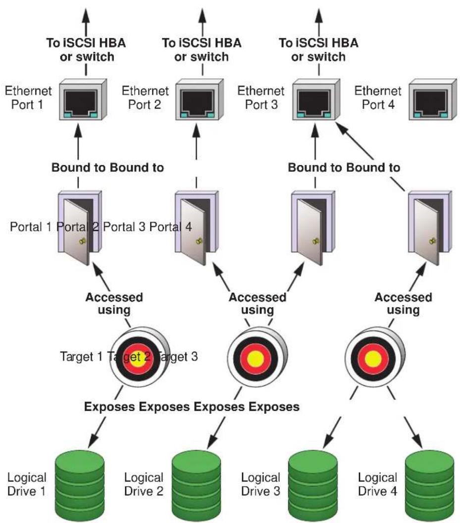
flowchart
graph TD
    A["To iSCSI HBA or switch"] --> B["Ethernet Port 1"]
    C["To iSCSI HBA or switch"] --> D["Ethernet Port 2"]
    E["To iSCSI HBA or switch"] --> F["Ethernet Port 3"]
    G["To iSCSI HBA or switch"] --> H["Ethernet Port 4"]
    B --> I["Bound to Bound to Portal 1 Portal 2 Portal 3 Portal 4"]
    D --> I
    F --> J["Bound to Bound to Portal 1 Portal 2 Portal 3 Portal 4"]
    H --> K["Bound to Bound to Portal 1 Portal 2 Portal 3 Portal 4"]
    I --> L["Accessed using Target 1 Target 2 Target 3"]
    J --> M["Accessed using Target 1 Target 2 Target 3"]
    K --> N["Accessed using Target 1 Target 2 Target 3"]
    L --> O["Exposes Exposes Exposes Exposes"]
    M --> P["Exposes Exposes Exposes Exposes"]
    N --> Q["Logical Drive 1"]
    N --> R["Logical Drive 2"]
    N --> S["Logical Drive 3"]
    N --> T["Logical Drive 4"]
ISCSI ON A VLAN
Vess supports up to 32 iSCSI portals per iSCSI port. Each iSCSI portal can belong to a different VLAN for a maximum of 32 VLANs.
See the diagram below.
To set up the Vess subsystem for a VLAN:
- Add a new portal with a VLAN association. See "Adding iSCSI Portals" on page 237.
Note which iSCSI port you chose for the portal. - Add a new target.
- Assign the new portal with VLAN association to the target.
- Map the target to a LUN. See "Adding a LUN Map" on page 224.
- Connect your iSCSI data cable to the iSCSI port you chose for the new portal. See "iSCSI Storage Area Network (SAN)" on page 51.
- Add your iSCSI initiators to the Vess's initiator list. See "Adding an iSCSI Initiator" on page 222.
For information, see:
- "Managing iSCSI Connections" on page 232.
- Visit the Promise Knowledgebase at http://kb.promise.com/ and access topic “10188 – Setting up Microsoft iSCSI Initiator With the Vess.”
iSCSI VLAN map

flowchart
graph TD
    subgraph_Building_A["Building A"]
        A1["VLAN 1 iSCSI data network"] --> R["Network router"]
        A2["VLAN 2 regular network"] --> R
        B1["VLAN 1 iSCSI data network"] --> R
        B2["VLAN 2 regular network"] --> R
    end
    subgraph_Building_B["Building B"]
        B1 --> R
        B2 --> R
        R --> S["Network router"]
        R --> T["To switch"]
        T --> U["Ethernet Port 1"]
        T --> V["Ethernet Port 2"]
        T --> W["Ethernet Port 3"]
        T --> X["Ethernet Port 4"]
        T --> Y["Bound to Bound to Portal 1 Portal 2 Portal 3 Portal 4"]
    end
    R --> S
    R --> T
    S --> U
    S --> V
    S --> W
    S --> X
    S --> Y
    style Building_A fill:#f9f,stroke:#333
    style Building_B fill:#f9f,stroke:#333
INITIATOR
An initiator functions as the client, in this case, your host PC or server. The in-itiator makes requests to and receives responses from an iSCSI target on the Vess RAID subsystem.
Each initiator has a unique iSCSI qualified name (IQN). You specify the initiator by that name when you map a LUN or logical drive to
Software
A software initiator uses code to implement iSCSI. The software emulates SCSI devices for a computer by speaking the iSCSI protocol. Software initiators are available for most mainstream operating systems, and this type is the most common mode of deploying iSCSI on computers.
For more information, see your iSCSI driver user documentation.
Hardware
A hardware initiator uses dedicated hardware in combination with software running on it, to implement iSCSI. A common example is an iSCSI host bus adapter (HBA) card.
The iSCSI HBA is a 1-gigabit or 10 gigabit Ethernet network Interface card (NIC) that plugs into a PCI-Express slot. It looks like a SCSI device to the host PC or server's operating system.
The iSCSI HBA uses a TCP/IP Offload Engine (TOE) to perform iSCSI and TCP processing and managing interrupts, leaving the host PC or server's microprocessor free to run other applications.
For more information, see your iSCSI HBA user documentation.
TARGET
The target represents a storage device, in this case the Vess RAID subsystem. Each target has a unique iSCSI qualified name (IQN).
Target options include Digests and CHAPs.
DIGESTS
A header digest adds a 32-bit CRC digest to detect data corruption in the header portion of each iSCSI packet.
A data digest adds a 32-bit CRC digest to detect data corruption in the data portion of each iSCSI packet.
If a data packet arrives with an invalid CRC digest, the data packet is rejected.
Header and data digests work best with initiators equipped with a TOE. Refer to your iSCSI HBA. For more information, see your iSCSI HBA user documentation.
CHAPs
Challenge Handshake Authentication Protocol (CHAP) is an authentication
mechanism used to authenticate iSCSI sessions between initiators and targets.
A unidirectional or peer CHAP authenticates from the target (Vess) to the initiator (host PC or server).
A bi-directional or local CHAP authenticates target to initiator and initiator to target.
PORTAL
A portal is the logical point of connection between the Vess and the iSCSI network. Portals use an IP address and a TCP port number to identify an IP storage resource. Vess supports up to 32 iSCSI portals per iSCSI port. Vess uses TCP port 3260.
Vess supports both IPv4 and IPv6 addresses.
Portals on Vess support three types of port associations:
• PHY – A simple connection through one port.
- VLAN – Virtual Local Area Network. The portal is part of a virtual network. Used when a dedicated network is not available for iSCSI.
- Trunk – An aggregation of two or more iSCSI ports on the same RAID controller. Also known as a link aggregation. This feature combines ports to increase bandwidth.
Once you have made a port association, you cannot change it. If you have no portals with the port association you want, create a new portal.
Each iSCSI portal can belong to a different VLAN. Vess supports 32 VLANs.
PORT
A port is the physical point of connection between the Vess and the iSCSI network. There are four ports on each RAID controller for a total of eight. When you create a portal, you specify one or more ports. Each port has a unique MAC address.
There are two options for each iSCSI port:
- Enable Port – Turns the port on or off.
- Jumbo Frame – Enables jumbo frame support on the port.
The standard Ethernet frame is 1518 bytes, with 1500 bytes for payload. A jumbo frame ranges from 1500 bytes to 9000 bytes of payload. Because jumbo frames carry more data, they are used to reduce network management overhead, thereby increasing network throughput.
TRUNK
A trunk is an aggregation of two or more iSCSI ports on the same RAID controller. Also known as a link aggregation. This feature combines ports to increase bandwidth.
Trunks are identified by their Trunk IDs.
When you create a trunk, you specify:
- Controller ID – RAID controller whose iSCSI ports you are using.
• Master port – Any available iSCSI port. - Slave ports – The remaining available iSCSI ports.
SESSION
A session is a group of TCP connections that link an iSCSI initiator with a target. Each RAID controller supports a maximum of 128 sessions.
- When the server replies, the client knows that the link is up (the connection between client and server works).
- If there is no reply, the client assumes the link is down and routes future data over another path until the original link is up again.
iSNS
Internet Storage Name Service (iSNS) is a protocol that facilitates automated discovery, management, and configuration of iSCSI devices on a TCP/IP net-work. iSNS service runs on an iSNS server on your network.
You can enable iSNS on the Vess and specify the IP address and port number of the iSNS server.
CHAP
Challenge Handshake Authentication Protocol (CHAP) is an authentication
mechanism used to authenticate iSCSI sessions between initiators and targets.
A uni-directional or peer CHAP authenticates from the target (Vess) to the initiator (host PC or server).
A bi-directional or local CHAP authenticates target to initiator and initiator to target.
PING
Ping is a computer network administration utility that tests whether a device is accessible over the IP network.
Ping sends echo request packets to the target node, such as your host PC or server, and waits for a response. It measures the time from transmission to reCEPTION and records any packet loss.
Vess can ping through its virtual management port and each of its iSCSI data ports. You must input the IP address of the target client.
INTERNET PROTOCOLS
Vess supports the IPv4 and IPv6 protocols.
| Protocol Addresses Example | |||
| IPv4 | 32-bits | 4.3 x 10⁹ | 192.168.10.85 |
| IPv6 | 128-bits | 3.4 x 1038 | 2001:0000:0000:0000:0000:e2a8:4337Abbreviated 2001:0:0:0:0:e2a8:4337 |
TROUBLESHOOTING
This chapter contains the following topics:
• "Vess R2000 is Beeping" on page 604
• "LEDs Display Amber or Red" on page 605
- "WebPAM PROe Reports a Problem" on page 616
- "USB Support Reports a Problem" on page 622
- "Enclosure Problems" on page 623
• "RAID Controller Problems" on page 627
• "Physical Drive Problems" on page 632
- "Disk Array and Logical Drive Problems" on page 633
• "Connection Problems" on page 638
• "Power Cycling the Subsystem" on page 643
• "Event Notification Response" on page 644
Vess R2000 is BEEPING
Vess's alarm has five different patterns, as shown below.
Audible alarm sound patterns

bar
| Segment | Value | |---|---| | 1 | 5x | | 2 | 7x | | 3 | 8x | | 4 | 9x | | 5 | 10x | | 6 | 11x | | 7 | 12x | | 8 | 13x | | 9 | 14x | | 10 | 15x | | 11 | 16x | | 12 | 17x | | 13 | 18x | | 14 | 19x | | 15 | 20x | | 16 | 21x | | 17 | 22x | | 18 | 23x | | 19 | 24x | | 20 | 25x | | 21 | 26x | | 22 | 27x | | 23 | 28x | | 24 | 29x | | 25 | 30x | | 26 | 31x | | 27 | 32x | | 28 | 33x | | 29 | 34x | | 30 | 35x | | 31 | 36x | | 32 | 37x | | 33 | 38x | | 34 | 39x | | 35 | 40x | | 36 | 41x | | 37 | 42x | | 38 | 43x | | 39 | 44x | | 40 | 45x | | 41 | 46x | | 42 | 47x | | 43 | 48x | | 44 | 49x | | 45 | 50x | | 46 | 51x | | 47 | 52x | | 48 | 53x | | 49 | 54x | | 50 | 55x | | 51 | 56x | | 52 | 57x | | 53 | 58x | | 54 | 59x | | 55 | 60x | | 56 | 61x | | 57 | 62x | | 58 | 63x | | 59 | 64x | | 60 | 65x | | 61 | 66x | | 62 | 67x | | 63 | 68x | | 64 | 69x | | 65 | 70x | | 66 | 71x | | 67 | 72x | | 68 | 73x | | 69 | 74x | | 70 | 75x | | 71 | 76x | | 72 | 77x | | 73 | 78x | | 74 | 79x | | 75 | 80x | | 76 | 81x | | 77 | 82x | | 78 | 83x | | 79 | 84x | | 80 | 85x | | 81 | 86x | | 82 | 87x | | 83 | 88x | | 84 | 89x | | 85 | 90x | | 86 | 91x | | 87 | 92x | | 88 | 93x | | 89 | 94x | | 90 | 95x | | 91 | 96x | | 92 | 97x | | 93 | 98x | | 94 | 99x | | Note: The values in the 'Value' column are estimated based on the 'Number' label 'X', so they are not explicitly provided in the code. The 'Circle' annotation appears to be a stylistic element (e.g., 'Circle' or 'Circular').When you first power-up the Vess, it beeps twice to show normal operation.
See pattern 1, in the figure above.
The audible alarm sounds at other times to inform you that the Vess needs attention. But the alarm does not specify the condition.
When the alarm sounds:
- Check the front and back of Vess enclosure for red or amber LEDs.
- If email notification is enabled, check for new messages.
- Check for yellow! red X icons.
- Check the event log.
• See "Viewing Runtime Events" on page 172 and "Viewing NVRAM Events" on page 173.
When a continuous tone sounds, there are multiple alarm patterns sounding at the same time.
This action disables the buzzer for all events.
To silence the buzzer:
- Click the Device tab.
- Click the Component List icon.
- Click the Buzzer and click the Settings button.
- Uncheck the Enable Buzzer box.
- Click the Save button.
LEDs DISPLAY AMBER OR RED
Vess R2000 LEDs are described in these sections:
- "LEDs on the Front of the Vess R2000" on page 606
- "Drive Carrier LEDs" on page 608
- "LEDs on the Back of the Vess R2000" on page 609
LEDs on the Front of the Vess R2000
When the power is on, the LEDs on the front of the Vess R2000 light up.
Front right LED display of Vess R2600

When boot-up is finished and the Vess is functioning normally:
• Power, Global Enclosure Status, and Global RAID Status LEDs display green continuously.
- Controller Activity LED flashes green when there is controller activity.
• System Heartbeat LED blinks blue (once a second), and repeats the pattern.
Steady means the LED is on.
Blinking means a regular on/off pattern.
Flashing means an intermittent and irregular on/off pattern.
Dark means the LED is off.
See the table below.
Front right LED behavior
| LED State | Power | Global Enclosure Status Global | RAID Status | Controller Activity | System Heartbeat |
| Dark | No power | — | No Controller in Slot | — | |
| Steady Green | All devices normal | All LDs are on line — | |||
| Steady Blue | Normal No activity | ||||
| Blinking Blue | ——Activity Normal | ||||
| Flashing Green | —Locating device | — | — | ||
| Amber | — | One or two devices in error | One or more LD is critical; none are offline | — | — |
| Red | — | Three or more devices in error | One or more LD is offline | — | — |
Steady means the LED is on.
Blinking means a regular on/off pattern.
Flashing means an intermittent and irregular on/off pattern.
Dark means the LED is off.
"Enclosure Problems" on page 623, "RAID Controller Problems" on page 627, and "Physical Drive Problems" on page 632.
The Locator feature triggered from WebPAM PROe causes the LEDs to blink on and off for one minute. That action helps you find the physical component.
DRIVE CARRIER LEDs
The Vess spins up the disk drives sequentially to equalize power draw during start-up. After a few moments:
- The Power/Activity LED displays blue when a physical drive is present.
- The Drive Status LED displays green when the physical drive is configured as a member of a disk array or as a spare. When the physical drive is unconfigured, the LED is dark.
Drive carrier LEDs

Enclosure Front LEDs on drive carriers
| State Power / Activity Drive Status | ||
| Dark | No drive in carrier | Drive is unconfigured |
| Steady Blue | Drive is present — | |
| Flashing Blue | Activity on drive | — |
| Steady green | — | Drive is configured |
| Blinking green | — | Locator feature |
| Amber | — | Drive is rebuilding |
| Red | — | Drive error or failure |
- Configured means the physical drive either belongs to an array or it is assigned as a spare drive.
• Steady means the LED is on. - Blinking means a regular on/off pattern.
- Flashing means intermittent and irregular on/off pattern.
"Enclosure Problems" on page 623, "RAID Controller Problems" on page 627, and "Physical Drive Problems" on page 632.
The Locator feature triggered from WebPAM PROe causes the LEDs to blink on and off for one minute. That action helps you find the physical component.
LEDs ON THE BACK OF THE VESS R2000
When the FRU Status LED on Vess's front panel shows amber or red, check the LEDs on the back of Vess R2000 These LEDs give the status of the field replaceable units:
- RAID controller
• Power supply (includes cooling fan)
Under normal conditions, the controller status LED and battery status LED display green. The dirty cache LED is dark.

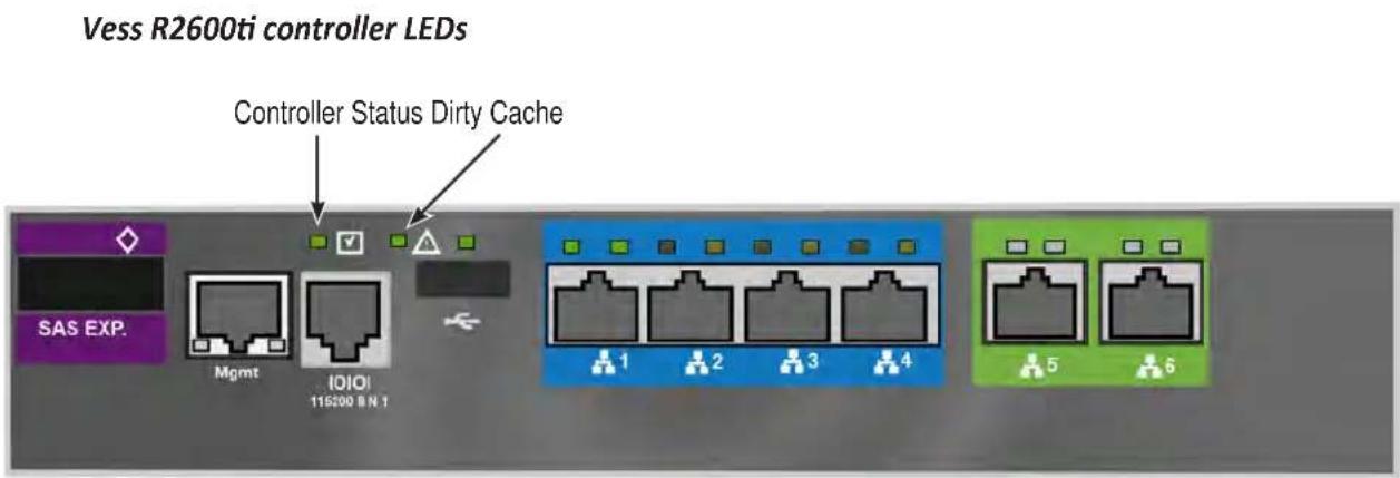


CONTROLLER LED BEHAVIOR
When boot-up is finished and the Vess R2600 subsystem is functioning normally, the Controller status LED displays green continuously; the Management port LEDs display green or flash depending on your network connection; the FC, iSCSI, and SAS Expansion LEDs display green or flash during port activity.
| LED Description | |
| SAS Expansion | Lights green when connected, flashes green when active. |
| Controller Status | This displays the current operational status of the controller. A steady (unblinking) green light indicates the controller is operational. |
| Dirty Cache | Blinks amber if cache is dirty, meaning that the controller memory cache contains data, otherwise this is dark. |
| USB | A steady green light indicates a valid USB connection, this is dark when not connected (no device attached). |
See tables on next page for data port LED behavior.
iSCSI port LED behavior
| 1G iSCSILink/Act and Speed | Two LEDs are located above each port. The left LED lights GREEN when connected, flashes GREEN when there is activity on the port and remains dark no connection has been established. The LED on the right of each port indicates connection speed, GREEN is 100 Mbps, AMBER is 1000 Mbps. |
| 10G iSCSI(Vess R2600ti)Link/Act and Speed | Two LEDs are located above each port. The left LED lights GREEN when connected, flashes GREEN when there is activity on the port and remains dark no connection has been established. The LED on the right of each port indicates connection speed, AMBER is 1000 Mbps, GREEN is 10000 Mbps.Note that the 10G port speed LED indicator is different than the 1G ports, a GREEN speed LED is the fastest speed on the 10G port, in contrast to the 1G iSCSI I/O ports where GREEN is the slowest speed. AMBER indicates 1000 Mbps on both port types. |
Fibre Channel port LED behavior
| LED Description | |||
| FC ports (one LED above each port) | Green Amber | Status | |
| dark dark | Wake-up failure (dead board) | ||
| off on POST failure (dead board) | |||
| off blinking | slowly Wake-up failure monitor | ||
| off blinking | rapidly Failure to POST | ||
| off flashing | POST in progress | ||
| on | off | Failure while functioning | |
| on | on | Failure while functioning | |
| on | 2 rapid blinks | Normal, link up, 2 Gb/s | |
| on | 3 rapid blinks | Normal, link up, 4 Gb/s | |
| on | 4 rapid blinks | Normal, link up, 8 Gb/s | |
| blinking slowly | off | Normal, link down | |
| blinking slowly | blinking slowly | Off offline for download | |
| blinking slowly | blinking rapidly | Restricted offline mode (waiting for restart) | |
| blinking slowly | flashing | Restricted offline mode, test active | |
POWER SUPPLY LEDs
Power Supply, BBU and Cooling Unit LEDs
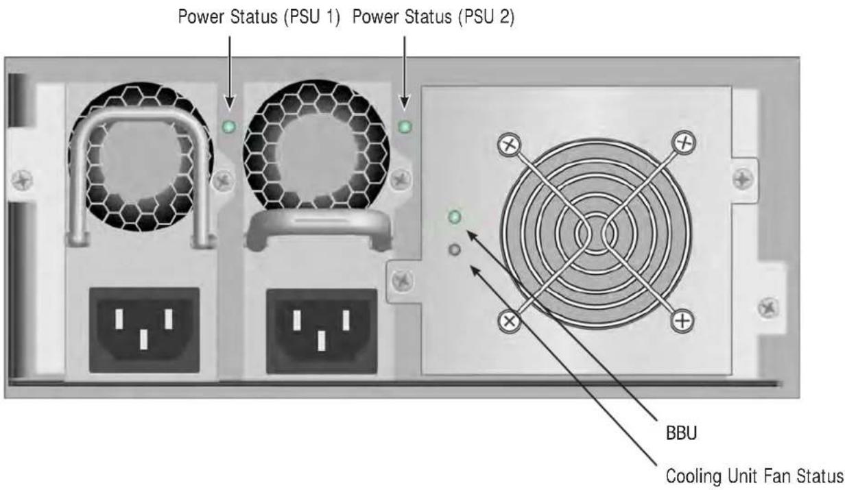
| State | Battery Power Supply Fan | ||
| Dark | No power, Failed or not installed | No power No power | |
| Steady Green | Normal Normal | Normal | |
| Blinking Green | —Locator feature — | ||
| Steady Amber | ——Fan problem | ||
| Flashing Amber | —— | ||
| Steady Red | Failed or battery removed | Failed Failure | |
| Flashing Red | —— |
CHECKING COMPONENT INSTALLATION
To check a component's installation, remove the component, then reinstall the component in its original location. In most cases, this action fixes a bad connection and allows Vess to detect the component. If this action does not correct the problem, replace the unit.
On Vess R2000 systems with dual controllers, when one controller's Status LED is amber and the other controller's Status LED is flashing red, it means that the controller with the flashing red LED has entered maintenance mode. See "RAID Controller Problems" on page 627.
If the Controller Status LED continues to display amber after startup, contact PROMISE Technical Support. See "Contacting Technical Support" on page 666.
The Dirty Cache LED flashes during input/output operation. If the LED shines amber and the power is off, there is unsaved data in the cache. Do NOT power down the Vess while this LED is on.
CLU REPORTS A PROBLEM
The CLU reports information passively, that is you must determine which functions to check based on the sound of the Vess R2600's audible alarm and any amber or red LEDs. See "Vess R2000 is Beeping" on page 604 and "LEDs Display Amber or Red" on page 605 for more information.
Check the event logs first. Then check the reported component.
| Event Severity Levels | |
| Level Description | |
| Fatal | Non-recoverable error or failure has occurred. |
| Critical Action is needed now and the implications of the condition are serious. | |
| Major Action is needed now. | |
| Minor Action is needed but the condition is not a serious at this time. | |
| Warning User can decide whether or not action is required. | |
| Information Information only, no action is required. | |
VIEWING RUNTIME EVENTS
To display Runtime Events:
- From the Main Menu, highlight Event Viewer and press Enter.
The log of Runtime Events appears. Events are added to the top of the list. Each item includes:
- Sequence number – Begins with 0 at system startup.
- Device – Disk Array, Logical Drive, Physical Drive by its ID number.
- Severity – See the Event Severity Level table.
- Timestamp – Date and time the event happened.
-
Description – A description of the event in plain language.
-
Press the up and down arrow keys to scroll through the log.
VIEWING NVRAM EVENTS
This screen displays a list of and information about 63 most important events over multiple subsystem startups.
To display NVRAM events:
- From the Main Menu, highlight Event Viewer and press Enter.
- Highlight NVRAM Events and press Enter.
The log of Runtime Events appears. Events are added to the top of the list. Each item includes:
- Sequence number – Begins with 0 at system startup.
• Device – Disk Array, Logical Drive, Physical Drive by its ID number.
• Severity – See the Table below. -
Timestamp – Date and time the event happened.
• Description – A description of the event in plain language. -
Press the up and down arrow keys to scroll through the log.
CHECKING A REPORTED COMPONENT
In this example, let us check disk array status.
- Open the CLU.
- Highlight Disk Array Management and press Enter.
- Observe the status of your disk arrays.
| DaId | Alias | OpStatus | CfgCapacity | FreeCapacity | MaxContiguousCap |
| 0 | DA0 | OK | 75.44GB | 66.06GB | 66.06GB |
| 1 | DA1 | Degraded | 189.06GB | 179.68GB | 179.68GB |
| 2 | DA2 | OK | 73.57GB | 64.20GB | 64.20GB |
At this point, you can highlight the Degraded array and press Enter to see more information. See below.
Disk Array ID: 1
Physical Capacity: 189.06GB
OperationalStatus : Degraded
MaxContiguousCapacity: 11.18GB
FreeCapacity: 179.68 GB
ConfigurableCapacity: 179.68GB
SupportedRAIDLevels: 0 5 10 1E
Disk Array Alias : DA1
MediaPatrol : Enabled
PDM : Enabled
Transport
Rebuild
Predictive Data Migration
Transition
Dedicated Spare Drives in the Array
Physical Drives in the Array
Logical Drives in the Array
[Locate Disk Array]
Save Settings [CTRL-A]
Restore Settings [CTRL-R]
Return to Previous Menu
From this screen:
• Highlight Physical Drives in the Array and press Enter to identify the failed disk drive
- Highlight Rebuild and press Enter to rebuild the array after you replace the failed disk drive
WEBPAM PROE REPORTS A PROBLEM
WebPAM PROe reports these conditions in the header and all four tabs.
Header
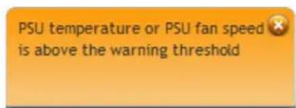
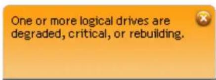
The Header displays popup messages, per your configuration.
Dashboard Tab
System Status
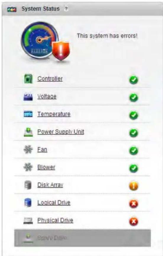
Red X and Yellow! icons identify components that need attention
Event Information
| Index | Device | Event ID | Severity | Time | Description |
| 120 | LD 9 | 0x06001200 | Info | Dec 4, 2013 17:30:41 | Synchronization is stopped internally |
| 119 | LD 9 | 0x04000900 | Major | Dec 4, 2013 17:30:40 | Logical drive has been set to critical |
| 118 | LD 2 | 0x03000900 | Major | Dec 4, 2013 17:30:40 | Logical drive has been placed offline. Possible Data Loss |
| 117 | LD 1 | 0x03000900 | Major | Dec 4, 2013 17:30:40 | Logical drive has been placed offline. Possible Data Loss |
| 116 | LD 9 | 0x03000900 | Major | Dec 4, 2013 17:30:40 | Logical drive has been placed offline. Possible Data Loss |
| 115 | PD 9 | 0x17000D00 | Info | Dec 4, 2013 17:30:40 | A physical disk Page 0 settings has changed |
| 114 | PD 9 | 0x02000D00 | Major | Dec 4, 2013 17:30:40 | Physical Disk is marked as DEAD |
| 113 | LD 9 | 0x02001200 | Info | Dec 4, 2013 17:30:40 | Synchronization is paused |
| 112 | LD 9 | 0x00001200 | Info | Dec 4, 2013 17:30:27 | Synchronization is started |
| 111 | LD 9 | 0x00000900 | Info | Dec 4, 2013 17:30:26 | A new Logical drive has been created |
| Total Count: 121 Page Capacity: 16 Current Page: 1/13 | | | | | | | | | | ||||
Event Severity Levels
| Level | Description |
| Fatal | Non-recoverable error or failure has occurred. |
| Critical Action | is needed now and the implications of the condition are serious. |
| Major Action | is needed now. |
| Minor Action | is needed but the condition is not a serious at this time. |
| Warning User can decide whether or not action is required. | |
| Information Information only, no action is required. | |
DEVICE TAB
Front View, showing the drive carrier icons

Rear View, with Show Internal Components option

Physical Drive View, physical drive shown dead or offline and marked with a red X icon

STORAGE TAB
Disk Arrays
Disk array offline Disk array rebuilding

Logical Drives
Logical drive rebuilding Logical drive offline

ADMINISTRATION TAB
Events icon
| Index | Device | Event ID | Severity | Time | Description |
| 120 | LD 9 | 0x08001200 | Info | Dec 4, 2013 17:30:41 | Synchronization is stopped internally |
| 119 | LD 9 | 0x04000900 | Major | Dec 4, 2013 17:30:40 | Logical drive has been set to critical |
| 118 | LD 2 | 0x03000900 | Major | Dec 4, 2013 17:30:40 | Logical drive has been placed offline. Possible Data Loss |
| 117 | LD 1 | 0x03000900 | Major | Dec 4, 2013 17:30:40 | Logical drive has been placed offline. Possible Data Loss |
| 116 | LD 0 | 0x03000900 | Major | Dec 4, 2013 17:30:40 | Logical drive has been placed offline. Possible Data Loss |
| 115 | PD 9 | 0x17000D00 | Info | Dec 4, 2013 17:30:40 | A physical disk Page 0 settings has changed |
| 114 | PD 9 | 0x02000D00 | Major | Dec 4, 2013 17:30:40 | Physical Disk is marked as DEAD |
| 113 | LD 9 | 0x02001200 | Info | Dec 4, 2013 17:30:40 | Synchronization is paused |
| 112 | LD 9 | 0x00001200 | Info | Dec 4, 2013 17:30:27 | Synchronization is started |
| 111 | LD 9 | 0x00000900 | Info | Dec 4, 2013 17:30:26 | A new Logical drive has been created |
| Total Count: 121 | Page Capacity: 10 | Current Page: 1/13 | |||
Event Severity Levels
| Level | Description |
| Fatal | Non-recoverable error or failure has occurred. |
| Critical Action is needed now and the implications of the condition are serious. | |
| Major Action is needed now. | |
| Minor Action is needed but the condition is not a serious at this time. | |
| Warning User can decide whether or not action is required. | |
| Information Information only, no action is required. | |
Also see these troubleshooting topics:
• "Event Notification Response" on page 644
• "Enclosure Problems" on page 623
USB SUPPORT REPORTS A PROBLEM
This procedure requires a USB flash device:
- Formatted to FAT 32
- At least 50 MB of free space

Caution
Verify that there is no firmware image file on the USB flash device. If a firmware image file is present, the RAID controller might attempt a firmware update.
To collect a service report using the USB Support feature:
- Insert the USB flash device into one of the USB ports on the front left of the Vess R2000.
The controller status LED blinks green in half-second intervals. - Wait until the controller activity LED stops blinking green and displays steady green.
- Remove the USB flash device.
- Insert the USB flash device into a USB port on your PC.
- On the USB flash device, open the OPAX_xxxxxx folder to obtain the re-port and log.
ENCLOSURE PROBLEMS
Enclosure Problems include:
• "Diagnosing an Enclosure Problem" (below)
• "Overheating" on page 625
• "Power Supplies" on page 626
• "Batteries" on page 626
DIAGNOSING AN ENCLOSURE PROBLEM
Check System Status on the Dashboard tab. If a yellow ! or red X appears in the System Status box:
- Click the name link of the component with the red X icon.
The Components List of the Device tab displays.

- Mouse-over Enclosure with the red X icon and click the View button.
The components list expands and shows the power supplies (PSU) and Cooling Units of the Vess R2000 enclosure.

- Click the Back View icon on the Device tab.
- Click the picture of the enclosure.
A popup messages displays the status of each component.
| ID | Status | Location | Operational Status | Healthy Threshold | Current Fan Speed |
| 1 | ✔ | PSU 1 | Functional | >2000 RPM | 10800 RPM |
| 2 | ✔ | PSU 2 | Functional | >2000 RPM | 10800 RPM |
| 3 | ✔ | PSU 3 | Functional | >2000 RPM | 11200 RPM |
| 4 | NA | PSU 4 | Not installed | >2000 RPM | 0 RPM |
| Blowers | |||||
| ID | Status | Location | Operational Status | Healthy Threshold | Current Blower Speed |
| 1 | ✔ | Cooling Unit 1 | Functional | >1400 RPM | 5200 RPM |
| 2 | ✔ | Cooling Unit 1 | Functional | >1400 RPM | 4800 RPM |
| 3 | ✔ | Cooling Unit 2 | Functional | >1400 RPM | 5300 RPM |
| 4 | ✔ | Cooling Unit 2 | Functional | >1400 RPM | 5100 RPM |
When a power supply fan fails, you must replace the power supply. See "Replacing a Power Supply" on page 540.
If the system reports a fan malfunction, contact Technical Support. See "Contacting Technical Support" on page 666 immediately to schedule replacement of the suspect power supply as soon as possible. Running the unit in this condition for more than three weeks may shorten subsystem life and void your warranty.

natural_image
Interior view of an electronic device showing circuit boards, battery cells, and a temperature sensor (no text or symbols visible)OVERHEATING
Overheating is a potentially serious condition because the excessively high temperatures can lead to physical drive failure and controller malfunction.
Overheating usually results from:
- Fan failure
- Inadequate air circulation around the enclosure

Important
In the event of a Cooling Unit failure, DO NOT remove the failed unit until there is a replacement available and on hand. A single functioning Cooling Unit is adequate for cooling the system as long as the failed Cooling Unit remains in place. Removing the failed unit without replacing it will adversely affect airflow within the enclosure resulting in critical overheating and shutdown of the enclosure.
See "Replacing a Power Supply" on page 540.
Inadequate Air Circulation
Air circulation around the Vess R2600 enclosure might be a more complex problem. Use the thermometer icons to help you locate the specific hot spot. Check for these conditions:
• Accumulated dust or objects blocking the fans
- Ambient temperature above 35^ (95°F) where the subsystem is operating
- Failed Cooling Unit
- Less than a minimum of 13 cm (5 inches) space between the back of the enclosure and the wall or other object
To cool down an enclosure:
- Correct any problems identified above.
- Power it down and let it sit for an hour or longer.
If a Cooling Unit must be replaced, do not remove the failed unit until a replacement unit is available. A hole on the back of the enclosure created by a missing Cooling Unit affects air circulation which will cause controller units to overheat and shut down. If a replacement Cooling Unit is not available, leave the failed unit in place until
one is available. See "Replacing a Cooling Unit"
See "Shutting Down the Subsystem" on page 111.
POWER SUPPLIES
Vess R2600 subsystems are equipped with redundant power supplies. The advantage of N+1 power supplies is that should one fail, the other continues to power the subsystem until the faulty one can be replaced. The subsystem is capable of operation on N power supplies.
The power supplies are hot-swappable, meaning you can leave the subsystem running when you replace the bad one. Be careful, however, to remove the faulty power supply and not the good one, or the subsystem comes to an immediate stop and your data is unavailable until the subsystem is powered and booted again.
See "Replacing a Power Supply" on page 540.
POWER FAN FAILURE
In the Vess R2600 subsystems, the power supply fans are used for cooling the power supply. When a power supply fan fails, you must replace the power supply. See "Replacing a Power Supply" on page 540.
BATTERIES
The Cooling Units in the Vess R2600 subsystem use a battery for backup power to protect data in the cache. Should a power failure occur, the battery enables the cache to hold data up to 72 hours. The battery recharges during normal subsystem operation.
In most cases, installing a replacement battery corrects a marginal or failed condition. The battery is located inside the Cooling Unit housing. To replace a battery, first replace the Cooling Unit with the battery that needs to be replaced. See "Replacing a Cache Backup Battery" and "Reconditioning a Battery" on page 121.
RAID CONTROLLER PROBLEMS
RAID controller problems include:
- "Maintenance Mode" (below)
- "Storage Tab" on page 620
- “Taking a RAID Controller out of Maintenance Mode” on page 629
- "Unsaved Data in the Controller Cache" on page 631
Controller problems occur when one of the controllers goes into maintenance mode.
MAINTENANCE MODE
For Vess with two RAID controllers, one of them enters maintenance mode in the event of:
- A difference of some kind between the two controllers (described below)
• An internal controller failure
When a controller enters maintenance mode, it goes offline and it displays N/A (not accessible) under Readiness Status.
You must find and correct the cause of the problem and then take the controller out of maintenance mode (see page 629).
FINDING AND CORRECTING THE CAUSE OF THE PROBLEM
External Checks
Make the following external checks to your Vess subsystem. Be sure that:
- Both RAID controllers are present, fully inserted into their slots, and locked into place.
- The RAID controllers match, meaning both are the same model
- All SAS expansion cables from the RAID controllers to external JBOD units in good condition and are securely connected.

Important
A disconnected SAS expansion cable causes the two RAID controllers to see a different set of configured drives. This condition is the most common cause of a controller entering maintenance mode.
Internal Checks
If all external checks are OK, take the following actions:
- Shut down the Vess.
See "Shutting Down the Subsystem" on page 111. - Remove one of the RAID controllers.
See "Replacing a RAID Controller – Dual Controllers" on page 545. - Restart the Vess.
-
After the Vess is fully booted, view the controller information.
"Viewing Controller Information" on page 113. -
Observe and record the following information about the first controller:
-
SDRAM memory size
- Hardware version
-
Firmware version
-
Shut down the Vess.
- Remove the first controller and install the second controller.
- Repeat steps 3 through 6. Then compare your records.
- Correct any differences between the two controllers. See "Updating Firmware on a RAID Subsystem" on page 118.
TAKING A RAID CONTROLLER OUT OF MAINTENANCE MODE
If you shut down the Vess subsystem in the process of correcting the maintenance mode problem, the affected RAID controller boots into normal mode when the Vess restarts. No further action is required.
If you corrected the problem without shutting down the Vess subsystem, choose one of the following methods to take the controller out of maintenance mode:
- Restart the Vess subsystem. See "Restarting the Subsystem" on page 110.
- Establish a serial connection, then use the CLI (see below) or
- Establish a Telnet connection, then use the CLI (see page 630)
Serial Connection
To clear maintenance mode using a serial connection:
-
Change your terminal emulation program settings to match the following specifications:
-
Bits per second: 115200
- Data bits: 8
- Parity: None
- Stop bits: 1
-
Flow control: none
-
Start your PC's terminal VT100 or ANSI emulation program.
- Press Enter once to launch the CLI.
The login screen appears.
The following steps show the default Administrator user name and pass-word. Use your own user name and password if you have changed these.
- At the Login prompt, type administrator and press Enter.
- At the Password prompt, type password and press Enter.
The CLI screen appears.
The prompt should display MAINTENANCE MODE@cli>.
If the prompt dis-plays your login name, such as administrator@cli>, log into the other controller.
- At the MAINTENANCE MODE@cli> prompt, type maintenance -a exit and press Enter.
The controller reboots. The login screen again appears.
- Close the Serial connection.
Telnet Connection
This procedure requires you to know the IP address of the controller.
To clear maintenance mode using a Telnet connection:
- Go to the command line prompt (Windows) or click the terminal icon (Linux), then run:
telnet 192.168.1.56 2300
The IP address above is only an example. 2300 is the default Telnet port for Vess.
The login screen appears.
The following steps show the default Administrator user name and pass-word. Use your own user name and password if you have changed these.
- At the Login prompt, type administrator and press Enter.
- At the Password prompt, type password and press Enter.
The CLI screen appears.
The prompt should display MAINTENANCE MODE@cli>. If the prompt dis-plays your login name, such as administrator@cli>, log into the other controller.
- At the MAINTENANCE MODE@cli> prompt, type maintenance -a exit and press Enter.
The controller reboots. The Telnet session ends.
UNSAVED DATA IN THE CONTROLLER CACHE
The dirty cache LED (marked with the icon) informs you that there is data in the cache that has not been saved to non-volatile memory. Such data is sometimes called "dirty," not to suggest it is corrupted in some way but because it has not been saved to a physical drive.
Dirty Cache LED


Caution
If there is unsaved data in the controller's cache, the dirty cache LED shines amber. During this time, do NOT power down the Vess. Wait until the LED goes dark.
PHYSICAL DRIVE PROBLEMS
Physical drives are the foundation of data storage. A physical drive problem can affect your entire RAID system.
When a yellow ! icon or a red X icon appears beside a physical drive, check the drive's operational status:
- Click the Device tab.
- Click the Physical Drive icon.
- Click the physical drive you want, then click the View button.
Look under Operational Status for the condition of the physical drive.
- Offline – Check the drive for:
- PFA Condition – Caused by a bad block or sector. See Note 1 below.
- Stale Condition – Caused by obsolete array information on the physical drive. See Note 2 below.
- Not Usable – This condition occurs when you have:
- Two controllers in your RAID subsystem and a SATA drive without a SAS-to-SATA adapter. See Note 3 below.
- A missing or defective SAS cable between the RAID subsystem and a JBOD expansion unit.
- Drive Failed or Dead – The physical drive cannot be repaired. You must replace the failed drive. See Note 4 below.
Note 1: Clear the error condition. Then the physical drive is available. See "Clearing a Stale or a PFA Condition" on page 187.
Note 2: Identify the disk array to which the physical drive belongs. Then delete the disk array. If the error condition remains on the physical drive, clear the error condition.
Note 3: Obtain SAS-to-SATA adapters though PROMISE Technology, at
http://www.promise.com. See "Installing Physical Drives" on page 35 for installation instructions.
Note 4: You can set the number of bad blocks tolerated before the controller marks a physical drive as Dead. See "Managing Background Activities" on page 144, "Making PDM Settings" on page 155. See also "Running Media Patrol on a Disk Array" on page 194 and "Disk Array Degraded / Logical Drive Critical" on page 633.
DISK ARRAY AND LOGICAL DRIVE PROBLEMS
Disk array and logical drive problems include:
- "Disk Array Degraded / Logical Drive Critical" (below)
- "Disk Array Offline / Logical Drive Offline" on page 634
- "Repairing an Offline Disk Array or Logical Drive" on page 635
- "Rebuilding a Disk Array" on page 636
- "Incomplete Array" on page 636
Disk array problems typically result from a physical drive failure. The most common problem is a degraded disk array. The RAID controller can rebuild a degraded disk array. See "Rebuilding a Disk Array" on page 636.
DISK ARRAY DEGRADED / LOGICAL DRIVE CRITICAL
Disk arrays are made up of physical drives. Logical drives are created on the disk array.
When one of the physical drives in a disk array fails:
• The operational status of the disk array becomes Critical.
- The operational status of the logical drives becomes Critical or Degraded.
- The operational status of the physical drive becomes Dead or Offline.
WebPAM PROe reports these conditions in the following places:
- Dashboard tab
A yellow ! icon beside the disk arrays, logical drives, and physical drives under System Status.
Major event for the logical drive under Event Information.
Warning event for the physical drive under Event Information.
- Device tab
Front View – Physical drives are shown Dead or Offline and marked with a red X icon, or Missing.
Physical Drive View – Physical drives are shown Dead or Offline and marked with a red X icon, or Missing.
- Storage tab
Disk Array and Logical Drive are marked Critical with a yellow ! icon.
RAID 6 and 60 logical drives are marked:
- Degraded with a yellow ! icon when ONE physical drive is offline.
• Critical with a yellow ! icon when TWO physical drives are offline.
RAID 0 logical drives show Offline status and a red X icon.
If there is no spare drive or unconfigured drive in the RAID system, you must provide the replacement drive. See "Installing Physical Drives" on page 35.
- Administration tab
Depending on your settings and availability of a replacement drive, your system automatically rebuilds the degraded disk array. See "Rebuilding a Disk Array" on page 636.
The system sends an Email message about the incident to subscribing users, depending on user settings. See "Setting User Event Subscriptions" on page 141.
Disk arrays are made up of physical drives. Logical drives are created on the disk array. When a disk array and its logical drives go Offline, the data stored in the logical drives is no longer accessible.
RAID 0 logical drives go Offline when ONE physical drive is removed or fails.
RAID 1, 1E, 5, 10, and 50 logical drives go Offline when TWO physical drives are removed or fail.
RAID 6 and 60 logical drives go Offline when THREE physical drives are re-moved or fail.
WebPAM PROe reports these conditions in the following places:
- Dashboard tab
A red X icon appears beside the disk arrays, logical drives, and physical drives under System Status.
Major event for the logical drive under Event Information
Warning event for the physical drive under Event Information.
- Device tab
On Front View and Physical Drive View, physical drives are shown Dead, Offline, or Missing.
- Storage tab
Disk array and logical drives are marked with a red X icon.
- Administration tab
Under Background Activities, no Rebuild takes place. See "Repairing an Offline Disk Array or Logical Drive",
below.
The system sends an Email message about the incident to subscribing users, depending on user settings. See "Setting User Event Subscriptions" on page 141.
REPAIRING AN OFFLINE DISK ARRAY OR LOGICAL DRIVE
RAID 1, 1E, 5, 6, 10, 50, and 60 Logical Drives
If a fault-tolerant logical drive, RAID 1, 1E, 5, 6, 10, 50, and 60, goes Offline, it may be possible to recover your data.

Warning
Take no further corrective action until you have consulted with Technical Support!
RAID 0 Logical Drives
If a logical drive based on a non-fault-tolerant disk array, RAID 0, goes offline, all of the data on the logical drive is lost.
To recreate your logical drive:
- Identify the failed physical drive. See "Locating a Physical Drive" on page 185.
- Replace the failed drive. See "Installing Physical Drives" on page 35.
- If the disk array had more than one physical drive, delete the disk array and re-create it.
See "Deleting a Disk Array" on page 192 and "Creating a Disk Array Manually" on page 190. - Restore the data from your backup source.
REBUILDING A DISK ARRAY
When you rebuild a disk array, you are actually rebuilding the data on one physical drive.
- When a physical drive in a disk array fails and a spare drive of adequate capacity is available, the disk array begins to rebuild automatically using the spare drive.
- If there is no spare drive of adequate capacity, but the Auto Rebuild function is ENABLED, the disk array begins to rebuild automatically as soon as you remove the failed physical drive and install an unconfigured physical drive in the same slot. See “Making Rebuild Settings” on page 153.
- If there is no spare drive of adequate capacity and the Auto Rebuild function is DISABLED, you must replace the failed drive with an unconfigured physical drive, then perform a Manual Rebuild. See "Rebuilding a Disk Array" on page 196.

Important
If your replacement disk drive was formerly part of a different disk array or logical drive, you must clear the configuration data on the replacement drive before you use it. See "Clearing a Stale or a PFA Condition" on page 187.
INCOMPLETE ARRAY
A more serious, but far less common problem is an Incomplete Array. An in-complete array results from a physical drive that fails or becomes missing during:
• RAID level migration
- Disk array transport
Migration
Normally, if a physical drive or the controller fails during migration, the disk array goes critical, and you can rebuild it.
Transport
Transport is the action of moving the physical drives of a disk array:
• To different slots in the same enclosure
• From one enclosure to another
If a physical drive fails during a transport, or you do not move all of the physical drives to their new locations, WebPAM PROe displays an incomplete array. When WebPAM PROe discovers an incomplete array, it displays a dialog box asking you to:
- Click the OK button to accept the incomplete array.
- Click the Cancel button to reject the incomplete array.
Accepting an Incomplete Array
Before you accept the incomplete array, be sure all of the physical drives are present and that their drive carriers are properly installed into the enclosure. See "Installing Physical Drives" on page 35.
If you choose to accept the incomplete array:
- Click OK in the incomplete array dialog box.
- Check the operational status of the logical drives in the array.
• If the logical drives are Critical, proceed with a rebuild.
- If the logical drives are Offline, contact Technical Support. See "Contacting Technical Support" on page 666.
- Restore your data from a backup source.
If you choose NOT to accept the incomplete array:
- Click Cancel in the incomplete array dialog box.
-
Do one of the following:
-
Delete the array. This action deletes all logical drives on the array.
- Replace the missing physical drive.
CONNECTION PROBLEMS
Connection problems include:
- "Serial Connections" (below)
• "Network Connections" on page 639
• "Fibre Channel Connections" on page 640
• "SAS Connections" on page 640
- "Browser Does Not Connect to WebPAM PROe" on page 642
Connection problems cause a majority of failures in almost any electrical system. While the installation of the cables and components was correct, they don't function properly, or at all, because:
• A connector is dirty or corroded
• A connector is loose or damaged
• A cable looks OK outside but has an open circuit inside
• The wrong cable was used
The Vess R2000 ships with a full set of new cables, as required for each specific model. Be sure to use these components because: 1.) They are the proper ones for your RAID subsystem, 2.) They are in brand-new condition, and 3.) You paid for them with the purchase of your subsystem.
SERIAL CONNECTIONS
Vess uses a serial connection for the command line interface (CLI). After you set the IP address, you can access the CLI through a network connection, also. Normally, users prefer WebPAM PROe because of its graphic user interface. But the CLI can do the same jobs. And it works when your network connection is down.
For Vess, you must use the CLI to set the Management Port IP address in order for WebPAM PROe to connect with it. See "Making a Serial Connection" on page 299 and "Setting-up the Serial Connection" on page 67 for more information on making the connection. This issue is discussed further under Network Connections, below.
The CLI controls and manages but does not move data. The CLI communicates through a RJ11-to-DB9 serial data cable, supplied with the Vess. You may choose not use the CLI often and want to disconnect and store the cable. Consider leaving it connected, so you know where it is the next time you need it.
NETWORK CONNECTIONS
Each RAID controller has an Ethernet (RJ45) management port connector on the back of the enclosure. This is a 100 Mbps Ethernet connector designed to connect to your network. The Vess becomes a node on your network like any other PC, server or other component with an IP address.
Vess ships from the factory IP addresses of 10.0.0.1, 10.0.0.2, and 10.0.0.3. You must change these addresses to ones that work on your network. You make the initial IP address setting using the CLI. See "Making a Serial Connection" on page 299 and "Setting-up the Serial Connection" on page 67.
Management port connection on the RAID controller
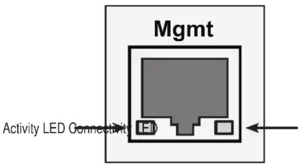
Management Port LEDs
| State Activity | Connectivity | |
| Dark No activity | 10BaseT | |
| Steady green — 100BaseT | ||
| Flashing green Activity — | ||
Note that the virtual and maintenance ports can accept IP address assignments from a DHCP server.
If you manually assigned an IP address to the Vess R2000 but there is a DHCP server on your network, there is a chance that the server might assign the IP address to another node. You might see a warning to this effect on your PC's monitor. If this happens, WebPAM PROe may not be able to connect. See your network administrator to work out a suitable arrangement.
FIBRE CHANNEL CONNECTIONS
When there is a connection failure, use WebPAM PROe to verify that Vess sees the initiators. See “Viewing a List of FC Initiators on the Fabric” on page 230.
If Vess sees some initiators but not the one you want, the problem is most likely elsewhere in the loop or fabric. If Vess does not see any initiators:
- Check all of the Fibre Channel connections
- Verify that all nodes are properly connected and powered
- Verify that the fabric router or switch is properly connected powered
For more information, see "Managing Fibre Channel Connections" on page 227.
SAS CONNECTIONS
Faulty SAS expansion connections are suspected when the link port counter reports a large number of bad link errors.
Link errors can be caused by:
- Debris blocking the SAS cable connector
• A faulty SAS cable
• A faulty controller or I/O module SAS connector
Blocked Cable Connectors
To check for debris blocking the SAS cable connector:
- Power down the RAID subsystem and JBOD units.
- Remove the SAS cable and check all SAS connectors for debris.
- Clean the connectors as required and reconnect the SAS cable.
- Power up the subsystems and monitor the link port counter for changes in the rate of link error accumulation.
Faulty Cable
To check for a faulty SAS cable:
- Power down the RAID subsystem and JBOD units.
- Replace the SAS cable with a new one.
- Power up the subsystems and monitor the link port counter for changes in the rate of link error accumulation.
Faulty Controller or I/O Module Connector
To check for a bad controller or I/O module SAS connector:
- With the subsystems online and I/Os running, access the CLI via serial or Telnet.
See "Initial Connection" on page 206. - At the command prompt, type the following command and press Enter.
administrator@cli> sasdiag -a errorlog -l expander -e 1 -i 1 - At the command prompt, type the following command and press Enter.
administrator@cli> sasdiag -a errorlog -l c2cport
By interpreting the two error logs, you can verify which controller or I/O module SAS port is accumulating link errors.
BROWSER DOES NOT CONNECT TO WEBPAM PROE
If you successfully setup and connected to WebPAM PROe, then suddenly you can no longer connect, it might be the result of the following three conditions:
- DHCP is enabled on your Vess's virtual management port
- The DHCP server does not have a dedicated IP address for the Vess
- The Vess restarted and your DHCP server assigned a new IP address
You must obtain the new IP Address for the virtual management port in order to direct your browser to the Vess and start WebPAM PROe.
To access the new IP address:
- Start your PC's terminal VT100 or ANSI emulation program.
- Press Enter once to launch the CLI.
- At the Login prompt, type administrator and press Enter.
- At the Password prompt, type password and press Enter.
- Type net and press Enter.
administrator@cli> net
| CId | Port Type | IP | Mask | Gateway | Link | |
| Virtual | Mgmt | 192.168.10.85 | 255.255.255.0 | 192.168.10.1 | Up | |
The new virtual management port IP address and other network settings display.
- Enter the new IP address into your browser to log into WebPAM PROe.
For more information, see "Making a Serial Connection" on page 299, also "Setting-up the Serial Connection" on page 67, "About IP Addresses" on page 68, and "Logging into WebPAM PROe" on page 82.
POWER CYCLING THE SUBSYSTEM
To power cycle a RAID subsystem means to:
- Shut down
- Turn off the power
- Turn on the power
- Restart
Power cycling is sometimes required as a remedial action but only when prompted by a message from software or when directed by Technical Support.
To power cycle the RAID subsystem:
- Shut down the subsystem.
When the controllers shut down, your network connection is lost. - Manually turn off the system power by pressing the power button of the RAID unit for over five seconds.
- Wait at least 10 seconds.
- Manually press the power button of the JBOD units.
- Manually press the power button of the RAID subsystem.
- Wait no less than two minutes.
-
Do one of the following actions:
-
Open your browser and log into WebPAM PROe.
- Re-establish your Telnet or SSH connection to the subsystem and open the CLU.
If you cannot log in immediately, wait 30 seconds and try again.

Important
If your RAID subsystem manages JBOD expansion units, always power on the JBOD expansion units first. Then power on the RAID subsystem.
EVENT NOTIFICATION RESPONSE
When you choose Event Notification, WebPAM PROe sends popup and/or email messages regarding its status.
The messages you see depend on your notification selection and what is currently happening in the Vess. See
"Setting User Event Subscriptions" on page 141.
The table below cites:
• Reported Events – Events that require you to take action
- Corrective Actions – The action you should take in response to the event
A list of event categories is shown below.
- "Battery" on page 645
- "BBU" on page 645
- "Blade Server" on page 646
- "Cache" on page 646
- "Controller" on page 647
- "CRC" on page 649
- "Disk Array" on page 649
- "Drive Interface" on page 650
- "Enclosure" on page 650
• "Event Log" on page 650
• "Fibre Channel" on page 651 - "Firmware Update" on page 651
- "Host Interface" on page 652
- "Initiator" on page 654
- "JBOD" on page 654
• "Logical Drive" on page 654
• "Media Patrol" on page 656 - "Online Capacity Expansion" on page 656
-
"Parity" on page 656
-
"PDM" on page 657
• "Physical Disk" on page 658 - "PSU (Power Supply Units)" on page 660
- "PSU Fans" on page 660
• "RAID Level Migration" on page 661 - "Rebuild" on page 662
• "Redundancy Check" on page 662
• "Resource" on page 663 - "SCSI" on page 663
- "SEP" on page 663
- "Spare Check" on page 663
- "Spare Drives" on page 663
- "SMART" on page 664
- "Stripe Level Migration" on page 664
• "Synchronization" on page 665 - "Subsystem (Vess)" on page 665
- "Transition" on page 665
- "Unknown" on page 665
- "Zoning" on page 665
| Reported Event Corrective Action | |
| Battery | |
| Battery is inserted | No action is required. |
| Battery charging has failed | Replace the battery. |
| Battery reconditioning has started | No action is required. |
| Battery reconditioning has been terminated | Replace the battery. |
| The write policy of writeback logical drive switched from writeback to writethru | Check the event log to see whether battery is re-conditioning. |
| The write policy of writeback logical drive switched from writethru to writeback | No action is required. |
| Battery is charging in high temperature | Monitor the condition. Contact Tech Support if the problem persists. |
| Battery cannot function with the enclosure or with the attached battery board | Wrong battery installed. Contact Tech Support for assistance. |
| Logical drive writeback cache maybe enabled without battery support | No action required. |
| Battery is fully charged | |
| Battery is not present | Install a battery or verify that the battery is properly connected. |
| Battery is not accessible | Connect the battery properly or replace the battery. |
| BBU | |
| BBU flushing has started | No action is required. |
| BBU flushing has ended | |
| BBU flushing has failed | Contact Tech Support if the condition persists. |
| Blade Server | |
| Blade Server Inserted | No action is required. |
| Blade Server Removed | |
| Cache | |
| Not available | Contact Tech Support. |
| Controller | |
| The controller parameter(s) are changed by user | No action is required. |
| The controller is reset by Watch Dog timer | Result of a firmware update. If the condition persists, replace the controller. |
| The controller has new crash information | Contact Tech Support. |
| The controller's heart beat has started | No action is required. |
| The controller's heart beat has stopped | |
| The partner controller's heart beat has started | |
| The partner controller's heart beat has stopped | |
| The partner controller's heart beat has skipped | |
| The controller's main scheduler has frozen | Contact Tech Support if the condition persists. |
| Controller has entered maintenance mode since configured physical disk seen by partner controller is not seen here | Verify that all SATA drives have an SAS-to-SATA adapter installed. |
| Controller has entered maintenance mode due to mismatch of physical disks types | Check and correct SAS cabling and connections as needed. |
| Controller has entered maintenance mode due to mismatch of physical disk WWN | Update to the latest firmware. If the condition persists, replace the controller. |
| Controller has entered maintenance mode due to mismatch of SATA Disks | Check and correct data cabling and connections as needed. |
| Controller has entered maintenance mode due to mismatch of Disk IDs | |
| Controller has entered maintenance mode since no physical disks are seen as seen by Partner controller | |
| Controller | |
| Controller is started | No action is required. |
| Controller is set to Active Mode | |
| Controller is set to Standby Mode | |
| Controller Failed Over as partner is removed | Verify that the partner controller is properly installed and all cables are connected. |
| Controller Failed Over as heart beat stopped | |
| Controller Firmware mismatch with that of the partner controller | Auto Firmware synchronization upgrades or downgrades the firmware. |
| Controller set to Maintenance Mode because of hardware mismatch with partner (controller) | Compare controller types and amount of memory installed. Correct or update as needed. |
| Controller set to Maintenance Mode because of firmware mismatch with partner controller | Update this controller to the same firmware version as the partner controller. |
| Controller set to Maintenance Mode because Firmware is flashing in the partner controller | Exit out of Maintenance mode after firmware flashing is complete. |
| Controller set to Maintenance Mode because of flash image version mismatch with partner (controller) | Update this controller to the same flash image version as the partner controller. |
| Controller has been set to Maintenance mode because there is a mismatch in the Controller Model or Hardware version with that of the partner controller | Replace this controller with the same Model and Hardware version as the partner controller. |
| Controller has been set to Maintenance mode because there is a mismatch in the memory size with that of the partner controller | Replace this controller's memory with the same memory size as the partner controller |
| Partner Controller has entered maintenance mode to protect user data since one of the configured physical drives was disconnected in the partner controller | Check and correct cable connections to external JBOD enclosures. Rebuild any critical logical drives. Back up array data. Replace the physical drive. Bring controller out of maintenance mode. |
| Controller was placed on reset during Fail Over processing | No action is required. |
| Partner Controller was placed on reset during Fail Over processing | |
| Controller was reset as it was not able to join the running partner controller | Verify that the controller is running. If the condition persists, replace the controller. |
| The controller has reset because it encountered a firmware problem | If resets happen frequently, update to new firmware or replace the controller. |
| Controller temperature is above the warning threshold | Check airflow around the Vess. Check blowers and fans. |
| The controller temperature is above controller critical threshold | No action is required. |
| Controller temperature is within the normal range | |
| CRC | |
| CRC error is detected while receiving CMD information unit | If this message appears repeatedly, contact Tech Support. |
| CRC error is detected during Data Out phase | |
| Disk Array | |
| New disk array has been created | No action is required. |
| Disk array has been deleted | |
| Disk array has been added | |
| Disk array has been removed | |
| Disk array settings have been changed | |
| Disk array is transport ready | Remove physical drives in disk array and insert them into a different subsystem. To cancel Transport Ready Status, remove and reinsert the drives in their original slots. |
| Drive Interface | |
| Drive-interface controller is found | No action is required. |
| Drive-interface controller is NOT found | Restart the Vess. If this message appears repeatedly, contact Tech Support. |
| Drive-interface diagnostics has passed | No action is required. |
| Drive-interface diagnostics has failed | Restart the Vess. If this message appears repeatedly, contact Tech Support. |
| Drive-interface controller has generated a general parity error | If this message appears repeatedly, contact Tech Support. |
| Drive-interface controller has generated a data parity error | |
| Enclosure | |
| Enclosure temperature is above the threshold | Check blowers and fans. |
| Enclosure temperature is above the warning threshold | Check airflow around the Vess. Check blowers and fans. |
| Enclosure temperature is above the critical threshold | |
| Enclosure temperature is within the normal range | No action is required. |
| Shut down PSUs due to enclosure or controller temperature over threshold | Shut down the Vess |
| Event Log | |
| Event logging is enabled | No action is required. |
| Event logging is disabled | |
| Event log buffer is cleared in RAM | |
| Event log buffer is cleared in NVRAM | |
| Event log buffer is cleared in MDD | |
| Fibre Channel | |
| Fibre Channel controller has detected bus reset | If this message appears repeatedly, contact Tech Support. |
| Fibre Channel controller has received a “LUN reset” command. | No action is required. |
| Fibre Channel controller has encountered a fatal error | Restart the Vess. If this message appears repeatedly, contact Tech Support. |
| Fibre Channel link is up | No action is required. |
| Fibre Channel link is down | |
| Fibre Channel controller settings have changed | |
| Firmware Update | |
| Firmware update is started | No action is required. |
| Firmware update is complete | |
| Firmware update is fail | Try the update again. If this message repeats, contact Tech Support. |
| Back-end expander firmware upgrade is started | No action is required. |
| Back-end expander firmware upgrade is completed | |
| Back-end expander firmware upgrade failed | Try the update again. If this message repeats, contact Tech Support. |
| Front-end expander firmware upgrade is started | No action is required. |
| Front-end expander firmware upgrade is completed | |
| Front-end expander firmware upgrade failed | Try the update again. If this message repeats, contact Tech Support. |
| Host Interface | |
| Host interface controller has detected bus reset | If this message appears repeatedly, contact Tech Support. |
| Host interface controller has encountered an unrecoverable error | Restart the Vess. If this message appears repeatedly, contact Tech Support. |
| Host interface controller has received an “abort task” command. | No action is required. |
| Host interface controller has received an “abort task set” command. | |
| Host interface controller has received a “clear ACA” command. | If this message appears repeatedly, contact Tech Support. |
| Host interface controller has received a “clear task set” command. | No action is required. |
| Host interface controller has received a “LUN reset” command. | |
| Reported Event Corrective Action | |
| Host Interface | |
| Host interface controller is informed that the initiator has detected an error | If this message appears repeatedly, contact Tech Support. |
| Host interface controller has received illegal secondary identification | |
| Host interface controller has received a message parity error | |
| Host interface controller has received a bus reboot | |
| Host interface link is up | No action is required. |
| Host interface link is down | Check connections. |
| Host interface controller has encountered an unknown error | If this message appears repeatedly, contact Tech Support. |
| Host interface controller has encountered a system error | |
| Host interface controller has encountered a fatal error | Restart the Vess. If this message appears repeatedly, contact Tech Support. |
| Host interface controller settings have changed | No action is required. |
| Host interface controller has received a ‘WARM reset’ command | If this message appears repeatedly, contact Tech Support. |
| Host interface controller has received a “COLD reset” command | |
| Host Interface controller, MU handshake failed | |
| Host Interface controller, HMU has stopped | |
| Host Interface controller, FMU has unloaded | |
| Reported Event Corrective Action | |
| Initiator | |
| Initiator sent message for detecting an error | If this message appears repeatedly, contact Tech Support. |
| JBOD | |
| JBOD system connected | No action is required. |
| JBOD system either is removed or malfunctioned | Check Expander firmware and SAS connections. |
| Logical Drive | |
| Logical drive initialization has started | No action is required. |
| Logical drive Initialization is in progress | |
| Logical drive initialization has completed | |
| Logical drive initialization has paused | Resume the initialization when ready. |
| Logical drive initialization has resumed | No action is required. |
| Logical drive initialization has stopped | If this action was not intentional, check the logical drive's status. |
| Logical drive initialization marks the logical drive offline | Replace the failed physical drive. Delete and recreate the logical drive. |
| Logical drive initialization is aborted due to an internal error. | Reduce system load on the Vess. |
| Logical drive initialization is queued | No action is required. |
| Quick logical drive initialization has started | |
| Quick logical drive initialization has completed | |
| Quick logical drive initialization has paused | Resume the initialization when ready. |
| Quick logical drive initialization has resumed | No action is required. |
| Quick logical drive initialization has stopped | If this action was not intentional, check the logical drive's status. |
| Quick logical drive initialization marks the logical drive offline | Replace the failed physical drive. Delete and recreate the logical drive. |
| Quick logical drive Initialization is aborted due to an internal error | Reduce system load on the Vess. |
| Logical Drive | |
| Quick logical drive initialization is queued | No action is required. |
| A new logical drive has been created | |
| Logical drive has been deleted | |
| Logical drive has been placed online | |
| Logical drive has been placed online. Possible data loss | Check the state of the physical drives, replace any bad drives. Rebuild logical drive. |
| Logical drive has been set to critical. | |
| Logical drive has been set to degrade | |
| Rebuild marks the logical drive synchronized upon rebuild completion | No action is required. |
| Logical drive settings has been changed through a user command | |
| One of the error tables of a logical drive has been cleared by the user | |
| Logical drive axle has been placed online | |
| Media Patrol | |
| Media patrol is started | No action is required. |
| Media patrol is in progress | |
| Media patrol is completed | |
| Media patrol is paused | Resume Media Patrol when ready. |
| Media patrol is resumed | No action is required. |
| Media patrol is stopped | If this action was not intentional, check the logical drive's status. |
| Media patrol is aborted due to an internal error. | Reduce system load on the Vess. |
| Media patrol is queued | No action is required. |
| Media patrol is stopped internally | |
| Online Capacity Expansion | |
| Online capacity expansion has started | No action is required. |
| Online capacity expansion has completed | |
| Online capacity expansion has paused | Resume OCE when ready. |
| Online capacity expansion has resumed | No action is required. |
| Online capacity expansion has stopped | If this action was not intentional, check the logical drive's status. |
| Online capacity expansion has encountered a physical disk error | Check the physical drive check table after OCE is finished. |
| Online capacity expansion is aborted due to an internal error. | Reduce system load on the Vess. |
| Online capacity expansion is queued | No action is required. |
| Parity | |
| Parity error is detected during Data Out phase | If this message appears repeatedly, contact Tech Support. |
| Reported Event Corrective Action | |
| PDM | |
| PDM is started | No action is required. |
| PDM is in progress | |
| PDM is completed | |
| PDM is paused | Resume PDM when ready. |
| PDM is resumed | No action is required. |
| PDM is stopped | If this action was not intentional, check the disk array's status. |
| PDM is switched to rebuild. | Replace the dead physical drive or reinstall the missing drive. |
| PDM is stopped internally | The destination drive was removed or used for a rebuild. |
| Reported Event Corrective Action | |
| Physical Disk | |
| Physical disk is marked online | No action is required. |
| Physical disk is marked offline | Replace the physical drive.Physical disk is marked as DE |
| Physical disk has been reset | |
| Physical disk assigned as global spare | No action is required. |
| Global Spare has been deleted | |
| Physical Disk is no longer assigned as a global spare | |
| Physical disk assigned as dedicated spare | |
| Dedicated Spare has been deleted | |
| Physical Disk is no longer assigned as a dedicated spare | |
| Physical disk has been inserted | |
| Physical disk has been removed | Insert the physical drive back into the system. |
| Command on physical disk has been re-tried | If this message appears repeatedly, replace the physical drive |
| Physical disk ECC error is detected | Replace the physical drive. |
| Physical disk CRC error is detected | |
| Bad sector is found on physical disk | If this message appears repeatedly, replace the physical drive. |
| Error is detected in remap sectors | |
| Command times out on physical drive | |
| Physical disk negotiation speed is decreased. | |
| Previously configured disk is no longer found | Insert the physical drive back into the system. |
| A physical disk has encountered an unknown (non-ECC) media error. | If this message appears repeatedly, replace the physical drive. |
| A physical disk has encountered PFA condition | Clear the PFA condition. If this message appears repeatedly, replace the physical drive. |
| A configured dead physical drive has been inserted | Replace the physical drive. |
| A physical drive page 0 settings have been changed | No action is required. |
| A physical drive page 1 settings have been changed (SATA drives) | |
| A physical drive page 3 settings have been changed (SAS drives) | |
| Reported Event Corrective Action | |
| Physical Disk | |
| Physical disk is marked as DEAD due to removal | Replace the physical drive. |
| Physical disk is marked as DEAD due to failure of reassign sectors command | |
| Physical disk is marked as DEAD due to PFA condition | |
| Physical disk is marked as DEAD due to forced offline state | |
| Physical disk seen by partner controller not seen here | Check and correct SAS connections. Verify that SAS-to-SATA adapters are installed on all SATA drives. |
| Single ported physical disk seen by Partner controller not seen here | Install an SAS-to-SATA adapter on the SATA drive. |
| Physical disk reported not ready | Replace the physical drive. |
| Reported Event Corrective Action | |
| PSU (Power Supply Units) | |
| PSU is not inserted | Reinstall the power supply unit. |
| PSU is off | Turn on the power supply or plug in the power cable. |
| PSU is on | No action is required. |
| PSU is installed and turned on | |
| PSU is functional and turned on | |
| PSU is installed and turned off | Turn on the power supply or plug in the power cable. |
| PSU is functional and turned off | |
| PSU is malfunctioning and turned on | Replace the power supply unit. |
| PSU is malfunctioning and turned off | |
| PSU has been removed | |
| PSU 12V/5V/3.3V power is out of the threshold range | |
| PSU 12V/5V/3.3V power is within the normal range | No action is required. |
| PSU is critical. This may cause instability of the system | Check the power to the PSU. Verify that the correct PSU is installed. |
| PSU Fans | |
| PSU fan or blower has turned on | No action is required. |
| PSU fan or blower has turned off | |
| PSU fan or blower speed is increased | |
| PSU fan or blower speed is decreased | |
| PSU fan or blower is malfunctioning | Replace the power supply. |
| PSU fan or blower is inserted | No action is required. |
| PSU fan or blower is functioning normally | |
| PSU fan or blower is NOT installed | Check fans or blowers. |
| PSU fan status is unknown. | Check for proper installation and turn on the power supply. If the condition persists, replace the power supply. |
| Reported Event Corrective Action | |
| RAID Level Migration | |
| RAID level migration is started | No action is required. |
| RAID migration is in progress | |
| RAID level migration is completed | |
| RAID level migration is paused | Resume migration when ready. |
| RAID level migration is resumed | No action is required. |
| RAID level migration is stopped | If this action was not intentional, check the logical drive's status. |
| RAID level migration has encountered a physical disk error | Check the disk drive check table after migration and replace disk drive as needed. |
| RAID level migration is aborted due to an internal error. | Reduce system load on the Vess. |
| RAID level migration is queued | No action is required. |
| Migration has detected stale NV Watermark | Wait to see if the watermark clears. |
| Migration has cleared stale NV Watermark | No action is required. |
| Array was made incomplete due to missing NV Watermark | If the array is online, try migration again. If the array is offline, delete and recreate the array. |
| User has accepted Incomplete Array. (Caused by a missing NV Watermark) | Rebuild the disk array. |
| Rebuild | |
| Rebuild is started | No action is required. |
| Rebuild is in progress | |
| Rebuild is completed | |
| Rebuild is paused | Resume rebuild when ready. |
| Rebuild is resumed | No action is required. |
| Rebuild is stopped | If this action was not intentional, check the logical drive's status. |
| Rebuild stopped internally | Contact Tech Support. |
| Rebuild is aborted | Reduce system load on the Vess. |
| Rebuild is queued | No action is required. |
| Auto rebuild cannot start | Install a target physical drive of adequate capacity. |
| Redundancy Check | |
| Redundancy Check is started | No action is required. |
| Redundancy Check is completed | |
| Redundancy Check is paused | Resume Redundancy Check when ready. |
| Redundancy Check is resumed | No action is required. |
| Redundancy Check is stopped | |
| Redundancy Check is aborted due to internal error | Reduce system load on the Vess. |
| Redundancy Check encountered inconsistent block(s) | Check the disk drive check table after RC and replace disk drive as needed. |
| Redundancy Check task is queued | No action is required. |
| Redundancy check is in progress | |
| Redundancy Check task is stopped internally | Restore the disk array to functional status. |
| Redundancy check is started on unsynchronized logical drive | No action is required. |
| Resource | |
| Resource is NOT available | Reduce system load on the Vess. |
| SCSI | |
| SCSI host interface controller settings have changed | No action is required. |
| SEP | |
| SEP is found No action is required. | |
| SEP is NOT found Insert or replace SEP hardware. | |
| SEP I2C device access failure | f this message appears repeatedly, contact Tech Support. |
| SEP I2C device access recovered from failure | |
| Spare Check | |
| Spare check started on the given spare drive | No action is required. |
| Spare check completed successfully on the given spare drive | |
| Spare Drives | |
| Physical disk assigned as global spare | No action is required. |
| Physical disk is no longer assigned as global spare | |
| Global Spare has been deleted | |
| Physical disk assigned as dedicated spare | |
| Physical disk is no longer assigned as dedicated spare | |
| Dedicated Spare has been deleted | |
| SMART | |
| SMART error is received | If this message appears repeatedly, replace the physical drive. |
| Stripe Level Migration | |
| Stripe Level migration is started | No action is required. |
| Stripe Level migration is completed | |
| Stripe Level migration is paused | Resume SLM when ready. |
| Stripe Level migration is resumed | No action is required. |
| Stripe Level migration is stopped | If this action was not intentional, check the logical drive's status. |
| Stripe Level migration has encountered a physical disk error | Check the physical drive check table after OCE is finished. |
| Stripe Level migration is aborted due to an internal error. | Reduce system load on the Vess. |
| Stripe Level migration is queued | No action is required. |
| Synchronization | |
| Synchronization is started | No action is required. |
| Synchronization is completed | No action is required. |
| Synchronization is paused | Resume synchronization when ready. |
| Synchronization is resumed | No action is required. |
| Synchronization is stopped | |
| Synchronization is aborted due to an internal error. | Reduce system load on the Vess. |
| Synchronization is queued | No action is required. |
| Synchronization is stopped internally | |
| Subsystem (Vess) | |
| The Subsystem is started | No action is required. |
| The Subsystem is stopped | |
| Subsystem parameter(s) are changed by user | |
| System is set to Redundant mode | |
| System is set to Critical mode | Check controller operation. |
| System is set to Non-Redundant mode | If your system has two controllers, check controller operation. |
| Transition | |
| Transition is started | No action is required. |
| Transition is completed | |
| Transition is paused | Resume transition when ready. |
| Transition is resumed | No action is required. |
| Transition is stopped | If this action was not intentional, check the disk array's status. |
| Transition was switched to rebuild | Replace the dead physical drive or reinstall the missing drive. |
| Unknown | |
| Unknown priority reason is detected | If this message appears repeatedly, contact Tech Support. |
| Zoning | |
| Zoning permission settings with the expander has been reset to defaults | No action is required. |
| Zoning expander has been rebooted. | |
| Zoning permission settings with the expander different than expected | Settings have been updated correctly. No action is required. |
CONTACTING TECHNICAL SUPPORT
PROMISE Technical Support provides several support options for PROMISE users to access information and updates. We encourage you to use one of our electronic services, which provide product information updates for the most efficient service and support.
PROMISE E-Support: https://support.promise.com
PROMISE web site: http://www.promise.com//
When you contact us, please have the following information available:
• Product model and serial number
• BIOS, firmware, and driver version numbers
• A description of the problem / situation
- System configuration information, including: motherboard and CPU type, hard drive models, SAS/SATA/ATA/ATAPI drives & devices, and other controllers.
United States
580 Cottonwood Drive
Milpitas, Ca 95035, USA
Technical Support (E-Support): https://support.promise.com
Web site: http://www.promise.com//
Australia
Technical Support (E-Support): https://support.promise.com
Web site: http://www.promise.com//
EMEA
Netherlands
Science Park Eindhoven 5228
5692 EG Son, The Netherlands
Technical Support (E-Support): https://support.promise.com
Web site: http://www.promise.com//
Austria
Technical Support (E-Support): https://support.promise.com
Web site: http://www.promise.com//
France
Technical Support (E-Support): https://support.promise.com
Web site: http://www.promise.com//
Germany
Europaplatz 9
44269 Dortmund, Germany
Technical Support (E-Support): https://support.promise.com
Web site: http://www.promise.com//
Sweden
Technical Support (E-Support): https://support.promise.com
Web site: http://www.promise.com//
Switzerland ITF
Technical Support (E-Support): https://support.promise.com
Web site: http://www.promise.com//
Norway ITF
Technical Support (E-Support): https://support.promise.com
Web site: http://www.promise.com//
Belguim
Technical Support (E-Support): https://support.promise.com
Web site: http://www.promise.com//
Luxembourg
Technical Support (E-Support): https://support.promise.com
Web site: http://www.promise.com//
United Kingdom
Technical Support (E-Support): https://support.promise.com
Web site: http://www.promise.com//
Taiwan
Technical Support (E-Support): https://support.promise.com
Web site: http://www.promise.com//
China
Room 1108, West Wing, Shi Chuang Plaza, 22 Information Road
Shangdi IT Park, Haidian District, Beijing 100085
Fax: 86-10-8857-8015
Technical Support (E-Support): https://support.promise.com
Web site: http://www.promise.com//
Korea
Technical Support (E-Support): https://support.promise.com
Web site: http://www.promise.com//
Hong Kong
Technical Support (E-Support): https://support.promise.com
Web site: http://www.promise.com//
Singapore
Technical Support (E-Support): https://support.promise.com
Web site: http://www.promise.com//
Japan
3F, Mura Matsu Bldg, 3-8-5, Hongo Bunkyo-ku
Tokyo 113-0033, Japan
Technical Support (E-Support): https://support.promise.com
Web site: http://www.promise.com//
LIMITED WARRANTY
PROMISE Technology, Inc. ("PROMISE") warrants that this product, from the time of the delivery of the product to the original end user:
a) all components, except the cache backup battery, for a period of three (3) years;
b) the cache backup battery, for a period of one (1) year;
c) will conform to PROMISE's specifications;
d) will be free from defects in material and workmanship under normal use and service.
This warranty:
a) applies only to products which are new and in cartons on the date of purchase;
b) is not transferable;
c) is valid only when accompanied by a copy of the original purchase invoice.
d) Is not valid on spare parts.
This warranty shall not apply to defects resulting from:
a) improper or inadequate maintenance, or unauthorized modification(s), performed by the end user;
b) operation outside the environmental specifications for the product;
c) accident, misuse, negligence, misapplication, abuse, natural or personal disaster, or maintenance by anyone other than a PROMISE or a PROMISE-authorized service center.
DISCLAIMER OF OTHER WARRANTIES
This warranty covers only parts and labor, and excludes coverage on software items as expressly set above.
Except as expressly set forth above, PROMISE disclaims any warranties, expressed or implied, by statute or otherwise, regarding the product, including, without limitation, any warranties for fitness for any purpose, quality, merchantability, non-infringement, or otherwise. PROMISE makes no warranty or representation concerning the suitability of any product for use with any other item. You assume full responsibility for selecting products and for ensuring that the products selected are compatible and appropriate for use with other goods with which they will be used.
PROMISE does not warrant that any product is free from errors or that it will interface without problems with your computer system. It is your responsibility to back up or otherwise save important data before installing any product and continue to back up your important data regularly.
No other document, statement or representation may be relied on to vary the terms of this limited warranty.
PROMISE's sole responsibility with respect to any product is to do one of the following:
a) replace the product with a conforming unit of the same or superior product;
b) repair the product.
PROMISE shall not be liable for the cost of procuring substitute goods, services, lost profits, unrealized savings, equipment damage, costs of recovering, reprogramming, or reproducing of programs or data stored in or used with the products, or for any other general, special, consequential, indirect, incidental, or punitive damages, whether in contract, tort, or otherwise, notwithstanding the failure of the essential purpose of the foregoing remedy and regardless of whether PROMISE has been advised of the possibility of such damages. PROMISE is not an insurer. If you desire insurance against such damage, you must obtain insurance from another party.
Some states do not allow the exclusion or limitation of incidental or consequential damages for consumer products, so the above limitation may not apply to you.
This warranty gives specific legal rights, and you may also have other rights that vary from state to state. This limited warranty is governed by the State of California.
YOUR RESPONSIBILITIES
You are responsible for determining whether the product is appropriate for your use and will interface with your equipment without malfunction or damage. You are also responsible for backing up your data before installing any product and for regularly backing up your data after installing the product. PROMISE is not liable for any damage to equipment or data loss resulting from the use of any product.
RETURNING THE PRODUCT FOR REPAIR
If you suspect a product is not working properly, or if you have any questions about your product, contact our Technical Support staff, and be ready to provide the following information:
• Product model and serial number (required)
- Return shipping address
• Daytime phone number
• Description of the problem
• Copy of the original purchase invoice
The technician helps you determine whether the product requires repair. If the product needs repair, the technician issues an RMA (Return Merchandise Authorization) number.
Important
Obtain an RMA number from Technical Support before you return the product and write the RMA number on the label. The RMA number is essential for tracking your product and providing the proper service.
Return ONLY the specific product covered by the warranty. Do not ship cables, manuals, CDs, etc.
| USA and Canada: | PROMISE Technology, Inc.Customer Service Dept.Attn.: RMA #____47654 Kato RoadFremont, CA 94538 |
| Other | Return the product to your dealer or retailer. |
| Countries: | Contact them for instructions before shipping the product. |
You must follow the packaging guidelines for returning products:
- Use the original shipping carton and packaging
- Include a summary of the product's problem(s)
- Write an attention line on the box with the RMA number
- Include a copy of your proof of purchase
You are responsible for the cost of insurance and shipment of the product to PROMISE. Note that damage incurred due to improper transport or packaging is not covered under the Limited Warranty.
When repairing returned product(s), PROMISE may replace defective parts with new or reconditioned parts, or replace the entire unit with a new or reconditioned unit. In the event of a replacement, the replacement unit is under warranty for the remainder of the original warranty term from purchase date, or 30 days, whichever is longer.
PROMISE pays for standard return shipping charges only. You must pay for any additional shipping options, such as express shipping.
APPENDIX: USEFUL INFORMATION
The appendix covers the following topics:
• SNMP MIB Files (below)
- Adding a Second RAID Controller (page 445)
• Installing a Second RAID Controller (page 446)
SNMP MIB FILES
PROMISE supplies two MIB files to integrate the Vess R2000 subsystem into your SNMP system. These files are in the SNMP folder on the Software CD.
The MIB files are:
- FCMGMT-MIB.mib
- raidv4.mib
For help loading the MIB files, see the instructions that came with your MIB browser.
Adding a Second RAID CONTROLLER
If your Vess R2000 subsystem shipped with one RAID controller, you can add a second RAID controller. The second controller must have:
• The same firmware version as the currently installed controller
- The same amount of SDRAM as the currently installed controller
To obtain information for the currently installed RAID controller:
- Click the Device tab.
- Click the Component List icon.
- Click the Controller and click the View button.
- On the Information tab, note the Firmware Version.
- Click the Advanced information tab.
-
Note the Slot 1 and Slot 2 Memory Size.
-
Contact contact PROMISE Technical Support to order your second RAID controller.
PROMISE Technical Support prepares the new RAID controller with firmware and SDRAM to match the existing RAID controller in your Vess subsystem.
INSTALLING A SECOND RAID CONTROLLER
To install a second RAID controller in your Vess subsystem:
- Shut down the subsystem.
- Remove the blank cover from the right RAID controller slot.
- Carefully slide the new RAID controller into the slot until the handle locks in place.
-
Attach your data and management cables to the new controller, as needed. See "Making Management and Data Connections" on page 39.
-
Power up the subsystem and launch WebPAM PROe.
-
In WebPAM PROe, click the Dashboard tab and look under System Status.
-
If the new controller has a green check icon, the installation is completed. See “New Settings for Dual Controllers” on page 676
- If the new controller has a yellow ! icon, one of the RAID controllers went into maintenance mode because its firmware or memory do not match the other RAID controller. See “RAID Controller in Maintenance Mode,” below.
RAID CONTROLLER IN MAINTENANCE MODE
To manage a RAID controller in maintenance mode:
- Click the Administration tab.
- Click the Firmware Update icon.
- Click the Controller Firmware Update option.
- Compare the Firmware version on Controller 1 and Controller 2.
- If the firmware versions are different, go to "Updating Firmware on a RAID Subsystem" on page 118.
- If the firmware versions match, contact PROMISE Technical Support for help installing the correct memory into the RAID controller.
NEW SETTINGS FOR DUAL CONTROLLERS
With the second controller successfully installed, make the following settings:
- Redundancy Type – Set to Active-Active or Active-Standby.
See "Making Subsystem Settings" on page 102.
• LUN Affinity – If you choose Active-Active redundancy.
See "Making Controller Settings" on page 114

Note
The Vess subsystem boots its RAID controllers sequentially. With a second controller installed, your subsystem takes about a minute longer to boot. This condition is normal.
DUAL CONTROLLERS AND SATA DRIVES
If your Vess subsystem has SATA disk drives installed, you must install a SAS-to-SATA adapter on each of the SATA drives.
Without the SAS-to-SATA adapter, SATA drives display a red X icon and Not Usable status.
Obtain SAS-to-SATA adapters from PROMISE Technology at
http://www.promise.com.
SAS drives do not require adapters.
Also see "Installing Physical Drives" on page 35 and "Contacting Technical Support" on page 666.
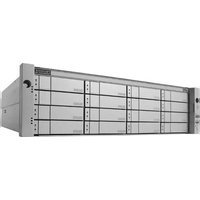
- Vess R2000 Series Product Manual
- Warning
- Caution
- Important
- Note
- Introduction 1
- System Setup 66
- WebPAM PROe - System Configuration 92
- NAS Function and Management 251
- Managing with the CLI 299
- Manage with CLU 410
- Technology Background 550
- Troubleshooting 603
- Contacting Technical Support 666
- Appendix: Useful Information 674
- INTRODUCTION
- ABOUT THIS MANUAL
- Vess R2600 OVERVIEW
- PERFORMANCE
- VERSATILITY
- SERVICE AND SUPPORT
- NOTABLE FEATURES IN THE VESS R2600
- PERFECTREBUILD™
- ADVANCED BATTERY FLASH BACKUP
- ONLINE LUN CLONE
- ARCHITECTURAL DESCRIPTION
- HARDWARE
- FRONT PANEL HARDWARE
- FRONT PANEL LEDs
- REAR PANEL HARDWARE
- REAR PANEL LEDs
- SYSTEM MANAGEMENT
- MANAGEMENT INTERFACES
- ADVANCED STORAGE FEATURES
- BACKGROUND ACTIVITIES
- PERFECTRAID FEATURES
- SUPPORTED BROWSERS
- NAS SHARED DISK FILE SYSTEM
- WARRANTY AND SUPPORT
- WARRANTY
- HARDWARE INSTALLATION
- UNPACKING
- PACKING LIST
- MOUNTING THE VESS ENCLOSURE IN A RACK
- Cautions
- INSTALLING PHYSICAL DRIVES
- NUMBER OF DRIVES REQUIRED
- DRIVE SLOT NUMBERING
- INSTALLING YOUR DRIVES
- MAKING MANAGEMENT AND DATA CONNECTIONS
- FIBRE CHANNEL SAN
- FC SAN DATA PATH
- To establish the data path:
- MANAGEMENT PATH
- FIBRE CHANNEL DAS
- FC DAS DATA PATH
- FIBRE CHANNEL WITH JBOD EXPANSION
- FIBRE CHANNEL SAN – No SINGLE POINT OF FAILURE
- FC SAN NSPF DATA PATH
- FC SAN NSPF MANAGEMENT PATH
- JBOD EXPANSION
- ISCSI STORAGE AREA NETWORK (SAN)
- ISCSI SAN DATA PATH
- ISCSI DIRECT ATTACHED STORAGE (DAS)
- DATA PATH
- ISCSI WITH JBOD EXPANSION
- MAKING SERIAL CABLE CONNECTIONS
- CONNECTING THE POWER
- LED BEHAVIOR
- REAR PANEL PSU & COOLING UNIT LEDs
- CONTROLLER LEDs
- CONTROLLER LED BEHAVIOR
- SYSTEM SETUP
- SETTING-UP THE SERIAL CONNECTION
- ABOUT IP ADDRESSES
- DEFAULT IP ADDRESSES
- CHOOSING DHCP OR A STATIC IP ADDRESS
- ACCESSING THE MAC ADDRESS IN THE CLI
- ACCESSING THE MAC ADDRESS IN THE CLU
- SETTING-UP WITH THE CLI
- MAKING SUBSYSTEM DATE AND TIME SETTINGS (CLI)
- VIRTUAL MANAGEMENT PORT SETTINGS (CLI)
- MAKING VIRTUAL MANAGEMENT PORT SETTINGS - AUTOMATICALLY (CLI)
- MAKING VIRTUAL MANAGEMENT PORT SETTINGS - MANUALLY UNDER IPv4 (CLI)
- Example:
- MAKING VIRTUAL MANAGEMENT PORT SETTINGS - MANUALLY UNDER IPv6 (CLI)
- MAINTENANCE MODE SETTINGS (CLI)
- MAKING MAINTENANCE MODE SETTINGS - AUTOMATICALLY (CLI)
- MAKING MAINTENANCE MODE SETTINGS - MANUALLY UNDER IPv4 (CLI)
- MAKING MAINTENANCE MODE SETTINGS - MANUALLY UNDER IPv6 (CLI)
- SETTING UP WITH WEBPAM PROE
- LOGGING INTO WEBPAM PROE
- CREATING DISK ARRAYS AND LOGICAL DRIVES
- Wizard
- Automatic
- Advanced
- Automatic configuration menu
- STEP 1 - DISK ARRAY CREATION
- Advanced configuration menu - select physical drives
- Advanced configuration - create logical drives
- STEP 2 - LOGICAL DRIVE CREATION
- Advanced configuration - create spare drives
- STEP 3 - SPARE DRIVE CREATION
- STEP 4 - SUMMARY
- ENABLING LUN MAPPING AND MASKING
- LOGGING OUT OF WEBPAM PROE
- USING WEBPAM PROE OVER THE INTERNET
- This chapter contains the following topics:
- CHOOSING THE DISPLAY LANGUAGE
- PERUSING THE INTERFACE
- - Dashboard tab
- - Device tab
- - Storage tab
- - Administration tab
- VIEWING THE STORAGE NETWORK
- LOGGING ONTO A SUBSYSTEM
- FILTERING THE SUBSYSTEM LIST
- REFRESHING THE LIST
- MANAGING SUBSYSTEMS
- Subsystem management includes:
- VIEWING SUBSYSTEM INFORMATION
- MAKING SUBSYSTEM SETTINGS
- LOCKING OR UNLOCKING THE SUBSYSTEM
- SETTING THE LOCK
- RESETTING THE LOCK
- RELEASING THE LOCK
- RELEASING A LOCK SET BY ANOTHER USER
- RESTORING FACTORY DEFAULT SETTINGS
- Factory Default Settings (by type)
- Firmware Software NAS
- CLEARING STATISTICS
- SAVING A SERVICE REPORT
- IMPORTING A CONFIGURATION SCRIPT
- EXPORTING A CONFIGURATION SCRIPT
- RESTARTING THE SUBSYSTEM
- SHUTTING DOWN THE SUBSYSTEM
- RESTARTING THE SUBSYSTEM AFTER A SHUTDOWN
- MANAGING RAID CONTROLLERS
- RAID controller management includes:
- VIEWING CONTROLLER INFORMATION
- Click the Advanced Information tab.
- MAKING CONTROLLER SETTINGS
- Make settings changes as required:
- Click the Save button.
- Notes
- VIEWING CONTROLLER STATISTICS
- LOCATING A CONTROLLER
- VIEWING THE FLASH IMAGE INFORMATION
- UPDATING FIRMWARE ON A RAID SUBSYSTEM
- AUTOMATIC RESTART
- VIEWING BATTERY INFORMATION
- RECONDITIONING A BATTERY
- To recondition a battery immediately:
- MAKING SCHEDULE CHANGES
- BUZZER SETTINGS
- MANAGING ENCLOSURES
- VIEWING ENCLOSURE TOPOLOGY
- VIEWING THE ENCLOSURES SUMMARY
- VIEWING ENCLOSURE INFORMATION
- MAKING ENCLOSURE SETTINGS
- VIEWING FRU VPD INFORMATION
- VIEWING POWER SUPPLY STATUS
- VIEWING COOLING UNIT STATUS
- VIEWING TEMPERATURE SENSOR STATUS
- VIEWING VOLTAGE SENSOR STATUS
- MANAGING UPS UNITS
- VIEWING A LIST OF UPS UNITS
- MAKING UPS SETTINGS
- USB
- VIEWING UPS INFORMATION
- MANAGING NETWORK CONNECTIONS
- MAKING VIRTUAL MANAGEMENT PORT SETTINGS
- MAKING MAINTENANCE MODE SETTINGS
- MANAGING USERS
- User management includes:
- VIEWING USER INFORMATION
- To view user information:
- CREATING A USER
- MAKING USER SETTINGS
- CHANGING USER PASSWORDS
- DELETING A USER
- SETTING USER EVENT SUBSCRIPTIONS
- IMPORTING A USER DATABASE
- EXPORTING A USER DATABASE
- MANAGING BACKGROUND ACTIVITIES
- VIEWING CURRENT BACKGROUND ACTIVITIES
- VIEWING SCHEDULED BACKGROUND ACTIVITIES
- Adding a Scheduled Background Activity
- CHANGING A BACKGROUND ACTIVITY SCHEDULE
- ENABLING OR DISABLING A SCHEDULED BACKGROUND ACTIVITY
- DELETING A SCHEDULED BACKGROUND ACTIVITY
- MEDIA PATROL
- MAKING MEDIA PATROL SETTINGS
- REDUNDANCY CHECK
- MAKING REDUNDANCY CHECK SETTINGS
- INITIALIZATION
- MAKING INITIALIZATION SETTINGS
- REBUILD
- MAKING REBUILD SETTINGS
- MIGRATION
- MAKING MIGRATION SETTINGS
- PDM
- MAKING PDM SETTINGS
- TRANSITION
- MAKING TRANSITION SETTINGS
- SYNCHRONIZATION
- MAKING SYNCHRONIZATION SETTINGS
- BATTERY RECONDITIONING
- MANAGING STORAGE SERVICES
- VIEWING A LIST OF SERVICES
- EMAIL SERVICE
- STOPPING EMAIL SERVICE
- RESTARTING EMAIL SERVICE
- MAKING EMAIL SETTINGS
- TELNET SERVICE
- STOPPING TELNET SERVICE
- RESTARTING TELNET SERVICE
- MAKING TELNET SETTINGS
- SSH SERVICE
- STOPPING SSH SERVICE
- RESTARTING SSH SERVICE
- MAKING SSH SETTINGS
- SNMP SERVICE
- STOPPING SNMP SERVICE
- RESTARTING SNMP SERVICE
- MAKING SNMP SETTINGS
- To change SNMP service settings:
- ADDING AN SNMP TRAP SINK
- DELETING AN SNMP TRAP SINK
- To delete a trap sink:
- NETSEND SERVICE
- STARTING NETSEND SERVICE
- STOPPING NETSEND
- RESTARTING NETSEND SERVICE
- MAKING NETSEND SETTINGS
- Adding Netsend Server Accounts
- DELETING NETSEND SERVER ACCOUNTS
- WORKING WITH THE EVENT VIEWER
- VIEWING RUNTIME EVENTS
- To display Runtime Events:
- SAVING RUNTIME EVENTS
- CLEARING RUNTIME EVENTS
- VIEWING NVRAM EVENTS
- SAVING NVRAM EVENTS
- CLEARING NVRAM EVENTS
- MONITORING PERFORMANCE
- MONITORING I/O PERFORMANCE
- Logical Drive
- Physical Drive
- Port
- NAS
- MONITORING PSU WATTAGE
- MANAGING PHYSICAL DRIVES
- VIEWING A LIST OF PHYSICAL DRIVES
- VIEWING PHYSICAL DRIVE INFORMATION
- Click the physical drive you want, then click the View button.
- Advanced information for SATA physical drives includes:
- MAKING GLOBAL PHYSICAL DRIVE SETTINGS
- MAKING INDIVIDUAL PHYSICAL DRIVE SETTINGS
- VIEWING PHYSICAL DRIVE STATISTICS
- VIEWING PHYSICAL DRIVE SMART LOG INFORMATION
- SAVING THE PHYSICAL DRIVE SMART LOG
- LOCATING A PHYSICAL DRIVE
- CLEARING A STALE OR A PFA CONDITION
- UPDATING FIRMWARE ON A PHYSICAL DRIVE
- MANAGING DISK ARRAYS
- VIEWING A LIST OF DISK ARRAYS
- VIEWING DISK ARRAY INFORMATION
- DISK ARRAY OPERATIONAL STATUS
- CREATING A DISK ARRAY MANUALLY
- CREATING A DISK ARRAY WITH THE WIZARD
- DELETING A DISK ARRAY
- MAKING DISK ARRAY SETTINGS
- RUNNING MEDIA PATROL ON A DISK ARRAY
- STOPPING, PAUSING OR RESUMING MEDIA PATROL
- RUNNING PDM ON A DISK ARRAY
- RUNNING PDM
- STOPPING, PAUSING OR RESUMING PDM
- PREPARING A DISK ARRAY FOR TRANSPORT
- REBUILDING A DISK ARRAY
- PERFORMING A MANUAL REBUILD
- STOPPING, PAUSING OR RESUMING A REBUILD
- MANAGING LOGICAL DRIVES
- Logical drive management includes:
- VIEWING A LIST OF LOGICAL DRIVES
- VIEWING LOGICAL DRIVE INFORMATION
- Click the logical drive you want, then click the View button.
- VIEWING LOGICAL DRIVE STATISTICS
- VIEWING LOGICAL DRIVE CHECK TABLES
- CREATING A LOGICAL DRIVE MANUALLY
- DELETING A LOGICAL DRIVE
- MAKING LOGICAL DRIVE SETTINGS
- LOCATING A LOGICAL DRIVE
- INITIALIZING A LOGICAL DRIVE
- STOPPING, PAUSING OR RESUMING AN INITIALIZATION
- REDUNDANCY CHECK ON A LOGICAL DRIVE
- STOPPING, PAUSING OR RESUMING A REDUNDANCY CHECK
- MIGRATING A LOGICAL DRIVE'S RAID LEVEL
- MIGRATING A LOGICAL DRIVE
- CREATING A LUN CLONE
- LUN CLONE OPTIONS
- MANAGING SPARE DRIVES
- Spare drive management includes:
- VIEWING A LIST OF SPARE DRIVES
- To view a list of spare drives:
- VIEWING SPARE DRIVE INFORMATION
- CREATING A SPARE DRIVE MANUALLY
- DELETING A SPARE DRIVE
- MAKING SPARE DRIVE SETTINGS
- LOCATING A SPARE DRIVE
- RUNNING SPARE CHECK
- RUNNING A TRANSITION ON A SPARE DRIVE
- RUNNING A TRANSITION
- STOPPING, PAUSING OR RESUMING A TRANSITION
- MANAGING INITIATORS
- VIEWING A LIST OF INITIATORS
- Adding an FC Initiator
- METHOD 1: INPUTTING THE INITIATOR NAME
- METHOD 2: ADDING FROM A LIST
- DELETING AN FC INITIATOR
- Adding an ISCSI INITIATOR
- MANAGING LUNs
- VIEWING A LIST OF LUN MAPS
- LUN MAPPING AND MASKING
- Adding a LUN Map
- EDITING A LUN MAP
- DELETING A LUN MAP
- ENABLING AND DISABLING LUN MASKING
- MANAGING FIBRE CHANNEL CONNECTIONS
- VIEWING FC NODE INFORMATION
- VIEWING FC PORT INFORMATION
- MAKING FC PORT SETTINGS
- PORT SETTING INFORMATION
- VIEWING FC PORT STATISTICS
- VIEWING A LIST OF FC INITIATORS ON THE FABRIC
- VIEWING A LIST OF FC LOGGED-IN DEVICES
- VIEWING A LIST OF FC SFPs
- MANAGING ISCSI CONNECTIONS
- iSCSI management includes:
- VIEWING A LIST OF ISCSI TARGETS
- VIEWING ISCSI TARGET INFORMATION
- Target information includes:
- MAKING ISCSI TARGET SETTINGS
- To make target settings:
- VIEWING A LIST OF ISCSI PORTALS
- To view a list of iSCSI portals:
- Portal information includes:
- VIEWING ISCSI PORTAL INFORMATION
- Adding ISCSI PORTALS
- MAKING ISCSI PORTAL SETTINGS
- To make iSCSI portal settings:
- Click theSubmit button.
- DELETING ISCSI PORTALS
- To delete an iSCSI portal:
- VIEWING A LIST OF ISCSI PORTS
- VIEWING ISCSI PORT INFORMATION
- To view information about a port:
- MAKING ISCSI PORT SETTINGS
- VIEWING A LIST OF ISCSI TRUNKS
- Adding ISCSI TRUNKS
- MAKING ISCSI TRUNK SETTINGS
- To make trunk settings:
- DELETING ISCSI TRUNKS
- VIEWING A LIST OF ISCSI SESSIONS
- VIEWING ISCSI SESSION INFORMATION
- Information includes:
- DELETING AN ISCSI SESSION
- VIEWING ISCSI ISNS INFORMATION
- MAKING |SCSI |SNS SETTINGS
- To make iSNS settings:
- Click the Submit button.
- VIEWING A LIST OF ISCSI CHAPs
- To view a list of iSCSI CHAPs:
- Adding ISCSI CHAPs
- MAKING ISCSI CHAP SETTINGS
- DELETING ISCSI CHAPs
- PINGING A HOST OR SERVER ON THE ISCSI NETWORK
- NAS FUNCTION AND MANAGEMENT
- NAS FEATURE OVERVIEW
- PLANNING CONSIDERATIONS FOR NAS AND SAN SETUP
- NETWORK CABLING FOR NAS
- NAS CONFIGURATION
- FILE SYSTEM
- CREATE A DISK POOL
- To create a Disk Pool:
- EXTEND A DISK POOL
- CREATE A SHARE DISK
- CREATE HOME SHARE DISK
- Disk Pool Transport
- EXPORT NAS SETTINGS FOR TRANSPORT
- TRANSPORT DISK POOL
- RESCAN DISK POOL
- IMPORT NAS SETTINGS FOR TRANSPORTED DISK POOL
- SET USER QUOTAS
- MOUNT ISO IMAGE
- CREATE A NAS PORTAL
- WHAT IS A NAS PORTAL?
- CABLING AND PORTAL SETTING FOR NAS AND ISCSI
- BASIC NETWORK CABLING AND PORT CONFIGURATION FOR NAS AND ISCSI
- REDUNDANT PORT CONFIGURATION FOR NAS AND ISCSI
- ADVANCED REDUNDANCY NETWORK CABLING AND PORT CONFIGURATION
- BACKUP
- BACKUP SERVER SETTINGS
- ALLOW IP FOR BACKUP
- BACKUP SERVER PORT SETTINGS
- REPLICATION BACKUP
- Create Replication Backup menu
- RUN REPLICATION BACKUP
- REMOVE A REPLICATION BACKUP
- REPLICATION RECOVERY
- FILE BACKUP/RESTORE
- For File Backup:
- For File Restore:
- RUN FILE BACKUP
- RESTORE FILE BACKUP
- REMOVE FILE BACKUP
- SHARE DISK CLONE
- RUN SHARE DISK CLONE
- ACCOUNT MANAGEMENT
- To View Local User Information
- To input Local User Information
- To remove a Local User
- Add Local Users
- TO ADD A SINGLE LOCAL USER FOR THE NAS
- TO ADD A MULTIPLE LOCAL USERS FOR THE NAS
- To remove Multiple Users from the Local Users List
- To Import Users to the Local Users List
- NAS GROUP SETTINGS
- USING THE NAS GROUP LIST
- To View Group Members
- Add Local Group and Choose Local User MEMBERS
- To Join a Domain
- To Leave a Domain
- To Set a Workgroup
- To Refresh Domain Data
- PERMISSION SETTING
- To Display Permission Settings
- To Set Default Permission for Share Disk
- To Set Permission for Users or Groups
- MISCELLANEOUS
- BACKUP/RESTORE SETTINGS
- RESET NAS SETTINGS
- NAS EVENTS
- Clear/Save NAS Events log
- MANAGING WITH THE CLI
- MAKING A SERIAL CONNECTION
- LOGGING INTO THE CLI
- CLI administrator prompt
- TABLE OF SUPPORTED COMMANDS
- NOTES AND CONVENTIONS
- about
- Usage
- Summary
- array
- Options
- assn
- battery
- bbm
- Examples
- bga
- bgasched
- buzz
- chap
- checktable
- clone
- config
- ctrl
- date
- enclosure
- event
- export
- factorydefaults
- fc
- import
- init
- initiator
- iscsi
- isns
- lunmap
- logdrv
- logout
- migrate
- net
- ntp
- password
- phydrv
- ping
- ptiflash
- rc
- rb
- sas
- sasdiag
- sc
- scsi
- session
- shutdown
- smart
- spare
- stats
- subsys
- swmgt
- sync
- topology
- trunk
- transit
- ups
- user
- zoning
- help
- ?
- menu
- MANAGE WITH CLU
- This chapter covers the following topics:
- INITIAL CONNECTION
- MAKING A TELNET CONNECTION
- MAKING A SSH CONNECTION
- WINDOWS
- LINUX
- CLU main menu
- ACCESSING ONLINE HELP
- EXITING THE CLU
- LOGGING OUT OF THE CLI
- LOGGING BACK INTO THE CLI AND CLU
- MANAGING THE SUBSYSTEM (CLU)
- MAKING SUBSYSTEM SETTINGS (CLU)
- RUNNING MEDIA PATROL (CLU)
- LOCKING OR UNLOCKING THE SUBSYSTEM (CLU)
- SETTING SUBSYSTEM DATE AND TIME (CLU)
- MAKING NTP SETTINGS (CLU)
- SYNCHRONIZING WITH A NTP SERVER (CLU)
- MANAGING THE RAID CONTROLLERS (CLU)
- VIEWING CONTROLLER INFORMATION (CLU)
- CLEARING AN ORPHAN WATERMARK (CLU)
- MAKING CONTROLLER SETTINGS (CLU)
- LOCATING THE CONTROLLER (CLU)
- MANAGING THE ENCLOSURE (CLU)
- VIEWING THE ENCLOSURES SUMMARY (CLU)
- VIEWING ENCLOSURE INFORMATION (CLU)
- To view enclosure information:
- ADJUSTABLE ITEMS
- MAKING ENCLOSURE SETTINGS (CLU)
- To make Enclosure settings:
- VIEWING FRU VPD INFORMATION (CLU)
- VIEWING POWER SUPPLY STATUS (CLU)
- LOCATING A POWER SUPPLY (CLU)
- To locate a power supply:
- VIEWING COOLING UNIT STATUS (CLU)
- To view the status of the power supply fans:
- VIEWING TEMPERATURE SENSOR STATUS (CLU)
- VIEWING VOLTAGE SENSOR STATUS (CLU)
- VIEWING BATTERY INFORMATION (CLU)
- BATTERY NOTES
- RECONDITIONING A BATTERY (CLU)
- LOCATING AN ENCLOSURE (CLU)
- VIEWING ENCLOSURE TOPOLOGY (CLU)
- PHYSICAL DRIVE MANAGEMENT (CLU)
- VIEWING A LIST OF PHYSICAL DRIVES (CLU)
- MAKING GLOBAL PHYSICAL DRIVE SETTINGS (CLU)
- VIEWING PHYSICAL DRIVE INFORMATION (CLU)
- VIEWING PHYSICAL DRIVE STATISTICS (CLU)
- SETTING AN ALIAS (CLU)
- CLEARING STALE AND PFA CONDITIONS (CLU)
- LOCATING A PHYSICAL DRIVE (CLU)
- MANAGING DISK ARRAYS (CLU)
- VIEWING A LIST OF DISK ARRAYS (CLU)
- CREATING A DISK ARRAY (CLU)
- CREATING A DISK ARRAY — AUTOMATIC (CLU)
- CREATING A DISK ARRAY — EXPRESS (CLU)
- CREATING A DISK ARRAY — ADVANCED (CLU)
- Step 1 – Disk Array Creation
- Step 2 – Logical Drive Creation
- Step 3 – Summary
- DELETING A DISK ARRAY (CLU)
- MAKING DISK ARRAY SETTINGS (CLU)
- VIEWING DISK ARRAY INFORMATION (CLU)
- ACCEPTING AN INCOMPLETE ARRAY (CLU)
- ENABLING MEDIA PATROL, PDM, POWER MANAGEMENT - DISK ARRAY (CLU)
- PREPARING THE DISK ARRAY FOR TRANSPORT (CLU)
- REBUILDING A DISK ARRAY (CLU)
- RUNNING MEDIA PATROL ON A DISK ARRAY (CLU)
- RUNNING PDM ON A DISK ARRAY (CLU)
- RUNNING TRANSITION ON A DISK ARRAY (CLU)
- LOCATING A DISK ARRAY (CLU)
- MANAGING SPARE DRIVES (CLU)
- VIEWING A LIST OF SPARE DRIVES (CLU)
- CREATING A SPARE DRIVE (CLU)
- MAKING SPARE DRIVE SETTINGS (CLU)
- To change spare drive settings:
- RUNNING SPARE CHECK (CLU)
- To run Spare Check:
- DELETING A SPARE DRIVE (CLU)
- To delete a spare drive:
- MANAGING LOGICAL DRIVES (CLU)
- CREATING A LOGICAL DRIVE (CLU)
- DELETING A LOGICAL DRIVE (CLU)
- VIEWING LOGICAL DRIVE INFORMATION (CLU)
- VIEWING LOGICAL DRIVE STATISTICS (CLU)
- VIEWING THE LOGICAL DRIVE CHECK TABLE (CLU)
- MAKING LOGICAL DRIVE SETTINGS (CLU)
- To make Logical Drive settings:
- INITIALIZING A LOGICAL DRIVE (CLU)
- RUNNING REDUNDANCY CHECK (CLU)
- LOCATING A LOGICAL DRIVE (CLU)
- MIGRATING A LOGICAL DRIVE (CLU)
- CREATING A LUN CLONE (CLU)
- MANAGING THE NETWORK CONNECTION (CLU)
- MAKING VIRTUAL MANAGEMENT PORT SETTINGS (CLU)
- MAKING AUTOMATIC SETTINGS
- MAKING MANUAL SETTINGS
- MAKING MAINTENANCE MODE SETTINGS (CLU)
- MANAGING FIBRE CHANNEL CONNECTIONS (CLU)
- VIEWING NODE INFORMATION (CLU)
- VIEWING FIBRE CHANNEL PORT INFORMATION
- VIEWING FIBRE CHANNEL LOGGED-IN DEVICES (CLU)
- MAKING FIBRE CHANNEL PORT SETTINGS (CLU)
- VIEWING FIBRE CHANNEL PORT STATISTICS (CLU)
- VIEWING SFP INFORMATION (CLU)
- PROPERTY DEFINITIONS
- VIEWING FIBRE CHANNEL INITIATORS (CLU)
- MANAGING ISCSI CONNECTIONS (CLU)
- VIEWING A LIST OF ISCSI TARGETS (CLU)
- VIEWING ISCSI TARGET INFORMATION (CLU)
- MAKING |SCSI TARGET SETTINGS (CLU)
- VIEWING A LIST OF ISCSI PORTS (CLU)
- VIEWING ISCSI PORT INFORMATION (CLU)
- MAKING ISCSI PORT SETTINGS (CLU)
- To make port settings:
- VIEWING A LIST OF ISCSI PORTALS (CLU)
- VIEWING ISCSI PORTAL INFORMATION (CLU)
- ADDING ISCSI PORTALS (CLU)
- MAKING ISCSI PORTAL SETTINGS (CLU)
- To make portal settings:
- DELETING ISCSI PORTALS (CLU)
- VIEWING A LIST OF ISCSI SESSIONS (CLU)
- To view a list of iSCSI sessions:
- DELETING AN ISCSI SESSION (CLU)
- VIEWING |SCSI SESSION INFORMATION (CLU)
- VIEWING |SCSI |SNS INFORMATION (CLU)
- MAKING |SCSI |SNS SETTINGS (CLU)
- VIEWING A LIST OF ISCSI CHAPs (CLU)
- ADDING |SCSI CHAPs (CLU)
- MAKING |SCSI CHAP SETTINGS (CLU)
- DELETING |SCSI CHAPs (CLU)
- PINGING A HOST OR SERVER ON THE ISCSI NETWORK (CLU)
- VIEWING A LIST OF ISCSI TRUNKS (CLU)
- ADDING | SCSI TRUNKS (CLU)
- MAKING |SCSI TRUNK SETTINGS (CLU)
- DELETING ISCSI TRUNKS (CLU)
- MANAGING BACKGROUND ACTIVITY
- MAKING BACKGROUND ACTIVITY SETTINGS
- WORKING WITH THE EVENT VIEWER (CLU)
- VIEWING RUNTIME EVENTS (CLU)
- CLEARING RUNTIME EVENTS (CLU)
- VIEWING NVRAM EVENTS (CLU)
- CLEARING NVRAM EVENTS (CLU)
- WORKING WITH LUN MAPPING (CLU)
- ENABLING LUN MAPPING (CLU)
- VIEWING A LIST OF INITIATORS (CLU)
- Adding an Initiator (CLU)
- DELETING AN INITIATOR (CLU)
- VIEWING A LIST OF LUN MAPS (CLU)
- ADDING A LUN MAP (CLU)
- MAPPING A LUN TO AN FC INITIATOR
- MAPPING A LUN TO AN ISCSI INITIATOR OR TARGET
- EDITING A LUN MAP (CLU)
- DELETING A LUN MAP (CLU)
- CHANGING THE ACTIVE LUN MAPPING TYPE (CLU)
- MANAGING UPS UNITS (CLU)
- VIEWING A LIST OF UPS UNITS (CLU)
- MAKING UPS SETTINGS (CLU)
- VIEWING UPS INFORMATION (CLU)
- MANAGING USERS (CLU)
- VIEWING USER INFORMATION (CLU)
- CREATING A USER (CLU)
- CHANGING ANOTHER USER'S SETTINGS (CLU)
- CHANGING YOUR OWN USER SETTINGS (CLU)
- CHANGING ANOTHER USER'S PASSWORD (CLU)
- CHANGING YOUR OWN PASSWORD (CLU)
- DELETING A USER (CLU)
- WORKING WITH SOFTWARE MANAGEMENT (CLU)
- MAKING EMAIL SETTINGS (CLU)
- MAKING SLP SETTINGS (CLU)
- MAKING TELNET SETTINGS (CLU)
- MAKING SSH SETTINGS (CLU)
- MAKING SNMP SETTINGS (CLU)
- MANAGING SNMP TRAP SINKS (CLU)
- VIEWING A LIST OF TRAP SINKS
- Adding a Trap Sink
- DELETING A TRAP SINK
- MAKING NETSEND SETTINGS (CLU)
- MANAGING NETSEND RECIPIENTS (CLU)
- NETSEND REQUIREMENTS
- Adding NETSEND RECIPIENTS
- DELETING NETSEND RECIPIENTS
- FLASHING THROUGH TFTP
- VIEWING FLASH IMAGE INFORMATION (CLU)
- CLEARING STATISTICS (CLU)
- RESTORING FACTORY DEFAULTS (CLU)
- SHUTTING DOWN THE SUBSYSTEM (CLU)
- SHUTTING DOWN THE ENCLOSURE — TELNET CONNECTION
- SHUTTING DOWN THE ENCLOSURE— SERIAL CONNECTION
- STARTING UP AFTER SHUTDOWN
- STARTING UP THE ENCLOSURE — TELNET CONNECTION
- STARTING UP THE ENCLOSURE — SERIAL CONNECTION
- RESTARTING THE ENCLOSURE - TELNET CONNECTION
- RESTARTING THE ENCLOSURE — SERIAL CONNECTION
- To restart the RAID subsystem:
- BUZZER
- Making Buzzer Settings
- MAINTENANCE
- UPDATING THE SUBSYSTEM FIRMWARE
- UPDATING WITH WEBPAM PROE
- UPDATING WITH THE CLU
- UPDATING WITH USB SUPPORT
- FAILED UPDATE
- UPDATING PHYSICAL DRIVE FIRMWARE
- WEBPAM PROE
- RESTARTING A SUBSYSTEM
- REPLACING A POWER SUPPLY
- REMOVING THE OLD POWER SUPPLY
- INSTALLING A NEW POWER SUPPLYT
- REPLACING A COOLING UNIT
- To remove the Cooling Unit
- To insert a new Cooling Unit
- REPLACING A CACHE BACKUP BATTERY
- REPLACING A RAID CONTROLLER – DUAL CONTROLLERS
- INSTALLING THE NEW CONTROLLER
- REPLACING A RAID CONTROLLER – SINGLE CONTROLLER
- TECHNOLOGY BACKGROUND
- Disk Arrays
- LOGICAL DRIVES
- RAID LEVELS
- RAID 0 - STRIPE
- Recommended Applications for RAID 0:
- RAID 1 - MIRROR
- Recommended Applications for RAID 1:
- RAID 1E - ENHANCED MIRROR
- RAID 5 - BLOCK AND PARITY STRIPE
- RAID 6 - BLOCK AND DOUBLE PARITY STRIPE
- RAID 10 - MIRROR + STRIPE
- RAID 50 - STRIPING OF DISTRIBUTED PARITY
- RAID 50 Axles
- RAID 60 - STRIPING OF DOUBLE PARITY
- RAID 60 Axles
- RAID LEVEL MIGRATION
- MIGRATION REQUIREMENTS
- SOURCE AND TARGET RAID LEVELS
- RAID 0
- RAID 1
- RAID 1E
- RAID 5
- RAID 6
- RAID 10
- RAID 50
- RAID 60
- STRIPE SIZE
- SECTOR SIZE
- PREFERRED CONTROLLER ID
- PARTITION AND FORMAT
- SPARE DRIVES
- DEFINITION
- REQUIREMENTS
- Example
- Automatic Transition
- Manual Transition
- RAID CONTROLLERS
- LUN AFFINITY
- ALUA
- CACHE POLICY
- READ CACHE POLICY
- WRITE CACHE POLICY
- Forced Read-Ahead Cache
- ADAPTIVE WRITEBACK CACHE
- Advanced Battery Flash Backup is enabled or disabled:
- Host Cache Flushing
- POWER SAVING
- CAPACITY COERCION
- ISCSI MANAGEMENT
- BASIC ISCSI
- ISCSI ON A VLAN
- Software
- TARGET
- DIGESTS
- CHAPs
- PORTAL
- INTERNET PROTOCOLS
- TROUBLESHOOTING
- Vess R2000 is BEEPING
- LEDs DISPLAY AMBER OR RED
- LEDs on the Front of the Vess R2000
- DRIVE CARRIER LEDs
- LEDs ON THE BACK OF THE VESS R2000
- POWER SUPPLY LEDs
- CHECKING COMPONENT INSTALLATION
- CLU REPORTS A PROBLEM
- CHECKING A REPORTED COMPONENT
- WEBPAM PROE REPORTS A PROBLEM
- Header
- Dashboard Tab
- System Status
- DEVICE TAB
- STORAGE TAB
- ADMINISTRATION TAB
- USB SUPPORT REPORTS A PROBLEM
- ENCLOSURE PROBLEMS
- DIAGNOSING AN ENCLOSURE PROBLEM
- OVERHEATING
- POWER SUPPLIES
- POWER FAN FAILURE
- BATTERIES
- RAID CONTROLLER PROBLEMS
- MAINTENANCE MODE
- FINDING AND CORRECTING THE CAUSE OF THE PROBLEM
- External Checks
- Internal Checks
- TAKING A RAID CONTROLLER OUT OF MAINTENANCE MODE
- Serial Connection
- Telnet Connection
- UNSAVED DATA IN THE CONTROLLER CACHE
- PHYSICAL DRIVE PROBLEMS
- DISK ARRAY AND LOGICAL DRIVE PROBLEMS
- DISK ARRAY DEGRADED / LOGICAL DRIVE CRITICAL
- REPAIRING AN OFFLINE DISK ARRAY OR LOGICAL DRIVE
- Take no further corrective action until you have consulted with Technical Support!
- RAID 0 Logical Drives
- INCOMPLETE ARRAY
- CONNECTION PROBLEMS
- Connection problems include:
- SERIAL CONNECTIONS
- NETWORK CONNECTIONS
- FIBRE CHANNEL CONNECTIONS
- SAS CONNECTIONS
- Blocked Cable Connectors
- Faulty Cable
- Faulty Controller or I/O Module Connector
- BROWSER DOES NOT CONNECT TO WEBPAM PROE
- POWER CYCLING THE SUBSYSTEM
- EVENT NOTIFICATION RESPONSE
- CONTACTING TECHNICAL SUPPORT
- United States
- Australia
- EMEA
- Netherlands
- Austria
- France
- Germany
- Sweden
- Switzerland ITF
- Norway ITF
- Belguim
- Luxembourg
- United Kingdom
- Taiwan
- China
- Korea
- Hong Kong
- Singapore
- Japan
- LIMITED WARRANTY
- DISCLAIMER OF OTHER WARRANTIES
- YOUR RESPONSIBILITIES
- RETURNING THE PRODUCT FOR REPAIR
- APPENDIX: USEFUL INFORMATION
- SNMP MIB FILES
- Adding a Second RAID CONTROLLER
- INSTALLING A SECOND RAID CONTROLLER
- RAID CONTROLLER IN MAINTENANCE MODE
- NEW SETTINGS FOR DUAL CONTROLLERS
- DUAL CONTROLLERS AND SATA DRIVES
Brand : Promise Technology
Model : VESS J2600SS
Category : NAS