RPS600WA - Alimentation ordinateur Edge-Core - Free user manual and instructions
Find the device manual for free RPS600WA Edge-Core in PDF.

| Product Type | Redundant Power Supply |
| Brand | Edge-Core |
| Model | RPS600WA |
| Power Output | 600 W |
| Input Voltage | 100-240 V AC |
| Input Frequency | 50/60 Hz |
| Output Voltage | 12 V DC (typical) |
| Form Factor | 1U Rackmount |
| Dimensions (W x D x H) | 430 x 250 x 44 mm |
| Weight | 2.5 kg |
| Cooling | Built-in fan, variable speed |
| Redundancy Support | 1+1 redundant |
| Certifications | UL, CE, FCC |
| Operating Temperature | 0°C to 50°C |
| Storage Temperature | -20°C to 70°C |
| Safety Protections | Over-voltage, over-current, short-circuit |
| Installation | Rack mountable with included brackets |
| Maintenance | Hot-swappable modules |
| Compatibility | Edge-Core switches and servers |
| Warranty | 1 year limited |
Frequently Asked Questions - RPS600WA Edge-Core
User questions about RPS600WA Edge-Core
0 question about this device. Answer the ones you know or ask your own.
Ask a new question about this device
Download the instructions for your Alimentation ordinateur in PDF format for free! Find your manual RPS600WA - Edge-Core and take your electronic device back in hand. On this page are published all the documents necessary for the use of your device. RPS600WA by Edge-Core.
USER MANUAL RPS600WA Edge-Core
External Redundant Power Supply Installation Guide
Installation Guide
External Redundant Power Supply with 4 Independent Redundant Power Supply Ports
RPS600WA-38
E012005-R01
150000046600A
Compliances
FCC - Class B
This equipment generates, uses, and can radiate radio frequency energy and, if not installed and used in accordance with the instruction manual, may cause interference to radio communications. It has been tested and found to comply with the limits for a Class B computing device pursuant to Subpart B of Part 15 of FCC Rules, which are designed to provide reasonable protection against such interference when operated in a commercial environment. Operation of this equipment in a residential area is likely to cause interference, in which case the user, at his own expense, will be required to take whatever measures may be required to correct the interference. You are cautioned that changes or modifications not expressly approved by the party responsible for compliance could void your authority to operate the equipment.
Warnings: 1. Wear an anti-static wrist strap or take other suitable measures to prevent electrostatic discharge when handling this equipment.
- When connecting this hub to a power outlet, connect the field ground lead on the tri-pole power plug to a valid earth ground line to prevent electrical hazards.
Industry Canada - Class B
This digital apparatus does not exceed the Class A limits for radio noise emissions from digital apparatus as set out in the interference-causing equipment standard entitled "Digital Apparatus," ICES-003 of the Department of Communications.
CE Mark Declaration of Conformance for EMI and Safety (EEC)
This information technology equipment complies with the requirements of the Council Directive 89/336/EEC on the Approximation of the laws of the Member States relating to Electromagnetic Compatibility and 73/23/EEC for electrical equipment used within certain voltage limits and the Amendment Directive 93/68/EEC. For the evaluation of the compliance with these Directives, the following standards were applied:
RFI Emission: • Limit class A according to EN 55022:1998
- Limit class A for harmonic current emission according to EN 61000-3-2/1995
- Limitation of voltage fluctuation and flicker in low-voltage supply system according to EN 61000-3-3/1995
Immunity: • Product family standard according to EN 55024:1998
- Electrostatic Discharge according to EN 61000-4-2:1995
(Contact Discharge: ±4 kV, Air Discharge: ±8 kV) - Radio-frequency electromagnetic field according to EN 61000-4-3:1996 (80 - 1000 MHz with 1 kHz AM 80% Modulation: 3 V/m)
- Electrical fast transient/burst according to EN 61000-4-4:1995 (AC/DC power supply: ±1 kV, Data/Signal lines: ±0.5 kV)
- Immunity to conducted disturbances, Induced by radio-frequency fields: EN 61000-4-6:1996 (0.15 - 80 MHz with 1 kHz AM 80% Modulation: 3 V/m)
- Power frequency magnetic field immunity test according to EN 61000-4-8:1993
(1 A/m at frequency 50 Hz)
- Voltage dips, short interruptions and voltage variations immunity test according to EN 61000-4-11:1994 (>95% Reduction @10 ms, 30% Reduction @500 ms, >95% Reduction @5000 ms)
LVD: • EN 60950-1 :2000
Please read the following safety information carefully before installing the RPS:
WARNING: Installation and removal of the unit must be carried out by qualified personnel only.
- The unit must be connected to an earthed (grounded) outlet to comply with international safety standards.
- Do not connect the unit to an A.C. outlet (power supply) without an earth (ground) connection.
- The appliance coupler (the connector to the unit and not the wall plug) must have a configuration for mating with an EN 60320/IEC 320 appliance inlet.
- The socket outlet must be near to the unit and easily accessible. You can only remove power from the unit by disconnecting the power cord from the outlet.
- This unit operates under SELV (Safety Extra Low Voltage) conditions according to IEC 60950. The conditions are only maintained if the equipment to which it is connected also operates under SELV conditions.
France and Peru only
This unit cannot be powered from IT† supplies. If your supplies are of IT type, this unit must be powered by 230 V (2P+T) via an isolation transformer ratio 1:1, with the secondary connection point labelled Neutral, connected directly to earth (ground).
| Power Cord Set | |
| U.S.A. and Canada The cord set must be UL-approved and CSA certified. | |
| The cord set must have a rated current capacity of at least 10 A | |
| U.K. The supply plug must comply with BS1363 (3-pin 13 A) and be fitted with a 5 A fuse which complies with BS1362. | |
| Europe The supply plug must comply with CEE7/7 ("SCHUKO"). | |
Warnings and Cautionary Messages
Warning: This product does not contain any user serviceable parts.
Warning: Installation and removal of the unit must be carried out by qualified personnel only.
Warning: When connecting this device to a power outlet, connect the field ground lead on the tri-pole power plug to a valid earth ground line to prevent electrical hazards.
Caution: Wear an anti-static wrist strap or take other suitable measures to prevent electrostatic discharge when handling this equipment.
Warnings (in German)
Environmental Statement
The manufacturer of this product endeavours to sustain an environmentally-friendly policy throughout the entire production process. This is achieved though the following means:
- Adherence to national legislation and regulations on environmental production standards.
• Conservation of operational resources. - Waste reduction and safe disposal of all harmful un-recyclable by-products.
• Recycling of all reusable waste content. - Design of products to maximize recyclables at the end of the product's life span.
- Continual monitoring of safety standards.
End of Product Life Span
This product is manufactured in such a way as to allow for the recovery and disposal of all included electrical components once the product has reached the end of its life.
Manufacturing Materials
There are no hazardous nor ozone-depleting materials in this product.
Documentation
All printed documentation for this product uses biodegradable paper that originates from sustained and managed forests. The inks used in the printing process are non-toxic.
Purpose
This guide details the hardware features of the RPS600WA redundant power supply, including it's physical and performance-related characteristics, and how to install the unit.
Contents
Chapter 1: About the Redundant Power Supply 1-1
Overview 1-1
Features and Benefits 1-1
Front and Rear Panels 1-2
LEDs 1-2
Supported Switches 1-4
Chapter 2: Installing the Redundant Power Supply 2-1
Installation 2-1
Selecting a Site 2-1
Equipment Checklist 2-2
Package Contents 2-2
Optional Rack-Mounting Equipment 2-2
Mounting 2-2
Rack Mounting 2-2
Desktop or Shelf Mounting 2-4
Connecting Switches to the RPS 2-5
Appendix A: Troubleshooting A-1
| Diagnosing RPS Indicators A-1 | |
| Power and Cooling Problems | A-2 |
| Installation | A-2 |
Appendix B: Specifications B-1
Physical Characteristics B-1
Compliances B-2
Index
Tables
Table 1-1 Port Status LEDs 1-3
Table 1-2 System LEDs 1-3
Table 1-3 Supported Switch 1-4
Table A-1. Troubleshooting Chart A-1
Figures
Figure 1-1 Front and Rear Panels 1-2
Figure 1-2 LEDs 1-2
Figure 2-1. Attaching the Brackets 2-3
Figure 2-2. Installing the RPS in a Rack 2-3
Figure 2-3. Attaching the Adhesive Feet 2-4
Figure 2-4. Power Receptacle 2-5
Figure 2-5. RPS Supporting Four Switches 2-6
Figures
Chapter 1:
About the Redundant Power Supply
Overview
This External Redundant Power Supply (RPS) can supply 600 Watts of backup power to four switches in the event of an AC loss or failure of an internal power supply.
Features and Benefits
• Supports four switch units with 11.5 VDC outputs of up to 150 W.
- Indicator LEDs located on the front panel.
- RPS AC line cord can draw power from a different supply circuit.
- DC line cords provide backup power to attached devices.
- Thermal overload protection prevents the RPS from overheating if a thermal overload occurs.
• Over-voltage protection shuts down an output channel if the voltage exceeds a preset threshold. (12.3 V)
• Over-current protection shuts down the RPS if the output load exceeds a preset threshold. (14.5 A)
- Short-circuit protection prevents the RPS from being damaged from a short circuit on any output channel.
- The RPS will operate under a no-load condition.
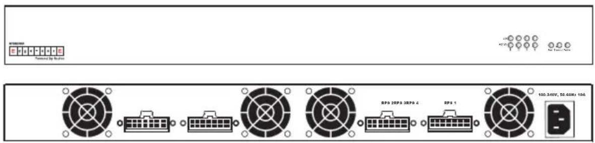
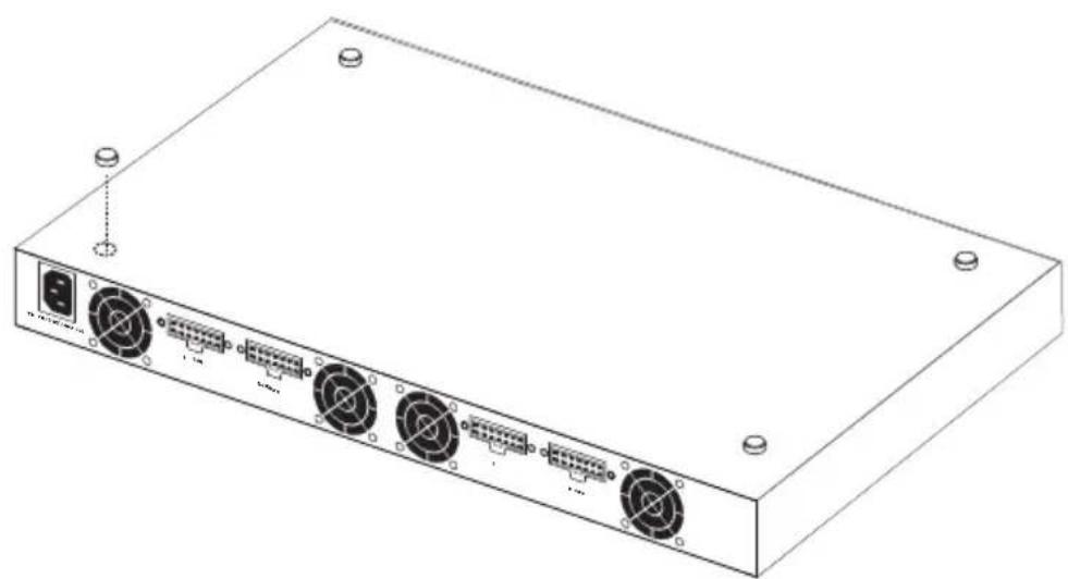
Front and Rear Panels
Four power indicators and one fan indicator are located on the RPS's front panel. While the AC supply and DC backup receptacles are located on the RPS's rear panel.
Figure 1-1 Front and Rear Panels
LEDs
The following diagram and tables describe the functions of the LEDs.
Figure 1-2 LEDs
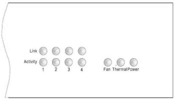
Table 1-1 Port Status LEDs
| LED (1-4) Condition Status | ||
| Link Off The port | does not have a valid connection to a switch. | |
| On Yellow The port | has a valid connection to a switch. | |
| Flashing Yellow There has been an RPS internal power failure. | ||
| Activity Off The port is not providing power to the connected switch. | ||
Table 1-2 System LEDs
| LED Condition | Status | |
| Fan On Green The fans are functioning normally. | ||
| Thermal On Green The temperature of the unit is within an acceptable range. | ||
| Power On Green AC power is being supplied to the RPS. | ||
Supported Switches
Table 1-3 Supported Switch
| Switches with 14-pin RPU connector on rear panel. |
| ES3526V |
| ES3526V 1 |
| ES3526VA |
| ES3526Y |
| ES3526YA |
| ES3550C |
| ES3550C 1 |
| ES3550YA |
| ES3628C |
| ES3652C |
| ES4512B |
| ES4524B |
| ES4524C |
| ES4548C |
| ES4525 |
| ES4549 |
| ES4612 |
| ES4624C |
| ES4625 |
| ES4649 |
Chapter 2:
Installing the Redundant Power Supply
Installation
The RPS may be placed on a desktop or mounted in a rack.
Caution: DO NOT place the RPS on the floor as the case is not waterproof. It is recommended that this RPS be installed in a network equipment rack.
Caution: Use only the RPS cables supplied with the unit. Using any other cables may damage the equipment.
Selecting a Site
RPS units can be mounted in a standard 19-inch equipment rack or on a flat surface. Be sure to follow the guidelines below when choosing a location.
- The site should:
- be at the center of all the devices you want to link and near a power outlet.
- be able to maintain its temperature within 0 to 45 °C (32 to 110 °F) and its humidity within 5% to 95%, non-condensing
• provide adequate space (approximately two inches) on all sides for proper air flow
- be accessible for installing, cabling and maintaining the devices
- allow the status LEDs to be clearly visible
- Make sure that a separate grounded power outlet that provides 100 to 240 VAC, 50-60 Hz, is within 2 m (6.56 feet) of each device and is powered from an independent circuit breaker. As with any equipment, using a filter or surge suppressor is recommended.
Equipment Checklist
After unpacking the RPS, check the contents to be sure you have received all the components. Then, before beginning the installation, be sure you have all other necessary installation equipment.
Package Contents
- Redundant Power Supply Unit
• One AC Supply Power Cord — US, Continental Europe or UK - Four DC Backup Power Cords with IEC connectors on both ends (length 152 cm each)
- Rack Mounting Kit containing brackets and screws
- Adhesive feet
- Registration Card
Optional Rack-Mounting Equipment
If you plan to rack-mount the RPS, be sure to have the following equipment available:
- Four mounting screws for each device you plan to install in a rack—these are not included
- A screwdriver (Phillips or flathead, depending on the type of screws used)
Mounting
RPS units can be mounted in a standard 19-inch equipment rack or on a desktop or shelf. Mounting instructions for each type of site follow.
Rack Mounting
Before rack mounting the unit, pay particular attention to the following factors:
- Temperature: Since the temperature within a rack assembly may be higher than the ambient room temperature, check that the rack-environment temperature is within the specified operating temperature range.
- Mechanical Loading: Do not place any equipment on top of a rack-mounted unit.
- Circuit Overloading: Be sure that the supply circuit to the rack assembly is not overloaded.
- Grounding: Rack-mounted equipment should be properly grounded. Particular attention should be given to supply connections other than direct connections to the mains.
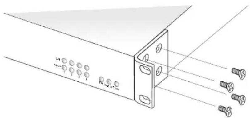
To rack-mount devices:
- Attach the brackets to the device using the screws provided in the Bracket Mounting Kit.
Figure 2-1. Attaching the Brackets
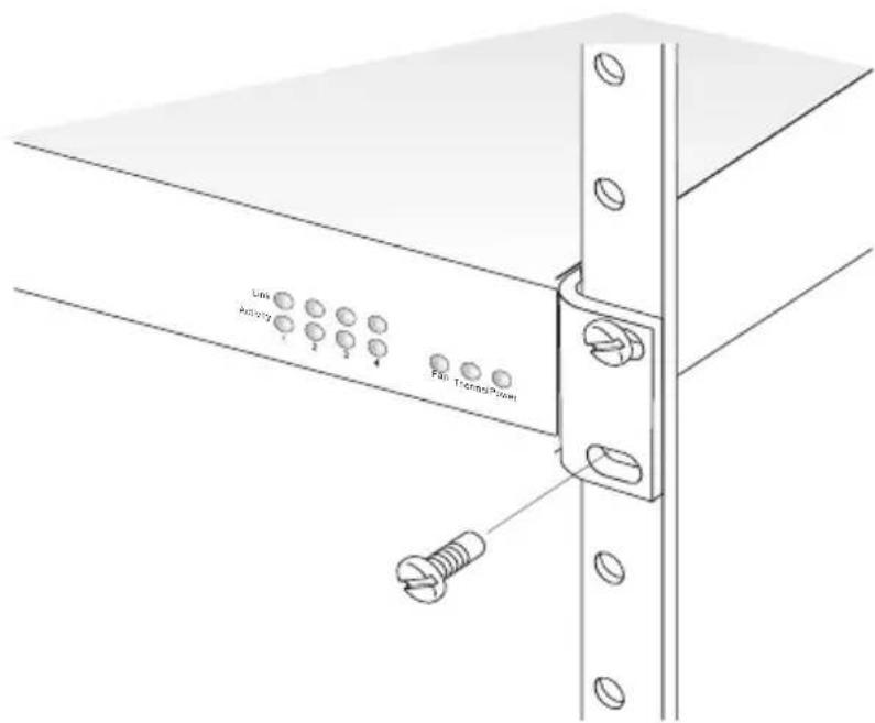
- Mount the device in the rack, using four rack-mounting screws (not provided).
Figure 2-2. Installing the RPS in a Rack
Montage (Rack Mounting Instructions - German)
Desktop or Shelf Mounting
- Attach the four adhesive feet to the bottom of the first RPS unit.
Figure 2-3. Attaching the Adhesive Feet
natural_image
Line drawing of a rectangular electronic device with multiple ports and connectors (no text or symbols)- Set the device on a flat surface near an AC power source, making sure there are at least two inches of space on all sides for proper air flow.
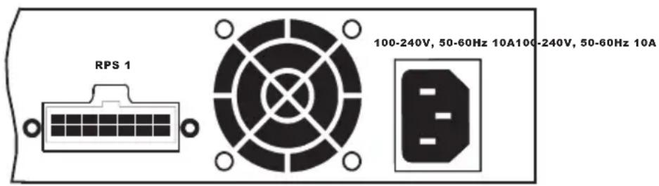
Connecting Switches to the RPS
Caution: DO NOT connect the RPS to an AC power source until DC power cords have been connected to the supported switches. Otherwise, the RPS may unnecessarily begin supplying backup power if the switch is not yet powered up.
To connect switches to the RPS:
- Connect one end of an AC cord to the AC receptacle on each supported switch, and the other end to a grounded power outlet. Connect the switches to a power mains that is separate from the RPS.
Figure 2-4. Power Receptacle
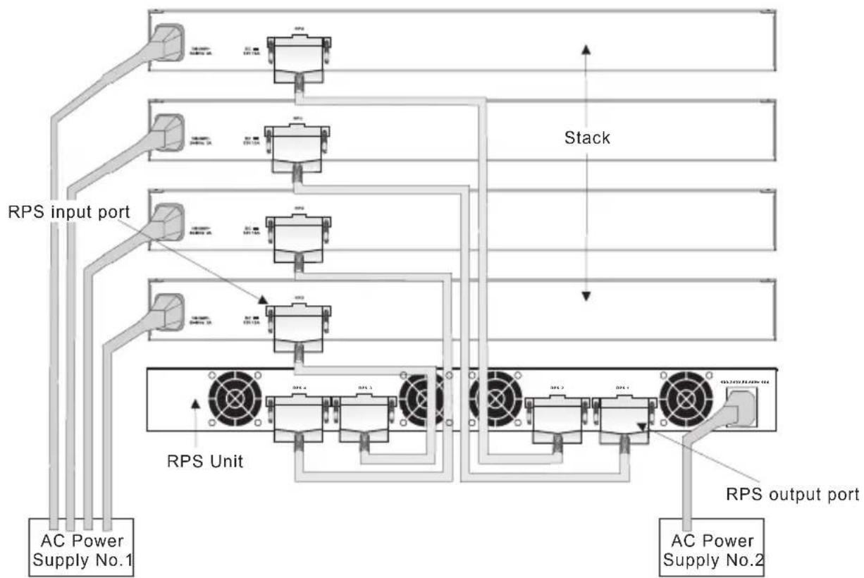
- Connect one end of a DC cord to the redundant power receptacle on the supported switch and the other end to an available receptacle on the RPS.
- Repeat steps 1 and 2 for connecting up to four supported switches to the RPS.
- Connect one end of the AC cord to the AC receptacle on the RPS, and the other end to a grounded power outlet.
- Check the LEDs on the RPS to ensure proper operation. The Link LEDs for connected switches should light up. If the LEDs indicate otherwise, see "Troubleshooting" on page A-1 for more information.
Figure 2-5. RPS Supporting Four Switches
flowchart
graph TD
    A["AC Power Supply No.1"] --> B["RPS Input Port"]
    B --> C["Stack"]
    C --> D["RPS Unit"]
    D --> E["Output Port"]
    style A fill:#f9f,stroke:#333
    style E fill:#bbf,stroke:#333
Note: For International use, you may need to change the AC line cord. You must use a line cord set that has been approved for the receptacle type in your country.
Diagnosing RPS Indicators
Table A-1. Troubleshooting Chart
| Symptom Action | |
| Power LED is Off • Internal power | supply is disconnected.• Check connections between the RPS, the power cord, and the wall outlet.• Contact Technical Support. |
| Link LED is Off • The port does not have a valid connection to a switch.• Check connections between the RPS and the switch.• Check that power is being supplied to the RPS. | |
| Link LED is Flashing Yellow • There has been an RPS internal power failure.• Contact Technical Support | |
| Activity LED is Flashing Green • The port has been shut down due to one of the following conditions:- The unit has detected an over-current condition.- One or more of the unit's fans have failed.• Check if the Fan LED is off, which indicates a fan failure.• Check that the attached switch does not require more than 150 W of power.• Power cycle the RPS to clear the condition.• If the condition persists, contact Technical Support. | |
| Fan LED is Flashing Yellow • One or more fans are not operating properly.• Replace the unit as soon as possible. | |
| Thermal LED is Flashing Yellow • Indicates a high temperature that is approaching an over-temperature condition.• Check that the unit's cooling fans are operating normally• Power off the RPS unit and allow to cool.• If the condition persists, contact Technical Support. | |
Power and Cooling Problems
If the PWR LED does not turn on when the power cord is plugged in, you may have a problem with the power outlet, power cord, or internal power supply. However, if the unit powers off after running for a while, check for loose power connections, power losses or surges at the power outlet, and verify that the fans on the unit are unobstructed and running prior to shutdown. If you still cannot isolate the problem, then the internal power supply may be defective. In this case, contact your distributor for assistance.
Installation
Verify that all system components have been properly installed. If one or more components appear to be malfunctioning (such as the power cord or RPS cable), test them in an alternate environment where you are sure that all the other components are functioning properly.
Physical Characteristics
Ports
4 RPS DC power outlets (IEC socket 216C743-07)
LEDs
Port: Link, Activity
System: Power, Fan, Thermal
Weight
5.5 kg (12.1 lbs)
Size
44.0 × 32.3 × 4.3 cm ( 17.34 × 12.6 × 1.69 in. )
Temperature
Operating: 0 to 45 °C (32 to 110°F)
Storage: -40 to 70 °C (-40 to 158 °F)
Humidity
Operating: 5% to 95%
AC Input
100 to 240 V, 50 to 60 Hz
DC Power Cable Connector
14-pin P-Type connector
Power Supply
Internal, auto-ranging transformer: 100 to 240 VAC, 50 to 60 Hz
Output 11.5 VDC
Power Consumption
644 W (Maximum)
161 W (Maximum per port)
Maximum Current
7.8 A @ 110 VAC
3.5 A @ 240 VAC
Overcurrent Protection
Ports are shutdown when output exceeds 14.5 A
Over-voltage Protection
Ports are shutdown when output exceeds 12.3 V
Power Supply
+11.5 VDC
Initial accuracy: +/- 1%
Current: 2 A (minimum), 10 A (maximum)
Line regulation: +/- 1%
Load regulation: +/- 10%
Overshoot and undershoot: 5%
Compliances
CE Mark
Emissions
FCC Class B
Industry Canada Class B
EN 55022 (CISPR 22) Class B
EN 61000-3-2/3
VCCI Class B
AS/NZS 3548 (1995) Class B
Immunity
EN 55024
Safety
CSA/CUS (CSA 60950-00 & UL60950)
CB: IE 60950
EN 60950 (TÜV/GS)
Index
A
adhesive feet, attaching 2-4 air flow requirements 2-1
B
brackets, attaching 2-3
C
compliances
EMC B-2
safety B-2
contents of package 2-2
cooling problems A-2
cord sets, international 2-6
D
desktop mounting 2-4
E
equipment checklist 2-2
F
front panel of RPS 1-2
G
grounding for racks 2-2
|
installation
desktop or shelf mounting 2-4
power requirements 2-1
problems A-2
rack mounting 2-2
site requirements 2-1
L
LED indicators
problems A-1
location requirements 2-1
M
mounting the RPS
in a rack 2-2
on a desktop or shelf 2-4
P
package contents 2-2
power, connecting to 2-5
problems, troubleshooting A-1
R
rack mounting 2-2
rear panel of RPS 1-2
rubber foot pads, attaching 2-4
S
screws for rack mounting 2-2
site selection 2-1
specifications
compliances B-2
environmental B-1
physical B-1
power B-1
standards
compliance B-2
IEEE B-2
surge suppressor, using 2-1
T
temperature within a rack 2-2
troubleshooting
in-band access A-2
power and cooling problems A-2
RPS indicators A-1