Redbox RB-PLI6 - Uncategorized Sonifex - Free user manual and instructions
Find the device manual for free Redbox RB-PLI6 Sonifex in PDF.

User questions about Redbox RB-PLI6 Sonifex
0 question about this device. Answer the ones you know or ask your own.
Ask a new question about this device
Download the instructions for your Uncategorized in PDF format for free! Find your manual Redbox RB-PLI6 - Sonifex and take your electronic device back in hand. On this page are published all the documents necessary for the use of your device. Redbox RB-PLI6 by Sonifex.
USER MANUAL Redbox RB-PLI6 Sonifex
RB-UL1 Single Stereo Unbalanced To Balanced Converters
RB-UL2 Dual Stereo Unbalanced To Balanced Converters
RB-UL4 Quad Stereo Unbalanced To Balanced Converters
RB-LU4 Quad Stereo Balanced To Unbalanced Converter
RB-BL2 Single Bi-Directional Matching Converter
RB-BL4 Dual Stereo Bi-Directional Matching Converter
RB-PA2 Dual Stereo RIAA Phono Amplifier
RB-LI2 Stereo Line Isolation Unit
RB-PLI6 6 Way Mono Passive Line Isolation Unit
Manufacturers of audio & video products for radio & TV broadcasters
SONIFEX
Redbox Handbook 3
For the latest Sonifex handbook information please visit the Sonifex website at www.sonifex.co.uk
Redbox User Handbook No 3
Stock Code: 30-339
Artwork: AW10833
Revision 3.02, March 2020
©Sonifex Ltd, 2020
All Rights Reserved
Sonifex Ltd, 61, Station Road, Irthlingborough,
Northants, NN9 5QE, England.
Tel: +44 (0)1933 650 700
Fax: +44 (0)1933 650 726
Email: sales@sonifex.co.uk
Website: https://www.sonifex.co.uk
Information in this document is subject to change without notice and does not represent a commitment on the part of the vendor. Sonifex Ltd shall not be liable for any loss or damage whatsoever arising from the use of information or any error contained in this manual.
No part of this manual may be reproduced or transmitted in any form or by any means, electronic or mechanical, including photocopying, recording, information storage and retrieval systems, for any purpose other than the purchaser's personal use, without the express written permission of Sonifex Ltd. Unless otherwise noted, all names of companies, products and persons contained herein are part of a completely fictitious adaptation and are designed solely to document the use of Sonifex product.
Made in the UK by SONIFEX
Contents
Contents
Product Warranty - 2 Year Extended ii
Sonifex Warranty & Liability Terms & Conditions ii
-
Definitions ii
-
Warranty ii
Unpacking Your Product iii
Repairs & Returns iv
€ Conformity iv
Safety & Installation of Mains Operated Equipment iv
Voltage Setting Checks iv
Fuse Rating iv
Power Cable & Connection iv
WEEE Directive v
Atmosphere/Environment v
Fitting Redboxes v
1 RB-UL1 Single Stereo Unbalanced To Balanced Converters 1
Introduction 1
System Block Diagram 1
Rear Panel Connections and Operation 1
Technical Specifications RB-UL1 2
2 RB-UL2 Dual Stereo Unbalanced To Balanced Converters 3
Introduction 3
System Block Diagram 3
Rear Panel Connections and Operation 3
Technical Specifications RB-UL2 4
3 RB-UL4 Quad Stereo Unbalanced To Balanced Converters 5
Introduction 5
System Block Diagram 5
Rear Panel Connections and Operation 5
Technical Specifications RB-UL4 6
4 RB-LU4 Quad Stereo Balanced To Unbalanced Converter 7
Introduction 7
System Block Diagram 8
Rear Panel Connections and Operation 9
Technical Specifications RB-LU4 9
5 RB-BL2 Single Bi-Directional Matching Converter 11
Introduction 11
System Block Diagram 11
Rear Panel Connections and Operation 12
Balanced to Unbalanced Connections 12
Unbalanced to Balanced Connections 12
Technical Specifications RB-BL2 13
6 RB-BL4 Dual Stereo Bi-Directional Matching Converter 14
Introduction 14
System Block Diagram 14
Rear Panel Connections and Operation 15
Balanced to Unbalanced Connections 15
Unbalanced to Balanced Connections 16
Technical Specifications RB-BL4 16
7 RB-PA2 Dual Stereo RIAA Phono Amplifier 17
Introduction 17
System Block Diagram 17
Rear Panel Connections and Operation 18
Technical Specifications RB-PA2 19
8 RB-LI2 Stereo Line Isolation Unit 20
Introduction 20
System Block Diagram 20
Rear Panel Connections and Operation 21
Technical Specifications RB-LI2 22
9 RB-PLI6 6 Way Mono Passive Line Isolation Unit 23
Introduction 23
System Block Diagram 23
Rear Panel Connections and Operation 24
Technical Specifications RB-PLI6 25
Figures
Figures
Fig A: RB-RK1 Small Redbox Front Rack-mount Kit . v
Fig B: RB-RK2 Small Redbox Rear Rack-mount Kit. vi
Fig C: RB-RK3 Large Redbox Rear Rack-mount Kit. vi
Fig 1-1: RB-UL1 Front Panel 1
Fig 1-2: RB-UL1 System Block Diagram 1
Fig 1-3: RB-UL1 Rear Panel 2
Fig 2-1: RB-UL2 Front Panel 3
Fig 2-2: RB-UL2 System Block Diagram 3
Fig 2-3: RB-UL2 Rear Panel 4
Fig 3-1: RB-UL4 Front Panel 5
Fig 3-2: RB-UL4 System Block Diagram 5
Fig 3-3: RB-UL4 Rear Panel 6
Fig 4-1: RB-LU4 Front Panel 7
Fig 4-2: RB-LU4 System Block Diagram 8
Fig 4-3: RB-LU4 Rear Panel 9
Fig 5-1: RB-BL2 Front Panel 11
Fig 5-2: RB-BL2 System Block Diagram 11
Fig 5-3: RB-BL2 Rear Panel 12
Fig 6-1: RB-BL4 Front Panel 14
Fig 6-2: RB-BL4 System Block Diagram 14
Fig 6-3: RB-BL4 Rear Panel 15
Fig 7-1: RB-PA2 Front Panel 17
Fig 7-2: RB-PA2 System Block Diagram For a Single
Stereo Channel 17
Fig 7-3: RB-PA2 Rear Panel 18
Fig 8-1: RB-LI2 Front Panel. 20
Fig 8-2: RB-LI2 System Block Diagram 20
Fig 8-3: RB-LI2 Rear Panel 21
Fig 8-4: RB-LI2 Jumper Positions on the PCB 22
Fig 9-1: RB-PLI6 Front Panel 23
Fig 9-2: RB-PLI6 System Block Diagram 23
Fig 9-3: RB-PLI6 Rear Panel 24
Fig 9-4: RB-PLI6 Ground-link Jumper Settings 24
SONIFEX
Register Online for an Extended 2 Year Warranty
As standard, Sonifex products are supplied with a 1 year back to base warranty.
If you register the product online, you can increase your product warranty to 2 years and we can also keep you informed of any product design improvements or modifications.
Product:
Serial No: ____
To register your product, please go online to www.sonifex.co.uk/register
Warranty
Product Warranty - 2 Year Extended
As standard, Sonifex products are supplied with a 1 year back to base warranty. In order to register the date of purchase and so that we can keep you informed of any product design improvements or modifications, it is important to complete the warranty registration online. Additionally, if you register the product on the Sonifex website, you can increase your product warranty to 2 years. Go to the Sonifex website at: https://www.sonifex.co.uk/technical/register/index.asp to apply for your 2 year warranty.
Note: For your own records the product serial number is recorded on the CE certification page of this handbook.
Sonifex Warranty & Liability Terms & Conditions
1. Definitions
'the Company' means Sonifex Ltd and where relevant includes companies within the same group of companies as Sonifex Limited.
'the Goods' means the goods or any part thereof supplied by the Company and where relevant includes: work carried out by the Company on items supplied by the Purchaser; services supplied by the Company; and software supplied by the Company.
'the Purchaser' means the person or organisation who buys or has agreed to buy the Goods.
'the Price' means the Price of the Goods and any other charges incurred by the Company in the supply of the Goods.
'the Warranty Term' is the length of the product warranty which is usually 12 months from the date of despatch; except when the product has been registered at the Sonifex website when the Warranty Term is 24 months from the date of despatch.
'the Contract' means the quotation, these Conditions of Sale and any other document incorporated in a contract between the Company and the Purchaser.
This is the entire Contract between the parties relating to the subject matter hereof and may not be changed or terminated except in writing in accordance with the provisions of this Contract. A reference to the consent, acknowledgement, authority or agreement of the Company means in writing and only by a director of the Company.
2. Warranty
a. The Company agrees to repair or (at its discretion) replace Goods which are found to be defective (fair wear and tear excepted) and which are returned to the Company within the Warranty Term provided that each of the following are satisfied:
i. notification of any defect is given to the Company immediately upon its becoming apparent to the Purchaser;
ii. the Goods have only been operated under normal operating conditions and have only been subject to normal use (and in particular the Goods must have been correctly connected and must not have been subject to high voltage or to ionising radiation and must not have been used contrary to the Company's technical recommendations);
iii. the Goods are returned to the Company's premises at the Purchaser's expense;
iv. any Goods or parts of Goods replaced shall become the property of the Company;
v. no work whatsoever (other than normal and proper maintenance) has been carried out to the Goods or any part of the Goods without the Company's prior written consent;
Warranty
vi. the defect has not arisen from a design made, furnished or specified by the Purchaser;
vii. the Goods have been assembled or incorporated into other goods only in accordance with any instructions issued by the Company;
viii. the defect has not arisen from a design modified by the Purchaser;
ix. the defect has not arisen from an item manufactured by a person other than the Company. In respect of any item manufactured by a person other than the Company, the Purchaser shall only be entitled to the benefit of any warranty or guarantee provided by such manufacturer to the Company.
b. In respect of computer software supplied by the Company the Company does not warrant that the use of the software will be uninterrupted or error free.
c. The Company accepts liability:
(i) for death or personal injury to the extent that it results from the negligence of the Company, its employees (whilst in the course of their employment) or its agents (in the course of the agency);
(ii) for any breach by the Company of any statutory undertaking as to title, quiet possession and freedom from encumbrance.
d. Subject to conditions (a) and (c) from the time of despatch of the Goods from the Company's premises the Purchaser shall be responsible for any defect in the Goods or loss, damage, nuisance or interference whatsoever consequential economic or otherwise or wastage of material resulting from or caused by or to the Goods. In particular the Company shall not be liable for any loss of profits or other economic losses. The Company accordingly excludes all liability for the same.
e. At the request and expense of the Purchaser the Company will test the Goods to ascertain performance levels and provide a report of the results of that test. The report will be accurate at the time of the test, to the best of the belief and knowledge of the Company, and the Company accepts no liability in respect of its accuracy beyond that set out in Condition (a).
f. Subject to Condition (e) no representation, condition, warranty or other term, express or implied (by statute or otherwise) is given by the Company that the Goods are of any particular quality or standard or will enable the Purchaser to attain any particular performance or result, or will be suitable for any particular purpose or use under specific conditions or will provide any particular capacity, notwithstanding that the requirement for such performance, result or capacity or that such particular purpose or conditions may have been known (or ought to have been known) to the Company, its employees or agents.
g. (i) To the extent that the Company is held legally liable to the Purchaser for any single breach of contract, tort, representation or other act or default, the Company's liability for the same shall not exceed the price of the Goods.
(ii) The restriction of liability in Condition (g)(i) shall not apply to any liability accepted by the Seller in Condition (c).
h. Where the Goods are sold under a consumer transaction (as defined by the Consumer Transactions (Restrictions on Statements) Order 1976) the statutory rights of the Purchaser are not affected by these Conditions of Sale.
Unpacking Your Product
Each product is shipped in protective packaging and should be inspected for damage before use. If there is any transit damage take pictures of the product packaging and notify the carrier immediately with all the relevant
CE Conformity
details of the shipment. Packing materials should be kept for inspection and also for if the product needs to be returned.
The product is shipped with the following equipment so please check to ensure that you have all of the items below. If anything is missing, please contact the supplier of your equipment immediately.
Item
Quantity
Product unit 1
IEC mains lead fitted with moulded mains plug 1
Handbook and warranty card 1
If you require a different power lead, please let us know when ordering the product.
Repairs & Returns
Please contact Sonifex or your supplier if you have any problems with your Sonifex product. Email technical.support@sonifex.co.uk for the repair/ upgrade/returns procedure, or for support & questions regarding the product operation.
CE Conformity
The products in this manual comply with the essential requirements of the relevant European health, safety and environmental protection legislation.
The technical justification file for this product is available at Sonifex Ltd.
The declaration of conformity can be found at: https://www.sonifex.co.uk/declarations
Safety & Installation of Mains Operated Equipment
There are no user serviceable parts inside the equipment. If you should ever need to look inside the unit, always disconnect the mains supply before removing the equipment covers. The cover is connected to earth by means of the fixing screws. It is essential to maintain this earth/ground connection to ensure a safe operating environment and provide electromagnetic shielding.
Voltage Setting Checks
Ensure that the machine operating voltage is correct for your mains power supply by checking the box in which your product was supplied. The voltage is shown on the box label. The available voltage settings are 115V, or 230V. Please note that all products are either switchable between 115V and 230V, or have a universal power supply.
Fuse Rating
The product is supplied with a single fuse in the live conducting path of the mains power input. For reasons of safety it is important that the correct rating and type of fuse is used. Incorrectly rated fuses could present a possible fire hazard, under equipment fault conditions. The active fuse is fitted on the outside rear panel of the unit.
Power Cable & Connection
An IEC power connector is supplied with the product which has a moulded plug attached.
The mains plug or IEC power connector is used as the disconnect device. The mains plug and IEC power connector shall remain readily operable to disconnect the apparatus in case of a fault or emergency.
The mains lead is automatically configured for the country that the product is being sent to, from one of:
Territory Voltage IEC Lead Type Image
| UK & Middle East 230V UK 3 pin to IEC lead | |
| Europe 230V | European Schuko round 2 pin to IEC lead |
| USA, Canada and South America | 115V 3 flat pin to IEC lead |
| Australia & New Zealand | 230V Australasian 3 flat pin to IEC lead |
Connect the equipment in accordance with the connection details and before applying power to the unit, check that the machine has the correct operating voltage for your mains power supply.
This apparatus is of a class I construction. It must be connected to a mains socket outlet with a protective earthing connection.
Important note: If there is an earth/ground terminal on the rear panel of the product then it must be connected to Earth.
WEEE Directive

The Waste Electrical and Electronic Equipment (WEEE) Directive was agreed on 13 February 2003, along with the related Directive 2002/95/EC on Restrictions of the use of certain Hazardous Substances in electrical and electronic
equipment (RoHS). The Waste Electrical and Electronic Equipment Directive (WEEE) aims to minimise the impacts of electrical and electronic equipment on the environment during their life times and when they become waste. All products manufactured by Sonifex Ltd have the WEEE directive label placed on the case. Sonifex Ltd will be happy to give you information about local organisations that can reprocess the product when it reaches its "end of use", or alternatively all products that have reached "end of use" can be returned to Sonifex and will be reprocessed correctly free of charge.
Atmosphere/Environment
This apparatus should be installed in an area that is not subject to excessive temperature variation (<0°C, >50°C), moisture, dust or vibration.
This apparatus shall not be exposed to dripping or splashing, and no objects filled with water, such as vases shall be placed on the apparatus.
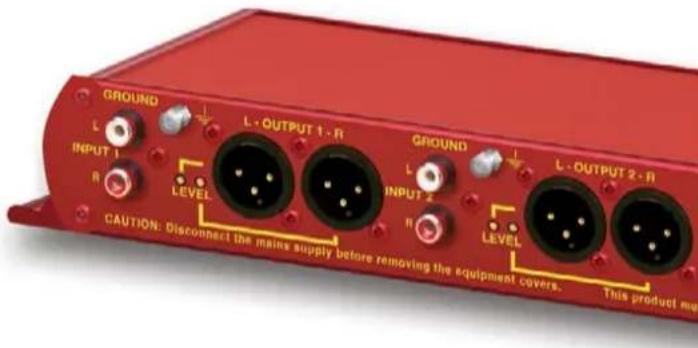
Fitting Redboxes
Redboxes can be fixed to the underside of a desk, or other surfaces using 4.2mm holes in the sides and fixed with 2 x M4 screws or 2 x No. 6 countersink wood screws.


Fig A: RB-RK1 Small Redbox Front Rack-mount Kit.
Safety & Installation
They can also be rack-mounted, with either the front, or rear of the Redbox positioned at the front of the rack (Note: this product is front rack-mounted as standard):
Front Mounting Redboxes: For rack mounting smaller (28cm) units the optional RB-RK1 (Red) or RB-RK1B (Black) kit can be used (which include 4 off M6 panel fixing screws).
Rear Mounting a Redbox: For rear panel mounting you can use either the RB-RK2 (in this case), or RB-RK3, depending on the size of your Redbox.
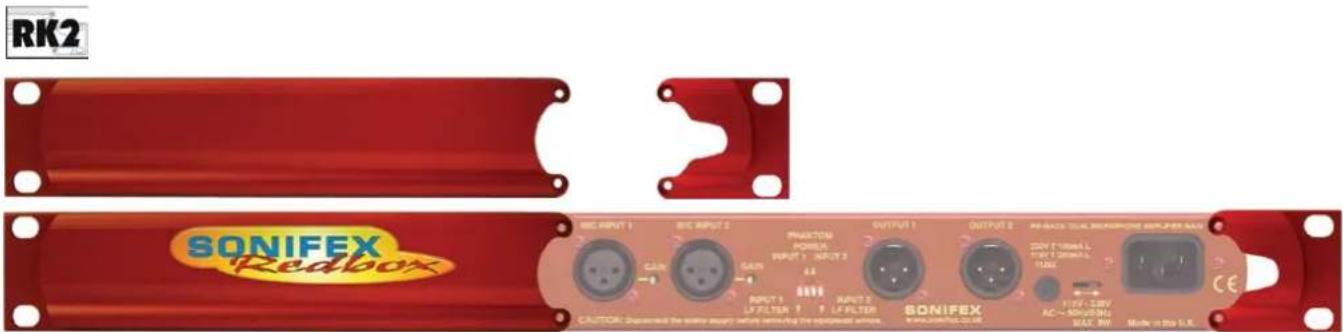
Fig B: RB-RK2 Small Redbox Rear Rack-mount Kit.
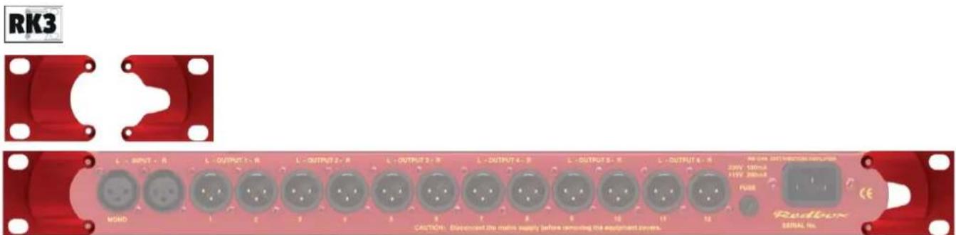
Fig C: RB-RK3 Large Redbox Rear Rack-mount Kit.
1 RB-UL1 Single Stereo Unbalanced to Balanced Converters
Introduction
Fig 1-1: RB-UL1 Front Panel
The RB-UL1 single stereo unit is used for interfacing domestic, or semi-pro unbalanced equipment to professional balanced line levels.
All connections are on the rear panel. The RCA unbalanced inputs have an impedance of 10kΩ bridging and are routed to the balanced XLR-3 outputs with an output impedance of <50Ω.
The RB-UL1 has two inputs & outputs.
The output gain can be individually adjusted for left and right channels by using pre-set potentiometers accessible through the rear panel. A LED power indicator on the front panel displays the power supply connection.
System Block Diagram
Rear Panel Connections and Operation
RCA Phono Inputs (Left and Right)
The stereo left and right RCA inputs are unbalanced and have an impedance of 10kΩ. They are routed to the stereo balanced XLR 3 pin output connectors.
Outputs (Left and Right)
The XLR 3 pin output plug connectors are electronically balanced with an output impedance of <50Ω. They have the following connections:
Pin 1: Screen
Pin 2: Phase
Pin 3: Non-phase
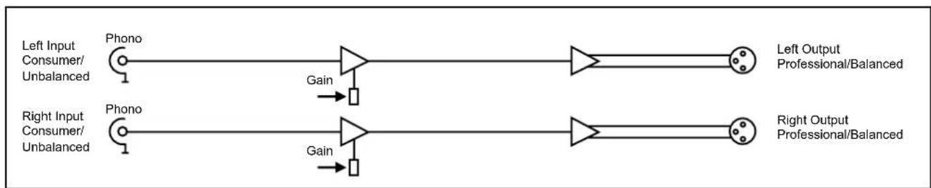
flowchart
graph LR
    A["Left Input Consumer/Unbalanced"] --> B["Phono"]
    C["Right Input Consumer/Unbalanced"] --> D["Phono"]
    B --> E["Gain"]
    D --> F["Gain"]
    E --> G["Left Output Professional/Balanced"]
    F --> H["Right Output Professional/Balanced"]
Fig 1-2: RB-UL1 System Block Diagram
1 Matching Converters - RB-UL1
Output Level Adjustment
The output gain can be individually adjusted for left and right channels through pre-set potentiometers which are accessible through the rear panel. The gain range of the unbalanced to balanced converter is -15dBu to +15dBu ref -15dBu into the unbalanced input.
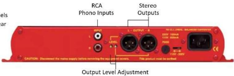
Fig 1-3: RB-UL1 Rear Panel
Technical Specifications RB-UL1
Audio Specifications
| Maximum Input Level: +28dBu |
| Input Impedance: >10kΩ |
| Output Impedance: <50Ω |
| Maximum Output Level: +28dBu |
| Distortion: 0.01% THD @ 1kHz ref +8dB output |
| Noise: -100dB unity gain, ref +8dB output |
| Common Mode Rejection: >66dB typically |
| Frequency Response: 20Hz to 20kHz ±0.1dB (600Ω load, ref 1kHz) |
| Gain Range: | Balanced output: -15dBu to 15dBu, ref -15dBu into unbalanced RCA input |
Connections
| Inputs: | 2 x RCA phono (unbalanced) |
| Outputs: | 2 x XLR 3 pin male (balanced) |
| Mains Input: | Filtered IEC, 110V-120V, or 220-240V |
| switchable, fused, 6W maximum | |
| Fuse Rating: | Anti-surge fuse 100mA 20 x 5mm (230VAC) |
| Anti-surge fuse 250mA 20 x 5mm (115VAC) | |
Equipment Type
| RB-UL1: Single stereo unbalanced to balanced converter | |
| RR1 RR2 | |
Physical Specifications:
| Dimensions (Raw): 28cm (W) x 10.8cm (D) x 4.2cm (H) (1U) |
| 11" (W) x 4.3" (D) x 1.7" (H) (1U) |
| Dimensions (Boxed): 36cm (W) x 20.5cm (D) x 6cm (H) |
| 14.2" (W) x 8" (D) x 2.4" (H) |
| Weight: | Nett: 1.00kg Gross: 1.45kg |
Nett: 2.2lbs Gross: 3.2lbs
2 RB-UL2 Dual Stereo Unbalanced To Balanced Converters
Introduction

Fig 2-1: RB-UL2 Front Panel
The RB-UL2 dual stereo unit is used for interfacing domestic, or semi-pro unbalanced equipment to professional balanced line levels.
All connections are on the rear panel. The RCA unbalanced inputs have an impedance of 10kΩ bridging and are routed to the balanced XLR-3 outputs with an output impedance of <50Ω.
The RB-UL2 has four inputs & outputs.
The output gain can be individually adjusted for left and right channels by using pre-set potentiometers accessible through the rear panel. A LED power indicator on the front panel displays the power supply connection.
System Block Diagram
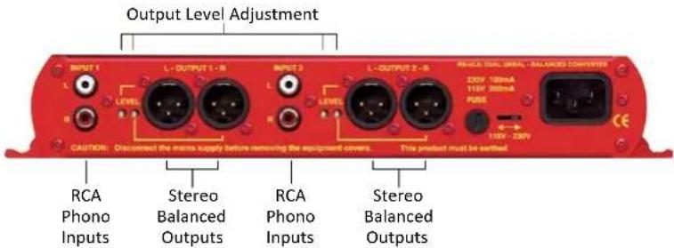
Rear Panel Connections and Operation
RCA Phono Inputs (Left and Right)
The stereo left and right RCA inputs are unbalanced and have an impedance of 10k . They are routed to the stereo balanced XLR 3 pin output connectors.
Outputs (Left and Right)
The XLR 3 pin output plug connectors are electronically balanced with an output impedance of <50Ω. They have the following connections:
Pin 1: Screen
Pin 2: Phase
Pin 3: Non-phase
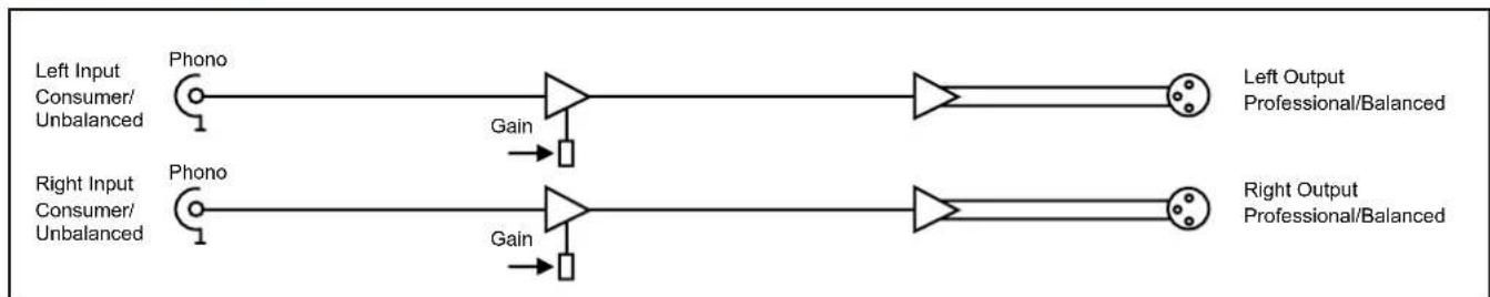
flowchart
graph LR
    A["Left Input Consumer/Unbalanced"] --> B["Phono"]
    C["Right Input Consumer/Unbalanced"] --> D["Phono"]
    B --> E["Gain"]
    D --> F["Gain"]
    E --> G["Left Output Professional/Balanced"]
    F --> H["Right Output Professional/Balanced"]
Fig 2-2: RB-UL2 System Block Diagram
2 Matching Converters - RB-UL2
Output Level Adjustment
The output gain can be individually adjusted for left and right channels through pre-set potentiometers which are accessible through the rear panel. The gain range of the unbalanced to balanced converter is -15dBu to +15dBu ref -15dBu into the unbalanced input.
Technical Specifications RB-UL2
Audio Specifications
| Maximum Input Level: +28dBu |
| Input Impedance: >10kΩ |
| Output Impedance: | <50Ω |
| Maximum Output Level: +28dBu |
| Distortion: 0.01% THD @ 1kHz ref +8dB output |
| Noise: -100dB unity gain, ref +8dB output |
| Common Mode Rejection: |
| >66dB typically |
| Frequency Response: 20Hz to 20kHz ±0.1dB (600Ω load, ref 1kHz) |
| Gain Range: Balanced output: -15dBu to 15dBu, ref -15dBu |
| into unbalanced RCA input |
Fig 2-3: RB-UL2 Rear Panel
Equipment Type
| RB-UL2: | RK1 | RK2 | Dual stereo unbalanced to balanced converter |
Physical Specifications:
| Dimensions (Raw): | 28cm (W) x 10.8cm (D) x 4.2cm (H) (1U) |
| 11" (W) x 4.3" (D) x 1.7" (H) (1U) | |
| Dimensions (Boxed): | 36cm (W) x 20.5cm (D) x 6cm (H) |
| 14.2" (W) x 8" (D) x 2.4" (H) | |
| Weight: | Nett: 1.05kg Gross: 1.5kg |
| Nett: 2.3lbs | Gross: 3.3lbs |
Connections
| Inputs: 4 x RCA phono (unbalanced) |
| Outputs: 4 x XLR 3 pin male (balanced) |
| Mains Input: Filtered IEC, 110V-120V, or 220-240V switchable, fused, 6W maximum |
| Fuse Rating: Anti-surge fuse 100mA 20 x 5mm (230VAC) |
| Anti-surge fuse 250mA 20 x 5mm (115VAC) |
3 RB-UL4 Quad Stereo Unbalanced to Balanced Converters
Introduction

Fig 3-1: RB-UL4 Front Panel
The RB-UL4 quad stereo unit is used for interfacing domestic, or semi-pro unbalanced equipment to professional balanced line levels.
All connections are on the rear panel. The RCA unbalanced inputs have an impedance of 10kΩ bridging and are routed to the balanced XLR-3 outputs with an output impedance of <50Ω.
The RB-UL4 has eight inputs & outputs.
The output gain can be individually adjusted for left and right channels by using pre-set potentiometers accessible through the rear panel. A LED power indicator on the front panel displays the power supply connection.
System Block Diagram
Rear Panel Connections and Operation
RCA Phono Inputs (Left and Right)
The stereo left and right RCA inputs are unbalanced and have an impedance of 10k . They are routed to the stereo balanced XLR 3 pin output connectors.
Outputs (Left and Right)
The XLR 3 pin output plug connectors are electronically balanced with an output impedance of <50Ω. They have the following connections:
Pin 1: Screen
Pin 2: Phase
Pin 3: Non-phase

flowchart
graph LR
    A["Left Input Consumer/Unbalanced"] --> B["Phono"]
    C["Right Input Consumer/Unbalanced"] --> D["Phono"]
    B --> E["Gain"]
    D --> F["Gain"]
    E --> G["Left Output Professional/Balanced"]
    F --> H["Right Output Professional/Balanced"]
Fig 3-2: RB-UL4 System Block Diagram
3 Matching Converters - RB-UL4
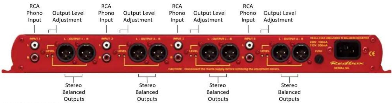
Fig 3-3: RB-UL4 Rear Panel
Output Level Adjustment
The output gain can be individually adjusted for left and right channels through pre-set potentiometers which are accessible through the rear panel. The gain range of the unbalanced to balanced converter is -15dBu to +15dBu ref -15dBu into the unbalanced input.
Technical Specifications RB-UL4
Audio Specifications
Maximum Input Level: +28dBu
Input Impedance: >10kΩ
Output Impedance: <50Ω
Maximum Output Level: +28dBu
Distortion: 0.01% THD @ 1kHz ref +8dB output
Noise: -100dB unity gain, ref +8dB output
Common Mode Rejection:
66dB typically
Frequency Response: 20Hz to 20kHz ±0.1dB (600Ω load, ref 1kHz)
Gain Range: Balanced output: -15dBu to 15dBu, ref -15dBu into unbalanced RCA input
Connections
Inputs: 8 x RCA phono (unbalanced)
Outputs: 8 x XLR 3 pin male (balanced)
Mains Input: Filtered IEC, 110V-120V, or 220-240V switchable, fused, 6W maximum
Fuse Rating: Anti-surge fuse 100mA 20 x 5mm (230VAC) Anti-surge fuse 250mA 20 x 5mm (115VAC)
Equipment Type
RB-UL4: RK3 Quad stereo unbalanced to balanced converter
Physical Specifications:
Dimensions (Raw): 48cm (W) x 10.8cm (D) x 4.2cm (H) (1U) 19" (W) x 4.3" (D) x 1.7" (H) (1U)
Dimensions (Boxed): 53cm (W) x 20.5cm (D) x 6cm (H) 21" (W) x 8" (D) x 2.4" (H)
Weight: Nett: 1.3kg Gross: 1.9kg Nett: 2.9lbs Gross: 4.2lbs
4 RB-LU4 Quad Stereo Balanced to Unbalanced Converter
Introduction

Fig 4-1: RB-LU4 Front Panel
The RB-LU4 is a quad stereo unit for interfacing professional balanced equipment to domestic, or semi-pro unbalanced line levels.
All connections are on the rear panel. The eight XLR-3 electronically balanced inputs have an impedance of 20kΩ bridging and are routed to eight unbalanced RCA phono outputs with an output impedance of <50Ω.
The output gain can be individually adjusted for left and right channels by using pre-set potentiometers accessible through the rear panel. An LED power indicator is situated on the front panel, which displays the power supply connection.
4 Matching Converters - RB-LU4
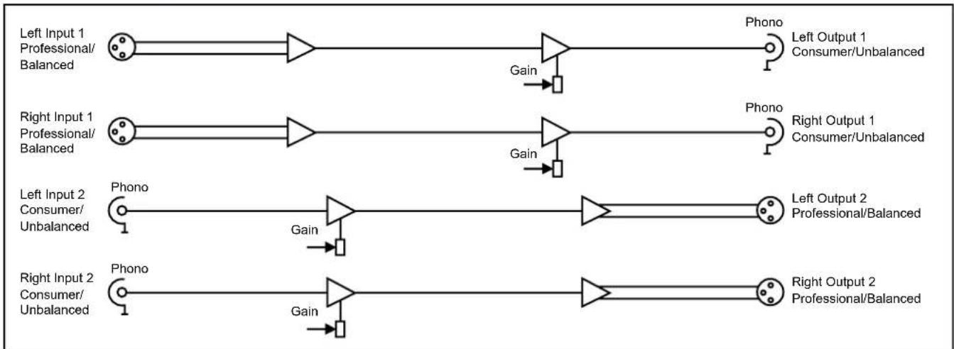
System Block Diagram
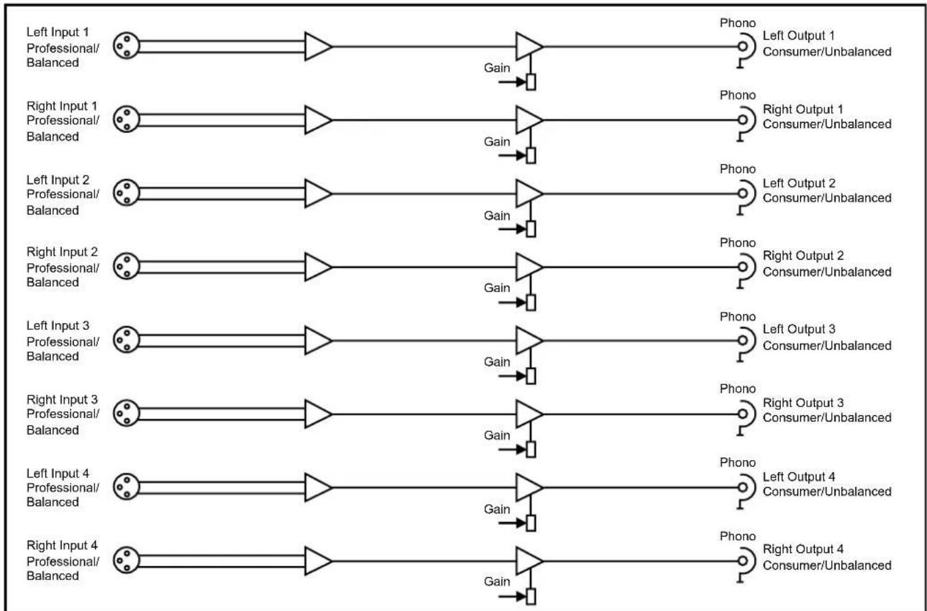
flowchart
graph LR
    A["Left Input 1 Professional/Balanced"] --> B["Phono Left Output 1 Consumer/Unbalanced"]
    C["Right Input 1 Professional/Balanced"] --> D["Phono Right Output 1 Consumer/Unbalanced"]
    E["Left Input 2 Professional/Balanced"] --> F["Phono Left Output 2 Consumer/Unbalanced"]
    G["Right Input 2 Professional/Balanced"] --> H["Phono Right Output 2 Consumer/Unbalanced"]
    I["Left Input 3 Professional/Balanced"] --> J["Phono Left Output 3 Consumer/Unbalanced"]
    K["Right Input 3 Professional/Balanced"] --> L["Phono Right Output 3 Consumer/Unbalanced"]
    M["Left Input 4 Professional/Balanced"] --> N["Phono Left Output 4 Consumer/Unbalanced"]
    O["Right Input 4 Professional/Balanced"] --> P["Phono Right Output 4 Consumer/Unbalanced"]
    B --> Q["Gain"]
    D --> R["Gain"]
    F --> S["Gain"]
    H --> T["Gain"]
    J --> U["Gain"]
    L --> V["Gain"]
    N --> W["Gain"]
    P --> X["Gain"]
Fig 4-2: RB-LU4 System Block Diagram
Rear Panel Connections and Operation
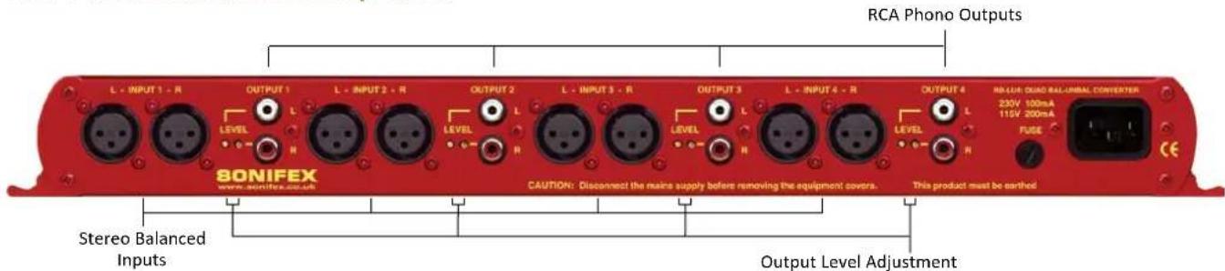
Fig 4-3: RB-LU4 Rear Panel
Inputs 1-4 (Left and Right)
The XLR 3 pin sockets used for the left and right channel inputs of Input 1 are electronically balanced and have an impedance of 20kΩ bridging. They are routed to an unbalanced RCA (phono) output with an output impedance of <50Ω. Each XLR has the following connections:
Pin 1: Screen
Pin 2: Phase
Pin 3: Non-phase
RCA Phono Outputs 1-4 (Left and Right)
These RCA (phono) outputs are unbalanced and have an output impedance of <50 .
Output Level Adjustment
The output gain can be individually adjusted for left and right channels through pre-set potentiometers which are accessible through the rear panel. The gain of the balanced to unbalanced converter is variable within a range of -28dBu to +15dBu ref. -15dBu into the balanced input.
Technical Specifications RB-LU4
Audio Specifications
Maximum Input Level: +28dBu
Input Impedance (XLR): >20kΩ balanced bridging
Output Impedance (RCA) : <50Ω
Maximum Output Level: +22dBu
Distortion: 0.01% THD @ 1kHz, ref +8dBu output
Noise: -100dB, unity gain, ref +8dBu output
Common Mode Rejection: >66dB typically
Frequency Response: 20Hz to 20kHz ±0.1dB (600Ω load, ref 1kHz)
Gain Range: Unbalanced Output: -28dBu to +15dBu, ref -15dBu into balanced XLR input
Connections
Inputs: 8 x XLR 3 pin female (Balanced)
Outputs: 8 x RCA phono (Unbalanced)
Mains Input: Filtered IEC, 110V-120V, or 220-240V switchable, fused, 6W maximum
4 Matching Converters - RB-LU4
Fuse Rating: Anti-surge fuse 100mA 20 x 5mm (230VAC) Anti-surge fuse 250mA 20 x 5mm (115VAC)
Equipment Type
RB-LU4: Quad storage balanced to unbalanced converter
Physical Specifications
Dimensions (Raw): 48cm (W) x 10.8cm (D) x 4.2cm (H) (1U) 19" (W) x 4.3" (D) x 1.7" (H) (1U)
Dimensions (Boxed): 53cm (W) x 20.5cm (D) x 6cm (H) 21" (W) x 8" (D) x 2.4" (H)
Weight: Nett: 1.3kg Gross: 1.9kg Nett: 2.9lbs Gross: 4.2lbs
5 RB-BL2 Single Bi-Directional Matching Converter
Introduction

Fig 5-1: RB-BL2 Front Panel
The RB-BL2 is a bi-directional stereo unit for interfacing domestic, or semi-pro unbalanced equipment to professional balanced line levels, and vice-versa.
All connections are on the rear panel. The XLR-3 electronically balanced inputs have an impedance of 20kΩ bridging and are routed to unbalanced RCA (phono) outputs with an output impedance of <50Ω.
The RCA unbalanced inputs have an impedance of 10kΩ bridging and are routed to balanced XLR-3 outputs with an output impedance of <50Ω.
The output gain can be individually adjusted for left and right channels by using pre-set potentiometers accessible through the rear panel. An LED power indicator on the front panel displays the power supply connection.
System Block Diagram
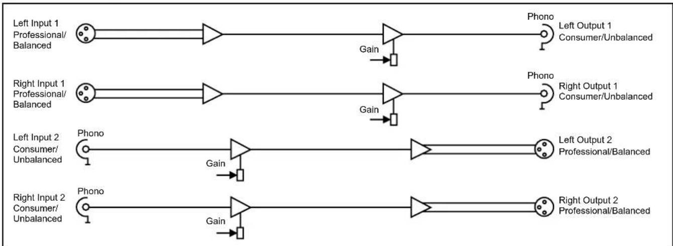
flowchart
graph LR
    A["Left Input 1 Professional/Balanced"] --> B["Phono"]
    C["Right Input 1 Professional/Balanced"] --> D["Phono"]
    E["Left Input 2 Consumer/Unbalanced"] --> F["Phono"]
    G["Right Input 2 Consumer/Unbalanced"] --> H["Phono"]
    B --> I["Gain"]
    D --> J["Gain"]
    F --> K["Gain"]
    H --> L["Gain"]
    I --> M["Left Output 1 Consumer/Unbalanced"]
    J --> N["Right Output 1 Consumer/Unbalanced"]
    K --> O["Left Output 2 Professional/Balanced"]
    L --> P["Right Output 2 Professional/Balanced"]
Fig 5-2: RB-BL2 System Block Diagram
5 Matching Converters - RB-BL2
Rear Panel Connections and Operation
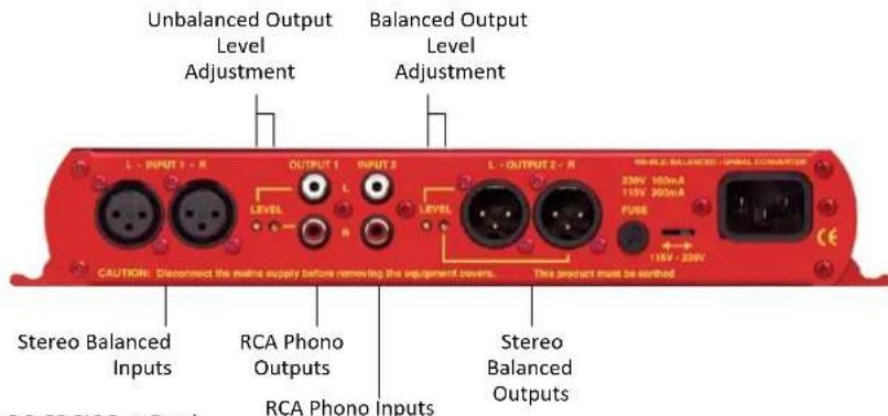
Fig 5-3: RB-BL2 Rear Panel
Balanced to Unbalanced Connections
Inputs 1 (Left & Right)
The XLR 3 pin sockets used for the left and right channel signals of Input 1 are electronically balanced and have an impedance of 20kΩ bridging. They are routed to unbalanced RCA (phono) outputs with an output impedance of <50Ω. Each XLR has the following connections:
Pin 1: Screen.
Pin 2: Phase.
Pin 3: Non-phase.
RCA Phono Outputs 1 (Left & Right)
These RCA (phono) outputs are unbalanced and have an output impedance of <50 .
Output Level Adjustment
The output gain can be individually adjusted for left and right channels through pre-set potentiometers which are accessible through the rear panel. The gain of the balanced to unbalanced converter is variable within a range of 0dBu to -28dBu ref -0dBu into the balanced input.
Unbalanced to Balanced Connections
RCA Phono Inputs 2 (Left & Right)
The left and right RCA inputs 2 are unbalanced and have an impedance of 10kΩ.
They are routed to the balanced XLR 3 pin outputs 2.
Outputs 2 (Left & Right)
The XLR 3 pin output plug connectors are electronically balanced with an output impedance of <50Ω. They have the following connections:
Pin 1: Screen.
Pin 2: Phase.
Pin 3: Non-phase.
Technical Specifications RB-BL2
Audio Specifications
Maximum Input Level: +28dBu
Maximum Output Level: +28dBu
Input Impedance (RCA) : >10kΩ unbalanced
Input Impedance (XLR): >20kΩ balanced bridging
Output Impedance (RCA) : <50Ω
Output Impedance (XLR): <50Ω
Distortion: 0.01% THD @ 1kHz, ref +8dBu output
Noise: -100dB, unity gain, ref +8dBu output
Common Mode Rejection:> 66dB typically
Frequency Response: 20Hz to 20kHz ±0.1dB (600Ω load, ref 1kHz)
Gain Range: Unbalanced Output: -28dBu to +15dBu, ref -15dBu into balanced XLR input
Gain Range: Balanced Output: -15dBu to +15dBu, ref -15dBu into unbalanced RCA input
Connections
Inputs: 2 x XLR 3 pin female
(balanced),
2 x RCA phono (unbalanced)
Outputs: 2 x XLR 3 pin male (balanced),
2 x RCA phono (unbalanced)
Mains Input:
Filtered IEC, 110V-120V, or 220-240V
switchable, fused, 6W maximum
Fuse Rating:
Anti-surge fuse 100mA 20 x 5mm (230VAC)
Anti-surge fuse 250mA 20 x 5mm (115VAC)
Equipment Type
RB-BL2:


Single stereo bi-directional matching converter
Physical Specification
Dimensions (Raw):
28cm (W) × 10.8cm (D) × 4.2cm (H) (1U)
6 RB-BL4 Dual Stereo Bi-Directional Matching Converter
Introduction

Fig 6-1: RB-BL4 Front Panel
The RB-BL4 is a dual bi-directional stereo unit for interfacing domestic, or semi-pro unbalanced equipment to professional balanced line levels, and vice-versa.
All connections are on the rear panel. The XLR-3 electronically balanced inputs have an impedance of 20kΩ bridging and are routed to unbalanced RCA (phono) outputs with an output impedance of <50Ω.
System Block Diagram
flowchart
graph LR
    A["Left Input 1 Professional/Balanced"] --> B["Phono"]
    C["Right Input 1 Professional/Balanced"] --> D["Phono"]
    E["Left Input 2 Consumer/Unbalanced"] --> F["Phono"]
    G["Right Input 2 Consumer/Unbalanced"] --> H["Phono"]
    B --> I["Gain"]
    D --> J["Gain"]
    F --> K["Gain"]
    H --> L["Gain"]
    I --> M["Phono"]
    J --> N["Phono"]
    K --> O["Phono"]
    L --> P["Phono"]
    M --> Q["Left Output 1 Consumer/Unbalanced"]
    N --> R["Left Output 2 Professional/Balanced"]
    O --> S["Right Output 1 Consumer/Unbalanced"]
    P --> T["Right Output 2 Professional/Balanced"]
Fig 6-2: RB-BL4 System Block Diagram. (Note the RB-BL4 contains 2 of these circuits)
Rear Panel Connections and Operation
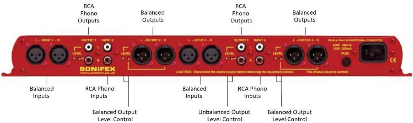
Fig 6-3: RB-BL4 Rear Panel
Balanced to Unbalanced Connections
Inputs 1 & 3 (Left & Right)
The XLR 3 pin sockets used for the left and right channel signals of Inputs 1 & 3 are electronically balanced and have an impedance of 20k bridging. They are routed to unbalanced RCA (phono) outputs with an output impedance of <50 . Each XLR has the following connections:
Pin 1: Screen.
Pin 2: Phase.
Pin 3: Non-phase.
RCA Phono Outputs 1 & 3 (Left & Right)
These RCA (phono) outputs are unbalanced and have an output impedance of <50 .
Output Level Adjustment
The output gain can be individually adjusted for left and right channels through pre-set potentiometers which are accessible through the rear panel. The gain of the balanced to unbalanced converter is variable within a range of 0dBu to -28dBu ref -0dBu into the balanced input.
6 Matching Converters - RB-BL4
Unbalanced to Balanced Connections
RCA Phono Inputs 2 & 4 (Left & Right)
The left and right RCA inputs 2 & 4 are unbalanced and have an impedance of 10kΩ. They are routed to the balanced XLR 3 pin outputs 2 & 4.
Outputs 2 & 4 (Left & Right)
The XLR 3 pin output plug connectors are electronically balanced with an output impedance of <50 . They have the following connections:
Pin 1: Screen.
Pin 2: Phase.
Pin 3: Non-phase.
Technical Specifications RB-BL4
Audio Specifications
| Maximum Input Level: +28dBu |
| Maximum Output Level: +28dBu |
| Input Impedance (RCA) : >10kΩ unbalanced |
| Input Impedance (XLR) : >20kΩ balanced bridging |
| Output Impedance (RCA) : <50Ω |
| Output Impedance (XLR) : <50Ω |
| Distortion: 0.01% THD @ 1kHz, ref +8dBu output |
| Noise: -100dB, unity gain, ref +8dBu output |
| Common Mode Rejection: >66dB typically |
| Frequency Response: 20Hz to 20kHz ±0.1dB (600Ω load, ref 1kHz) |
| Gain Range: Unbalanced Output: -28dBu to +15dBu, ref -15dBu into balanced XLR input |
| Gain Range: Balanced Output: -15dBu to +15dBu, ref -15dBu into unbalanced RCA input |
Connections
| Inputs: 4 x XLR 3 pin female (balanced),4 x RCA phono (unbalanced) |
| Outputs: 4 x XLR 3 pin male (balanced),4 x RCA phono (unbalanced) |
| Mains Input: Filtered IEC, 110V-120V, or 220-240Vswitchable, fused, 6W maximum |
| Fuse Rating: Anti-surge fuse 100mA 20 x 5mm (230VAC)Anti-surge fuse 250mA 20 x 5mm (115VAC) |
Equipment Type
| RB-BL4: | PK3 | Dual stereo bi-directional matching converter |
Physical Specification
| Dimensions (Raw) | 48cm (W) x 10.8cm (D) x 4.2cm (H) (1U) |
| 19" (W) x 4.3" (D) x 1.7" (H) (1U) | |
| Dimensions (Boxed) | 53cm (W) x 20.5cm (D) x 6cm (H) |
| 21" (W) x 8" (D) x 2.4" (H) | |
| Weight | Nett: 1.3kg Gross: 1.9kg |
| Nett: 2.9lbs Gross: 4.2lbs | |
The RCA unbalanced inputs have an impedance of 10kΩ bridging and are routed to balanced XLR-3 outputs with an output impedance of <50Ω.
The output gain can be individually adjusted for left and right channels by using pre-set potentiometers accessible through the rear panel. An LED power indicator on the front panel displays the power supply connection.
7 RB-PA2 Dual Stereo RIAA Phono Amplifier
Introduction

Fig 7-1: RB-PA2 Front Panel
The RB-PA2 is a dual stereo RIAA equalised phono amplifier. This record player preamp amplifies the small signal from your pick up cartridge (either moving magnet or high output moving coil magnetic) and provides the necessary RIAA equalisation required for vinyl records, to match it to a line input of your mixer, or amplifier. It uses a clean RIAA response making it ideal for use with broadcast turntables and DJ decks and where vinyl records are being archived to CD for high quality transfers, or for converting albums to mp3.
It operates with phono cartridges with a nominal output of 1mV to 25mV and has been specifically tested to work with the Technics SL-1200 ^™ and 1210 ^™ range of turntables. Quality high specification components have
been used together with low noise, fast acting operational amplifiers to produce a superbly transparent signal path. Additionally, the RB-PA2 runs without a rumble filter to produce a powerful bass response.
The RB-PA2 is a dual stereo unit to interface up to two turntables. The inputs are phono connectors with Neutrik XLR connectors for the balanced outputs, which may be wired unbalanced if required. Output gain is individually adjustable for left and right channels in the range 35dB to 65dB by using pre-set potentiometers. Frequency response is held within 0.5dB of the RIAA curve and noise is typically better than -84dB RMS A weighted at 40dB gain.
System Block Diagram
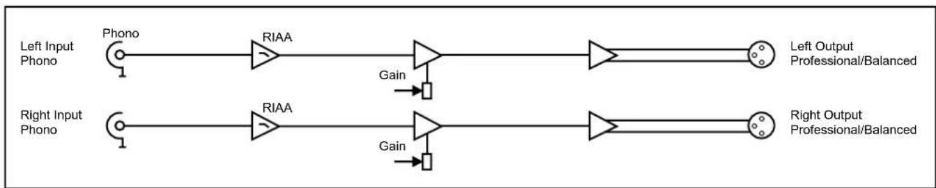
flowchart
graph LR
    A["Left Input Phono"] --> B["Phono"]
    B --> C["RIAA"]
    C --> D["Gain"]
    D --> E["Right Input Phono"]
    E --> F["RIAA"]
    F --> G["Gain"]
    G --> H["Right Output Professional/Balanced"]
    style A fill:#f9f,stroke:#333
    style E fill:#f9f,stroke:#333
Fig 7-2: RB-PA2 System Block Diagram For a Single Stereo Channel
7 Matching Converters - RB-PA2
Rear Panel Connections and Operation
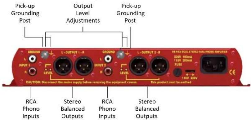
Fig 7-3: RB-PA2 Rear Panel
RCA Phono Inputs (Left and Right)
The stereo left and right RCA inputs are unbalanced and have an impedance of 47kΩ. They are routed to the stereo balanced XLR 3 pin output connectors.
Outputs (Left and Right)
The XLR 3 pin output plug connectors are electronically balanced with an output impedance of <50Ω. They have the following connections:
Pin 1: Screen
Pin 2: Phase
Pin 3: Non-phase
Output Level Adjustment
The output gain can be individually adjusted for left and right channels through pre-set potentiometers which are accessible through the rear panel. The gain range of each channel is adjustable between 30dB gain and 58dB gain.
Pick-up Grounding Post
This acts as an earth ground connection to connect to a turntable pick-up ground point.
Technical Specifications RB-PA2
Audio Specifications
Maximum Input Level: +28dBu
Input Impedance: >47kΩ
Input Sensitivity Range: 1mV to 25mV (ref 1kHz)
Maximum Output Level: +28dBu
Output Impedance: <50Ω
Output Gain Range: Adjustable 38dB to 58dB gain via 4 multi-turn pots
Crosstalk: Better than -80dBu at 1kHz
Frequency Response: 10Hz-150kHz (-3dB)
RIAA Accuracy: Within 0.5dB of RIAA curve
Distortion: 0.01% THD @ 1kHz, ref +8dBu output
Noise: -77dB (CCIR Q-Pk, 20Hz-20kHz)
Headroom: 27dB for 3mV input
Dynamic Range: 90dB
Connections
Inputs: 4 x RCA phono (unbalanced)
Outputs: 4 x XLR 3 pin male (balanced)
Earth Tag: Grounding turret tag
Mains Input: Filtered IEC, 110V-120V, or 220-240V switchable, fused 6W maximum
Fuse Rating: Anti-surge fuse 100mA 20 x 5mm (230VAC) Anti-surge fuse 250mA 20 x 5mm (115VAC)
Equipment Type
RB-PA2:

Dual stereo phono amplifier and RIAA gram amplifier
Physical Specifications
Dimensions (Raw): 28cm (W) x 10.8cm (D) x 4.2cm (H) (1U) 11" (W) x 4.3" (D) x 1.7" (H) (1U)
Dimensions (Boxed): 36cm (W) x 20.5cm (D) x 6cm (H) 14.2" (W) x 8" (D) x 2.4" (H)
Weight:
Nett: 1.1kg Gross: 1.5kg Nett: 2.4lbs Gross: 3.3lbs
8 Matching Converters - RB-LI2
8 RB-LI2 Stereo Line Isolation Unit
Introduction

Fig 8-1: RB-LI2 Front Panel.
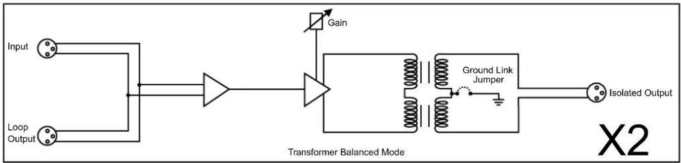
The RB-LI2 stereo line isolation unit is used to isolate audio signals from inter area ground hum loops, which could be caused by equipment being powered by different mains power supplies, or different phases on the same supply. The input and output are connected together through a transformer, which has internal jumpers allowing the outputs to be balanced about ground.
There is also a loop-through output, so that the RB-LI2 can be inserted into a line, forming a transformer balanced distribution point.
This unit is useful where audio is required to be driven over a relatively long length of cable. By isolating the signal using transformers, ground loop currents that can be present in non-isolated signals, are eradicated completely.
System Block Diagram
flowchart
graph LR
    A["Input"] --> B["Transformer Balanced Mode"]
    C["Loop Output"] --> B
    B --> D["Gain"]
    D --> E["Ground Link Jumper"]
    E --> F["Isolated Output"]
    style B fill:#f9f,stroke:#333
    style E fill:#ccf,stroke:#333
Fig 8-2: RB-LI2 System Block Diagram
Rear Panel Connections and Operation
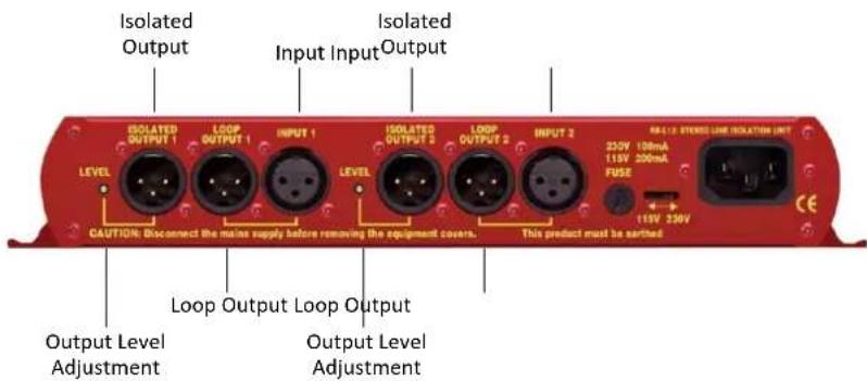
Fig 8-3: RB-LI2 Rear Panel
Inputs
There are 2 input XLR 3 pin sockets. They have the following connections:
Pin 1: Screen
Pin 2: Phase
Pin 3: Non-phase
Isolated Outputs
Each of the 2 inputs has a corresponding isolated output, an XLR 3 pin plug with the following connections:
Pin 1: Screen
Pin 2: Phase
Pin 3: Non-phase
Loop Outputs
Each of the 2 inputs has a corresponding loop-through output, an XLR 3 pin plug with the following connections:
Pin 1: Screen
Pin 2: Phase
Pin 3: Non-phase
Output Level Adjustment
The isolated outputs can be individually adjusted using pre-set potentiometers, which are accessible through the rear panel. The gain range of the stereo line isolation unit is -15dB to +13.5dB (28.5dB).
Internal Jumpers
The unit has jumpers that are used to balance the output about ground. By default these are not fitted when the unit leaves the factory.
To get inside the RB-LI2, first ensure that it has been disconnected from the mains power and that the mains IEC lead to the unit has been removed. Observing anti-static precautions, undo the four-crosshead screws on the back panel at the far left and far right of the panel (2 at each end). Also undo the small brass screws, which hold the top and bottom panels to the rear panel. The rear panel should slide backwards out of the unit together with the main circuit board.
8 Matching Converters - RB-LI2
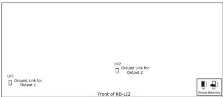
Fig 8-4: RB-LI2 Jumper Positions on the PCB
Technical Specifications RB-LI2
Audio Specification
Output Impedance: <150Ω
Frequency Response: 10Hz to 36kHz ±0.5dB
Common Mode Rejection:<64dB
Distortion: 0.5% THD @ 40Hz, ref +17dBu output
Noise: -100dB unity gain ref +8dB
Gain Range: -15dB to +13.5dB (28.5dB)
Connections
Inputs: 2 x XLR 3 pin female
Isolated Outputs: 2 x XLR 3 pin male
Loop Outputs: 2 x XLR 3 pin male
Fuse Rating: Anti-surge fuse 100mA 20 x 5mm (230VAC)
Anti-surge fuse 250mA 20 x 5mm (115VAC)
Equipment Type
RB-LI2: Stereoline isolation unit
Physical Specifications
Dimensions (Raw): 28cm (W) x 10.8cm (D) x 4.2cm (H) (1U) 11" (W) x 4.3" (D) x 1.7" (H) (1U)
Dimensions (Boxed): 36cm (W) x 20.5cm (D) x 6cm (H) 14.2" (W) x 8" (D) x 2.4" (H)
Weight: Nett: 1.1kg Gross: 1.5kg
Nett: 2.4lbs Gross: 3.3lbs
9 RB-PLI6 6 Way Mono Passive Line Isolation Unit
Introduction

Fig 9-1: RB-PLI6 Front Panel
The RB-PLI6 6 way mono passive line isolation unit is used to isolate audio signals from inter area ground hum loops, which could be caused by equipment being powered by different mains power supplies or phases on the same supply.
The input and output are connected together through a transformer and the unit has internal jumpers allowing the inputs and/or outputs to be balanced about ground. The unit requires no mains power for operation.
This unit is useful where audio is required to be driven over a relatively long length of cable. By isolating the signal using transformers, ground loop currents that can be present in non-isolated signals, are eradicated completely.
System Block Diagram
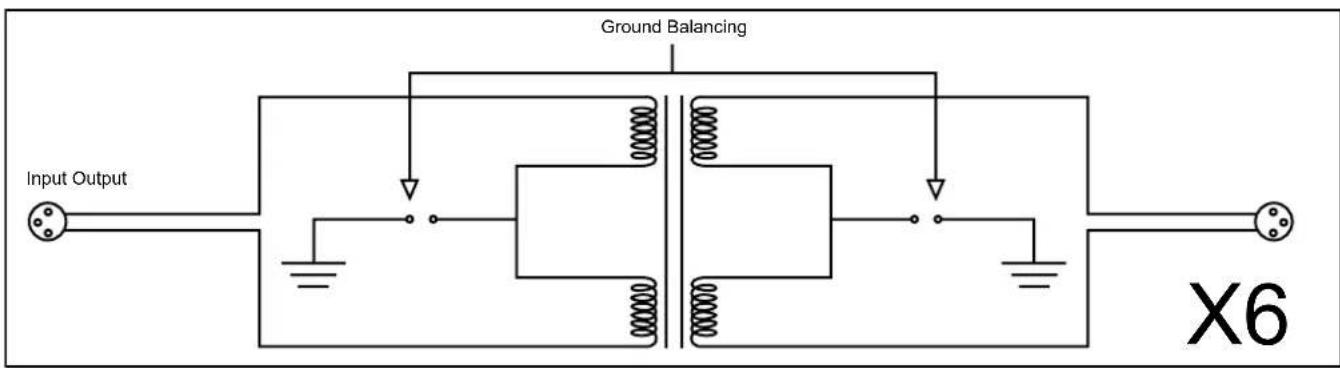
Fig 9-2: RB-PLI6 System Block Diagram
9 Matching Converters - RB-PLI6
Rear Panel Connections and Operation
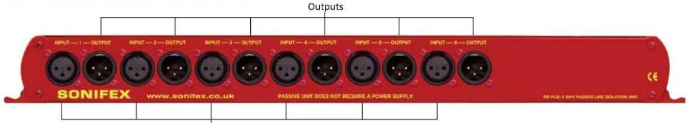
Fig 9-3: RB-PLI6 Rear Panel
Inputs
Inputs
There are 6 off XLR 3 pin socket inputs. They have the following
connections:
Pin 1: Screen
Pin 2: Phase
Pin 3: Non-phase
Outputs
There are 6 off XLR 3 pin plug outputs. They have the following connections:
Pin 1: Screen
Pin 2: Phase
Pin 3: Non-phase
Ground-link Internal Jumpers
The unit has jumpers that are used to balance either the input, or the output, about ground. By default these are not fitted when the unit leaves the factory.
To get inside the RB-PLI6, observing anti-static precautions, undo the four crosshead screws on the back panel at the far left and far right of the panel (2 at each end). Also undo the small brass screws, which hold the top and bottom panels to the rear panel. The rear panel should slide backwards out of the unit together with the main circuit board.
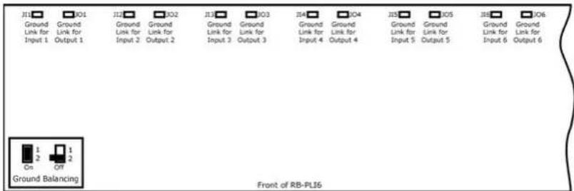
Fig 9-4: RB-PL16 Ground-link Jumper Settings
Technical Specifications RB-PLI6
Audio Specification
Output Impedance: <150Ω
Distortion: 0.5% THD @ 40Hz, ref +17dBu output
Common Mode Rejection:<64dB typically
Frequency Response: 10Hz to 36kHz ±0.5dB
Connections
Inputs: 6 x XLR 3 pin female (balanced)
Outputs: 6 x XLR 3 pin male (balanced)
Equipment Type
RB-PLI6: 6-wa mono passive line isolation unit
Physical Specifications
Dimensions (Raw): 48cm (W) x 10.8cm (D) x 4.2cm (H) (1U) 19" (W) x 4.3" (D) x 1.7" (H) (1U)
Dimensions (Boxed): 53cm (W) x 20.5cm (D) x 6cm (H) 21" (W) x 8" (D) x 2.4" (H)
Weight: Nett: 1.5kg Gross: 1.9kg Nett: 3.3lbs Gross: 4.2lbs
SONIFEX
www.sonifex.co.uk
t:+44 (0)1933 650 700
f:+44 (0)1933 650 726
sales@sonifex.co.uk
- Redbox Handbook 3
- Contents
- Figures
- SONIFEX
- Register Online for an Extended 2 Year Warranty
- Warranty
- Product Warranty - 2 Year Extended
- Sonifex Warranty & Liability Terms & Conditions
- Definitions
- Warranty
- Unpacking Your Product
- CE Conformity
- Item
- Quantity
- Repairs & Returns
- Safety & Installation of Mains Operated Equipment
- Voltage Setting Checks
- Fuse Rating
- Power Cable & Connection
- WEEE Directive
- Atmosphere/Environment
- Fitting Redboxes
- Safety & Installation
- RB-UL1 Single Stereo Unbalanced to Balanced Converters
- Introduction
- System Block Diagram
- Rear Panel Connections and Operation
- RCA Phono Inputs (Left and Right)
- Outputs (Left and Right)
- Matching Converters - RB-UL1
- Output Level Adjustment
- Technical Specifications RB-UL1
- RB-UL2 Dual Stereo Unbalanced To Balanced Converters
- Matching Converters - RB-UL2
- Technical Specifications RB-UL2
- RB-UL4 Quad Stereo Unbalanced to Balanced Converters
- Technical Specifications RB-UL4
- Audio Specifications
- Connections
- Equipment Type
- Physical Specifications:
- RB-LU4 Quad Stereo Balanced to Unbalanced Converter
- Matching Converters - RB-LU4
- Inputs 1-4 (Left and Right)
- RCA Phono Outputs 1-4 (Left and Right)
- Technical Specifications RB-LU4
- Physical Specifications
- RB-BL2 Single Bi-Directional Matching Converter
- Matching Converters - RB-BL2
- Balanced to Unbalanced Connections
- Inputs 1 (Left & Right)
- RCA Phono Outputs 1 (Left & Right)
- Unbalanced to Balanced Connections
- RCA Phono Inputs 2 (Left & Right)
- Outputs 2 (Left & Right)
- Technical Specifications RB-BL2
- Physical Specification
- RB-BL4 Dual Stereo Bi-Directional Matching Converter
- Inputs 1 & 3 (Left & Right)
- RCA Phono Outputs 1 & 3 (Left & Right)
- Matching Converters - RB-BL4
- RCA Phono Inputs 2 & 4 (Left & Right)
- Outputs 2 & 4 (Left & Right)
- Technical Specifications RB-BL4
- RB-PA2 Dual Stereo RIAA Phono Amplifier
- Matching Converters - RB-PA2
- Pick-up Grounding Post
- Technical Specifications RB-PA2
- Matching Converters - RB-LI2
- RB-LI2 Stereo Line Isolation Unit
- Inputs
- Isolated Outputs
- Loop Outputs
- Internal Jumpers
- Technical Specifications RB-LI2
- Audio Specification
- RB-PLI6 6 Way Mono Passive Line Isolation Unit
- Matching Converters - RB-PLI6
- Outputs
- Ground-link Internal Jumpers
- Technical Specifications RB-PLI6
Brand : Sonifex
Model : Redbox RB-PLI6
Category : Uncategorized