
Voyage - Speaker Martin Logan - Free user manual and instructions
Find the device manual for free Voyage Martin Logan in PDF.


| Product Type | Electrostatic Loudspeaker |
| Dimensions (H x W x D) | 47 x 11 x 19 inches |
| Weight | 55 lbs |
| Power Handling | 200 W |
| Frequency Response | 35 Hz - 22 kHz |
| Impedance | 4 ohms |
| Sensitivity | 90 dB |
| Finish Options | Black, Cherry |
| Main Functions | High-resolution audio reproduction, wide soundstage |
| Cleaning and Care | Use a soft dry cloth; avoid liquids and abrasive cleaners |
| Safety Precautions | Keep away from moisture; do not block ventilation; stable placement |
| Spare Parts and Repairability | Contact authorized service center for parts and repairs |
| General Information | Patented electrostatic panel technology; built-in powered woofers |
Frequently Asked Questions - Voyage Martin Logan
User questions about Voyage Martin Logan
0 question about this device. Answer the ones you know or ask your own.
Ask a new question about this device
Download the instructions for your Speaker in PDF format for free! Find your manual Voyage - Martin Logan and take your electronic device back in hand. On this page are published all the documents necessary for the use of your device. Voyage by Martin Logan.
USER MANUAL Voyage Martin Logan
natural_image
Exterior view of a modern office building (no signage)Contents Introduction
Contents and Introduction ....2
Contents
Introduction
Installation ....3
Placement
Horizontal Installation
Installing the Voyage
Installing an IR Repeater .....9
Removing the End Caps for Painting .....10
ATF (Advanced Thin Film) .....11
Frequently Asked Questions and Troubleshooting 12
General Information ....13
Specifications
Warranty and Registration
Service
Glossary of Audio Terms .....14
Congratulations! You have invested in a new world of high performance audio!
The MartinLogan Voyage represents the culmination of an intensive, dedicated group research program directed toward establishing a world class reference monitor utilizing leading-edge technology, without compromising durability, reliability, craftsmanship or aesthetic design.
The materials in your new Voyage speaker are of the highest quality and will provide years of enduring enjoyment and deepening respect.
This User's Manual will explain in detail the operation of your Voyage speaker and the philosophy applied to their design. A clear understanding of your speaker will insure that you obtain maximum performance and pleasure from this most exacting transducer. It has been designed and constructed to give you years of trouble-free listening enjoyment.

The lightning bolt flash with arrowhead symbol within an equilateral triangle is intended to alert the user to the presence of uninsulated "dangerous voltage" within the product's enclosure that may be of sufficient magnitude to constitute a risk of electric shock.

The exclamation point within an equilateral triangle is intended to alert the user to the presence of important operating and maintenance (servicing) instructions in the literature accompanying the appliance.

The fire within an equilateral triangle is intended to alert the user to the potential of creating a fire hazard if they do not follow the instructions.

The dollar sign within an equilateral triangle is intended to alert the user that they run the risk of causing damage that could be potentially expensive to repair if they don't follow the instructions.

WARNING!
• Refer servicing to a qualified technician.
- To prevent fire or shock hazard, do not expose this module to moisture.
- Turn amplifier off should any abnormal conditions occur.
- Do not drive speaker beyond its rated power.
Placement
To achieve maximum performance, it is recommended that the Voyage not be installed near a room corner or directly behind furniture. When used as a front left/right channel, it is recommended that the listening position be no closer to the wall then the distance between the speakers.
Horizontal Installation
Although most users will mount the Voyage in a vertical orientation, it can also be mounted in a horizontal orientation (for use as a center channel). If you plan to use the Voyage in a horizontal orientation, it will cross drywall studs and the wall will require modification. A bonded contractor should be contacted to mount the Voyage in a horizontal orientation.
Installing the Voyage
NOTE: These instructions must be carefully followed to assure that your Voyage is safely installed. Study them thoroughly before installing your Voyage's.
NOTE: The following instructions assume the mounting surface is of standard wood frame and standard sheet rock construction. If you wish to mount the Voyage to another type of material, you should consult a bonded contractor.

Warning! Before installing check for obstructions behind the drywall (electrical, plumbing and other fixtures). To do this make a small hole, cutting at a 45° angle (this will make the hole easier to patch if obstructions are found). Only cut the mounting hole after you have verified there are no obstructions behind the wall.


hole, cutting at a 45° angle (this will make the hole easier to patch if obstructions are found). Only cut the mounting hole after you have verified there are no obstructions behind the wall.


natural_image
Pure electrical circuit lines without any symbols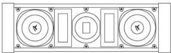
natural_image
Pure electrical circuit lines without any symbolsFigure 1. The Voyage is designed for both vertical and horizontal installation.
Required tools (included):
4mm Allen bit
(2) Push pins
Required tools (not included):
Stud finder
Sharp pencil or pen
Level
Dry wall knife/saw
Wire strippers
Electric drill (with clutch)
Tape measure
Depth required behind wall surface:
3 3/4" (9.5cm)
Required wall opening (includes tolerance):
9 1/8" x 34 5/16" (23.2cm x 87.2cm)

Figure 2. The Voyage is designed to mount anywhere between studs.

Figure 3. Side view.

Figure 4. Top view.
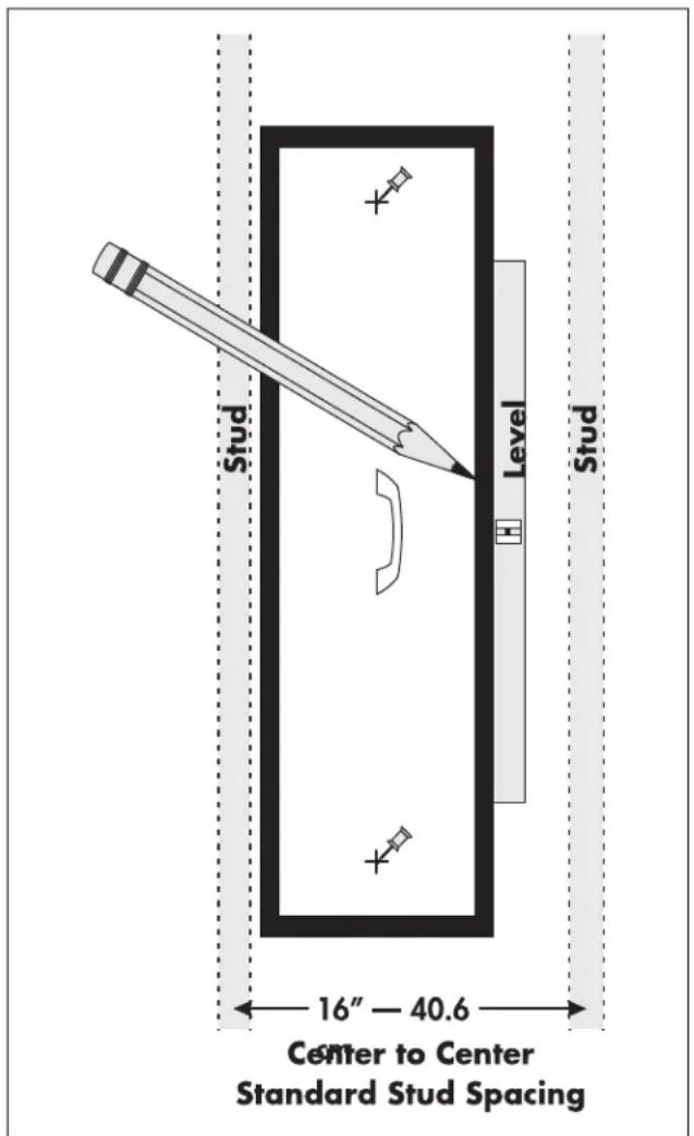
Figure 5. Installation steps 1–3.
1 Using a stud finder, locate the final speaker position between studs.

WARNING! Absolutely no part of the template should overlap a stud.
2 Insert top push pin (provided). Level template. Insert bottom pushpin (provided). Recheck level.
3 Mark cutout through slots in template. Remove Template.
natural_image
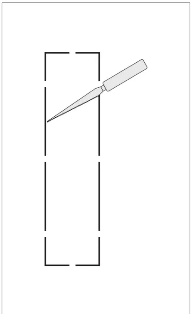
Simple line drawing of a tool hitting a square with dashed lines, no text or symbols presentFigure 6. Installation step 4.
4 Use a dry wall knife/saw to cut out the opening.

Figure 7. Installation step 5.
5 If the tweeter is above or below ear level, position the marked woofer closest to ear level (see sticker on the back of speaker).

natural_image
Technical line drawing of a mechanical assembly with a black cable inserted into a circular component (no text or symbols)Figure 8. Installation step 6.
6 Connect speaker cable. Be consistent when connecting speaker leads to the terminals on the back of the Voyage. Take great care to assign the same color to the (+) terminal on both the speaker and the amplifier.

WARNING! Turn your amplifier off before making or breaking any signal connections!

natural_image
Technical diagram of a multi-tiered mechanical device with circular components and mounting holes, shown with directional arrows (no text or symbols)Figure 9. Installation step 7.
natural_image
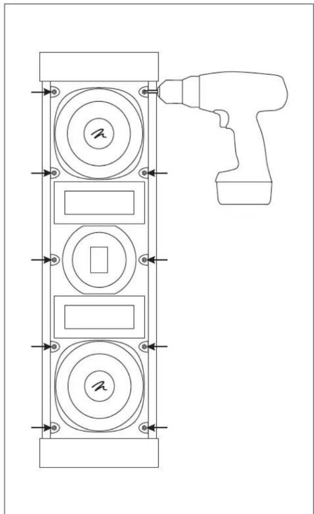
Technical line drawing of a vertical mechanical component with circular and rectangular features, featuring a hand tool inserted (no text or symbols)Figure 10. Installation step 8.
7 Place speaker in hole. 8 Use a 4mm Allen bit (provided) and an electric drill to
lock all 10 mounting locks in place. Use a low clutch setting on the drill.

natural_image
Diagram of a person lying down with two hanging objects and dashed lines indicating motion or force directions (no text or symbols)Figure 11. Installation step 9.
9 Aim the tweeter toward the primary listening position by gently pushing the edge of the tweeter globe (which is capable of 20^ tilt in all directions).
The Voyage tweeter should always be orientated so that the long dimension of the tweeter is vertical (see tweeter position in figure 1). To accommodate both horizontal and vertical orientations, the tweeter globe can rotate 90°.

WARNING! Do not turn the tweeter more than 90° in either direction. Turning the tweeter globe too much may cause wires to disconnect.

natural_image
Technical line drawing of a mechanical component with circular cutouts and mounting brackets (no text or symbols)Figure 12. Installation step 10.
10 Gently bend the grill cover into place.

WARNING! These instructions are written based on commonly available IR repeaters that mount in a 1/2" diameter hole. Before beginning this installation, please refer to the instructions that came with your IR repeater to verify this hole size. If your IR repeater requires a hole size other than 1/2" diameter, adjust these instructions accordingly. Before drilling the mounting hole, a 1/8" pilot hole should always be drilled from the back regardless of the final mounting hole diameter.
Required tools (not included):
Electric drill
1/8" drill bit
1/2" drill bit
1 Prepare a flat surface with a cushion and/or blanket to protect the Voyage. Place the Voyage driver side down.

WARNING! Be careful to put no weight on the tweeter globe.
2 From the rear of the speaker and at the location shown in figure 13, use a 1/8" drill bit to drill a pilot hole.
3 Turn the Voyage over so that it is driver side up.
4 From the front of the speaker, use a 1/2" drill bit to widen the hole for the IR repeater.
5 Follow the instructions that come with the IR repeater to finish installation.

natural_image
Technical line drawing of a mechanical component with two circular flanges and a black arrow indicating direction (no text or symbols)Figure 13. Installing an IR repeater—location to drill hole.

natural_image
Technical line drawing of a computer drive with screw fasteners and fan assembly (no text or symbols)Figure 14. Removing the end caps step 2.

natural_image
Technical line drawing of a mechanical fan assembly with mounting brackets and internal blades (no text or symbols)Figure 15. Removing the end caps step 3.
Required tools (not included):
Philips head screwdriver
1 Prepare a flat surface with a cushion and/or blanket to protect the Voyage. Place the Passage driver side down.

WARNING! Be careful to put no weight on the tweeter globe.
2 Using a Phillips head screwdriver remove 2 screws from the back/bottom of the Voyage (see figure 14).
3 Using a Phillips head screwdriver remove three screws from the bottom edge of the Voyage (see figure 15).
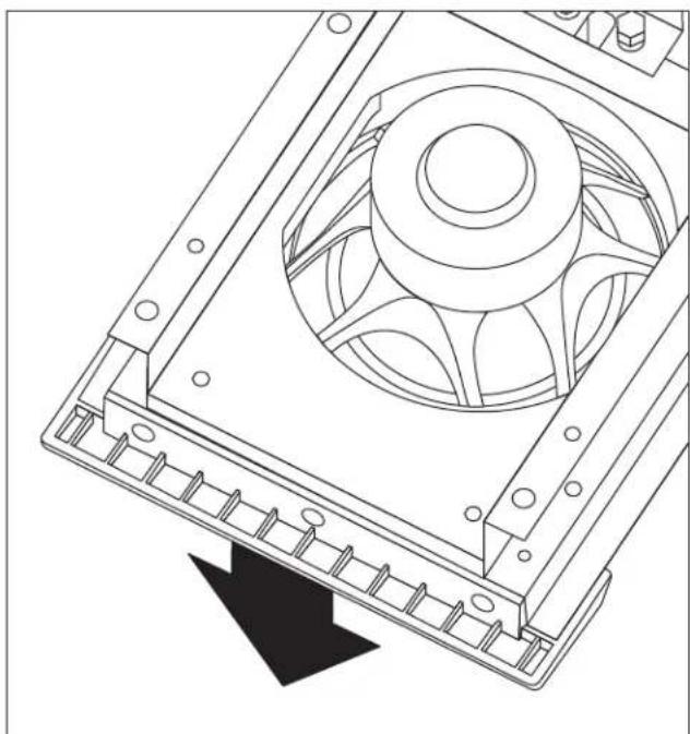
4 The end cap may now be safely removed (see figure 16).
Repeat steps 2–4 to remove other end cap.
natural_image
Technical line drawing of a mechanical fan assembly with a downward arrow indicating motion (no text or symbols)Figure 16. Removing the end caps step 4.
ATF Operation
The MartinLogan ATF transducer (based on RADIA planar technology) consists of a micro-thin, low-mass Kaladex diaphragm with an ultra-light, etched conductive aluminum surface suspended between two high field strength neodymium super magnet arrays (see figure 17). When an electrical current (music signal) passes through the etched aluminum on the diaphragm's surface it is simultaneously pulled towards one of the neodymium arrays and pushed away from the opposing array. When the direction of current is reversed the diaphragm is simultaneously pushed and pulled in the opposite direction, thus producing sound.
Extremely Low-Mass Diaphragm
-Blazing Speed and Inner Detail
Low-mass diaphragms are crucial to a loudspeaker's ability to accurately reproduce sound. As the mass of a transducer's diaphragm decreases, its ability to resolve detail increases. With extremely low-mass characteristics, the ATF transducer tracks the audio signal with almost perfect accuracy.
MartinLogan ATF diaphragms are constructed of extremely low mass Dupont Kaladex® PEN (polyethylene naphthalate)—a material chemically similar to the low-mass PET (polyethylene terathylate) film used in MartinLogan's generation 2 electrostatic transducers, yet capable of handling the high thermal requirements required for stable magnetic thin film operation.
High Field Strength
—Superb Control and Efficiency
With a field strength almost 2000% more powerful than traditional systems, Neodymium iron boron (NIB) rare-earth super magnets are one of the world's strongest commercially available magnetic materials. This incredible field strength proves ideal for maintaining perfect control over the low-mass Kaladex diaphragm. Super-low distortion levels, high-resolution, and crystal-clear transparency are just a few of the benefits resulting from this superb combination of low-mass diaphragm and high field strength.
Push-Pull Operation = Ideal Linearity
Linearity is another factor contributing to a loudspeaker's ability to achieve ultimate clarity, detail and resolution. By positioning neodymium magnet arrays in a push-pull configuration, MartinLogan ATF transducer technology maintains uniform diaphragm control, regardless of position as it traverses the entire audio signal. The push-pull concept is a major contributor to the linearity and sonic superiority of ATF transducers.
Direct Full-Surface Drive
Provides Outstanding Clarity
Unlike traditional voice coil driven systems, ATF diaphragms are directly and uniformly driven throughout their entire surface. This full-surface drive system results in ultra-fast transient response with no cone break up and the ability to accurately reproduce sound with great delicacy, nuance and clarity.
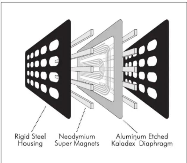
Figure 17. Cut away view of an ATF transducer. Note the simplicity due to minimal part usage.
Frequently Asked Questions Troubleshooting
How do I clean my speakers?
Just use a dust free cloth or a soft brush to remove the dust from your speakers. We recommend a specialty cloth (available at the Xstatic shop at www.martinlogan.com) that cleans your speakers better than anything else we have tried. Do not spray any kind of cleaning agent on or in close proximity to the ATF element.
What size amplifier should I use?
We recommend an amplifier with 100 watts per channel for most applications. Probably less would be adequate when used in home theater where a subwoofer is employed. Our hybrid designs will perform well with either a tube or transistorized amplifier, and will reveal the sonic character of either type. However, it is important that the amplifier be stable operating into varying impedance loads: a stable amplifier will be able to deliver twice its rated wattage into 4 Ohms and should again double into 2 Ohms.
Could you suggest a list of suitable electronics and cables that would be ideal for MartinLogan speakers?
The area of electronics and cable choice is probably the most common type of question that we receive. It is also the most subjective. We have repeatedly found that brands that work well in one setup will drive someone else nuts in another. We use many brands with great success. Again, we have no favorites; we use electronics and cables quite interchangeably. We would suggest listening to a number of brands—and above all else—trust your ears. Dealers are always the best source for information when purchasing additional audio equipment or cables and will be well versed in the subject of special safety requirements for in-wall cable.
Will exposure to sunlight affect the life or performance of my speakers?
We recommend that you not place any loudspeaker in direct sunlight. The ultraviolet (UV) rays from the sun can cause deterioration of grill cloth, speaker cones, etc. Small exposures to UV will not cause a problem. In general, the filtering of UV rays through glass will greatly reduce the negative effects.
Output
- Check that all your system components are turned on.
- Check your speaker wires and connections.
- Check all interconnecting cables.
System Frequency Response
40–20,000 Hz ± 3 dB
Sensitivity
91 dB/2.83 volts/meter (mounted on wall)
Impedance
5 ohms
Crossover Frequency
350, 3000 Hz
Components
Air core coils, polypropelene, metal film and low dissipation electrolytic capacitors
Woofer Type
Two 8" (20.3cm) magnetically shielded high rigidity alum- num cones with extended throw drive assembly
ATF Mid-Range Drivers
Two 1.5" x 6" (3.8cm x 15.2cm) ATF Transducers
ATF High Frequency Driver
1.5" x 2.25" (3.8cm x 5.7cm) ATF Transducer
ATF High Frequency Driver Range of Motion
20^ tilt in all directions. 90^ rotation.
Power Handling
200 watts
Weight
25.5 lbs. each (11.6 kg)
Overall Size
10.5" inches W × 5.625" inches D × 35.875" inches H
(26.7cm W × 14.3cm D × 91.1cm H)
Required wall opening (includes tolerance)
9.125" x 34.3125" (23.2cm x 87.2cm)
Projection from wall surface
1.875" (4.8cm)
Depth required behind wall surface
3.75" (9.6cm)
Warranty and RegistrationSpecification
Your Voyage speaker is provided with an automatic Limited 90 Day Warranty coverage.
You have the option, at no additional charge, to receive a Limited 5 Year Warranty coverage. To obtain the Limited 5 Year Warranty coverage you need to complete and return the Certificate of Registration, included with your speakers, and provide a copy of your dealer receipt to MartinLogan within 30 days of purchase.
For your convenience MartinLogan also offers online warranty registration at www.martinlogan.com.
MartinLogan may not honor warranty service claims unless we have a completed Warranty Registration on file!
If you did not receive a Certificate of Registration with your new Voyage speaker, you cannot be assured of having received new units. If this is the case, please contact your authorized MartinLogan dealer.
Service
Should you be using your MartinLogan product in a country other than the one in which it was originally purchased, we ask that you note the following:
1 The appointed MartinLogan distributor for any given country is responsible for warranty servicing only on units distributed by or through it in that country in accordance with its applicable warranty.
2 Should a MartinLogan product require servicing in a country other than the one in which it was originally purchased, the end user may seek to have repairs performed by the nearest MartinLogan distributor, subject to that distributor's local servicing policies, but all cost of repairs (parts, labor, transportation) must be born by the owner of the MartinLogan product.
3 If, after owning your speakers for six months, you relocate to a country other than the one in which you purchased your speakers, your warranty may be transferable. Contact MartinLogan for details.
AC. Abbreviation for alternating current.
Active crossover. Uses active devices (transistors, ICs, tubes) and some form of power supply to operate.
Amplitude. The extreme range of a signal. Usually measured from the average to the extreme.
Arc. The visible sparks generated by an electrical discharge.
ATF. The abbreviation for advanced thin film.
Bass. The lowest frequencies of sound.
Bi-Amplification. Uses an electronic crossover, or line-level passive crossover, and separate power amplifiers for the high and low frequency loudspeaker drivers.
Capacitance. That property of a capacitor which determines how much charge can be stored in it for a given potential difference between its terminals, measured in farads, by the ratio of the charge stored to the potential difference.
Capacitor. A device consisting of two or more conducting plates separated from one another by an insulating material and used for storing an electrical charge. Sometimes called a condenser.
Clipping. Distortion of a signal by its being chopped off. An overload problem caused by pushing an amplifier beyond its capabilities. The flat-topped signal has high levels of harmonic distortion which creates heat in a loudspeaker and is the major cause of loudspeaker component failure.
CLS. The abbreviation for curvilinear linesource.
Crossover. An electrical circuit that divides a full bandwidth signal into the desired frequency bands for the loudspeaker components.
dB (decibel). A numerical expression of the relative loudness of a sound. The difference in decibels between two sounds is ten times the Base 10 logarithm of the ratio of their power levels.
DC. Abbreviation for direct current.
Diffraction. The breaking up of a sound wave caused by some type of mechanical interference such as a cabinet edge, grill frame or other similar object.
Diaphragm. A thin flexible membrane or cone that vibrates in response to electrical signals to produce sound waves.
Distortion. Usually referred to in terms of total harmonic distortion (THD) which is the percentage of unwanted harmonics of the drive signal present with the wanted signal. Generally used to mean any unwanted change introduced by the device under question.
Driver. See transducer.
Dynamic Range. The range between the quietest and the loudest sounds a device can handle (often quoted in dB).
Efficiency. The acoustic power delivered for a given electrical input. Often expressed as decibels/watt/meter (dB/w/m).
ESL. The abbreviation for electrostatic loudspeaker.
Headroom. The difference, in decibels, between the peak and RMS levels in program material.
Hybrid. A product created by the marriage of two different technologies. Meant here as the combination of a dynamic woofer with an electrostatic or ATF transducer.
Hz (Hertz). Unit of frequency equivalent to the number of cycles per second.
Imaging. To make a representation or imitation of the original sonic event.
Impedance. The total opposition offered by an electric circuit to the flow of an alternating current of a single frequency. It is a combination of resistance and reactance and is measured in ohms. Remember that a speaker's impedance changes with frequency, it is not a constant value.
Inductance. The property of an electrical circuit by which a varying current in it produces a varying magnetic field that introduces voltages in the same circuit or in a nearby circuit. It is measured in henrys.
Inductor. A device designed primarily to introduce inductance into an electrical circuit. Sometimes called a choke or coil.
Linearity. The extent to which any signal handling process is accomplished without amplitude distortion.
Midrange. The middle frequencies where the ear is the most sensitive.
NAC. The abbreviation for natural ambience compensation.
Passive crossover. Uses no active components (transistors, ICs, tubes) and needs no power supply (AC, DC, battery) to operate. The crossover in a typical loudspeaker is of the passive variety. Passive crossovers consist of capacitors, inductors and resistors.
Phase. The amount by which one sine wave leads or lags a second wave of the same frequency. The difference is described by the term phase angle. Sine waves in phase reinforce each other; those out of phase cancel.
Pink noise. A random noise used in measurements, as it has the same amount of energy in each octave.
Polarity. The condition of being positive or negative with respect to some reference point or object.
RMS. Abbreviation for root mean square. The effective value of a given waveform is its RMS value. Acoustic power is proportional to the square of the RMS sound pressure.
Resistance. That property of a conductor by which it opposes the flow of electric current, resulting in the generation of heat in the conducting material, usually expressed in ohms.
Resistor. A device used in a circuit to provide resistance.
Resonance. The effect produced when the natural vibration frequency of a body is greatly amplified by reinforcing vibrations at the same or nearly the same frequency from another body.
Sensitivity. The volume of sound delivered for a given electrical input.
Stator. The fixed part forming the reference for the moving diaphragm in a planar speaker.
THD. The abbreviation for total harmonic distortion. (See Distortion)
TIM. The abbreviation for transient intermodulation distortion.
Transducer. Any of various devices that transmit energy from one system to another, sometimes one that converts the energy in form. Loudspeaker transducers convert electrical energy into mechanical motion.
Transient. Applies to that which lasts or stays but a short time. A change from one steady-state condition to another.
Tweeter. A small drive unit designed to reproduce only high frequencies.
Wavelength. The distance measured in the direction of progression of a wave, from any given point characterized by the same phase.
White noise. A random noise used in measurements, as it has the same amount of energy at each frequency.
Woofer. A drive unit operating in the bass frequencies only. Drive units in two-way systems are not true woofers but are more accurately described as being mid/bass drivers.

MARTIN LOGAN
the loudspeaker technology company
- Contents Introduction
- Congratulations! You have invested in a new world of high performance audio!
- WARNING!
- Placement
- Horizontal Installation
- Installing the Voyage
- Required tools (included):
- Required tools (not included):
- Depth required behind wall surface:
- Required wall opening (includes tolerance):
- ATF Operation
- Extremely Low-Mass Diaphragm
- -Blazing Speed and Inner Detail
- High Field Strength
- —Superb Control and Efficiency
- Push-Pull Operation = Ideal Linearity
- Direct Full-Surface Drive
- Provides Outstanding Clarity
- Frequently Asked Questions Troubleshooting
- How do I clean my speakers?
- What size amplifier should I use?
- Could you suggest a list of suitable electronics and cables that would be ideal for MartinLogan speakers?
- Will exposure to sunlight affect the life or performance of my speakers?
- Output
- System Frequency Response
- Sensitivity
- Impedance
- Crossover Frequency
- Components
- Woofer Type
- ATF Mid-Range Drivers
- ATF High Frequency Driver
- ATF High Frequency Driver Range of Motion
- Power Handling
- Weight
- Overall Size
- Required wall opening (includes tolerance)
- Projection from wall surface
- Depth required behind wall surface
- Warranty and RegistrationSpecification
- Service
Brand : Martin Logan
Model : Voyage
Category : Speaker