
APS15 - Scale Cardinal Detecto - Free user manual and instructions
Find the device manual for free APS15 Cardinal Detecto in PDF.

| Product Type | Digital Scale |
| Brand | Cardinal Detecto |
| Model | APS15 |
| Capacity | 15 kg (33 lb) |
| Readability | 5 g (0.01 lb) |
| Platform Size | 14 x 10 inches (356 x 254 mm) |
| Display | LCD, backlit |
| Power Supply | AC adapter (included) or 6 x AA batteries |
| Units of Measure | kg, g, lb, oz |
| Tare Function | Yes |
| Auto-Off | Yes, programmable |
| Calibration | Manual with external weights |
| Overload Protection | Yes |
| Low Battery Indicator | Yes |
| Construction | Stainless steel platform, ABS housing |
| Operating Temperature | 32°F to 104°F (0°C to 40°C) |
| Net Weight | 3.5 lb (1.6 kg) |
| Dimensions (W x D x H) | 15 x 12 x 3.5 inches (381 x 305 x 89 mm) |
| Included Accessories | AC adapter, instruction manual |
| Certifications | NTEP, CE |
Frequently Asked Questions - APS15 Cardinal Detecto
User questions about APS15 Cardinal Detecto
0 question about this device. Answer the ones you know or ask your own.
Ask a new question about this device
Download the instructions for your Scale in PDF format for free! Find your manual APS15 - Cardinal Detecto and take your electronic device back in hand. On this page are published all the documents necessary for the use of your device. APS15 by Cardinal Detecto.
USER MANUAL APS15 Cardinal Detecto
Setup and Operation Manual
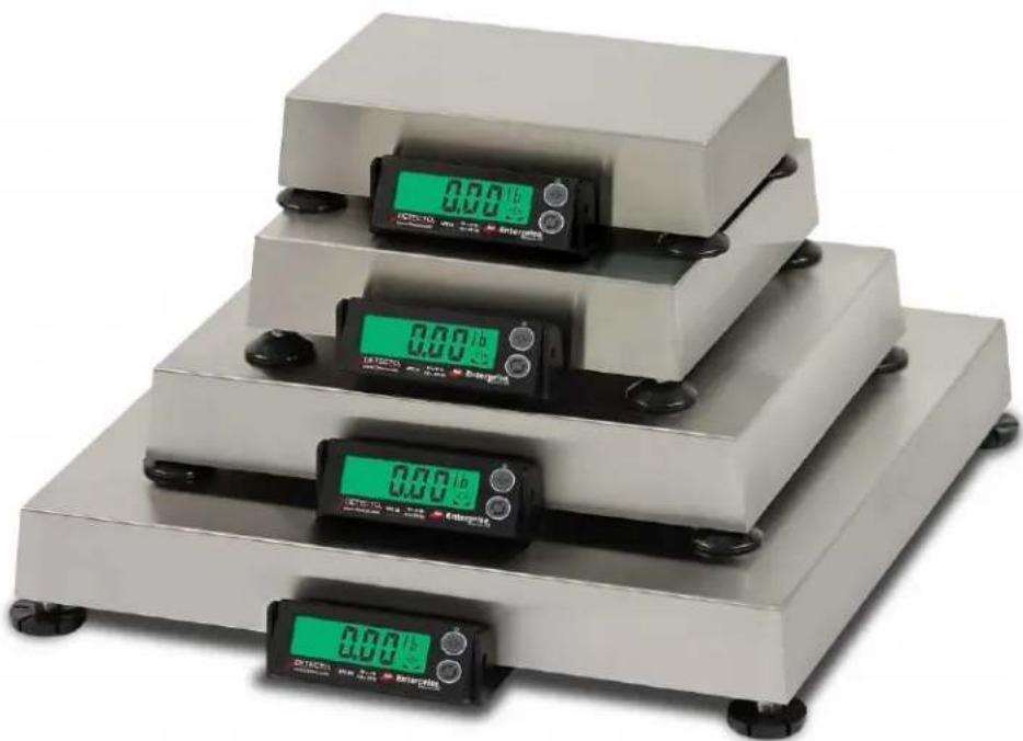
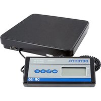
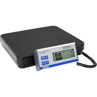
natural_image
Four digital pressure scales with green and black buttons, arranged in a tiered arrangement (no visible text or symbols)
CARDINAL SCALE MFG. CO.
8527-0544-2M Rev E
01/15
PO BOX 151 • WEBB CITY, MO 64870
PH (417) 673-4631 • FAX (417) 673-5001
www.detectoscale.com
Printed in USA
TABLE OF CONTENTS
SPECIFICATIONS Page 1
Options Page 1
Certifications Page 1
SITE PREPARATION REQUIREMENTS Page 2
Site Requirements Page 2
Environmental Conditions Page 2
Electrical Power Page 3
Electrical Noise Interference Page 3
Transient Suppression Page 3
RFI Immunity Page 3
INSTALLATION Page 4
ALL MODELS EXCEPT APS250 Page 4
Unpacking Page 4
Level Adjustment Page 4
APS250 ONLY Page 5
Unpacking and Setup Page 5
Level Adjustment Page 6
Interconnections Page 7
Data Cable Installation Page 7
Scale Display/Serial Port 1 Page 7
Remote Display/Serial Port 2 Page 7
POS/Serial Port 3 Page 7
USB Cable Installation Page 7
Power Adapter Page 7
Serial Data Cable, 8527-0545-0A Page 8
KEYPAD FUNCTIONS ...... Page 9
ANNUNCIATORS Page 9
SETUP AND CONFIGURATION Page 10
To Enter Setup Page 10
TYPE (Scale Type) Page 10
UnS (Motion Range) Page 11
F, L E E r (Adjustable Digital Filtering) Page 11
CAL 16 (Calibration) Page 11
Port 1 (Serial Port 1) Page 12
Port2 (Serial Port 2) Page 12
Port 3 (Serial Port 3) Page 12
USB (USB Port) Page 12
H rES (High Resolution Weight Mode) Page 13
btd,5 (Button Disable) Page 13
ERROR AND STATUS DISPLAYS Page 13
CARE AND CLEANING Page 14
SECURITY SEAL INSTALLATION Page 14
APSRD (REMOTE DISPLAY) Page 15
PARTS IDENTIFICATION Page 16
ALL MODELS EXCEPT APS250 Page 16
APS250 ONLY Page 20
SCALE DISPLAY AND APSRD (REMOTE DISPLAY) Page 24
SERIAL NUMBER
DATE OF PURCHASE
PURCHASED FROM
RETAIN THIS INFORMATION FOR FUTURE USE
PRECAUTIONS
Before using this scale, read this manual and pay special attention to all
"NOTIFICATION" symbols:

IMPORTANT

ELECTRICAL
WARNING
INTRODUCTION
Thank you for selecting and purchasing the Detecto APS Enterprise Scale. It was built with Detecto quality and reliability at our factory in Webb City, Missouri and incorporates the latest in digital technology and innovative features for the weighing industry.
This manual is provided to guide you through installation, setup/calibration and operation of the Detecto APS Enterprise Scale. Please read it thoroughly before attempting to install the scale and keep it handy for future reference.
FCC COMPLIANCE STATEMENT
This equipment generates uses, can radiate radio frequency, and if not installed and used in accordance with the instruction manual, may cause interference to radio communications. It has been tested and found to comply with the limits for a Class A computing device pursuant to Subpart J of Part 15 of FCC rules, which are designed to provide reasonable protection against such interference when operated in a commercial environment. Operation of this equipment in a residential area may cause interference in which case the user will be responsible to take whatever measures necessary to correct the interference.
You may find the booklet "How to Identify and Resolve Radio TV Interference Problems" prepared by the Federal Communications Commission helpful. It is available from the U.S. Government Printing Office, Washington, D.C. 20402, stock No. 001-000-00315-4.
COPYRIGHT
All rights reserved. Reproduction or use, without expressed written permission, of editorial or pictorial content, in any manner, is prohibited. No patent liability is assumed with respect to the use of the information contained herein.
DISCLAIMER
While every precaution has been taken in the preparation of this manual, the Seller assumes no responsibility for errors or omissions. Neither is any liability assumed for damages resulting from use of the information contained herein. All instructions and diagrams have been checked for accuracy and ease of application; however, success and safety in working with tools depend to a great extent upon the individual accuracy, skill and caution. For this reason, the Seller is not able to guarantee the result of any procedure contained herein. Nor can they assume responsibility for any damage to property or injury to persons occasioned from the procedures. Persons engaging the procedures do so entirely at their own risk.
PROPER DISPOSAL
When this device reaches the end of its useful life, it must be properly disposed of. It must not be disposed of as unsorted municipal waste. Within the European Union, this device should be returned to the distributor from where it was purchased for proper disposal. This is in accordance with EU Directive 2002/96/EC. Within North America, the device should be disposed of in accordance with the local laws regarding the disposal of waste electrical and electronic equipment.
It is everyone's responsibility to help maintain the environment and to reduce the effects of hazardous substances contained in electrical and electronic equipment on human health. Please do your part by making certain that this device is properly disposed of. The symbol shown to the right indicates that this device must not be disposed of in unsorted municipal waste programs.

SPECIFICATIONS
| Model | Platform Size | Capacity | Increments | Divisions | Load Cell |
| APS8 | 6 in x 10 in15 cm x 25 cm | 15 lb | 0.01 lb | 1500 | TSP-10kg |
| 7.5 kg | 0.005 kg | 1500 | |||
| APS10 | 6 in x 10 in15 cm x 25 cm | 30 lb | 0.01 lb | 3000 | TSP-15kg |
| 15 kg | 0.005 kg | 3000 | |||
| APS12 | 6 in x 10 in15 cm x 25 cm | 160 oz | 0.1 oz | 1600 | TSP-10kg |
| APS160 | 10 in x 10 in25 cm x 25 cm | 160 oz | 0.1 oz | 1600 | TSP-10kg |
| APS15 | 10 in x 10 in25 cm x 25 cm | 15 lb | 0.01 lb | 1500 | TSP-10kg |
| 7.5 kg | 0.005 kg | 1500 | |||
| APS20 | 10 in x 10 in25 cm x 25 cm | 30 lb | 0.01 lb | 3000 | TSP-15kg |
| 15 kg | 0.005 kg | 3000 | |||
| APS30 | 12 in x 14 in31 cm x 36 cm | 30 lb | 0.01 lb | 3000 | TSP-15kg |
| 15 kg 0.005 kg 3000 | |||||
| APS70 | 12 in x 14 in31 cm x 36 cm | 70 lb | 0.02 lb | 3500 | TSP-30kg |
| 31 kg | 0.01 kg | 3500 | |||
| APS150 | 12 in x 14 in31 cm x 36 cm | 150 lb | 0.05 lb | 3000 | TSP-100kg |
| 60 kg | 0.02 kg | 3000 | |||
| APS250 | 18 in x 18 in46 cm x 46 cm | 250 lb | 0.1 lb | 2500 | TSP-100kg |
| 113 kg 0.05 kg 2500 | |||||
| Power Requirements: | 100 to 240 VAC 50/60Hz 12 VDC 1A wall plug-in UL/CSA listed AC power adapter (Cardinal part number 6800-1045) |
| Operating Environment: | Temperature Range: 14^ to 104^ F ( -10^ to +40^ C) |
| Display: | Five digit, seven segment, 0.875 inch (22 mm) high LCD |
| Interfaces: | 2 RS-232 serial, 1 USB-B, 1 OPOS compatible serial, most POS system protocols included (Cardinal Scale/SMA, Avery Berkel, NCI/Worldship, Mettler PS, Mettler SICS) |
Options
• APSWIFI – APS Wi-Fi
• APSRD – Remote Display w/6ft. cable
• APSFS – Foot Switch Zero
• APSPOST – Remote Display Tower
• APSPB – Push Button Zero
• BT1214 / BT1818 – Ball Top Transfer
Certifications
This equipment is certified to comply with the requirements for a Class III device by the National Conference on Weights and Measurements (Certificate Number: 14-057).

SITE PREPARATION REQUIREMENTS
The Detecto APS Enterprise Scale is a precision weight-measuring instrument. As with any precision instrument, they require an acceptable environment to operate at peak performance and reliability. This section is provided to assist you in obtaining such an environment.
Site Requirements
In order to keep cooling requirements to a minimum, the indicator should be placed out of direct sunlight and to provide adequate air circulation, keep the area around the indicator clear.

natural_image
Illustration of a desk with a computer monitor displaying a sun and books, no text or symbols present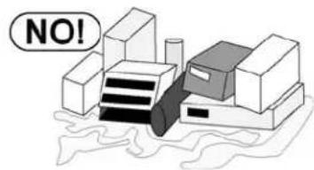
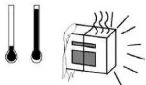
Make certain the indicator is not directly in front of a heating or cooling vent. Such a location will subject the indicator to sudden temperature changes, which may result in unstable weight readings.

natural_image
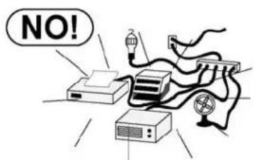
Illustration of a thermometer and a steaming box with heat lines, no text or symbols presentInsure that the indicator has good, clean AC power and is properly grounded. In areas subject to lightning strikes, additional protection to minimize lightning damage, such as surge suppressors, should be installed.
natural_image
Simple line drawing of a device emitting a lightning bolt (no text or symbols)Environmental Conditions
The APS Enterprise scale has been designed to operate under the following environmental conditions:
- Indoor use only.
- Ambient temperature range of 14 to 104^ (-10 to +40 °C
- Main supply voltage fluctuations not to exceed ± 10% of the nominal voltage.
- Transient overvoltage's according to Installation Categories II (Overvoltage Categories per IEC 1010). Temporary voltage spikes on the AC input line that may be as high as 1500V for 115V models and 2500V for 230V models are allowed.
- Used in an environment of Pollution degrees 2 (i.e., where normally only non-conductive atmospheres are present). Occasionally, however, a temporary conductivity caused by condensation must be expected, in accordance with IEC 664.
SITE PREPARATION REQUIREMENTS, CONT.
Electrical Power
The APS Enterprise scale is powered by a 100 to 240 VAC 50/60Hz 12 VDC 1A wall plug-in UL/CSA listed AC power adapter. Note that a special order is not required for operation at 230/240 VAC.
- The socket-outlet supplying power to the scale should be on a separate circuit from the distribution panel and dedicated to the exclusive use of the scale.
- The socket-outlet shall be installed near the equipment and shall be easily accessible. Note that the wall plug-in AC power adapter serves as the power disconnect.
- The wiring should conform to national and local electrical codes and ordinances and should be approved by the local inspector to assure compliance.
- On installations requiring 230 VAC power, it is the responsibility of the customer to have a qualified electrician install the proper power adapter plug that conforms to national electrical codes and local codes and ordinances.
Electrical Noise Interference
To prevent electrical noise interference, make certain all other wall outlets for use with air conditioning and heating equipment, lighting or other equipment with heavily inductive loads, such as welders, motors and solenoids are on circuits separate from the scale. Many of these disturbances originate within the building itself and can seriously affect the operation of the scale. These sources of disturbances must be identified and steps must be taken to prevent possible adverse effects on the scale. Examples of available alternatives include isolation transformers, power regulators, uninterruptible power supplies, or simple line filters.
Transient Suppression
The following recommendations will help to reduce transients:
• Always use shielded cables to connect signal wires to the weight scale.
- Do not run signal cables from the scale alongside or parallel to wiring carrying AC power. If unavoidable, position the signal cables a minimum of 24" away from all AC wiring.
- Always use arc suppressors across all AC power relay contacts (see recommendations at http://www.paktron.com/pdf/Quencharch_QRL.pdf).
RFI Immunity
The operation of sensitive electronic equipment can be adversely affected by RF (Radio Frequency) radio transmissions. Digital weight scales are one such type of equipment. Radio transmissions come from things like hand-held radio transmitters and cell phones. One symptom of RFI (Radio Frequency Interference) in a digital weight scale is weight indication instability during a radio transmission.
The APS Enterprise scale was designed with special grounding and RFI shielding to achieve a high degree of immunity to common RFI. To maximize the scale's immunity to radio transmissions, follow these guidelines:
- ALWAYS use shielded cable for all I/O (Input/Output) connections to the scale.
- NEVER operate any radio transmitter within 2 meters (\~6ft.) of the scale.
- NEVER connect un-terminated cables to the scale.
- KEEP the intended external I/O devices connected to I/O cables entering the scale.
- ALWAYS connect the shield of the shielded I/O cable at the scale end only. Leave the shield unconnected at the I/O device.
INSTALLATION
(ALL MODELS EXCEPT APS250)
Unpacking
Remove the scale from the shipping carton. Remove all packing material and then examine the scale to make certain there is no shipping damage. Should damage be discovered contact the shipping company as soon as possible. The packing material and shipping carton should be retained for possible examination by the shipping company.
Determine where the scale is to be located. It should be a smooth surface capable of supporting both the scale and any load to be placed on the scale. It should not be in direct sunlight nor should it be subject to air flow from heating/cooling vents, fans or similar devices. Plug-in the 12VDC adapter to use scale. Refer to Electrical Power section of this manual for more instruction. The scale is now ready for use.
Level Adjustment
Place the scale in the chosen location and remove the stainless steel platform. The platform can be removed by lifting upward on it removing it from the weighbridge. Locate the small level indicator on the scale base to the right of the display and check to make certain that the scale is level.

NOT Bubble within
LEVEL
is
circle
not

LEVEL Bubble is within circle
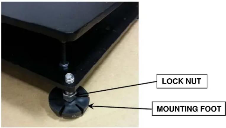
If the level indicator does not show a level indication, the mounting feet should be adjusted to obtain a level condition. To adjust a mounting foot, first loosen the lock nut (located under the scale base) and then turn the mounting foot in the required direction to raise or lower that corner of the scale. Once a level condition has been achieved, secure the mounting foot settings by tightening each of the lock nuts. Replace the platform on the weighbridge.
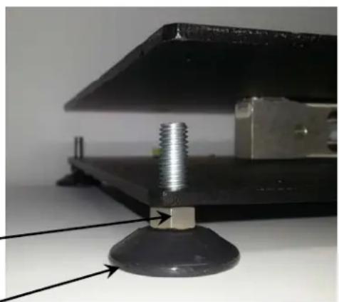
natural_image
Close-up of a mechanical clamp with a threaded screw and base, showing alignment arrows (no text or symbols)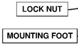
INSTALLATION, CONT.
(APS250 ONLY)
Unpacking and Setup
-
Remove the scale display, hardware pack, power supply, scale cover and scale base assembly from the shipping carton. Remove all packing material and then examine the scale to make certain there is no shipping damage. Should damage be discovered contact the shipping company as soon as possible. The packing material and shipping carton should be retained for possible examination by the shipping company.
-
Remove the four leveling feet from the hardware pack and install in each corner of scale
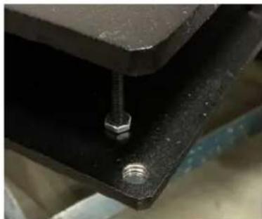
natural_image
Close-up of a metal bracket with a bolt inserted, showing bolt holes and a small nut (no text or symbols visible)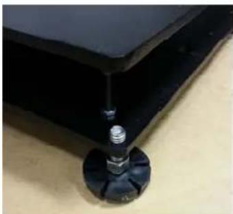
natural_image
Close-up of a mechanical component with a screw and threaded shaft inserted into a black plate (no visible text or symbols)base as shown. NOTE: Leveling feet must be in place to operate the scale.
-
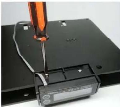
To mount the display on the scale base, use the two included mounting screws in the hardware pack.
-
Insert the screws through the two holes in the scale display bracket and attach the bracket to the scale base.
natural_image
Close-up of a mechanical device with a screwdriver inserted into a black base, showing wiring and a digital display (no visible text or symbols)- Route the cable into the scale and plug into scale display port (see interconnection section for port location and more information).

natural_image
Black rectangular electronic device with attached cable and two circular ends (no visible text or symbols)INSTALLATION, CONT.
(APS250 ONLY)
Unpacking and Setup, Cont.
- Determine where the scale is to be located. It should be a smooth surface capable of supporting both the scale and any load to be placed on the scale. It should not be in direct sunlight nor should it be subject to air flow from heating/cooling vents, fans or similar devices.
- Plug-in 12VDC adapter to use scale. Refer to Electrical Power section of this manual for more instruction.
- The scale is now ready for use.
Level Adjustment
Place the scale in the chosen location and remove the stainless steel platform. The platform can be removed by lifting upward on it removing it from the weighbridge. Locate the small level indicator on the scale base to the right of the display and check to make certain that the scale is level.

NOT Bubble within
LEVEL
is
circle
not
LEVEL Bubble is within circle
If the level indicator does not show a level indication, the mounting feet should be adjusted to obtain a level condition. To adjust a mounting foot, first loosen the lock nut (located under the scale base) and then turn the mounting foot in the required direction to raise or lower that corner of the scale. Once a level condition has been achieved, secure the mounting foot settings by tightening each of the lock nuts. Replace the platform on the weighbridge.
INSTALLATION, CONT.
Interconnections
All input, output and power connections to the APS Enterprise scale are made internally to the main board inside the scale. Connections for the scale display, remote display and OPOS compatible serial device are made using RJ11 snap-in modular connectors. The USB port is a device (or upstream) port using an industry standard "B" connector. The 12VDC 1A wall plug-in UL/CSA listed AC power adapter is connected using a power jack.
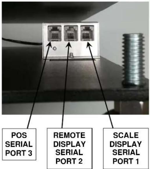
Data Cable Installation
SCALE DISPLAY/SERIAL PORT 1
Plug the RJ11 connector from the Scale Display cable into the scale base as marked.
REMOTE DISPLAY/SERIAL PORT 2
To use a remote display, plug the remote display RJ11 connector into the scale base where marked.
POS/SERIAL PORT 3
NOTE: The included serial data cable uses an RJ11 phone type connector (scale base) to a DB9 connector (OPOS compatible serial device).
Plug the RJ11 connector of the included 4' serial data cable into the scale base where marked and then plug the other end into an available serial port on the POS device.
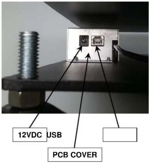
USB Cable Installation
USB
To use the USB interface, obtain an industry standard USB cable and plug it into the scale base where marked and then plug the other end into a USB port on your computer.
Power Adapter
12VDC
To apply power to the scale using the supplied 12VDC 1A wall plug-in UL/CSA listed AC power adapter, insert the plug from the power adapter cable into the power jack on the scale base where marked (refer to previous page) and then plug the power adapter into a proper electrical outlet. The scale is now ready for operation.
INSTALLATION, CONT.
Serial Data Cable, 8527-0545-0A
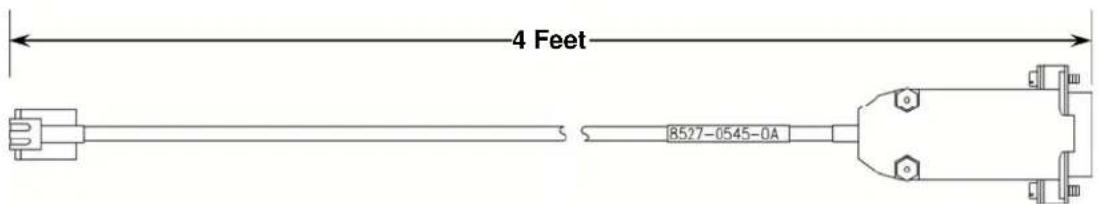
(Included 4' Serial Data Cable, 8527-0545-0A)
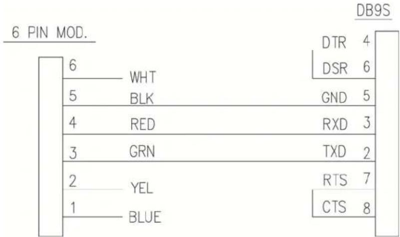
(Wiring Diagram, Serial Data Cable, 8527-0545-0A)
KEYPAD FUNCTIONS


DO NOT operate the keypad with pointed objects (pencils, pens, etc.). Damage to keypad resulting from this practice is NOT covered under warranty.
The keypad of the APS Enterprise Scale has two keys, ZERO (ON/OFF) and UNITS which have the following functions:

This is the ZERO (ON/OFF) key. It serves several purposes. First, when the scale is off, pressing it will turn the scale ON. If the scale is already on, pressing and holding it for approximately 3 seconds will turn the scale OFF.
Pressing this key when the scale is on will zero the scale.

This is the UNITS key. This key is used to change the weighing units to the alternate units of measurement. For example, with pounds displayed, pressing this key will change the weighting units to kilograms.
ANNUNCIATORS
The annunciators are turned on to indicate that the display is in the mode corresponding to the annunciator label or that the status indicated by the label is active.
OZ
This annunciator is turned on to indicate the weight displayed is in ounces.
lb
This annunciator is turned on to indicate that the displayed weight is in pounds.
kg
This annunciator is turned on to indicate the weight displayed is in kilograms.
(STABLE)
This annunciator is turned on when the weight display is stable. When off, it means that the change in successive weight samples is greater than the motion limits selected during setup.
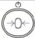
→0←(ZERO)
The (0) annunciator is turned on to indicate that the weight is within +/- 1/4 division of the center of zero.
SETUP AND CONFIGURATION
The keypad of the Enterprise has two keys, ZERO and UNITS which have the following functionality when in setup mode:
ZERO – When a prompt is currently being shown (not the value of the prompt), pressing the ZERO key will skip to the next prompt. If the value of a prompt is being shown, pressing the ZERO key will toggle between the acceptable values for the current prompt.
UNITS – When a prompt is currently being shown (not the value of the prompt), pressing the UNITS key will display the value for that prompt. If the value of a prompt is being shown, then pressing the UNITS key will save the current value and advance to the next setup prompt.
To Enter Setup
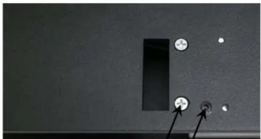
- Remove the Calibration Switch Access screw located on the bottom of the scale base.
- With the scale ON, use a 1/8" or 3 mm Hex Key Wrench or other small tool and press the Calibration Switch.
- The display will change to show EYPE.

natural_image
Close-up of a black electronic device panel with a rectangular slot and two screws, one pointing to a small circular feature (no text or symbols visible)Calibration Switch Access
TYPE (Scale Type)
This will determine the capacity, interval, decimal, and converted units (if applicable).
Press the UNITS key to show current setting. If value displayed is acceptable, press the UNITS key again to save it. Otherwise, press the ZERO key to step through selections for a new value and then press the UNITS key to save it. The following types are selectable for the Enterprise scale:
$$ \begin{array}{l} 1 0 = \text { APS10 } 3 0 \mathrm{lb} \times 0. 0 1 \mathrm{lb} (1 5 \mathrm{kg} \times 0. 0 0 5 \mathrm{kg}) \ 1 5 = \text { APS15 } 1 5 \mathrm{lb} \times 0. 0 1 \mathrm{lb} (7. 5 \mathrm{kg} \times 0. 0 0 5 \mathrm{kg}) \ 3 0 = \text { APS30 } 3 0 \mathrm{lb} \times 0. 0 1 \mathrm{lb} (1 5 \mathrm{kg} \times 0. 0 0 5 \mathrm{kg}) \ 1 5 0 = \text { APS150 } 1 5 0 \mathrm{lb} \times 0. 0 5 \mathrm{lb} (6 0 \mathrm{kg} \times 0. 0 2 \mathrm{kg}) \ 2 5 0 = \text { APS250 } 2 5 0 \mathrm{lb} \times 0. 1 \mathrm{lb} (1 2 5 \mathrm{kg} \times 0. 0 5 \mathrm{kg}) \ 1 6 0 = \text { APS160 } 1 6 0 \text { oz } \times 0. 1 \text { oz } \ 7 0 = \text { APS70 } 7 0 \mathrm{lb} \times 0. 0 2 \mathrm{lb} (3 1 \mathrm{kg} \times 0. 0 1 \mathrm{kg}) \ 2 0 = \text { APS20 } 3 0 \mathrm{lb} \times 0. 0 1 \mathrm{lb} (1 5 \mathrm{kg} \times 0. 0 0 5 \mathrm{kg}) \ 8 = \text { APS8 } 1 5 \mathrm{lb} \times 0. 0 1 \mathrm{lb} (7. 5 \mathrm{kg} \times 0. 0 0 5 \mathrm{kg}) \ 1 2 = \text { APS12 } 1 6 0 \text { oz } \times 0. 1 \text { oz } \ \text { TEST } \quad \text { FACTORY TEST SETTINGS } \ \end{array} $$
SETUP AND CONFIGURATION, CONT.
Un5 (Motion Range)
This is the motion range of the scale, or the number of divisions that the scale weight can change without setting the motion indicator.
Press the UNITS key to show current setting. If value displayed is acceptable, press the UNITS key again to save it. Otherwise, press the ZERO key to step through selections for a new value and then press the UNITS key to save it.
Allowable values are 0 through 9.
F ILtr (Adjustable Digital Filtering)
This is the adjustable digital weight filtering that is applied to the weight in order to help filter out vibrations or other noise that might make the weight unstable.
Press the UNITS key to show current setting. If value displayed is acceptable, press the UNITS key again to save it. Otherwise, press the ZERO key to step through selections for a new value and then press the UNITS key to save it.
Allowable values are Off, 1, 2 or 3.
OFF = No weight filtering
I = Minimal weight filtering
2 = Moderate weight filtering
3 = Maximum weight filtering
CAL 16 (Calibration)
This is the calibration routine for the scale.
With display showing CAL, b, press the UNITS key. The display will change to show current setting no. If scale has been previously calibrated and you wish to skip calibration and proceed to PORT, press the UNITS key again and internal calibration factor will be retained.
To begin calibration, press the ZERO key to select yes and then press the UNITS key. After pressing the UNITS key, the display will change to LORD.
-
With LORD displayed, press the UNITS key. The display will change to show the currently selected scale type's capacity. NOTE: For convenience, you can press the ZERO key and change this to half of capacity.
-
Once the test load weight is selected, placed the test load weight on the scale platform and then press the UNITS key.
-
Starting at the right and proceeding left, a series of dashes will appear on the display and then starting at the left and proceeding right disappear. Next, the display will change to the UnD prompt.
-
Remove all weight from the scale platform and then press the UNITS key.
-
Starting at the right and proceeding left, a series of dashes will appear on the display and then starting at the left and proceeding right disappear. Next, the display will change to the Port I prompt. Calibration is complete. Proceed to Port I.
SETUP AND CONFIGURATION, CONT.
PORT (RS-232 Serial Port 1)
This is the output format for the first serial port. It should default to "SooB" in order to be used with the Enterprise display.
The serial port parameters for this port are fixed at 9600 baud, 8 data bits, 1 stop bit and No parity.
Press the UNITS key to show current setting. If value displayed is acceptable, press the UNITS key again to save it. Otherwise, press the ZERO key to step through selections for a new value and then press the UNITS key to save it.
Options for port output format are as follows:
500R Cardinal/SMA, on-demand type output format
nc, NCI output format
nntPS Mettler Toledo PS output format
ont5, Mettler Toledo SICS output format
LPL Lone Peak Labeling

IMPORTANT! Selecting LPL (Lone Peak Labeling) for the port output format will change the behavior of the scale. When the scale settles on "any" positive weight above zero, the display will lock on that weight until the scale returns to zero.
Port2 (RS-232 Serial Port 2)
This is the second serial port output format selection. It is identical to the P_0 -E I, including the serial port parameters for this port are fixed at 9600 baud, 8 data bits, 1 stop bit and No parity.
Press the UNITS key to show current setting. If value displayed is acceptable, press the UNITS key again to save it. Otherwise, press the ZERO key to step through selections for a new value and then press the UNITS key to save it.
Options for Port2 output format are the same as Port1.
Port3 (POS Serial Port 3 - OPOS Compatible)
This is the third serial port output format selection. NOTE: The serial port parameters for this port are fixed at 9600 baud, 7 data bits, 1 stop bit and Even parity. This is in order to work with most POS systems that require NCI format. NOTE: The default format for this port is NCI.
Press the UNITS key to show current setting. If value displayed is acceptable, press the UNITS key again to save it. Otherwise, press the ZERO key to step through selections for a new value and then press the UNITS key to save it.
USB (USB Port)
The USB port output format selections are similar to the serial port settings. When connected to a PC, this should appear as a virtual com port and can transmit weight using any of the formats listed under PORT 1.
Press the UNITS key to show current setting. If value displayed is acceptable, press the UNITS key again to save it. Otherwise, press the ZERO key to step through selections for a new value and then press the UNITS key to save it.
Options for USB output format are the same as Port 1.
SETUP AND CONFIGURATION, CONT.
H, rES (High Resolution Weight Mode)
The High Resolution Weight Mode feature will display the weight at 10 times the standard resolution. For example, an APS configured for 250 lb x 0.1 lb will display weight in high resolution mode at 250 lb x 0.01 lb.
Press the UNITS key to show current setting. If value displayed is acceptable, press the UNITS key again to save it. Otherwise, press the ZERO key to step through selections for a new value and then press the UNITS key to save it.
Allowable values are YES or no.
$$ \begin{array}{l} \text { YES } = \text { If High Resolution Weight } \ \text { mode is desired } \end{array} $$
$$ \begin{array}{l} \text { no } = \text { High Resolution Weight mode is } \ \text { not desired } \end{array} $$

NOTE: If YES is selected, the scale will exit Setup and Calibration, reset and then display weight in the High Resolution Weight mode.
IMPORTANT! When the scale is in the High Resolution Weight mode, no Units will be displayed and the scale is not Legal For Trade.
To exit the High Resolution Mode, press and hold the ZERO (ON/OFF) key to turn the scale off and then press the ZERO (ON/OFF) to the scale back on
btd,5 (Button Disable)
This setting allows the keypad buttons to be disabled for use by the operator "during normal operation". During normal operation, when the operator presses a disabled button, the button will be ignored.

NOTE: The Button Disable setting only disables the buttons for use during normal operation, not setup and calibration.
Press the UNITS key to show current setting. If value displayed is acceptable, press the UNITS key again to save it. Otherwise, press the ZERO key to step through selections for a new value and then press the UNITS key to save it.
Allowable values are 0, 1, 2 or 3.
$$ \begin{array}{l} 0 = \text { No buttons disabled } \ I = \text { Zero button disabled } \ 2 = \text { Tare button disabled } \ 3 = \text { Both buttons disabled } \ \end{array} $$

NOTE: Disabling the buttons also disables the SMA zero and SMA toggle units commands so this setting may affect Serial/USB port operation if using the SMA commands.
ERROR AND STATUS DISPLAYS
Display
$$ - E r r - $$
$$
$$
Meaning
Displayed when the ZERO key is pressed and the scale could not zero.
Displayed when scale weight exceeds scale capacity, or if there is an analog high/low error.
CARE AND CLEANING
NOTE: The APS Enterprise scale contains no user-serviceable parts and maintenance should be limited to an occasional cleaning as required.
- Do not submerge the scale in water, pour or spray water directly on it to clean. The scale is not waterproof and covering it with water will damage it and void the warranty.
• Always remove power before cleaning. - Do not use wire brushes, abrasives, or cleaning tools such as steel pads and scrapers, which will scratch the surface. Instead, use soft cloths or plastic scouring pads for cleaning.
- When possible use treated water. Hard water can leave behind deposits. Soft water is much gentler on the stainless steel and painted surfaces.
- Avoid the use of acetone, thinner or other volatile solvents and abrasive type cleaners for cleaning. If required, a mild solvent such as mineral spirits can be used to remove oil, grease, tars, wax, and similar substances. Use a cloth dampened with mineral spirits and only apply to areas that are contaminated. Follow up the use of this mild solvent with detergent cleaning and rinsing.
SECURITY SEAL INSTALLATION
If your metrology laws require the use of physical sealing, a lead and wire security seal can be installed on the APS Enterprise scale to prevent the Calibration Switch Access screw located on the bottom of the scale base from being removed to gain access to the calibration switch thereby preventing unauthorized access to the calibration adjustments.
NOTE: In order to install the lead and wire security seal, two screws must be replaced with two drilled screws. They are available from the Cardinal/Detecto Parts Department. The part numbers are:
6021-0605 (SCW FILLISTER. MACHINE-SCW 06-32X.375)
6024-0126 (WASHER FLAT)
6021-1108 (SCW FILLISTER. MACHINE-SCW 10-32X.375)
To install a lead and wire security seal, follow the steps provided below:
- Remove the Calibration Switch Access screw and replace it with the drilled 10-32 screw. Make certain it is securely tighten before proceeding.
- Remove the PCB Cover screw as shown and replace it with the drilled 6-32 screw and flat washer. Make certain it is securely tighten before proceeding.
- Thread the sealing wire through the hole in the drilled screws.
- Pull the wire tight and install the lead seal.
- The screws cannot be removed without damaging the seal.
natural_image
Close-up of a black electrical outlet with two circular buttons and a pointer, no visible text or symbolsPCB Cover Screw
Calibration Switch
Access Screw

natural_image
Close-up of a mechanical component with metallic parts and wires, no visible text or symbols6-32 Screw and Flat Washer
APSRD (REMOTE DISPLAY)
The APSRD (Remote Display) can be mounted using three (3) methods.
- The bracket can be attached to the wall using the appropriate hardware for the type of wall construction.
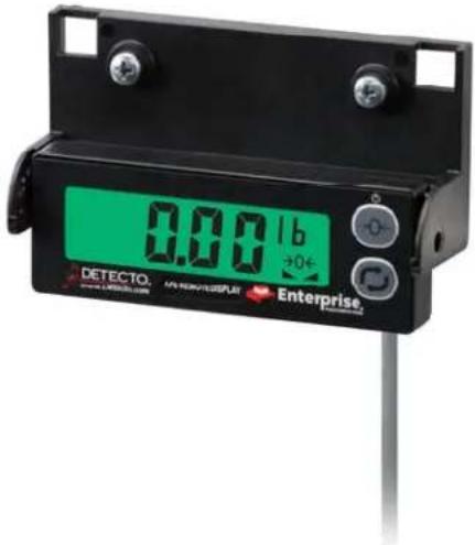
- The remote display can be removed from the bracket and mounted on the wall using the included Velcro® strips.
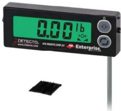
- Using the remote display post, it can be mounted to a table, bench or in a retail environment, the check stand.
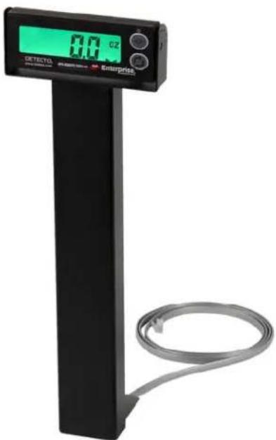
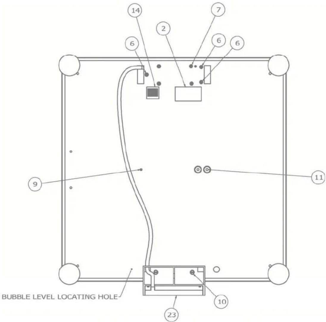
PARTS IDENTIFICATION
(ALL MODEL EXCEPT APS250)
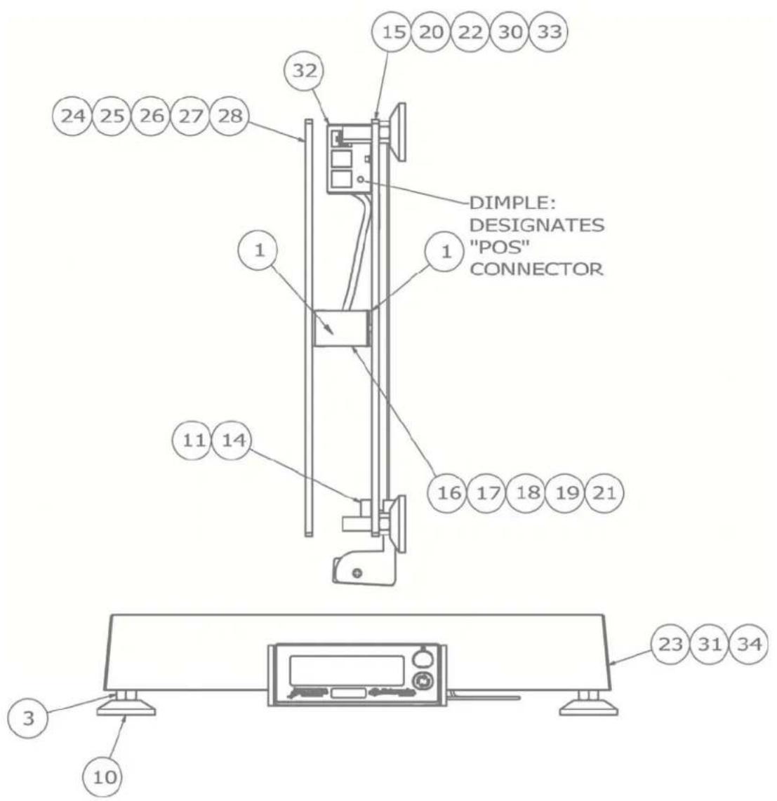
PARTS IDENTIFICATION, CONT.
(ALL MODEL EXCEPT APS250)
| ITEM | PART NO. | QTY | DESCRIPTION |
| 1 | 1960-B465-08 | 2 | SPACER FOR EB-XXX-XXXX |
| 3 | 6013-0077 | 4 | HEX NUT |
| 10 | 6540-1165 4 LEVEL | LING | OOT, 1.63 BASE X 3/8"-16 X 1.3 STUD,BLK PU |
| 11 | 6560-1072 A/R ADHESIVE | VESIVE | LOCTITE 49 |
| 14 | 6690-0001 1 BULLSEYE BUBBLE LEVEL | ||
| 15 | 8527-0519-08 1 BASE PLATE, 30 | ||
| 16 | 8527-0520-0A 1 LOAD CELL ASSY, 10KG (APS160, APS15, APS8, APS12) | ||
| 17 | 8527-0521-0A 1 LOAD CELL ASSY, 15KG (APS10, APS20) | ||
| 18 | 8527-0521-1A 1 LOAD CELL ASSY, 15KG (APS30) | ||
| 19 | 8527-0522-0A 1 LOAD CELL ASSY, 30KG (APS70) | ||
| 20 | 8527-0523-08 1 BASE PLATE, 150 | ||
| 21 | 8527-0524-0A 1 LOAD CELL ASSY, 100KG (APS150) | ||
| 22 | 8527-0527-08 1 BASE PLATE, 70 | ||
| 23 | 8527-0528-08 | 1 | COVER, 12X14 |
| 24 | 8527-0529-08 | 1 | TOP PLATE, 8/10/12 |
| 25 | 8527-0530-08 | 1 | TOP PLATE, 160/15/20 |
| 26 | 8527-0531-08 | 1 | TOP PLATE, 30 |
| 27 | 8527-0532-08 | 1 | TOP PLATE, 70 |
| 28 | 8527-0533-08 | 1 | TOP PLATE, 150 |
| 30 | 8527-C503-08 1 | BASE PLATE, 8/10/12 | |
| 31 | 8527-C504-08 | 1 | COVER, 6X10 |
| 32 | 8527-C505-08 | 1 | PCB COVER |
| 33 | 8527-C513-08 1 | BASE PLATE, 160/15/20 | |
| 34 | 8527-C514-08 | 1 | COVER, 10X10 |
A/R = AS REQUIRED
PARTS IDENTIFICATION, CONT.
(ALL MODEL EXCEPT APS250)
| ITEM | PART NO. | QTY | DESCRIPTION |
| 2 59 | 3GR986 1 SERIAL | TAG ASSY | |
| 5 60 | 21-0625 3 SCW FLAT-HEAD. MACHINE-SCW 06-32X.375 | ||
| 6 60 | 21-0659 4 SCW FLAT-HEAD. MACHINE-SCW 06-32X1.00 | ||
| 7 60 | 21-1069 2 SCW CUP-POINT. SET-SCREW.. 10-32X.25 NYLON PATCH | ||
| 8 60 | 21-1108 2 SCW FILLISTER. MACHINE-SCW 10-32X.375 | ||
| 9 60 | 21-1706 4 SCW FLAT-HEAD. CAP-SCREW.. .25-20X.625 | ||
| 12 66 | 50-0087 1 LABEL, MADE IN USA (WITH FLAG) 1" X 1" | ||
| 35 85 | 27-D510-0A 1 DISPLAY | SUB-ASSY, 10 | |
| 36 85 | 27-D510-1A 1 DISPLAY | SUB-ASSY, 160 | |
| 37 85 | 27-D510-2A 1 DISPLAY | SUB-ASSY, 15 | |
| 38 85 | 27-D510-3A 1 DISPLAY | SUB-ASSY, 30 | |
| 40 85 | 27-D510-5A 1 DISPLAY | SUB-ASSY, 70 | |
| 41 85 | 27-D510-6A 1 DISPLAY | SUB-ASSY, 150 | |
| 42 85 | 27-D510-9A 1 DISPLAY | SUB-ASSY, 8 | |
| 43 85 | 27-D510-AA 1 DISPLAY | SUB-ASSY, 12 | |
| 44 85 | 27-D510-BA 1 DISPLAY | SUB-ASSY, 12 | |
| 45 | 593R1007 | 2 | FACTORY SET LABEL |
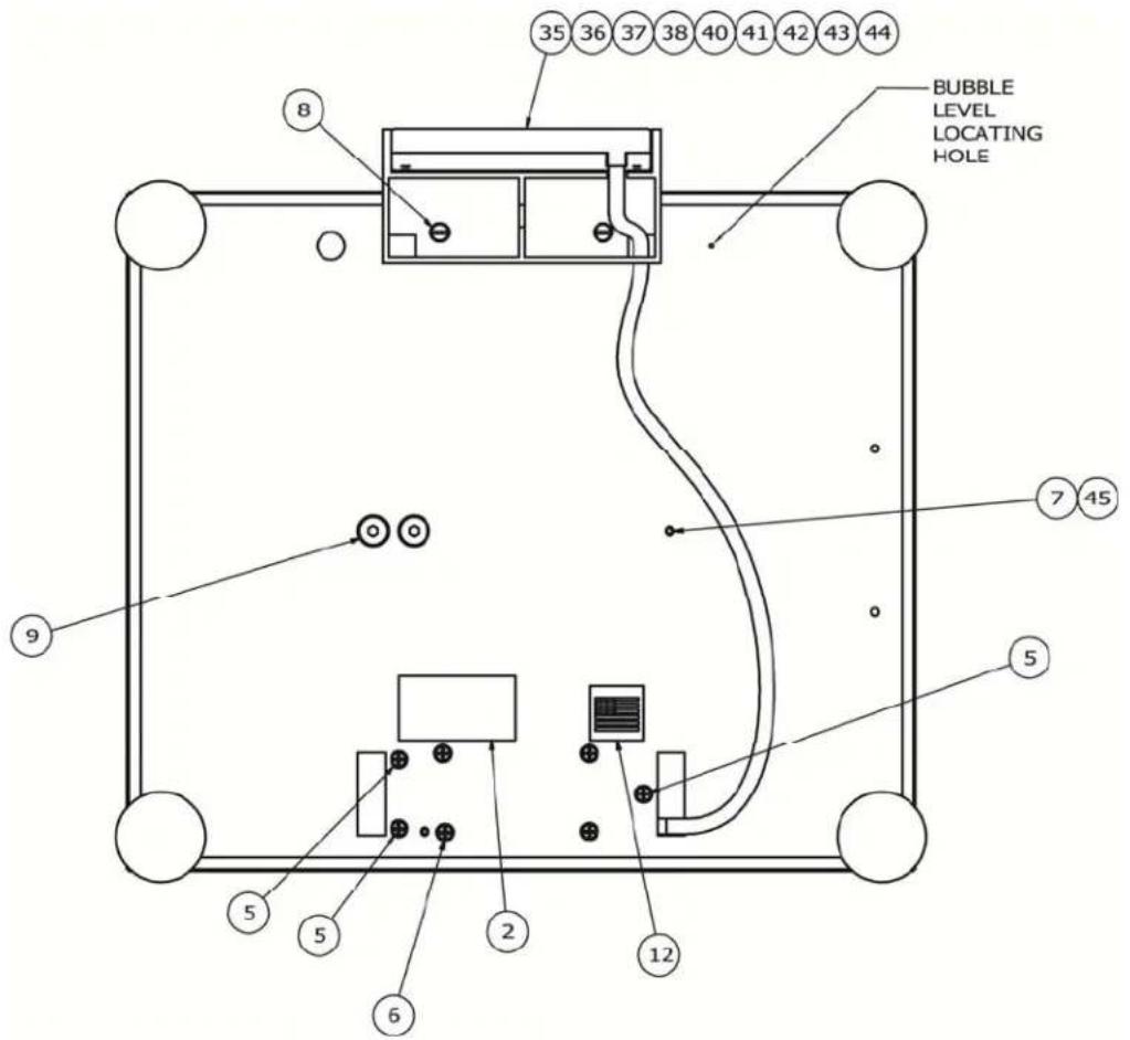
PARTS IDENTIFICATION, CONT.
(ALL MODEL EXCEPT APS250)

VIEW SHOWN WITHOUT COVER
(COMMODITY TRAY)
| ITEM | PART NO. | QTY | DESCRIPTION |
| 4 60 | 21-0623 4 SCW P | AN-HEAD.. MACHINE-SCW 06-32X.750 | |
| 7 60 | 21-1069 2 SCW C | UP-POINT. SET-SCREW.. 10-32X.25 NYLON PATCH | |
| 9 60 | 21-1706 4 SCW FL | LAT-HEAD. CAP-SCREW.. .25-20X.625 | |
| 13 66 | 80-0004 4 WASHER | LOCK INT TOOTH #6 TYPE A Z-PL | |
| 29 | 8527-C500-0A | 1 | ANALOG PCB |
| 45 | 593R1007 | 2 | FACTORY SET LABEL |
PARTS IDENTIFICATION, CONT.
(APS250 ONLY)

PARTS IDENTIFICATION, CONT.
(APS250 ONLY)
| ITEM | PART NO. | QTY | DESCRIPTION |
| 1 | 1960-B465-08 | 2 | SPACER FOR EB-XXX-XXXX |
| 3 | 6013-0077 | 4 | HEX NUT |
| 4 60 | 13-0295 4 NUT #1 | 10-32 H | EX Z/P |
| 8 60 | 21-0950 4 SCW | HEX-HEAD.. MACHINE-SCW 10-32X1.50 Z/P | |
| 10 60 | 21-1108 2 SCW | FILLISTER. MACHINE-SCW 10-32X.375 | |
| 12 65 | 40-1123 4 LEVEL | LER SCREW, 3/8-16 X 1 1/4", BLACK | |
| 13 65 | 60-1072 A/R ADHESIVE, LOCTITE 49 | ||
| 16 66 | 90-0001 1 BULLSEYE BUBBLE LEVEL | ||
| 17 85 | 27-0524-1A 1 LOAD CELL ASSY, 100KG | ||
| 18 85 | 27-0525-08 1 BASE PLATE, 250 | ||
| 19 | 8527-0526-08 | 1 | COVER, 18X18 |
| 20 | 8527-0534-08 | 1 | TOP PLATE, 250 |
| 22 | 8527-C505-08 | 1 | PCB COVER |
A/R = AS REQUIRED
PARTS IDENTIFICATION, CONT.
(APS250 ONLY)
| ITEM | PART NO. | QTY | DESCRIPTION |
| 2 59 | 3GR986 1 SERIAL | TAG ASSY | |
| 6 60 | 21-0625 3 SCW FL | AT-HEAD. MACHINE-SCW 06-32X.375 | |
| 7 60 | 21-0659 4 SCW FL | AT-HEAD. MACHINE-SCW 06-32X1.00 | |
| 9 60 | 21-1069 1 SCW C | UP-POINT. SET-SCREW.. 10-32X.25 NYLON PATCH | |
| 10 60 | 21-1108 2 SCW F | ILLISTER. MACHINE-SCW 10-32X.375 | |
| 11 60 | 21-1706 4 SCW FL | AT-HEAD. CAP-SCREW.. .25-20X.625 | |
| 14 66 | 50-0087 1 LABEL, | MADE IN USA (WITH FLAG) 1" X 1" | |
| 23 85 | 27-D510-7A 1 DISPLAY | SUB-ASSY, 250 |
PARTS IDENTIFICATION, CONT.
(APS250 ONLY)

VIEW SHOWN WITHOUT COVER
(COMMODITY TRAY)
| ITEM | PART NO. | QTY | DESCRIPTION |
| 5 60 | 13-0315 4 NUT #6 | -32 HEX | SMALL PATTERN Z/P |
| 11 60 | 21-1706 4 SCW FLAT-HEAD. CAP-SCREW.. .25-20X.625 | ||
| 15 66 | 80-0004 4 WASHER LOCK INT TOOTH #6 TYPE A Z-PL | ||
| 21 | 8527-C500-0A | 1 | ANALOG PCB |
PARTS IDENTIFICATION, CONT.
SCALE DISPLAY and APSRD (REMOTE DISPLAY)
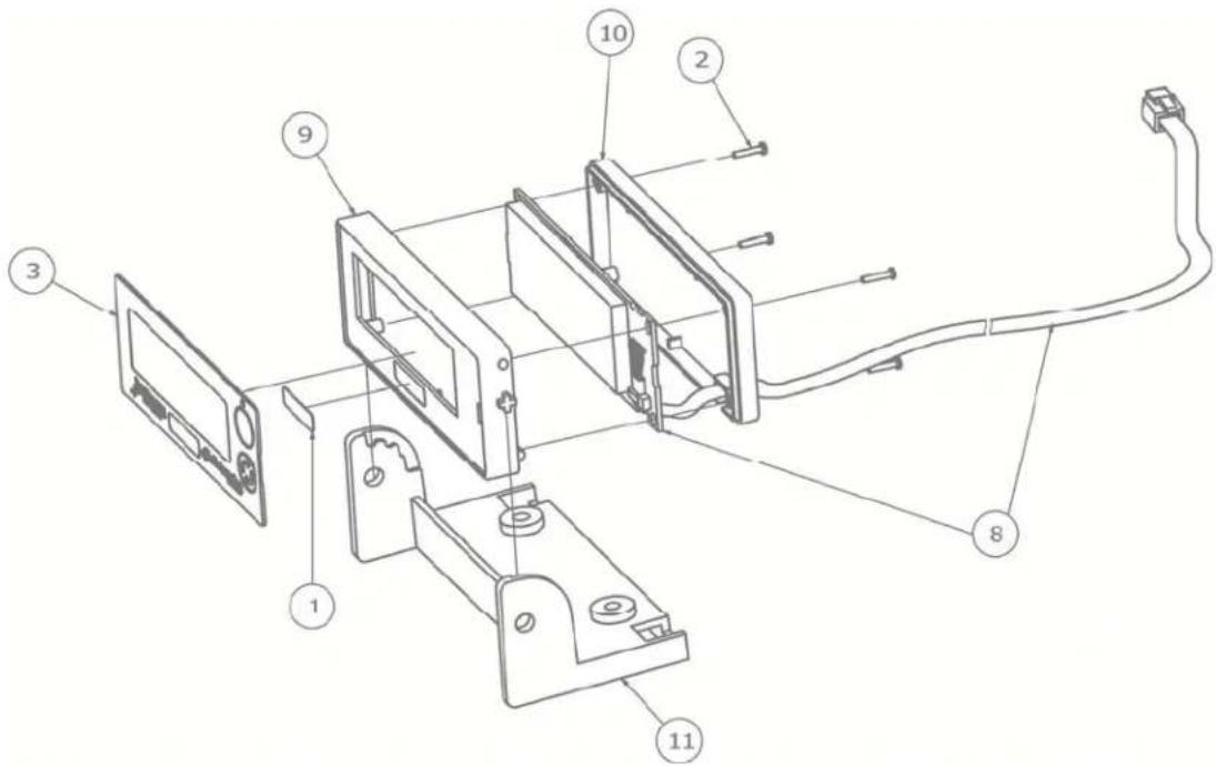
| ITEM | PART NO. | QTY | DESCRIPTION |
| 1 | 5930-0146-08 | 1 | CAPACITY LABEL |
| 2 60 | 21-2078 4 SCW P | AN-HEAD PHILLIPS #1-32X3/8" THD FORM, SS | |
| 3 | 8527-0515-08 | 1 | APS KEYPAD |
| 4 85 | 27-C502-0A 1 PCB ASSY | APS10 DISPLAY | |
| 5 85 | 27-C502-1A 1 PCB ASSY | APS15/160 DISPLAY | |
| 6 85 | 27-C502-2A 1 PCB ASSY | APS30/70/150 DISPLAY | |
| 7 85 | 27-C502-3A 1 PCB ASSY | APS250 DISPLAY | |
| 8 85 | 27-C502-4A 1 PCB ASSY | APSRD DISPLAY | |
| 9 | 8527-D506-08 | 1 | ENCLOSURE FRONT |
| 10 | 8527-D507-08 | 1 | ENCLOSURE BACK |
| 11 | 8527-D508-08 | 1 | ENCLOSURE MOUNT |
DISPLAY EXTENSION CABLE
| ITEM | PART NO. | QTY | DESCRIPTION |
| * | 6600-2007 1 | CABLE | 7FT APS DISPLAY EXTENSION |
* Not Shown
STATEMENT OF LIMITED WARRANTY
Detecto Scale warrants its equipment to be free from defects in material and workmanship as follows: Detecto warrants to the original purchaser only that it will repair or replace any part of equipment which is defective in material or workmanship for a period of two (2) years from date of shipment. Detecto shall be the sole judge of what constitutes a defect.
During the first ninety (90) days Detecto may choose to replace the product at no charge to the buyer upon inspection of the returned item.
After the first ninety (90) days, upon inspection of the returned item, Detecto will repair or replace it with a remanufactured product. The customer is responsible for paying for the freight both ways.
This warranty does not apply to peripheral equipment not manufactured by Detecto; this equipment will be covered by certain manufacturer's warranty only.
This warranty does not include replacement of expendable or consumable parts. This does not apply to any item which has deteriorated or damaged due to wear, accident, misuse, abuse, improper line voltage, overloading, theft, lightning, fire, water or acts of God, or due to extended storage or exposure while in purchaser's possession. This warranty does not apply to maintenance service. Purchased parts will have a ninety (90) day repair or replacement warranty only.
Detecto may require the product to be returned to the factory; item(s) must be properly packed and shipping charges prepaid. A return authorization number must be obtained for all returns and marked on the outside of all returned packages. Detecto accepts no responsibility for items lost or damaged in transit.
Conditions Which Void Limited Warranty
This warranty shall not apply to equipment which:
A.) Has been tampered with, defaced, mishandled or has had repairs and modifications not authorized by Detecto.
B.) Has had serial number altered, defaced, or removed.
C.) Has not been properly grounded according to Detecto's recommended procedure.
Freight Carrier Damage
Claims for equipment damaged in transit must be referred to the freight carrier in accordance with freight carrier regulations.
This warranty sets forth the extent of our liability for breach of any warranty or deficiency in connection with the sale or use of the product. Detecto will not be liable for consequential damages of any nature, including but not limited to, loss of profit, delays or expenses, whether based on tort or contract. Detecto reserves the right to incorporate improvements in material and design without notice and is not obligated to incorporate improvements in equipment previously manufactured.
The foregoing is in lieu of all other warranties, express or implied including any warranty that extends beyond the description of the product including any warranty of merchantability or fitness for a particular purpose. This warranty covers only those Detecto products installed in the forty-eight (48) contiguous continental United States.

- Setup and Operation Manual
- TABLE OF CONTENTS
- PRECAUTIONS
- INTRODUCTION
- FCC COMPLIANCE STATEMENT
- COPYRIGHT
- DISCLAIMER
- PROPER DISPOSAL
- Options
- Certifications
- SITE PREPARATION REQUIREMENTS
- Site Requirements
- Environmental Conditions
- SITE PREPARATION REQUIREMENTS, CONT.
- Electrical Power
- Electrical Noise Interference
- Transient Suppression
- RFI Immunity
- INSTALLATION
- (ALL MODELS EXCEPT APS250)
- Unpacking
- Level Adjustment
- INSTALLATION, CONT.
- (APS250 ONLY)
- Unpacking and Setup
- Unpacking and Setup, Cont.
- Interconnections
- Data Cable Installation
- SCALE DISPLAY/SERIAL PORT 1
- REMOTE DISPLAY/SERIAL PORT 2
- POS/SERIAL PORT 3
- USB Cable Installation
- USB
- Power Adapter
- 12VDC
- KEYPAD FUNCTIONS
- ANNUNCIATORS
- OZ
- lb
- kg
- (STABLE)
- →0←(ZERO)
- SETUP AND CONFIGURATION
- To Enter Setup
- TYPE (Scale Type)
- SETUP AND CONFIGURATION, CONT.
- Un5 (Motion Range)
- F ILtr (Adjustable Digital Filtering)
- CAL 16 (Calibration)
- PORT (RS-232 Serial Port 1)
- Port2 (RS-232 Serial Port 2)
- Port3 (POS Serial Port 3 - OPOS Compatible)
- USB (USB Port)
- H, rES (High Resolution Weight Mode)
- btd,5 (Button Disable)
- ERROR AND STATUS DISPLAYS
- Display
- Meaning
- CARE AND CLEANING
- SECURITY SEAL INSTALLATION
- APSRD (REMOTE DISPLAY)
- PARTS IDENTIFICATION, CONT.
- SCALE DISPLAY and APSRD (REMOTE DISPLAY)
- STATEMENT OF LIMITED WARRANTY
- Conditions Which Void Limited Warranty
- Freight Carrier Damage
Brand : Cardinal Detecto
Model : APS15
Category : Scale