
VVS-1 - Door/Window Sensor OPTEX - Free user manual and instructions
Find the device manual for free VVS-1 OPTEX in PDF.


| Product Type | Non-contact door/window sensor for automatic sliding doors |
| Brand | Optex |
| Model | VVS-1 |
| Cover Color | Black |
| Mounting Height | 2.2 to 4.2 m (7'3" to 13'10") |
| Detection Method | Image recognition (Vector focus method) |
| Power Supply | 24 VDC (dedicated power supply input: 85-264 VAC) |
| Power Consumption | < 5.5 W |
| Activation Output | Form A relay, 50 V, 0.1 A max (resistive load) |
| Output Hold Time | Approx. 0.5 sec |
| Operating Temperature | -10°C to 50°C (14°F to 122°F) |
| Operating Humidity | 30 to 85% (no condensation) |
| Operating Illuminance | 100 to 100,000 lx |
| Communication | Bluetooth 4.1 |
| LAN Specification | 10/100Base-T (X) |
| Recommended Browsers | Internet Explorer 11, Chrome 55 or later |
| Warm-up Time | Approx. 30 sec after power on |
| Weight | 560 g (20 oz) |
| Accessories | Cable 3 m, mounting template, manual set, mounting plate, fixing screws, protection seal set |
| Safety Output | Optocoupler (refer to header sensor manual) |
| Application | Header mount for automatic sliding doors |
Frequently Asked Questions - VVS-1 OPTEX
User questions about VVS-1 OPTEX
0 question about this device. Answer the ones you know or ask your own.
Ask a new question about this device
Download the instructions for your Door/Window Sensor in PDF format for free! Find your manual VVS-1 - OPTEX and take your electronic device back in hand. On this page are published all the documents necessary for the use of your device. VVS-1 by OPTEX.
USER MANUAL VVS-1 OPTEX
Operation manual VVS-1
5927191 2018.05
Manufacturer's statement
■ This product is a non-contact switch intended for header mount for use on an automatic sliding door. Do not use for any other applications.
■ Be sure to install and adjust the sensor in accordance with the local laws and standards of the country in which the product is installed.
■ The image taken by this product is only used for detecting the entry direction and speed of humans entering into the door. There is no personally identifiable information. Furthermore, the image is immediately deleted.
■ Be sure to use this product in a state of mounting the header sensor (OA-PRESENCE TN/OA-AXIS T/OAM-DUAL series/X-ZONE series *).
* Contact our local sales representative in case of installing this product with OA-AXIS T, OAM-DUAL series and X-ZONE series.
Read this operation manual carefully before use to ensure proper operation of this product. Failure to read this operation manual may cause improper operation and may result in serious injury or death of a person. The meanings of the symbols are as follows.
WARNING
Disregard of the warning symbol can cause improper operation which may cause death or serious injury.
CAUTION
Disregard of the caution symbol can cause improper operation which may cause injury of a person or damage the object.
WARNING
Danger of fire and electric shock
■ Do not wash, disassemble, rebuild or repair the product, otherwise it may cause electric shock or breakdown of the equipment.
WARNING
Danger of getting caught in the door
■ Correctly install and set up the sensor within the range of specification.
This product detects the entry direction and speed of humans entering into the door by means of image processing. After recognizing the movement, the sensor judges if and when the activation output should be sent to the door.
■ Detection method of VVS-1
■ Environment in the vicinity of the door.
- Do not place the equipment generates strong radio waves and noises in the vicinity of the door.
■ The following conditions are not suitable for stable operations.
- When the floor in the human recognition area suddenly changes. (e.g. due to spaying water on the floor)
- When there are moving objects (e.g. foliage plants) in the human recognition area.
- When water drops and stain stick to the lens.
■ The following conditions are not suitable for detecting humans.
- When the human recognition area is extremely dark.
- When the strong reflection light directly goes into the product.
- When the difference of the floor and clothing color is vague.
EU declaration of conformity
Hereby, OPTEX declares that the radio equipment type VVS series are in compliance with RED 2014/53/EU.
The full text of the EU DoC is available at the following internet address; www.optex.net
FCC WARNING (For USA)
This device complies with part 15 of the FCC Rules. Operation is subject to the following two conditions:
(1) This device may not cause harmful interference, and
(2) this device must accept any interference received, including interference that may cause undesired operation.
Note: This equipment has been tested and found to comply with the limits for a Class A digital device, pursuant to part 15 of the FCC Rules. These limits are designed to provide reasonable protection against harmful interference when the equipment is operated in a commercial environment. This equipment generates, uses, and can radiate radio frequency energy and, if not installed and used in accordance with the instruction manual, may cause harmful interference to radio communications. Operation of this equipment in a residential area is likely to cause harmful interference in which case the user will be required to correct the interference at his own expense.
Inform building owner / operator of the following items
WARNING Danger of fire and electric shock
■ Always keep the camera lens clean. If dirty, wipe the camera lens with a damp cloth. Do not use any cleaner / solvent.
■ Do not wash the product with water.
■ Do not disassemble, rebuild or repair yourself, otherwise an electric shock may occur.
■ When the operation indicator blinks green, contact your installer or service engineer.
■ Always contact your installer or service engineer when changing the settings.
■ Do not paint the product.
- Notice -
■ When turning the power ON, always walk-test the detection area to ensure the proper operation.
■ Do not place any objects that move or emit light in the detection area.
(e.g. plant, illumination, etc.)
Specifications
| Model | VVS-1 |
| Cover color | Black |
| Mounting height | 2.2 to 4.2m (7"3" to 13'10") (Maximum height depends on the header sensor) |
| Image recognition area | See Image recognition area |
| Detection method | Image recognition (Vector focus method) |
| Power supply | 24VDC (Dedicated power supply Rating input : 85 to 264VAC 1 Output voltage: 24VDC) |
| Power consumption | < 5.5W |
| Output | Activation output : Form A relay 50V 0.1A Max. (Resistance load)Safety output : See Operation manual of the header sensor |
| Operation indicator | See Adjustments, Checking |
| Output hold time | Approx. 0.5sec. |
| Operating temperature | -10°C to 50°C (14°F to 122°F) |
| Operating humidity | 30 to 85% (No condensation) |
| Operating illuminance | 100 to 100,000 lx |
| LAN specification | 10/100Base -T (X) |
| Communication method | Bluetooth 4.1 |
| Browser | Internet Explorer 11, Chrome 55 or later recommended |
| Warm-up | Approx. 30sec. from turning ON the power supply |
| Weight | 560g (20oz) |
| Accessories | 1 Cable 3m (9'11"), 1 Mounting template , 1 manual set (Operation manual, Web setting manual and App User guide), 1 Mounting plate , 2 Mounting plate fixing screws, 1 Header sensor fixing screw (Attached to the main body), 1 Protection seal set |
*The specifications herein are subject to change without prior notice due to improvements.
Outer dimensions and part names

[mm (inch)]
(1) Power/output connector
(7) IP address reset switch
(2) App's password reset switch
(8) LAN port
(3) Header sensor mounting hole
(9) Dipswitches
(4) Header sensor connector
(10) Screw pocket
(5) Removing pawl
(11) Operation indicator
(6) IP address reset indicator
(12) Camera
Image recognition area

[Human recognition area]
The setting upper limit value for human recognition area
(Left side / Right side / Depth) is up to 10m (32'10"). Please set according to the setting environment.
For details, refer to Web setting manual.
[eTracker area]
For details, refer to Web setting manual.
[Header sensor area]
For details, refer to Operation manual for the header sensor.
[Door position]
For details, refer to Web setting manual.
Installation

WARNING
Danger of fire and electric shock
■ When passing the cable through the hole, do not tear the shield otherwise it may cause electric shock or breakdown of the sensor.

WARNING
Danger of getting caught in the door
- Do not use exceeding the mounting height of the specification. - Do not mount on the oblique surface.
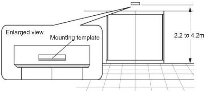
STEP 1 Affix the mounting template at the desired mounting position. * Mounting height depends on the header sensor.
STEP 2 Drill two mounting holes of ∅3.4mm (∅1/8").
STEP 3 To pass the cable through the header, drill a wiring hole of ø12mm (ø1/2").
STEP 4 Remove the mounting template.
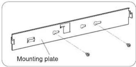
STEP 5 Fasten the screws aligning the mounting plate to the mounting holes.
2

natural_image
Diagram of a mechanical component with directional arrows indicating movement or force (no text or symbols)STEP 6 Wiring the cable to the door controller.

WARNING
Danger of fire and electric shock
■ Before starting the procedure, make sure that the power is turned OFF.
■ Do not use this product exceeding the power supply range.
■ When passing the cable through the hole, do not tear the shield.
Otherwise it may cause electric shock or breakdown of the sensor.
■ Do not extend, forcibly bend, pull off, twist, and bundle the cable.
Door controller side

natural_image
Pure electrical circuit lines without any symbols- White
- Brown
- Green
- Yellow
- Pink (+)
- Blue (-)
- Red (+)
- Black (-)
Power supply
○ ○
24VDC
Activation
→
Form A relay
output
50V 0.1A max.
Safety output
1
Opto coupler
Safety input
○—冲
Opto coupler
STEP 7 Remove the housing cover.
Raise the knob on the left side of the housing cover while holding the main body.

natural_image
Line drawing of hands installing or adjusting a device component, showing arrows indicating assembly or adjustment (no text or symbols)STEP 8 Fix the header sensor to main body by a screw, and connect to the header sensor connector.


natural_image
Technical line drawing of a mechanical component or housing assembly (no text or symbols visible)* Contact our local sales representative in case of installing this product with OA-AXIS T, OAM-DUAL series and X-ZONE series.
Installation
STEP 9 Fix the main body to the mounting plate.
Put the main body on the hook of the mounting plate.
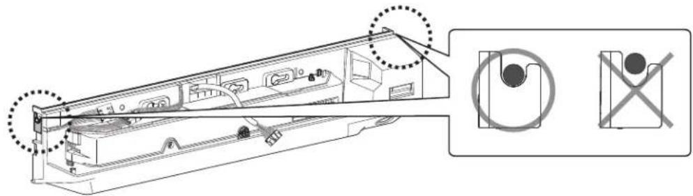
Perform fitting and pull down while pressing the main body to the mounting plate.


natural_image
Illustration of hands holding a device with a downward arrow indicating compression or disassembly (no text or symbols present)Confirm that the protruded parts of this product are fully lowered and fixed on the both sides of claws of the mounting plate.
natural_image
Technical line drawing of a mechanical assembly with no visible text or symbolsSTEP 10 Connect the wiring connector and the power/output connector.

WARNING
Danger of fire and electric shock
■ Make sure that the connectors are properly connected.

natural_image
Technical line drawing of a mechanical assembly with internal components (no text or symbols)When detaching this product from the mounting plate, raise the sensor upward while pushing down the removing pawl as shown below.

STEP 11 Supply power to the sensor. After warm-up for approx. 30sec., this product becomes the stand-by state.

Adjust the image recognition area and set the dipswitches.
(Refer to Web setting manual.)
For the header sensor, refer to the operation manual of the header sensor.

For the dust proof, affix the attached protection seals to
the openings section of this product.

Installation
STEP 14
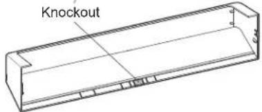
Place the housing cover.
* Check that the housing cover and wiring are not interfering.
If wiring is to be exposed, break the knockout.

WARNING
Danger of fire and electric shock
■ Do not use without the housing cover.
■ When using the cable knockout, install on the indoors or use the rain cover (separately available) otherwise electric shock or breakdown of the sensor may occur.
Main body

natural_image
Technical line drawing of a device casing with internal components and mounting holes (no text or symbols)Housing cover
Adjustments
App password reset switch
Use this switch when resetting the app's password to the default values (0000). Push the switch for 2 seconds after confirming that the product is in the stand-by status. (See [Operation indicator])
IP address reset switch
Use this switch when resetting the IP address to the default values (192.168.0.249). Push the switch for 2 seconds after confirming that the product is in the stand-by status. When the reset is confirmed, the IP address reset indicator goes on from the blinking status.
LAN port
Perform the Web setting through LAN connection. For the setting method, see the attached Web setting manual.

Operation indicator
| Warm-up Stand-by Detection | Cross traffic cancel | During connecting to the app | App password reset | ||
| Green glimmering | Green Red | Blue glimmering | Slow green & blue blinking | Fast green & blue blinking * | |
* Operation indicator is turned off after completing.
| Sensor failure |
| Fast green blinking |
The operation status of the header sensor is displayed on the operation indicator of the header sensor. For details, refer to the operation manual of the header sensor.
Smart device app
This product links with the smart device app "VVS eTracker", and the app can show the contribution ratio to the environment compared to conventional sensors. For details, refer to VVS eTracker User guide.
Dipswitch settings
Dipswitch 1 : Warm-up output
The Activation output during warming up (approx. 30sec.) when just after turning on the power and changing the web setting is adjustable. When setting to "OFF", the door becomes the closed state, and when setting to "ON", the door becomes the opened state. Normally, set to "ON".
OFF

1
ON

1
Dipswitch 3 : Activation output
Dipswitch 3 is for the Activation output to the door controller.
N.O.

3
N.C.

3
*Dipswitch 2, 4 to 8 is not used.
Checking
Check the operation in the operation mode according to the chart below.
| Entry | Power OFF | Warm-up (Approx. 30sec.) | Stand-by | Cross traffic cancel | Detection | Detection (The header sensor) | |
| (Image) |  | 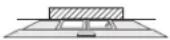 | 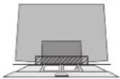 |  | 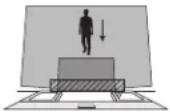 |  | |
| Operation indicator | None | Green glimmering | Green | Blue glimmering | Red | *1 | |
| Activation output | N.O. | /← | —*2 | /← | /← | — | — |
| N.C. | /← | /←*2 | — | — | /← | — | |
| Safety output | *1 | — | *1 | — | — | *1 | |
*1 See the operation manual of the header sensor. *2 When the setting of dipswitch 1 is "ON"
Troubleshooting
| Symptoms | Possible cause | Possible countermeasures | Reference |
| Door does not open when a person enters the detection area. | Wrong power supply voltage. | Set to the stated voltage. | Specifications |
| Wrong wiring or connection failure. | Check the wires and connector. | Installation: STEP 6,8,10 | |
| Smears of camera lens. | Remove the stains of the camera lens. | Inform building owner / operator of the following items | |
| Sensitivity is too low. | Set the sensitivity higher. | Web setting manual | |
| Human recognition area is narrow. | Check the human recognition area. | Web setting manual | |
| Ambient illuminance is too low. | Either raise the detection sensitivity or raise the illuminance of the installation environment. | Specifications, Web setting manual | |
| Door opens when no one is in the detection area. (Ghosting) | There are some moving objects/shades within the area of the human recognition area. | Either adjust the human recognition area or move the detection object outside of the area. Or check the Immunity. | Manufacturer's statement, Web setting manual |
| Water drops are adhering to the camera lens. | Use the rain-cover. (Separately available) Or wipe the camera lens with a damp cloth. Or install in a place keeping the water drops off. | Manufacturer's statement | |
| Sensitivity is too high. | Set the sensitivity lower. | Web setting manual | |
| The setting of the header sensor is not appropriate. | Check the operation manual of the header sensor. | Operation manual of the header sensor | |
| The human recognition area is crossing on the door. | Check the door position. | Web setting manual | |
| Door remains open. | The setting of the header sensor is not appropriate. | Check the operation manual of the header sensor. | Operation manual of the header sensor |
| Operation indicator is blinking green. | Sensor failure. | Contact your installer or service engineer. | Adjustments "Operation indicator" |
| Cannot connect to the web setting. | Setting of IP address is not appropriate. | Check this product and the IP address of the PC. | Web setting manual |
| Wrong wiring LAN cables. | Check LAN cables. | Web setting manual | |
| Is connecting at warm-up. | After checking the stand-by status, connect it. | Adjustments "Operation indicator" | |
| The types of LAN cables are different. | Use the LAN cables suitable for the product specification. | Specifications | |
| Cannot connect to the app. | Turn OFF Bluetooth of the smart device. | Turn ON Bluetooth of the smart device. | VVS eTracker User guide |
| Radio waves of Bluetooth have not reached. | Approach to the product. | VVS eTracker User guide | |
| Is being connected from other smart device. | Check the operation indicator. | Adjustments "Operation indicator" | |
| The cross traffic cancel does not work. | The setting of the door position is not appropriate. | Check the door position. | Web setting manual |
| The detection area setting of the header sensor is too wide. | Check the detection area of the header sensor. | Operation manual for the header sensor | |
| Reaction is too slow, or too fast. | The setting of the Activation output timing is not appropriate. | Check the Activation output timing. | Web setting manual |
| Not become to stand-by status. | Warm-up has not completed due to the setting error. | Turn the power OFF and ON again. | Web setting manual |
Contact your installer or the sales engineer if:
- You need to change the settings or replace the sensor.
- The trouble still persists after checking and remedying as described above.
* The Bluetooth® word mark and logos are registered trademarks owned by the Bluetooth SIG, Inc. and any use of such marks by OPTEX CO., LTD. is under license.
Manufacturer
OPTEX CO., LTD.
5-8-12 Ogoto Otsu 520-0101, Japan
North and South America Subsidiary
OPTEX INCORPORATED
18730 S. Wilmington Avenue, Suite 100 Rancho
Dominguez CA 90220 U.S.A
TEL.: +1-800-877-6656 FAX.: +1(310)898-1098
WEBSITE: www.ot-inc.com
European Subsidiary
OPTEX Technologies B.V.
Henricuskade 17, 2497 NB The Hague, The Netherlands
TEL.: +31(0)70 419 41 00 FAX.: +31(0)70 317 73 21
E-MAIL: info@optex.eu WEBSITE: www.optex.eu
East coast office
8510 McAlpines Park Drive, Suite 108
Charlotte, NC 28211 U.S.A.
TEL.: +1-800-877-6656 FAX.: +1(704)365-0818
WEBSITE: www.ot-inc.com
Web setting manual VVS-1
5927191 2018.05
Introduction Setting items
Complete the steps up to [Operation manual : Installation - STEP 11]
before performing the setting of the following.
End all applications under starting up on the PC before starting the setting.
The Web setting screen is divided into the user's and the administrator's screen. When changing the setting of this product, log in as an administrator. Implement the change of setting by skilled installer in order to secure safety.
| User Function available Password in factory default setting | ||
| General user | Status display, camera image monitoring | user |
| Administrator | Status display, camera image monitoring, area setting, LAN connection setting, Password setting | admin |
Access to the web setting
STEP 1
After the user confirmed that this product is in stand-by condition (Operation indicator is green), connect the PC and this product with LAN cables.

natural_image
Technical line drawing of a mechanical device with internal components and mounting points (no text or symbols)LAN portOperating indicator
STEP 2
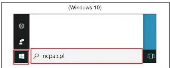
Start up the PC, click the start button at the bottom left of the screen, enter "ncpa.cpl" in the search bar and execute it.

STEP 3
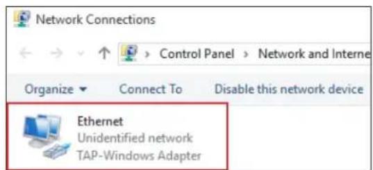
Right-click [Local Area Connection] to which this product is connected, and select [Properties].
STEP 4
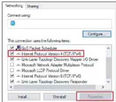
Select [Internet Protocol Version 4 (TCP/IPv4)] to click the [Property] button.
STEP 5
Enter a check mark to [Use the following IP address], and set up the IP address (Example [192.168.0.100]) other than the IP address of this product ([192.168.0.249] at factory default) and subnet mask (Example [255.255.255.0]). Provide a blank in the other items.

After inputting, click the [OK] button.
STEP 6
Start up the web browser, and input the IP address ([192.168.0.249] at factory default) of this product into the address input column.

STEP 7
The logon screen is displayed.

* After the setting is completed, return the PC to an appropriate setting if needed.
* As for the other OSs, check it to our company sales person in charge.
Area settings
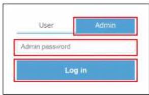
STEP 1 Click [Admin] on the login screen and enter the password (default setting: admin). After entering the password, click [Login].
flowchart
graph TD
    A["User"] --> B["Admin"]
    B --> C["Admin password"]
    C --> D["Log In"]
STEP 2 Click [Area] from the upper menu.

STEP 3 Set the following each item and press the application button below.
![Door position Drag and drop the 1 and the 2 marks on the camera image to specify the door opening width. Installation height Set the height of the sensor installation suited to the installation environment. Sensitivity Adjust the detection sensitivity fitting for the installation environment. Normally, set to [Standard]. Human body detection size Adjust the human body detection size suited to the installation environment. Normally, set to [Standard]. Immunity Unnecessary openings due to following conditions may be reduced by selecting an object(s). In normal cases it can be disabled. Area settings Door Position ⑦ eTracker area ⑦ Installation height ① 2490 mm (56 inch) Human recognition area ② 3000 mm (118.1 inch) (Left side) 3000 mm (118.1 inch) (Right side) 6000 mm (236.2 inch) (Depth) Other settings Activation output timing ⑦ Slow Fast (3500 msec) Sensitivity ⑦ Standard Human body detection size ⑦ Standard Immunity ⑦ Shopping cart Shadows (sunlight) Shadows (light source other than sunlight) Activation output timing Adjust the Activation output timing fitting for the installation environment. Specifying a "Fast" value speeds up the Activation output timing, ensuring safety for rushing in, while energy-saving efficiency gets worse as Activation output is made earlier for a slow approach. Specifying a "Slow" value speeds down the Activation output timing, ensuring higher energy-saving efficiency, while safety for a quick approach such as rushing in gets worse. eTracker area Drag and drop the 3 and the 4 marks on the camera image to specify the detection area range configured (or to be configured) for the existing automatic door sensor. * eTracker is a unique indicator that shows the contribution rate to the environment compared with the conventional automatic door sensor, and it can numerically indicate the effect of the installation of this device. To view eTracker, install the application dedicated to smart devices, "VVS eTracker", on your device. Human recognition area Adjust the human recognition area suited to the installation environment. In normal case, specify the setting so that the area should cover the entire camera image. On the image, the yellow line is displayed. *When the cursor is moved over to ⑦ on the Web screen, the explanation is shown.](/content/2026/05/1128150/images/5201a22122e8d495b890cc993441323435a36cd7bf164fcf1eb710933e8881c1.jpg)
*As for other setting items and the detailed setting method, confirm the explanation on the web screen.
Password settings

* Windows is a registered trademarks of Microsoft Corporation in the United States and/or other countries.
Manufacturer
OPTEX CO., LTD.
5-8-12 Ogoto Otsu 520-0101, Japan
North and South America Subsidiary
OPTEX INCORPORATED
18730 S. Wilmington Avenue, Suite 100 Rancho
Dominguez CA 90220 U.S.A
TEL.: +1-800-877-6656 FAX.: +1(310)898-1098
WEBSITE: www.ot-inc.com
European Subsidiary
OPTEX Technologies B.V.
Henricuskade 17, 2497 NB The Hague, The Netherlands
TEL.: +31(0)70 419 41 00 FAX.: +31(0)70 317 73 21
E-MAIL: info@optex.eu WEBSITE: www.optex.eu
East coast office
8510 McAlpines Park Drive, Suite 108
Charlotte, NC 28211 U.S.A
TEL.: +1-800-877-6656 FAX.: +1(704)365-0818
WEBSITE: www.ot-inc.com
- Operation manual VVS-1
- Manufacturer's statement
- WARNING
- CAUTION
- Danger of fire and electric shock
- Danger of getting caught in the door
- EU declaration of conformity
- FCC WARNING (For USA)
- Inform building owner / operator of the following items
- WARNING Danger of fire and electric shock
- - Notice -
- Installation
- STEP 9 Fix the main body to the mounting plate.
- STEP 10 Connect the wiring connector and the power/output connector.
- STEP 11 Supply power to the sensor. After warm-up for approx. 30sec., this product becomes the stand-by state.
- STEP 14
- Adjustments
- App password reset switch
- IP address reset switch
- LAN port
- Operation indicator
- Smart device app
- Dipswitch settings
- Dipswitch 1 : Warm-up output
- Dipswitch 3 : Activation output
- Checking
- OPTEX CO., LTD.
- OPTEX INCORPORATED
- OPTEX Technologies B.V.
- East coast office
- Web setting manual VVS-1
- Introduction Setting items
- Access to the web setting
- STEP 1
- STEP 2
- STEP 3
- STEP 4
- STEP 5
- STEP 6
- STEP 7
- Area settings
- Password settings
Brand : OPTEX
Model : VVS-1
Category : Door/Window Sensor