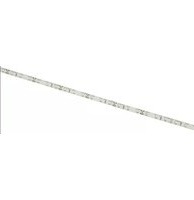
DIY-A60 - LED Lighting LYYT - Free user manual and instructions
Find the device manual for free DIY-A60 LYYT in PDF.


| Product Type | DIY Electronic Kit / Multimeter |
| Brand | LYYT |
| Model | DIY-A60 |
| Color | Black/Yellow |
| Dimensions | 150 x 80 x 30 mm |
| Weight | 200 g |
| Power Supply | 9V Battery (6F22) |
| Display | LCD, 3 1/2 digits (2000 counts) |
| DC Voltage Range | 200mV - 600V |
| AC Voltage Range | 200mV - 600V |
| DC Current Range | 200µA - 10A |
| Resistance Range | 200Ω - 2MΩ |
| Other Functions | Diode test, continuity buzzer, transistor test |
| Accuracy | ±0.5% (DCV), ±1.0% (ACV) |
| Safety Rating | CAT I 600V, CAT II 300V |
| Operating Temperature | 0°C to 40°C |
| Storage Temperature | -10°C to 50°C |
| Accessories Included | Test leads, battery, manual |
| Maintenance | Clean with dry cloth; do not use solvents |
| Spare Parts | Test leads (model TL-A60), 9V battery |
| Warranty | 1 year limited |
| Certifications | CE, RoHS |
Frequently Asked Questions - DIY-A60 LYYT
User questions about DIY-A60 LYYT
0 question about this device. Answer the ones you know or ask your own.
Ask a new question about this device
Download the instructions for your LED Lighting in PDF format for free! Find your manual DIY-A60 - LYYT and take your electronic device back in hand. On this page are published all the documents necessary for the use of your device. DIY-A60 by LYYT.
USER MANUAL DIY-A60 LYYT
natural_image
Electronic components including a black cable, wire coil, and earplifier (no text or symbols visible)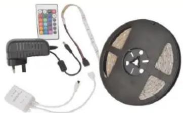
natural_image
Product photo of a film reel with attached control panel and power adapter (no visible text or symbols)DIY LED TAPE KIT
User Manual
DIY LED TAPE KIT - SINGLE COLOUR
Introduction:
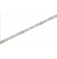
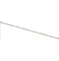
Thank you for purchasing the Lyyt DIY LED Tape Kit. LED tape is ideal for use on the underside of a counter tops, shelves, cupboards, around window frames or in an alcove of a ceiling to name just a few examples.
Before starting please ensure that you have read this instruction leaflet carefully. If you are unsure about any of the installation details, please have this installed by a competent installer.
Blister Contents:
1 x Reel of LED tape
1 x UK power adaptor
Possible Required tools: Scissors, Craft knife, Soldering iron and solder, 2 core DC wire and heat shrink tube.
Step 1: Preparation
Ensure that the surface you are attaching to is clear of dust and dirt. Clean thoroughly and leave to dry before fitting the tape.
Unravel the tape and connect the power supply. Check that all the LEDs are functioning correctly and if there are any faults return to your retailer without delay.
Step 2: Cutting
WARNING: Disconnect from the power supply before attempting any cutting.
Measure out each section and cut with sharp scissors at the marked 5cm intervals to achieve the perfect length. Do not discard any excess tape as it can be easily reconnected and used again (see FIG 2).
Step 3: Fitting:
Example 1: Simple straight run.
Clear the area you wish to install the tape and remove the backing paper, exposing the adhesive tape. Push tape firmly onto the surface. It is recommended to work on 50cm sections at a time in order to ensure a professional finish. When you reach the end of your installation cut at the marked cutting point.
Example 2: Requires cutting:
The tape can be cut at highlighted 5cm intervals for a perfect fit.
FIG 1:

You may also reconnect the two pieces by soldering the connection points together (FIG 2). The tape has two tracks for the DC voltage with + positive pole at the top and - negative pole at the bottom.
To reattach, use a craft knife to cut the Epoxy coating from the terminals.
Use a soldering iron and solder to connect the DC wire to the relative terminals be sure not to cause a short circuit when making these connections, as this will result in malfunction and possible damage to the power supply.
FIG 2:

WARNING: Only cut the tape on the highlighted intervals. Cutting the tape in other parts without due care will permanently damage that section of the tape and will result in malfunction.
Points to remember when using this tape
1) Only use the supplied power adaptor for the length of tape in the kit
2) Only cut the tape at the highlighted 5cm intervals.
3) Do not connect another reel and operate from a single power supply as this will seriously affect the performance.
3) The top track of the tape is the + Positive pole.
4) The bottom track of the tape is the - negative pole.
5) Ensure you connect the correct wires otherwise the tape will not work.
6) Ensure that when soldering there are no short circuits
7) We recommend use of heat shrink tubing to protect the connection.
8) Check that everything operates correctly before installing.
FAQ:
Q) Can I connect different colours in a chain?
A) Yes all the LEDs draw the same power, current and have the same connection but do not exceed the full reel length.
Q) Can you cut a reel of tape into many different sections then connect them all together?
A) Yes as long as you cut the tape at 5cm intervals highlighted.
Q) I have connected two reels together off one power supply and the LEDs are dim towards the end.
A) The power adaptor is only designed to operate the reel in the kit. Anything longer will seriously affect the performance.
Q) Can I connect the tape together to form a loop?
A) Yes you can. This will even the brightness out on the LEDS across the reel length
Q) Can I use the tape outdoors?
A) Yes, the tape is IP65 rated. Ensure that the terminated ends are heat shrink protected.
Q) Can I clean the tape?
A) Yes, the tape is IP65 rated and has an epoxy coating. Just wipe down with a damp cloth regularly to ensure continuing brightness
Q) Can I replace / patch damaged tape with a new piece
A) Yes, just highlight the effected area by the 5cm intervals. Cut out the faulty section then fit in a new piece soldering the connections securely and using heat shrink to protect the repaired connection.
Specifications
| Voltage | 12Vdc |
| Current consumption | 340mA/m |
| Power consumption | 4.08W/m |
| Number of LEDs | 60/m |
| LED Spacing | 16mm |
| Cut intervals | 5cm |
| Beam angle | 140° - 160° |
| LED type | SMD3528 or SMD2835 |
| IP rating | IP65 |
LED DIY TAPE KIT - RGB MULTI COLOUR
Introduction:
Thank you for purchasing the Lyyt DIY RGB LED Tape. LED tape is ideal for use on the underside of a counter tops, shelves, cupboards, around window frames or in an alcove of a ceiling to name just a few examples.
Before starting please ensure that you have read this instruction leaflet carefully. If you are unsure about anything please have the tape installed by a competent installer.
Contents:
1 x Reel of RGB LED tape
1 x UK power adaptor
1 x Control Box with IR remote handset
Possible required tools: Scissors, Craft knife, Soldering iron and solder, 4 core DC wire and heat shrink tube.
Step 1: Preparation
Ensure the surface you are attaching to is clear of dust and dirt. Clean thoroughly and leave to dry before fitting the tape.
Step 2: Connecting IR Controller:
Connect the 4pin connector to the control box and then to the LED tape (FIG 1). Plug in the power supply and use the IR remote control to select the various functions (Fig 2).
Unravel the tape to check that all the LEDs are functioning correctly. If there are any faults return to your retailer without delay.
FIG 1:

flowchart
graph LR
    A["Power IN"] --> B["Control Box"]
    B --> C["IR Receiver"]
    B --> D["Connector"]
    D --> E["LED Tape"]
    style A fill:#f9f,stroke:#333
    style B fill:#ccf,stroke:#333
    style C fill:#cfc,stroke:#333
    style D fill:#fcc,stroke:#333
    style E fill:#cff,stroke:#333
FIG 2:
| Brightness Rise (+) | Brightness Drop (-) | Off | On |
| Static Red | Static Green | Static Blue | Static White |
| Static Orange | Static Light Green | Static Deep Blue | 7 Colour changing program |
| Static Deep Yellow | Static Cyan | Static Brown | Gradually changing |
| Static Yellow | Static Light Blue | Static Pink | 7 Colour fade changing |
| Static Light Yellow | Static Sky Blue | Static Purple | 3 Colour quick changing |
Step 2: Cutting
WARNING: Disconnect from the power supply before attempting any cutting.
Measure out each section and cut with sharp scissors only at the marked 10cm intervals. Do not discard any excess tape as it can be easily reconnected and used again (see FIG 4).
Step 4: Fitting:
Clear the area you wish to install and remove the backing paper, exposing the adhesive tape. Push tape firmly onto the surface. It is recommended to work on 50cm sections at a time in order to ensure a professional finish. When you reach the end of your installation cut at the marked cutting point.
The tape can be terminated at highlighted 10cm cut intervals if less than a full reel is required.
FIG 3:

You may also reconnect the two pieces by soldering the point connections together. The tape has 4 tracks for the DC voltage:
Common (indicated as "+12V" on the tape), Green, Red and Blue
To re-attached use a craft knife to cut the Epoxy coating from the terminals.
Use a soldering iron and solder to connect the DC wire to the relative terminals be sure not to cause a short circuit in the process as it will not work.
FIG4:

flowchart
graph LR
    subgraph Left_Circuit
        A1["Cutting point"] --> B1["Cutting point"]
        B1 --> C1["Cutting point"]
        C1 --> D1["Cutting point"]
        D1 --> E1["Cutting point"]
        E1 --> F1["Cutting point"]
        F1 --> G1["Cutting point"]
        G1 --> H1["Cutting point"]
        H1 --> I1["Cutting point"]
        I1 --> J1["Cutting point"]
        J1 --> K1["Cutting point"]
        K1 --> L1["Cutting point"]
        L1 --> M1["Cutting point"]
        M1 --> N1["Cutting point"]
        N1 --> O1["Cutting point"]
        O1 --> P1["Cutting point"]
        P1 --> Q1["Cutting point"]
        Q1 --> R1["Cutting point"]
        R1 --> S1["Cutting point"]
        S1 --> T1["Cutting point"]
        T1 --> U1["Cutting point"]
        U1 --> V1["Cutting point"]
        V1 --> W1["Cutting point"]
        W1 --> X1["Cutting point"]
        X1 --> Y1["Cutting point"]
        Y1 --> Z1["Cutting point"]
        Z1 --> AA1["Cutting point"]
        AA1 --> AB1["Cutting point"]
        AB1 --> AC1["Cutting point"]
        AC1 --> AD1["Cutting point"]
        AD1 --> AE1["Cutting point"]
        AE1 --> AF1["Cutting point"]
        AF1 --> AG1["Cutting point"]
        AG1 --> AH1["Cutting point"]
        AH1 --> AI1["Cutting point"]
        AI1 --> AJ1["Cutting point"]
        AJ1 --> AK1["Cutting point"]
        AK1 --> AL1["Cutting point"]
        AL1 --> AM1["Cutting point"]
        AM1 --> AN["Required distance"]
    end
WARNING: Only cut the tape on the highlighted intervals. Cutting the tape in other parts without due care will permanently damage that section of the tape and will result in malfunction.
Points to remember when using this tape
1) Only cut the tape at the highlighted 10cm intervals.
2) Do not connect another reel and operate from a single power supply as this will seriously affect the performance.
3) Ensure you connect the correct wires otherwise the tape will not work.
4) Ensure that when soldering there are no short circuits
5) We recommend use of heat shrink tubing to protect the connection.
6) Check that everything operates correctly before installing.
FAQ:
Q) Can you cut a reel of tape in many of different sections then solder connect them all together?
A) Yes as long as you cut the tape at 10cm intervals highlighted
Q) Can I connect the tape together to form a loop?
A) Yes you can as long as both sides have a sufficient power supply it is possible
Q) Can I use the tape outdoors?
A) Yes the tape is IP65 rated. Ensure though that the terminated ends are heat shrink protected.
Q) Can I use the LED tape without a controller?
A) Yes you can but you can only have a choice of 7 permanent colours. It would be a better solution to buy the single colour tape.
Specifications
| Voltage | 12Vdc |
| Current consumption | 600mA/m |
| Power consumption | 7.2W/m |
| Number of LEDs | 30/m |
| LED Spacing | 32mm |
| Cut intervals | 10cm |
| Beam angle | 140° - 160° |
| LED type | SMD5050 |
| IP rating | IP65 |
Errors and omissions excepted.
Copyright© 2017 AVSL Group Ltd.


- DIY LED TAPE KIT
- DIY LED TAPE KIT - SINGLE COLOUR
- Introduction:
- Step 1: Preparation
- Step 2: Cutting
- Step 3: Fitting:
- Example 1: Simple straight run.
- Example 2: Requires cutting:
- Points to remember when using this tape
- FAQ:
- LED DIY TAPE KIT - RGB MULTI COLOUR
- Contents:
- Step 2: Connecting IR Controller:
- Step 4: Fitting:
- Common (indicated as "+12V" on the tape), Green, Red and Blue
Brand : LYYT
Model : DIY-A60
Category : LED Lighting