VS-8224 Pro+ - Video recorder QNAP - Free user manual and instructions
Find the device manual for free VS-8224 Pro+ QNAP in PDF.

| Product Type | Network Video Recorder (NVR) |
| Model | VS-8224 Pro+ |
| Brand | QNAP |
| Video Channels | 24 channels |
| Recording Resolution | Up to 4K (3840x2160) at 30 fps per channel |
| Compression Formats | H.265, H.264, MJPEG |
| Storage Capacity | 8 x 3.5-inch SATA HDD/SSD bays, up to 128 TB raw |
| RAID Support | RAID 0, 1, 5, 6, 10, JBOD |
| Dimensions (H x W x D) | 3.5 x 19.0 x 21.0 inches (2U rackmount) |
| Weight | Approximately 22 lbs (10 kg) without drives |
| Power Supply | 100-240V AC, 50/60 Hz, 250W redundant |
| Power Consumption | Typical 120W, max 180W |
| Network Interfaces | 2 x Gigabit Ethernet, optional 10GbE |
| Operating System | QNAP QTS or QVR Pro |
| HDMI Output | 1 x HDMI 2.0, 1 x VGA |
| Audio Support | Line in/out, support for audio recording |
| USB Ports | 4 x USB 3.0, 2 x USB 2.0 |
| Cooling | 2 x 8cm quiet fans |
| Operating Temperature | 32°F to 104°F (0°C to 40°C) |
| Humidity | 5% to 95% non-condensing |
| Maintenance | Clean with dry cloth; avoid liquids; ensure ventilation |
| Safety Certifications | CE, FCC, VCCI, BSMI |
| Spare Parts Availability | Power supply units, fan modules, drive trays available |
| Repairability | Field-replaceable units; user-replaceable HDDs and fans |
Frequently Asked Questions - VS-8224 Pro+ QNAP
User questions about VS-8224 Pro+ QNAP
0 question about this device. Answer the ones you know or ask your own.
Ask a new question about this device
Download the instructions for your Video recorder in PDF format for free! Find your manual VS-8224 Pro+ - QNAP and take your electronic device back in hand. On this page are published all the documents necessary for the use of your device. VS-8224 Pro+ by QNAP.
USER MANUAL VS-8224 Pro+ QNAP
© 2015. QNAP Systems, Inc. All Rights Reserved.
Thank you for choosing QNAP products! This user manual provides detailed instrucons of using the product. Please read carefully and start to enjoy the powerful funcons of the product!
● The VioStor NVR is hereaer referred to as the VioStor or the NVR.
- This user manual provides the descripon of all the funcons of the VioStor NVR. The product you purchased may not support certain funcons dedicated to specific models.
- This user manual (version 5.1.0) is applicable for the QVR version 5.1.0 only. If the VioStor NVR is running an older rmware version, please refer to the previous versions of the user manuals.
Legal Noces
All the features, funconality, and other product specicaons are subject to change without prior noce or obligaon. Informaon contained herein is subject to change without noce.
QNAP and the QNAP logo are trademarks of QNAP Systems, Inc. All other brands and product names referred to are trademarks of their respective holders. Further, the ^® or ^™ symbols are not used in the text.
LIMITED WARRANTY
In no event shall the liability of QNAP Systems, Inc. (QNAP) exceed the price paid for the product from direct, indirect, special, incidental, or consequential soware, or its documentaon. QNAP makes no warranty or representaon, expressed, implied, or statutory, with respect to its products or the contents or use of this documentaon and all accompanying soware, and specifically disclaims its quality, performance, merchantability, or tness for any parcular purpose. QNAP reserves the right to revise or update its products, soware, or documentaon without obligaon to nofy any individual or enty.
CAUTION
- Back up the system periodically to avoid any potential data loss. QNAP disclaims any responsibility of all sorts of data loss or recovery.
- Should you return any components of the product package for refund or maintenance, make sure they are carefully packed for shipping. Any form of damages due to improper packaging will not be compensated.
Important Noce
- Reading instrucons
Read the safety warnings and user manual carefully before using this product.
● Power supply - This product can only be used with the power supply provided by the manufacturer.
- Service
Please contact qualified technicians for any technical enquires. Do not repair this product by yourself to avoid any voltage danger and other risks caused by opening this product cover.
- Warning
To avoid re or electric shock, do not use this product in rain or humid environments. Do not place any objects on this product.
Regulatory Noce

FCC STATEMENT
This equipment has been tested and found to comply with the limits for a Class B digital device, pursuant to Part 15 of FCC Rules. These limits are designed to provide reasonable protecon against harmful interference in a residential installaon. This equipment generates, uses, and can radiate radio frequency energy and, if not installed and used in accordance with the instrucons, may cause harmful interference to radio communicaons. However, there is no guarantee that interference will not occur in particular installaon. If this equipment does cause harmful interference to radio or television recepon, which can be determined by turning the equipment o and on, the user is encouraged to try to correct the interference by one or more of the following measures:
● Reorient or relocate the receiving antenna.
- Increase the separaon between the equipment and receiver.
- Connect the equipment into an outlet on a circuit dierent from that to which the receiver is connected.
- Consult the dealer or an experienced radio/television technician for help.
The changes or modicaons not expressly approved by the party responsible for compliance could void the user's authority to operate the equipment.
Shielded interface cables, if any, must be used in order to comply with the emission limits.
CE CE NOTICE
Class B only.
Table of Contents
Table of Contents ....5
Safety Warning....11
Chapter 1. Introducon....12
1.1 Overview....12
1.2 Hardware Illustraon .... 13
1.2.1 VS-12164/12156/12148/12140U-RP Pro+ 13
1.2.2 VS-12164/12156/12148/12140U-RP Pro 14
1.2.3 VS-8148/8140/8132/8124U-RP Pro+....15
1.2.4 VS-8148/8140/8132/8124U-RP Pro....16
1.2.5 VS-8148/8140/8132/8124 Pro+....17
1.2.6 VS-6120/6116/6112 Pro+ 18
1.2.7 VS-6020/6016/6012 Pro 19
1.2.8 VS-4116/4112/4108U-RP Pro+....20
1.2.9 VS-4016/4012/4008U-RP Pro 21
1.2.10 VS-4116/4112/4108 Pro+ 22
1.2.11 VS-4016/4012/4008 Pro 23
1.2.12 VS-2212/2208/2204 Pro+ 24
1.2.13 VS-2112/2108/2104 Pro+ 25
1.2.14 VS-2012/2008/2004 Pro 26
1.2.15 VS-S2212/S2208/S2204 Pro+....27
1.2.16 VS-2108/2104L 28
Chapter 2. Install the NVR ...... 29
2.1 Personal Computer Requirements....29
2.2 Browse CD-ROM....32
2.3 Hard Disk Drives Compatibility List....33
2.4 IP Cameras Compatibility List....33
2.5 Check System Status 34
2.6 System Conguraon....37
Chapter 3. Use the NVR by Local Display ....40
3.1 Quick Conguraon (Manual Setup or Quick Setup)......43
3.1.1 Quick Setup....43
3.1.2 Manual Setup....45
3.2 Surveillance Sengs....48
3.3 Monitoring 51
3.4 Video Playback....63
3.5 Video Conversion & Export......66
Chapter 4. QVR Basics and Desktop....68
4.1 Introducing QVR....68
4.2 Connect to the NVR 69
4.3 Using the QVR Desktop 70
Chapter 5. Remote Monitoring ....82
5.1 Monitoring Page....83
5.1.1 Live Video Window....91
5.1.2 Display Mode 93
5.1.3 PTZ Camera Control Panel 93
5.1.4 Mul-server Monitoring 95
5.1.5 Monitor Setngs 96
5.1.6 Instant Playback....99
5.1.7 Same-screen IP Camera Conguraons....100
5.1.8 Auto Cruising....101
5.1.9 Qdewarp ....104
5.1.10 ROI (Region of Interest)....106
5.2 E-map 107
5.2.1 Icons and Descripon....108
5.2.2 Add a Map Set or an E-map....109
5.2.3 Edit a Map Name ......111
5.2.4 Delete a Map Set or an E-map....111
5.2.5 Indicate IP Cameras on an E-map 112
5.2.6 Enable/Disable Event Alert 115
5.3 Remote Monitoring from the QNAP QVR Client for Windows......118
Chapter 6. Play Video Files....119
6.1 Playback Page....120
6.1.1 Play Video Files from NVR 124
6.1.2 Intelligent Video Analycs (IVA) 126
6.1.3 Export NVR Videos....131
6.1.4 Export Video Files with Digital Watermark 133
6.1.5 Enable Recording Video Files....134
6.1.6 Average Time-Divided Playback....135
6.2 Play Video Files in the QNAP QVR Client for Windows 136
6.3 Watermark Proof....137
6.4 Access the Recording Data....139
6.4.1 Microso Networking (SMB/CIFS)....139
6.4.2 FTP Server (FTP)....139
Chapter 7. Surveillance Sengs....141
7.1 Camera Sengs 141
7.1.1 Camera Overview....141
7.1.2 Camera Conguraon....141
User Defined Multi-stream 151
Smart Recording 154
Edge Recording 158
7.1.3 Flexible Channel Mode 162
7.1.4 Event Management....164
Traditional Mode 164
Advanced Mode....168
7.2 System Setngs....186
7.2.1 Advanced Seng 186
7.2.2 Flexible Channel Mode Seng....187
7.1.3 Privilege Sengs....189
7.1.4 Protocol Management....190
7.3 Surveillance Logs....191
7.3.1 Surveillance Logs....191
7.4 Push Service....192
7.5 Recovery Management....192
7.6 License Management....195
7.6.1 License Acvaon 195
Online Activation....195
Offline Activation....198
7.6.2 License Deacvaon 202
Online Deactivation....202
Offline Deactivation 205
7.7 On-line Users List (Only for Upgrade from Previous Version) 209
8. Backup & Expansion....210
8.1 External Backup....210
8.2 One Touch Video Backup 218
8.3 Remote Replicaon....221
8.4 Storage Expansion....225
9. Control Panel....231
9.1 System Setngs 231
9.1.1 General Sengs....231
System Administration 231
Time....231
9.1.2 Storage Manager....233
Volume Management....233
RAID 0....234
2-drive models or above....234
RAID Management....237
Hard Disk S.M.A.R.T 253
9.1.3 Network 254
TCP/IP 254
DDNS Service 262
9.1.4 Security 263
Security Level 263
Certificate & Private Key....263
9.1.5 Hardware 265
General....265
Buzzer....267
Smart Fan....268
9.1.6 Power....269
Power Recovery....269
9.1.7 Nocaon 270
E-mail 270
SMS SMSC Settings....271
9.1.8 Firmware Update 272
Live Update 272
Firmware Update 273
9.1.9 Backup/Restore....275
Backup/Restore Settings 275
Restore to Factory Default....276
9.1.10 External Device 277
External Storage....277
UPS....284
9.1.11 System Status....289
System Information....289
Network Status....289
Hardware Information....289
Resource Monitor 290
9.1.12 System Logs....293
Recording Statistics 293
System Connection Logs 293
Online Users 294
9.2 Privilege Sengs....296
9.3 Network Services 298
9.3.1 Win....298
9.3.2 FTP 300
FTP Service 300
Advanced 302
- QNAP Applicaons....303
10.1 myQNAPcloud Service....303
10.1.1 Remote Access Services 303
myQNAPcloud wizard....303
Manage and configure your myQNAPcloud account 308
Access NVR services via the myQNAPcloud website....312
Auto Router Configuration 313
My DDNS....315
Cloud Portal 316
10.1.2 Cloud Services....320
Create your own Amazon S3 account....320
Create Remote Replication Job on Amazon S3 321
10.2 File Staon 327
10.3 App Center 332
- QNAP Surveillance Central Management (QSCM Lite)....335
11.1 Introducon....335
11.2 Install QSCM Lite to NVR Server....335
11.2.1 App Center 335
11.2.2 How to Install QSCM Lite to NVR Server....335
Online installation....335
Offline installation....339
11.2.3 Installaon Reminders and Suggesons 343
11.3 Use QSCM Lite on NVR Client PC 343
11.3.1 How to use QSCM Lite on NVR client PC ....343
11.3.2 Usability Reminder and Suggesons....347
11.3.3 QSCM Lite Client Specification....347
11.4 Comparison between VioStor CMS & QSCM Lite 347
- Qstart 349
12.1 Introducon 349
12.2 Before Using Qstart....349
12.3 System Inialization....349
12.4 Qstart Mode....352
12.5 Network Switch Control (Embedded) 355
12.5.1 Topology: 355
12.5.2 Switch Control Chart: 356
12.5.3 Event Nocaons: 357
12.5.4 Compatibility List: 358
-
LCD Panel 359
-
Troubleshoong....365
Appendix A Conguration Examples....368
Technical Support....373
GNU GENERAL PUBLIC LICENSE 374
Safety Warning
- This product can operate normally in the temperature of 0^ C– 40^ C and relave humidity of 0%–90%. Please make sure the environment is well-venlated.
- The power cord and devices connected to this product must provide correct supply voltage.
- Do not place this product in direct sunlight or near chemicals. Make sure the temperature and humidity of the environment are in optimized level.
- Unplug the power cord and all connected cables before cleaning. Wipe this product with a wet towel. Do not use chemical or aerosol to clean this product.
- Do not place any objects on this product for the server's normal operaon and to avoid overheat.
- Use the at head screws in the product package to lock the hard disks in this product when installing hard disks for proper operaon.
- Do not place this product near any liquid.
- Do not place this product on any uneven surface to avoid falling off and damage.
- Make sure the voltage is correct in your locaon when using this product. If you are not sure about the voltage, please contact the distributor or the local power supply company.
- Do not place any object on the power cord.
- Do not attempt to repair this product in any occasions. Improper disassembly of the product may expose you to electric shock or other risks. For any enquiries, please contact the distributor.
- The chassis models should only be installed in the server room and maintained by the authorized server manager or IT administrator. The server room is locked by key or keycard access and only cered sta is allowed to enter the server room.
Warning:
- Danger of explosion if baery is incorrectly replaced. Replace only with the same or equivalent type recommended by the manufacturer. Dispose of used baeries according to the manufacturer's instrucons.
- Do NOT touch the fan inside the system to avoid serious injuries.
Chapter 1. Introduction
1.1 Overview
The QNAP VioStor NVR (hereaer referred to as the NVR or the VioStor) is the high performance network surveillance soluon for network-based monitoring of IP cameras, video recording, playback, and remote data access. Up to 128 channels from mulple QNAP NVR servers can be monitored simultaneously. The NVR supports IP-based cameras and video servers from numerous brands, for more informaon please visit
hp://www.qnapsecurity.com/pro_compatibility_camera.asp.
The NVR supports video recording in H.264, MPEG-4, MJPEG, or MxPEG video compression. The NVR oers diversified display modes and recording features, e.g. scheduled recording, alarm recording, smart recording. The NVR also supports data search by date and me, meline, event, and intelligent video analytics (IVA), including moon detecon, missing object, foreign object, out of focus, and camera occlusion. All of these funcons can be congured by using your web browser.
The VioStor Pro(+) Series NVR is the world's rst Linux-based NVR capable of truly PC-less quick conguraon, monitoring of IP cameras on the network, and video playback via the HDMI or VGA connector. The NVR can be operated by connecng to a high-denion (HD) VGA monitor or TV, and a USB mouse, USB keyboard (oponal), and a USB sound card (oponal).
* The MxPEG video compression feature is not supported by VS-2008L, VS-2004L VS-1004L.
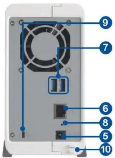
1.2 Hardware Illustration
1.2.1 VS - 12164 / 12156 / 12148 / 12140U-RP Pro+
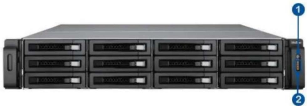
natural_image
Front view of a rack-mounted server rack with multiple drive bays and indicator lights (no visible text or labels)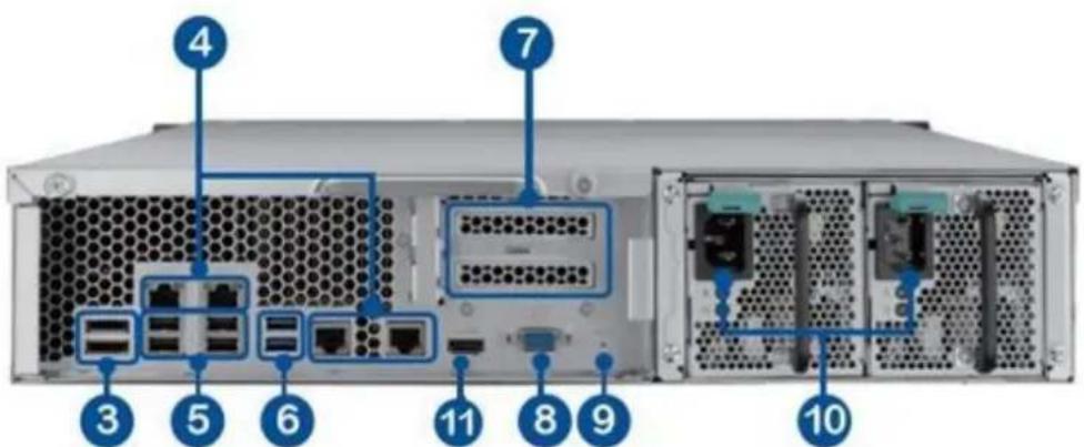
1 Power Buon
3 eSATA x 2 (Reserved)
4 Gigabit LAN x 4
5 USB 2.0 x 4
6 USB 3.0 x 2
7 Expansion Slot x 2 (Reserved)
8 VGA
9 Password & Network Sengs Reset Buon
10 Power Connector x 2
11. HDMI
2 LED Indicators: 10 GbE, Status, LAN, eSATA (Reserved)
1.2.2 VS - 12164 / 12156 / 12148 / 12140U-RP Pro
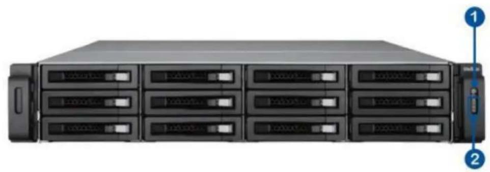
natural_image
Front view of a rack-mounted server rack with multiple drive bays and indicator lights (no visible text or labels)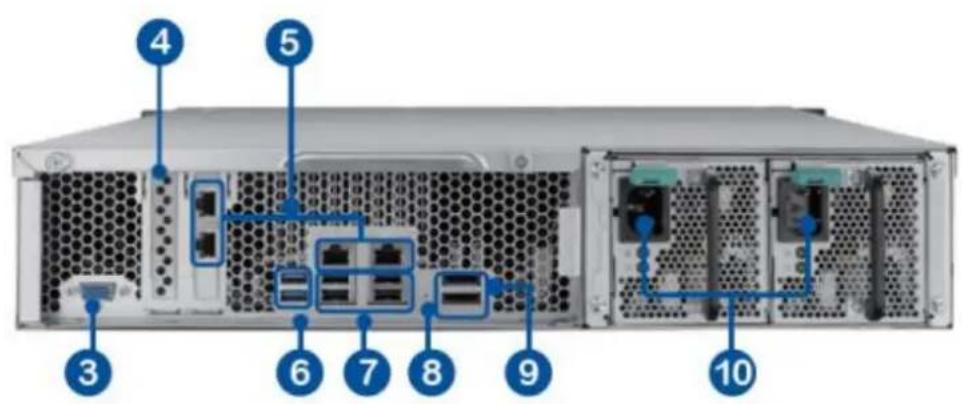
- Power buon
- LED indicators: 10 GbE, Status, LAN, eSATA Select buon(Reserved)
- VGA
- Expansion slot x 1 (reserved)
- Gigabit LAN x 4
- USB 3.0 x 2
- USB 2.0 x 4
- Password & network sengs reset buon
- eSATA x 2 (reserved)
- Power connector x 2
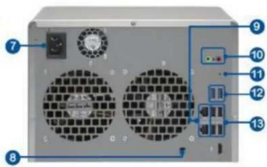
1.2.3 VS - 8148 / 8140 / 8132 / 8124U-RP Pro+
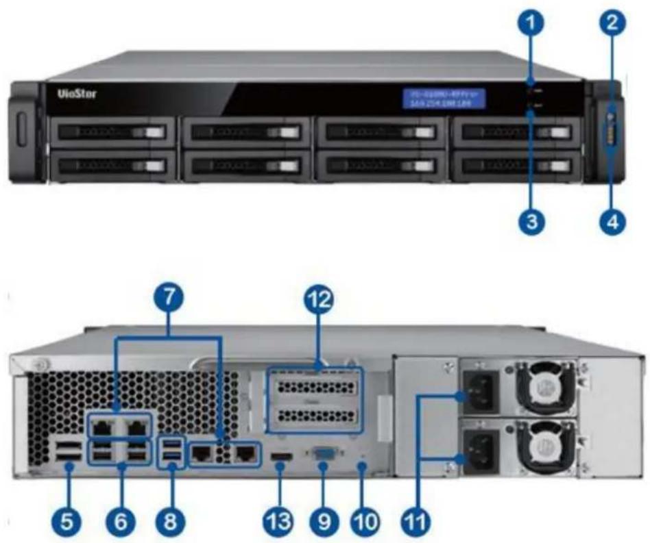
- Enter Buon
- Power Buon
- Select Buon
- LED Indicators: 10 GbE, Status, LAN, eSATA (Reserved)
- eSATA x 2 (Reserved)
- USB 2.0 x 4
- Gigabit LAN x 4
- USB 3.0 x 2
- VGA
- Password & Network Sengs Reset Buon
- Power Connector x 2
- Expansion Slot x 2 (Reserved)
- HDMI
1.2.4 VS - 8148 / 8140 / 8132 / 8124U-RP Pro
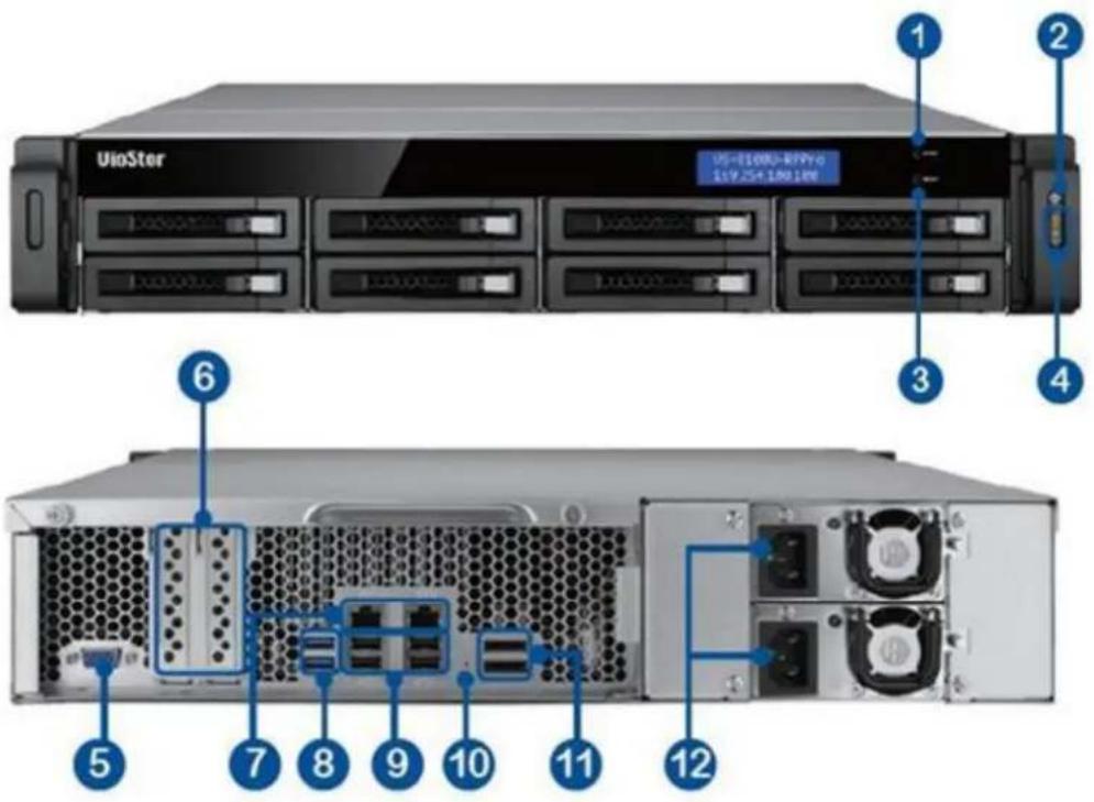
- Enter buon
- Power buon
- Select buon
- LED indicators: 10 GbE, Status, LAN, eSATA(Reserved)
- VGA
- Expansion slot x 2 (reserved)
- Gigabit LAN x 2
- USB 3.0 x 2
- USB 2.0 x 4
- Password & network sengs reset buon
- eSATA x 2 (reserved)
- Power connector x 2
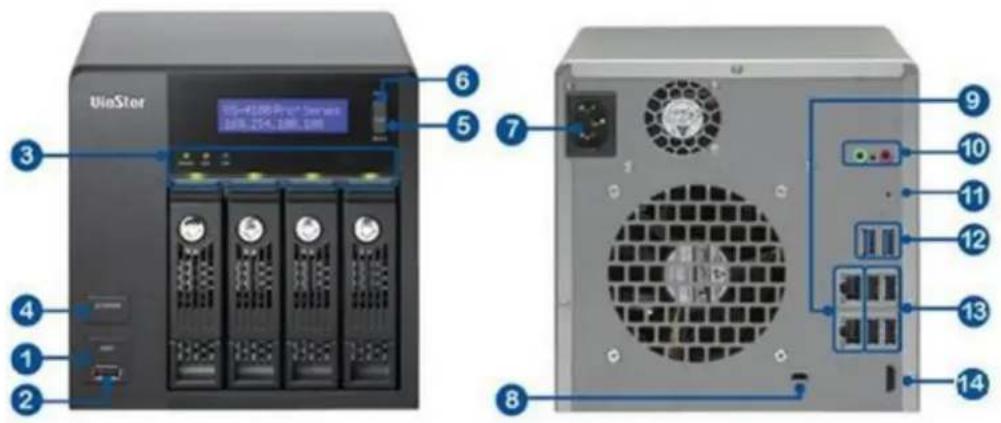
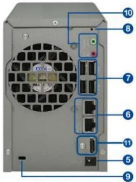
1.2.5 VS - 8148 / 8140 / 8132 / 8124 Pro+
- USB 3.0
- One-touch -video-backup buon
- Power buon
- Hard drive LEDs
- Select buon
- Enter buon
- LED indicators: Status, LAN, USB, eSATA (Reserved), 10 GbE
- Tray lock
- Release buon
- Power connector
- Expansion slot
- Kensington security slot
- VGA
- HDMI
- eSATA x 2 (reserved)
- Gigabit LAN x 2
- USB 2.0 x 4
- USB 3.0
- Password & network sengs reset buon
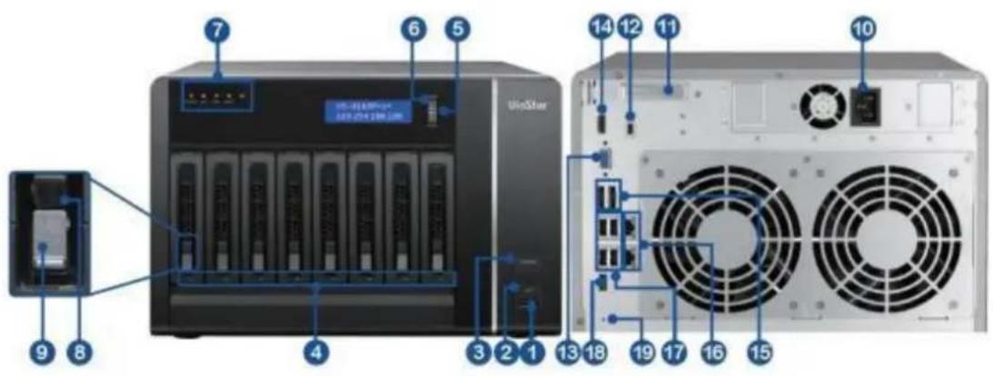
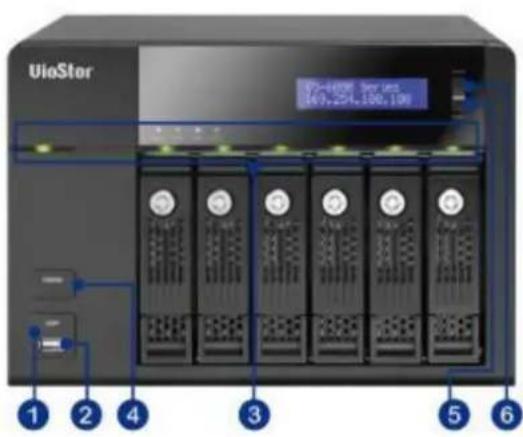
1.2.6 VS - 6120 / 6116 / 6112 Pro+
- One-touch -video-backup buon
- USB 2.0
- LED indicators: Status, LAN, USB, Power, HDD1-6
- Power buon
- Select buon
- Enter buon
- Power connector
- K-Lock Security Slot
- Gigabit LAN x 2
- Audio In/Out
- Password & Network Sengs Reset Buon
- USB 3.0 × 2
- USB 2.0 x 4
- HDMI
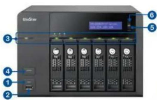
1.2.7 VS - 6020 / 6016 / 6012 Pro

- One-touch -video-backup buon
- USB 2.0
- LED indicators: Status, LAN, USB, eSATA(Reserved), HDD1-6
- Power buon
- Select buon
- Enter buon
- Power connector
- Gigabit LAN x 2
- USB 2.0 x 4
- eSATA x 2 (reserved)
- VGA
- Password & network sengs reset buon
- Kensington security slot
1.2.8 VS - 4116 / 4112 / 4108U-RP Pro+
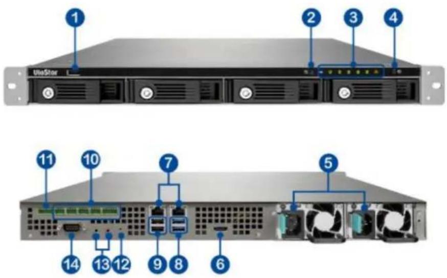
- USB 2.0
- One-touch -video-backup buon
- LED indicators: USB, Status, HDD1-4, LAN
- Power buon
- Power connector
- HDMI
- Gigabit LAN x 2
- USB 3.0 x 2
- USB 2.0 x 2
- DI/DO
- RS-485 (reserved)
- Password & network sengs reset buon
- Audio In/Out
- RS-232 (reserved)
1.2.9 VS - 4016 / 4012 / 4008U-RP Pro
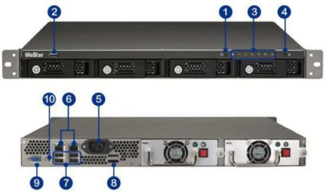
- One-touch -video-backup buon
- USB 2.0
- LED indicators: Status, LAN, USB, eSATA(Reserved), HDD1-4
- Power buon
- Power connector
- Gigabit LAN x 2
- USB 2.0 x 4
- eSATA x 2 (reserved)
- VGA
- Password & network sengs reset buon
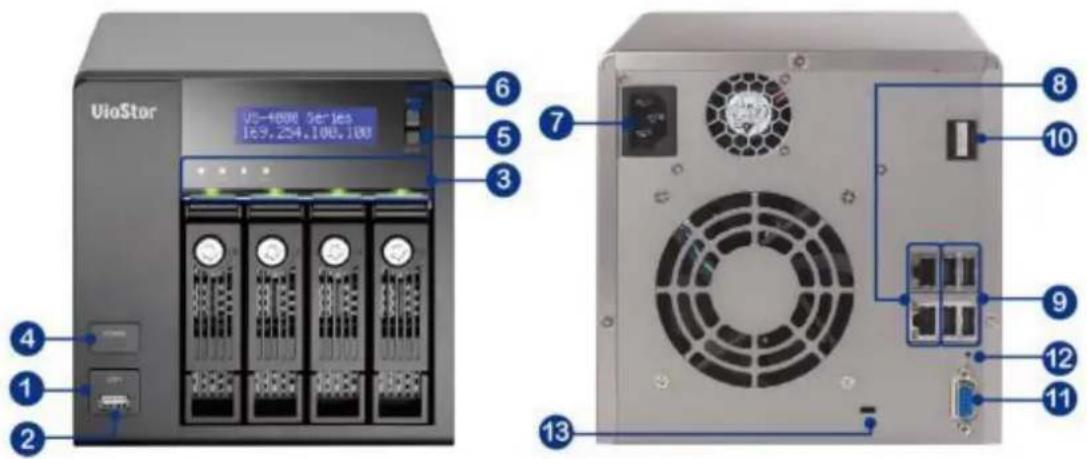
1.2.10 VS-4116/4112/4108 Pro+
- One-touch -video-backup buon
- USB 2.0
- LED indicators: Status, LAN, USB, HDD1-4
- Power buon
- Select buon
- Enter buon
- Power connector
- K-Lock Security Slot
- Gigabit LAN x 2
- Audio In/Out
- Password & network sengs reset buon
- USB 3.0 x 2
- USB 2.0 × 4
- HDMI
1.2.11 VS-4016/4012/4008 Pro
- One-touch-video-backup buon
- USB 2.0
- LED indicators: Status, LAN, USB, eSATA(Reserved), HDD1-4
- Power buon
- Select buon
- Enter buon
- Power connector
- Gigabit LAN x 2
- USB 2.0 x 4
- eSATA x 2 (reserved)
- VGA
- Password & network sengs reset buon
- Kensington security slot
1.2.12 VS-2212/2208/2204 Pro+
- One-touch-video-backup buon
- USB 3.0
- LED Indicators: LAN, HDD1, HDD2
- Power Buon
- Power Connector
- Gigabit LAN x 2
- USB 3.0 x 2
- Password & Network Sengs Reset Buon
- K-Lock Security Slot
- Mic Input/ audio output
- HDMI 1
- HDMI 2 (reserved)
- Alarm input/ output (reserved)
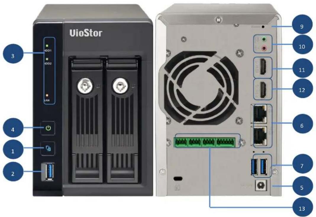
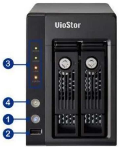
1.2.13 VS-2112/2108/2104 Pro+
- One-touch-video-backup buon
- USB 3.0
- LED Indicators: LAN, HDD1, HDD2
- Power Buon
- Power Connector
- Gigabit LAN x 2
- USB 2.0 x 4
- Password & Network Sengs Reset Buon
- K-Lock Security Slot
- Audio In/Out
- HDMI
1.2.14 VS - 2012 / 2008 / 2004 Pro

- One-touch -video-backup buon
- USB 2.0
- LED indicators: HDD1, HDD2, LAN, eSATA (Reserved)
- Power buon
- Power connector
- Gigabit LAN x 2
- USB 2.0 x 2
- eSATA x 2 (reserved)
- VGA
- Password & network sengs reset buon
- Kensington security slot
1.2.15 VS - S2212 / S2208 / S2204 Pro +
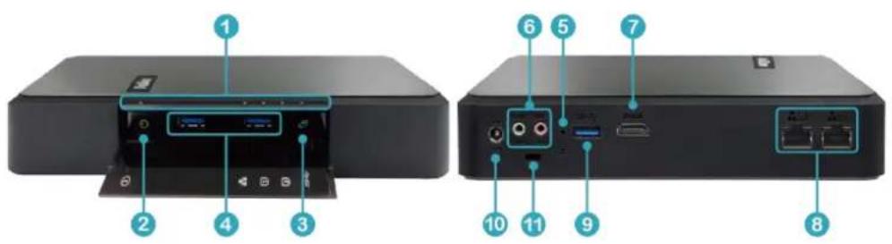
- LED indicators: Status, LAN, HDD1, HDD2, USB (Backup)
- Power buon
- One-touch -video-backup buon
- USB 3.0 x 2
- Password & network sengs reset buon
- Mic Input/ audio output
- USB 3.0
- Gigabit LAN x 2
- HDMI
- Power connector
- K-Lock Security Slot
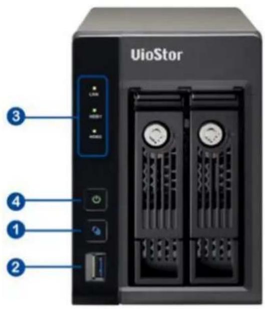
1.2.16 VS-2108/2104L
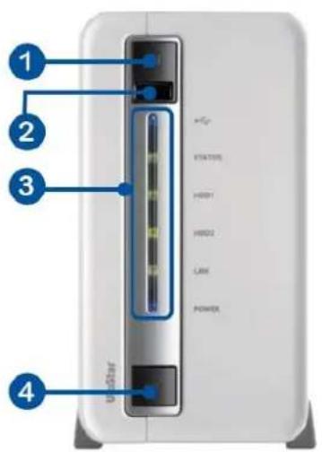
- One-touch-auto-video-backup buon
- USB 2.0
- LED Indicators: USB, status, HDD1, HDD2, LAN, power
- Power buon
- Power connector
- Gigabit LAN
- USB 3.0 x 2
- Password & network sengs reset buon
- K-Lock security slot
- Power cord hook
Chapter 2. Install the NVR
For the informaon of hardware installaon, see the 'Quick Installaon Guide' (QIG) in the product package. The QIG can also be found in the product CD-ROM or QNAP website (hp://www.qnapsecurity.com).
2.1 Personal Computer Requirements
For beer system performance, the computer should at least full the following requirements:
| No. of Channels | Format | CPU | Others |
| 4 | H.264/MPEG-4/MxPEG | Dual core CPU, 2.0GHz or above | ● Operaon system: Microso Windows 8, 7 Professional● Memory: 8GB or above● Graphics Processor: NVIDIA® GeForce® 7600 GT or ATI™ RadeonTM X800 XT or beer● Network port: 100Mbps Ethernet port or above● Web browser: Google Chrome 38.0.2125.104 m, Microso Internet Explorer 10/11 (desktop mode, |
| M-JPEG | Intel Penum 4 CPU, 2.4GHz or above | ||
| 8 | H.264/MPEG-4/MxPEG | Dual core CPU, 2.4GHz or above | |
| M-JPEG | Intel Penum 4 CPU, 2.8GHz or above | ||
| 12 | H.264/MPEG-4/MxPEG | Dual core CPU, 2.8GHz or above | |
| M-JPEG | Intel Penum 4 CPU, 3.0GHz or above | ||
| 16 | H.264/MPEG-4/MxPEG | Quad core CPU, 2.33GHz or above | |
| M-JPEG | Dual core CPU, 2.4GHz or above | ||
| 20 | H.264/MPEG-4/MxPEG | Quad core CPU, 2.6GHz or above | |
| M-JPEG | Dual core CPU,2.6GHz or above | ||
| 32-bit), Mozilla Firefox 33.0CD-ROM drive or Internet DownloadRecommended resoluon: 1280 x 720 pixels or above | |||
| 40 | H.264/MPEG-4/MxPEG | Core i7 CPU 2.8GHz or above | |
| M-JPEG | Quad core CPU 2.33GHz or above | ||
| More than 48 | H.264/MPEG-4/MxPEG | Core i7 CPU 3.4GHz or above | |
| M-JPEG | Quad core CPU 3.0GHz or above |
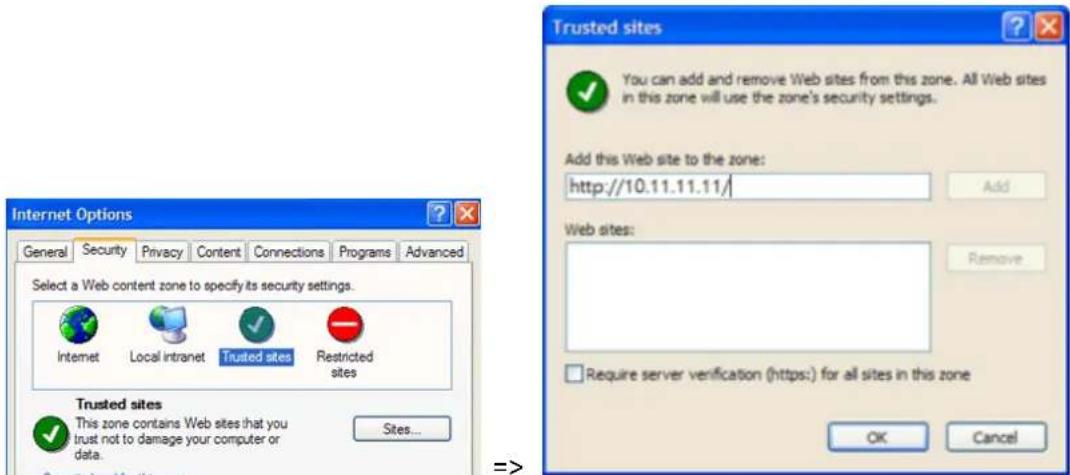
Security Sengs of the Web Browser
Please make sure the security level of the IE browser in Internet Opons is set to Medium or lower.
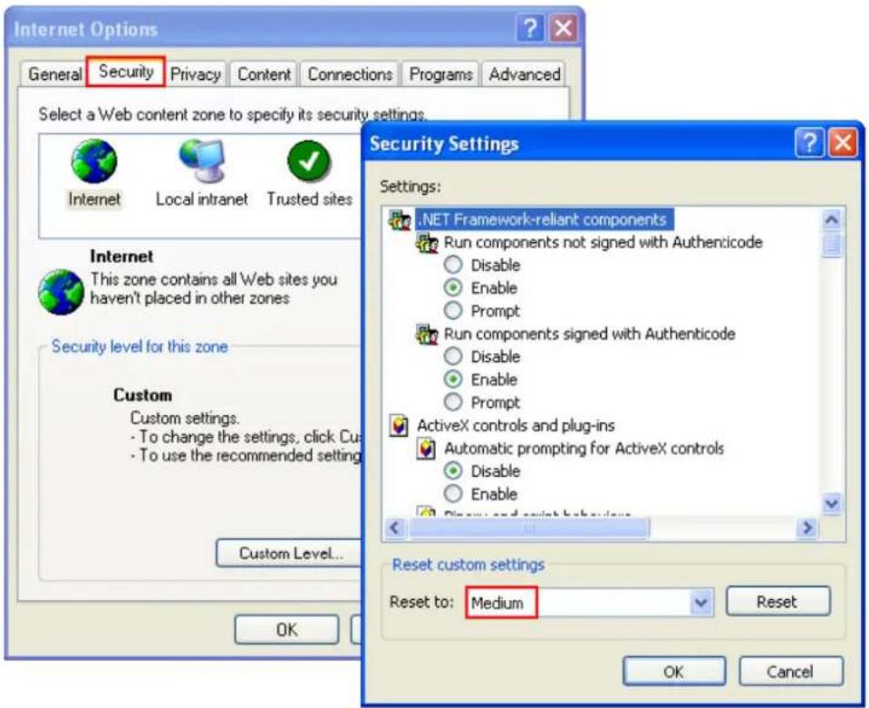
Add your NVR's IP address to the list of Trusted sites.
2.2 Browse CD-ROM
Run the product CD-ROM on a Windows PC to access the Quick Start Guide and user manual, and install the QNAP QVR Client, codec and soware ulies Qnder.
Browse the CD-ROM and access the following contents:
- Codec: The codec for playing AVI videos recorded by the NVR via Windows Media Player.
● Manual: The user manuals of the NVR. - Qnder: The setup program of QNAP Qnder. This tool is used to discover the NVR servers available on the local network and congregate the network sengs of the NVR.
- QIG: View the hardware installaon instrucons of the NVR.
- QVR: The setup program for the QNAP QVR Client, an applicaon to see the live view and play videos recorded by the NVR. If you were unable to install the QNAP QVR Client when connecng to the monitoring/playback page of the NVR, install the plug-in from the CD-ROM.
- Tool: This folder contains IPP library and monitor plug-in. If you failed to install the AcveX plug-in when connecng to the monitoring page of the NVR by an IE browser, install the plug-in from the CD-ROM.
2.3 Hard Disk Drives Compatibility List
This product works with 2.5-inch and 3.5-inch SATA hard disk drives from popular hard disk brands. For the hard disk compatibility list, please visit http://www.qnapsecurity.com/n/en/product_x_grade/.

QNAP disclaims any responsibility for product damage/malfuncon or data loss/recovery due to misuse or improper installaon of hard disks in any occasions for any reasons.
2.4 IP Cameras Compatibility List
For the informaon of supported IP camera models, please visit hp://www.qnapsecurity.com/n/en/product_z_g_qvr/cat_intro.php?hf=0.
2.5 Check System Status
LED Display & System Status Overview
| LED | Color | LED Status | Descripon |
| System Status | Red/Green | Flashes green and red alternately every 0.5 sec | 1. A hard drive on the NVR is being formaed2. The NVR is being inialized3. The system rmware is being updated4. RAID rebuilding is in process5. Online RAID Capacity Expansion is in process6. Online RAID Level Migraon is in process |
| Red | 1. A hard drive is invalid2. The disk volume has reached its full capacity3. The disk volume is going to be full4. The system fan is out of funcon5. An error occurs when accessing (read/write) the disk data6. A bad sector is detected on the hard drive7. The NVR is in degraded read-only mode (2 member drives fail in RAID 5 or 3 member drives fail in RAID 6 conguraon, the disk data can sll be read)8. (Hardware self-test error) | ||
| Flashes red every 0.5 sec | The NVR is in degraded mode (one member drive fails in RAID 1, RAID 5 or two member drives fail in RAID 6 conguraon) | ||
| Flashes green every 0.5 sec | 1. The NVR is starng up2. The NVR is not congured3. A hard drive is not formaed | ||
| Green | The NVR is ready | ||
| LAN | Orange | Orange | The NVR is connected to the network |
| Flashes orange | The NVR is being accessed from the network | ||
| 10 GbE* | Green | (Reserved) | |
| HDD (Hard Drive) | Red/Green | Flashes red | The hard drive data is being accessed and a read/write error occurs during the process |
| Red | A hard drive read/write error occurs | ||
| Flashes green | The hard drive data is being accessed | ||
| Green | The hard drive can be accessed | ||
| USB | Blue | Flashes blue every 0.5 sec | 1. A USB device is detected2. A USB device is being removed from the NVR3. The USB device connected to the front USB port of the NVR is being accessed4. The NVR data is being copied to the external USB device |
| Blue | The USB device connected to the front USB port of the NVR is ready | ||
| O | 1. No USB is detected2. The NVR has nished copying the data to the USB device connected to the front USB port of the NVR | ||
| eSATA | Orange | Flashes | (Reserved) |
*The 10 GbE network expansion funcon is reserved.
Buzzer (can be disabled in 'System Sengs' > 'Hardware' > 'Buzzer')
| Beep sound | No. of Times | Descripon |
| Short beep (0.5 sec) | 1 | The NVR is starng upThe NVR is being shut down (soware shutdown)The reset buon is pressedThe system rmware has been updated |
| Short beep (0.5 sec) | 3 | The NVR data cannot be copied to the external device by pressing the one-touch-auto-video-backup buon. |
| Short beep (0.5 sec), long beep (1.5 sec) | 3, every 5 min | The system fan is out of funcon |
| Long beep (1.5 sec) | 2 | The disk volume is going to be fullThe disk volume has reached its full capacityThe hard drives on the NVR are in degraded modeHard disk rebuilding process starts |
| 1 | The NVR is turned o by force shutdown (hardware shutdown)The NVR has been turned on successfully and is ready |
2.6 System Configuration
Install Qnder
- Run the product CD, the following menu is shown. Click 'Install Qfinder'.
You can also download it from: hp://www.qnapsecurity.com/n/en/product/app_page.php
- Follow the instrucons to install the Finder. Upon successful installaon, run the Finder. If the Finder is blocked by the rewall, unblock it.
- The Finder detects the NVR servers on the local network. If the server has not been initialized, you will be prompted to perform quick setup. Click 'Yes' to connue.
Note: If the NVR is not found, click 'Refresh' to try again.
- Enter the administrator name and password to perform quick setup. The default administrator name and password are as below:
User name: admin
Password: admin
Note: Make sure all the IP cameras are congured and connected to the network.
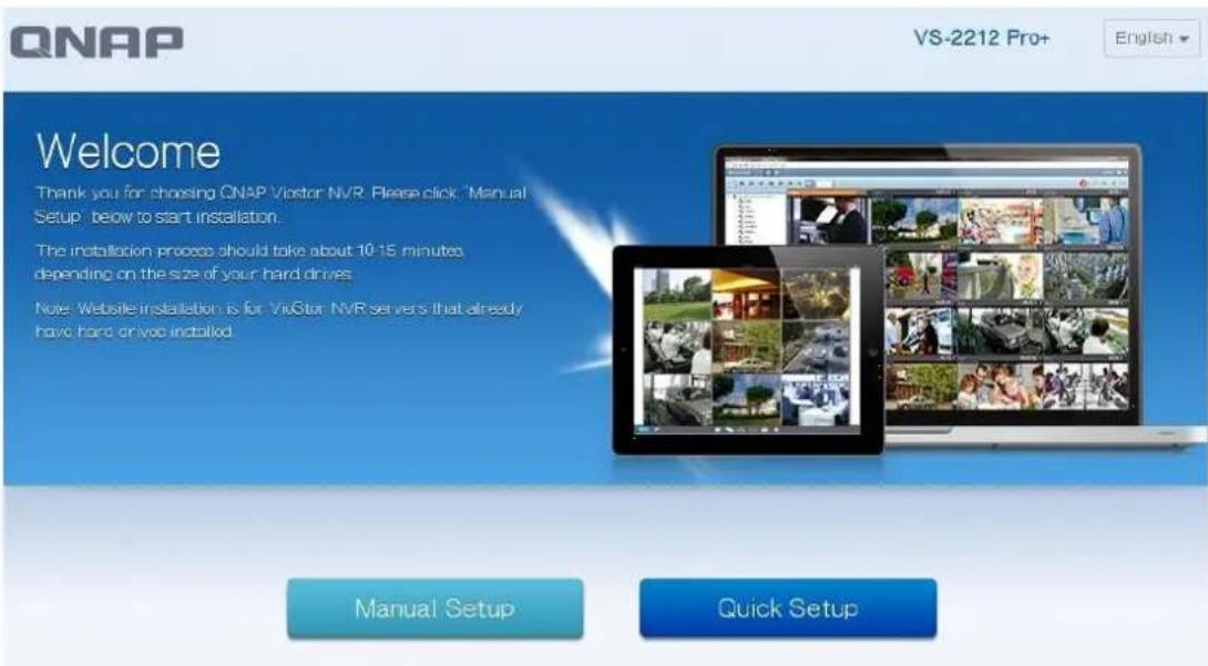
Quick Setup
- The quick setup page will be shown. Click 'Manual Setup' and follow the instrucons to nish the conguraon.

- Click 'Apply' to execute the quick setup.
![ONAP VS-6 (20Prc) logbook - NAME / PASSWORD DATE / TIME NETWORK DECK SUMMARY SUMMARY NAME / PASSWORD Shift Name: Altex 01.25 Username: admin Password: Unchanged DATE / TIME Proxy Name: [GMT+184.00] Beijing, Chongqing, Hong Kong, Shuang Time: Same as the computer/Device Time NETWORK Network: Obits an SF address automatically OK Apply Finish](/content/2026/05/1128063/images/f8751a47f27aa9d99552d6ecac62d5b52ecffdd93f48840405b1c2b9b8a604d4.jpg)
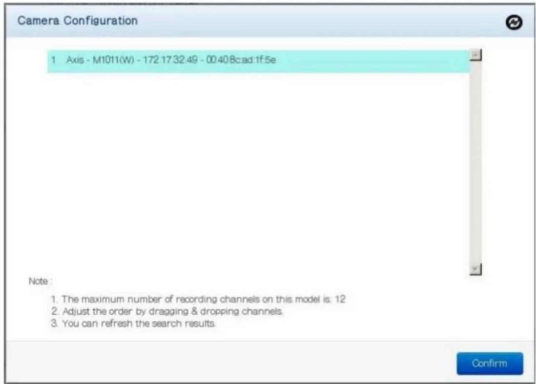
Add IP Cameras
Please follow the steps below to add IP cameras.
- Go to Surveillance Sengs
Please login to the NVR as an administrator and click the Surveillance Sengs
shortcut on the QVR desktop.
-
Go to [Camera Conguraon] -> [Camera Sengs].
-
Click to add an IP camera.
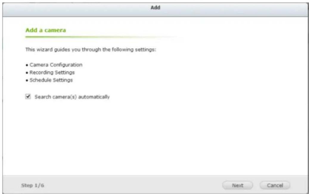
- Follow the steps to add the camera.
Live View
- Click the Monitor shortcut on the QVR desktop to go to monitoring page.
- If it is your rst me connecng to the NVR monitoring page, you will need to install the add-on.
- The live video from the IP cameras congured on the NVR and the recording status of each channel are shown.
Chapter 3. Use the NVR by Local Display
Note: This feature is supported by the VioStor Pro(+) Series NVR only. The models include VS-12164U-RP Pro(+), VS-12156U-RP Pro(+), VS-12148U-RP Pro(+), VS-12140U-RP Pro(+), VS-8148U-RP Pro(+), VS-8140U-RP Pro(+), VS-8132U-RP Pro(+), VS-8124U-RP Pro(+), VS-8148 Pro+, VS-8140 Pro+, VS-8132 Pro+, VS-8124 Pro+, VS-6120 Pro+, VS-6116 Pro+, VS-6112 Pro+, VS-6020 Pro, VS-6016 Pro, VS-6012 Pro, VS-4116U-RP Pro+, VS-4112U-RP Pro+, VS-4108U-RP Pro+, VS-4016U-RP Pro, VS-4012U-RP Pro, VS-4008U-RP Pro, VS-4116 Pro+, VS-4112 Pro+, VS-4108 Pro+, VS-4016 Pro, VS-4012 Pro, VS-4008 Pro, VS-2212 Pro+, VS-2208 Pro+, VS-2204 Pro+, VS-2112 Pro+, VS-2108 Pro+, VS-2104 Pro+, VS-2012 Pro, VS-2008 Pro, VS-2004 Pro, VS-S2212 Pro+, VS-S2208 Pro+, and VS-S2204 Pro+.
Connect a monitor or TV to the NVR via the HDMI or VGA interface to perform PC-less quick conguraon, monitoring, and video playback. To use this feature, follow the steps below:
- Make sure at least one hard drive has been installed on the NVR.
- Connect the NVR to the network.
- Make sure the IP cameras have been congured and connected to the network.
- Connect an HDMI or a VGA monitor or TV (suggested video output resolution: 1920 x 1080)* to the HDMI or VGA interface of the NVR.
- Connect a USB mouse and a USB keyboard (oponal) to the USB ports of the NVR.
- Turn on the NVR.
*All Pro+ series support HDMI interface now.
When the NVR is turned on, the login screen will be shown. Select the language. Enter the administrator name and password. If the NVR has not been congured, skip the login page and enter Quick Conguraon (refer to Chapter 3.1).
Default user name: admin
Default password: admin
English ▼
Click to select the display language. If a USB keyboard is connected,
click to choose the keyboard layout. Click the keyboard icon to enter the necessary informaon if a USB keyboard is not available.


The monitoring page will be shown upon successful login, refer to Chapter 3.3 for details.
3.1 Quick Configuration (Manual Setup or Quick Setup)
If the NVR has not been congured, Quick Conguraon Wizard will be shown.
Follow the instrucons of the wizard to complete the system setup.
Note: All the changes will be eecve only aer applying the sengs in the last step.
3.1.1 Quick Setup
- In the Quick Setup page, the system will search for cameras
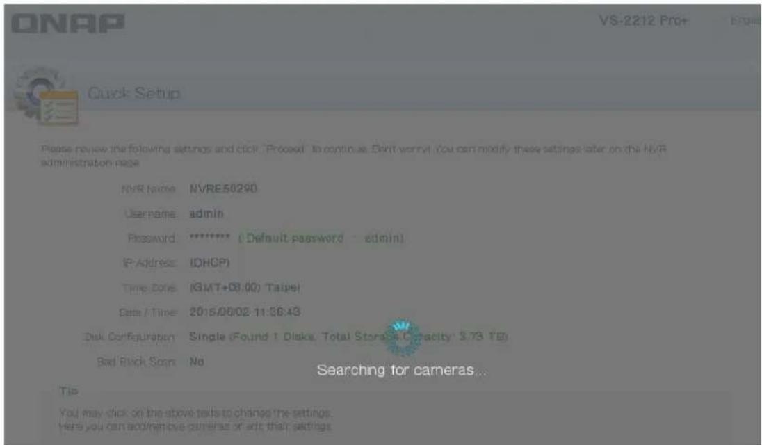
- Aer searching for cameras, a list of discovered cameras will be displayed
- You can now check that all of the NVR and Camera sengs t your needs.

Quick Setup
Please review the following settings and click "Proceed" to continue. Don't worry! You can modify these settings later on the NVR administration page
NVR Name: NVRE50290
Username: admin
Password: ***** ( Default password : admin)
IP Address: (DHCP)
Time Zone: (GMT+08:00) Taipei
Date / Time: 2015/06/02 11:36:43
Disk Configuration: Single (Found 1 Disks, Total Storage Capacity: 3.73 TB)
Bad Block Scan: No
| Status | C | IP Address | Name | Brand | Model | Action |
| 1 | 172.17.32.49 | Camera | Axis | M1011(W) |
Tip
You may click on the above texts to change the settings.
Here you can add/remove cameras or edit their settings.
- To start the setup process, click "Proceed".
3.1.2 Manual Setup
Follow these procedures to setup the NVR.

flowchart
graph LR
    A["NAME / PASSWORD"] --> B["DATE / TIME"]
    B --> C["NETWORK"]
    C --> D["DISK"]
    D --> E["SUMMARY"]
1) Enter the NVR name and administrator password.

Enter the NVR name and administrator password
NVR Name: NVRE50290
Username: admin
Password:
Confirm Password
(Default password: admin)
Show password
Tip
Enter a unique name for the NVR in order to identify it quickly. The NVR name supports up to 14 characters which may include alphabets (A-Z and a-z), numbers (0-9) and dash (-). Space and period () are not allowed
2) Set the me zone, date and me.

Set the date and time
Time Zone (GMT+08:00) Taipei
Date / Time
c Input Manually

- Synchronize with an Internet time server automatically
NTP Server: pool.ntp.org Test
Tip
Enable "Synchronize with an Internet time server automatically" to synchronize the server time with the specified NTP server.
3) Congure the network sengs.

Configure the network settings
Obtain an IP address automatically (DHCP)
c Use static IP address
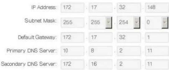
Tip
The default gateway IP is "0.0.0". Enter a correct DNS server IP if the NVR is configured with a static IP. Otherwise, the NVR may fail to synchronize with the NTP server or send alert emails.
4) Select the disk conguraon.

Select the disk configuration

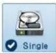
| Slot | Disk Role | Model | Capacity |
| 1 | Member disk | WDC WD40PURX-64GVN- | 3726.02 GB |
Total available storage capacity: 3726.02 GB
File System EXT4
Bad Block Scan
Tip
After selecting the disk configuration and proceeding to the next step, please do NOT remove or install any hard drive(s).
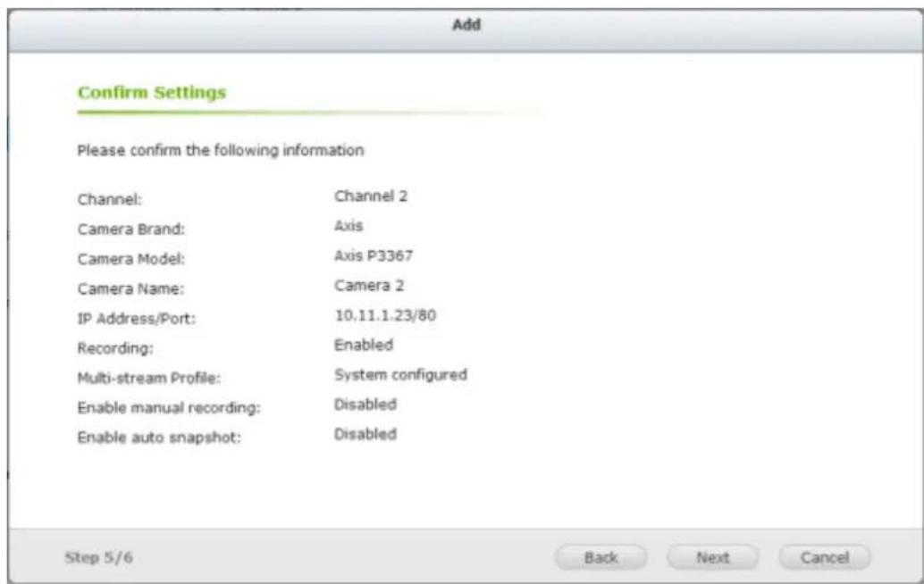
5) In the Summary, you can conrm your sengs and click "Apply" to nish.

SUMMARY
NAME / PASSWORD

NVR Name: NVRE60290
Username: admin
Password: Unchanged
DATE / TIME

Time Zone: (GMT+08:00) Taipei
Time: Synchronize with the NTP server: pool.ntp.org
NETWORK

Network: Obtain an IP address automatically
DISK

Disk Configuration: Single, EXT4
3.2 Surveillance Settings
To manage the surveillance sengs such as administrator password, network and me sengs, click on the monitoring screen. Note that this buon (opon) will be shown for administrator access only.

natural_image
Four-panel collage showing scenes: a man operating a self-service kiosk, emergency medical personnel loading equipment, a factory production line with water bottles, and a truck on an airway (no visible text or symbols)Select the language and click the icons to conjure the sengs.
| 圖示 | 說明 | |
 | Main Menu | |
 | Back to Monitor | |
 | Control Panel | |
 | Surveillance Sengs | |
 | File Staon | |
 | Recording Backup and Storage Expansion | |
 | Background Tasks | |
 | External Devices | |
 | Nocaon | |
 | Opons | |
 | Search | |
 | Help | |
 | Desktop Preferences | |
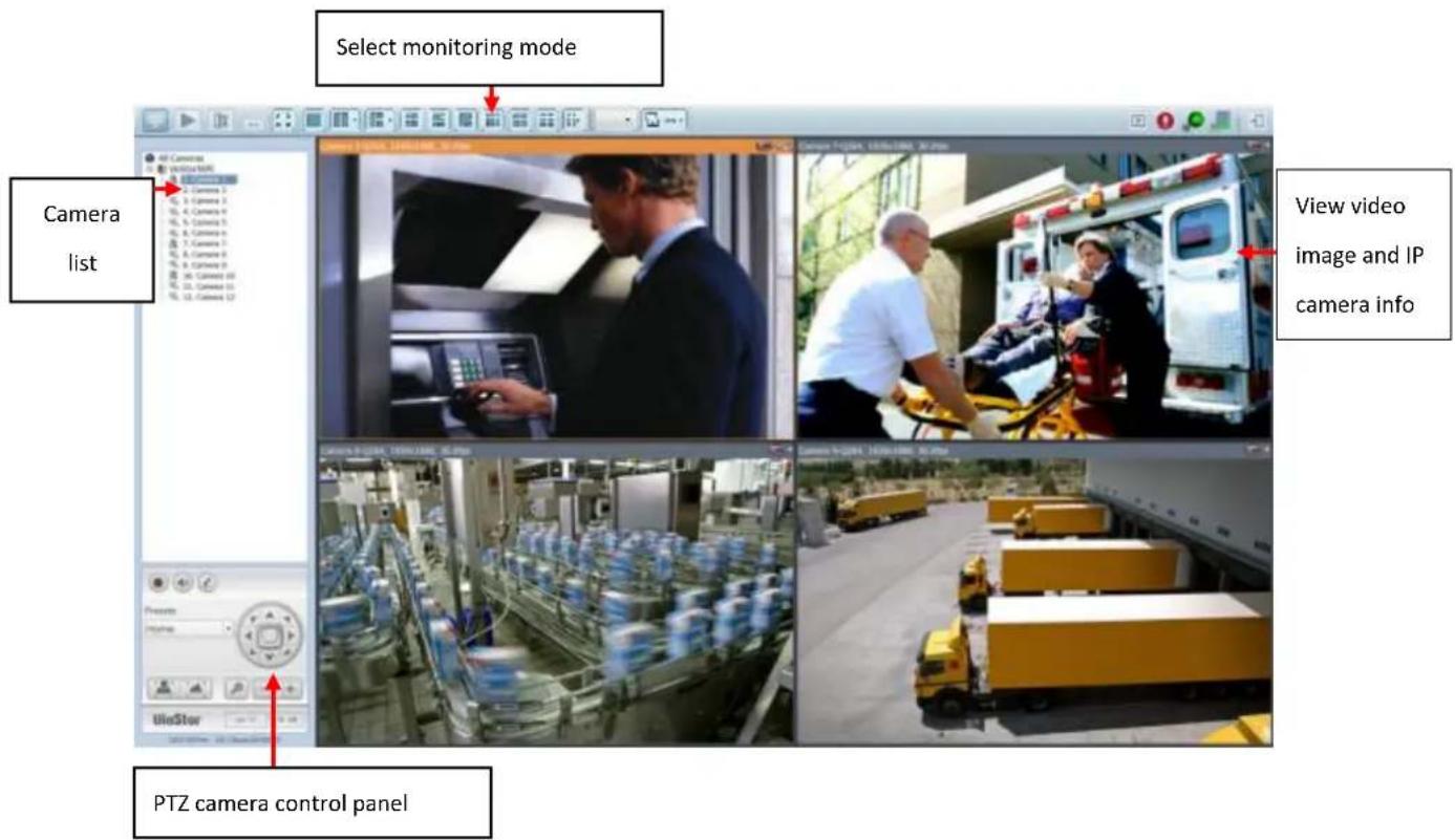
3.3 Monitoring
Upon successful login, the monitoring screen will be shown. Monitor the IP cameras, change the display mode, enable or disable manual recording, control the PTZ cameras, and so on.
| Icon | Descripon | |
 | Monitor:Enter the monitoring page. | |
 | Playback:Enter the playback page. | |
 | Surveillance Sengs:Enter the surveillance sengs page; allows admin access only. | |
 | Hide le panel:Hide the panel on the le of the monitoring page. | |
 | Show le panel:Show the panel on the le of the monitoring page. | |
 | Opons:Congure the event nocaon sengs, video window display sengs, screen resoluon, etc. |
 | CPU Status:Display system CPU usage |
 | Hard drives Status:Display hard drive usage |
 | About:View the server name, NVR model, and rmware version. |
 | Logout:Logout the NVR. |
 | Manual recording:Enable or disable recording on the IP camera. The administrator can select to enable or disable this funcon in ‘Camera Sengs’ > ‘Recording Sengs’ on the web-based administraon interface. |
 | Audio (oponal):Turn on or o the audio support for the monitoring page. |
 | Microphone (oponal):Toggle microphone support for the monitoring page |
Event Nocaon
| Icon | Descripon |
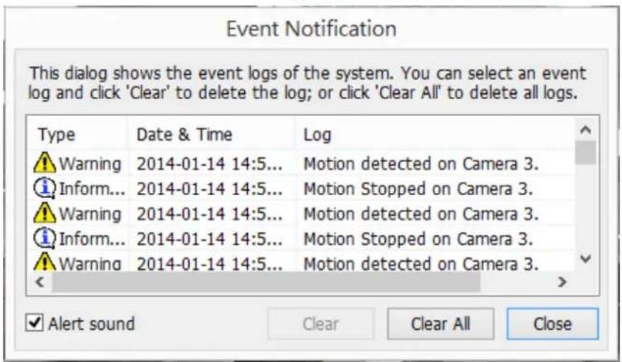
 | Event nocaon:When the alarm recording is enabled and an event is detected, this icon will be shown. Click this icon to view the alert details.The alert sound can be turned on or o. To clear all the logs, click ‘Clear All’. |
The system event logs are shown in this dialog. Click 'Clear' to delete a log; or click 'Clear All' to delete all logs.
| Type | Camera | Date & Time | Log |
| Alarm | 0 | 2010-09-01 11:36:14 | Logical input TB* is triggered |
| Alarm | 0 | 2010-09-01 10:55:23 | Logical input TB* is triggered |
| Alarm | 0 | 2010-09-01 10:35:42 | Logical input ó is triggered |
| Alarm | 1 | 2010-09-01 09:33:32 | Event(s) Triggered on Camera 1. |
| Alarm | 1 | 2010-09-01 09:33:30 | Event(s) Triggered on Camera 1. |
| Alarm | 1 | 2010-09-01 09:33:29 | Event(s) Triggered on Camera 1. |
| Alarm | 1 | 2010-09-01 09:33:27 | Event(s) Triggered on Camera 1. |
| Alarm | 1 | 2010-09-01 09:33:26 | Event(s) Triggered on Camera 1. |
| Alarm | 1 | 2010-09-01 09:33:23 | Event(s) Triggered on Camera 1. |
| Alarm | 1 | 2010-09-01 09:33:21 | Event(s) Triggered on Camera 1. |
| Alarm | 1 | 2010-09-01 09:33:19 | Event(s) Triggered on Camera 1. |
| Alarm | 1 | 2010-09-01 09:33:18 | Event(s) Triggered on Camera 1. |
| Alarm | 1 | 2010-09-01 09:33:15 | Event(s) Triggered on Camera 1. |
| Alarm | 1 | 2010-09-01 09:33:13 | Event(s) Triggered on Camera 1. |
| Alarm | 1 | 2010-09-01 09:33:11 | Event(s) Triggered on Camera 1. |
| Alarm | 1 | 2010-09-01 09:33:09 | Event(s) Triggered on Camera 1. |
| Alarm | 1 | 2010-09-01 09:33:06 | Event(s) Triggered on Camera 1. |
□ Alert sound
Clear All
Close
PTZ Control Panel
The term 'PTZ' stands for 'Pan/Tilt/Zoom'. If the IP camera supports PTZ, use the control panel on the NVR to adjust the viewing angle of the IP camera. These funcons are available depending on the camera models. Please consult the camera's documentaon for details. Note that the digital zoom funcon will be disabled when the PTZ funcon is in use.
| Icon | Descripon |
 | Pan and lt:If the PTZ camera supports pan and lt funcons, click these buons to pan or lt the camera. |
 | Preset posions:Select the preset posions of the PTZ camera. |
 | Zoom out/Zoom in:If the PTZ camera supports zooming, click these buons to zoom in or zoom out. |
 | Digital zoom:Select a channel and click this buon to enable the digital zoom funcon. When enabled, click ‘+’ to zoom in or ‘-’ to zoom out. |
 | Focus control:Adjust the focus control of the PTZ camera. |
 | System informaon:Display system me & date informaon |
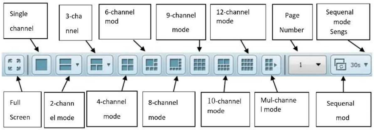
Display Mode
The NVR supports various display modes for monitoring. Click the correct icon to switch the display mode.
| Icon | Descripon |
 | Full screen |
 | Single-channel mode |
 | 2-channel mode (click the downwards arrow to choose another 2-channel mode) |
 | 3-channel mode (click the downwards arrow to choose another 3-channel mode) |
 | 4-channel mode |
 | 6-channel mode |
 | 8-channel mode |
 | 9-channel mode |
 | 10-channel mode |
 | 12-channel mode |
 | 4x4, 5x4, 5x5, 6x5, 8x4, 6x6 channel mode |
 | Select the display page number |
 | Sequential mode. This mode can be used with other display modes.Click to enable or disable sequential mode. Click to denote the me interval of which the channels will be displayed.There are 9 me interval types you can choose: 3 seconds, 5 seconds, 10 seconds, 15 seconds, 30 seconds, 60 seconds, 120 seconds, 150 seconds, 300 seconds. |
Live View Screen
Upon successful conguraon of the IP cameras, enter the monitoring screen to view the live video from the cameras.

natural_image
Exterior view of a large industrial building with surrounding roads and vehicles, labeled 'Engineering Hamcam' in the top-left corner.If the camera supports pan and It funcons, click the channel on the screen and adjust the viewing angle with a mouse. If zooming is supported, scroll the mouse wheel to zoom in or zoom out the video. These funcons are available depending on the camera models. Please consult the camera's documentaon for details.
Camera Status
The camera status is indicated by the icons shown below:
| Icon | Camera Status |
 | Scheduled or connuous recording is in process |
| This IP camera supports audio funcon | |
| This IP camera supports PTZ funcon | |
| Manual recording is enabled | |
| The recording triggered by advanced event management ('Camera Sengs' > 'Alarm Sengs' > 'Advanced Mode') is in process | |
| The alarm input 1 of the IP camera is triggered | |
| The alarm input 2 of the IP camera is triggered | |
| The alarm input 3 of the IP camera is triggered | |
| Moon detecon recording is in process | |
| Digital zoom is enabled |
Connecon Message
If the NVR fails to display the video from an IP camera, a message will be shown in the channel window to indicate the status.
| Message | Descripon |
| Connecng | If the IP camera is located on remote network or the Internet, it may take some me to establish a conneccon to the camera. |
| Disconnected | The NVR cannot connect to the IP camera. Please check the network conneccon of the computer and the availability of the IP camera. If the IP camera is installed on the Internet, open the port on the router or gateway to connect to the IP camera. Please refer to Appendix A. |
| No Permission | You do not have access rights to view this channel. Please login as a user with access rights or contact the system administrator. |
| Server Error | Check the camera sengs or update the rmware of the IP camera (if any). Contact technical support if the error persists. |
Please note:
-
Enabling or disabling manual recording will not affect scheduled or alarm recording tasks. They are independent processes.
-
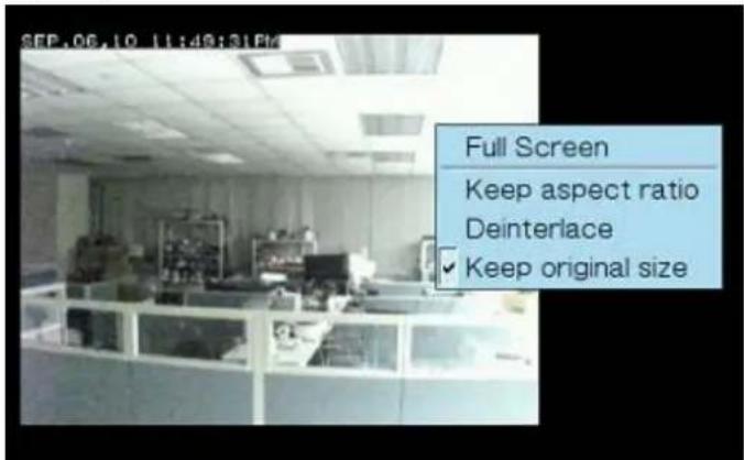
Right click on the IP camera channel and select the following opons:
A. Full screen
B. Keep aspect rao
C. Deinterlace (available on parcular camera models only)
D. Keep original size
E. Dewarp sheye images
Right click on the channel and enable the funcon. Aer that, you can select the Mount type, including wall, ceiling, and oor and then select Dewarping mode, including Panorama (Full View), Panorama (Dual View), and Rectangle.
Remark 1: If the selected mount type is Wall then only Panorama (Full View) and Rectangle are supported in Dewarping mode.
Remark 2: If the selected Dewarping mode is Rectangle, you can use the PTZ control panel to operate PTZ funcons (excluding digital zoom).
F. Dewarp panomorph images: for the specic camera models with panomorph lens Before using this feature, you need to select the 'Enable panomorph support' opon in the recording sengs page. Right click on the channel
and enable the funcon. Aer that, you can select the Mount type, including wall, ceiling, and oor and then select Dewarping mode, including Perimeter mode, Quad mode, and PTZ mode.
Remark 1: To see a list of camera models that support panomorph lenses, please visit hp://www.qnapsecurity.com/n/en/qa/con_show.php?op=showone&cid=128.
Remark 2: This funcon is only available when the resoluon of the video stream is higher than 640x480 on the monitoring page.
Remark 3: If Dewarping mode is in PTZ mode, then in the channel, you can use the PTZ control panel or mouse (by holding down the mouse le buon, and then moving the mouse or turning the mouse wheel) to change viewing angles or to zoom in/out of the screen. If the Dewarping mode is in Quad mode, the above methods can also be applied to operate PTZ funcons in each divided screen.
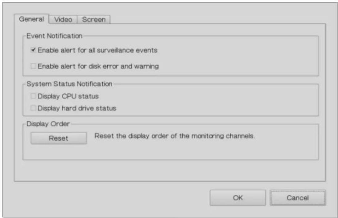
Opons
To congure advanced monitor sengs, click .

The following opons are listed under the 'General' tab.
Event Nocaon:
√ When ‘Enable alert for all surveillance events’ opon is enabled and a

surveillance event is triggered, the alert icon will be instantly shown on the monitoring page. Click the icon to view the alert details.
√ Aer enabling ‘Issue nocaon when the disk reaches maximum operaon me set below’ in System Tools -> Hard Disk SMART, you can then ‘Enable alert for disk error and warning’ to receive alarm nocaons if hard drive events occur.
● System Status Nocaon:
√ Display CPU status: will display the CPU status as seen below

√ Display HDD status: will display the hard drive status as seen below

- Display Order: Click ‘Reset’ to repriorize the monitoring channels to default.
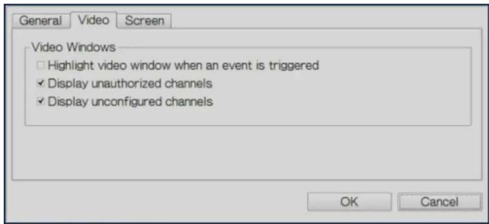
The following opons are provided under the 'Video' tab.
● Highlight the video window when an event is triggered: The video window will ash if an event is triggered.
- Display unauthorized channels: Select this opon to show channels that the user does not have the access rights to.
- Display uncongured channels: Select this opon to show uncongured channels.
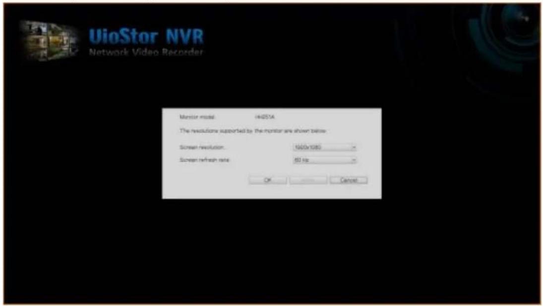
The NVR automacally detects the resoluon sengs supported by the connected monitor and will use the opmum sengs. To change the screen resoluon, click 'Sengs' under the 'Screen' tab. Aer conguring the resoluon sengs, the monitoring screen will be shown.
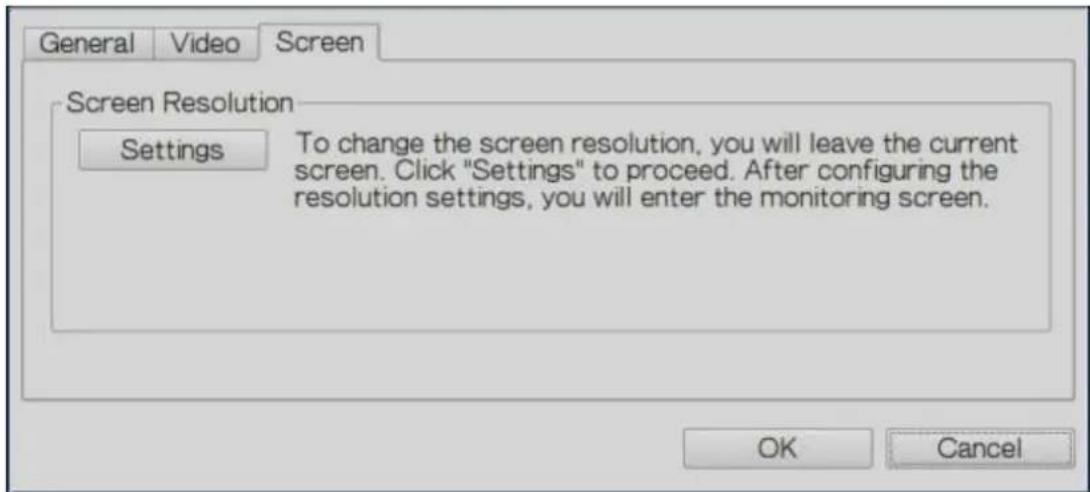
If the monitor model cannot be detected, the NVR will provide resolution opons of 1920x1080, 1400x1050, 1280x1024, and 1024x768.
3.4 Video Playback
The videos on the NVR can be played using the local display. To use this feature, click on the monitoring screen. Most of the icons on the playback screen are the same as those on the monitoring screen. Please refer to Chapter 3.2 for the icon descripon.
Note: The playback access rights to the IP cameras are required to play the videos. Login to the NVR as the admin and edit the playback access rights in 'User Management' using the web-based administraon interface.
When the playback screen is shown, select a camera channel on the NVR. Next, select the start and end me of the video and click to start searching. The videos that match the search criteria will be played automacally.
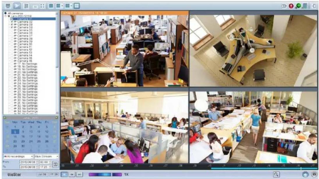
Note: The number of days between the start and end dates must be less than or equal to 2.
Playback Sengs:

Play, pause, stop, reverse play a video le, or select to play the previous or next le. When playing a video, use the scroll bar to adjust the playback speed or click on the digital zoom icon to zoom in/out the video.
Right click on the IP camera channel to select the following opons:
- Full screen
- Keep aspect rao
- Deinterlace (available on parcular camera models only)
- Keep original size
- Dewarp sheye images
Right click on the channel and enable the funcon. Aer that, you can select the Mount type, including wall, ceiling, and oor and then select Dewarping mode, including Panorama (Full View), Panorama (Dual View), and Rectangle.
Remark 1: If the Mount type is Wall, only Panorama (Full View), and Rectangle are supported in Dewarping mode.
Remark 2: If Dewarping mode is Rectangle, you can use the PTZ control panel to operate PTZ funcons (excluding digital zoom).
- Dewarp panomorph images: for the specific camera models with panomorph lens
Before using this feature, you need to select the 'Enable panomorph support' opon in the recording sengs page. Right click on the channel and enable the funcon. Aer that, you can select the Mount type, including wall, ceiling, and oor and then select Dewarping mode, including Perimeter mode, Quad
mode, and PTZ mode.
Remark 1: To discover what camera models can be installed with panomorph lenses, please visit
hp://www.qnapsecurity.com/n/en/qa/con_show.php?op=showone&cid=128.
Remark 2: The funcon is only available when the video stream resoluon is higher than 640x480 on the monitoring page.
Remark 3: If Dewarping mode is in PTZ mode, for the channel, you can use the PTZ control panel or mouse (by holding down the mouse le buon, and then moving the mouse or turning the mouse wheel) to change viewing angles or zooming in/out the screen. If Dewarping mode is in Quad mode, the above methods can also be applied to operate PTZ funcons in each divided screen.
3.5 Video Conversion & Export
The NVR supports converng video les to AVI format and saving the les to an external USB storage device.
Note:
- To use this feature, connect a USB storage device to the front USB port of the NVR and ensure the device has been correctly formed.
- Access rights to play the IP camera videos are required to convert the video les.
Follow the below steps to export IP camera video les from the NVR and convert the les to an AVI le.
- Enter the playback interface of the NVR. Select a camera channel on the NVR.
Click (Convert to AVI le).
- Select the IP camera.
- Specify the start and end mes of the video les.
- Select the export format.
Standard AVI le: Convert recording les to standard AVI le. More me is needed to export, but no additional codecs are required.
Optimized QNAP AVI le: Convert les using an enhanced QNAP codec. Less me is needed to export, but the QNAP codec is required.
QNAP Encrypted AVTI le: Protect the le with password protecon and encrypon
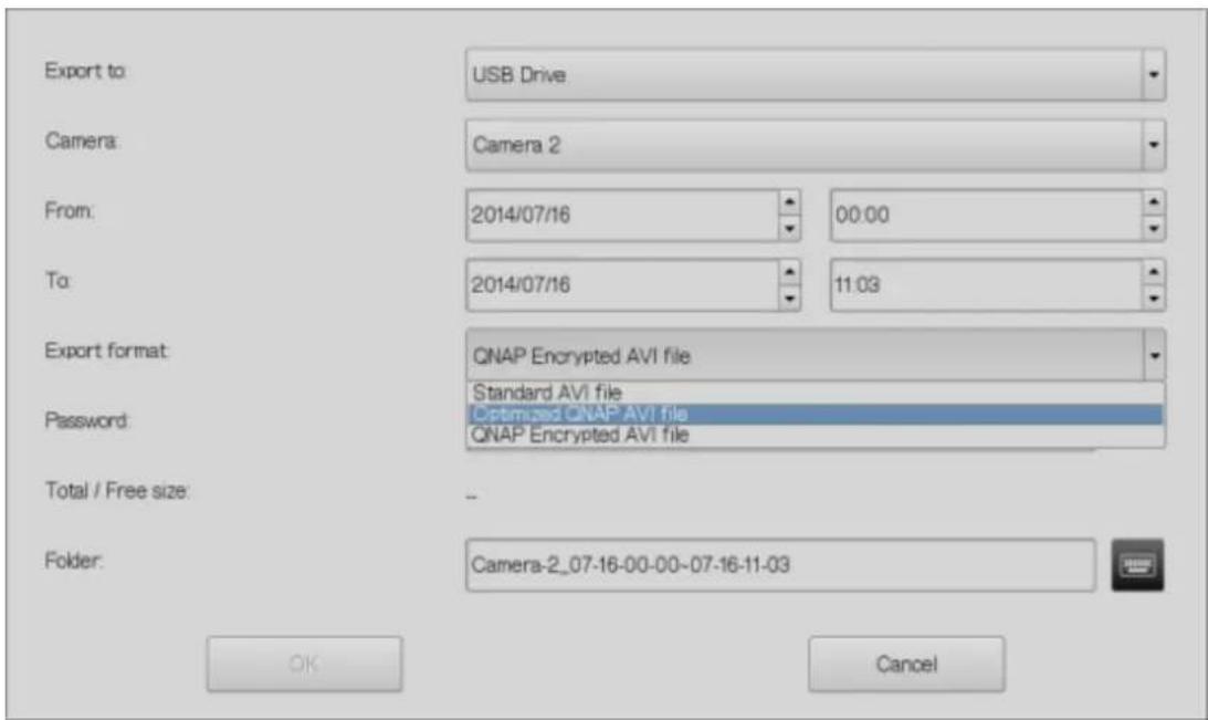
- Enter the le name of the video le.
- Click 'OK' to convert the video les to an AVI le and save them to the external USB storage device.
Chapter 4. QVR Basics and Desktop
4.1 Introducing QVR
Built on a Linux foundaon, the QVR, QNAP VioStor Recording system has been designed around an optimized kernel to deliver high-performance services sasfying your needs in live view, recording, playback and more.
The intuitive, mul-window and mul-tasking QVR GUI makes it incredibly easy to manage your VioStor NVR, ulize its rich surveillance applicaons, and install a rich set of applicaons in the App Center on demand to expand your VioStor NVR experience.
QNAP VioStor NVR has many professional features for remote monitoring, recording, and surveillance tasks under diverse environments but also funcons with great simplicity. The QNAP VioStor NVR allows users to choose suitable network cameras for various situations. Businesses can enjoy high exibility in deploying their ideal surveillance solutions with the broad-ranged oerings of compatible IP cameras.
QNAP VioStor NVR also oers:
- An intuitive GUI with mul-window, mul-tasking, and mul-applicaon support
● Real-time monitoring and recording (video/audio) from mulple IP cameras
● Cross plaorm surveillance center - Mul-server monitoring (up to 128 channels)
- Interacve control buons
- Instant playback
● Same-screen IP camera conguraons
● Playback and speed control with shule bar
● Preview videos with thumbnails
● Intelligent video analytics (IVA) - Digital watermarking
● Live monitoring, playback on Android and iOS mobile devices with Vmobile
● Advanced event management
● Real-me SMS and email alert
● Install-on-demand applicaons via the App Center
4.2 Connect to the NVR
Follow the below steps to connect to the monitoring page of the NVR.
- Run the Qfinder. Double click the name of the NVR, or enter the IP address of the server in your web browser to connect to the monitoring page.
-
Enter the user name and password to login the NVR.
Default user name: admin
Default password: admin -
To view the live video in your web browser, please add the NVR IP address to your list of trusted sites. When accessing the NVR via Internet Explorer, you will be prompted to install the AcveX add-on.
-
To view the live video with Google Chrome, Mozilla Firefox or by using the QNAP QVR Client on Windows PC, please visit hp://www.qnapsecurity.com/download.asp to download and install the QNAP QVR Client for Windows rst.
-
To view the live video on Mac, please visit hp://www.qnapsecurity.com/download.asp to download and install the QNAP QVR Client for Mac.
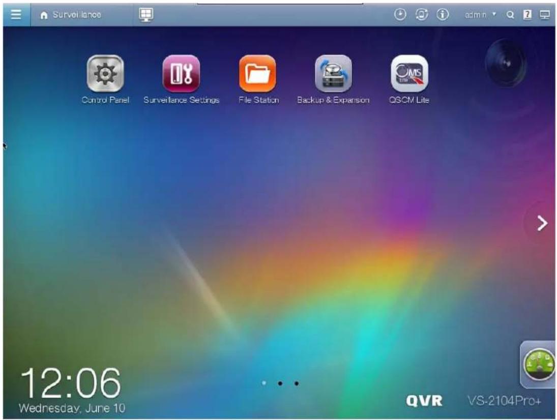
4.3 Using the QVR Desktop
Aer you nish the basic NVR setup and login to the NVR, the following desktop will appear. Each main desktop feature is introduced in the following seconds.
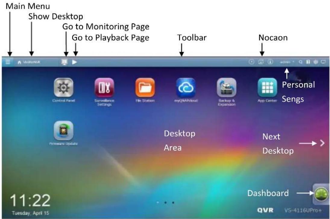
Toolbar
Main Menu
Click to show the Main Menu. It includes three parts: 1) QNAP applicaons; 2)
system features and sengs. Items under "APPLICATIONS" are developed by QNAP to enhance your NVR experience. Items under "SYSTEMS" are key system features designed to manage or optimize your NVR. These applicaons can add funconalies to the NVR (for their introducon, please refer to their descripon at the App Center.) Click the icon from the menu to launch the selected applicaon.
Show Desktop

Click to minimize or restore all open windows and
show the desktop.
Monitor page

Click to enter monitor page
Playback page

Click to enter playback page
Background Task

Click to review and control all tasks running in the background (such as HDD
SMART scanning.)

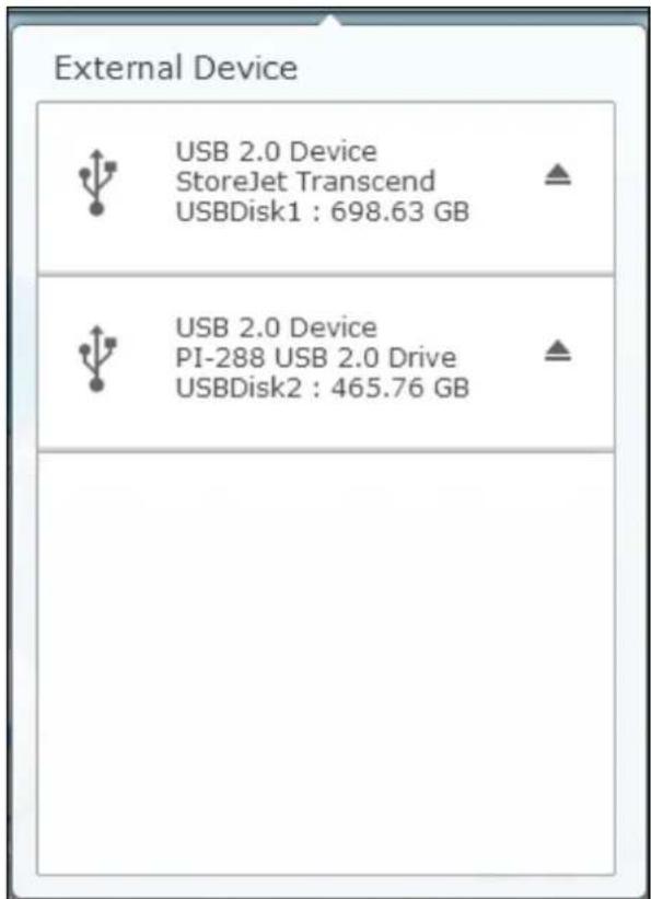
External Devices

Click to list all external devices that are connected to the NVR via its USB ports.
Click the device listed to open the File Staon for that device. Click the "External Device" header to open the External Device page for relevant sengs and operaons
(for details on the File Staon, please refer to the chapter on File Staon.) Click to eject the external device.
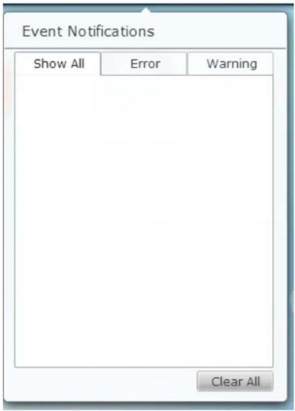
Nocaon and Alerts
Click to check for recent system errors and warning nocaons. Click “Clear All” to clear all entries from the list. To review all the historical event nocaons, click the “Event Nocaons” header to open the System Logs. For more details regarding System Logs, please refer to the chapter on System Logs.
Personal Seng
admin
Admin Control: Click to customize your user specific sengs, change your user password, restart/shut down the NVR or log out your user account.
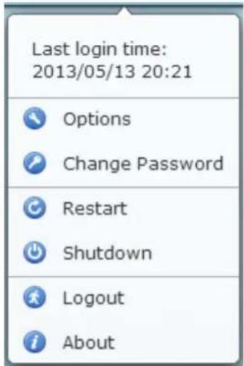
- Opons():

Options
A. Prole: Specify your user email address.
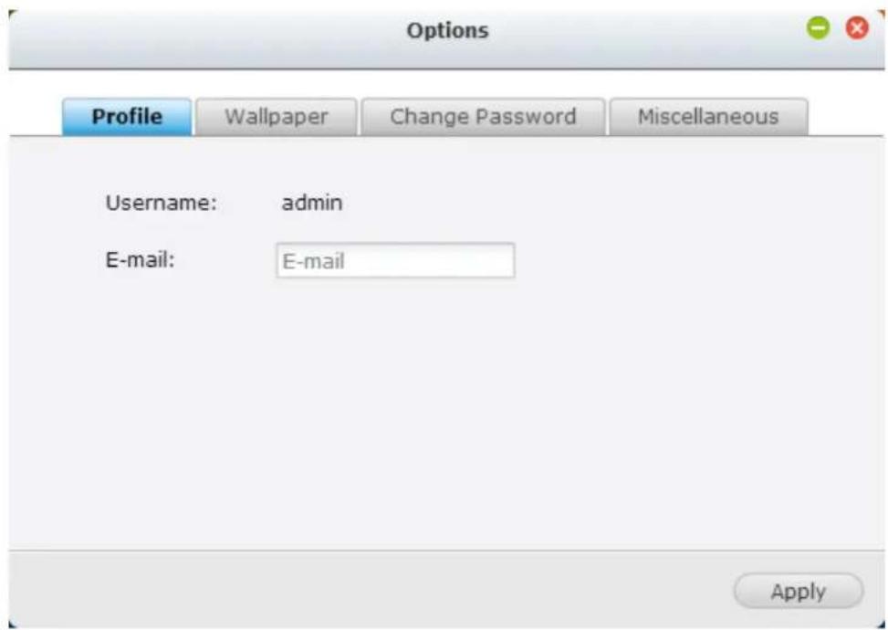
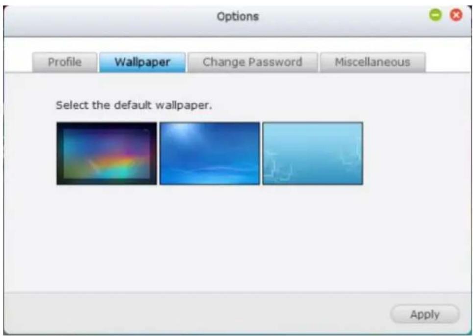
B. Wallpaper: Change the default wallpaper or upload your own wallpaper.
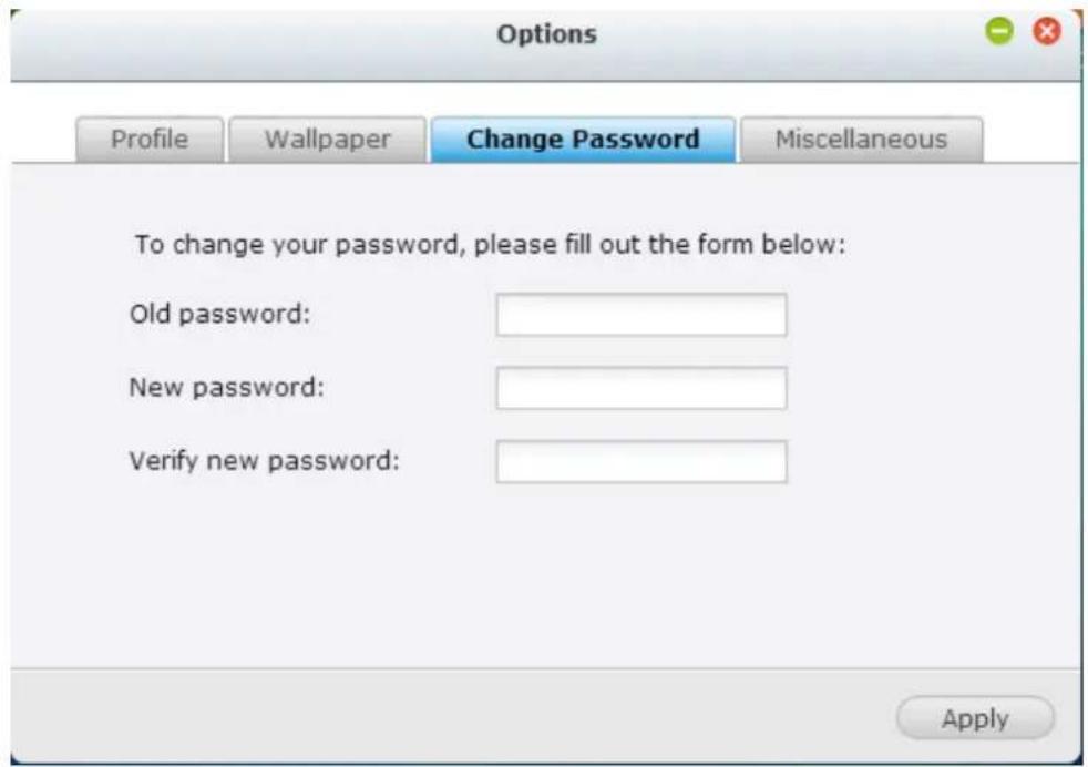
C. Change Password: Change your login password.
D. Miscellaneous:
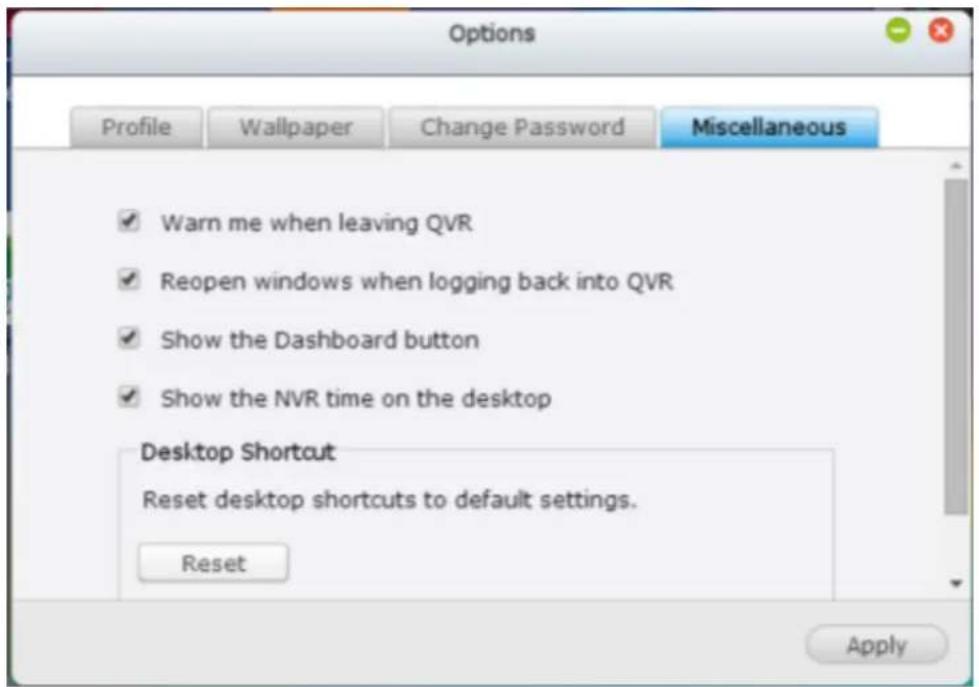
- Warn me when leaving QVR: Check this opon, and users will be prompted for conrmaon each me they leave the QVR Desktop
(such as clicking the back icon () in the browser or
close the browser (☐). It is recommended to check this opon.
● Reopen windows when logging back into QVR: Check this opon, and
all the current desktop sengs (such as the "windows opened before your logout") will be kept aer you login the NVR the next me.
● Show the desktop switching buon: Check this opon to hide the next


desktop buon ( ) and last desktop buon ( ) and only
display them when you move your mouse cursor close to the buons.
● Show the Dashboard buon: If you would like to hide the Dashboard

buon ( ) at the boom right side of the NVR Desktop,
uncheck this opon.
● Show the NVR me on the desktop: If you prefer not to show the NVR me at boom le side of the desktop, uncheck this opon.
- Change Password: Click to change your
login password.
-
Restart: Click to restart your NVR.
-
Shutdown: Click to shut down your NVR.
-
Logout: Click to log yourself out.
-
About: Click to check the NVR model details
including, rmware version, HDDs already installed and available (empty) bays.
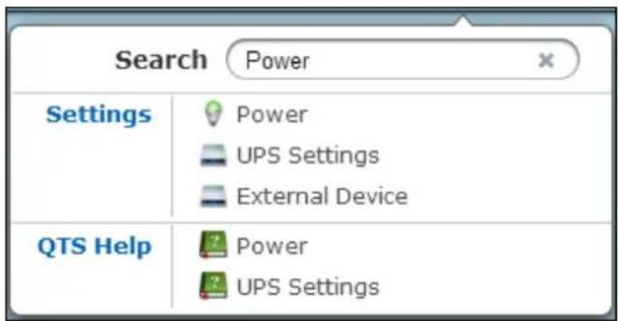
Search
Click and enter a feature-specific keyword in the search box to search for the desired funcon and its corresponding online help. Click the result in the search box to launch the funcon or open its online QVR help.
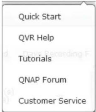
Online Resource
Click to display a list of online references, including the Quick Start Guide, QVR Help, Tutorials, and QNAP Forum. Customer Service is available here.
Language
Click to choose your preferred language for the UI.

Desktop Preferences
Click to choose the applicaon icon displaying style and select your preferred applicaon opening mode on the desktop. Applicaon icons can be switched

natural_image
App icon with grid and diamond shapes on blue background (no text or symbols)between small thumbnails ( ) and detailed thumbnails
window mode.
For the tab mode, the window will be opened to t the enre NVR Desktop and only one applicaon window can be displayed at once, while in the window mode, the applicaon window can be resized and reshaped to a desirable style. Please note: if you login the NVR using a mobile device, only the tab mode is available.
Desktop Area
You can remove or arrange all applicaons on the desktop, or drag one applicaon

icon over the top of another to put them in the same folder
Next Desktop and Last Desktop
Click the next desktop buon ( ) (right side of the current desktop) or the last desktop buon ( ) (le side of the current desktop) to switch between desktops. The posion of the desktop is indicated by the three dots at boom of the desktop
Dashboard
All important system and HDD stascs can be reviewed on the QVR Dashboard.
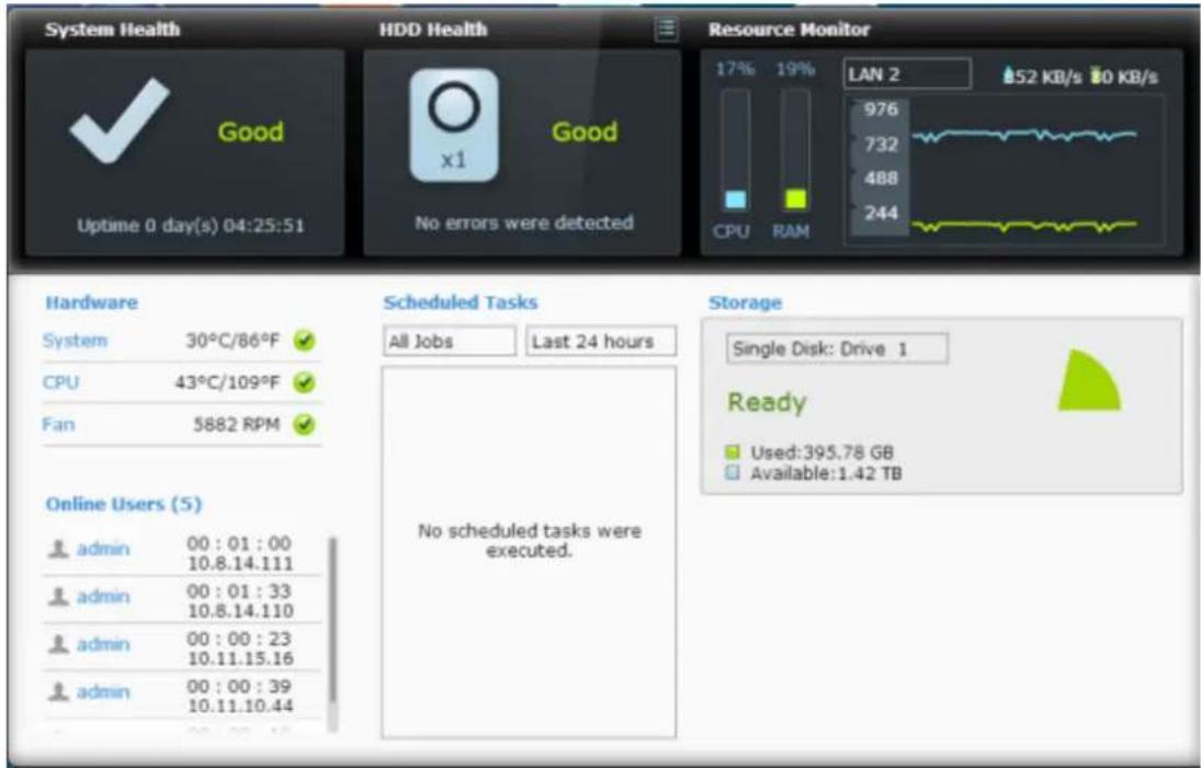
- System Health: The status of the NVR system is indicated in this secon. Click the header to open the "System Status" page.
- HDD Health: The status of the HDDs currently installed in the NVR will be shown in here. X1 means that only one HDD is currently installed in the NVR. For mulple HDDs installed in the NVR, the status indicated is only for the HDD with the worst condition. Click the “HDD Health” header to open the “HDD SMART” page in Storage Manager to review the status of each HDD. For details on the Storage Manager, please refer to the chapter on Storage Manager. Click the icon to switch between the “HDD Summary” page and the HDD status indicator. Please note that the color of the HDD symbol will change based on HDD health.
- Resource Monitor: The CPU, RAM and bandwidth usage is displayed here. Click the "Resource Monitor" header to open the corresponding page in System Status for details. Please note: if the port trunking feature is acvated, the bandwidth stascs are the combined usage of all NICs.
- Storage: The shared folder (top ve largest folders), volume and storage stascs are summarized here. Click the "Storage" header to open the corresponding page in System Status for details.
- Hardware: The system and HDD temperatures, fan speeds and hardware usages are summarized here. Please note: stascs listed here vary based on the NVR model purchased. Click the "Hardware" header to open the corresponding page in "System Status" for details.
● Online Users: All users currently connected to the NVR are listed here. To
disconnect or block a user or IP, right click the user and choose the desired acons. Click the “Online Users” header to open the corresponding page in “System Logs” for details.
- Scheduled Tasks: Tasks scheduled are listed here. Click the task dropdown list to list only the chosen category and the me drop down list to specify the me range for tasks to be listed.
Tip:
- All widgets within the Dashboard can be dragged onto the desktop for monitoring specific details.
● The Dashboard will be presented dierently on different screen resolutions.
● The color of the Dashboard button will change based on the status of system
health for quick recognition ( )

Slide-in window: System-related news will be displayed on the window at boom right side of the desktop. Click the update to check the relevant details.
Chapter 5. Remote Monitoring
Use Google Chrome, Mozilla Firefox, or Microso Internet Explorer and QNAP QVR Client to monitor the IP cameras of the NVR.
Note: QNAP QVR Client is a client applicaon developed by QNAP Systems, inc., used to locally or remotely access QNAP NVR servers for performing video monitoring and playback funcons. Users can nd and download this applicaon under the 'Ulity' secon of the QNAP Security website at
hp://www.qnapsecurity.com/download.asp.
Important Noce:
- Before using the NVR, install the hard disks in the server correctly and nish the disk formang and conguraon. Otherwise, the server will not funcon properly.
- If your Windows OS is Windows Vista, Windows 7 or above, it is suggested to turn o UAC (User Account Control) for full surveillance funcons. Please refer to hp://www.qnapsecurity.com/faq_detail.asp?faq_id=503.
5.1 Monitoring Page
Upon successfully logging in, click on the QVR desktop to go to the monitoring page. Select the display language. Start to congregate the system sengs and use the monitoring and recording funcons of the server.

The following table consists of the icons and their descripons in the monitoring page.
| Icon | Descripon |
 | QVR Desktop:Return to the QVR desktop. |
 | Monitor:Enter the monitoring page. The administrator can grant access rights to the users to see the live view. |
 | Playback:Enter the video playback page. The administrator can grant access rights to the users to play back the videos. |
 | Event nocaon:When the alarm recording is enabled and an event is detected, this icon will be shown. Click this icon toview the alert details. |
 | Dual-display mode:The NVR supports dual-display mode. (This funcon can only be used when the computer or the host is connected to mulple monitors.) |
 | Server list:Up to 128 channels from mulple QNAP NVR servers can be monitored. |
 | E-map:Upload E-map(s) and indicate the locaons of the IP cameras. The administrators are allowed to edit and view the E-map(s). Other users can only view the E-map(s). |
 | Opons:Congure the advanced sengs of the monitoring page. Specify the source of the video/audio stream, event nocacn, and snapshot folder. |
Note:
- Click the event nocaaon icon to view the event details, enable or disable the alert sound or clear the event logs.
Interacve Control Buons
Whenever you move the mouse cursor over a camera channel, the supported funcon buons of the camera will show up for quick access.
| Icon | Descripon |
 | Manual recording (Note 1):Enable or disable manual recording on the selected channel. The administrator can enable or disable this opon on the surveillance sengs page. |
 | Snapshot (Note 2):Take a snapshot on the selected channel. When the picture is shown, right click on it to save it to the computer. |
 | Audio (oponal):Turn on/o the audio support for the monitoring page. For more informaon about the compatibility of this feature, please visithp://nvr.qnapsecurity.com/n/en/product_z_g_qvr/cat_intro.php?hf=old. |
 | Two-way audio (oponal):Turn on/o the two-way audio support for the monitoring page. For more informaon about the compatibility of this feature, please visithp://nvr.qnapsecurity.com/n/en/product_z_g_qvr/cat_intro.php?hf=old.Please note: the two-way audio funcon is currently only supported by the latest version of Internet Explorer. |
 | Dewarp sheye images:For specie sheye cameras (Note 3) and the specie camera models with panomorph lens (Note 4), you can enable/ disable the dewarping funcon. Aer enabling the funcon, you can then select mount type, dewarping mode. |
 | PTZ mode:1. Click & Go: Click on the camera screen at any point to align the center of the screen using this point as the target.2. PTZ: Pan/Tilt/Zoom camera control.3. Auto cruising: This feature is used to congregate the PTZ cameras to cruise according to the preset posions and the staying me set for each preset posion.4. Enable live tracking: Available on Panasonic NS202(A) cameras.5. Disable live tracking: Available on Panasonic NS202(A) cameras. |
 | Preset posion: Select the preset posions of PTZ cameras. |
 | Digital zoom (Note 5):Enable/disable digital zoom. |
 | Instant playback:On the Live-view page, whenever you want to look back to check suspicious events of a camera channel you just missed, just hit ‘Instant Playback’ buon to bring up the window to review recent feeds. While you don’t have to switch to the playback page to do so, you can sll have full live views of other channels simultaneously. |
 | Same-screen IP camera conguraons:On the Live-view page, you can directly congregate an IP camera’s recording schedules when needed without leaving the Live-view page, maintaining seamless monitoring so you won’t miss any suspicious events. |
 | Camera informaon:1. Properes (Note 6): Congure other monitoring opons.2. Locate in E-map: Highlight camera icon on E-map.3. Connect to camera homepage. |
 | ROI (Region of Interest):This funcon provides you two kinds of magnied viewing modes to choose from. You can choose 5-split or 7-split, then draw a square to see an interesng region. Click [plit mode]. Click [plit mode]. Click [plit mode. Click [plit mode. |
Note:
- Enabling or disabling the manual recording feature will not act the scheduled or alarm recording.
- By default, the snapshots are saved in 'My Documents' or 'Documents'> 'Snapshots' on Windows.
If the snapshot me is inconsistent with the actual me that the snapshot is
taken, it is caused by the network environment but not a system error.
3. Applied to specific sheye cameras
Aer enabling the feature, you can select Mount type, including wall, ceiling, and oor and then select Dewarping mode, including Panorama (Full View), Panorama (Dual View), and Rectangle. For more informaon, please refer to hp://www.qnapsecurity.com/n/en/trade_teach/con_show.php?op=showone&cid=27.
Remark 1: If the Mount type is Wall, only Panorama (Full View), and Rectangle are supported in Dewarping mode.
Remark 2: If Dewarping mode is Rectangle, you can use PTZ control panel to operate PTZ funcons, excluding digital zoom.

natural_image
Overhead view of a cluttered office desk with electronic devices and tools (no visible text or symbols)4. Applied to specific camera models with panomorph lens
Before using this feature, you need to select the 'Enable panomorph support' opon in the camera conguraon page. Aer enabling the feature, you can select Mount type, including wall, ceiling, and oor and then select Dewarping mode, including Perimeter mode, Quad mode, and PTZ mode.
Remark 1: To know the camera models that can be installed with panomorph lens, please visit
hp://www.qnapsecurity.com/n/en/qa/con_show.php?op=showone&cid=128.
Remark 2: The funcon is only available when the resolution of the video stream is higher than 640x480 on the monitoring page.
Remark 3: If Dewarping mode is PTZ mode, for the channel, you can use PTZ control panel or mouse (by clicking and holding down the mouse le buon, and then moving the mouse or turning the mouse wheel) to change viewing angles or zooming in/out the screen. If Dewarping mode is Quad mode, the above methods can also be applied to operate PTZ funcons in each divided screen.
-
When the digital zoom funcon is enabled on mulple IP cameras, the zooming funcon will be aected if the computer performance is not high enough.
-
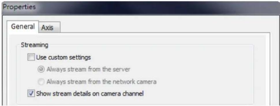
Properes
A. Streaming:
I. Use custom sengs
i. Always stream from the server: Select this opon to stream the audio and video data from the NVR. If the computer cannot connect to the IP cameras, select this opon to allow the NVR to stream the data. No extra port forwarding is required; however, the performance of the NVR may be aected.
II. Always stream from the network camera: If the NVR and the IP cameras are connected to the same local network, select this option to stream the video data from the IP cameras. If the NVR, the IP cameras, and the PC are located behind a router, virtual server, or rewall, congregate port forwarding on the IP cameras to use certain ports.
III. Show stream informaon
Show video codec, frame rate, bit rate, current recording days and current recording size of this channel.
B. OSD Setngs: Specify the font color of the text on the channels.

C. Display Mode:
- Fit image to window: Select this open to t an image to the browser window. Specify to keep the aspect rao or not when resizing an image.
II. Display image in original size: Select this opon to display an image in its original size if it is smaller than the browser window. You can also specify how an image will be resized if it is larger than the browser
window.
i. Shrink image to t window, maintaining aspect rao
ii. Shrink image by 1/2, 1/4, 1/8... and so on to t window

D. Video Processing: Turn on 'Deinterlace' when there are interlaced lines on the video.
E. Video Resoluon: Specify to adjust the resoluon automacally or use a xed resoluon. To adjust the resoluon automacally, the NVR will select the resoluon seng* which best ts the size of your web browser window. Note that 'Stream from network camera' will not be available if the IP camera does not support streaming from camera or video resoluon conguraon. Both opons will not be available if the IP camera does not support mulple streams.
![Video Resolution Stream from server Stream from network camera ● Adjust resolution automatically ○ Fixed resolution VGA[MJPG]](/content/2026/05/1128063/images/1a0d229c2a473cc4f4f9201bd99640350827eb470d6a5b72f79b6dfff409bcd7.jpg)
*If an IP camera supports dierent resoluon sengs, the NVR will select the smallest resoluon larger than (or equal to) the size of the browser window. If all the supported resoluon sengs of an IP camera are smaller than the browser window, the largest resoluon will be selected.
F. Let me choose other cameras to apply the same settings: Select this option to apply the changes to other IP cameras. Note that some sengs may not be applied if the IP camera does not support the features, such as streaming from camera or video resolution conguraon.
□ Let me choose other cameras to apply the same settings
![Properties General Axis Streaming Use custom settings Always stream from the server Always stream from the network camera Show stream details on camera channel OSD Settings OSD text color: Display Mode Fit image to window Keep aspect ratio Display image in original size. If the image is larger than the window, do the following: Shrink image to fit window, maintaining aspect ratio Shrink image by 1/2, 1/4, 1/8...and so on to fit window Video Processing Deinterlace Video Resolution Stream from server Stream from network camera Adjust resolution automatically Fixed resolution VGA[M]PG Let me choose other cameras to apply the same settings OK Cancel](/content/2026/05/1128063/images/fe7a5d22f0ad106baeb3d0b79883ec64b937011dc6e32952bd5afbc591933a78.jpg)
5.1.1 Live Video Window
The live videos of the IP cameras congured on the NVR are shown on the monitoring page. Click the channel window to use the features supported by the IP camera, e.g. digital zoom or pan/lt/zoom.

natural_image
Four-panel collage showing scenes: a man in business attire interacting with a machine, emergency vehicle inspection, water production line with barrels, and autonomous delivery trucks (no visible text or symbols)Camera Status
The camera status is indicated by the icons shown below:
| Icon | Camera Status |
| The NVR and IP camera are connected. | |
| The NVR is trying to establish conncon to the IP camera. | |
| The NVR cannot connect to the IP camera. | |
| The congured acon triggered by alarm event is in process | |
| Alarm sengs are congured, but not in process | |
| Scheduled or connuous recording is in process | |
| Schedule recording is enabled, but not in process | |
| Manual recording is enabled | |
| Manual recording is not in process | |
| This IP camera supports audio funcons | |
| This IP camera supports PT funcon with connuous PT | |
| This IP camera supports PT funcon without connuous PT | |
| The alarm input 1 of the IP camera has been triggered | |
| The alarm input 2 of the IP camera has been triggered | |
| The alarm input 3 of the IP camera has been triggered | |
| A moving object has been detected | |
| Digital zoom is enabled |
Connecon Message
When the NVR fails to display the video of an IP camera, a message will be shown in the channel window to indicate the status.
| Message | Descripon |
| No Permission | No access right to view the monitoring channel. Please login as an authorized user or contact the system administrator. |
| Server Error | Please check the camera sengs or update the rmware of the IP camera (if any). Contact the technical support if the error persists. |
5.1.2 Display Mode
The NVR supports dierent display modes for viewing the monitoring channels.
flowchart
graph TD
    A["Single channel"] --> B["Full Screen"]
    C["3-channel"] --> D["2-channel el mode"]
    E["6-channel mod"] --> F["4-channel mode"]
    G["9-channel mode"] --> H["8-channel mode"]
    I["12-channel mode"] --> J["10-channel mode"]
    K["Page Number"] --> L["Mul-channel l mode"]
    M["Sequenal mode Sengs"] --> N["Sequenal mod"]
*You can congregate the sequential interval in the sequential mode sengs.
5.1.3 PTZ Camera Control Panel
The term ‘PTZ’ stands for ‘Pan/Tilt/Zoom’. If an IP camera supports the PTZ feature, use the control panel on the NVR to adjust the viewing angle of the IP camera.
These funcons are available depending on the camera models. Please refer to the user manual of the IP cameras for more informaon. Note that the digital zoom funcon will be disabled when the PTZ funcon is in use.
QVR 5.0 and above hides the PTZ control panel by default. You can enable the PTZ control panel in the opons on the monitoring page.
Note: When you enable mul-display mode and the live view window is too small to show interactive control buons, please enable PTZ control panel to control the
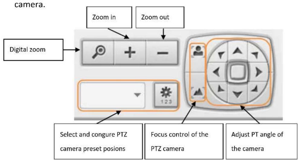
| Icon | Descripon |
 | Digital zoom:Select a channel and click this buon to enable the digital zoom funcon. This funcon can also be enabled by right clicking the  display window of the PTZ camera. Press zoom in or zoom out. You can also use the mouse wheel to operate the digital zoom funcon. display window of the PTZ camera. Press zoom in or zoom out. You can also use the mouse wheel to operate the digital zoom funcon. |
 | Zoom out/zoom in :If the PTZ camera supports opcal zoom, you can press  to opcally zoom out or to opcally zoom out or  buon to opcally zoom in.When digital zoom funcon is enabled, you can press buon to opcally zoom in.When digital zoom funcon is enabled, you can press  digitally zoom out or digitally zoom out or  buon to digitally zoom in. buon to digitally zoom in. |
 | Select and congregate PTZ camera preset posions:Select and view the preset posions of the IP camera from the list. For some camera models, you can congregate PTZ camera preset posions on the monitoring page. For more informaon about the compatibility of PTZ cameras for preset posions conguraon, please visithp://nvr.qnapsecurity.com/n/en/product_z_g_qvr/cat_intro.php?hf=old. For other PTZ camera models please refer to the user manual of the IP camera. |
5.1.4 Multi-server Monitoring
Follow the steps below to use the mul-server monitoring feature of the NVR.

- Click 'Server List' on the monitoring page.
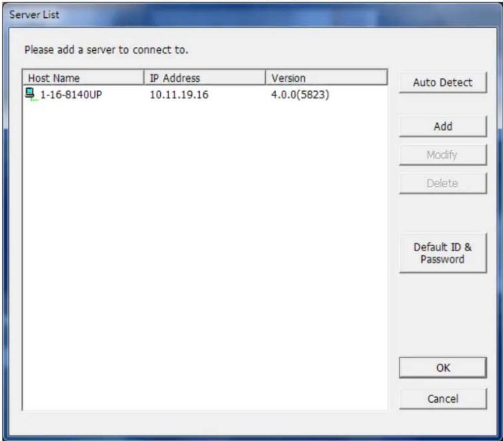
A. Click 'Auto Detect' to search for the NVR on the LAN and add the server to the server list.
B. Click 'Add' to add the NVR to the server list.
- Up to 128 channels from mulple NVR servers can be added for monitoring.
5.1.5 Monitor Settings
To congure advanced monitor sengs, click .

Options
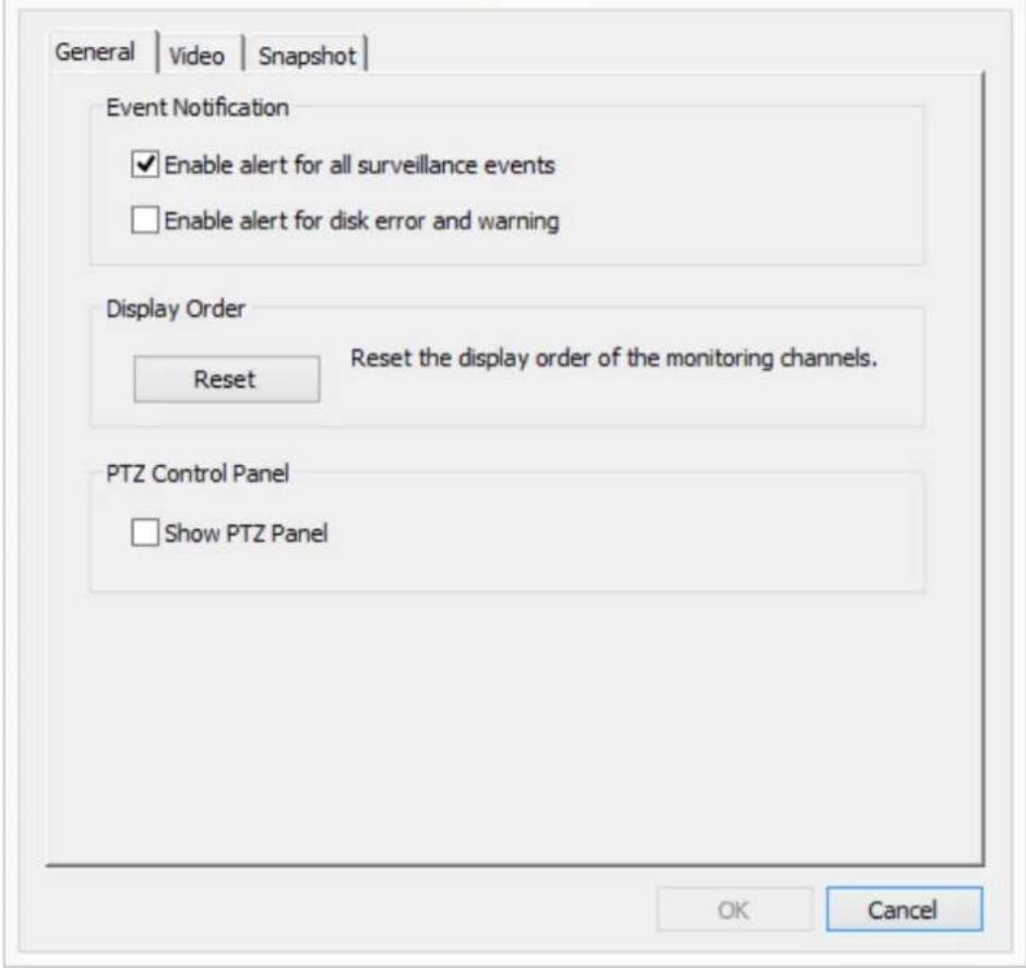
The following opons are provided under the 'General' tab.
Event Nocaon:
■ When ‘Enable alert for all surveillance events’ opon is enabled and a

surveillance event is triggered, the alert icon will be shown on the monitoring page instantly. Click the icon to view the alert details.
■ After enabling ‘Issue nocaon when the disk reaches maximum operaon me set below’ in System Tools -> Hard Disk SMART, you can then ‘Enable alert for disk error and warning’ to receive alarm nocaons when hard drive events occur.
- Display Order: Click ‘Reset’ to repriorize the monitoring channels to the default order.
● PTZ Control Panel: Select to show or hide the PTZ control panel.
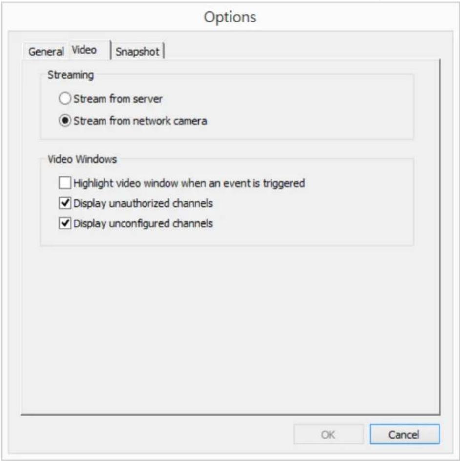
The following opons are provided under the 'Video' tab.
- Streaming
Stream from the server: If the IP camera cannot be connected from the computer, select this opon and the video will be streamed from the NVR. This opon does not require extra port mapping conguraon; but may influence the performance of the NVR.
Stream from IP camera: If the NVR and the IP cameras are located on the same LAN, select this opon to stream the video from the IP camera. Note that the port forwarding sengs on the IP cameras must be congured if the NVR, IP cameras, and the computer are located behind a router, a virtual server, or a rewall.
- Video Windows
■ Highlight the video window when an event is triggered: The video window will ash if an event is triggered.
■ Display unauthorized channels: Select this opon to show the channels that the user does not have the access right to monitor.
■ Display uncongured channels: Select this opon to show the channels
that have not been congured.
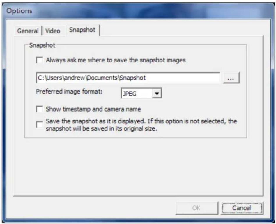
The following opons are provided under the 'Snapshot' tab.
- Snapshot
- Specify the locaon where the snapshots are saved and the image format (JPEG, BMP or TIFF).
- Show mestamp and camera name: Show the mestamp and the camera name on the snapshot.
- Save the snapshot as it is displayed: Select this opon to save the snapshot as it is displayed on the window. Otherwise, the snapshot will be saved in its original size.
5.1.6 Instant Playback
On the Live-view page, whenever you want to look back to check suspicious events of a camera channel you just missed, just hit the ‘Instant Playback’ buon to bring up the window to review recent feeds. While you don’t have to switch to the playback page to do so, you can sll have full live views of other channels simultaneously.
- Please wait a moment for the system to process your request (depends on available network bandwidth).
- Reverse play is used by default. When playing to the event me, you can drag the playback control buon (gray part) to the right to change to normal playback.
- You can double click on a specific me on the meline to change the playback me.
Note: The range of searchable me is 24 hours.
5.1.7 Same-screen IP Camera Configurations
On the Live-view page, you can directly congregate IP camera sengs when needed without leaving the Live-view page, maintaining seamless s monitoring so you won't miss any suspicious events.
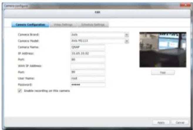
- Please wait a moment for the system to process your request (depends on available network bandwidth).
- You can modify camera, recording and schedule sengs. The sengs will come into eect aer clicking 'Apply.'
5.1.8 Auto Cruising
The auto cruising feature of the NVR is used to conjure the PTZ cameras to cruise according to the preset posions and the staying me set for each preset posion.
To use the auto cruising feature, follow the steps below.

- On the monitoring page of the NVR, click
and select 'Connect to
camera homepage' to go to the conguraon page of the PTZ camera.
-
Set the preset posions on the PTZ camera.
-
Return to the monitoring page of the NVR. Click

Cruising' > 'Congure'.
to select 'Auto
- Click the number buons to view the preset posions of the PTZ camera.
When this buon is clicked, the name of the corresponding preset posion is shown on the 'Preset Name' drop-down menu.
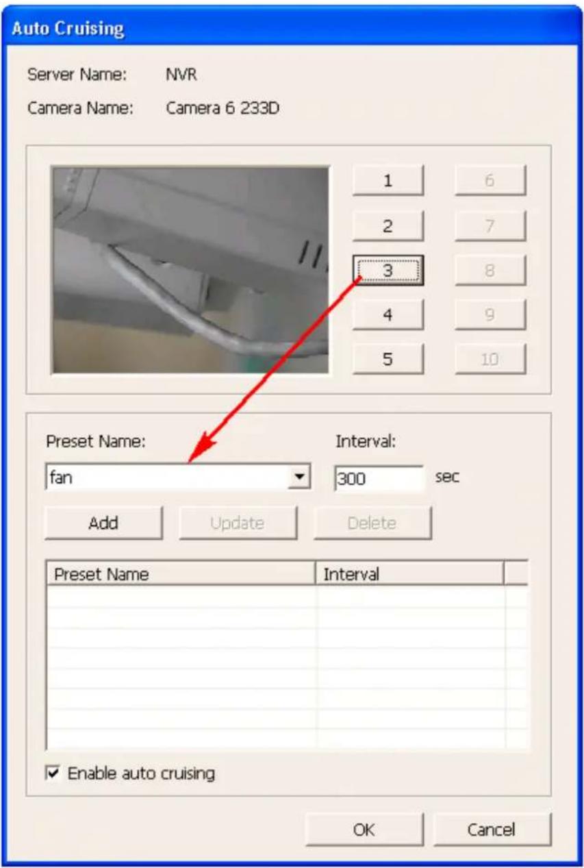
- Add: To add a seng for auto cruising, select the 'Preset Name' from the drop-down menu and enter the staying me (interval, in seconds). Click 'Add'.
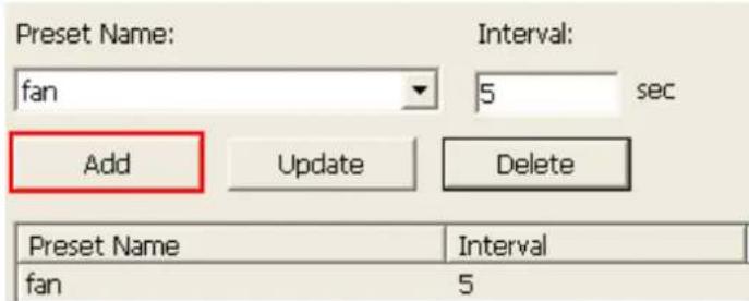
- Update: To change a seng on the list, highlight the selecon. Select another preset posion from the drop-down menu and/or change the staying me (interval). Click 'Update'.
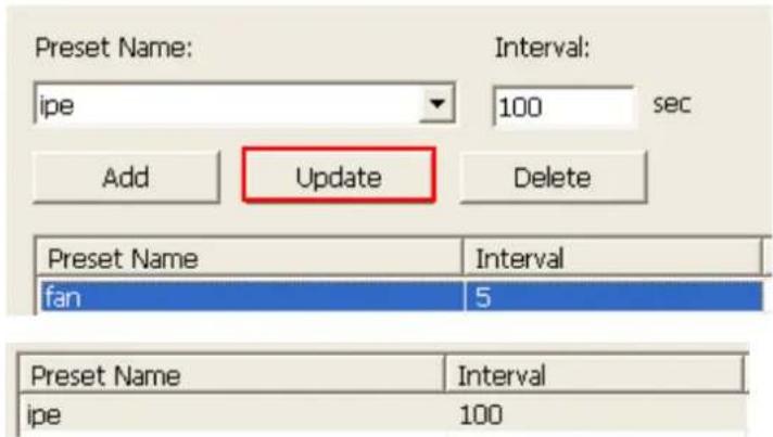
- Delete: To delete a setng, highlight a selecon on the list and click 'Delete'. To delete more than one seng, press and hold the Ctrl key and select the sengs. Then click 'Delete'.
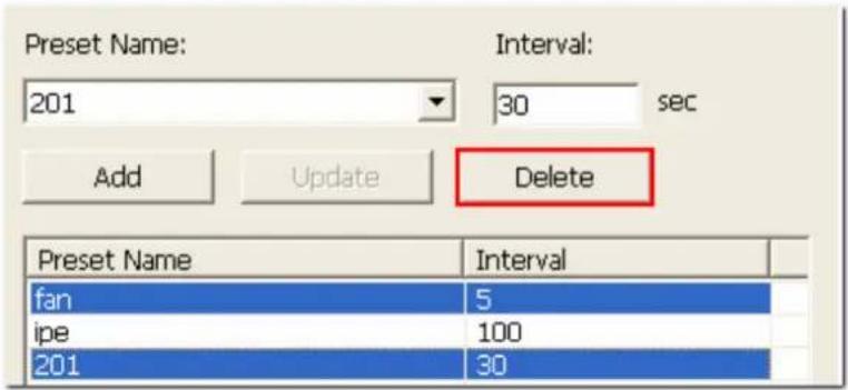
- Aer conguring the auto cruising sengs, select the opon 'Enable auto cruising' and click 'OK'. The NVR will start auto cruising according to the sengs.
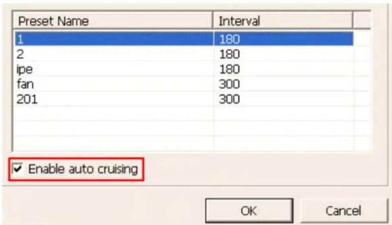
- Auto cruising supports 'snapshot'
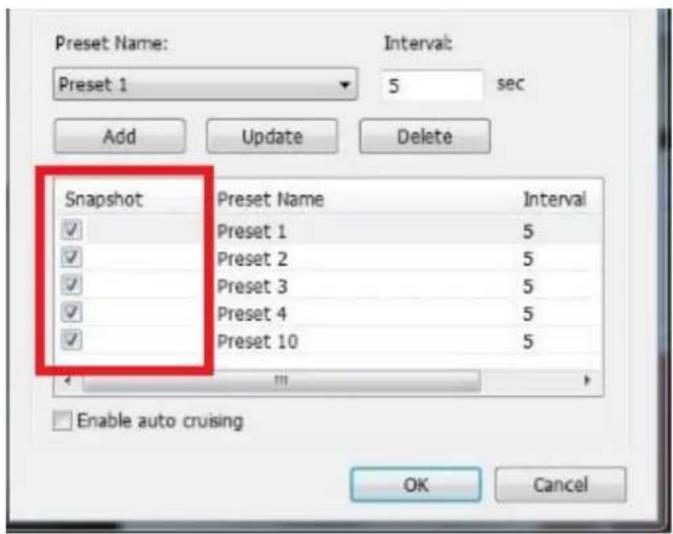
Note:
- The default staying me (interval) of the preset posion is 5 seconds. Enter 5 – 999 seconds for this seng.
- The system supports up to 10 preset posions (the rst 10) congured on the PTZ cameras. Up to 20 sengs for auto cruising can be congured. In other words, the NVR supports maximum 10 selecons on the drop-down menu and 20 sengs on the auto cruising list.
5.1.9 Qdewarp
Fisheye cameras are widely used to monitor larger areas. QNAP Qdewarp allows sheye cameras to use their full features. You only need to conjure the sheye camera's installaon locaon (ceiling, wall, or desk), then you can start using mulple QNAP Qdewarp modes. Qdewarp is supported in the monitor and playback page.
Qdewarp mode descripon
| Icon | Funcon | Descripon |
 | 103R | Provides the original screen, and 3 regional screens |
 | 108R | Provides the original screen in the central grid, and 8 regional screens around the center |
 | 1P2R | Providing 2 regional screens in the upper side, and one panorama screen in the down side |
 | 1P3R | Providing 3 regional screens in the upper side, and one panorama screen in the down side |
 | 1P6R | Providing 3 regional screens in the upper side and down side respectively, and one panorama screen in the center = |
 | 4R | Providing 4 regional screens = |
 | 9R | Providing 9 regional screens = |
 | DualPanorama | Providing 2 panorama screens |
 | FullPanorama | Providing one panorama screen |
 | ORP | Providing one original screen one regional screen, and one panorama screen |
 | R | Providing one regional screen |
Note: Only some dewarping modes are supported on local display.
5.1.10 ROI (Region of Interest)
ROI monitoring mode provides 2 monitoring layouts. You can choose a 5 or 7 split layout, and select a region of interest for monitoring.
Please follow the below steps to conjure the ROI.

- Click
on the monitoring page, select

or , then the system
will automacally go into the ROI monitoring mode.
-
You can select the ROI on the camera's eld of view. The system will automatically show the ROI(s) on the side grid. You can also use the mouse to select the ROI, and drag it to change its locaon or adjust the ROI's border to alter its size.
-
Remove the ROI by clicking on

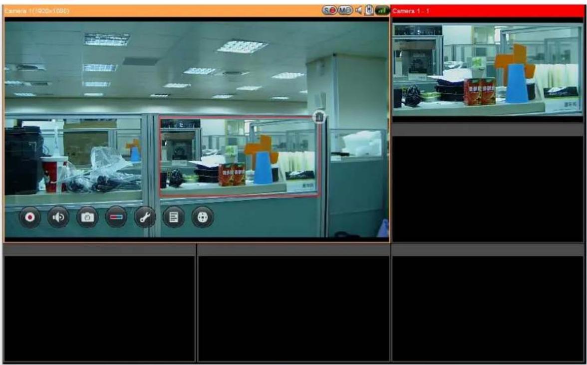
The E-map feature of the NVR is provided to for users to upload electronic maps to the system to indicate the locaons of the IP cameras. Users can drag and drop the camera icons* to the E-map and enable event alert to receive instant nocaaon when an event occurs to the IP camera.
*The camera icons are available only when the IP cameras have been congured on the NVR.
To use the E-map feature, login the monitoring page of the NVR as an administrator
and click

An E-map example is shown below. The NVR provides a default E-map.
Administrators can add or remove the E-maps whenever necessary.
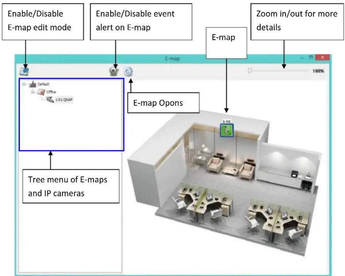
flowchart
graph TD
    A["Enable/Disable E-map edit mode"] --> B["Default"]
    C["Enable/Disable event alert on E-map"] --> B
    D["Zoom in/out for more details"] --> E["E-map"]
    F["Tree menu of E-maps and IP cameras"] --> B
    G["E-map Opons"] --> H["1-01"]
    H --> I["Room 1"]
5.2.1 Icons and Description
| Icon | Descripon |
 | Enable E-map edit mode. |
 | E-map edit mode in use. Click this icon to disable the edit mode. |
 | Add an E-map. |
 | Edit the name of an E-map. |
 | Remove a map or a camera icon. |
 | Event alert not in use. Click this icon to enable event alerts on the E-map. |
 | Event alert in use. When an event occurs on an IP camera, such as a moving object being detected, the camera icon will change and ash to alert the administrator. To disable event alerts on the E-map, click this icon.Note:When event alerts are enabled, the E-map cannot be edited. The icon will become invisible. |
 | E-map Opons. Click on this icon to change the “Icon Size” or “Double-click” on camera icon acon. |
 | Use this control bar to zoom in/out and see more details of E-map. |
 | Icon for a set of E-maps. |
| [326D] | Icon for a single E-map. |
 | Icon for a PTZ IP camera. |
 | Icon for a xed body or xed dome IP camera. Aer dragging the icon to a map, right click on the camera icon to change the icon direcon or delete the icon from the E-map. |
5.2.2 Add a Map Set or an E-map
To add a map set or an E-map to indicate the locaons of the IP cameras, click to enable Edit mode.

A list of IP cameras congured on the NVR will be shown on the le. Click 'Default'
and then to add an E-map.
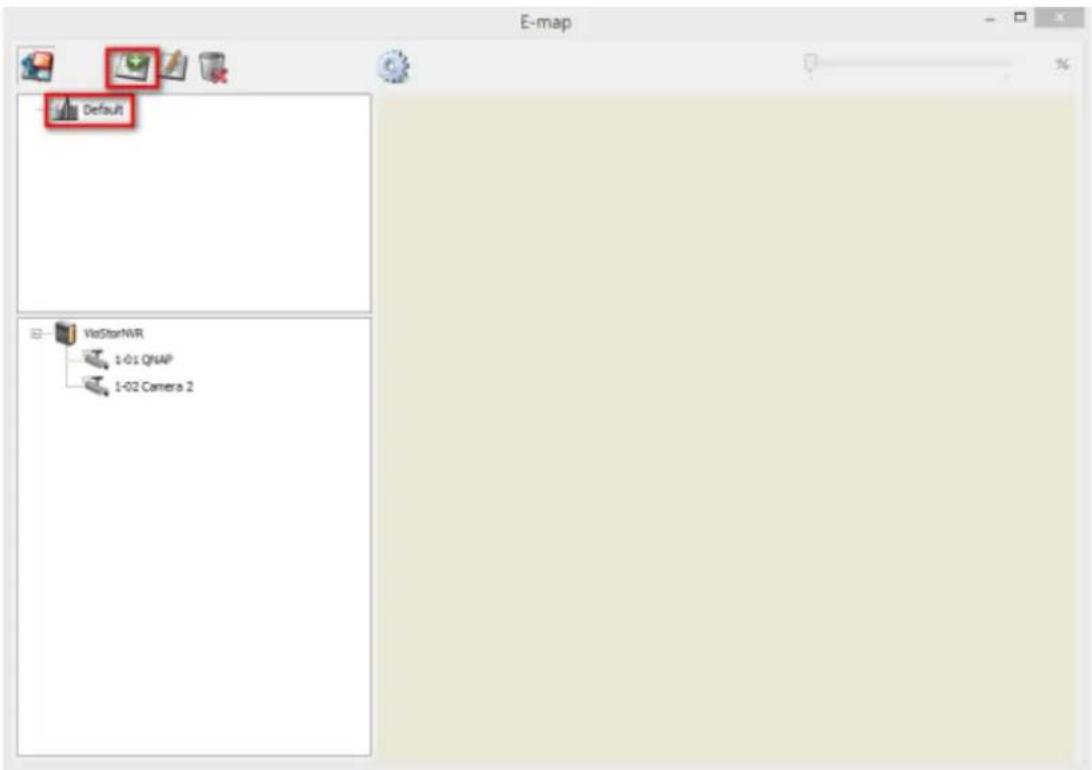
Enter the map name and select the le. The E-map image must be a JPEG format le. Click 'OK'.
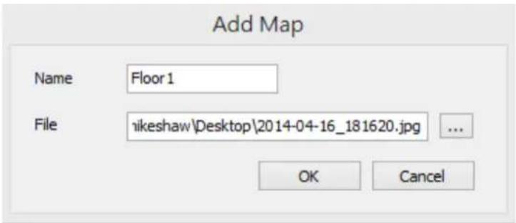
The E-map will be shown.
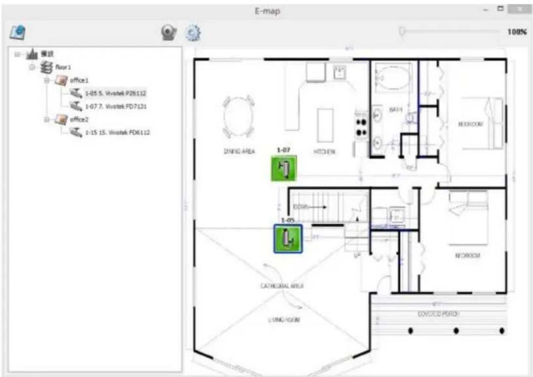
To add one or mulple E-maps, e.g. oce1 and oce2, under an E-map, e.g. oor1,
click the E-map icon of oor1 and then click to add the E-maps one by one.

The icon of oor1 will be changed to when more than one E-map is added. To add another E-map of the same level of oor1, select 'Default' and add the E-map, e.g. oor2.
To zoom in or zoom out the E-map, you can use your mouse wheel or just change the percentage bar in upper le to enlarge or reduce the view of the E-map.
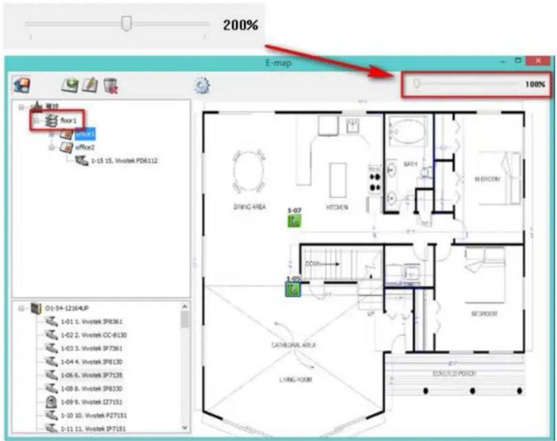
5.2.3 Edit a Map Name
To edit the name of an E-map, select the E-map and click . Enter the new name and click 'OK'. To change the picture of the E-map, delete the E-map and add the new le.
5.2.4 Delete a Map Set or an E-map
To delete an E-map, select the map and click. To delete a set of maps under the same level, select the map set and click.
5.2.5 Indicate IP Cameras on an E-map
Aer uploading the E-maps, drag and drop the IP camera icons to the E-map(s) to indicate the camera locaon. The camera name will appear under the E-map on
the top le column. When an icon of a xed body or xed dome IP camera is dropped to the E-map, right click the camera icon and adjust the icon direcon. The icon of a PTZ IP camera cannot be adjusted. The naming rule of camera is as follows: [Order of Server]-[Order of Channel][Camera Name]. For example : "1-05 Corner" means channel 5 of NVR1 and its camera name is "Corner".

To delete a camera icon from the E-map, right click on the icon and select 'Delete'.
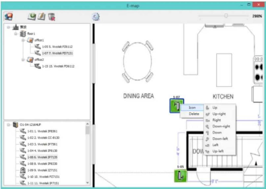
To save the changes made to the E-maps, click to exit Edit mode.
When clicking an E-map or an IP camera on the le, the E-map or the E-map with the camera icon will be shown on the right immediately. The selected camera icon will
be highlighted with a blue bracket And the view of IP camera will be shown in
single-channel mode on the monitoring screen.
You can choose the Double-click acon on the Camera Icon in "Emap Opons" by
clicking

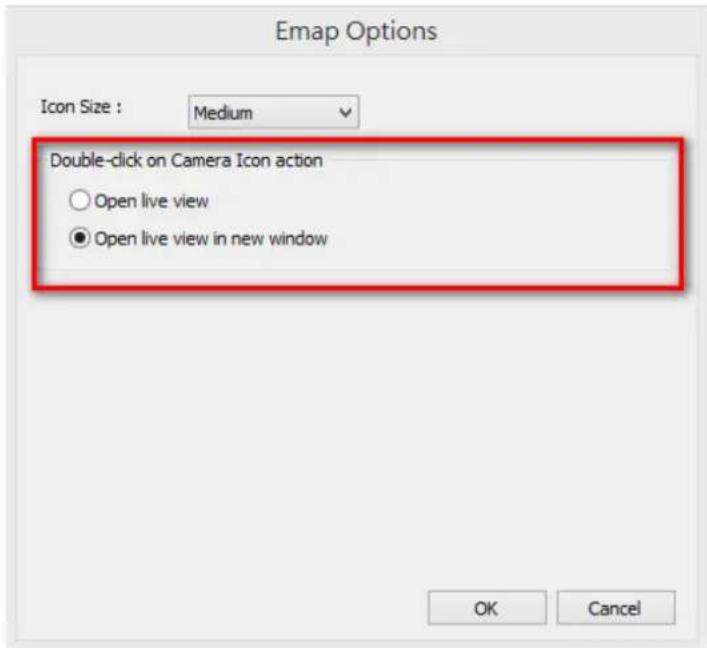
- Open live view: Whether or not Edit mode is enabled, the view of IP camera will be shown in single-channel mode on the monitoring screen.
- Open live view in new window : Whether or not Edit mode is enabled, the view of IP camera will be shown on another window.
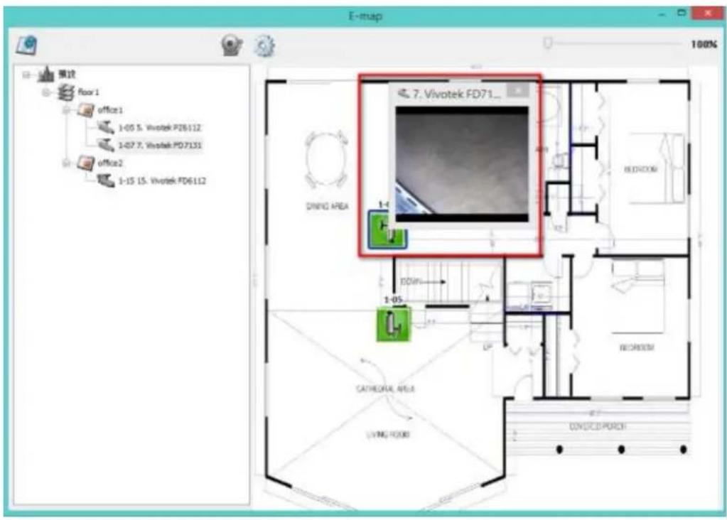
5.2.6 Enable/Disable Event Alert
To enable event alerts on an E-map, click

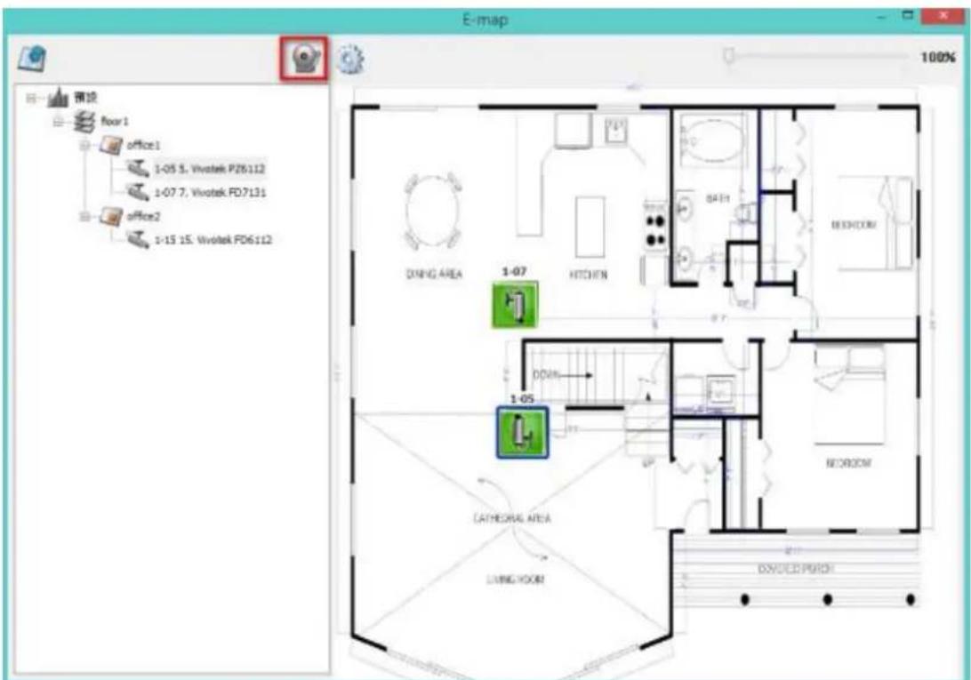
When an event occurs to an IP camera on the E-map, the camera icon will ash and indicate the event type. The E-map with the IP camera on which an event is triggered will be shown immediately*. Double click on the camera/alert icon and the monitor screen will switch to display the alert camera channel in single-channel view on the monitor screen automacally.
*The E-map with event alerts will not be switched to display automacally if the me dierence between the event me and the last me the user uses the E-map (clicks the E-map window) is less than 20 seconds. In this case, refer to the tree menu on the le to locate the IP cameras with alerts/ashing icons.
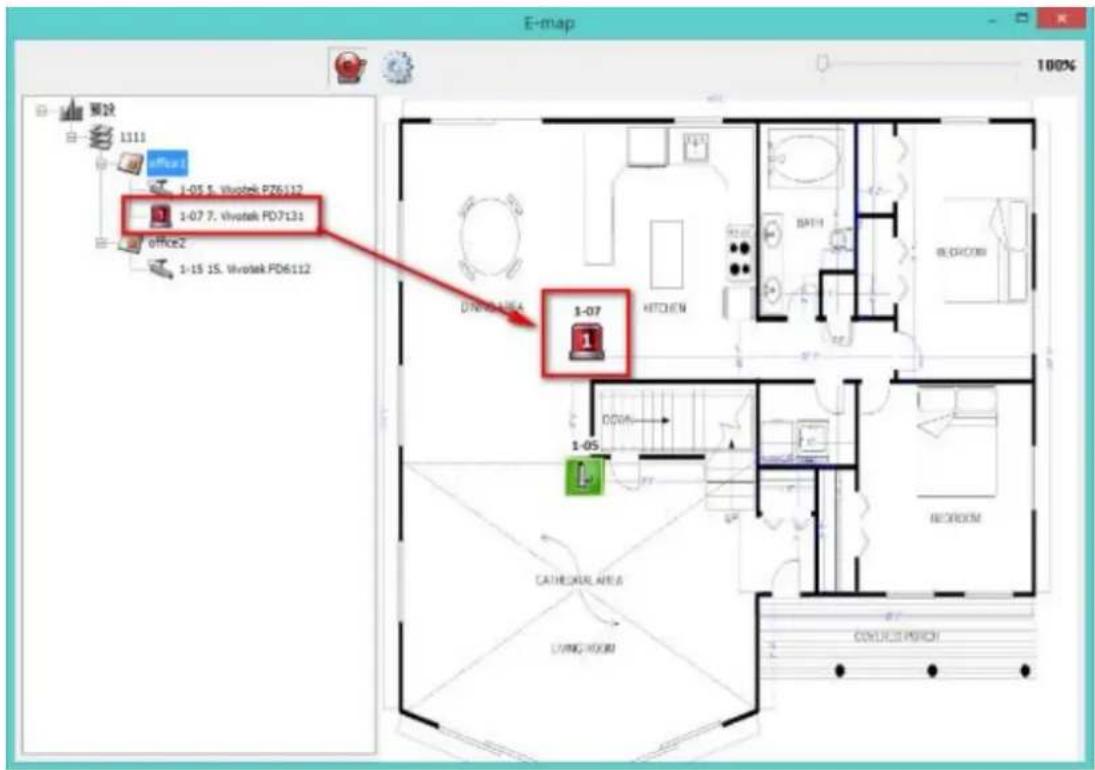
The event type occurring to an IP camera can be idened by the camera icon on an E-map.
| Icon | Descripon |
| A moving object has been detected | |
| The alarm input 1 of the IP camera has been triggered | |
| The alarm input 2 of the IP camera has been triggered | |
| The alarm input 3 of the IP camera has been triggered | |
| An unidened event has been triggered |
5.3 Remote Monitoring from the QNAP QVR Client for
Windows
-
Aer installing the QNAP QVR Client for Windows, click Start → All Programs → QNAP → QVR → Surveillance Client to open the QNAP QVR Client for Windows.
-
The following window will be shown.
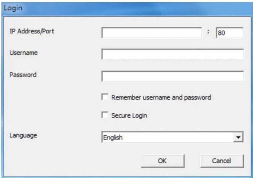
-
Enter the IP address/port, user name and password to login the NVR.
-
All the monitoring funcons of the QNAP QVR Client for Windows are similar to those of the browser-based interface. Please refer to other seconds of this chapter.
Chapter 6. Play Video Files
Use Google Chrome, Mozilla Firefox, or Microso Internet Explorer and the QNAP QVR Client to playback the les recorded by the NVR.
- To play the recording les in Internet Explorer, please add the NVR IP address to the list of trusted sites. When accessing the NVR via Internet Explorer, you will be prompted to install the AcveX add-on.
- To play the recording les by Google Chrome, Mozilla Firefox or QNAP QVR Client on Windows PC, please visit hp://www.qnapsecurity.com/download.asp to download and install the QNAP QVR Client for Windows.
- To play the recording les on Mac, please visit hp://www.qnapsecurity.com/download.asp to download and install the QNAP QVR Client for Mac.
6.1 Playback Page
- Click the playback buon on the monitoring page or the QVR desktop.
- The playback page will be shown. You can search and play the video les on
the NVR servers. To return to the monitoring page, click

To enter the
surveillance sengs page, click


Note: The playback access right to the IP cameras is required to view and play the video les.
The following table consists of the icons and their descripons in the playback page.
| Icons | Descripon |
 | Congure the opons such as playing mode, snapshot sengs, and digital watermark |
 | Mul-view mode (up to 16-view mode) |
 | Control all views: Control the playback sengs of all the playback windows |
 | Convert the video les on the NVR to AVI les |
 | Select the playback video type (alarm recordings, regular recordings, recovery recordings, etc) |
 | Open recording les |
 | Standard bandwidth mode |
| — | |
 | Low bandwidth mode |
 | Take a snapshot of the video |
 | Audio (oponal): Turn on/o the audio support |
 | Search recording les by IVA |
 | Dewarp sheye images:For specie sheye cameras (Note 1) and the specie camera models with panomorph lens (Note 2), you can enable/ disable dewarping funcon. Aer enabling the funcon, you can then select mount type, dewarping mode. |
 | Last me interval |
 | Increase the interval of scales on the meline |
 | Decrease the interval of scales on the meline |
 | Next me interval |
 | Average Time-Divided Playback |
| — | |
 | Digital zoom: Enable/Disable digital zoom. When digital zoom is enabled ( ), you can use your mouse wheel to use digital zoom funcon. zoom is enabled ( ), you can use your mouse wheel to use digital zoom funcon. |
Playback and Speed Control Shule Bar

 | Playback Control Buon: Play/pause recording les |
 | Speed up |
| [KCZY] | Speed down |
| [KB5H] | Last frame |
 | Next frame |
 | Right side of shule bar is normal play, and le side of shule bar is reverse play. When you drag the playback control buon to right, it will play normally. When dragging the playback control buon to le, it will reverse play. When dragging to the center of shule bar, it will pause. |
6.1.1 Play Video Files from NVR
Follow the steps below to play the video les on the remote NVR servers.
- Drag and drop camera(s) from the server/camera tree to the respective playback window(s) to select the channel(s) for playback.

- Select the playback date from me interval. You can examine each channel to know the me range when the les are recorded for each IP camera. The blue cells indicate regular recording les and the red cells indicate alarm recording les. If it is blank in the me period, it means no les are recorded at that moment.

-
Click to start playback, or click on a channel screen.
-
Specify the me to play back the recording les at that moment.
-
Click to control all the playback windows to play back the recording les.
When this funcon is enabled, the playback opons (play, pause, stop, previous/next frame, previous/next le, speed adjustment) will be applied to all the playback windows.
Note
- Applied to speci sheye cameras: please refer to the below camera compatibility list hp://nvr.qnapsecurity.com/n/en/product_z_g_qvr/cat_intro.php?hf=old Aer enabling the feature, you can select Mount type, including wall, ceiling,
and oor and then select Dewarping mode, including Panorama (Full View), Panorama (Dual View), and Rectangle.
Remark 1: If the Mount type is Wall, only Panorama (Full View), and Rectangle are supported in Dewarping mode.
Remark 2: If Dewarping mode is Rectangle, you can use PTZ control panel to operate PTZ funcons, excluding digital zoom.
- Applied to the specific camera models with panomorph lens.
Before using this feature, you need to select the 'Enable panomorph support' opon in the camera conguraon page. Right click the channel and enable the feature. Aer that, you can select Mount type, including wall, ceiling, and oor and then select Dewarping mode, including Perimeter mode, Quad mode, and PTZ mode.
Remark 1: To know the camera models which can be installed with panomorph lens, please visit
hp://www.qnapsecurity.com/n/en/qa/con_show.php?op=showone&cid=128.
Remark 2: The funcon is only available when the resoluon of the video stream is higher than 640x480 on the monitoring page.
Remark 3: If Dewarping mode is PTZ mode, for the channel, you can use PTZ control panel or mouse (by clicking and holding down the mouse le buon, and then moving the mouse or turning the mouse wheel) to change viewing angles or zooming in/out the screen. If Dewarping mode is Quad mode, the above methods can also be applied to operate PTZ funcons in each divided screen.
6.1.2 Intelligent Video Analytics (IVA)
The NVR supports intelligent video analytics for video data search.
The following features are supported:
● Moon detecon: Detects the movements of the objects in the video.
● Foreign object: Detects new objects in the video.
● Missing object: Detects missing objects in the video.
● Out of focus: Detects if the camera is out of focus.
● Camera occlusion: Detects if the IP camera is obstructed.
To use this funcon, follow the steps below:

- Enter the playback page. Select one channel and click .
Note: The intelligent video analytics support video search on one IP camera channel only.
- Select recording type, start me and end me for video search.
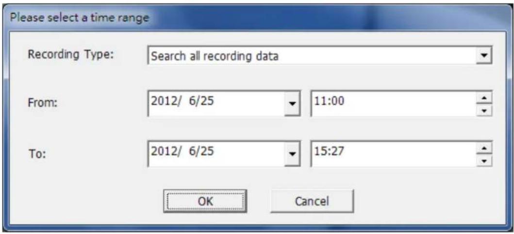
- Congure the IVA sengs for video search.

A. Select the detecon mode: Moon detecon, Foreign object, Missing object, Out of focus, or Camera occlusion. Mulple opons can be selected.
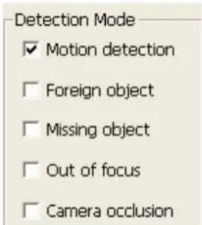
B. Adjust the sensitivity for object detecon.

C. Adjust the me interval for detectng the foreign objects and missing objects. If a foreign object appears or a missing object disappears for a period of me which is longer than the me interval, the NVR will record the event.
Note: The Interval slide bar appears only when 'Foreign object' or 'Missing object' is selected.
D. Dene the detecon zone. Mouse over the edge of the red zone and use the mouse to dene the detecon zone. Click 'Select all' to highlight the enre area.
E. Dene the object size for detecon. Use the mouse to drag the yellow zone to dene the minimum object size for detecon.
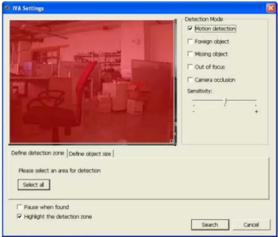
- Ignore objects with width or height less than this seng: Enable this opon to ignore all the objects smaller than the yellow zone.
F. Enable/Disable other opons for video search.
- Pause when found: Enable this opon and the video search will stop when a video le matching the search criteria is found.
-
Highlight the detecon zone: The moving objects detected in the video will be highlighted in red boxes; the foreign or missing objects will be highlighted in yellow boxes; the video which is out of focus or obstructed will be displayed in transparent red.
-
Click 'Search' to start searching the video by IVA. The results will be shown.
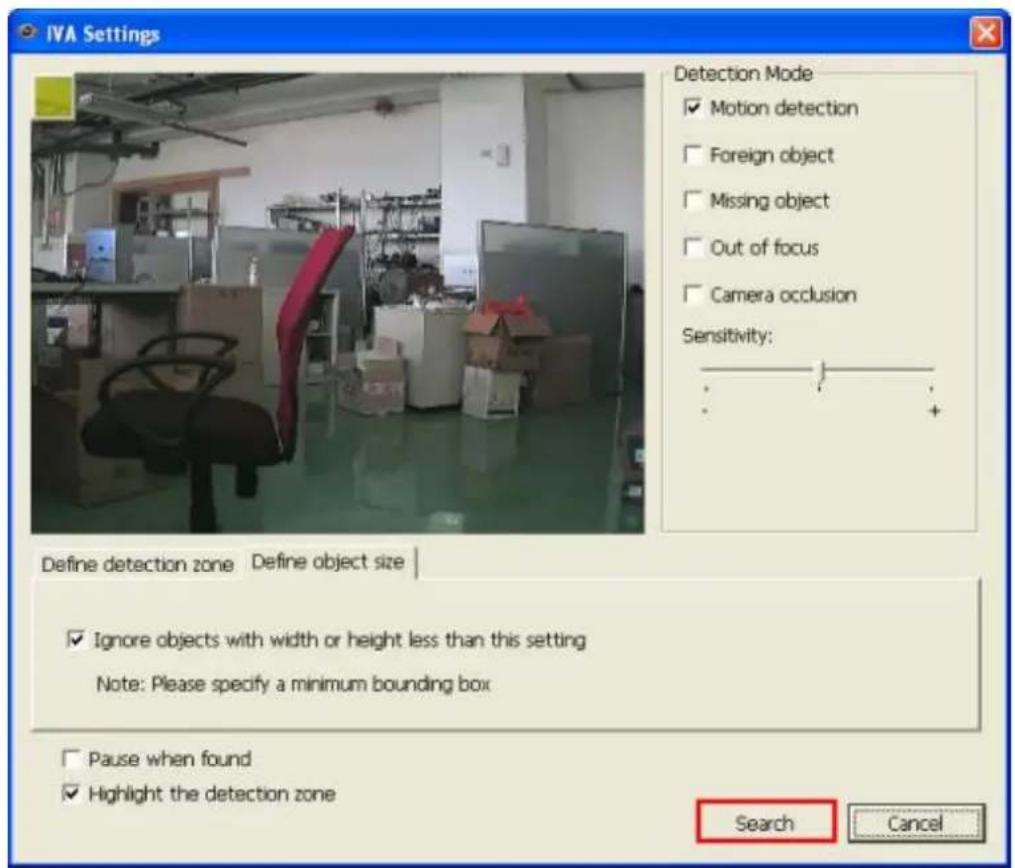
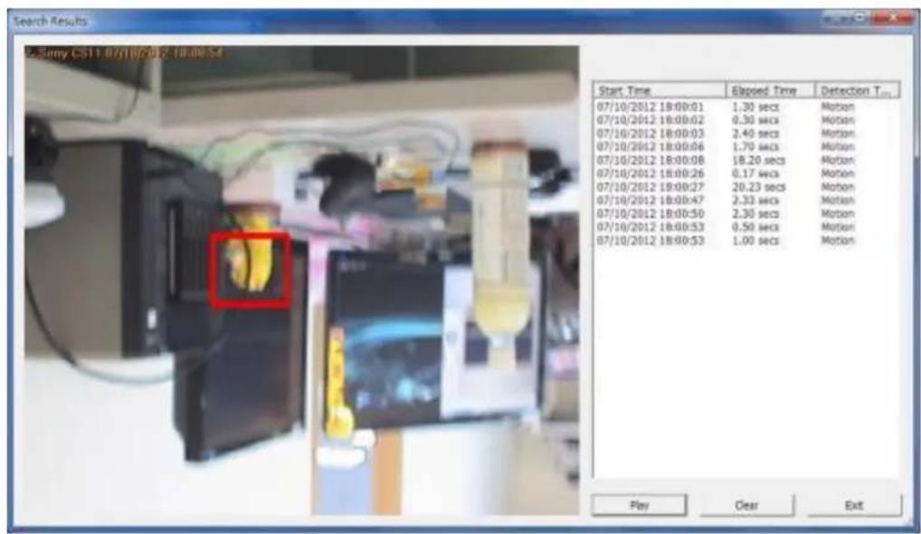
Other opons:
- Double click an entry on the search result dialog to play the video. The player will play the video starng from 15 seconds before the event to 15 seconds aer the event.
● Right click an entry on the search result dialog to export the video (AVI format)
and save it to the computer. The exported video starts from 15 seconds before the event to 15 seconds aer the event.
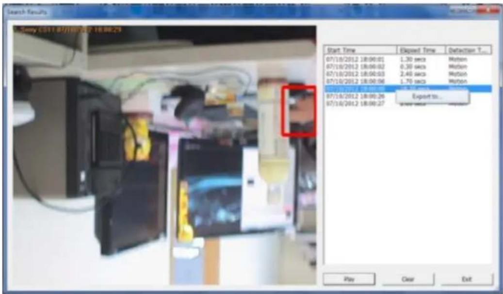
6.1.3 Export NVR Videos
To convert the video les on the NVR and export the le, please follow the steps below.
-
Select an IP camera and click 📋 to 'Convert to AVI le'.
-
Select recording type, start me and end me for video exporng.
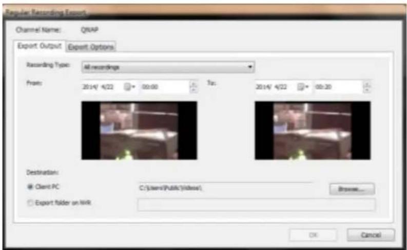
A. Choose the recording type.

B. Specify the me range. Specify a smaller me range, or the video le will be too large and take a long me to convert.

-
You can specify the locaon where the le will be saved on client PC or to the NVR.
-
Enter the le name.
-
You can modify the export opons.
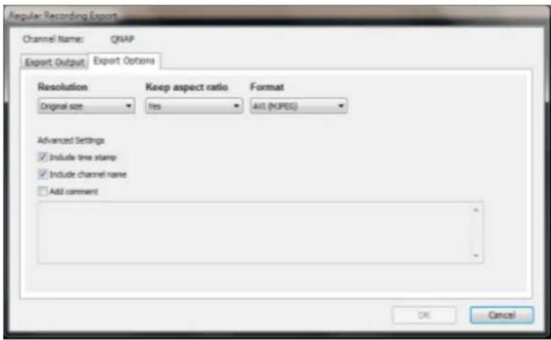
A. Choose the exporng resoluon.
B. Select to keep the aspect rao of exported le or not.

C. Select the le format (video compression) of the exported le.

D. You can select to include a me stamp and the channel name in the exported le or to add comments (will have one more txt le saved as same le name in the same folder).
-
Click 'OK'.
-
All the video les that meet the search criteria will be converted.
6.1.4 Export Video Files with Digital Watermark
The NVR supports digital watermarking to protect the videos and snapshots from unauthorized modicaons. Digital watermarks can be added to the exported videos and snapshots in the playback page. The watermark cannot be removed and can only be verified by the QNAP Watermark Proof soware.
To use digital watermarking in the playback page, follow the steps below.
-
Enter the playback page.
-
Select to add digital watermarks in the exported snapshots or videos.

- Click ‘Convert to AVI le’ (refer to Chapter 6.1.3). Digital watermarks will be added to the exported video les and snapshots.
6.1.5 Enable Recording Video Files
Please follow the below steps to enable recording video les in the playback page.
- Click to enable AVI les
- Select the video iles and start playback
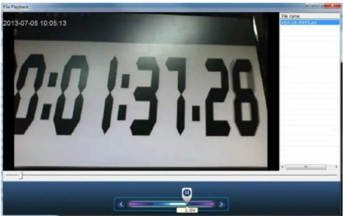
6.1.6 Average Time-Divided Playback
Click to designate a channel for Average Time-Divided Playback. This can be divided for 4 channel or 9 channel display mode.
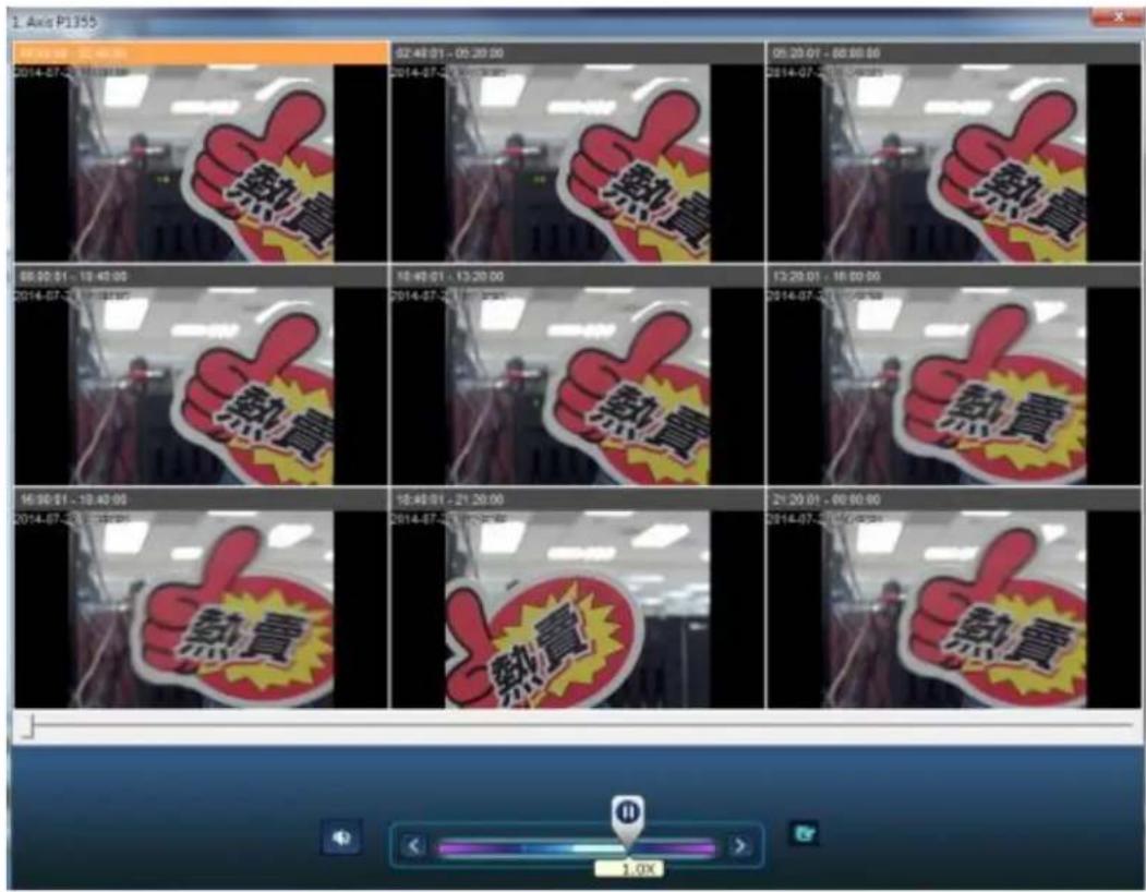
6.2 Play Video Files in the QNAP QVR Client for Windows
- Click Start → All Programs → QNAP → QVR Client → Surveillance Client to open the QNAP QVR Client for Windows.
- The following window will be shown.
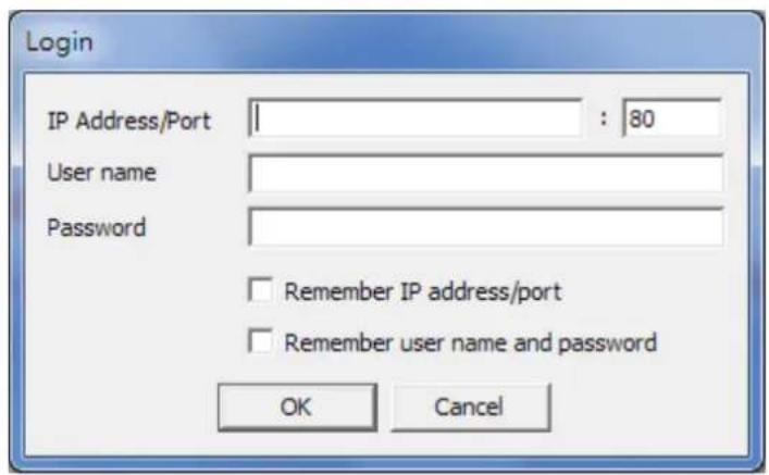
- Enter IP address/port, user name and password to log into the NVR.
- All the playback funcons of the QNAP QVR Client for Windows are similar to those of the browser-based interface. Please refer to other seconds of this chapter.
6.3 Watermark Proof
The Watermark Proof utility is installed automacally along with the QNAP QVR Client for Windows. From the Windows Start menu, select 'All Programs' > 'QNAP' > 'QVR Client' to locate 'Watermark Proof'.
Run Watermark Proof. The following window will be shown.
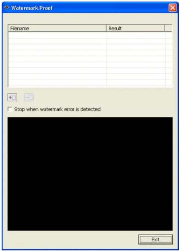
Click to browse and locate the les. Mulple les can be selected at one me.
Click to check the les and view the proof result. When 'Stop when watermark error is detected' is selected, the checking process will stop if a failed le is detected. Otherwise the program will check all the les selected. If a video le
has been modified, or is not exported with digital watermark, or not an NVR video le, the proof result will be shown as 'Failed'.
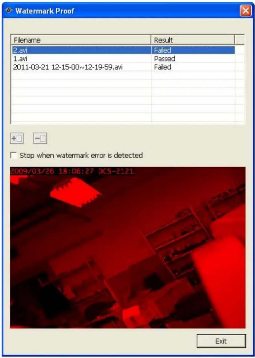
6.4 Access the Recording Data
The recording data on the NVR can be accessed by the following services:
● Microso Networking (SMB/CIFS)
- FTP Server (FTP)
Note:
- To access the video les by these protocols, enter the user name and password with the administrator access right.
6.4.1 Microsoft Networking (SMB/CIFS)
Access the video les by the SMB/CIFS protocol on Windows OS.
- Run \NVR_IP from the Windows Start menu. For example, if the NVR IP is 10.11.19.27, enter \10.11.19.27.
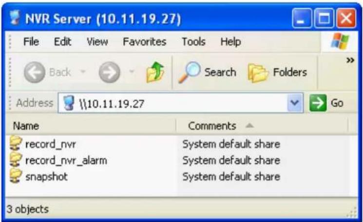
6.4.2 FTP Server (FTP)
Access the recording data by FTP:
- In Google Chrome, Mozilla Firefox, or Microso Internet Explorer, enter p://username:password@NVRIP. For example, enter p://admin:admin@172.17.26.154 if the NVR IP is 172.17.26.154.
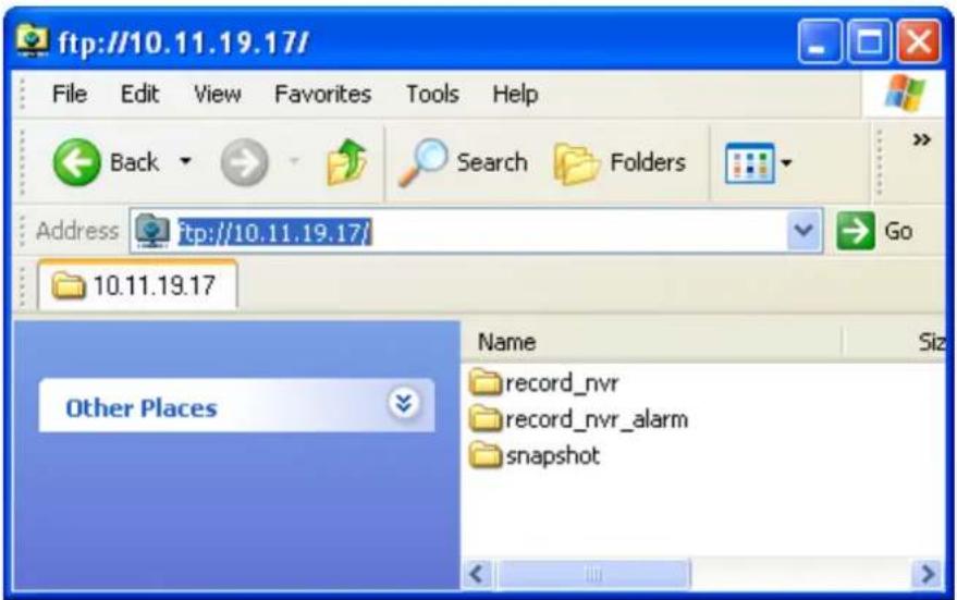
Note: You cannot play recording les via double click here.
Chapter 7. Surveillance Settings
To enter the surveillance sengs page of the NVR, login to the monitoring page as an
administrator and click

7.1 Camera Settings
7.1.1 Camera Overview
You can view a camera preview and more informaon, including the camera name, IP address, conncon status, recording seng, days recorded, recording le size, free disk space, CPU usage and internet bandwidth.
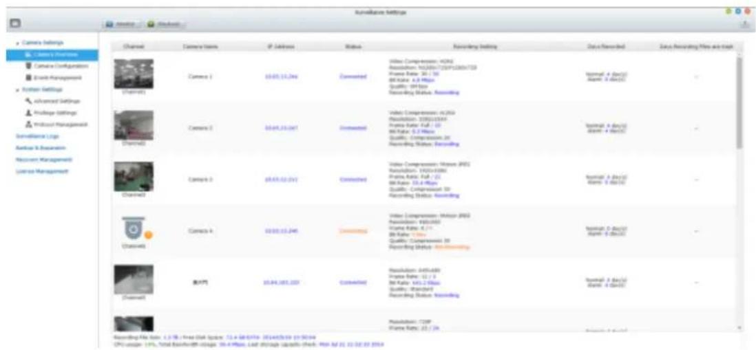
7.1.2 Camera Configuration
You can add/edit a camera's conguraon, export/import a camera's conguration, modify recording sengs, and scheduled recording sengs.
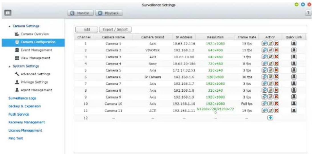
Please follow these steps to add a new camera.
- Click to add a camera.
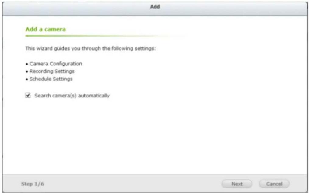
- 'Search camera(s) automacally' is enabled by default.
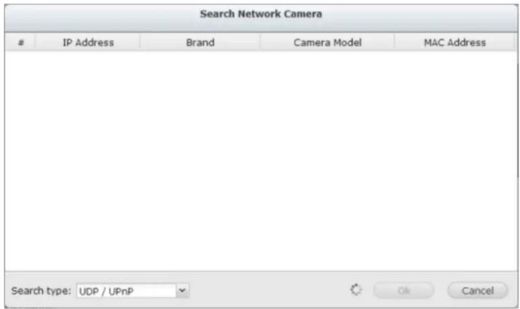
You can select the search type: UDP/UPnP or ONVIF.
- You can also cancel this search and manually add the camera.
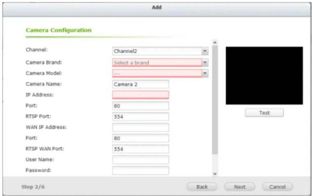
Select the camera brand, model, name, IP address or domain name of the camera and the user name and the password to login to the camera. And select whether or not to enable the recording.
The NVR provides an interface for the users to enter the JPEG CGI command of the IP cameras in order to receive the video and audio streaming data from the IP cameras and monitor, record, and playback the video of the IP cameras on the NVR. Please refer to Note 1 for more informaon.
- Click 'Next' for recording sengs.
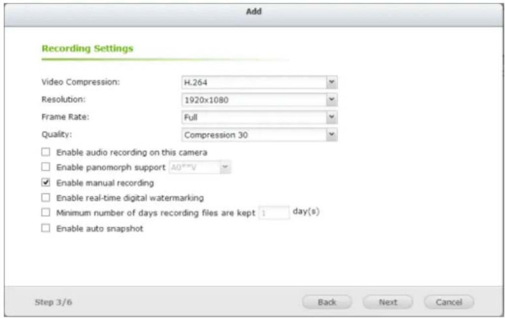
Congure the video compression, recording resoluon, frame rate, and quality. Enable audio recording, manual recording, recording data retenon, real-me digital watermarking, and auto snapshot sengs. For further informaon regarding cameras that support “User dened Mul-stream” and “Smart Recording”, please refer to the list described in that secon.
A. Mul Stream: You can set the conguraon of every stream.
B. Video compression: Choose a video compression format for the recording.
C. Resoluon: Select the recording resoluon.
D. Frame rate: Adjust the frame rate for the recording. Note that the frame rate of the IP camera may be aected by network trac.
E. Quality: Select the image quality for the recording. More disk space is required to save higher quality recordings.
F. Quality Preview:
Click 'Quality Preview' to get a preview of how your videos will look.
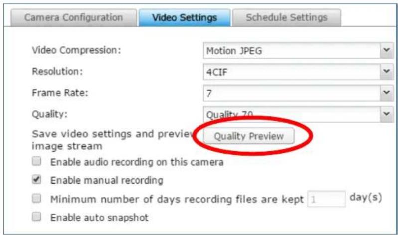
You can set video compression, resoluon, frame rate and quality and see a preview picture by clicking 'Preview'.
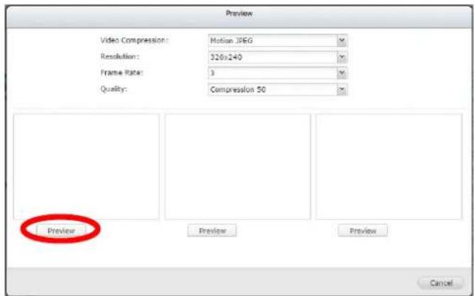
You can click the magnier buon to get a larger and clearer preview.
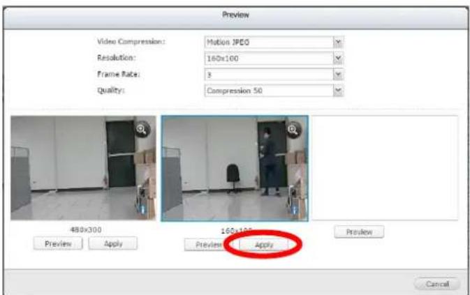
When you are happy with your sengs, click 'Apply' to enable these camera sengs.
G. Audio recording (oponal): To enable the audio recording, click 'Enable audio recording on this camera'.
H. Enable panomorph support: For the specic camera models with panomorph lens, you can enable this opon.
Note: To know the camera models which can be installed with panomorph lens, please visit hp://www.gnapsecurity.com/faq_detail.asp?faq_id=718.
- Manual recording: To allow manual acvaon and deacvaon of manual recording funcon on the monitoring page, enable this opon.
J. Real-me digital watermarking: Enable this opon to add digital watermarks to the video les as soon as they are recorded to the NVR. Use the Watermark Proof ulity to verify if the video les were maliciously modified.
K. Enable recording data retenon: Turn on this funcon and specify the minimum number of days to keep the recording data. Note that the number of days entered here must be smaller than the maximum number of days to keep all recordings congured in 'System Sengs' > 'Advanced Sengs'.
L. Enable auto snapshot: Select this opon and the sengs will be displayed. Congure up to 15 schedules for automac snapshot taking or specify the number of snapshots (max 60) the NVR should take every hour. The snapshots are saved to the share folder of the NVR by default. Specify a remote server to where the les will be saved. Read/write access to the remote server is required.
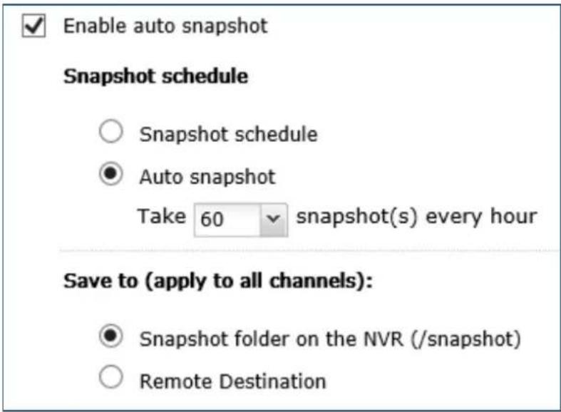
M. Edge Recording: When Edge Recording is enabled on VioStor NVR, the camera can save the recording les on its local storage (such as a SD card) even when the conncon to the NVR suddenly becomes unavailable. Aer the conncon is resumed, the NVR will check its recording les and compare the recording schedule set by users. If the NVR detects that recording les are missing, it will request the camera to upload the missing part.
- Click 'Next' for schedule sengs.
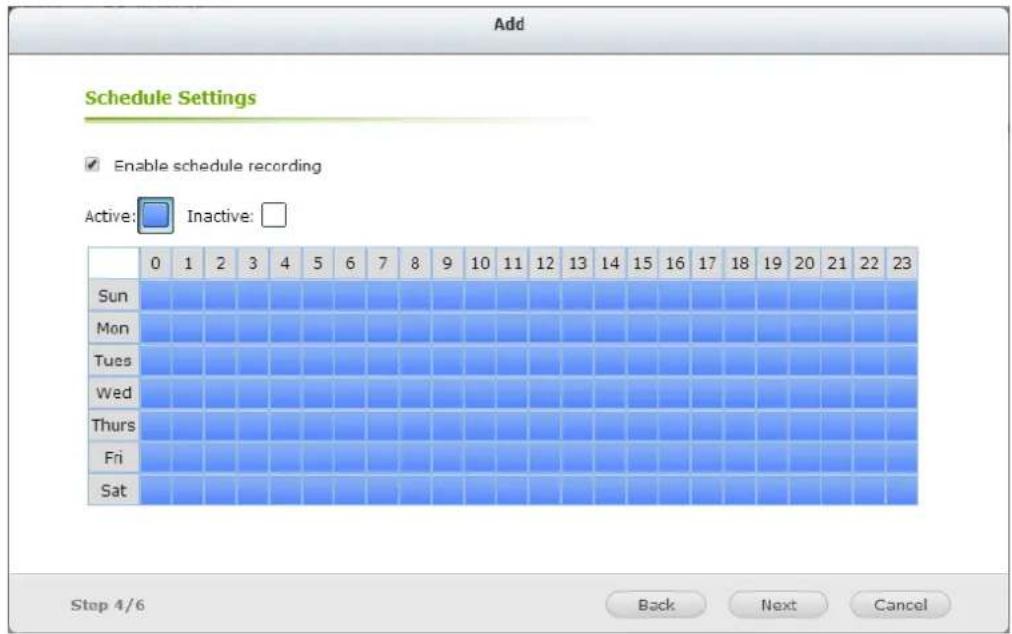
Click and drag on the schedule table to enable scheduled recording for that period of me. Click and drag on the schedule table to disable
schedule recording for that period of me.
Note:
- Starng and stopping manual recording will not affect scheduled or alarm recording tasks. They are independent processes.
- When applying the changes, the recording operaon will be temporarily paused (maximum 1 minute) and then restart.
- The sengs of the snapshot folder are global seings which will be applied to every channel.
You can then click to edit the camera sengs.
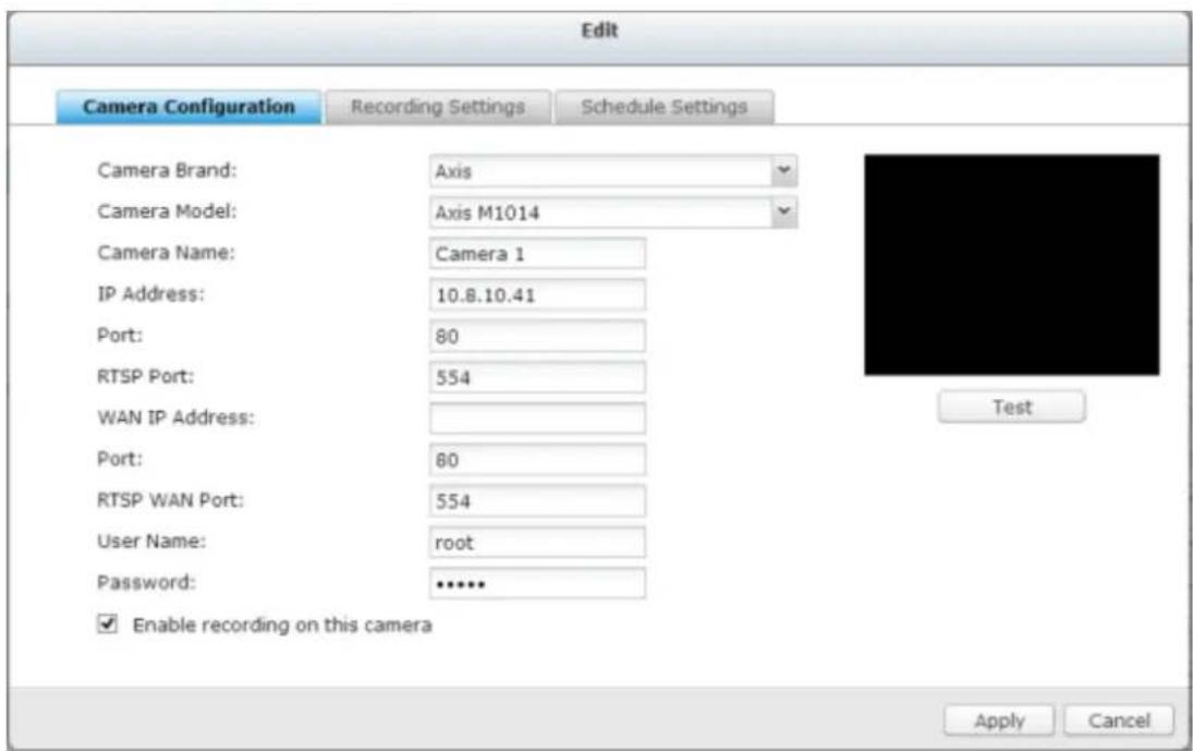
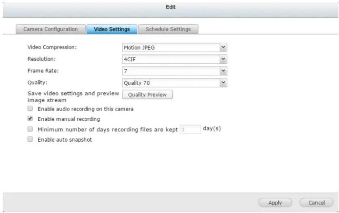
Click Apply to apply the sengs.
Note:
- All the sengs will not take eect unl 'Apply' is clicked. When applying the changes, the recording operaon will temporarily stop (for a maximum of one minute) and then restart.
Export / Import camera sengs
This helps you backup and replicate camera sengs to another NVR (it must be the same model).
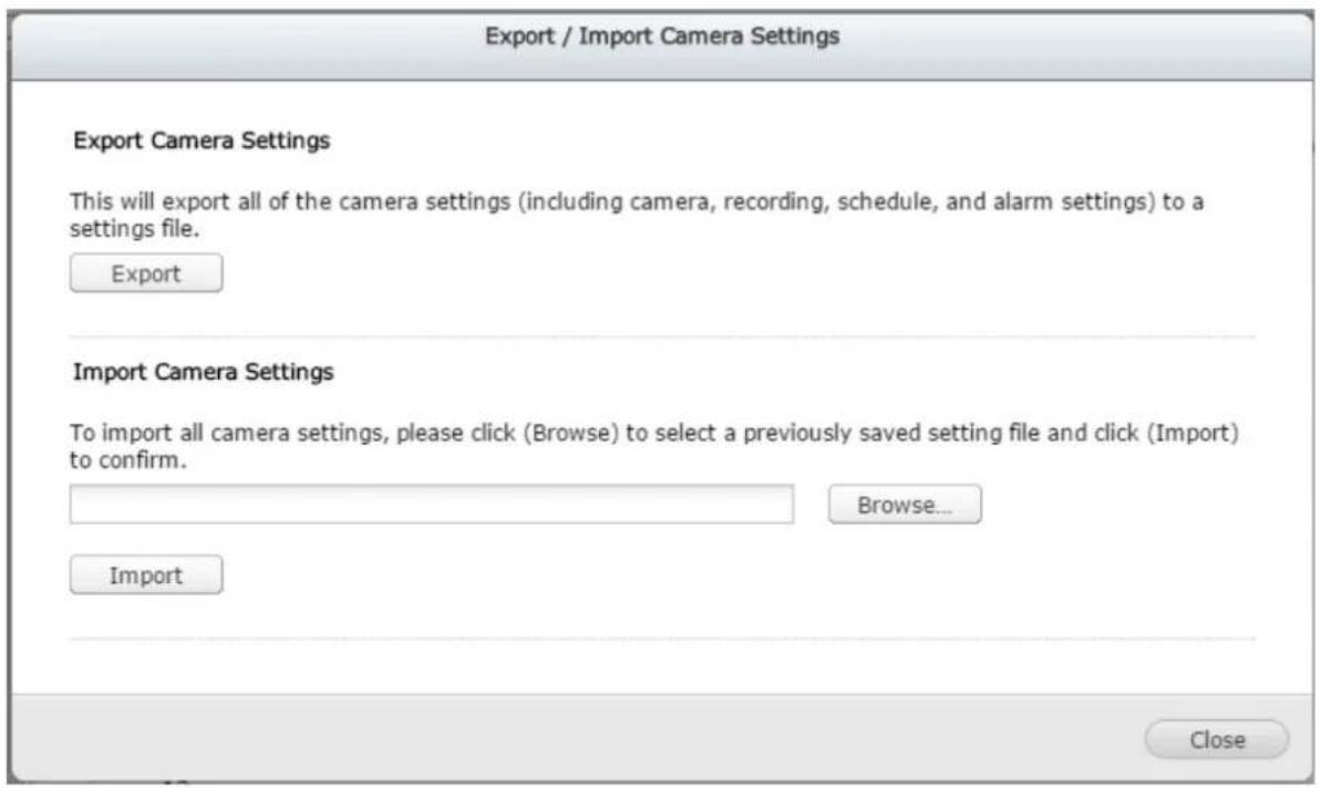
The export le name rule is: Surveillance_qvrOnlyBackup_[date].bin

Surveillance_qvrOn....bin
Add generic IP camera support with a CGI command
Follow the steps below to congregate the IP camera:
- Select 'Generic Model' for the camera brand.
- Select 'Generic JPEG' for the camera model.
- Enter the CGI path of the IP camera in the 'HTTP URL' eld.
- Enter the camera name or the IP address of the camera.
- Enter the user name and the password of the IP camera.
- Select to enable the recording or not.
Note: The NVR only supports JPEG CGI command interface, but does not guarantee the compatibility with all the IP camera brands.
Virtual Camera
The era of high-megapixel cameras has come. It not only means clearer and higher-quality videos, but also a larger coverage area for cameras. You can select an area of a camera's eld of view as a virtual camera, and also view physical and virtual cameras from the view management page for easier monitoring.
To add a virtual camera: click aer adding a physical camera.
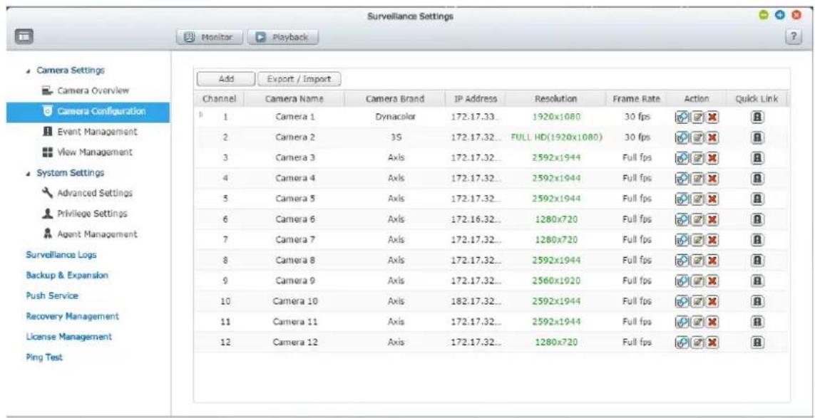
Congure virtual camera
- Virtual camera name: enter a name for the virtual camera.
- Virtual camera index: the virtual camera's number under a physical camera
- Virtual camera area: you can edit the virtual camera's area and its size by dragging the area on the "Edit Virtual Camera Area" window, or by entering values for its area and size.
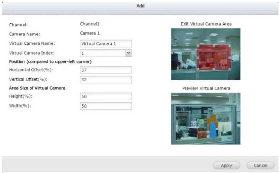
Virtual camera's applicaon
- In the view management page, you can add a virtual camera to a view.
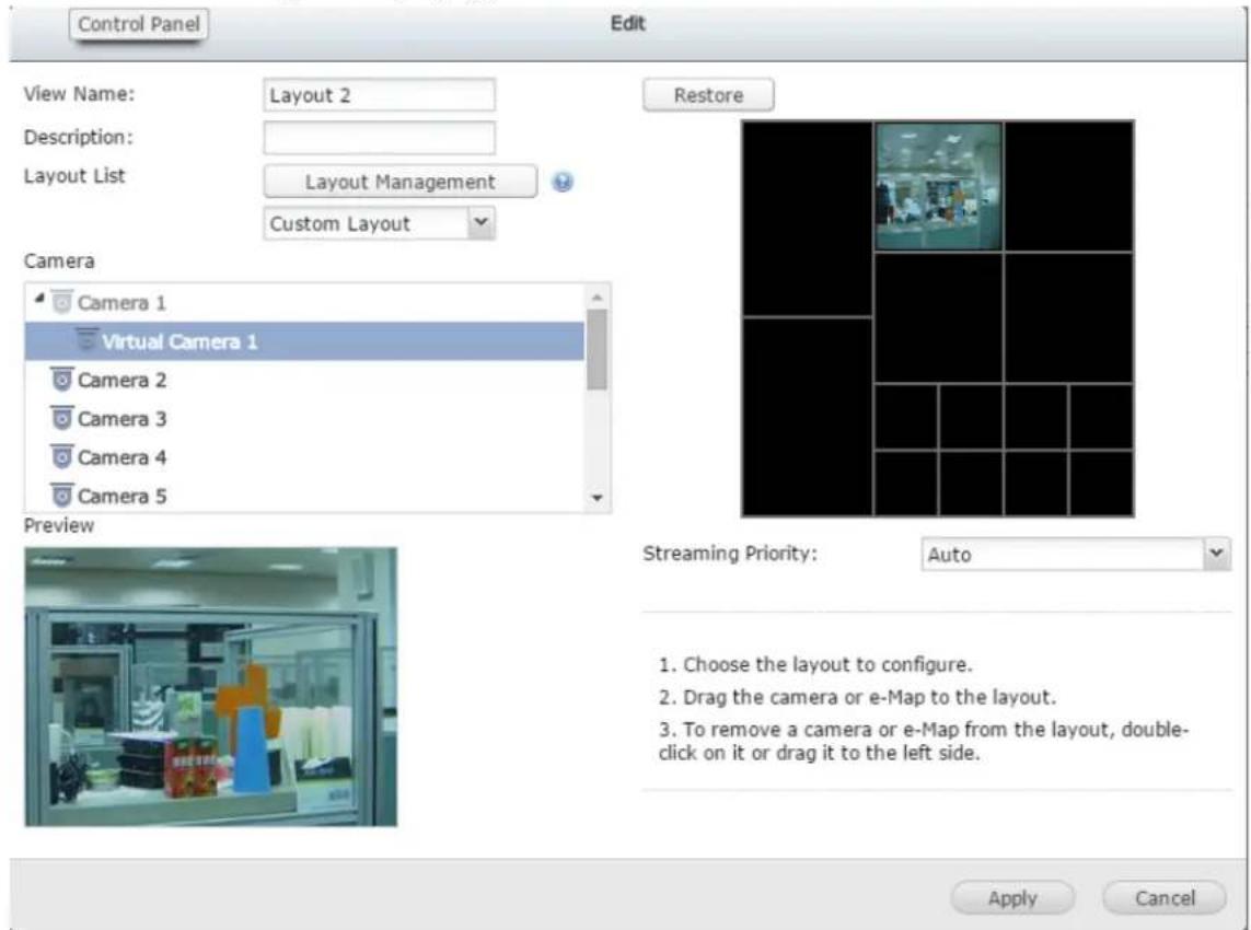
- In the monitor page, you can drag virtual cameras into any window to monitor it.
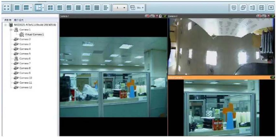
User Deined Multi-stream
In the past, users of digital surveillance systems were forced to make a tradeo between the video quality of a camera stream and requested bandwidth. The same camera stream was used for both live view and recording, and more bandwidth was required if a high quality camera stream was selected. Fortunately, with the introducon of mul-stream technology, users now can choose the main stream for recording les and the sub stream for live view.
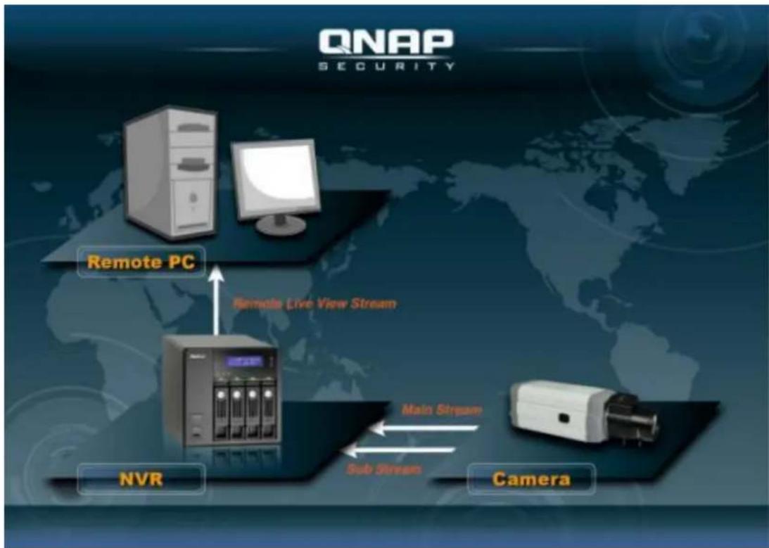
flowchart
graph TD
    A["Remote PC"] --> B["NVR"]
    B --> C["Camera"]
    C --> D["Main Stream"]
    D --> E["Sub Stream"]
    E --> F["Remote Live View Stream"]
    F --> A
The mul-stream technology was already supported by VioStor NVR before rmware
v4.1.0. However, stream properes such as resoluon, frame rate, and compression mechanism could not be changed by users.
![Properties General | Streaming Use custom settings Always stream from the server Always stream from the network camera OSD Settings OSD text color: Display Mode FR image to window Keep aspect ratio Display image in original size. If the image is larger than the window, do the following: Shrink image to fill window, maintaining aspect ratio Shrink image by 1/2, 1/4, 1/8 ... and so on to fill window Video Processing Deinterlace Video Resolution Stream from server Adjust resolution automatically Fixed resolution 4VGA[H264] DCR[MPG] VGA[H264] 4VGA[H264] Let me choose other cameras to apply the same settings OK Cancel](/content/2026/05/1128063/images/eb53d8fef26c33b4eca45a3550ecc146761ddd812b7f88e733bba9168f5b929d.jpg)
The mul-stream feature in rmware v4.1.0 has been enhanced. Users can congregate stream properes aer selecng "User Dened" from the drop-down list on the user interface, and users can choose stream properes based on their needs.
Please note that in the Mul-Stream Prole, the default value is "System-Congured".
Smart Recording
Smart Recording is a powerful feature in the eld of digital surveillance as high quality videos are recorded during an unexpected event, and the low quality camera stream is used for regular recording. This is extremely beneficial as more details about an event can be revealed from the high denion camera stream recorded during that event, and less storage space is consumed comparing to when the high quality camera stream is used for Round-the-clock recording.
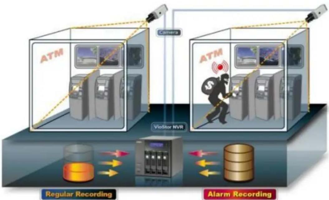
flowchart
graph TD
    subgraph_ATM_1["ATM"]
        A["Camera"] --> B["VG/Storage System"]
        B --> C["VioStor NVR"]
        C --> D["Regular Recording"]
        D --> E["Data Flow"]
        E --> F["Alarm Recording"]
    end
    subgraph_ATM_2["ATM"]
        G["Camera"] --> H["VioStor NVR"]
        H --> I["Regular Recording"]
        I --> J["Data Flow"]
        J --> K["Alarm Recording"]
    end
The VioStor NVR supports two recording modes: Round-the-clock Recording mode and Smart Recording mode, and they are described below:
- Round-the-clock Recording mode: The same stream from the camera is used for both regular recording and alarm recording. To use this funcon, please select one camera stream from the stream list.
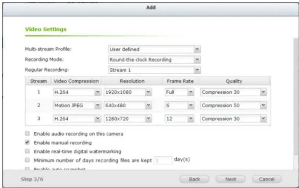
● Smart Recording mode: Dierent camera streams are used for regular recording and alarm recording. To use this funcon, please select one camera stream for regular recording and another for alarm recording.
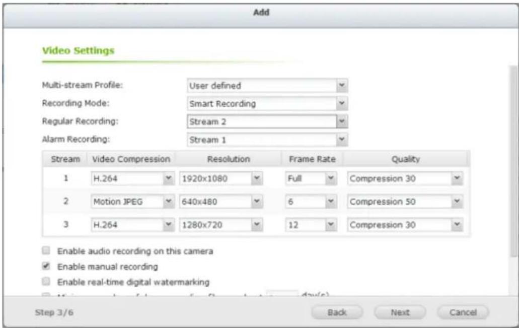
As more cameras will be supported for Smart Recording in the future, please be sure to check out our camera compatibility list from me to me for your camera selecon.
How to Congure Smart Recording?
- Go to the "Camera Congure" to add a camera which supports user dened mul-stream.
- Click 'Next' for recording sengs.
- Select "User denied" from the "Mul-stream Prole" dropdown list.
- Select "Smart Recording" from the "Recording Mode" dropdown list.
- Select camera streams for recording modes.
- Select one camera stream from the "Regular Recording" dropdown list.
- Select a dierent camera stream from the "Alarm Recording" dropdown list.
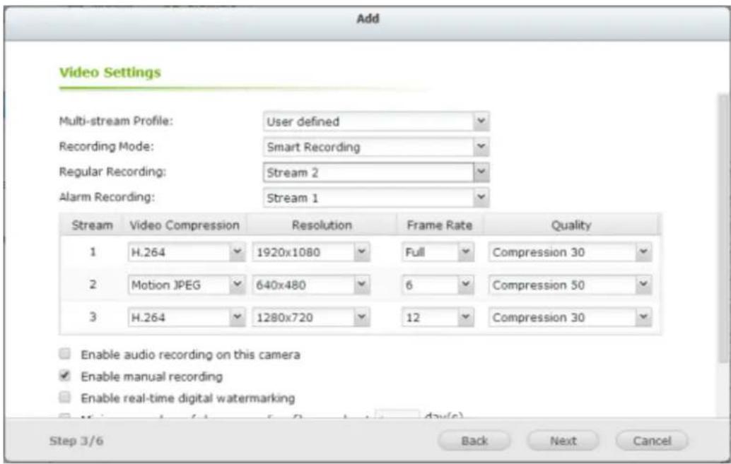
Please note: Scheduled Recording and Alarm Recording must be enabled rst.
Limitaons and Restricons:
- A camera stream can only be selected as for either Regular Recording or Alarm Recording.
- The number of streams supported and stream properes (such as codec, resoluon, frame rate and quality) vary based on camera models, and the same property value may not be available as other properes are changed. For example: if H.264 or Full HD is selected as the video compression seng for stream 1, users may only be le with M-JPEG or VGA for stream 2. This is a camera limitaon.
- Please refer to our camera compatibility list for supported camera models.
- Because more bandwidth is required for Smart Recording, please esmate your bandwidth usage before using this feature. Take Vivotek IP8132 for example, this model oers three streams. Stream 1 uses 663Kbps, Stream 2 uses 1000Kbps and Stream 3 uses 3000Kbps (Please refer to Vivotek Video Transmission Calculator for detail.) The total bandwidth required is 4663Kbps (663K + 1000K + 3000K). If 30 Vivotek IP8132 cameras are connected to a NVR for live view and Smart Recording is used, at least 133930Kbps bandwidth is required.
Edge Recording
How to Congure Edge Recording?
1. Go to the camera sengs page.
Before adding this camera to the NVR, please ensure that the camera me is synchronized with that of the NVR.
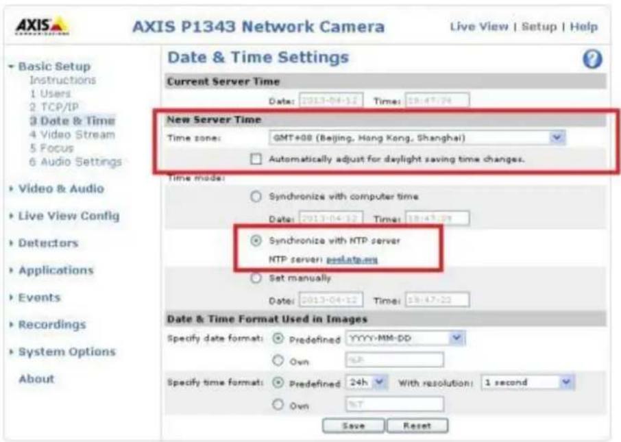
The NVR will apply the sengs in the edge prole to the AXIS camera automacally.
The codec seng of videos recovered from Edge Recording is xed as H.264.
![Stream Profile Settings Stream Profile Profile name: NVRedgeProfile Video encoding: H.264 Description: NVR edge profile Image Audio H.264 MJPEG Image Appearance ✓ Resolution: 640x480 (4:3) ✓ Compression: 50 [0..100] ✓ Mirror image: Off Video Stream ✓ Maximum frame rate: ○ Unlimited ● Limited to 15 [0..30] fps Overlay Settings □ Text and/or image overlay none](/content/2026/05/1128063/images/24703fd0395979002755d8c15719ae4b184cfa59205ddb03c41209e7ff58074b.jpg)
Aer enabling Edge Recording, please check if the camera is recording videos. If not, please enable "Connuous Recording" and make sure that the SD card is not full or damaged.
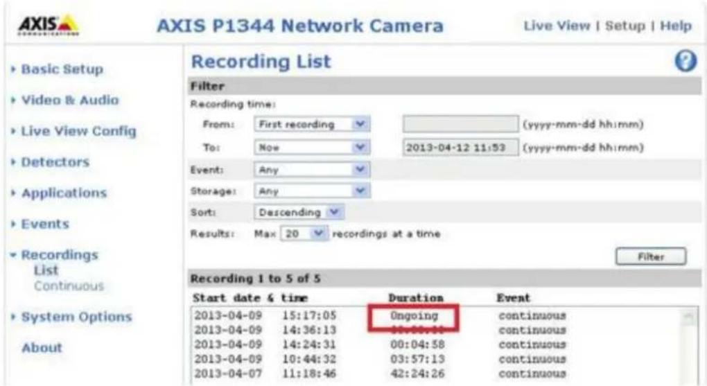
Aer enabling Edge Recording, please make sure that "Recording Sengs" have been enabled on the camera page and select "NVRedgeProle" as the stream prole.
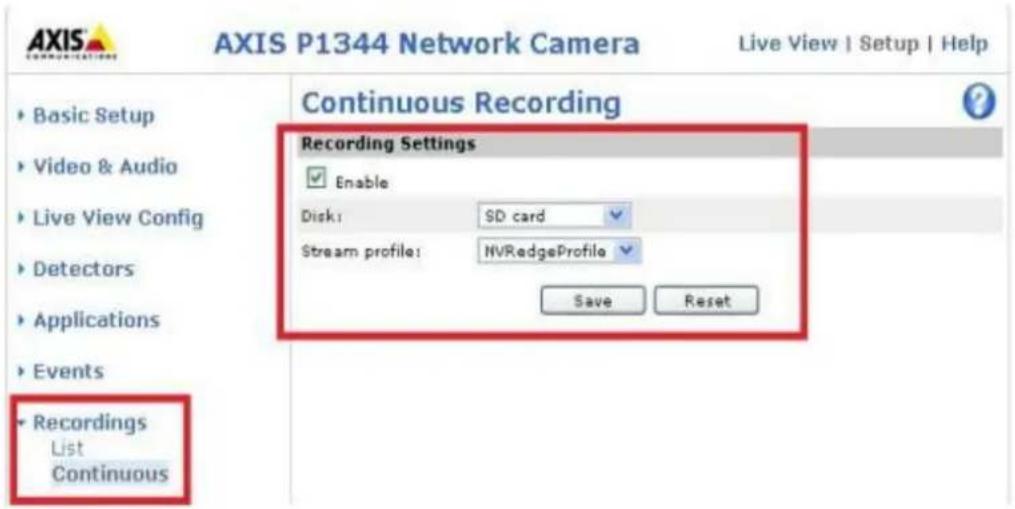
Please conjure the "Remove recordings older than" seng for the SD-card.
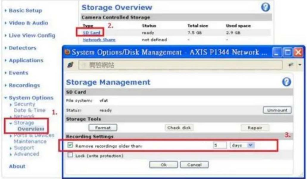
- Go to the Camera Sengs page.
Please enable Edge Recording.
- Go to "Surveillance Setngs" >"Recovery Management" to congregate the recovery schedule, and check the recovery status and the status of Edge Recording aempts.
Applied models: AXIS P1343, P1344, P3343, P5534, M5013, Q1602
Limitaons and Restricons:
- The camera audio funcon is not supported by Edge Recording.
- The camera me must be synchronized with the NVR me for this feature to work.
- Please refer to the camera user manual to nish related sengs on the camera
page.
- Modicaon of Edge Recording related conguraon is not supported on local display
- Please make sure that the SD card can funcon properly and is formatted to VFAT and not EXT4.
- The codec seng of videos recovered from Edge Recording is xed as H.264.
- Edge Recording will only check and recover recording les in the scheduled period.
- Please refer to our camera compatibility list for your camera selecon. hp://www.gnapsecurity.com/pro_compatibility_camera.asp
7.1.2.1 Flexible Channel Mode
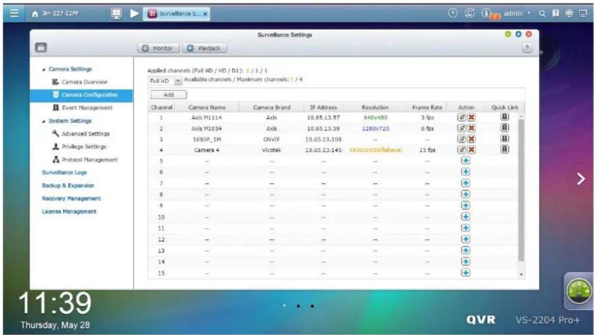
Applicable to the VS-2200 Pro+ series (including VS-2212 Pro+, VS-2208 Pro+, VS-2204 Pro+). Switch to the exible channel mode on QVR desktop -> [Surveillance Sengs] -> System Sengs] -> [Advanced Sengs]
Denions:
D1 here means the number of channels where the recording resolution is lower than D1.
HD here means the number of channels where the recording resolution exceeds D1, but is lower than HD.
Full HD here means the number of channels where the recording resolution exceeds HD.
Applied Channels (Full HD/ HD/ D1) mean the number of channels where the recording resolution exceeds HD, exceeds D1, but is lower than HD and will be lower than D1 respectively
(Full HD/ HD/ D1) Available channels/ Maximum channels mean the number of (Full HD/ HD/ D1) channels you can add and the maximum number of (Full HD/ HD/ D1) channels.
Under the exible channel mode, the number of actual recording channels will vary depending on the recording resolution of added channels. The system will calculate
the number of actual recording channels by using the recording resoluon index automacally. The recording resoluon index of Full HD channel, HD channel, and D1 channel is 4, 2 and 1. The amount of recording resoluon indexes of the device cannot exceed 4 mes the number of camera licenses. Taking VS-2212 Pro+ as an example, aer changing to the exible channel mode, the maximum number of recording channels will be 48. You can add up to 48 channels with (max) D1 resoluon, 24 channels with (max) HD resoluon, or 12 channels with Full HD resoluon. Or you can add 16 channels with (max) D1 resoluon, 8 channels with (max) HD resoluon, and 4 channels with Full HD resoluon.
If you change to the exible channel mode, some advanced features will be disabled, such as user-dened mul-stream, smart recording, dual recording, edge recording, auto snapshot, advanced event management, auto cruising, remote replicaon, storage expansion, and Qstart.
7.1.3 Event Management
The NVR provides ‘Tradional Mode’ and ‘Advanced Mode’ for event management. Select ‘Tradional Mode’ to use the standard alarm sengs in response to the alarm events. To use advanced event management, select ‘Advanced Mode’.
Traditional Mode
1. Alarm Sengs
Select a channel (IP camera/video server) on the list and congregate the alarm sengs. The video recording will be acvated when the alarm input of the selected channel is triggered or a moving object is detected.
When the opon ‘Acvate alarm recording only on selected schedule’ is enabled, the alarm recording will be acvated only when the alarm input is triggered or a moving object is detected within the schedule. To apply the same sengs to all the channels on the list, click ‘Apply to all cameras’.
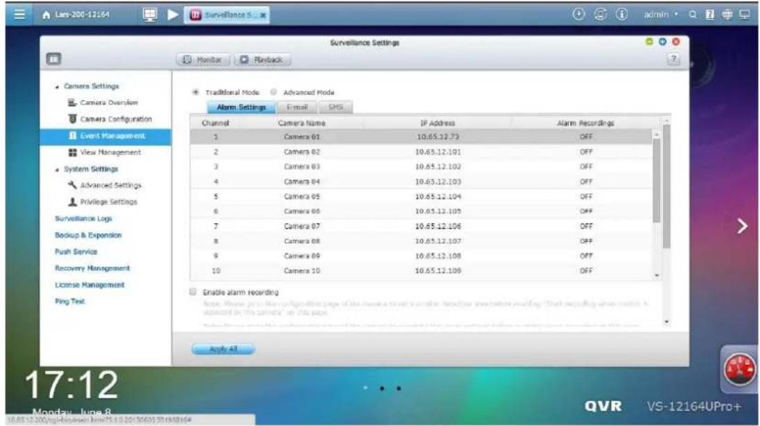
Note:
- All the sengs will be eecve aer clicking 'Apply'. When applying the changes, the current recording process will temporarily pause (maximum 1 minute) and then restart.
- To avoid blocking by the rewall, the IP cameras or the video servers congured for alarm recording must be located on the same subnet as the NVR.
- To switch from traditional mode to advanced mode, select 'Advanced Mode' and click 'Go to the sengs page'.
2. E-mail

SMTP Server
Supports sending email alerts to inform administrators of system errors and warnings. To receive email alerts, congure the SMTP server.
E-mail (SMTP) server address: Enter the SMTP server name, for example, smtp.gmail.com.
Port number: Enter the port number for the SMTP server. The default port number is 25.
Email: Enter the email address of the person to receive the alerts.
User name and Password: Enter the login informaon of the email account.
Secure conncon: Choose SSL or TLS to ensure a secure conncon between the NVR and SMTP server, or None based on your needs. It is recommended to enable this funcon if the SMTP server supports it.
Email Nocaons
If you enable nocaons for all error alerts, you will (by default) receive nocaons when cameras disconnect and recording failure events occur. If you enable nocaons for all warning alerts, you will (by default) receive nocaons when moon detecon and alarm input events occur. You can toggle nocaons for specific surveillance events here.
A maximum of ve email addresses are allowed.
Advanced Sengs
To avoid excessive alert emails due to similar surveillance events, you can set a me period here. Aer conguraon, you will not receive alert emails for similar surveillance events in the dened period of me.
The sengs here, except the nocaons for specific surveillance events and advanced sengs, will be synced with [Control Panel] -> [System Sengs] -> [Nocaon].
3. SMS
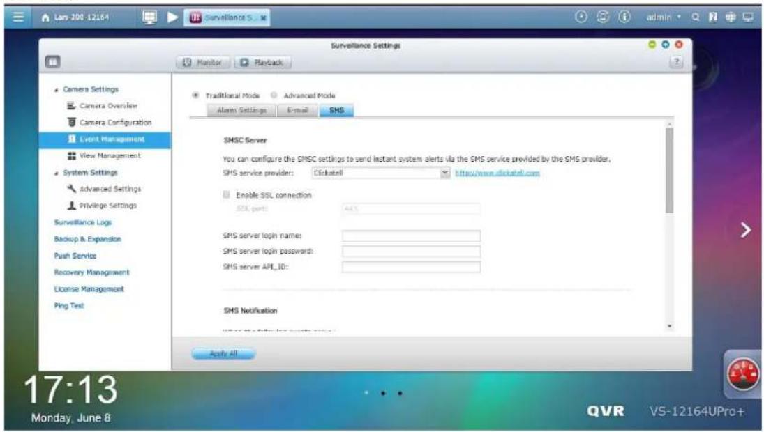
SMSC Sengs
Congure the SMSC server sengs to send SMS messages to the specied phone number(s) from the NVR. The default SMS service provider is Clickatell.
You can add your own SMS service provider by selecng "Add SMS Provider" from the drop-down menu.
When “Add SMS service provider” is selected, enter the name of the SMS provider and the URL template text.
Note: The URL template text must follow the standard of the SMS service provider to receive the SMS alert properly.
SMS Nocaon
If you enable nocaons for every error alert, you will decide whether you receive an SMS message when cameras disconnect and recording failure events
occur. You can also decide whether you want to receive SMS message when moon detecon and alarm input events occur. You can toggle SMS messages for specific surveillance events here.
A maximum of two phone numbers are allowed.
Advanced Sengs
To avoid excessive SMS messages due to similar surveillance events, you can set a me period here. Aer conguraon, you will not receive SMS messages for similar surveillance events in the dened period of me.
The sengs here, except the nocaons for specific surveillance events and advanced sengs, will be synced with [Control Panel] -> [System Sengs] -> [Nocaon].
Advanced Mode
The advanced mode consists of the event and acon seconds. Dene the acon to take for each event triggered on the IP cameras or the video servers connected to the NVR.
To conjure the advanced event management by the ‘Advanced Mode’, select an event type on the le event list and conjure the acons to take on the right.
Note:
- Click 'Apply' to apply the sengs or 'Exit' to exit the sengs page. If the 'Advanced Mode' is selected on the 'Alarm Sengs' page, the advanced sengs will be applied aer the NVR restarts even if you have selected to exit the sengs page. The sengs will be cancelled if 'Tradional Mode' is selected aer exing the 'Advanced Mode'.
- To avoid blocking by the rewall, the IP cameras or the video servers congured for the alarm recording must be located on the same subnet as the NVR.
- To switch from the advanced mode to the tradional mode, select 'Tradional Mode' and click 'Apply'.
Events:
The events supported by the NVR are classified as camera events (moon detecon, alarm input, camera disconnexcon), NVR events (recording failure), and external events (user-dened events).
Note: The camera events available depend on the features supported by the IP cameras or video servers.
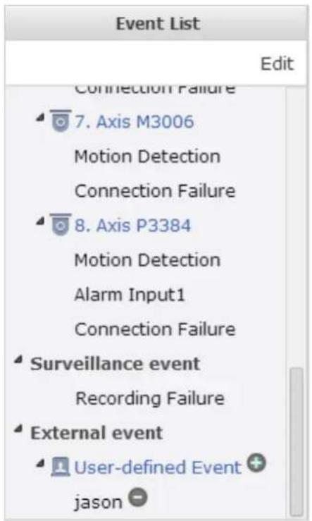
| Buon | Descripon |
| Edit | Edit an event. This buon cannot be used to edit camera disconncon. |
 | Add an external event. This buon is not applicable to the camera events and the NVR events. |
 | Delete an external event. This buon is not applicable to the camera events and the NVR events. |
The NVR supports the following event types. Before specifying the acon sengs, select the events to manage and congure the sengs.
1. Moon detecon
This opon allows the NVR to trigger an acon when a moving object is detected by the IP camera or the video server. Select 'Camera event' from the 'Event List'. Locate the channel and click 'Moon Detecon'. Next, click the edit buon, enable this opon, conjure the sengs, and click 'Apply'. Set the schedule to dene the acve period of the alarm sengs and dene the acon on the right (discussed in the later seconds).
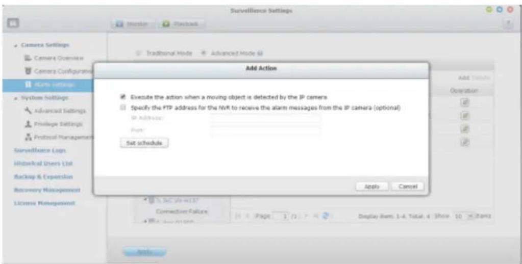
2. Alarm input
This opon allows the NVR to trigger an acon when the alarm input of the IP camera or the video server is triggered. Select 'Camera event' from the 'Event List'. Locate the channel which supports alarm input and click 'Alarm Input'. Next, click the edit buon, enable this opon, conjure the sengs, and click 'Apply'. Set the schedule to dene the acve period of the alarm sengs. Aer that, dene the acon on the right (discussed in the later seconds).
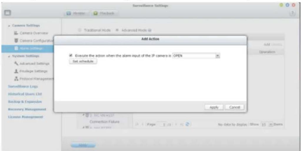
3. Alarm event
The alarm input and the moon detecon sengs of some IP cameras or video servers may be combined together and called ‘Alarm Event’ on the Event List. Edit the event sengs and dene the acon on the right (discussed in the later seconds).
4. Connecon failure
This opon allows the NVR to trigger an acon when the IP camera or the video server is disconnected. Select 'Camera Event' from the 'Event List'. Locate the channel and click 'Connecon Failure'. Aer that, dene the acon on the
right (discussed in the later seconds).
5. Recording failure (NVR event)
This opon allows the NVR to trigger an acon when the video recording of the IP camera or the video server fails due to the hard disk bad blocks, le system crash, or other reasons. Select 'NVR event' from the 'Event List'. Click 'Recording failure'. Then dene the acon sengs on the right (discussed in the later seconds).
6. External event (user-dened events)
To create a self-dened event on the NVR, select 'User-dened Event' under 'External event' on the 'Event List'. Then click the + buon. Enter the event name, for example, 'door'.
Aer creang an event, click the event name and dene the acon on the right (discussed in the later seconds). Aer conguring the acon sengs, enter the CGI command (including the self-dened event name) in the web browser to trigger the acon anymore. The format of the CGI command is:
hp://NVRIP/cgi-bin/logical_input.cgi?name=event-name. For example, hp://10.8.12.12:80/cgi-bin/logical_input.cgi?name=door
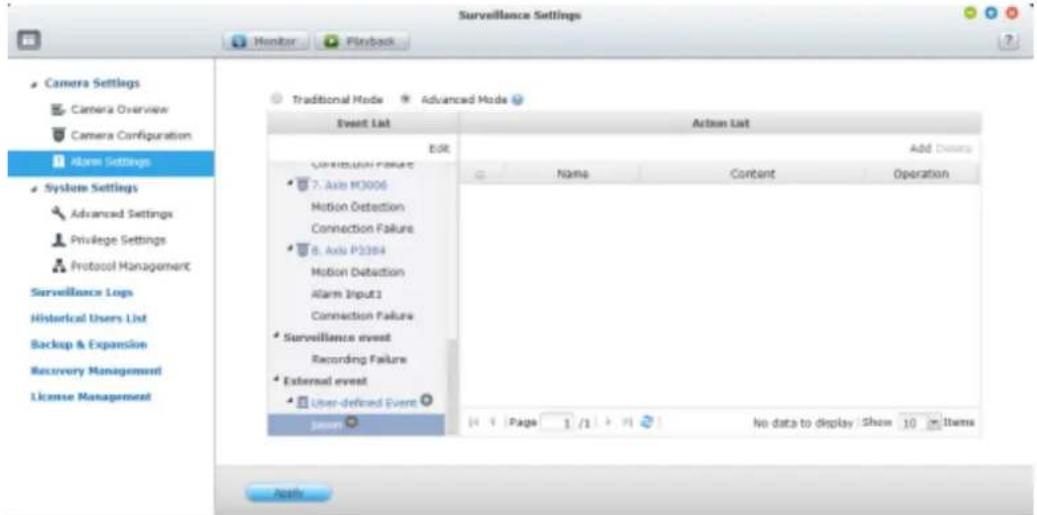
Event schedule sengs:
When eding an event (not including camera disconncon, NVR events, and external events), click 'Set Schedule' to dene when the alarm sengs will be acve.
To create a new schedule, select 'New' and enter a schedule name. The schedule supports a maximum of 25 characters (double-byte characters, spaces, and symbols are allowed). Select the day and me when the alarm sengs should be acve.
Click + to add a schedule; or – to delete a schedule. Up to 6 sengs can be dened for each schedule.
The sengs will be shown on the graphical table. Click 'Apply' to save the sengs.
To use the same schedule for all the events, click 'Apply to All Events'. Select to use the default schedule or a formerly created schedule from the list. The default alarm sengs are acve all day, every day.
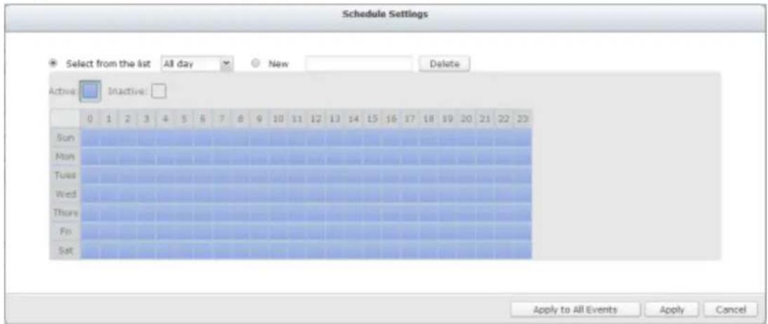
Acons:
The NVR supports dierent acons which can be acvated when the selected events are triggered on the IP cameras or the video servers. The acons include video recording, email alert, SMS alert, buzzer, PTZ camera control, alarm output, and logic output.
| Buon | Descripon |
| Edit an acon:Select an event on the le. All the acons denied for this event will be shown. Select the box in front of the acon name to edit. Then click this buon on the ‘Acon’ column to edit the acon sengs. | |
| Add | Add an acon:Aer conging an event on the le, click ‘Add’ to create an acon in response to the event. Click ‘Apply’ to save the sengs. |
| Delete | Delete an acon:Select an event on the le. All the acons denied for this event will be shown. Select the box in front of the acon name to delete and click ‘Delete’. Mulple acons can be deleted. |
Note: Please ensure the acon in the event sengs has been enabled; otherwise the acon will not be executed.
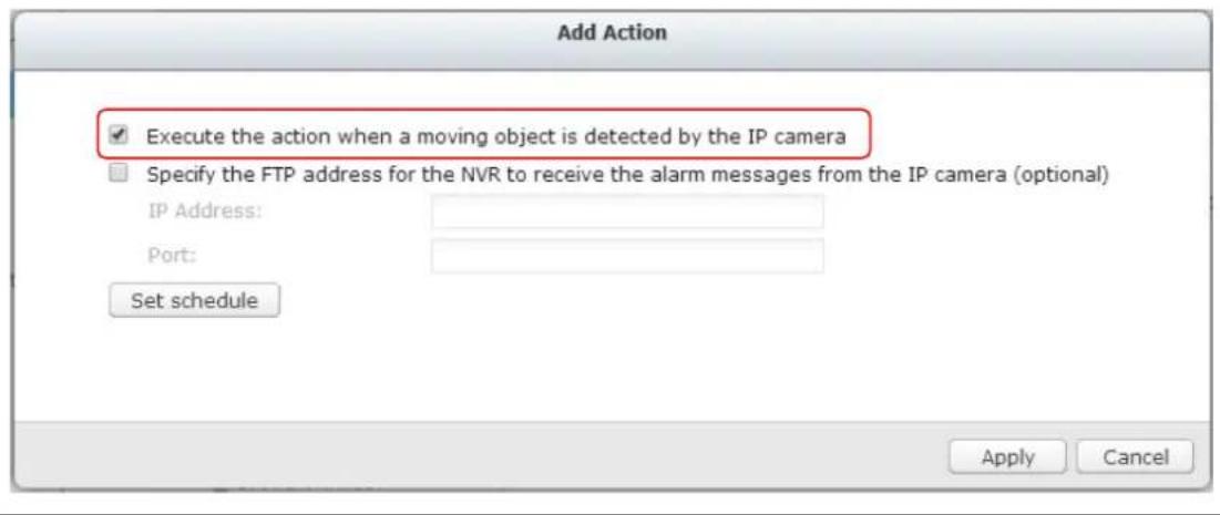
1. Recording
Select the channels (IP cameras or video servers) which will start recording when an event occurs. The following opons are also available:
A. Enter the me (in seconds) the recording should be executed aer the event has been triggered.
B. Start recording when the event starts and stop recording when the event ends.
Opon (ii) is applicable to duraon events only. A duraon event is an event with a start and end me and lasts for a set period of me. It does not include the events related to status changes, such as a camera disconncon or NVR recording failure.
If the acon is triggered by a duraon event and both sengs (i, ii) are enabled, the NVR will execute the second seng (ii) only.
Click 'Select from the list' to select an acon seng which has been congured before.
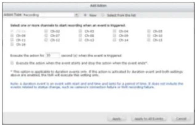
2. Camera control
Congure the PTZ camera to adjust to the preset posion for monitoring or act according to the HTTP URL entered when an event is triggered. Select a preset posion from the drop-down menu or enter the HTTP URL.
Click 'Select from the list' to select an acon seng which has been congured before.
Note: The preset names will appear only aer the preset sengs of the PTZ cameras have been congured.
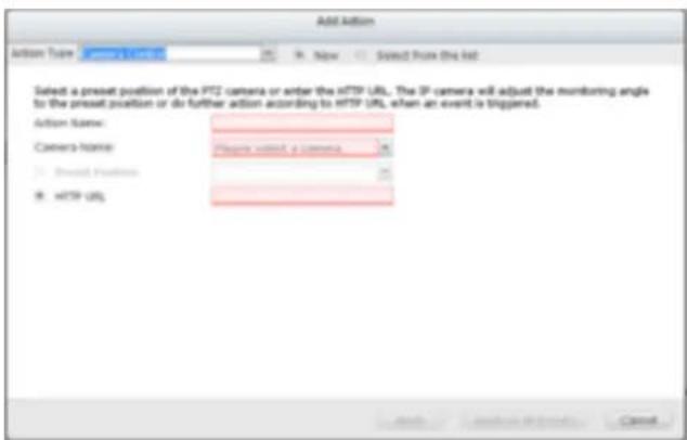
3. Alarm output
Select to acvate the alarm device connected to the IP camera when an event is triggered. The following opons are available:
A. Enter the number of second(s) the alarm device will be acve for when the event is triggered.
B. Acvate the alarm device when the event starts and stop the alarm device when the event ends.
The opon (ii) is applicable for duraon events only. A duraon event is an event with a start and end me and lasts for a set period of me. It does not include the events related to status change, such as a camera disconncon or NVR recording failure.
Click 'Select from the list' to select an acon seng which has been congured before.
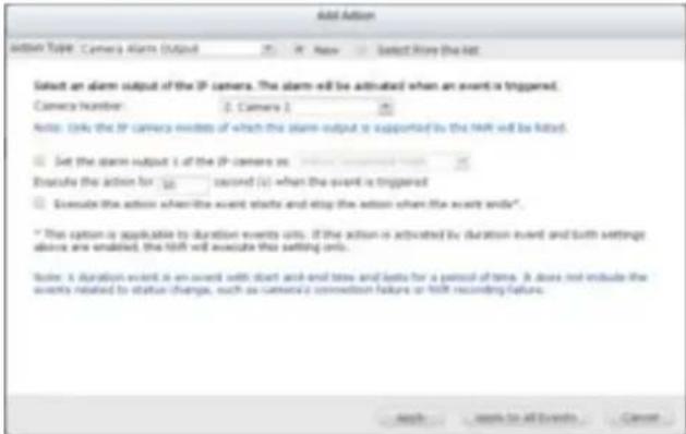
4. Email
To receive an instant email alert when an event is triggered, enter the SMTP sengs. Mulple email addresses can be entered as the recipients.
Snapshots of mulple channels (IP cameras/video servers) can be aached to the alert emails.
Click 'Select from the list' to select an acon seng which has been congured before.
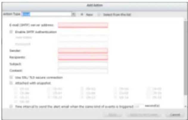
5. SMS
To allow the system administrator to receive an instant SMS alert when an event is triggered, enter the SMS server sengs. The default SMS service provider is Clickatell. To add other SMS service providers, click 'Add' and enter the provider's name and the URL template text.
Click 'Select from the list' to select an acon seng which has been congured before.
Note: Always follow the standard of the SMS service provider to receive the SMS properly.
![Add Caption Button Type: New Select from the list [SMS Server Settings] Checkbox Enable SSL Connection SMS Server Login Name: sidesn SMS Server Login Password: ****** SMS Server APL_ID: [SMS Modification Settings] Country Code: Afghanistan (v10) Call Phone No. 1: Call Phone No. 2: Message : Text Interval of sending SMS text messages of the same events: 30 Minutes(x) Cancel](/content/2026/05/1128063/images/2b74071df748d0ad384c8a8af4d5e8761f2f8ee8fecc060aab76ae4270295020.jpg)
6. Buzzer
Enable the buzzer when an event is triggered. The following opons are also available:
A. Enter the me (in seconds) the buzzer will sound when the event is triggered.
B. Execute the buzzer when the event starts and stop the buzzer when the event ends.
The opon (ii) is applicable to duraon events only. A duraon event is an event with a start and end me and lasts for a set period of me. It does not include the events related to status change, such as a camera
disconnecon or NVR recording failure.
If the acon is triggered by a duraon event and both sengs (i, ii) are enabled, the NVR will execute the second seng (ii) only.
Click 'Select from the list' to select an acon seng which has been congured before.
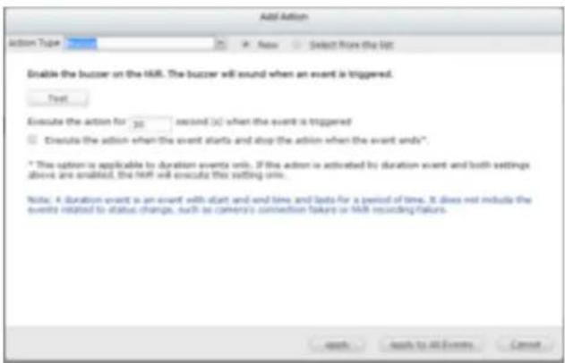
7. User-dened Acon
Add a self-dened acon when an event is triggered. Enter the login account and password, IP address, port, and the HTTP URL of other surveillance devices to manage the devices such as re protecon devices, power controller, and air condioning control.
Click 'Select from the list' to select an acon seng which has been congured before.
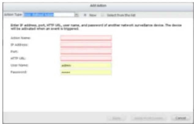
7.1.4 View Management
View Management allows users to customize view layouts, and to assign cameras to specific windows. Users can define view layouts to suit their needs. For example, when the camera provides a corridor view, users can create a rectangle to fit the corridor view.
View Management provides two modes, normal mode is designed for non-fisheye cameras
and fisheye mode is designed for fisheye cameras.
| Icon | Descripon |
 | Edit: Edit view |
 | Remove: Remove view. |
 | View thumbnail : When you hover over, it will show thumbnails to show your customized view. |
Normal Mode
You can choose a customized view in the le view tree list in monitor mode.
Edit View :
-
To add a camera to a view, you can choose a view you want, then drag a camera from the le list to the right channel screen.
-
To remove a camera from a view, you can double click on a camera snapshot or drag it to the le camera tree list. You can also click 'Restore' to remove all of the camera.
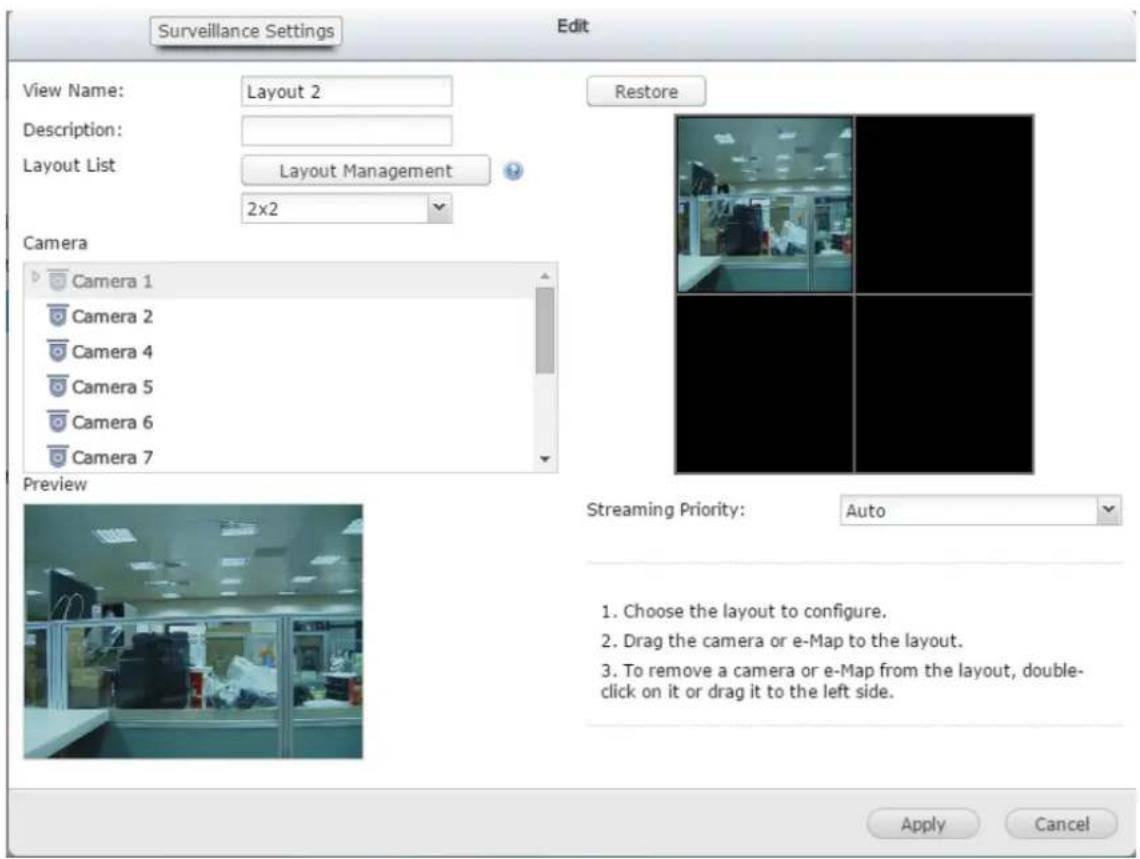
Add customize layout :
You can add a customized layout as a new layout
- To choose a type of layout, for example you can choose 6x6.

- To edit the Layout, you can click a square and draw a larger square. And you can double click the combined region to restore it. Or you can click 'Restore' to restore the original layout.
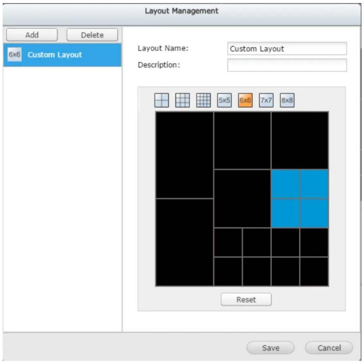
- To nish, click 'Save' and it will show on le tree list.
- To edit the layout, choose the layout, edit it in the right zone, then click 'Save'.
- To delete a layout, choose the layout then click 'Delete'.
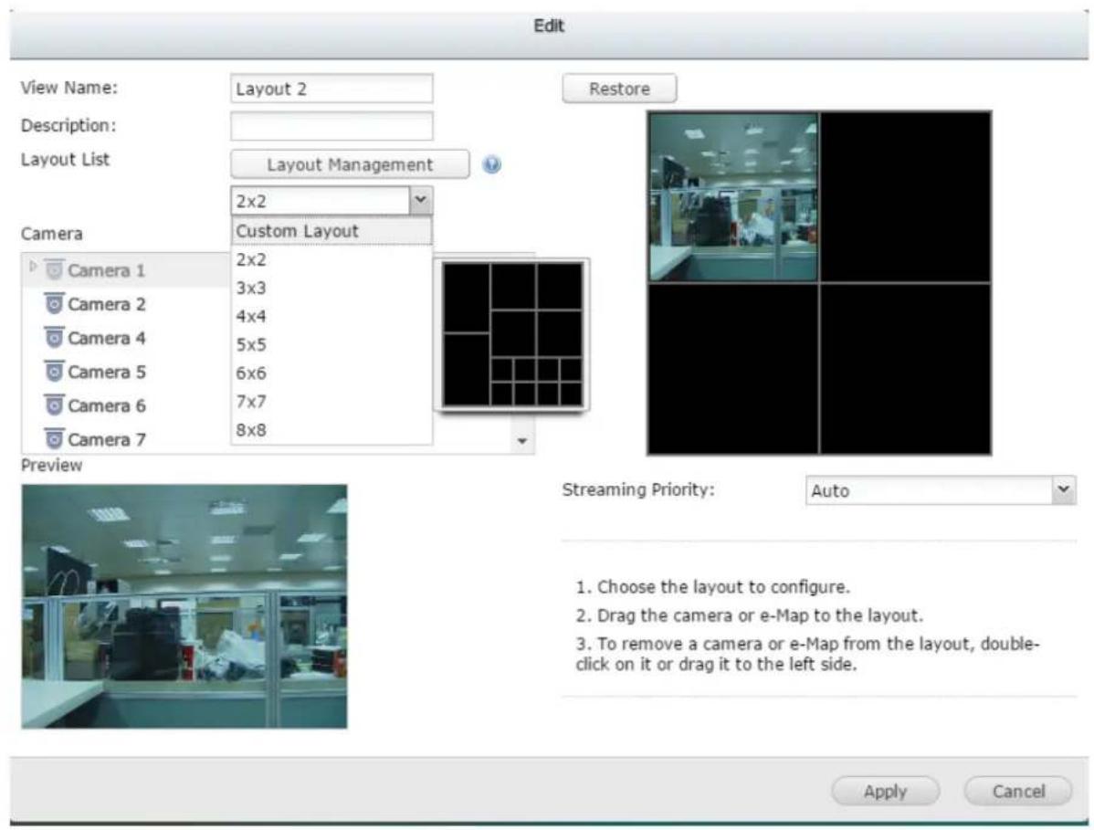
Fisheye Mode
Fisheye mode provides the below view modes:
| View Mode | Descripon |
| 9R Mode | Provides 9 regional screens |
| 4R Mode | Provides 4 regional screens |
| 1O8R Mode | Provides an original screen in the center, and 8 regional screens around it |
| 1P6R Mode | Provides an original screen in the center, and 6 regional screens around it |
| Dual Panorama | Provides 2 panorama screens |
| 1P3R Mode | Provides 3 regional screens in the upper side, and one panorama screen below |
| 1P2R Mode | Provides 2 regional screens in the upper side, and one panorama screen below |
| OPR Mode | Provides one original screen one regional screen, and onepanorama screen |
| 103R Mode | Provides an original screen, and 3 regional screens |
| R Mode | Provides one regional screen |
| Full Panorama | Provides one panorama screen |
View Name: The view name cannot be duplicated. You can nd your customized view mode.
How to edit view mode :
- Choose display mode
- Drag a camera from le camera tree to the right preview.
- To alter the size/drag posion in preview, use the mouse wheel to zoom in/out.
Then you can see the view.
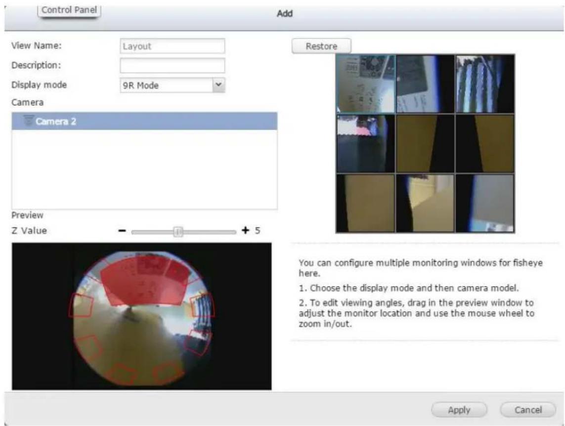
Choose View Mode to monitor
You can also choose the view mode in the le tree's view tab on the monitor.
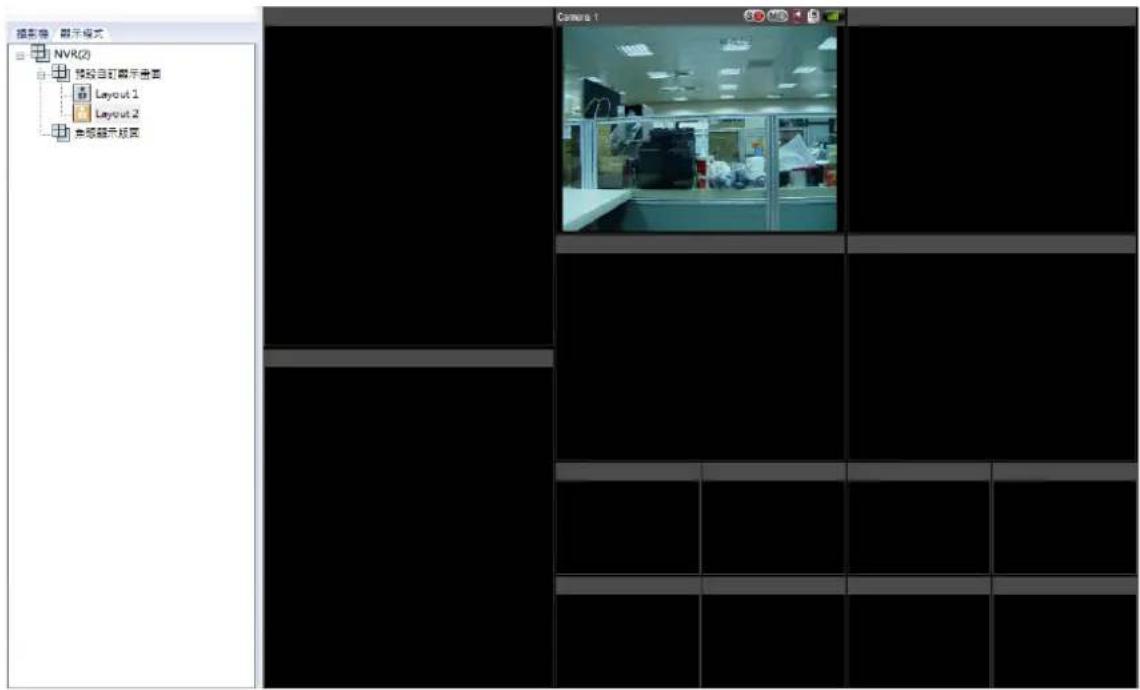
You can congregate the advanced recording sengs in this secon.
● Maximum period for each recording le
Specify the maximum length of each recording le (maximum 15 minutes).
- When the available storage is less than...%
Specify if the NVR should overwrite the oldest recordings or stop recording when the available storage capacity is less than the specified percentage of the total storage capacity.
● Maximum number of days all recording les are kept ... day(s)
Enter the number of calendar days that the NVR should keep the recording les. Please make sure the storage capacity is enough to save the data for the number of calendar days specified. When the recording data has reached the expiry date, all of the expired video les will be deleted. For example, if the NVR is congured to delete the recording data aer 7 calendar days, on the 8th day, the les recorded on the rst day of each camera will be deleted so that the NVR can start to save the data on the 8th day.
● Number of days alarm recording les are kept ... day(s)
Specify the number of days that alarm recordings will be retained.
● Pre-/Post-alarm recordings
■ Start recording video...second(s) before the event occurs: Enter the number of seconds to start the recording before an event occurs.
■ Stop video recording...second(s) aer the event ends: Enter the number of seconds to stop the recording aer an event ends.
The maximum number of seconds for the above sengs is 300 (5 minutes.)
- Local display
To allow guest access to the monitoring screen of the NVR by local display, select 'Enable anonymous access'.
- Auto logo
Set the meout period to log o the users from the conguraon page of the NVR when the idling me has reached.
Note: The meout logo does not apply to the monitoring, playback, advanced mode, device conguraon, system update, remote replicaon, and logs & stascs pages.
● Network intrusion detecon
The system will alert users when possible aacks on the network are detected and give recommendations for acons to take.
● Maximum number of concurrent logins (hp)
You can denote the maximum number of hp user sessions at the same me (maximum: 32.)
Note: All of the sengs will be eecve only aer clicking 'Apply'. When applying the changes, the recording will temporarily pause (for up to 1 minute) and then restart.
7.2.1.1 Flexible Channel Mode Settings
Applicable to the VS-2200 Pro+ series (including the VS-2212 Pro+, VS-2208 Pro+, VS-2204 Pro+)
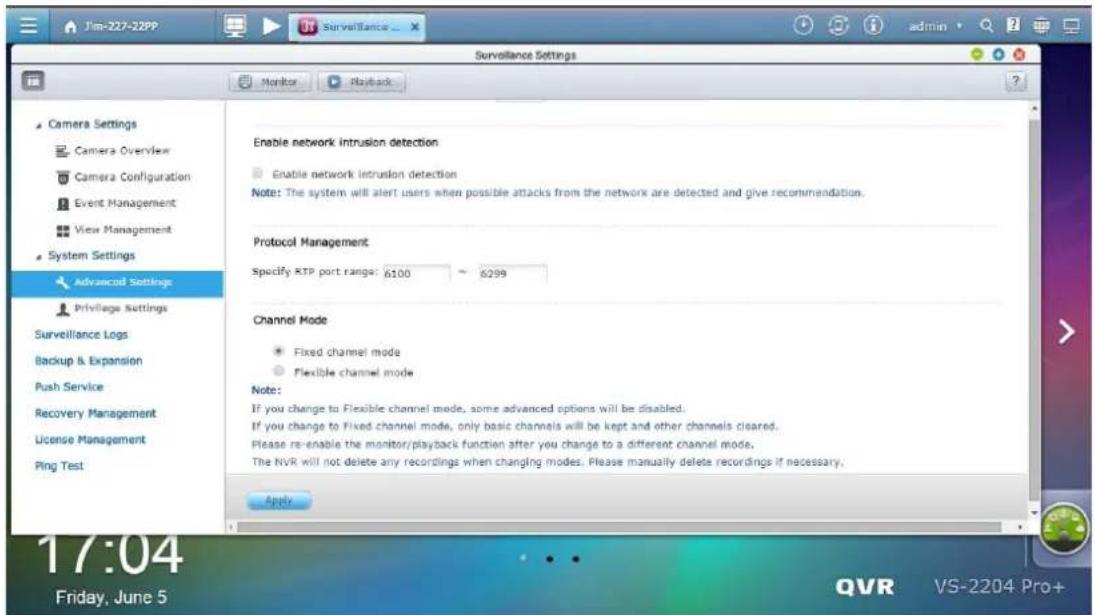
To change the channel mode, go to QVR desktop -> [Surveillance Sengs] -> [System Sengs] -> [Advanced Sengs]. There is the xed channel mode (default) and the exible channel mode.
Aer changing to the exible channel mode, compared with the xed channel mode, the maximum recording channels will become 4. Under the exible channel mode, the number of actual recording channels will vary depending on the recording resoluons of added channels. The system will automacally calculate the number of actual recording channels by the recording resoluon index. The recording resoluon index of Full HD channel, HD channel, and D1 channel is 4, 2 and 1. Using the VS-2212 Pro+ as an example, as long as the amount of recording resoluon indexes does not exceed 48 (=12 * 4), you can add more than 12 cameras.
Note:
- If you change to the exible channel mode, some advanced features will be disabled, such as user-dened mul-stream, smart recording, dual recording, edge recording, auto snapshot, advanced event management, auto cruising, remote replicaon, storage expansion, and Qstart.
- If you change to the xed channel mode, only basic channels will be retained, but not other channels.
The recordings of other channels will not be removed, and if necessary can be manually deleted.
- If you are using the QVR client to see the live view and playback recordings, please re-enable the monitor/playback funcon aer you change to a dierent channel mode.
7.2.2 Privilege Settings
You can check the rights of camera management for all users. You can also modify access right of monitoring, playback, PTZ control, and audio for a general user. If you want to add a user, please go to [Control Panel] -> [Privilege Sengs] -> [Users].
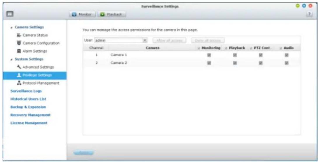
7.2.3 Protocol Management
RTP (Real-me Transfer Protocol) is a standardized packet format for delivering real-me audio and video data of the IP cameras on the Internet. The real-me data transfer is monitored and controlled by RTP (also RTCP). The default seng is 6100–6299. If the IP cameras use dierent RTP ports, enable 'Specify RTP port range' and specify the port numbers.
Note: Make sure the ports have been opened on the router or rewall to ensure normal monitoring and recording.
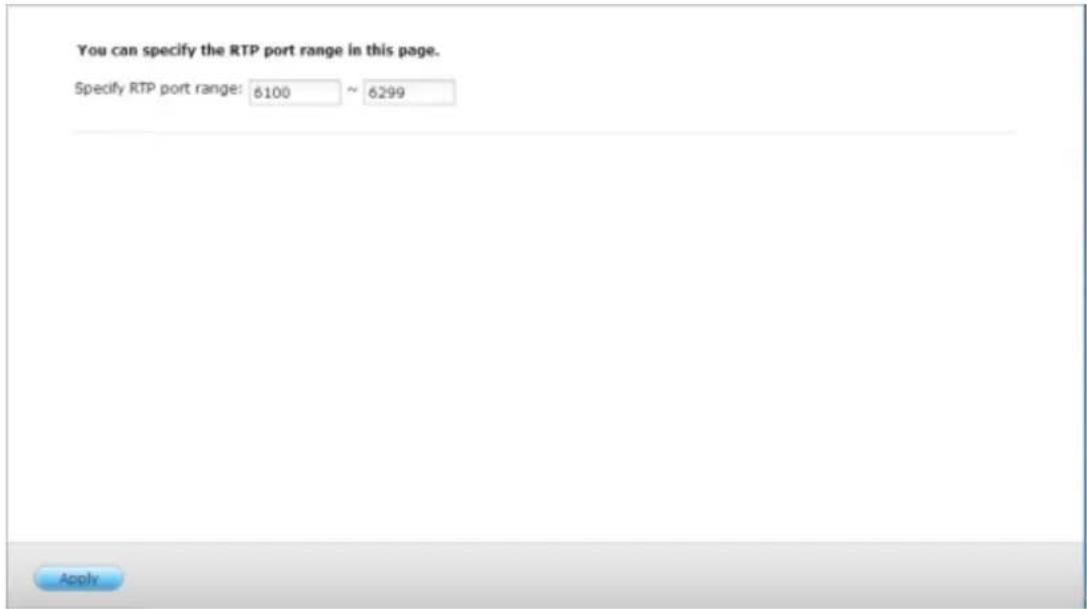
7.3 Surveillance Logs
This page shows the surveillance logs such as camera conneccon, moon detecon, and camera authencaon failure.
This page shows the surveillance logs such as camera connection, motion detection and camera authentication failure.
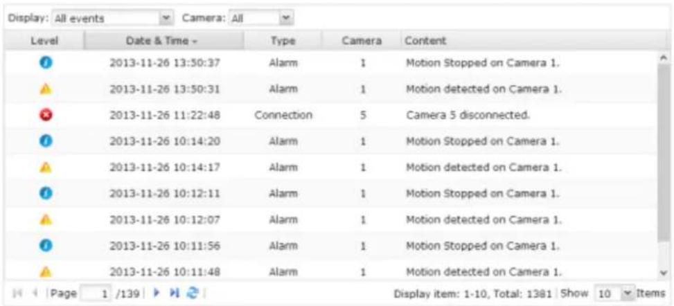

Please Note: The logs are currently only available in English.
7.3.1 Surveillance Logs
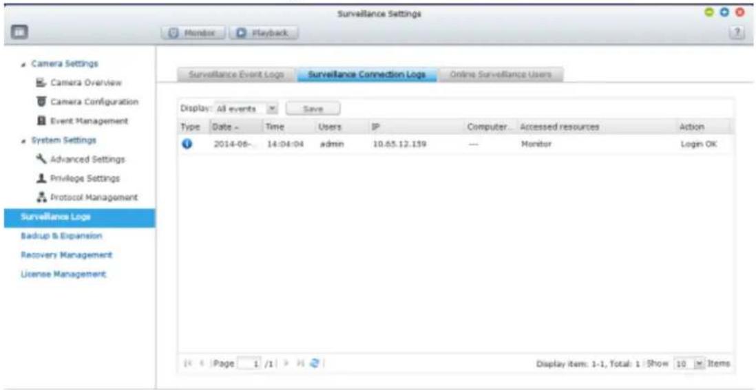
7.4 Push Service
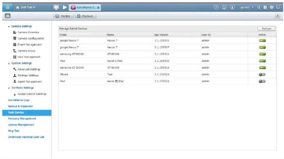
The push service allows you to receive nocaons on mobile devices when moon detecon or alarm events occur. To use the push service, please ensure you have the right to receive push nocaons and enable the myQNAPcloud remote access services on the server. Use the Vmobile App on your mobile devices to add a server for seeing the live view, playback recordings and to receive push nocaons. Aer being added, the informaon of the mobile device will be listed on the page, including the model name, device name, version of Vmobile, and user details on the NVR. You can also disable the push service to specic mobile devices.
7.5 Recovery Management
This page is related to the edge recording feature. You can edit the recovery schedule, monitor the recovery status, and the edge recording status here.
- Recovery Schedule: Schedule for recovery of recorded data. Available when edge recording is in use.
You can edit the recovery schedule in this tab.
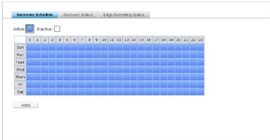
- Recovery Status: Status for the recovery of recorded data. Available when edge recording is in use.
You can monitor the recovery status in this tab.
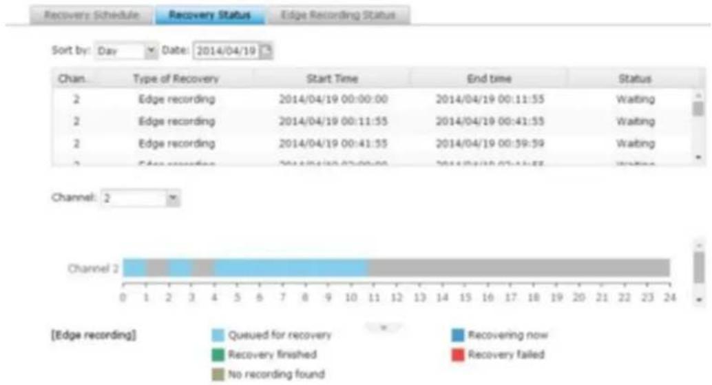
bar
| Channel | Type of Recovery | Start Time | End time | Status | | :--- | :--- | :--- | :--- | :--- | | 2 | Edge recording | 2014/04/19 00:00:00 | 2014/04/19 00:11:55 | Waiting | | 2 | Edge recording | 2014/04/19 00:11:55 | 2014/04/19 00:41:55 | Waiting | | 2 | Edge recording | 2014/04/19 00:41:55 | 2014/04/19 00:59:59 | Waiting | | 2 | Edge recording | 2014/04/19 00:00:00 | 2014/04/19 00:11:55 | Waiting | Channel: 2 Channel 2 [Edge recording] Queued for recovery Recovery finished No recording found Recovering now Recovery failed- Edge Recording Status: Status of edge recording
You can check me synchronizaon between the NVR and cameras, the status of cameras set up for edge recording, and the details of recording les stored on camera's SD card.
Recovery Schedule Recovery Status Edge Recording Status
Server Time: 2013/12/19 10:16:42
| Channel | Brand | Model | Camera Name | Time | Status |
| 1 | Axis | Axis M5013 | 1 M5013 | N/A | Disconnected |
| 2 | Axis | Axis M5013 | 2 M5013 | 2013/12/19 10:16:42 | Ready |
7.6 License Management
The VioStor NVR oers various channel base license depending on dierent models. Aer purchasing a license, you can add extra recording channels.
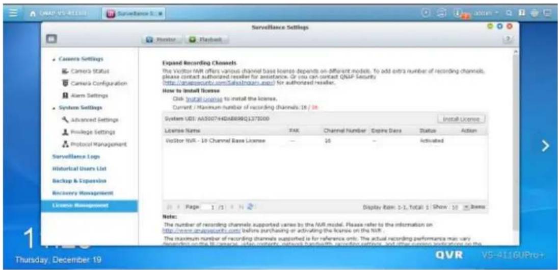
You can click "Install License" to begin installing the license to the NVR.
7.6.1 License Activation
Online Activation
Step1. If your VioStor NVR is connected to the Internet, please select "Online Acvaon".
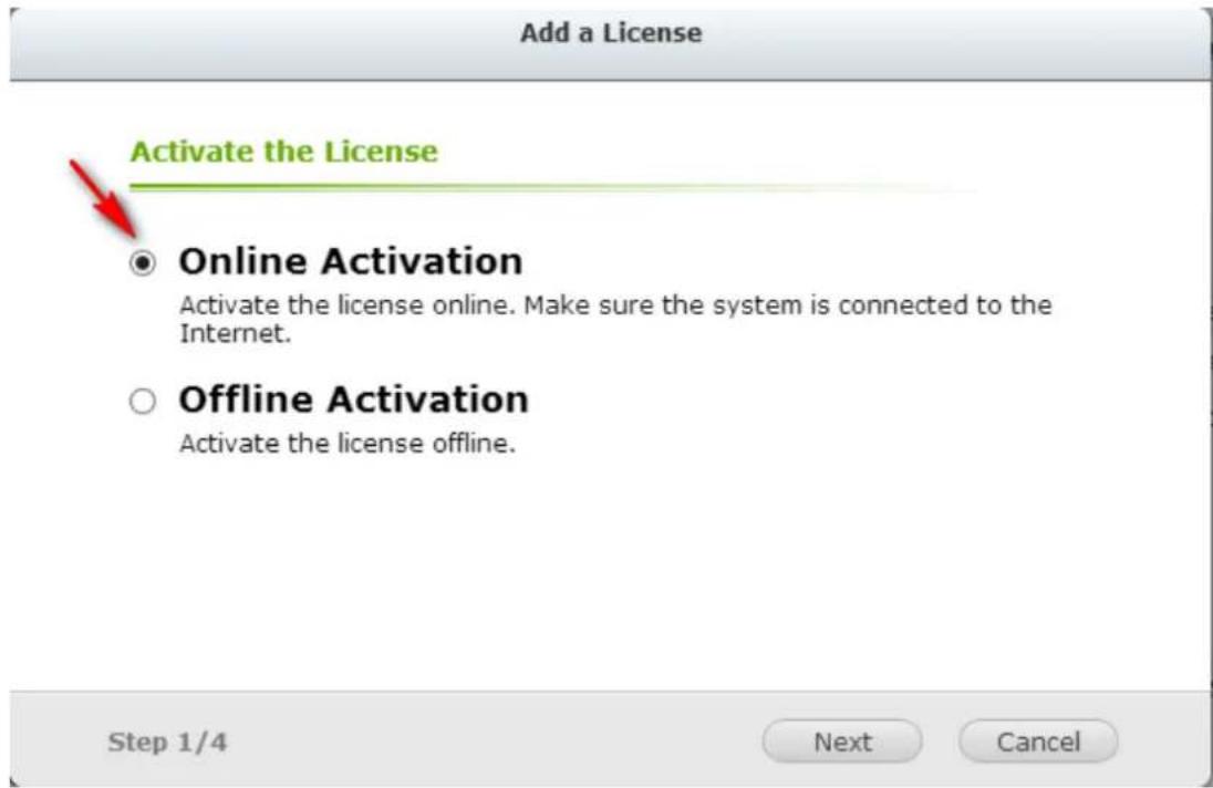
Step2. Enter the Product Authorizaon Key (PAK) code to acvate the license.
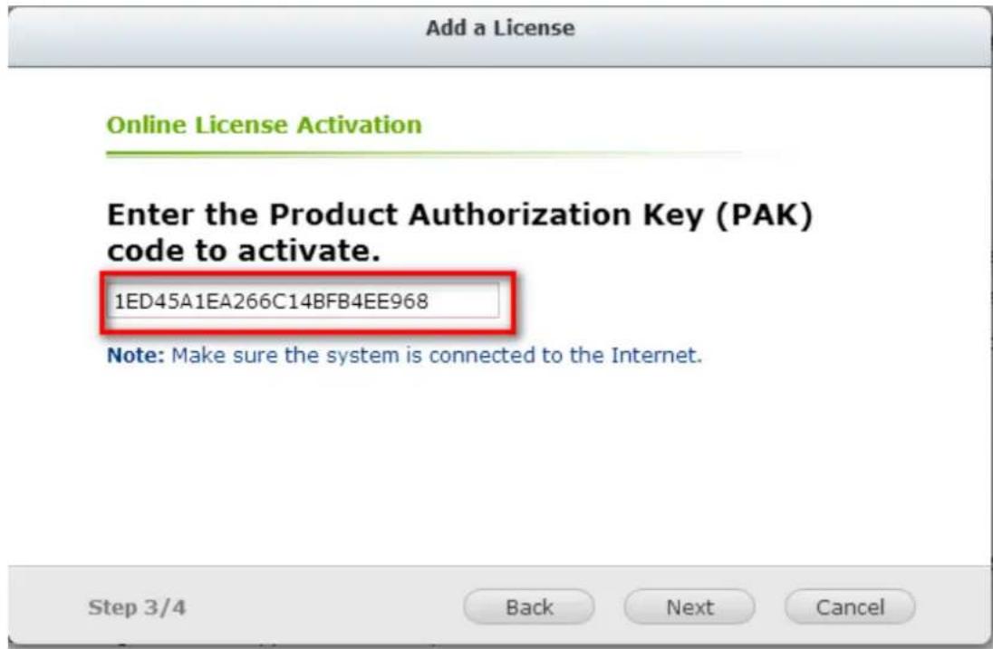
Step3. The License has been acvated. Please click [FINISH] buon to close the window.
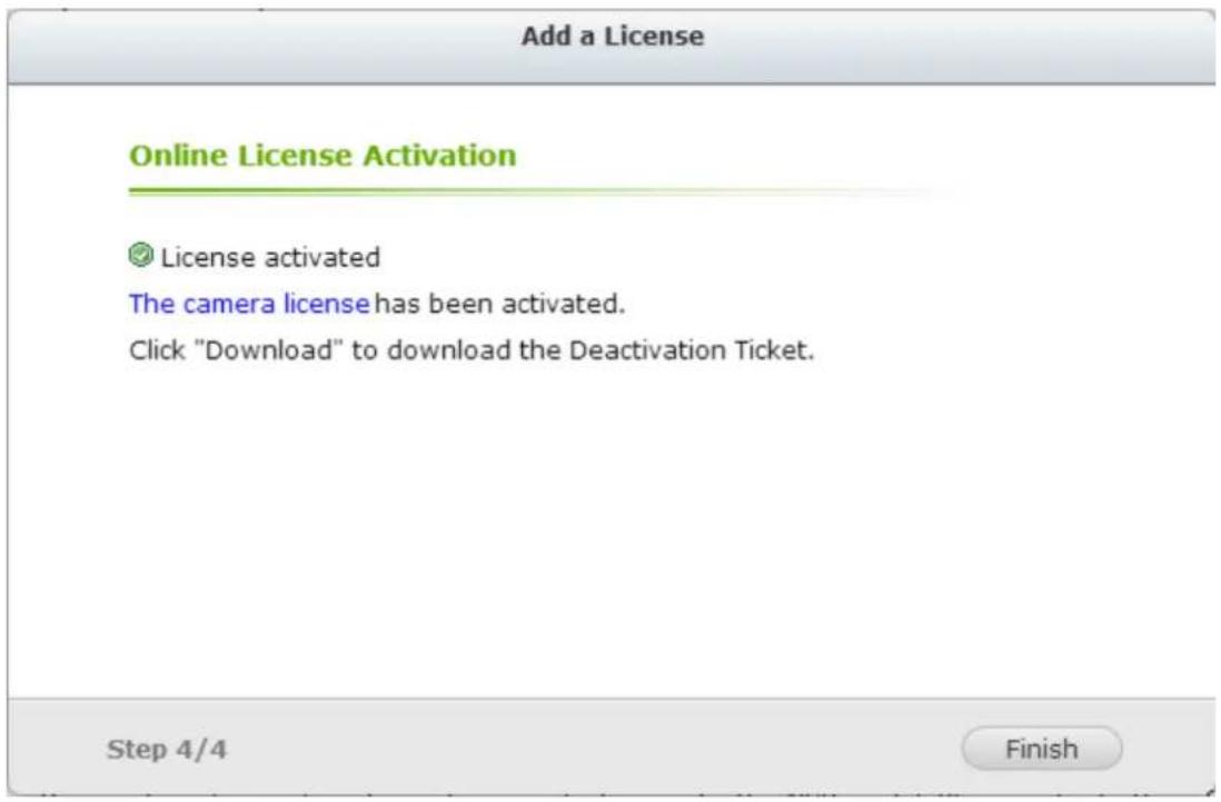
Step4. The additional camera license will be displayed in the license management list aer the license acvaon.
Offline Activation
Step1. If the VioStor NVR is behind a rewall or doesn't have an Internet conncon, please select "Oine Acvaon".
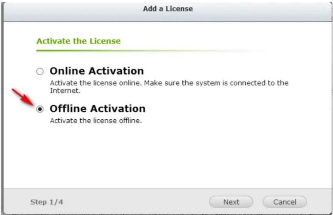
Step2. Please copy the system UDI and go to the License Store for oine license acvaon.
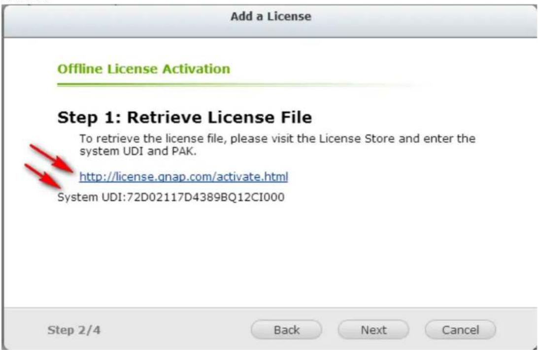
Step3. Please login to the License Store with your registered account.
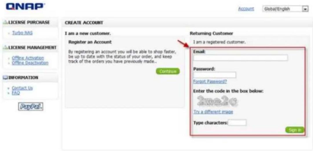
Step4. At Oine Acvaon page, please ll out the UDI and PAK elds and then click the [Acvate] buon.
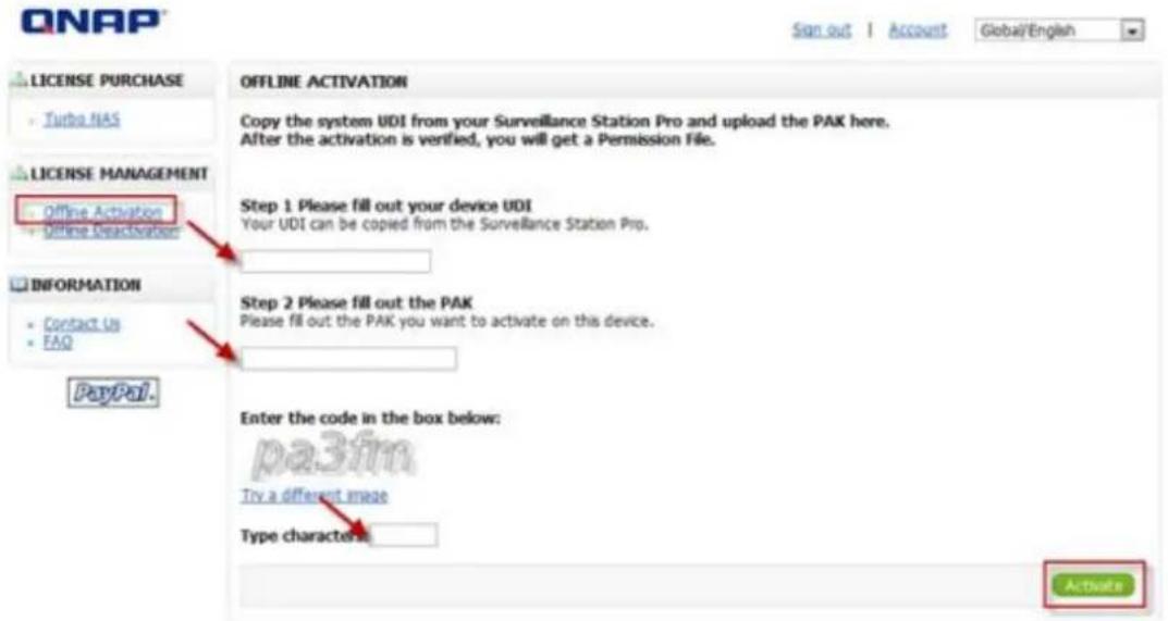
Step5. You will receive an email with an aached permission le aer the oine acvaon is veried.
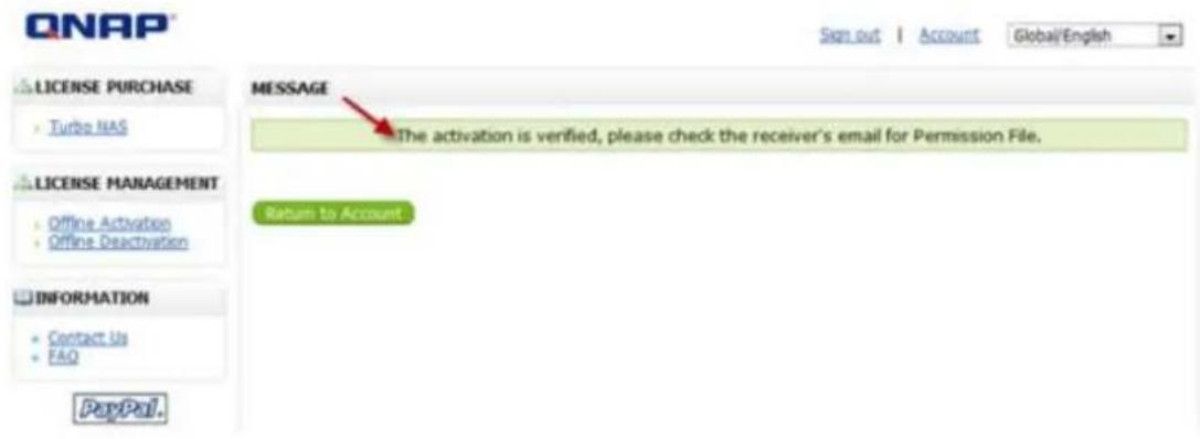
Step6. Please check the email and download the permission le. The permission le can only be used on the VioStor NVR with the UDI you specied. Please do not decompress the permission le.
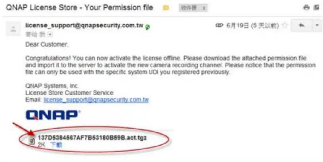
Step7. Please go back to the offline activation page on your VioStor NVR. You will need import the permission file to activate the license.
Step8. The license has been activated.
7.6.2 License Deactivation
Please select the "License deacvate" button to begin the process of deacvang a license. If your VioStor NVR is connected to the Internet, please select "Online deacvaon". If not, please select "Ofine deacvaon".
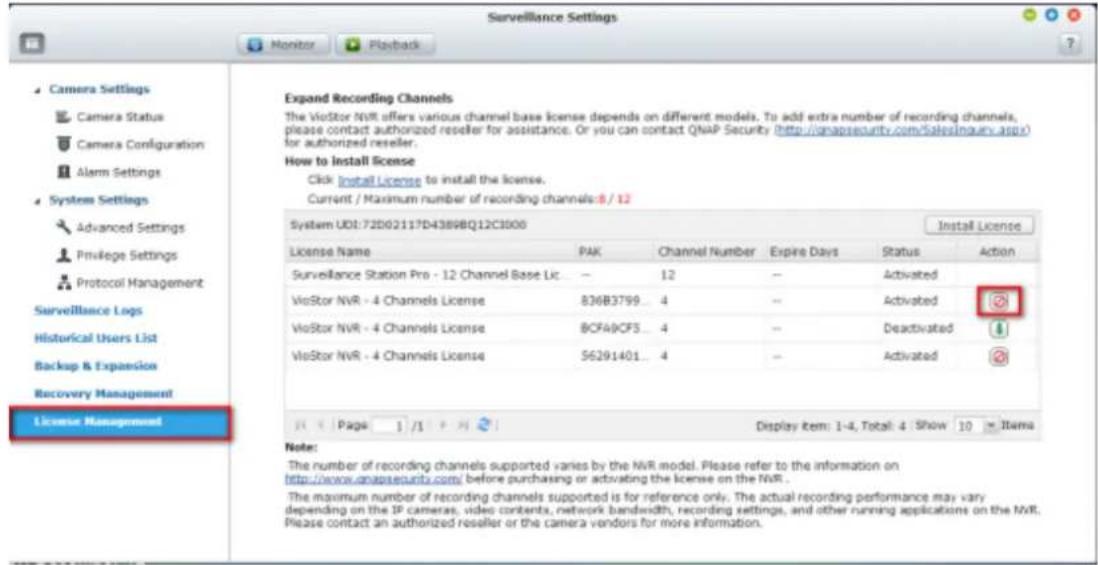
Online Deactivation
Step 1: Aer you press the "License deacvate" buon, you will be prompted to conrm that you want to deacvate the license.
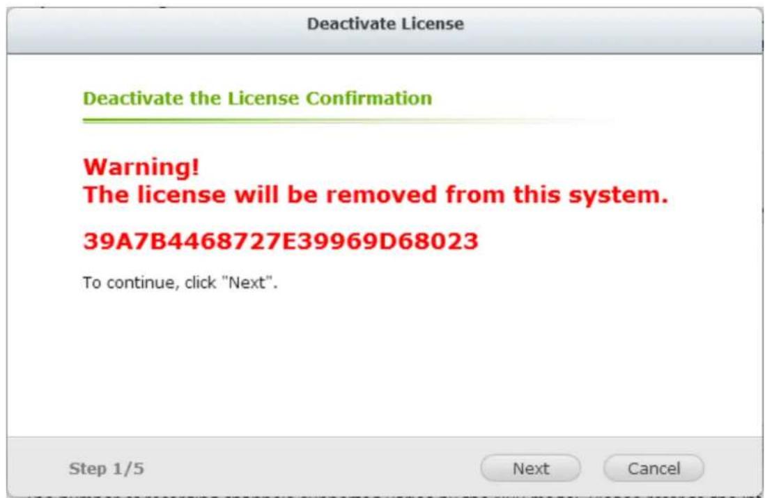
Step 2: Please select "Online Deacvaon".
Deactivate License
Deactivate the License Confirmation

Online Deactivation
Deactivate the license online. Make sure the system is connected to the Internet.
○ Offline Deactivation
Deactivate the license offline.
Step 2/5
Back
Next
Cancel
Step 3: The system will prompt you to conrm your choice to remove the license. If you are sure about deacvang the license, check "Yes, I want to remove the license from the system."
Deactivate License
Online Deactivation
Are you sure you want to remove the license from the system?
√ Yes, I want to remove the license from the system.
Step 4/5
Back
Next
Cancel
Step 4: The license has been deactivated. Please click [FINISH] buon to close the window.
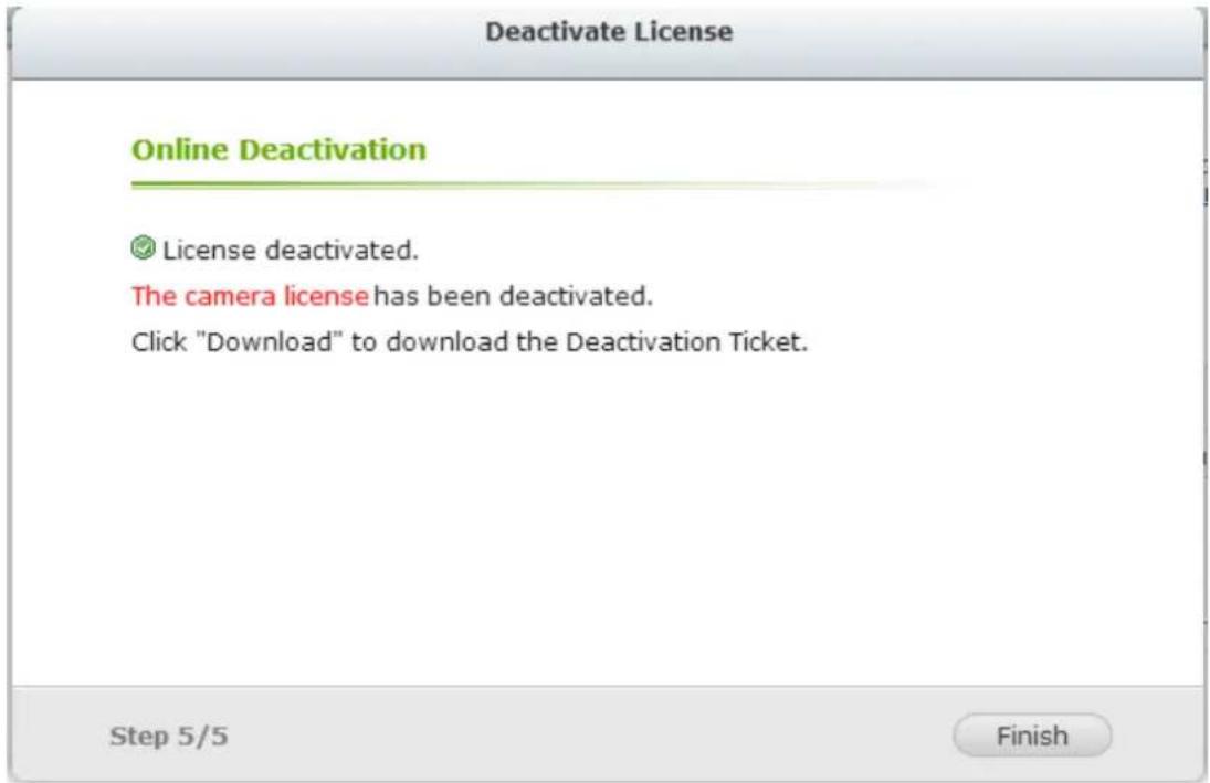
Step 5: And now you will see that the status of the license has changed to "Deacvated".
Expand Recording Channels
The VioStor NVR offers various channel base license depends on different models. To add extra number of recording channels, please contact authorized reseller for assistance. Or you can contact QNAP Security (http://gnapsecurity.com/SalesInquiry.aspx) for authorized reseller.
How to install license
Click Install License to install the license.
Current / Maximum number of recording channels: 4 / 12
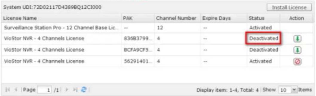
Note: If you want to transfer the License to another VioStor NVR, please download the "deacvaon cket" from the icon "" (under the "Acon" column). Then contact QNAP support for help.
Offline Deactivation
Step 1: Aer you press the "License deacvate" buon, you will be prompted to conrm that you want to deacvate the license.
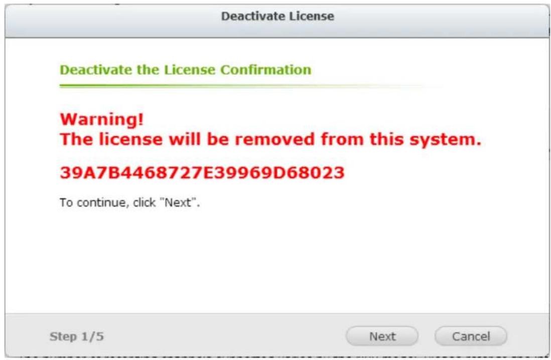
Step 2: Please select "Oine Deacvaon".
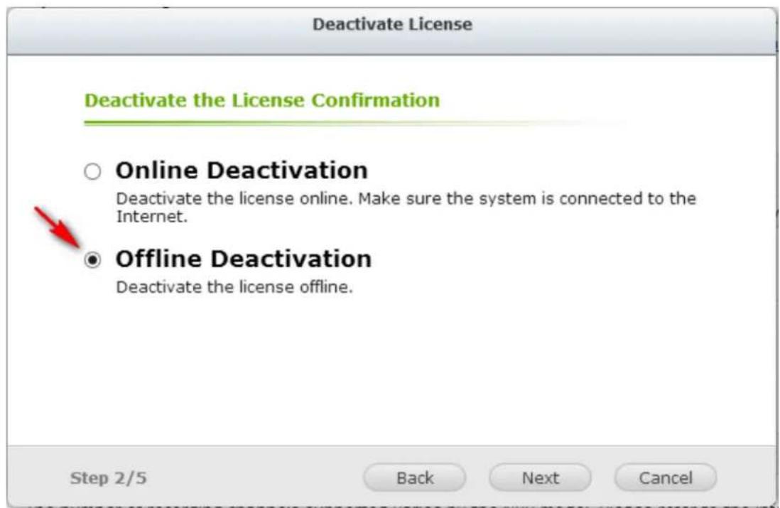
Step 3: Please read the instrucons carefully. Aer you deacvate the license on the system, you will need to download the deacvaon cket and visit the QNAP license store to complete the deacvaon. hp://license.qnap.com/deacvate.html
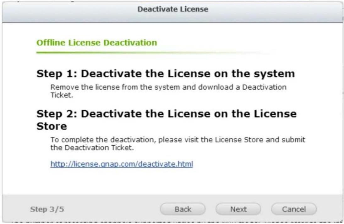
Step 4: The system will prompt you to conrm your choice to remove the license. If you are sure about deacvang the license, check "Yes, I want to remove the license from the system."
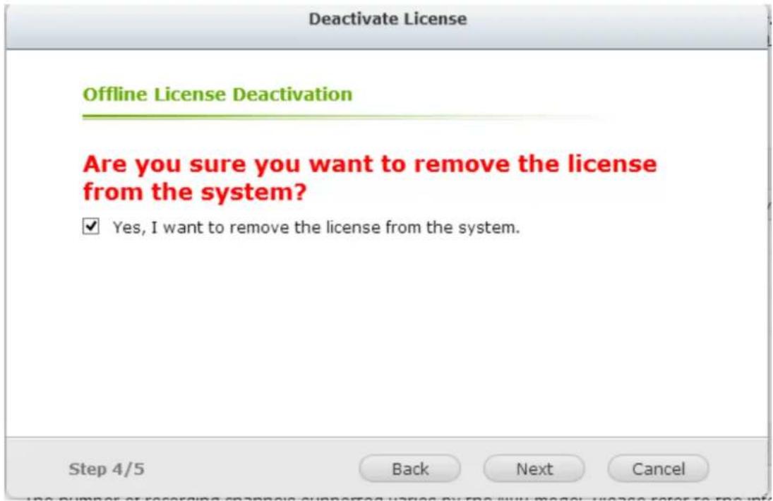
Step 5: The system will show that the license had been deactivated. Please download the deactivated cket from the column "Acon".
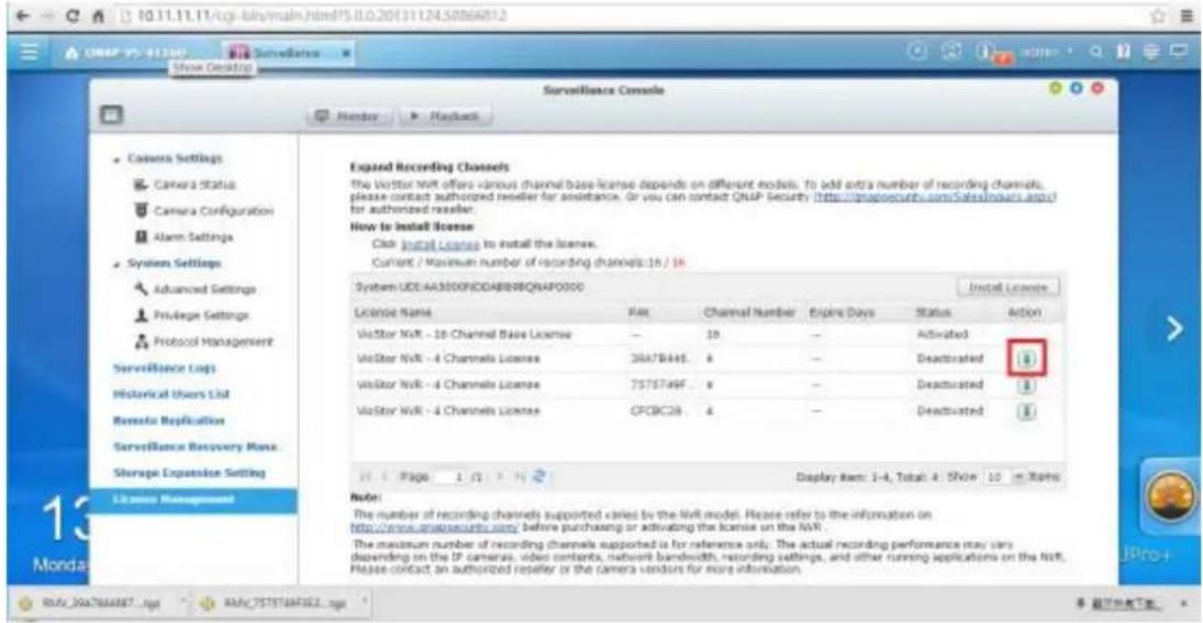
Step 6: Then please go to the QNAP license store, import the deacvaon cket and then enter the code in the box. Please click "Apply" aer you nish all these steps.
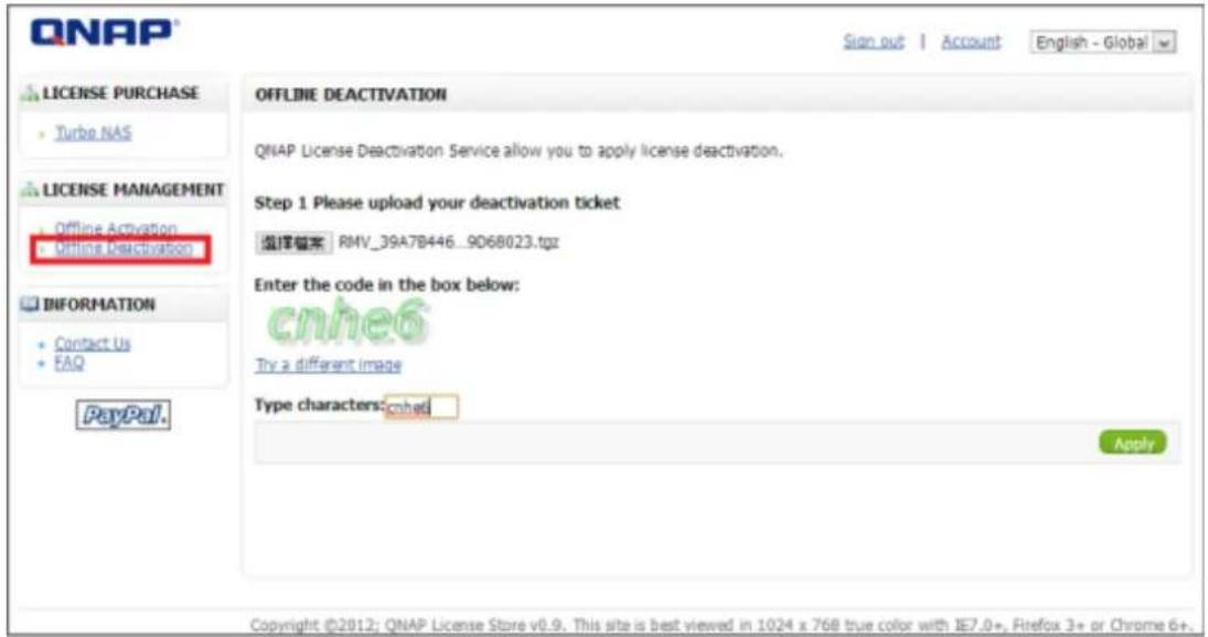
Step 7: The license store will show "License deactivated".
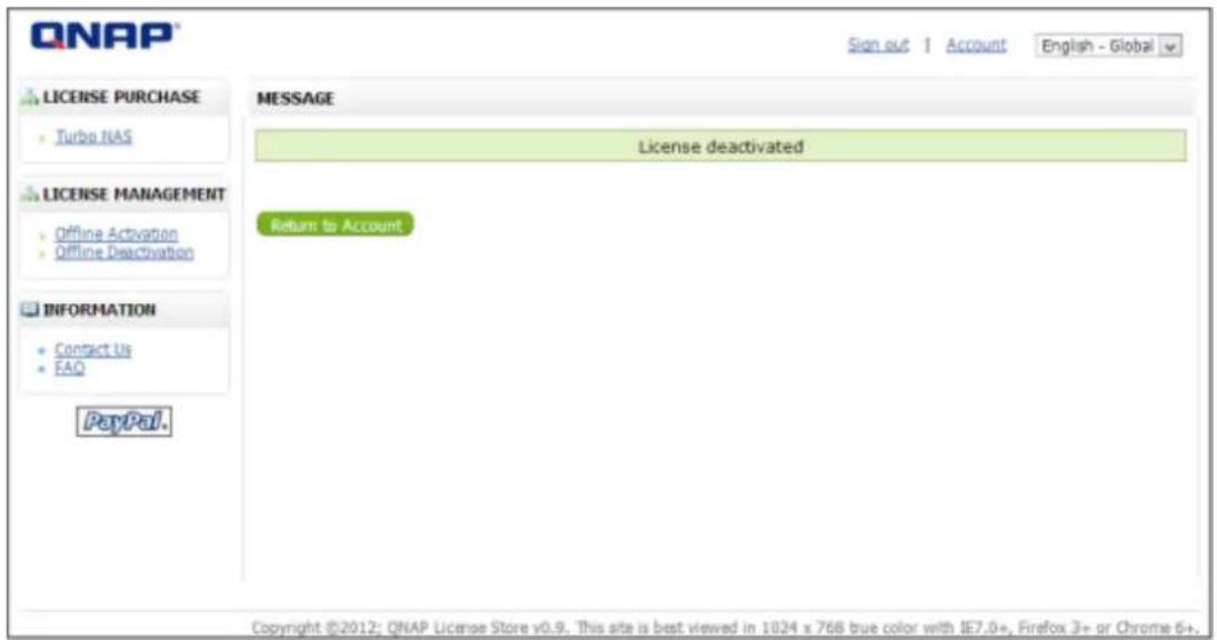
Note: If you want to transfer the License to another VioStor NVR, please download the "deacvaon cket" from the icon "" (under the "Acon" column). Then contact QNAP support for help.
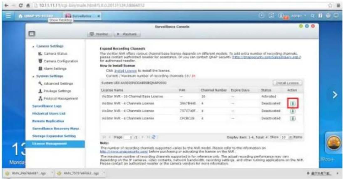
7.7 On-line Users List (Only for Upgrade from Previous
Version)
This page shows the informaon of the users before you upgraded to QVR 5.0, e.g. the user name, IP address, and login me.
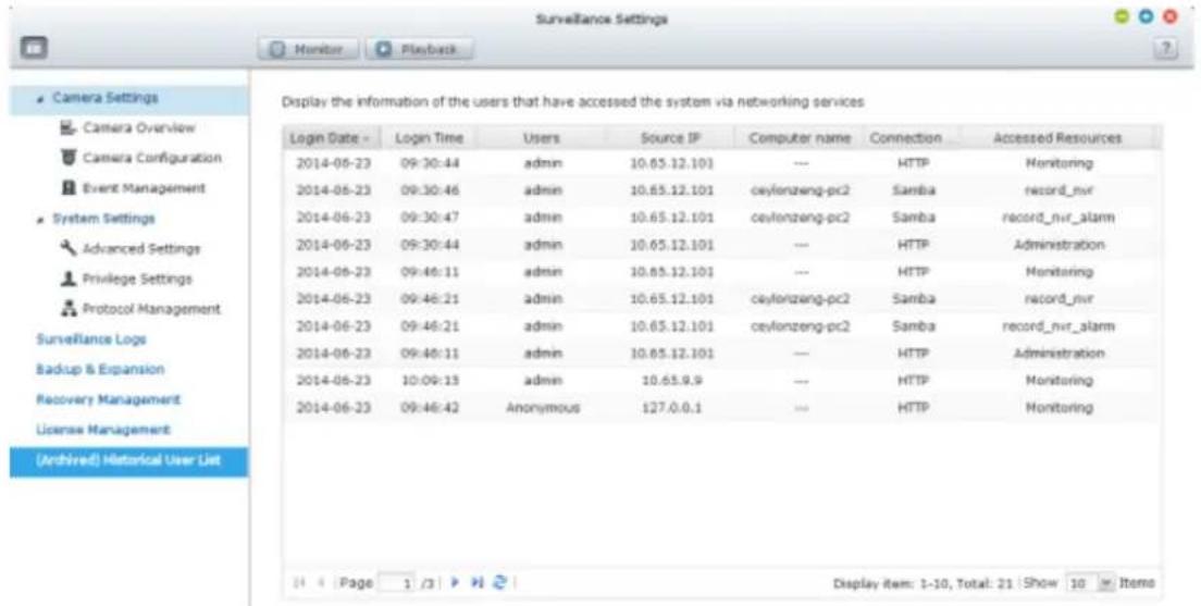
Please Note: The logs are currently only available in English.
8. Backup & Expansion
8.1 External Backup
The NVR supports instant and scheduled data backup between the internal disk volumes on the NVR and external USB storage devices. To use this feature, follow the steps below.
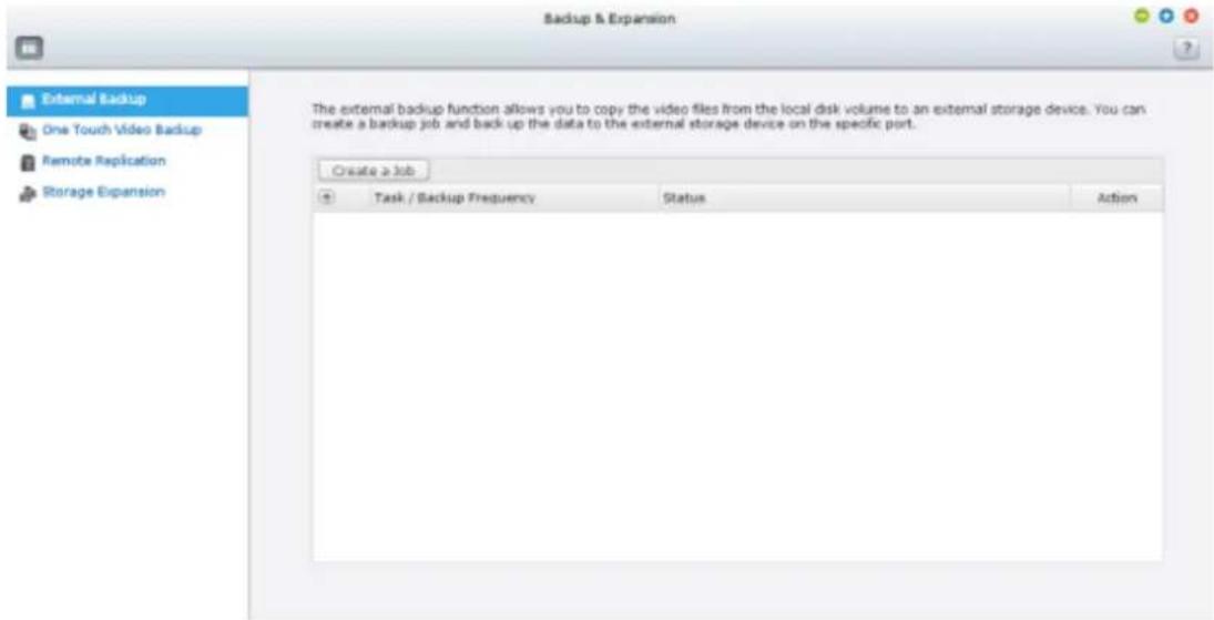
- Connect one or more external storage devices to the USB interfaces of the NVR.
- Click "Create a job".
- When the wizard is shown, read the instrucons carefully and click "Next".
Create a Job
Synchronization Job Wizard
This wizard helps you create a sync job through the following steps.
-
Connect to an external storage device.
-
Configure real-time or scheduled sync options.
Click "Next" to start.
Step 1/7
Next
Cancel
- Select the backup locaons.
A. Select an external disk volume* from the drop-down menu. The NVR supports EXT3, EXT4, FAT, NTFS, and HFS+ le systems. The general informaon of the storage device will be shown.
B. Click "Next".
- Congure the replicaon schedule.
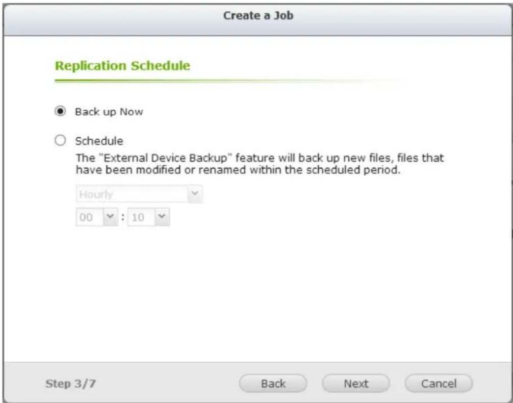
Choose between immediate backup and scheduled backup. The opons are:
A. Back up Now: Immediately copies les that are dierent from the source folder to the target folder.
B. Schedule: Copies les that are new, changed, and renamed from the source folder to the target folder according to the schedule.
- Hourly: Select the minute when an hourly backup should be executed, e.g. select 01 to execute the backup job every rst minute of an hour, 1:01, 2:01, 3:01...
- Daily: Specify the me when a daily backup should be executed, e.g. 02:02 every day.
• Weekly: Select a day of the week and the me when a weekly backup should be executed.
• Periodically: Enter the me interval in hour and minute that the backup job should be executed. The minimum me interval is 5 minutes.
C. Click "Next".
- If you choose "Back up Now" and click "Next," you can congregate the backup sengs as below.
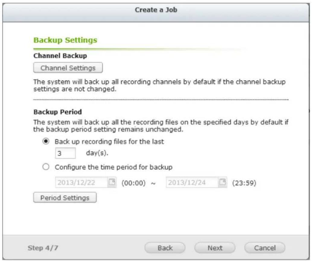
A. Congure backup channel.
If the backup channel sengs are not changed, the system will back up all recording channels by default.
You can click "Backup channel" to conjure the backup channels.
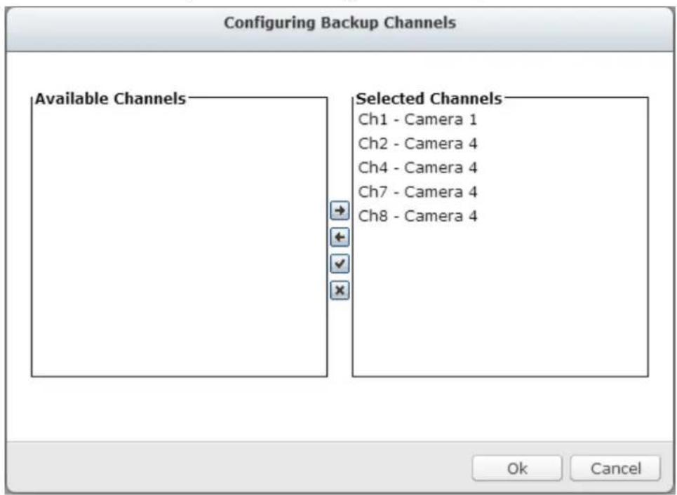
B. Congure backup duraon and les
If the backup duraon sengs are not changed, the system will back up all of the recording les on the specied days by default.
- Set the number of days that the latest recordings should be backed up. If 3 days are entered, the recordings of today, yesterday and the day before yesterday will be backed up.
• Or set the me period for backup.
- You can click "Backup duraon and les" to conjure the backup duraon and les.
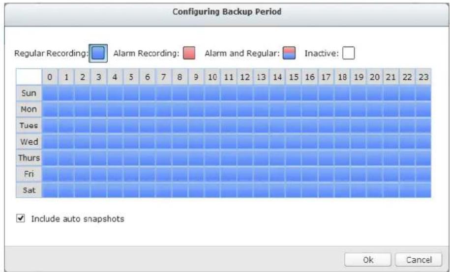
Enable "Include auto snapshots" to also copy the auto snapshot les when the recordings are congured to back up.
C. Click "Next".
- If you choose "Schedule," you can congregate the backup sengs as below.
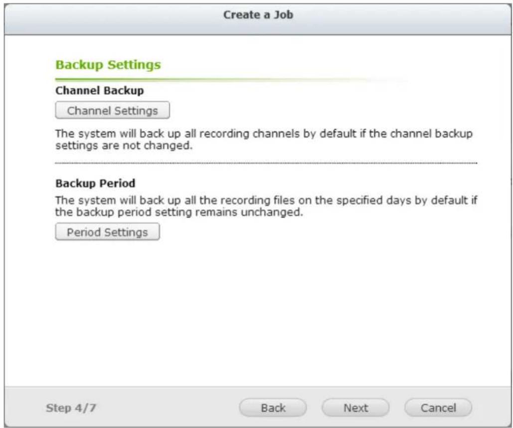
A. Congure backup channel.
If the backup channel sengs are not changed, the system will back up all of the recording channels by default.
You can click "Backup channel" to conjure backup channels.
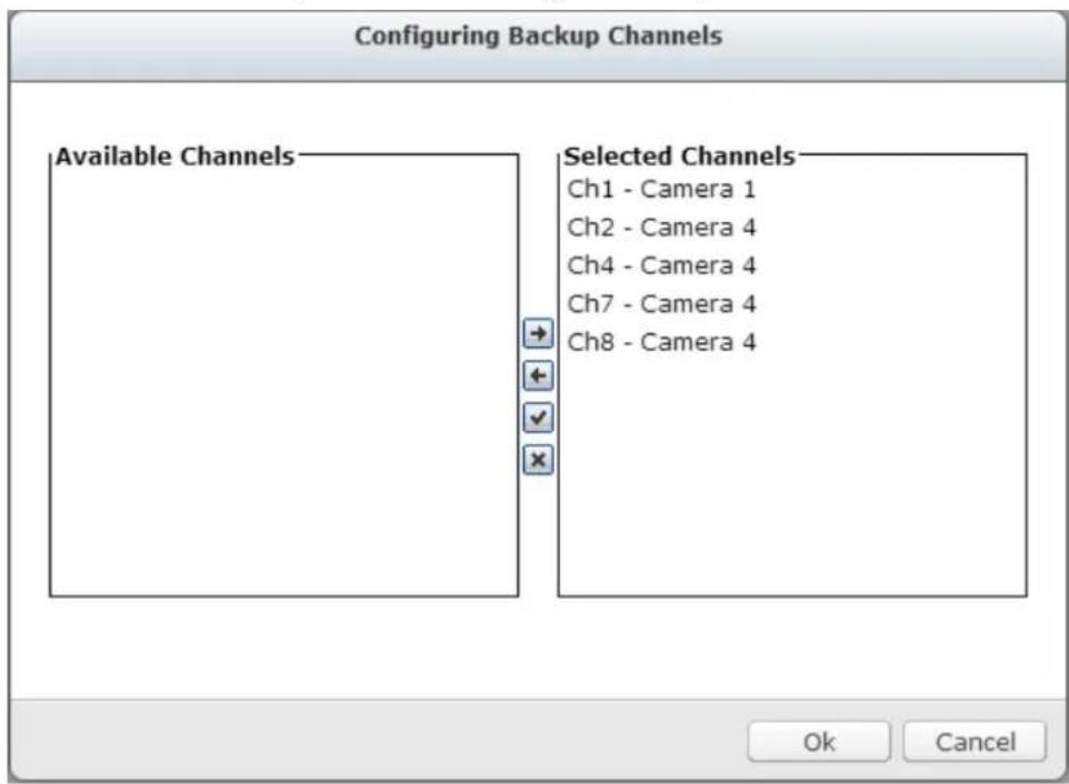
B. Congure backup duraon
If the backup duraon sengs are not changed, the system will back up all of the recording les on the specied days by default.
- You can click "Backup duraon and les" to conjure backup duraon and les
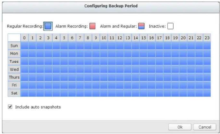
Enable "Include auto snapshots" to also copy the auto snapshot les when the recordings are congured to back up.
C. Click "Next".
- Advanced Settings include the ability to overwrite old recordings and to enable password protecon.
Advanced Settings
√ Overwrite the oldest recordings
√ Enable password protection
Confirm password
Step 4/7
Back
Next
Cancel
- Enter a name for the backup job. A job name supports up to 63 characters; it cannot start or end with a space. Click "Next".
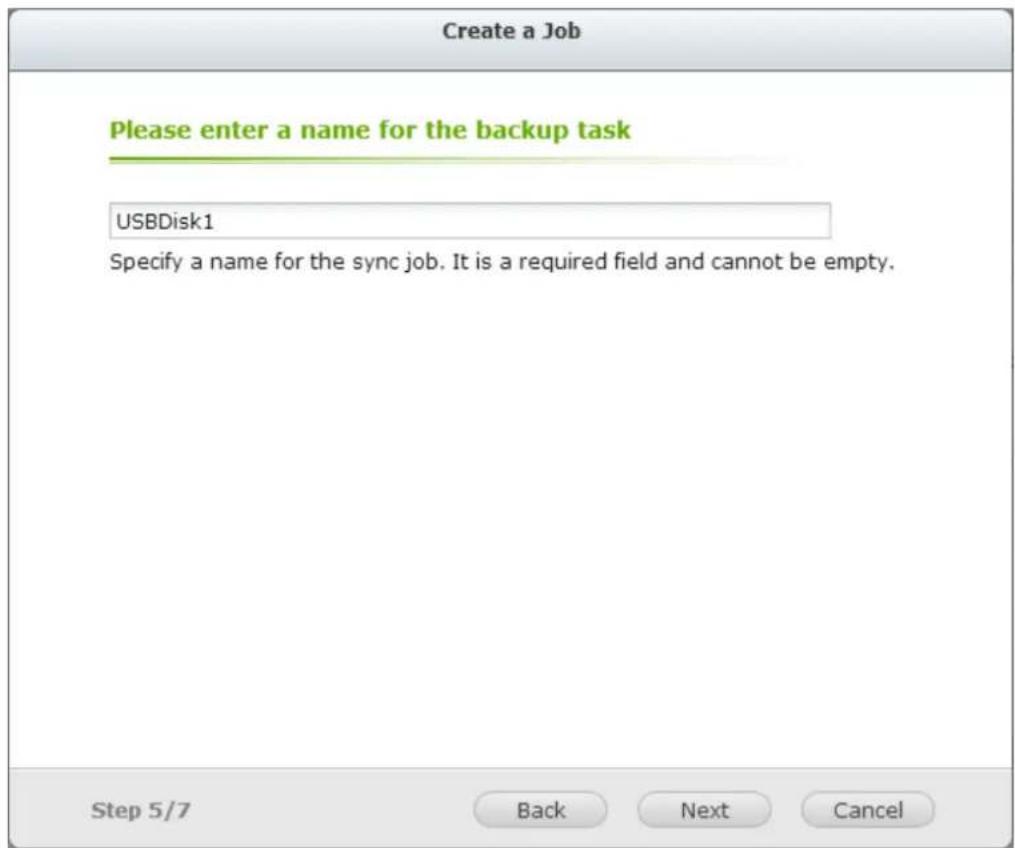
- Conrm the setngs and click "Next".
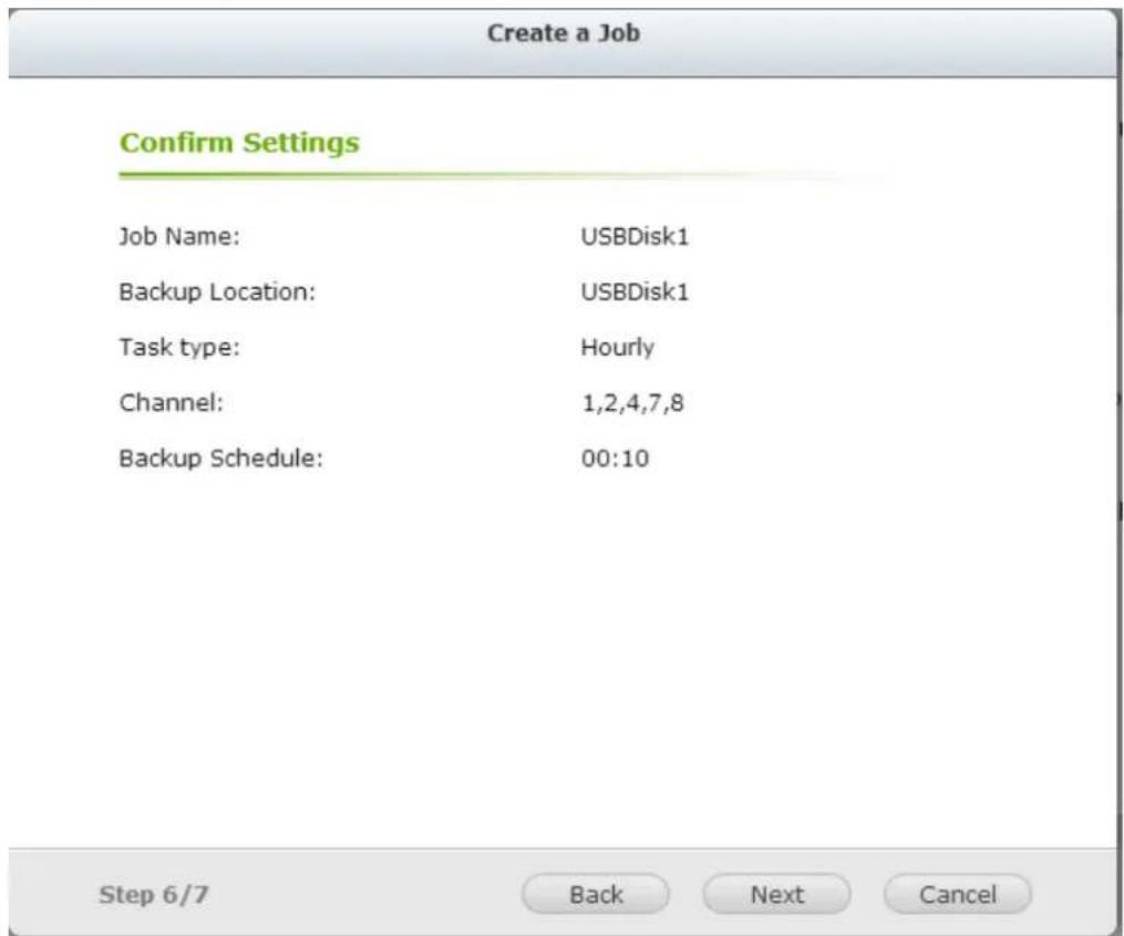
- Click "Finish" to exit the wizard.
8.2 One Touch Video Backup
This opon is valid only for series with a One Touch Video Backup buon.
Enable this opon to allow users to connect an external storage device to the front USB port and press the "One Touch Video Backup" buon to back up recording les.
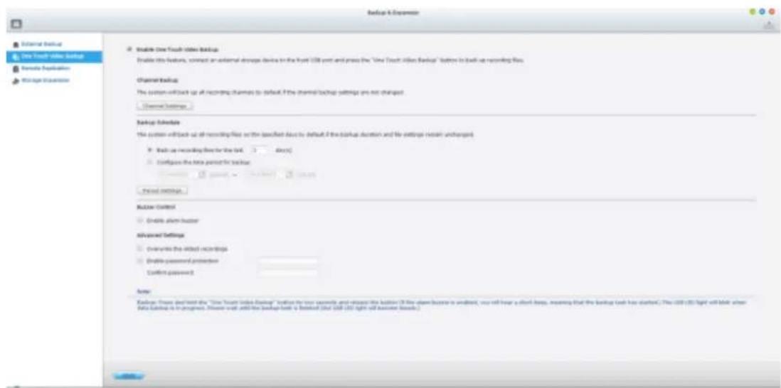
To use this funcon, please follow the steps below:
- Connect a USB storage device, for example, a USB disk drive to the front USB port of the NVR.
- Enable the opon "Enable One Touch Video Backup."
- Congure backup channel.
If the backup channel sengs are not changed, the system will back up all recording channels by default.
You can click "Backup channel" to conjure the backup channels.
Configuring Backup Channels


4. Congure backup duraon and les
If the backup duraon sengs are not changed, the system will back up all of the recording les on the specied days by default.
A. Set the number of days that the latest recordings should be backed up. If 3 days are entered, the recordings of today, yesterday and the day before yesterday will be backed up.
B. Or set the me period for backup.
C. You can click "Backup duraon and les" to conjure backup duraon and les.
Configuring Backup Period

√ Include auto snapshots in the specified period
Ok Cancel
Enable "Include auto snapshots" to also copy the auto snapshot les when the recordings are congured to back up.
- Advanced Settings include the ability to overwrite old recordings and to enable password protecon.
Advanced Settings
√ Overwrite the oldest recordings
√ Enable password protection
Confirm password
Step 4/7
Back
Next
Cancel
When "Enable password protecon" is applied, you will need to enter the
password to playback recording les via

-
Click "Apply".
-
Press and hold the video backup buon for 3 seconds and the NVR will immediately start copying the recording data to the USB device. If the USB device is recognized, the USB LED will glow blue. The USB LED will ash blue when the data is being copied. The LED will turn o aer the data has been copied. Then users can safely remove the device.
Note: Only USB devices with at least 10GB storage capacity are supported by this video backup funcon.
Buzzer Control
Aer enabling the alarm buzzer, if you hear one short beep, it means 'Backup has started.
8.3 Remote Replication
Use the remote replicaon feature to copy the recording data of the local NVR to a remote QNAP network aached storage (NAS). The remote QNAP NAS is hereaer referred to as 'the remote storage device'.
Note: Before using this funcon, make sure the Microso networking service of the remote storage device is enabled, and the corresponding path and user access right has been correctly congured.
- Login to the QVR desktop and go to 'Backup & Expansion' > 'Remote Replicaon'.
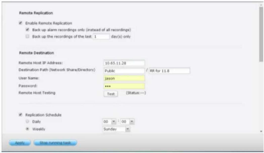
- Enable remote replicaon (supports mulple choices)

In the above example, the NVR only copies the alarm recording data of the latest 3 days to the remote storage device.
- Select 'Enable remote replicaon' to acvate this feature. The NVR will execute an automac backup of the recording data to the remote storage device according to the sengs.
- Select 'Back up alarm recordings only (instead of all recordings)', the NVR will only copy the alarm recording data to the remote storage device. If this option is unselected, the NVR will back up all of the recording data to the remote storage device.
- Select 'Back up the recordings of the latest...day(s) only' and enter the number of days, the NVR will back up the latest recording data to the remote storage device automacally according to the sengs. If this opon is unselected, the NVR will copy all of the recording data to the remote storage device.
3. Congure the remote storage server
Remote Destination
Remote Host IP Address:
Destination Path (Network Share/Directory)
User Name:
Password:
Remote Host Testing
Enter the IP address, path, user name and password of the remote storage device.
Note: It is recommended to execute the 'Remote host tesng' funcon to verify the conncon to the remote storage device is successful.
4. Congure the remote replicaon schedule
Remote Destination
Remote Host IP Address:
Destination Path (Network Share/Directory)
User Name:
Password:
Remote Host Testing
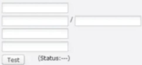
For example, to enable the NVR to copy the recording data automacally to the remote storage device at 01:15 every Monday, please do the following: Select 'Replicaon Schedule', select 'Weekly', enter 01 Hour: 15 minute, and select 'Monday'.
5. Select the backup opons
Replication Now
☐ Overwrite the oldest recordings when the available storage on the remote host is less than 4GB
☐ Perform mirroring replication by deleting extra files on the remote destination
Note: When remote replication is in process, the recording performance will be decreased
- Select 'Replicaon Now', the NVR will back up the recording data to the remote storage device immediately.
- Select 'Overwrite the oldest recordings when the available storage on the remote host is less than 4GB'; the NVR will overwrite the oldest recording data when the free space on the server is less than 4GB.
- Select 'Perform mirroring replicaon by deleng extra les on the remote replicaon', the NVR will synchronize the recording data between itself and the remote storage device and delete any extra les on the remote storage device.
When the above opons are all selected and remote replicaon is executed, the NVR will do the following:
i. The NVR checks if there are les on the remote storage device that are dierent from the local source. If yes, the dierenated les will be deleted.
ii. Next, the NVR checks the free space of remote storage device. If the free space is larger than 4GB, the remote replicaon will be executed immediately.
iii. If the free space of the remote storage device is less than 4GB, the NVR will overwrite the recording data of the oldest day and then executes the remote replicaon.
- The NVR displays the latest 10 remote replicaon records.
| Start Time - | Finish Time | Replicated Data Size | Status |
| 2014-06-15 00:00... | 2014-06-15 02:17... | 801.3 MByte(s) | Failed (Remote access error) |
| 2014-06-12 21:34... | 2014-06-14 00:04... | 13.37 GByte(s) | Failed (Remote access error) |
| 2014-06-05 16:00... | 2014-06-06 11:16... | 13.98 GByte(s) | Failed (Remote access error) |
| 2014-05-26 00:28... | 2014-05-26 06:33... | 3.13 GByte(s) | Failed (Remote access error) |
| 2014-05-19 00:00... | 2014-05-21 11:53... | 37.09 GByte(s) | Failed (Remote access error) |
| 2014-05-12 00:00... | 2014-05-17 11:37... | 79.05 GByte(s) | Failed (Remote access error) |
| 2014-05-05 00:00... | 2014-05-05 13:35... | 8.20 GByte(s) | Failed (Remote access error) |
| 2014-04-29 15:38... | 2014-04-29 20:57... | 3.98 GByte(s) | Aborted (The remote replication was cancelled) |
| 2014-04-26 23:43... | 2014-04-27 15:01... | 7.16 GByte(s) | Failed (Remote access error) |
In the above example:
- When the status is shown as 'Failed (Remote access error)': Check to see if the remote storage device is running and if the network sengs are correct.
- When the status is shown as 'Failed (An internal error occurred)': Check the hard drive status of the NVR and view the Event Logs.
Note: The me required by the NVR to replicate the data to the remote storage device varies depending on the network environment. If the remote replicaon takes too long, some recording les may be overwritten by the NVR. To avoid this, it is recommended to refer to the status messages to analyze the me required for the remote replicaon and adjust the replicaon schedule accordingly.
8.4 Storage Expansion
Without a doubt, storage plays a significant role in the eld of digital surveillance. However, users everywhere are facing the challenge of storage capacity for long-term recording. Now, QNAP Security has introduced the storage expansion feature to eliminate this problem. Making the right storage decision with regard to storage expansion is truly important to save money & me for all users. The various QNAP Turbo NAS models are the soluon that expands on the storage capacity of the NVR to save more recording les. The storage expansion can provide up to 64TB (16-bay model) additional space per channel, totaling more than 200TB. Integraon of both QNAP devices can help users easily save a significant amount of recording les.
Key features:
- Addressing user needs: Users can expand their storage capacity based on their needs.
- Reducing expense: This is a cost-eecve choice for expanding storage capacity.
- Highly scalable for future storage expansion.
Limitaons and Restricons:
- Currently, Storage Expansion is only supported by the VioStor Pro(+) series and QNAP x86-based NAS models (with rmware version v4.0.2 and above), and they are required to be set on the same LAN.
- A gigabit switch is required for this applicaon.
- For NVR and NAS servers located on the same subnet, please always use stac IP addresses and the same subnet mask.
- Modicaon on storage expansion related sengs is not supported on local display.
- The le moving process between the NVR and NAS will be completed even if it is suddenly interrupted (for example, the desnaon folder is deleted). For example, the cache count is set to six hours. The desnaon is changed to none in the middle of the processing. When this happens, the NVR will sll move recording les to the NAS unl the enre process is nished.
Note:
In order to ensure that Storage Expansion can be executed during the recording
process, please be advised to esmate the limitaon on network throughput for specific VioStor NVR series.
The following is suggested limitaon of the network throughput for specic NVR models:
VS-8100 Pro+/8100U-RP Pro (+)/12100U-RP Pro (+) series: 360 Mbps.
VS-2100 Pro+/4100 Pro+/6100 Pro+ series: 160 Mbps.
VS-2000 Pro/4000 Pro/6000 Pro series: 90 Mbps.
How to congregate Storage Expansion?
Step 1:
Install the StorageExpansion QPKG on the NAS
Note: Please visit our download center to download the QPKG. Before installing the QPKG package, please make sure the QPKG is correct, read the instrucons carefully and back up all the important data on the NAS.
1. Download
and unzip the StorageExpansion package.
To install the QPKG, please click "Browse" to select the correct QPKG le and click "INSTALL".
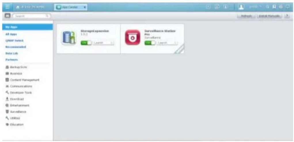
Disable: disable the StorageExpansion QPKG.
Remove: remove the StorageExpansion QPKG.
2. Click the link
to connect to the webpage and congure the sengs.
Check available NVRs on the list and their status on this page.
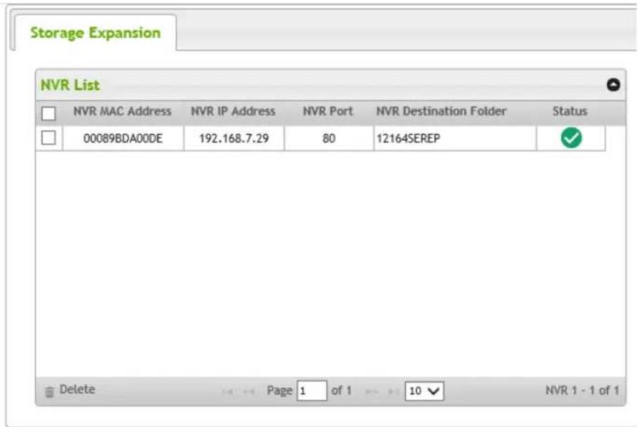
| Status | Description |
| Connection Success | |
| Failure of storage expansion due to incorrect storage expansion assignments (please check your setting on the storage expansion page.) | |
| Failure of storage expansion because Subnet Mask setting of NAS and NVR should be the same. | |
| Failure of storage expansion as the HVR (MAC address) is changed. | |
| Failure of storage expansion because no NVR is found. |
Note: The status of an NVR will become aer storage expansion assignment is completed.
Step2:
Please make sure that the StorageExpansion QPKG has been installed on the NAS and enable Storage Expansion.
1. Go to
"Camera Seng" → "Storage Expansion" to congure relevant setngs on the page.

2. Click
"Overview" then the "Add" button.
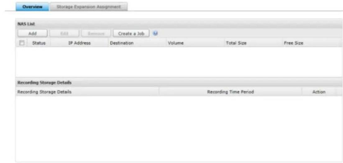
Please enter the IP, port, username, password, desnaon, volume and cache count for the NAS.
Add NAS
NAS IP Address:
Port:
User Name:
Password:
Destination:
Volume:
Backup buffer:
8080
Select a disk volume
6
Apply
Cancel
Note:
Desnaon Folder: The folder created on the NAS to save recording les.
Volume: The volume assigned for storage expansion.
Backup buer: The me period for recording les to be moved to the NAS. The range is from 2-48 hours.
3. Cong NAS:
Modify NAS sengs on this page.
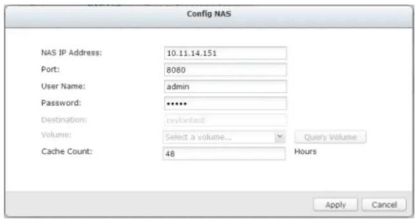
4. Click "Storage
Expansion Assignment" to choose a NAS as the storage unit for each channel.

| Storage Expansion Assignment | ||||
| Channel | Camera Name | NAS IP Address | Destination | Action |
| 1 | 1. Sony P1 | 10.65.11.27 | sin9527110 | |
| 2 | 2. Sony CS11 | 10.65.11.27 | sin9527110 | |
| 3 | 3. Sony CS10 | 10.65.11.27 | sin9527110 | |
| 4 | 4. Sony Z20 | 10.65.11.27 | sin9527110 | |
| 5 | 5. Sony EM600 | 10.65.11.27 | sin9527110 | |
| 6 | 6. Sony CS50 | 10.65.11.27 | sin9527110 | |
| 7 | 7. Sony P5 | 10.65.11.27 | sin9527110 | |
| 8 | 8. Sony RZ2S | 10.65.11.27 | sin9527110 | |
| 9 | 9. Sony RZ30 | 10.65.11.27 | sin9527110 | |
| 10 | 10. Sony RZ50 | 10.65.11.27 | sin9527110 | |
| 11 | 11. Sony RX550 | 10.65.11.27 | sin9527110 | |
| 12 | 12. Sony SNC-DF40 | 10.65.11.27 | sin9527110 | |
Review all of the congured sengs and recording storage details under "Overview".
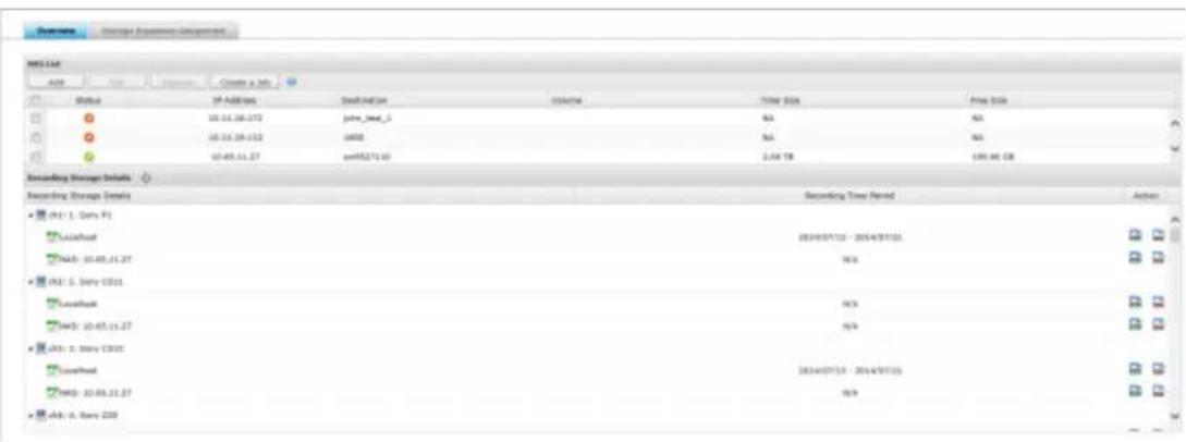
9.1.1 General Settings
System Administration
Enter the name of the NVR. The NVR name supports maximum 14 characters and can be a combinaon of the alphabets (a-z, A-Z), numbers (0-9), and dash (-). Space (), period (.), or pure number are not allowed.
Enter a port number for the system management. The default port is 80. If you are not sure about this seng, use the default port number.
Enable Secure Connecon (SSL)
To allow the users to connect the NVR by HTTPS, turn on secure conncon (SSL) and enter the port number. If the opon “Force secure conncon (SSL) only” is turned on, the users can only connect to the web administraon page by HTTPS conncon.
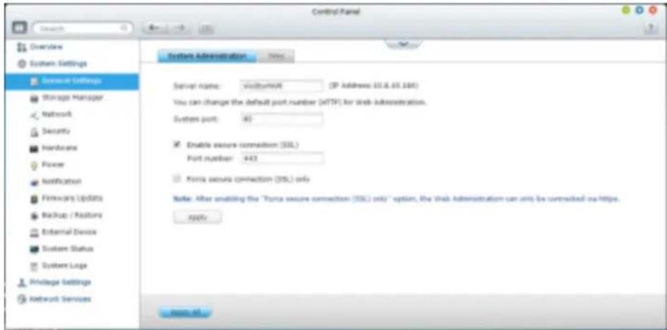
Time
Adjust the date, me, and me zone according to the locaon of the NVR. If the sengs are incorrect, the following problems may occur:
The display time of the recordings will be incorrect.
The time of the event log displayed will be inconsistent with the actual time when an action occurs.
Synchronize with an Internet time server automatically
Turn on this option to synchronize the date and time of the NVR automatically with an NTP (Network Time Protocol) server. Enter the IP address or domain name of the NTP server, for example, time.nist.gov, time.windows.com. Then enter the time interval for synchronization. This option can be used only when the NVR is connected to the Internet.
Disable RTC synchronization
Disable this option to enable RTC synchronization.
Note: A real-time clock (RTC) is a computer clock (most often in the form of an integrated circuit) that keeps track of the current time.
Set the server time the same as your computer time
To synchronize the time of the NVR with the computer time, click "Update" next to this option.

9.1.2 Storage Manager
Volume Management
This page shows the model, size, and current status of the hard drives on the NVR.
You can format and check the hard drives, and scan the bad blocks on the hard drives.
When the hard drives have been formaed, the NVR will create the following default share folders:
mp4: The shared folder for MP4 Recordings App.
record_export: The shared folder for Recording Export Pro APP.
record_nvr: The default shared folder for regular recording les.
record_nvr_alarm: The default shared folder for alarm recording les.
snapshot: The default shared folder for auto snapshot.
Note: The default shared folders of the NVR are created on the rst disk volume and the directory cannot be changed.
| Disk Conguraon | Applied NVR Models |
| Single disk volume | All models |
| RAID 0 | 2-drive models or above |
| RAID 1, JBOD (just a bunch of disks) | 2-drive models or above |
| RAID 5, RAID 6, RAID 5+hot spare | 4-drive models or above |
| RAID 6+hot spare | 5-drive models or above |
| RAID 10 | 4-drive models or above |
| RAID 10+hot spare | 5-drive models or above |
| Single Disk VolumeEach hard drive is used as a standalone disk. If a hard drive is damaged, all the data will be lost. | |
| JBOD (Just a bunch of disks)JBOD is a collecon of hard drives that does not oer any RAID protecon. The data are wrien to the physical disks sequenally. The total storage capacity is equal to the sum of the capacity of all member hard drives. | 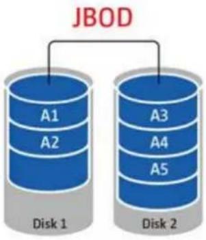 |
| RAID 0 Striping Disk VolumeRAID 0 (striping disk) combines 2 or more hard drives into one larger volume. The data is wrien to the hard drive without any parity informaon and no redundancy is oered.The total storage capacity of a RAID 0 disk volume is equal to | 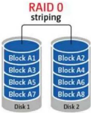 |
| the sum of the capacity of all member hard drives. | |
| RAID 1 Mirroring Disk VolumeRAID 1 duplicates the data between two hard drives to provide disk mirroring. To create a RAID 1 array, a minimum of 2 hard drives are required.The storage capacity of a RAID 1 disk volume is equal to the size of the smallest hard drive. | 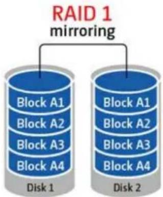 |
| RAID 5 Disk VolumeThe data are striped across all the hard drives in a RAID 5 array.The parity informaon is distributed and stored across each hard drive. If a member hard drive fails, the array enters degraded mode. Aer installing a new hard drive to replace the failed one, the data can be rebuilt from other member drives that contain the parity informaon.To create a RAID 5 disk volume, a minimum of 3 hard drives are required.The storage capacity of a RAID 5 array is equal to (N-1) * (size of smallest hard drive). N is the number of hard drives in the array. | 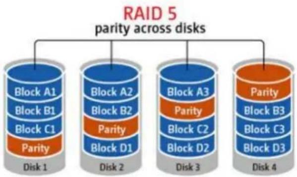 |
| RAID 6 Disk VolumeThe data are striped across all the hard drives in a RAID 6 array.RAID 6 diers from RAID 5 that a second set of parity informaon is stored across the member drives in the array. It tolerates failure of two hard drives.To create a RAID 6 disk volume, a minimum of 4 hard drives are required. The storage capacity of a RAID 6 array is equal to (N-2) * (size of smallest hard drive). N is the number of hard drives in the array. | 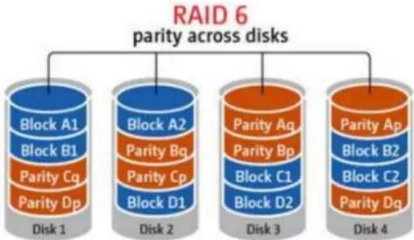 |
| RAID 10 Disk VolumeRAID 10 combines four or more disks in a way that protects data against loss of non-adjacent disks. It provides security by mirroring all data on a secondary set of disks while using striping across each set of disks to speed up data transfers.RAID 10 requires an even number of hard drives (minimum 4 hard drives). The storage capacity of RAID 10 disk volume is equal to (size of the smallest capacity disk in the array) * N/2. N is the number of hard drives in the volume. | 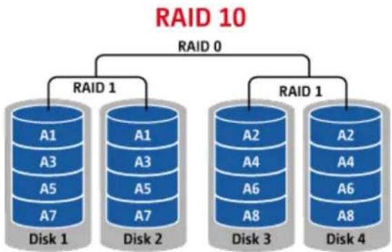 |
RAID Management
You can perform online RAID capacity expansion (RAID 1, 5, 6, 10) and online RAID level migraon (single disk, RAID 1, 5, 10), add a hard drive member to a RAID 5, 6, or 10 conguraon, conjure a spare hard drive (RAID 5, 6, 10) with the data retained, enable Bitmap, recover a RAID conguraon, and set a global spare on this page.
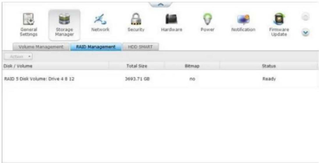
To expand the storage capacity of a RAID 10 volume, you can perform online RAID capacity expansion or add an even number of hard disk drives to the volume.
Expand Capacity (Online RAID Capacity Expansion)
Scenario
You bought three 250GB hard drives for initial setup of a NVR and congured RAID 5 disk conguraon with the three hard drives.
A half year later, the data size of the department has largely increased to 1.5TB. In other words, the storage capacity of the NVR is running out of use. At the same me, the price of 1TB hard drives has dropped to a large extent.
Operaon procedure
In "Storage Manager" > "RAID Management", select the disk volume for expansion and click "Expand Capacity".
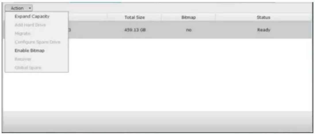
Click "Change" for the rst hard drive to be replaced. Follow the instrucons to proceed.

Tip: Aer replacing the hard drive, the descripon eld shows "You can replace this drive". This means you can replace the hard drive to a larger one or skip this step if the hard drives have been replaced already.

Cauon: When the hard drive synchronizaon is in process, do NOT turn o the NVR or plug in or unplug the hard disk drives.
When the descripon displays "Please remove this drive", remove the hard drive from the NVR. Wait for the NVR to beep twice aer removing the hard drive.
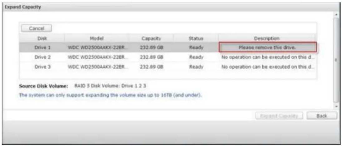
When the descripon displays "Please insert the new drive", plug in the new hard drive to the drive slot.
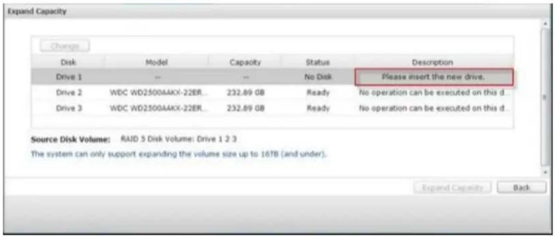
Aer plugging in the hard drive, wait for the NVR to beep. The system will start rebuilding.

Aer rebuilding has completed, repeat the steps above to replace other hard drives.
Aer changing the hard drives and disk rebuilding has completed, click "Expand Capacity" to execute RAID capacity expansion.
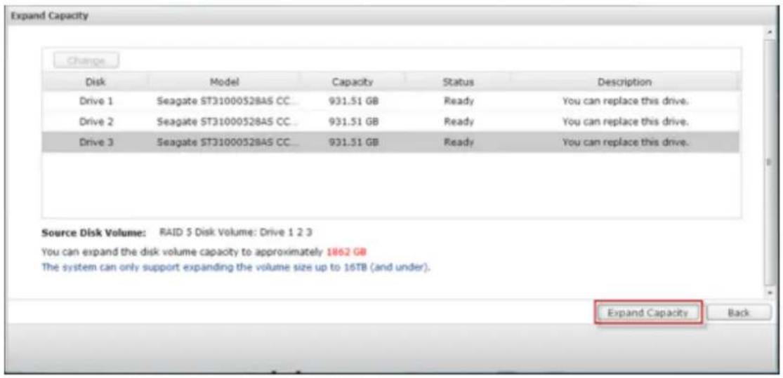
Click "OK" to proceed.
The NVR beeps and starts to expand the capacity.
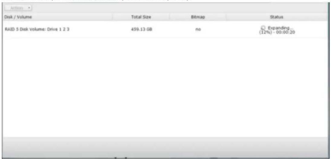
The process may take from hours to tens of hours to nish depending on the drive size. Please wait paently for the process to nish. Do NOT turn o the power of the NVR.
Aer RAID capacity expansion has nished, the new capacity is shown and the status is "Ready". You can start to use the NVR. (In the example you have 1.8TB logical volume.)
Tip: If the descripon sll shows "You can replace this hard drive" and the status of the drive volume says "Ready", it means the RAID volume is sll expandable.
Migrate (Online RAID Level Migraon)
During the initial setup of the NVR, you bought a 250GB hard drive and congured it as single disk.
Aer a period of me, more and more important recordings are saved on the NVR.
There is a rising concern for hard drive damage and data loss. Therefore, you planned to upgrade the disk conguraon to RAID 5.
You can install one hard drive for seng up the NVR and upgrade the RAID level of the NVR with online RAID level migraon in the future. The migraon process can be done without turning o the NVR. All the data will be retained.
You can do the following with online RAID level migraon:
• Migrate the system from single disk to RAID 1, RAID 5, RAID 6 or RAID 10
• Migrate the system from RAID 1 to RAID 5, RAID 6 or RAID 10
• Migrate the system from RAID 5 with 3 hard drives to RAID 6
You need to:
• Prepare a hard drive of the same or larger capacity as an exisng drive in the RAID conguraon.
- Execute RAID level migraon (migrate the system from single disk mode to RAID 5 with 4 hard drives).
Go to "Storage Manager" > "Volume Management". The current disk volume conguraon displayed on the page is single disk (the capacity is 250GB).
Plug in the new 250GB hard drives to drive slots 2 and 3 of NVR. The NVR will detect the new hard drives. The status of the new hard drives is "Unmounted".
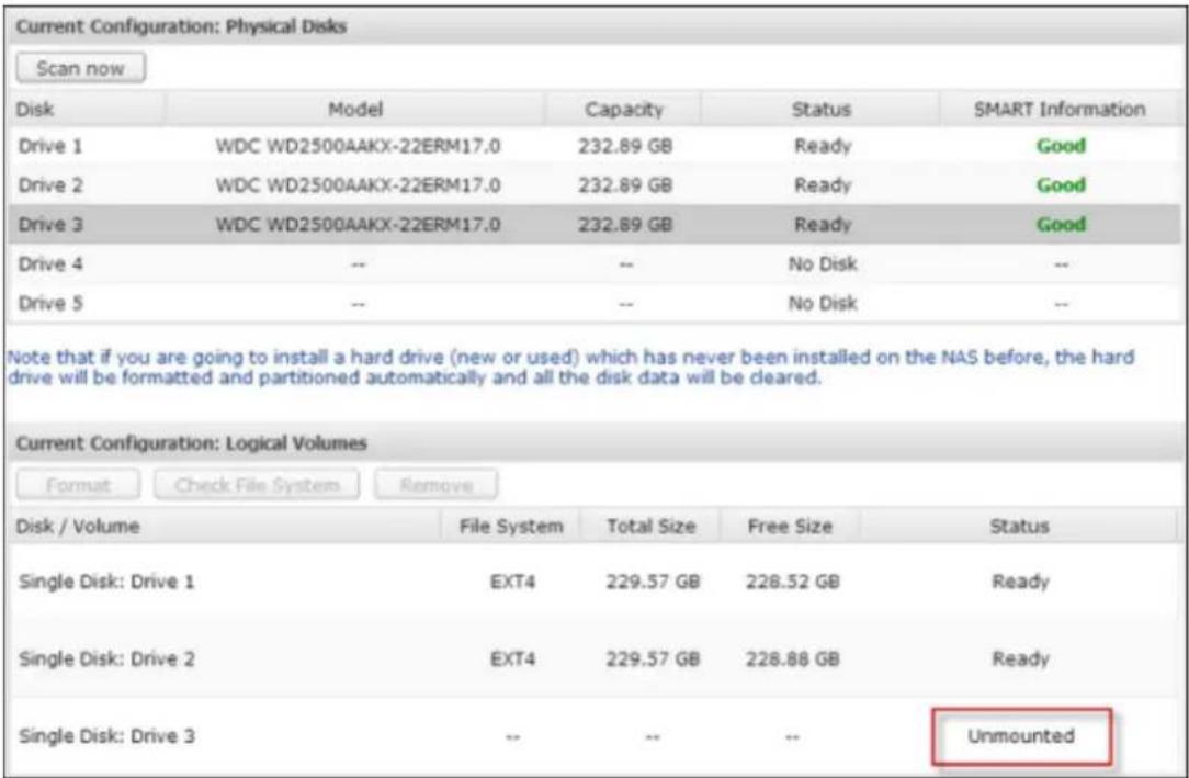
Go to "Storage Manager" > "RAID Management", click "Migrate" from the "Acon."
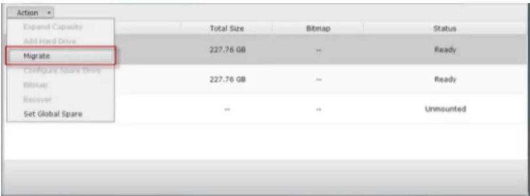
Select one or more available drives and the migraon method. The drive capacity aer migraon is shown. Click "Migrate".
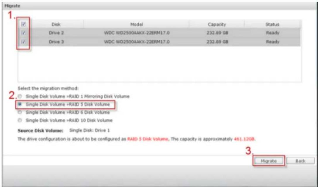
Note that all the data on the selected hard drive will be cleared. Click "OK" to conrm.
When migraon is in process, the required me and total drive capacity aer migraon are shown in the descripon eld.
The NVR will enter “Read only” mode when migraon is in process during 11%–49% to assure the data of the RAID conguraon will be consistent aer RAID migraon completes.
Aer migraon completes, the new drive conguraon (RAID 5) is shown and the status is Ready. You can start to use the new drive conguraon.
The process may take from hours to tens of hours to nish depending on the hard drive size. You can connect to the web page of the NVR to check the status later.
Use Online RAID Capacity Expansion and Online RAID Level Migraon
Add a hard drive
Follow the steps below to add a hard drive member to a RAID 5 or RAID 6 disk conguraon.
- Make sure the status of the RAID 5 or RAID 6 conguraon is "Ready".
- Install a hard drive on the NVR. If you have a hard drive which has already been
formaed as single disk volume on the NVR, you can add this hard drive to the RAID 5 or RAID 6 conguraon. You are recommended to use hard disk drives of the same storage capacity for the RAID conguraon.
Select the RAID 5 or RAID 6 conguraon on the "RAID Management" page and
- click "Add Hard Drive".
Select the new hard drive member. The total drive capacity aer adding the
- drive will be shown. Click "Add Hard Drive."
All the data on the new hard drive member will be deleted during this process.
The data on the original RAID 5 or RAID 6 conguraon will be retained. Click
- "OK". The NVR will beep twice.
To add hard drives member to a RAID 10 disk volume, repeat the above steps. Note that you need to add an even number of hard disk drives to a RAID 10 volume. The storage capacity of the RAID 10 volume will increase upon successful conguraon.
This process may take a few hours to tens of hours to complete depending on the number and the size of the hard drive. Please wait paently for the process to nish. Do NOT turn o the NVR during this process. You can use a RAID conguraon of larger capacity aer the process.
Congure Spare Drive
You can add a spare drive to or remove a spare drive from a RAID 5, 6, or 10 conguraon.
Follow the steps below to use this feature.
- Make sure the status of the RAID 5, 6, 10 conguraon is "Ready".
Install a hard drive on the NVR. If you have a hard drive which has already been formed as single disk volume on the NVR, you can congregate this hard drive as the spare drive. You are recommended to use hard disk drives of the same - storage capacity for the RAID conguraon.
- Select the RAID volume and click "Congure Spare Drive."
To add a spare drive to the selected conguraon, select the hard drive and click "Congure Spare Drive." To remove a spare drive, unselect the spare drive and - click "Congure Spare Drive."
- All the data on the selected hard drive will be deleted. Click "OK" to proceed.
The original data on the RAID 5, 6, or 10 disk volume will be retained. Aer the conguraon completes, the status of the disk volume will become “Ready”.
Note: A hot spare drive must be removed from the disk volume before execung the following acon:
Online RAID capacity
expansion
Online RAID level
migraon
Adding a hard drive member to a RAID 5, RAID 6
or RAID 10 volume
Bitmap
Bitmap improves the me for RAID rebuilding aer an unexpected error, or removing or re-adding a member hard drive of the RAID conguraon. If an array has a bitmap, the member hard drive can be removed and re-added and only blocks changes since the removal (as recorded in the bitmap) will be re-synchronized. To use this feature, select a RAID volume and click “Enable Bitmap”.
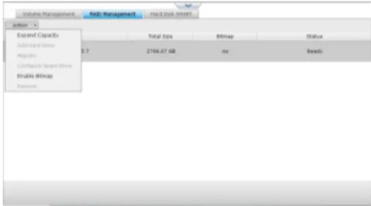
Note: Bitmap support is only available for RAID 1, 5, 6, and 10.
Recover (RAID Recovery)
RAID Recovery: When the NVR is congured as RAID 1, RAID 5, or RAID 6 and any number of hard drives is unplugged from the NVR accidentally, you can plug in the same hard drives into the same drive slots and click “Recover” to recover the volume status from “Not acve” to “Degraded mode”.
If the disk volume is congured as RAID 0 or JBOD and one or more of the hard drive members are disconnected or unplugged, you can plug in the same hard drives into the same drive slots and use this funcon to recover the volume status from "Not acve" to "Normal". The disk volume can be used normally aer successful recovery.
| Disk volume | Supports RAID recovery | Maximum number of disk removal allowed |
| Single | No | - |
| JBOD | Yes | 1 or more |
| RAID 0 | Yes | 1 or more |
| RAID 1 | Yes | 1 or 2 |
| RAID 5 | Yes | 2 or more |
| RAID 6 | Yes | 3 or more |
| RAID 10 | No | - |
Note:
Aer recovering a RAID 1, RAID 5 or RAID 6 disk volume from not acve to degraded mode by the RAID recovery, you can read or write the volume normally. The volume status will be recovered to normal aer synchronizaon. If the disconnected drive member is damaged, the RAID recovery funcon will not work.
| Standard RAID 5 | QNAP RAID 5 | Standard RAID 6 | QNAP RAID 6 | |
| Degraded mode | N-1 | N-1 | N-1 & N-2 | N-1 & N-2 |
| Read Only Protecon (for immediate data backup & hard drivereplacement) | N/A | N-1, bad blocks found in the surviving hard drives of the array. | N/A | N-2, bad blocks found in the surviving hard drives of the array. |
| RAID Recovery (RAID Status: Not Acve) | N/A | If re-plugging in all original hard drive to the NVR and they can be spun up, idened, accessed, and the hard drive superblock is not damaged. | N/A | If re- plugging in all original hard drives to the NVR and they can be spun up, idened, accessed, and the hard drive superblock is not damaged). |
| RAID Crash | N-2 | N-2 failed hard drives and any of the remaining hard drives cannot be spun up/idened/accessed. | N-3 | N-3 and any of the remaining hard drives cannot be spun up/idened/accessed. |
N = Number of hard disk drives in the array
Further informaon about RAID management of the NVR:
The NVR supports the following acons according to the number of hard disk drives and disk conguraons supported. Please refer to the following table for the details.
| Original Disk Conguraon * No. of Hard Disk Drives | No. of New Hard Disk Drives | Acon | New Disk Conguraon * No. of Hard Disk Drives |
| RAID 5 * 3 | 1 | Add hard drive member | RAID 5 * 4 |
| RAID 5 * 3 | 2 | Add hard drive member | RAID 5 * 5 |
| RAID 5 * 3 | 3 | Add hard drive member | RAID 5 * 6 |
| RAID 5 * 3 | 4 | Add hard drive member | RAID 5 * 7 |
| RAID 5 * 3 | 5 | Add hard drivemember | RAID 5 * 8 |
| RAID 5 * 4 | 1 | Add hard drive member | RAID 5 * 5 |
| RAID 5 * 4 | 2 | Add hard drive member | RAID 5 * 6 |
| RAID 5 * 4 | 3 | Add hard drive member | RAID 5 * 7 |
| RAID 5 * 4 | 4 | Add hard drive member | RAID 5 * 8 |
| RAID 5 * 5 | 1 | Add hard drive member | RAID 5 * 6 |
| RAID 5 * 5 | 2 | Add hard drive member | RAID 5 * 7 |
| RAID 5 * 5 | 3 | Add hard drive member | RAID 5 * 8 |
| RAID 5 * 6 | 1 | Add hard drive member | RAID 5 * 7 |
| RAID 5 * 6 | 2 | Add hard drive member | RAID 5 * 8 |
| RAID 5 * 7 | 1 | Add hard drive member | RAID 5 * 8 |
| RAID 6 * 4 | 1 | Add hard drive member | RAID 6 * 5 |
| RAID 6 * 4 | 2 | Add hard drive member | RAID 6 * 6 |
| RAID 6 * 4 | 3 | Add hard drive member | RAID 6 * 7 |
| RAID 6 * 4 | 4 | Add hard drive member | RAID 6 * 8 |
| RAID 6 * 5 | 1 | Add hard drive member | RAID 6 * 6 |
| RAID 6 * 5 | 2 | Add hard drive member | RAID 6 * 7 |
| RAID 6 * 5 | 3 | Add hard drive member | RAID 6 * 8 |
| RAID 6 * 6 | 1 | Add hard drive member | RAID 6 * 7 |
| RAID 6 * 6 | 2 | Add hard drive member | RAID 6 * 8 |
| RAID 6 * 7 | 1 | Add hard drive member | RAID 6 * 8 |
| RAID 10 * 4 | 2 | Add hard drive member | RAID 10 * 6 |
| RAID 10 * 4 | 4 | Add hard drive member | RAID 10 * 8 |
| RAID 10 * 6 | 2 | Add hard drive member | RAID 10 * 8 |
| RAID 1 * 2 | 1 | Online RAID capacity expansion | RAID 1 * 2 |
| RAID 5 * 3 | 1 | Online RAID capacity expansion | RAID 5 * 3 |
| RAID 5 * 4 | 1 | Online RAID capacity expansion | RAID 5 * 4 |
| RAID 5 * 5 | 1 | Online RAID capacity expansion | RAID 5 * 5 |
| RAID 5 * 6 | 1 | Online RAID capacity expansion | RAID 5 * 6 |
| RAID 5 * 7 | 1 | Online RAID capacity expansion | RAID 5 * 7 |
| RAID 5 * 8 | 1 | Online RAID capacity expansion | RAID 5 * 8 |
| RAID 6 * 4 | 1 | Online RAID capacityexpansion | RAID 6 * 4 |
| RAID 6 * 5 | 1 | Online RAID capacity expansion | RAID 6 * 5 |
| RAID 6 * 6 | 1 | Online RAID capacity expansion | RAID 6 * 6 |
| RAID 6 * 7 | 1 | Online RAID capacity expansion | RAID 6 * 7 |
| RAID 6 * 8 | 1 | Online RAID capacity expansion | RAID 6 * 8 |
| RAID 10 * 4 | 1 | Online RAID capacity expansion | RAID 10 * 4 |
| RAID 10 * 6 | 1 | Online RAID capacity expansion | RAID 10 * 6 |
| RAID 10 * 8 | 1 | Online RAID capacity expansion | RAID 10 * 8 |
| Single * 1 | 1 | Online RAID level migraon | RAID 1 * 2 |
| Single * 1 | 2 | Online RAID level migraon | RAID 5 * 3 |
| Single * 1 | 3 | Online RAID level migraon | RAID 5 * 4 |
| Single * 1 | 4 | Online RAID level migraon | RAID 5 * 5 |
| Single * 1 | 5 | Online RAID level migraon | RAID 5 * 6 |
| Single * 1 | 6 | Online RAID level migraon | RAID 5 * 7 |
| Single * 1 | 7 | Online RAID level migraon | RAID 5 * 8 |
| Single * 1 | 3 | Online RAID levelmigraon | RAID 6 * 4 |
| Single * 1 | 4 | Online RAID level migraon | RAID 6 * 5 |
| Single * 1 | 5 | Online RAID level migraon | RAID 6 * 6 |
| Single * 1 | 6 | Online RAID level migraon | RAID 6 * 7 |
| Single * 1 | 7 | Online RAID level migraon | RAID 6 * 8 |
| Single * 1 | 3 | Online RAID level migraon | RAID 10 * 4 |
| Single * 1 | 5 | Online RAID level migraon | RAID 10 * 6 |
| Single * 1 | 7 | Online RAID level migraon | RAID 10 * 8 |
| RAID 1 * 2 | 1 | Online RAID level migraon | RAID 5 * 3 |
| RAID 1 * 2 | 2 | Online RAID level migraon | RAID 5 * 4 |
| RAID 1 * 2 | 3 | Online RAID level migraon | RAID 5 * 5 |
| RAID 1 * 2 | 4 | Online RAID level migraon | RAID 5 * 6 |
| RAID 1 * 2 | 5 | Online RAID level migraon | RAID 5 * 7 |
| RAID 1 * 2 | 6 | Online RAID level migraon | RAID 5 * 8 |
| RAID 1 * 2 | 2 | Online RAID level migraon | RAID 6 * 4 |
| RAID 1 * 2 | 3 | Online RAID level migraon | RAID 6 * 5 |
| RAID 1 * 2 | 4 | Online RAID level migraon | RAID 6 * 6 |
| RAID 1 * 2 | 5 | Online RAID level migraon | RAID 6 * 7 |
| RAID 1 * 2 | 6 | Online RAID level migraon | RAID 6 * 8 |
| RAID 1 * 2 | 2 | Online RAID level migraon | RAID 10 * 4 |
| RAID 1 * 2 | 4 | Online RAID level migraon | RAID 10 * 6 |
| RAID 1 * 2 | 6 | Online RAID level migraon | RAID 10 * 8 |
| RAID 5 * 3 | 1 | Online RAID level migraon | RAID 6 * 4 |
| RAID 5 * 3 | 2 | Online RAID level migraon | RAID 6 * 5 |
| RAID 5 * 3 | 3 | Online RAID level migraon | RAID 6 * 6 |
| RAID 5 * 3 | 4 | Online RAID level migraon | RAID 6 * 7 |
| RAID 5 * 3 | 5 | Online RAID level migraon | RAID 6 * 8 |
Hard Disk S.M.A.R.T
Monitor the hard disk drives (HDD) health, temperature, and the usage status by HDD S.M.A.R.T. (Self-Monitoring Analysis and Reporng Technology).
The following informaon of each hard drive on the NVR is available.
| Field | Descripon |
| Summary | Display the hard drive S.M.A.R.T. summary and the latest test result. |
| Hard disk informaon | Display the hard drive details, for example, model, serial number, HDD capacity. |
| SMART informaon | Display the hard drive S.M.A.R.T. informaon. Any items that the values are lower than the threshold are regarded as abnormal. |
| Test | Perform quick or complete hard drive S.M.A.R.T. test. |
| Sengs | Congure temperature alarm. When the hard drive temperature is over the preset values, the NVR records the error logs.You can also set the quick and complete test schedule. The latest test result is shown on the Summary page. |
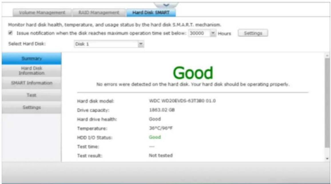
9.1.3 Network
TCP/IP
(i) IP Address
Congure the TCP/IP sengs, DNS Server and default Gateway of the NVR on this page.
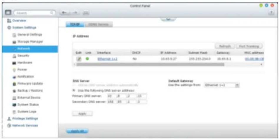
Click to edit the network sengs. For the NVR with two LAN ports, users can
connect both network interfaces to two dierent switches and conjure the TCP/IP sengs. The NVR will acquire two IP addresses which allow access from two dierent subnets. This is known as mul-IP sengs*. When using the Finder to detect the NVR IP, the IP of the Ethernet 1 will be shown in LAN 1 only and the IP of the Ethernet 2 will be shown in LAN 2 only. To use the port trunking mode for dual LAN conncon, see secon (iv).
Network Parameters
Under the Network Parameters tab on the TCP/IP Property page, congure the following sengs:
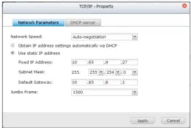
Network Speed
Select the network transfer rate according to the network environment to which the NVR is connected. Select auto negoaoon and the NVR will adjust the transfer rate automacally.
Obtain the IP address sengs automacally via DHCP
If the network supports DHCP, select this opon and the NVR will automacally obtain the IP address and network sengs.
Use stac IP address
To use a stac IP address for network conncon, enter the IP address, subnet mask, and default gateway.
Jumbo Frame Sengs (MTU)
“Jumbo Frames” refer to the Ethernet frames that are larger than 1500 bytes. It is designed to enhance Ethernet networking throughput and reduce the CPU ulizaon of large le transfers by enabling more ecient larger payloads per packet.
Maximum Transmission Unit (MTU) refers to the size (in bytes) of the largest packet that a given layer of a communicaons protocol can transmit.
The NVR uses standard Ethernet frames: 1500 bytes by default. If the network appliances support Jumbo Frame seng, select the appropriate MTU value for the network environment. The NVR supports 4074, 7418, and 9000 bytes for MTU.
Note: The Jumbo Frame seng is valid in Gigabit network environment only. All the network appliances connected must enable Jumbo Frame and use the same MTU value.
DHCP Server
A DHCP (Dynamic Host Conguraon Protocol) server assigns IP addresses to the clients on a network. Select "Enable DHCP Server" to set the NVR a DHCP server if there is none on the local network where the NVR locates.
Note:
Do not enable DHCP server if there is one the local network to avoid IP
- address conicts or network access errors.
The DHCP server opon is available to Ethernet 1 only when both LAN ports of a dual LAN NVR are connected to the network and Ethernet 1 is assigned
- with a xed IP.
Start IP, End IP, Lease Time: Set the range of IP addresses allocated by the NVR to the DHCP clients and the lease me. The lease me refers to the me that an IP address is leased to the clients. During that me, the IP will be reserved to the assigned client. When the lease me expires, the IP can be assigned to another client.
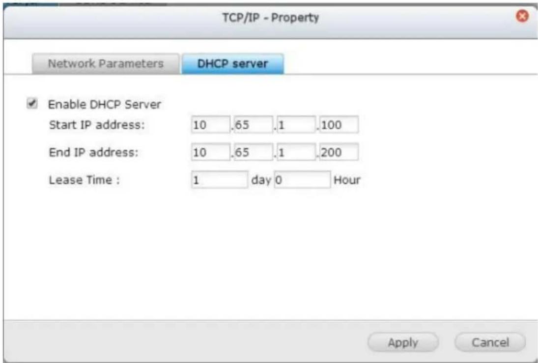
(ii) DNS Server
A DNS (Domain Name Service) server translates between a domain name (such as google.com) and an IP address (74.125.31.105). Congure the NVR to obtain a DNS server address automatically or specify the IP address of a DNS server.
Primary DNS Server: Enter the IP address of the primary DNS server. Secondary DNS Server: Enter the IP address of the secondary DNS server.
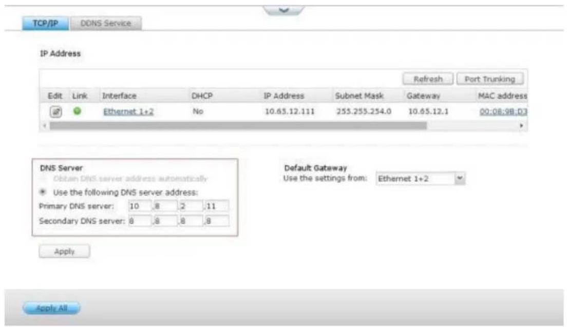
Note:
Please contact the ISP or network administrator for the IP address of the primary and the secondary DNS servers. When the NVR plays the role as a terminal and needs to perform independent conncon, for example, BT download, enter at least one DNS server IP for proper URL conncon.
- Otherwise, the funcon may not work properly.
If you select to obtain the IP address by DHCP, there is no need to congure - the primary and the secondary DNS servers. In this case, enter "0.0.0.0".
(iii) Default Gateway
Select the gateway sengs to use if both LAN ports have been connected to the network (dual LAN NVR models only).
(iv) Port Trunking
Applicable to NVR models with two or more LAN ports only.
The NVR supports port trunking which combines two Ethernet interfaces into one to increase the bandwidth and oers load balancing and fault tolerance (also known as failover). Load balancing is a feature which distributes the workload evenly across two Ethernet interfaces for higher redundancy. Failover is the capability to switch over to a standby network interface (also known as the slave interface) when the primary network interface (also known as the master interface) does not correspond correctly to maintain high availability.
To use port trunking on the NVR, make sure at least two LAN ports of the NVR have been connected to the same switch and the sengs described in seconds (i) and (ii) have been congured.
Follow the steps below to congure port trunking on the NVR:
1
. Click "Port Trunking".
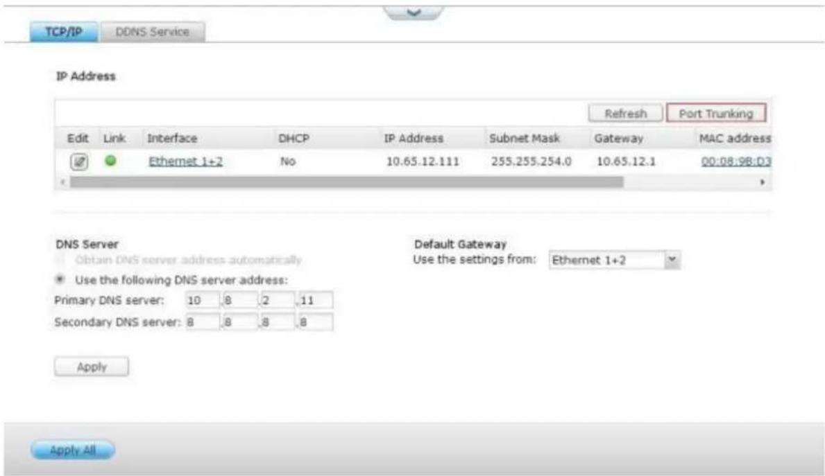
- Select the network interfaces for a trunking group (Ethernet 1+2, Ethernet 3+4, Ethernet 5+6, or Ethernet 7+8). Choose a port trunking mode from the drop-down menu. The default opon is Acve Backup (Failover).
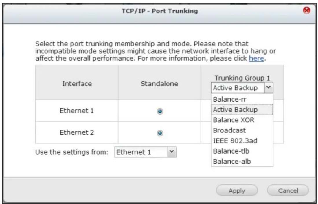
- Select a port trunking group to use. Click "Apply"
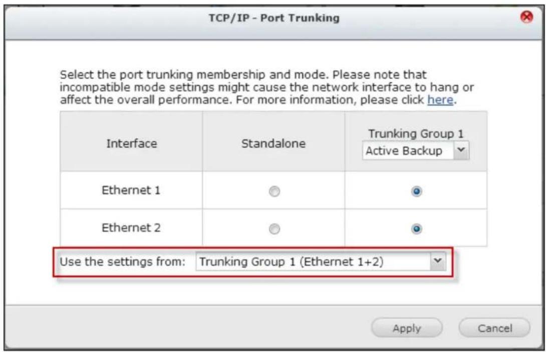
- Click "here" to connect to the login page.
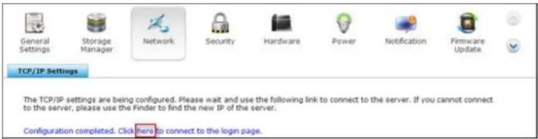
- Click the Edit buon under "IP Address" to edit the network sengs.
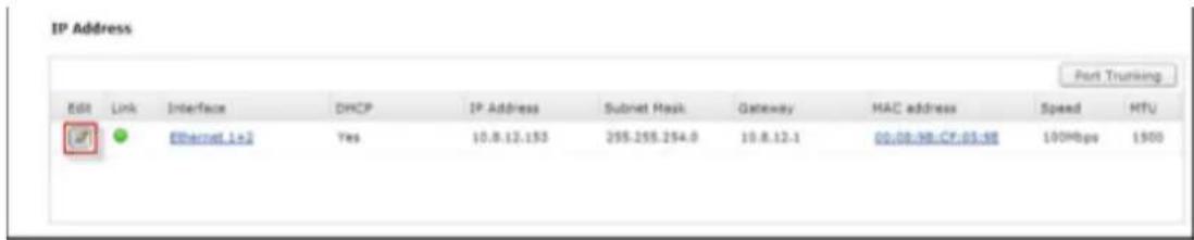
Note: Make sure the Ethernet interfaces are connected to the correct switch and the switch has been congured to support the port trunking mode selected on the NVR.
The port trunking opons available on the NVR:
| Field | Descripon | Switch Required |
| Balance-rr (Round-Robin) | Round-Robin mode is good for general purpose load balancing between two Ethernet interfaces. This mode transmits packets in sequenal order from the rst available slave through the last. Balance-rr provides load balancing and fault tolerance. | Supports stac trunking. Make sure stac trunking is enabled on the switch. |
| Acve Backup | Acve Backup uses only one Ethernet interface. It switches to the second Ethernet interface if the rst Ethernet interface does not work properly. Only one interface in the bond is acve. The bond's MAC address is only visible externally on one port (network adapter) to avoid confusing the switch. Acve Backup mode provides fault tolerance. | General switches |
| Balance XOR | Balance XOR balances trac by spling upoutgoing packets between the Ethernet interfaces, using the same one for each specic desnaon when possible. It transmits based on the selected transmit hash policy. The default policy is a simple slave count operang on Layer 2 where the source MAC address is coupled with desnaon MAC address. Alternate transmit policies may be selected via the xmit_hash_policy opon. Balance XOR mode provides load balancing and fault tolerance. | Supports stactrunking. Make sure stac trunking is enabled on the switch. |
| Broadcast | Broadcast sends trac on both network interfaces. This mode provides fault tolerance. | Supports stac trunking. Make sure stac trunking is enabled on the switch. |
| IEEE 802.3ad (Dynamic Link Aggregaon) | Dynamic Link Aggregaon uses a complex algorithm to aggregate adapters by speed and duplex sengs. It ulizes all slaves in the acve aggregator according to the 802.3ad specicaon. Dynamic Link Aggregaon mode provides load balancing and fault tolerance but requires a switch that supports IEEE 802.3ad with LACP mode properly congured. | Supports 802.3ad LACP |
| Balance-tlb (Adapve Transmit Load Balancing) | Balance-tlb uses channel bonding that does not require any special switch. The outgoing trac is distributed according to the current load on each Ethernet interface (computed relave to the speed). Incoming trac is received by the current Ethernet interface. If the receiving Ethernet interface fails, the other slave takes over the MAC address of the failed receiving slave. Balance-tlb mode provides load balancing and fault tolerance. | General switches |
| Balance-alb(Adapve Load Balancing) | Balance-alb is similar to balance-tlb but also aempts to redistribute incoming (receive load balancing) for IPV4 trac. This setup does not require any special switch support or conguraon. The receive load balancing is achieved by ARP negoaon sent by the local system on their way out and overwrites the source hardware address with the unique hardware address of one of the Ethernet interfaces in the bond such that dierent peers use dierent hardware address for the server. This mode provides load balancing and fault tolerance. | General switches |
DDNS Service
To allow remote access to the NVR using a domain name instead of a dynamic IP address, enable the DDNS service.
The NVR supports the DDNS providers: hp://www.dyndns.com,
hp://update.ods.org, http://www.dhs.org, hp://www.dyns.cx,
hp://www.3322.org, hp://www.no-ip.com.
9.1.4 Security
Security Level
Specify the IP address or the network domain from which the connecons to the NVR are allowed or denied. When the connecon of a host server is denied, all the protocols of that server are not allowed to connect to the NVR.
Aer changing the sengs, click “Apply” to save the changes. The network services will be restarted and current connecons to the NVR will be terminated.
Certificate & Private Key
The Secure Socket Layer (SSL) is a protocol for encrypted communicaon between the web servers and the web browsers for secure data transfer. You can upload a secure cercate issued by a trusted provider. Aer uploading a secure cercate, users can connect to the administraon interface of the NVR by SSL conncon and there will not be any alert or error message. The NVR supports X.509 cercate and private key only.
Download Cercate: To download the secure cercate which is currently in use.
Download Private Key: To download the private key which is currently in use.
private key to system default. The secure cercate and private key in use will be
overwrien.
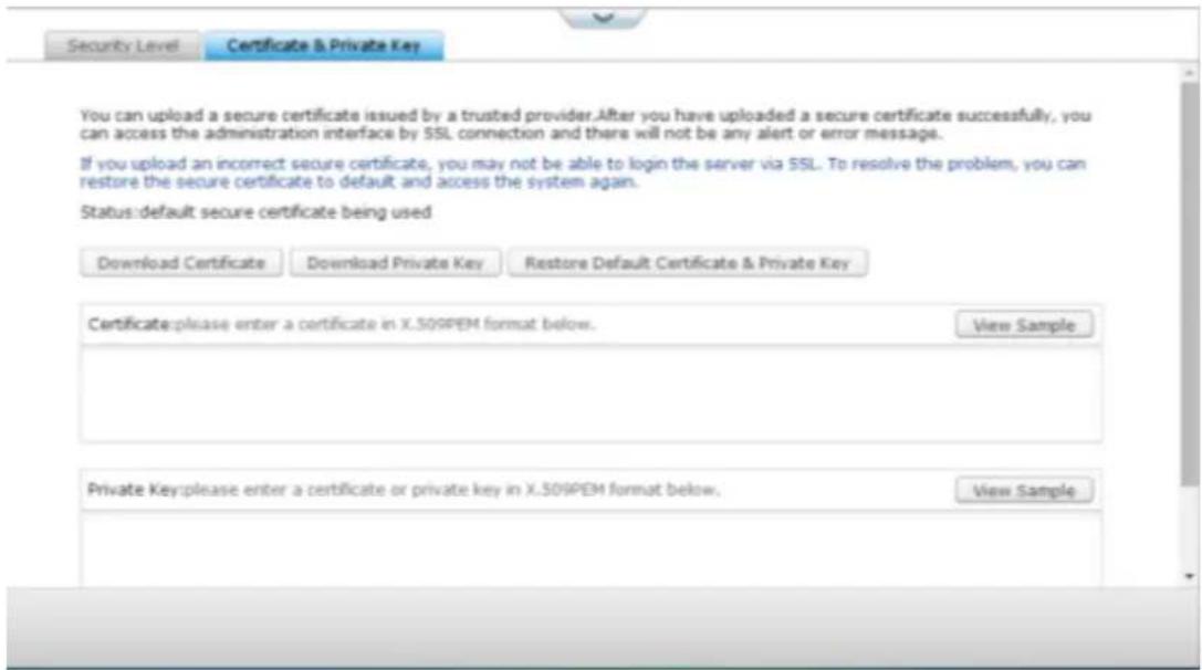
9.1.5 Hardware
Congure the hardware funcons of the NVR.
General
Enable conguraon reset switch
When this funcon is turned on, you can press the reset buon for 3 seconds to reset the administrator password and the system sengs to default. The disk data will be retained.
System
Basic system reset
Advanced system reset
(1 beep)
(2 beeps)
All NVR models
Press the reset buon for 3 sec
Press the reset buon for 10 sec
Basic system reset (3 sec)
Aer pressing the reset buon for 3 seconds, a beep sound will be heard. The following sengs will be reset to default:
System administraon password: admin.
TCP/IP conguraon: Obtain IP address setngs automacally via DHCP.
TCP/IP conguraon: Disable Jumbo Frame.
TCP/IP conguraon: If port trunking is enabled (dual LAN models only), the port trunking mode will be reset to “Active Backup (Failover)”.
System port: 80 (system service port).
Security level: Low (Allow all connecons).
LCD panel password: (blank)*.
*This feature is only provided by the NVR models with LCD panels.
Advanced system reset (10 sec)
Aer pressing the reset buon for 10 seconds, you will hear two beeps at the third and the tenth seconds. The NVR will reset all the system sengs to default as it does by the web-based system reset in “Administration” > “Restore to Factory Default” except all the data are reserved. The sengs such as the users, user groups, and the shared folders previously created will be cleared.
Enable light signal alert when the free size of SATA disk is less than the value: The status LED ashes red and green when this opon is turned on and the free space of the SATA hard drive is less than the value. The valid range of the value is 1-51200 MB.
Enable warning alert for redundant power supply on the web-based interface: If two power supply units (PSU) are installed on the NVR and connected to the power sockets, both PSU will supply the power to the NVR (applied to 1U and 2U models). Turn on the redundant power supply mode in “System Settings” > “Hardware” to receive warning alert for the redundant power supply. The NVR will sound and record the error messages in “System Logs” when the PSU is plugged out or does not correspond correctly.
If only one PSU is installed on the NVR, do NOT enable this opon.
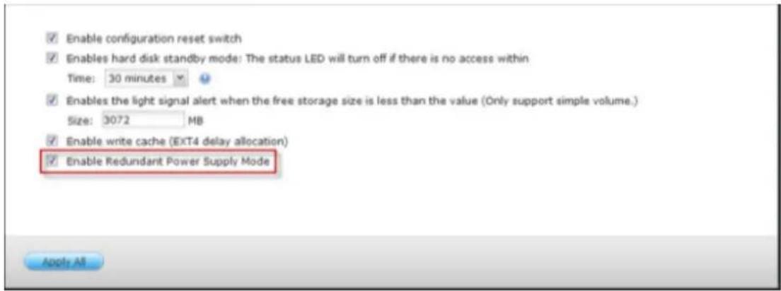
* This funcon is disabled by default.
Buzzer
Enable alarm buzzer
Turn on this opon to allow the alarm buzzer to beep when certain system operaons (startup, shutdown, or rmware upgrade) are executed or system events (error or warning) occur.
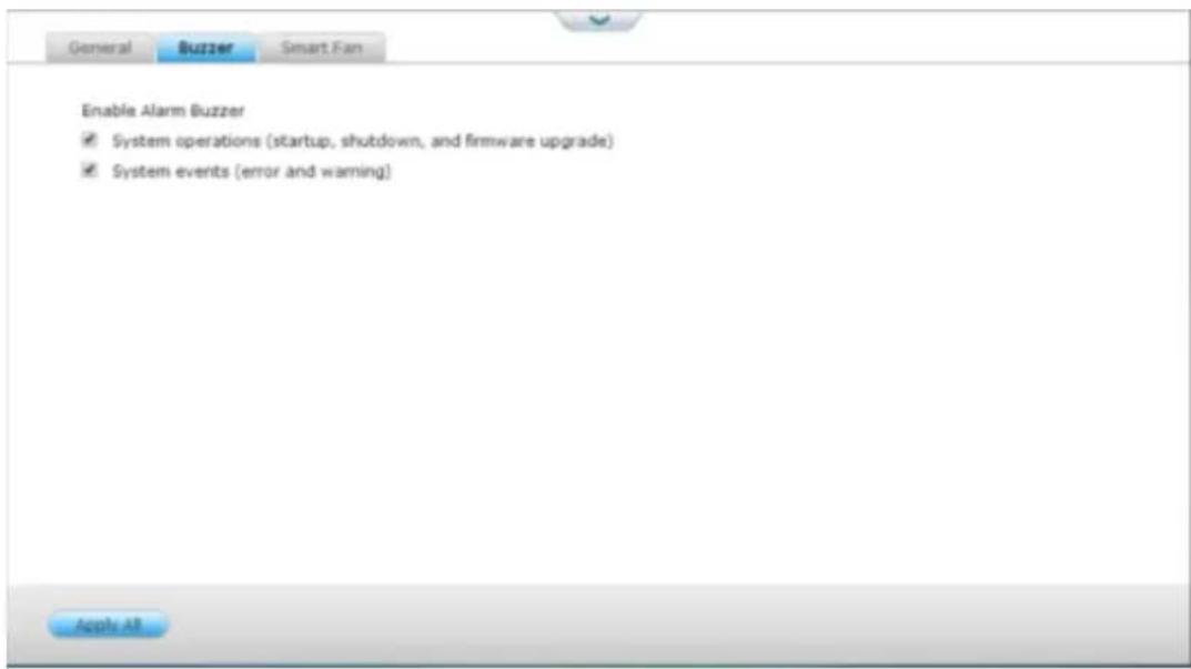
Smart Fan Conguraon:
Enable smart fan (recommended)
Select to use the default smart fan sengs or dene the sengs manually. When the system default sengs are selected, the fan rotaon speed will be
automacally adjusted when the NVR temperature, CPU temperature, and hard
drive temperature meet the criteria. It is recommended to enable this opon.
Set fan rotaon speed manually
By manually seng the fan rotaon speed, the fan rotates at the dened speed connuously.
9.1.6 Power
Power Recovery
Congure the NVR to resume to the previous power-on or power-o status, turn on, or remain o when the AC power resumes aer a power outage.
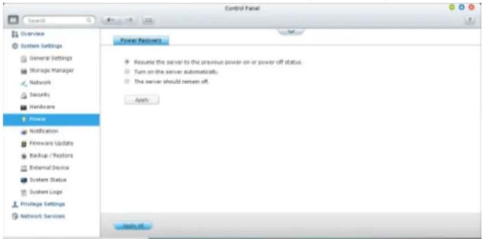
9.1.7 Notification
E-mail
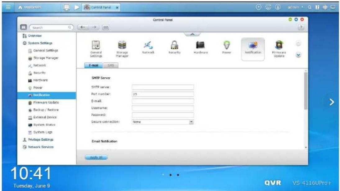
SMTP Server
The NVR supports email alerts to inform the administrator of system errors and warning. To receive alerts by email, congure the SMTP server.
- SMTP server: Enter the SMTP server name, for example, smtp.gmail.com.
- Port number: Enter the port number for the SMTP server. The default port number is 25.
• E-mail: Enter the email address of the alert recipient.
• User name and Password: Enter the login information of the email account. - Secure conncon: Choose SSL or TLS to ensure a secure conncon between the NVR and SMTP server, or None based on your needs. It is recommended to enable this funcon if the SMTP server supports it.
Email Notification
You can toggle email nocaons for all error events or warning events.
A maximum of ve email addresses are allowed.
The sengs here will be synced with [Surveillance Sengs] -> [Camera Sengs] -> [Event Management] -> E-mail sengs when choosing Tradional Mode.
SMS
SMSC Settings
Congure the SMSC server sengs to send SMS messages to specied phone numbers from the NVR. The default SMS service provider is Clickatell. You can add your own SMS service provider by selecng "Add SMS Provider" from the drop-down menu.
When “Add SMS service provider” is selected, enter the name of the SMS provider and the URL template text.
SMS Notification
You can toggle SMS messages for all error events or warning events.
A maximum of two phone numbers are allowed.
The sengs here will be synced with [Surveillance Sengs] -> [Camera Sengs] -> [Event Management] -> SMS sengs when choosing Tradional Mode..
9.1.8 Firmware Update
Live Update
Select “Automacally check if a newer version is available when logging into the NVR web administraon interface” to allow the NVR to automacally check if a new rmware version is available for download from the Internet. If a new rmware is found, you will be noed aer logging in the NVR as an administrator.
Click "Check for Update" to check if a rmware update is available.
Note that the NVR must be connected to the Internet for these features to work.
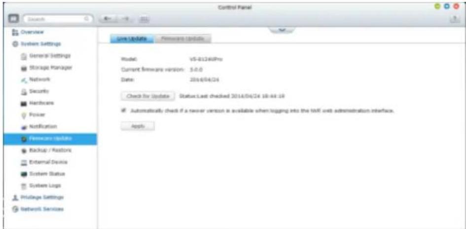
Firmware Update
![Model: V5-0124Pro Current firmware version: 3.6.0 Date: 2014/04/24 Before updating system firmware, please make sure the product model and firmware version are correct. Follow the steps below to update firmware: 1. Download the release notes of the same version as the firmware has QGAP website http://www.qgapwarts.com; void the release notes carefully to make sure you need to update the firmware. 2. Before updating system firmware, back up all disk data on the server to avoid any potential data loss during system update; 3. Click the [Browse...] button to select the current firmware image for ordinary updates. Click the [Update System] button to update the firmware. Browse... update button System updates may take here of records or several minutes to complete depending on the network tomorrow's status, please exit patients. The system will inform you when current update is completed.](/content/2026/05/1128063/images/018729a2d2ad3a45d2dd6411e3bc6e88843218f282fdd4e32a50b691e2a320b4.jpg)
Note: If the system is running properly, you do not need to update the rmware.
Before updang the system rmware, make sure the product model and rmware version are correct. Follow the steps below to update rmware:
Download the release notes of the rmware from the QNAP Security website hp://www.qnapsecurity.com. Read the release notes carefully to make sure it is
- required to update the rmware.
- Download the NVR rmware and unzip the IMG le to the computer.
Before updang the system rmware, back up all the disk data on the NVR to - avoid any potential data loss during the system update.
Click "Browse" to select the correct rmware image for the system update. Click - "Update System" to update the rmware.
The system update may take tens of seconds to several minutes to complete depending on the network conncon status. Please wait paently. The NVR will inform you when the system update has completed.
Update Firmware by QNAP Qnder
The NVR rmware can be updated by the QNAP Qnder. Follow the steps below:
- Select a NVR model and choose "Update Firmware" from the "Tools" menu.
![QNAP (Windows 8.1.2) Server Control Settings [Tools] Help Map Network Drive Reset Sensor Shut driver Server Remote Wake Up (Wake On LAN) Search Network Camera WAPP Settings Update Hardware Resource Manager Photo updated Network Provider Other QNet Service Player Service Manager VSM 2000 VS 01-46Pto+ VS-41(6)Pto+ VS-21(2)Pto+ VS-20(2)Pto TVS-470 TS-ECB79U-RP TS-ECB79U-RP TS-EC1679U-SAS-RP TS-879 Pro TS-879 Pro TS-870 Pro TS-870 Pro TS-8690-RP TS-669 Pro TS-659 Pro E VSM 2000 1.1.15 (20140313) 4.2.0 (7426) 5.0.0 (20140419) 4.2.0 (7531) 5.0.0 (20140419) 4.1.0 (20140421) 3.7.3 (20120801) 3.7.3 (20120801) 4.1.0 (20140423) 4.6.5 (20131023) 4.1.0 (20131220) 4.0.7 (20140410) 4.1.0 (20131219) 3.7.3 (20120801) 4.1.0 (20140411) 4.0.5 (20140117) 4.6.8 (20140417)](/content/2026/05/1128063/images/0e6376fcafebc5cd2b1713c0abe447f4a95d8e9abd91beb41d937d47ecc0edb3.jpg)
- Login the NVR as an administrator.
- Browse and select the rmware for the NVR. Click "Start" to update the system.
Note: The NVR servers of the same model on the same LAN can be updated by the Finder at the same me. Administrator access is required for system update.
Back up System Sengs
To back up all the sengs, including the user accounts, server name, network conguraon and so on, click "Backup" and select to open or save the seng le.
Restore System Sengs
To restore all the sengs, click "Browse" to select a previously saved seng le and click "Restore".
Restore to Factory Default
To reset all the system sengs to default, click "RESET" and then click "OK".

Cauon: When "RESET" is pressed on this page, all the disk data, user accounts, shared folders, and system sengs will be cleared and restored to default. Always back up all the important data and system sengs before reseng the NVR.
To reset the NVR by the reset button, see "System Setngs" > "Hardware".
![Backup/Restore Settings Restore to Factory Default To reset all settings to default, click [Reset]. Caution: When you press [Reset] on this page, all drive data, user accounts, network shares and system settings are cleared and restored to default. Please make sure you have backed up all the important data and system settings before resetting the NVR. Reset:](/content/2026/05/1128063/images/469e8bf66888887986ba90d6ed40328eba5ade7dd88d8151e34dab63aadd4446.jpg)
9.1.10 External Device
External Storage
The NVR supports external USB storage devices* for backup and data storage.
Connect the external storage device to a USB interface of the NVR, when the device is successfully detected, the details will be shown on this page.
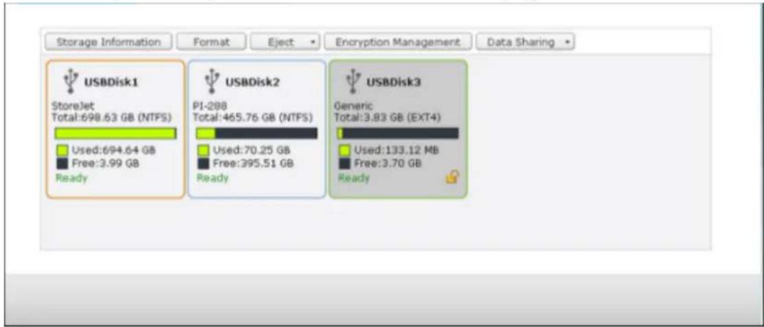
Storage Informaon
Select a storage device and click Storage Informaon to check for its details.
| Storage Information | |
| Storage Name | USBDisk2 |
| Manufacturer | PI-288 |
| Model | USB 2.0 Drive |
| Total / Free Size | 465.76 GB / 395.51 GB |
| File System | NTFS |
| Shared Folder | USBDisk2 |
| Device Type | USB 2.0 |
| Status | Ready |
*The number of USB interfaces supported varies by models. Please refer to hp://www.qnapsecurity.com for details.
It may take tens of seconds for the NVR server to detect the external USB device successfully. Please wait paently.
Format
The external storage device can be formed as EXT3, EXT4, FAT32, NTFS, or HFS+ (Mac only) le system. Click "Format" and select the option from the drop-down menu.
The NVR supports external drive encrypon. To encrypt an external storage device, click “Encrypon”. Select the encrypon method: AES 128-, 192- or 256-bit and enter the password (8-16 characters). Select “Save encrypon key” to save the password in a hidden locaon on a hard drive of the NVR. The NVR will unlock the encrypted external storage device automacally every me the device is connected. Click Format to proceed.
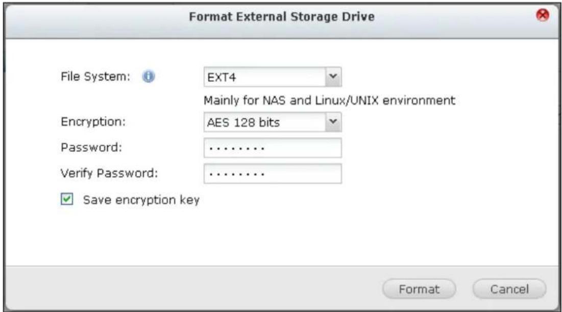
Click "OK" and all the data will be cleared.

The device will be "Ready" aer disk inializaon.
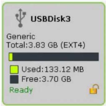
Eject
"Eject" oers two dierent opons. "Disconnect disk paron" allows you to remove a single disk paron or a disk drive in a mul-drive enclosure. "Remove external device" allows you to disconnect external storage devices without the risk of losing any data when the device is removed.
First choose a device to eject, click "Eject" and then to disconnect the disk paron or remove the device.
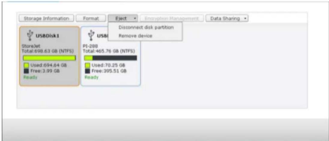
Encrypon management
If an external storage device is encrypted by the NVR, the buon “Encrypon Management” will appear. Click this buon to manage the encrypon password/key, or lock or unlock the device.
Lock the device
Note: The external storage device cannot be locked if a real-me or scheduled backup job is running on the device. To disable the backup job, go to "Control Panel" > "External Device" > "External Storage"
- To lock an encrypted external storage device, click "Encrypon Management".
- Select "Lock this device" and click "Next".
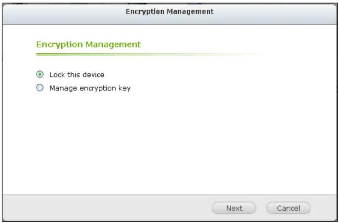
- Click "Next" to lock the device.
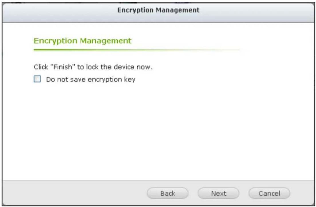
Unlock the device
- To unlock an encrypted external storage device, click "Encrypon Management".
- Select "Unlock this device". Click "Next"
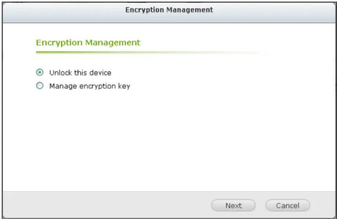
Enter the encrypon password or upload the key le. Select "Save encrypon key" to save the password in a hidden locaon on a hard drive of the NVR. The NVR will unlock the encrypted external storage device automatically every me
- the device is connected. Click "Next".
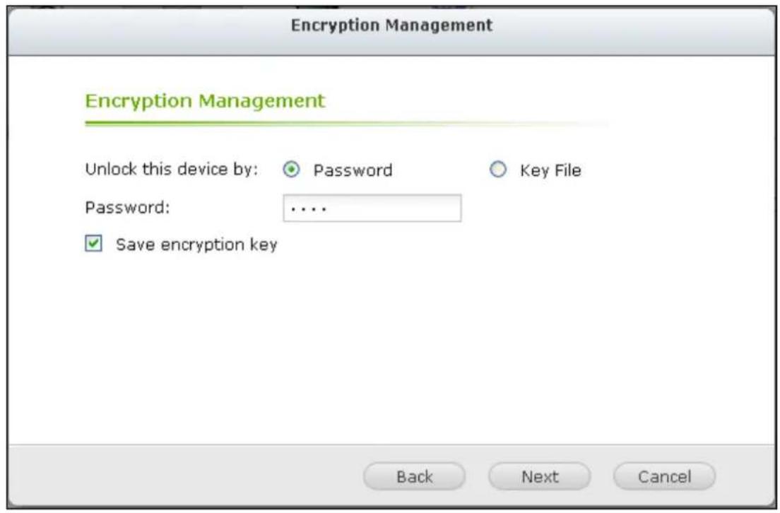
Manage the encrypon key
To change an encrypon password or download an encrypon key le, click
- "Encrypon Management".
- Select "Manage encrypon key". Click "Next".
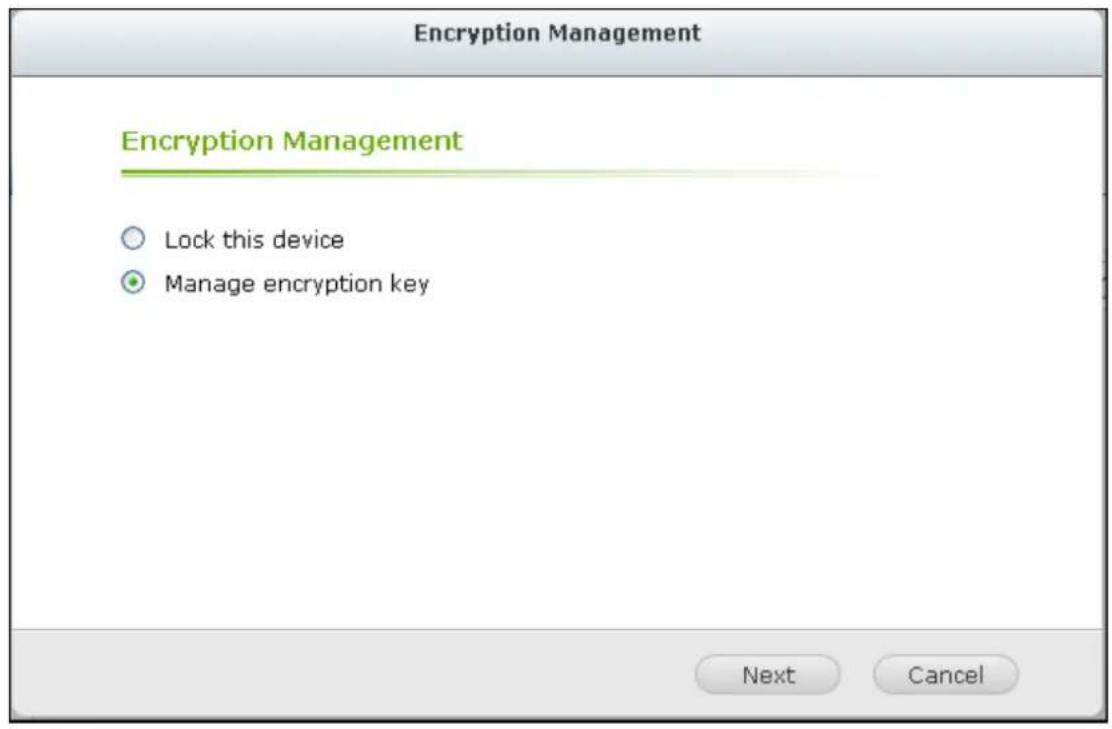
Select to change the encrypon password or download the encrypon key le to 3. the local PC. Click "Next".
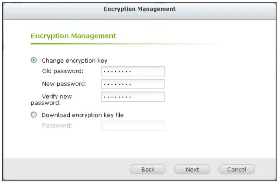
UPS
By enabling the UPS (Uninterruptible Power Supply) support, you can protect your NVR from abnormal system shutdown caused by power disrupon. In the event of a power failure the NVR will shut down automacally or enter auto-protecon mode by probing the power status of the connected UPS unit.
Standalone mode - USB
To operate under USB standalone mode, follow the steps below:
- Plug in the USB cable on the UPS to the NVR.
- Select the opon "Enable UPS Support".
Choose between whether the NVR will shut down or enter auto-protecon mode aer AC power fails. Specify the me in minutes that the NVR should wait before execung the opon you have selected. Aer the NVR enters auto-protecon
- mode, the NVR resumes the previous operaon status when the power restores.
- Click "Apply All" to conrm.
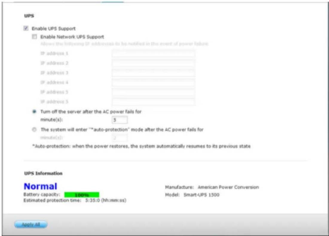
Standalone mode – SNMP
To operate under SNMP standalone mode, follow the steps below:
- Make sure the NVR is connected to the same physical network as the
SNMP-based UPS.
- Select the opon "Enable UPS Support".
- Select "APC UPS with SNMP management" from the "Protocol" drop down menu.
- Enter the IP address of the SNMP-based UPS.
Choose between whether the NVR will shut down or enter auto-protecon mode aer AC power fails. Specify the me in minutes that the NVR should wait before execung the opon you have selected. Aer the NVR enters auto-protecon - mode, the NVR resumes the previous operaon status when the power restores.
- Click "Apply All" to conrm.
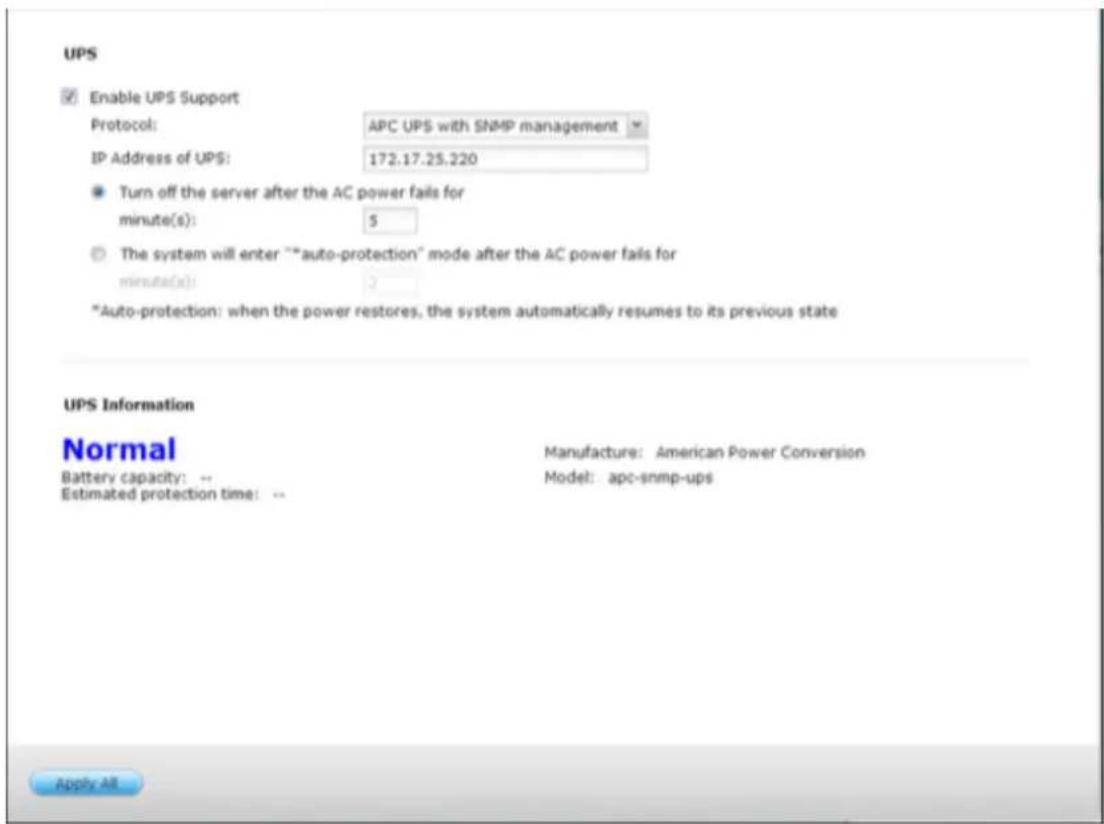
Network master mode
A network UPS master is responsible for communicating with network UPS slaves on the same physical network about critical power status. To set up your NVR with UPS as network master mode, plug in the USB cable on the UPS to the NVR and follow the steps below:
Make sure the NVR (the "UPS master") is connected to the same physical
- network as the network UPS slaves.
- Select the opon "Enable UPS Support".
- Click "Enable network UPS Support". This opon appears only when your NVR is
connected to the UPS by a USB cable.
Choose between whether the NVR will shut down or enter auto-protecon mode aer AC power fails. Specify the me in minutes that the NVR should wait before execung the opon you have selected. Aer the NVR enters auto-protecon
-
mode, the NVR resumes the previous operaon status when the power restores.
-
Enter the "IP address" of other network UPS slaves to be noed in the event of power failure.
-
Click "Apply All" to conrm and connue the setup for the NVR systems which operate in network slave mode below.
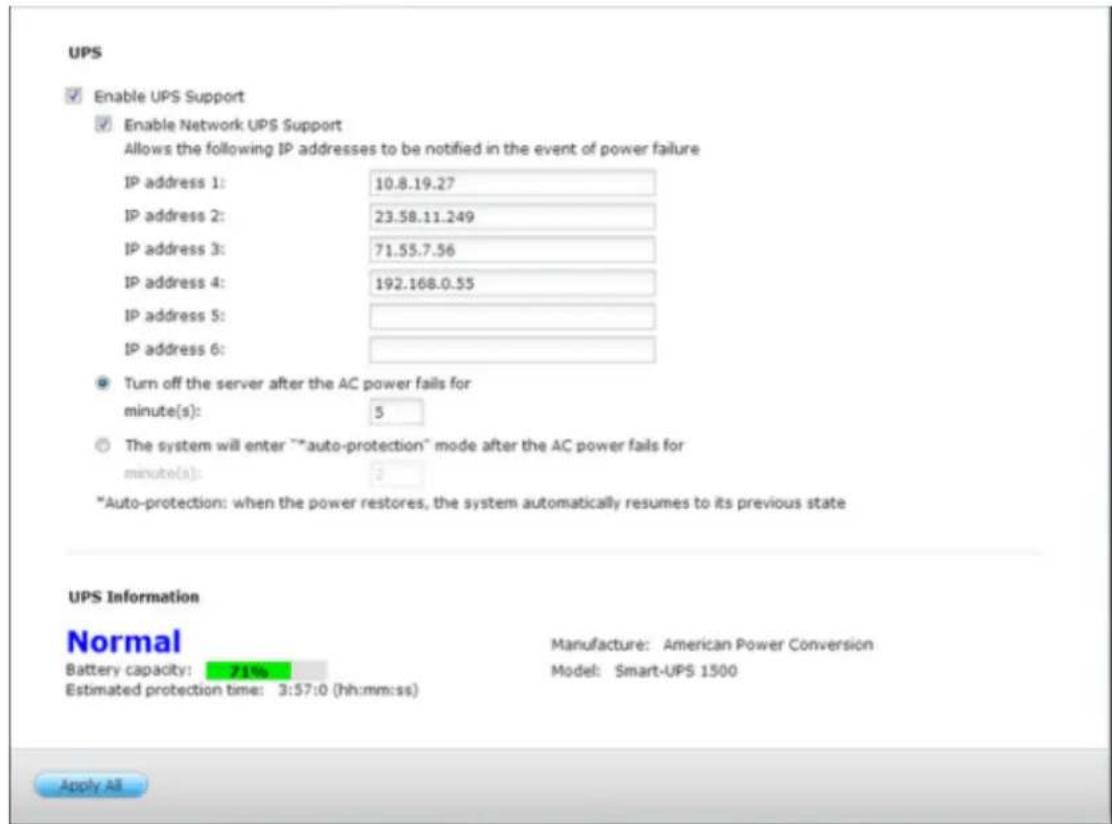
Network slave mode
A network UPS slave communicates with network UPS master to receive the UPS status. To set up your NVR with UPS as network slave mode, follow the steps below:
- Make sure the NVR is connected to the same physical network as the network UPS master.
- Select the opon "Enable UPS Support".
- Select "Network UPS slave" from the "Protocol" drop down menu.
- Enter the IP address of the network UPS server.
- Choose between whether the NVR will shut down or enter auto-protecon
mode aer AC power fails. Specify the me in minutes that the NVR should wait before execung the opon you have selected. Aer the NVR enters auto-protecon mode, the NVR resumes the previous operaon status when the power restores.
- Click "Apply All" to conrm.
Note: To allow the UPS device to send SNMP alerts to the QNAP NVR in case of power loss, you may have to enter the IP address of the NVR in the conguraon page of the UPS device.
Behavior of the UPS feature of the NVR
In case of power loss and power recovery, the events will be logged in the “System Event Logs”.
During a power loss, the NVR will wait for the specied me you enter in the "UPS Sengs" before powering o or entering auto-protecon mode.
If the power restores before the end of the waing me, the NVR will remain in operaon and cancel its power-o or auto-protecon acon.
Once the power restores:
If the NVR is in auto-protecon mode, it will resume to normal operaon.
If the NVR is powered o, it will remain o.
Difference between auto-protection mode and power-off mode
| Mode | Advantage | Disadvantage |
| Auto-protecon mode | The NVR resumes aer power recovery. | If the power outage lasts unl the UPS is turned o, the NVR may suer from abnormal shutdown. |
| Power-o mode | The NVR will be shut down properly. | The NVR will remain o aer the power recovery. Manual power on of the NVR is required. |
If the power restores aer the NVR has been shut down and before the UPS device is powered o, you may power on the NVR by Wake on LAN* (if your NVR and UPS device both support Wake on LAN and Wake on LAN is enabled on the NVR).
If the power restores aer both the NVR and the UPS have been shut down, the NVR will react according to the settings in “System Settings” > “Power Recovery”.
9.1.11 System Status
System Information
View the summary of system informaon such as the server name, memory, rmware and system up me on this page.
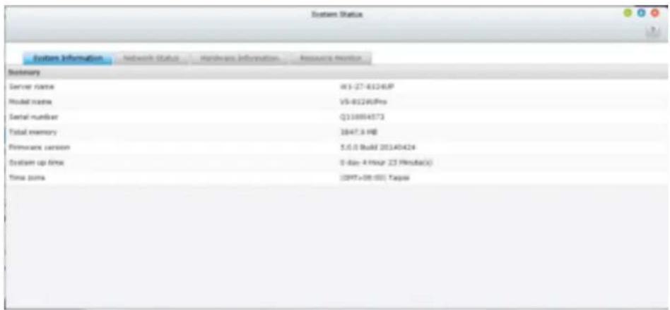
Network Status
View the current network sengs and stascs on this page and they are displayed based on network interfaces. Click the up arrow at top right to collapse the interface page and down arrow to expand the page.
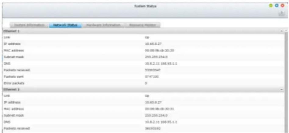
Hardware Information
View basic hardware informaon of the NVR on this page.
Resource Monitor
You can view the CPU usage, disk usage, and bandwidth transfer stascs of the NVR on this page.
CPU Usage: This tab shows the CPU usage of the NVR.
Memory Usage: This tab shows the memory usage of the NVR by real-me dynamic graph.
- Disk Usage: This tab shows the disk space usage of each disk volume and its shared folders.
- Bandwidth Usage: This tab provides informaon about bandwidth transfer of each available LAN port of the NVR.
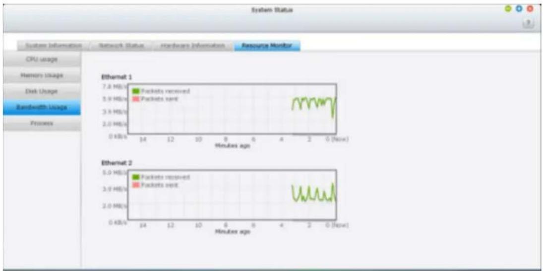
line
| Metric | Minutes ago | | ---------------- | ----------- | | Packets received | 7.8 MB/s | | Packets sent | 5.9 MB/s | | Packets sent | 3.9 MB/s | | Packets sent | 2.0 MB/s | | Packets received | 0.0 KB/s | | Packets sent | 0.0 KB/s |Process: This tab shows informaon about the processes running on the NVR.
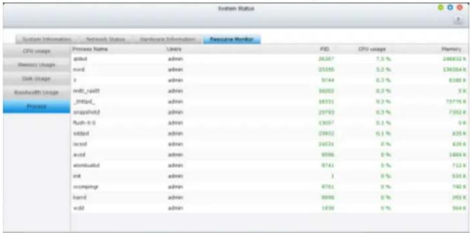
9.1.12 System Logs
Recording Statistics
The NVR can store 10,000 recent event logs, including warning, error, and informaon messages. If the NVR does not funcon correctly, refer to the event logs for troublesomeong.
![Recording Statistics System Connection Logs Online Users All events Save Type Date Time Users Source IP Computer name Content 2014-02-05 10:47:29 System 127.0.0.1 localhost CMS-Lite 0.52 has been installed in /share/HDA_DATA/.qpkg/CMS-Lite. 2014-02-05 10:47:08 System 127.0.0.1 localhost VCAM 0.1 has been installed in /share/HDA_DATA/.qpkg/VCAM. 2014-02-05 09:25:35 System 127.0.0.1 localhost System started. 2014-02-05 09:23:12 System 127.0.0.1 localhost System was shut down on Wed Feb 5 09:23:12 CST 2014. 2014-02-05 09:21:44 admin 10.8.10.96 --- [Power Management] System will be restart now. 2014-02-05 09:20:39 System 127.0.0.1 localhost [Firmware Upgrade] System updated successfully from 5.0.0(20140117 to 5.0.0(20140205). 2014-02-05 09:18:11 System 127.0.0.1 localhost [Firmware Upgrade] Start to update the firmware. 2014-01-29 11:48:48 System 127.0.0.1 localhost mvQNAPcloud user [mikeshaw@qnap.com] has been signed in 2014-01-29 11:48:42 System 127.0.0.1 localhost mvQNAPcloud CloudLink has been turned on 2014-01-29 11:48:37 System 127.0.0.1 localhost mvQNAPcloud DDNS has been turned on 2014-01-28 13:34:54 System 127.0.0.1 localhost System started. 2014-01-28 13:32:34 System 127.0.0.1 localhost System was shut down on Tue Jan 28 13:32:34 CST 2014. 2014-01-28 13:31:53 admin 10.8.10.324 [Device Management] System will be restart now Page 1 /2 H Display item: 1-50, Total: 52 Show 50 Items](/content/2026/05/1128063/images/3945341d3b17a847766f8ddb677c0546f160106e74926e5e169992d0dfc0eb3d.jpg)
System Connection Logs
The NVR supports recording HTTP, FTP, Telnet, SSH, AFP, SAMBA, and iSCSI connnecons. Click “Opons” to select the conncon type to be logged. The le transfer performance can be slightly aected when this feature is turned on.
Tip: Right click a log and select to delete the record or block the IP and select how long the IP should be blocked. To clear all the logs, click "Clear".
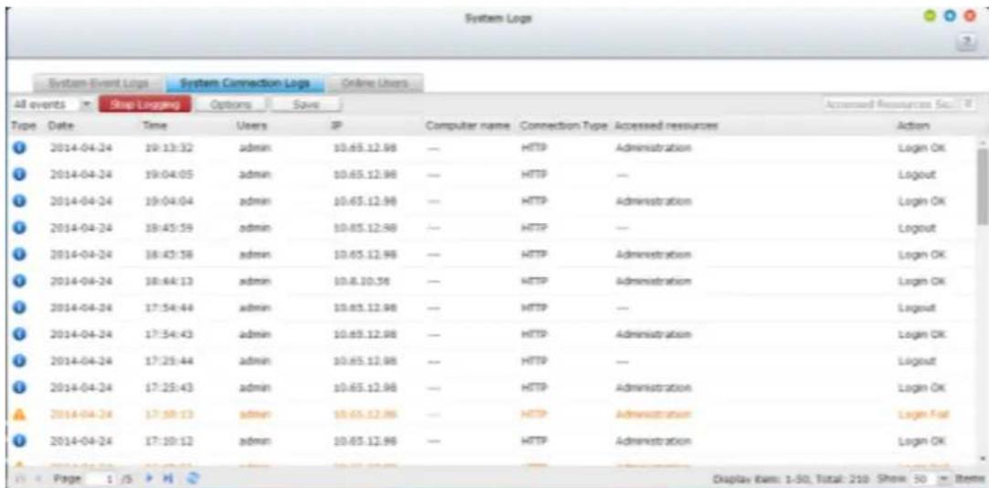
Start Logging: Turn on this opon to archive the conneccon logs. The NVR generates a CSV le automacally and saves it to a specied folder when the number of logs reaches the upper limit.
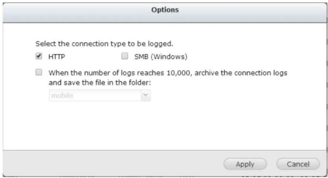
The le-level access logs are available on this page. The NVR will record the logs when users access, create, delete, move, or rename any les or folders via the conncon type specied in "Opons".
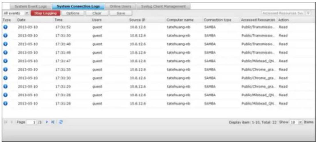
Online Users
The informaon of the on-line users connecng to the NVR by networking services is shown on this page.
Tip: You can disconnect the IP conncon, add it to the blocked IP list and select how long you want it to be blocked.
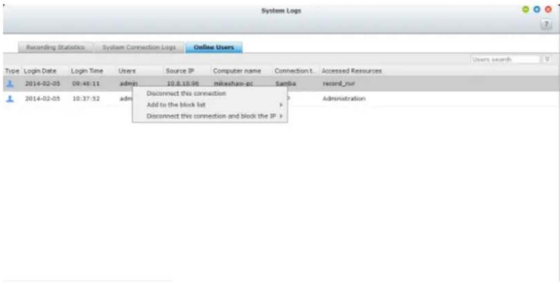
Advanced Log Search
Advanced log search is provided to search for system event logs, system conncon logs and online users based on user preferences. First, specify the log type, users, computer name, date range and source IP and click “Search” to search for the desired logs or reset to list all logs.
![System Logs System Event Logs System Connection Logs Online Users Edaylog Client Management All events Clear Save Log type: All events Data: 2013-05-03 2013-05-11 Users: systemITO: Computer name: Date Time Users三人源IP Customer name Centnt. 2013-05-07 17:07:04 System 127.0.0.1NBC localhost [Drive 1] The scanning is stopped by user. 2013-05-07 17:06:55 System 127.0.0.1NBC localhost [Drive 1] Start scanning bad blocks. 2013-05-06 08:04:00 System 127.0.0.1NBC localhost [USBOisk2] Device detected. The file system is ntfs. 2013-05-06 02:46:29 System 127.0.0.1NBC localhost [USBOisk2] Device removed. 2013-05-03 23:23:50 System 127.0.0.1NBC localhost [video Station] Video Station is enabled successfully. Search Reset Display item: 1-5, Total: 5 | Show 50 Items](/content/2026/05/1128063/images/6d4cbe6bf69ce1cb627569477e53276071744b0beb181068d4b6602a9ee0f521.jpg)
Please note that for online users, only the source IP and Computer name can be specied.
9.2 Privilege Settings
The NVR supports 3 types of users:
1. administrator
The system default administrator accounts are ‘admin’ and ‘supervisor’ (default password: admin). Both of them have the rights of system administraon, monitoring, and playback. The administrators cannot be deleted. They have the rights to create and delete new administrators, system managers, and general users, and change their passwords. Other newly created ‘administrators’ have the rights of system administraon, monitoring, and playback but some rights are dierent from ‘admin’ and ‘supervisor’.
2. system manager
The default system manager account is 'sysmgr' (default password: admin). This account has the right of system administraon and cannot be deleted. 'sysmgr' can create and delete other system manager and general user accounts, and assign monitoring, playback, and administraon rights to them. Other newly created system managers will also have the administraon right but some rights are dierent from 'sysmgr'.
3. user
The general users have only the rights of monitoring and video playback. They have no administraon authority.
The following information is required to create a new user:
Username: The username is case-insensitive and supports mul-byte characters, such as Chinese, Japanese, Korean, and Russian. The maximum length is 32
characters. The invalid characters are: "/ \ [ ] : ; | = , + * ? < > `'
- Password: The password is case-sensitive and supports maximum 16 characters. It is recommended to use a password of at least 6 characters.
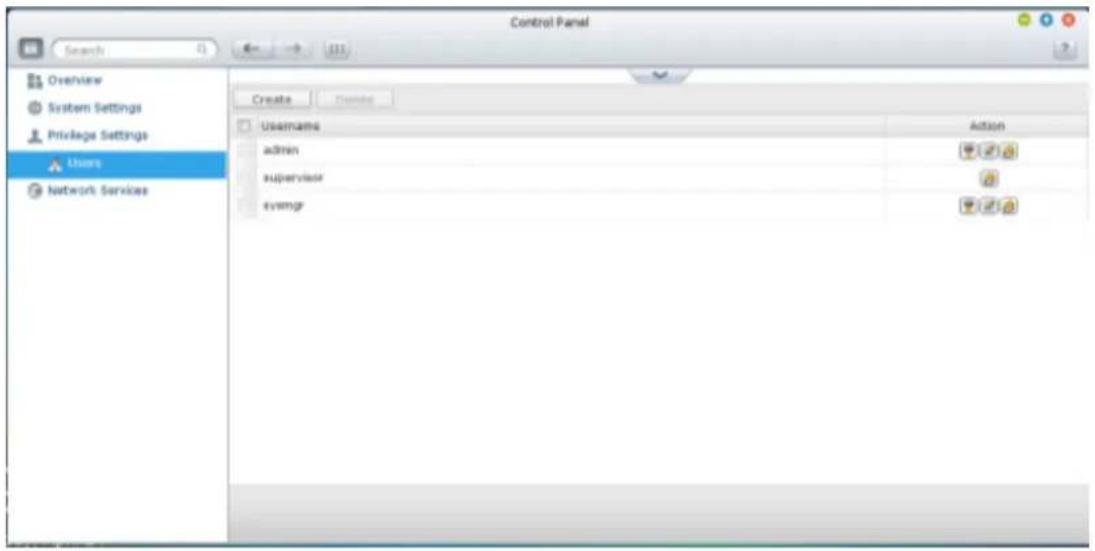
Create a User
To create a user on the NVR, click "Create".
Follow the instructions of the wizard to complete the details.
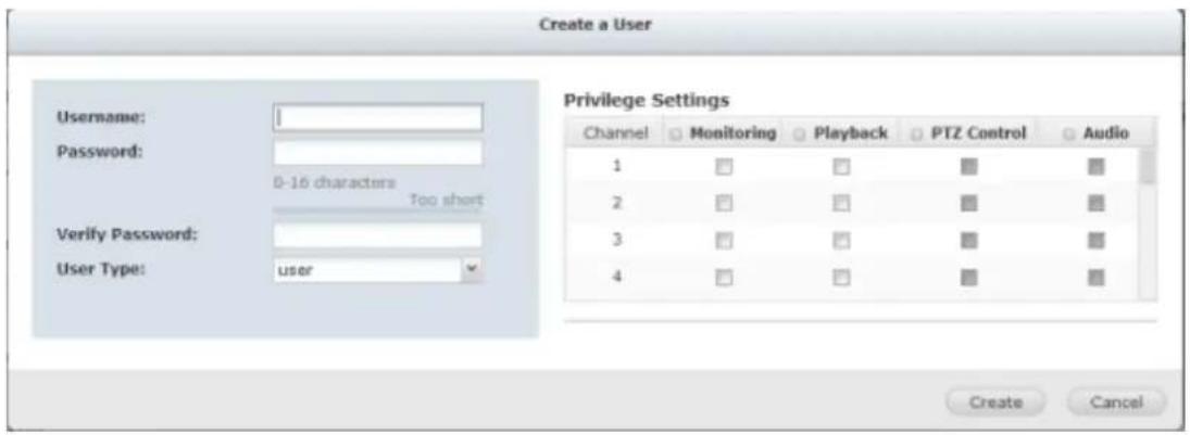
9.3 Network Services
9.3.1 Win
Microso Networking
To allow access to the NVR on Microso Windows Network, enable le service for Microso networking. Specify also how the users will be authenticated.
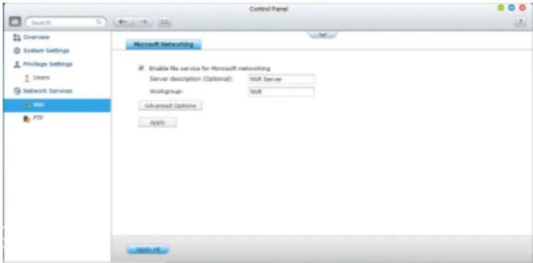
Advanced Opons
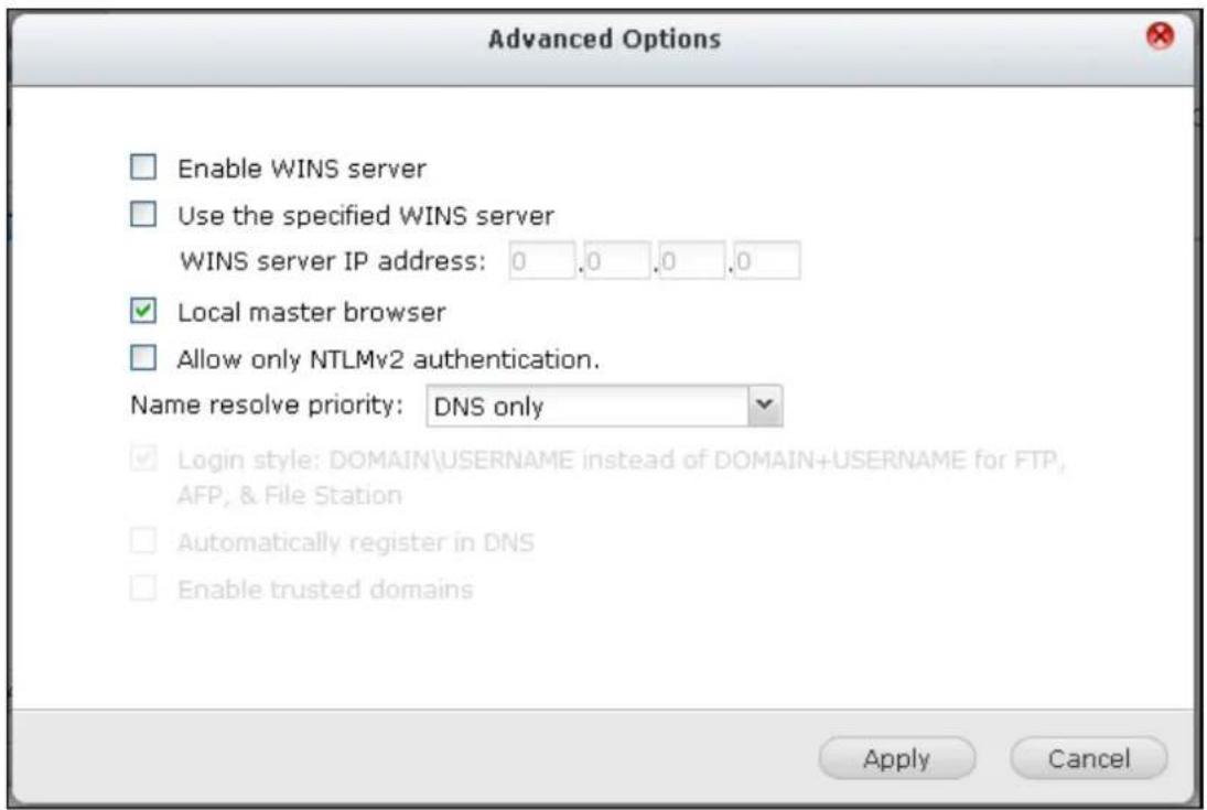
WINS server:
If the local network has a WINS server installed, specify the IP address. The NVR will automacally register its name and IP address with WINS service. If you have a WINS server on your network and want to use this server, enter the WINS server IP. Do not turn on this opon if you are not sure about the sengs.
Local Domain Master:
A Domain Master Browser is responsible for collecting and recording resources and services available for each PC on the network or a workgroup of Windows. When you nd the waing me for connecng to the Network Neighborhood/My Network Places too long, it may be caused by failure of an exisng master browser or a missing master browser on the network. If there is no master browser on your network, select the opon “Domain Master” to conjure the NVR as the master browser. Do not turn on this opon if you are not sure about the sengs.
Allow only NTLMv2 authencaon:
NTLMv2 stands for NT LAN Manager version 2. When this opon is turned on, login to the shared folders by Microso Networking will be allowed only with NTLMv2 authencaon. If the opon is turned o, NTLM (NT LAN Manager) will be used by default and NTLMv2 can be negoated by the client. The default seng is disabled.
Name resoluon priority:
You can select to use DNS server or WINS server to resolve client host names from IP addresses. When you set up your NVR to use a WINS server or to be a WINS server, you can choose to use DNS or WINS rst for name resoluon. When WINS is enabled, the default seng is "Try WINS then DNS". Otherwise, DNS will be used for name resoluon by default.
Login style: DOMAIN\USERNAME instead of DOMAIN+USERNAME for FTP, AFP, and File Staon
In an Acve Directory environment, the default login formats for the domain users are:
- Windows shares: domain\username
- FTP: domain+username
File Staon: domain+username
• AFP: domain+username
When you turn on this opon, the users can use the same login name format (domain\username) to connect to the NVR via AFP, FTP, and File Staon.
Automacally register in DNS: When this opon is turned on and the NVR is joined to an Acve Directory, the NVR will register itself automacally in the domain DNS server. This will create a DNS host entry for the NVR in the DNS server. If the NVR IP is changed, the NVR will automacally update the new IP in the DNS server.
Enable trusted domains: Select this opon to load the users from trusted Acve Directory domains and specify their access permissions to the NVR in “Privilege Sengs” > “Shared Folders”. (The domain trusts are set up in Acve Directory only, not on the NVR.)
9.3.2 FTP
FTP Service
When you turn on FTP service, you can specify the port number and the maximum number of users that are allowed to connect to the NVR by FTP at the same me.
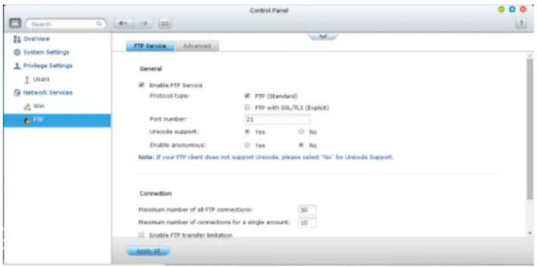
To use the FTP service of the NVR, enable this funcon. Open an IE browser and enter p://NVR IP. Enter the username and the password to login the FTP service.
Protocol Type:
Select to use standard FTP conneccon or SSL/TLS encrypted FTP. Select the correct protocol type in your client FTP soware to ensure successful conneccon.
Unicode Support:
Turn on or o the Unicode support. The default seng is No. If your FTP client does not support Unicode, you are recommended to turn o this opon and select the language you specify in “General Sengs” > “Codepage” so that the le and folder names can be correctly shown. If your FTP client supports Unicode, enable Unicode support for both your client and the NVR.
Anonymous Login:
You can turn on this opon to allow anonymous access to the NVR by FTP. The users can connect to the les and folders which are open for public access. If this opon is turned o, the users must enter an authorized username and password to connect to the server.
Advanced
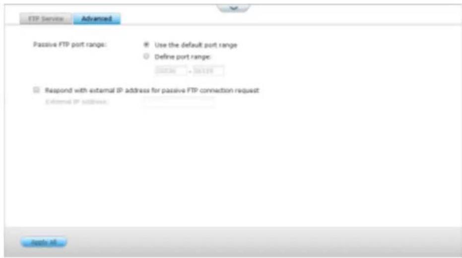
Passive FTP Port Range:
You can use the default port range (55536-56559) or specify a port range larger than 1023. When using this funcon, make sure you have opened the ports on your router or rewall.
Respond with external IP address for passive FTP conncon request:
When passive FTP conncon is in use, the FTP server (NVR) is behind a router, and a remote computer cannot connect to the FTP server over the WAN, enable this funcon. When this opon is turned on, the NVR replies the IP address you specify or automacally detects the external IP address so that the remote computer is able to connect to the FTP server.
10. QNAP Applications
10.1 myQNAPcloud Service
The myQNAPcloud service is a function which provides host name registration, mapping of the dynamic NVR IP to a domain name, and auto port mapping of UPnP router on the local network. Use the myQNAPcloud wizard to register a unique host name for the NVR, configure automatic port forwarding on the UPnP router, and publish NVR services for remote access over the Internet.
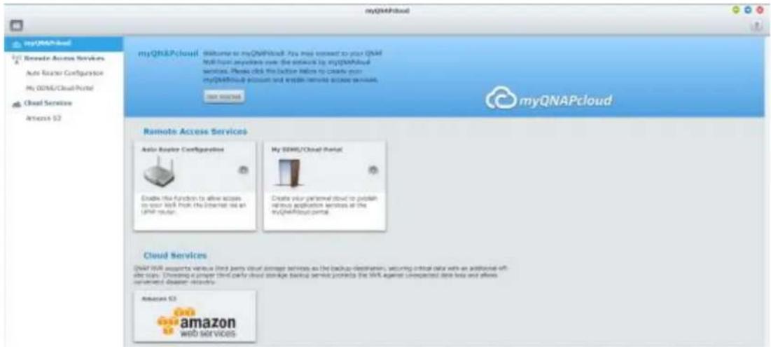
To use the myQNAPcloud service, make sure the NVR has been connected to an UPnP router and the Internet and click the myQNAPcloud shortcut from the NVR Desktop or Main Menu.
10.1.1 Remote Access Services
myQNAPcloud wizard
The first time you use the myQNAPcloud service, you are recommended to use the myQNAPcloud wizard to complete the settings. Follow the steps below:
- Click "Get Started" to use the wizard.
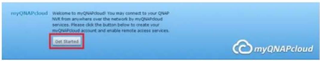
2. Click "Start".
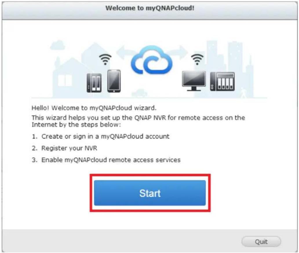
- Please use your myQNAPcloud ID(QID) and password to login. (Click "Create myQNAPcloud account" if you don't have myQNAPcloud account.)
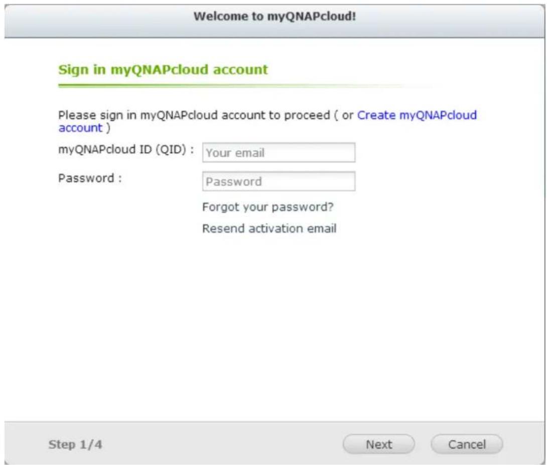
- Enter a name to register your NVR and click "Next".
Welcome to myQNAPcloud!
Register your myQNAPcloud device name
Please enter a name to register your QNAP NVR. This name will be used to access your NVR remotely.
qvrtest
After finishing the wizard, you can access your QNAP NVR remotely with the following Internet address:
qvrtest.myqnapcloud.com
Step 2/4
Next
Cancel
- The wizard will congregate your router automacally.
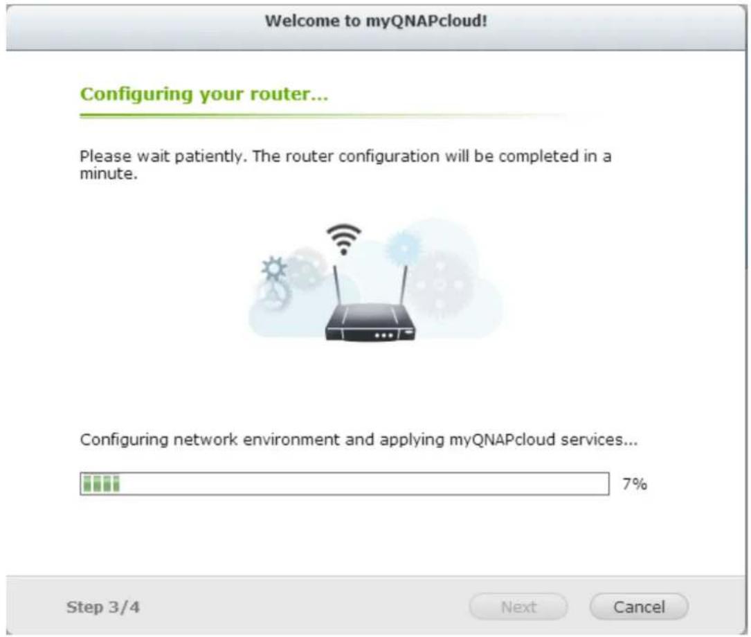
- Review the summary page and click "Finish" to complete the wizard.
Summary
Congratulations! You have completed the following settings. You can now access your QNAP NVR remotely on the Internet.
√ Auto router configuration (UPnP port forwarding)
Setup successfully
myQNAPcloud device name qvrtest
Connect to the QNAP NVR from the myQNAPcloud website (http://www.myqnapcloud.com) by entering the device name, or use the following Internet address: name: qvrtest.myqnapcloud.com
√ Publish NVR services on the cloud portal:
QVR, File Station
Step 4/4
Finish
Manage and configure your myQNAPcloud account
Click "Manage myQNAPcloud Account" on top of the page after launching myQNAPcloud or log into your account at http://www.myqnapcloud.com.


After click your login ID(QID) and password in "Sign in", you can enter your device name in "Enter device name" to search your devices. Or you can select "My Devices" from the drop down menu in left side to review all your device published services and details, including the name, DDNS address, LAN and WAN IP.
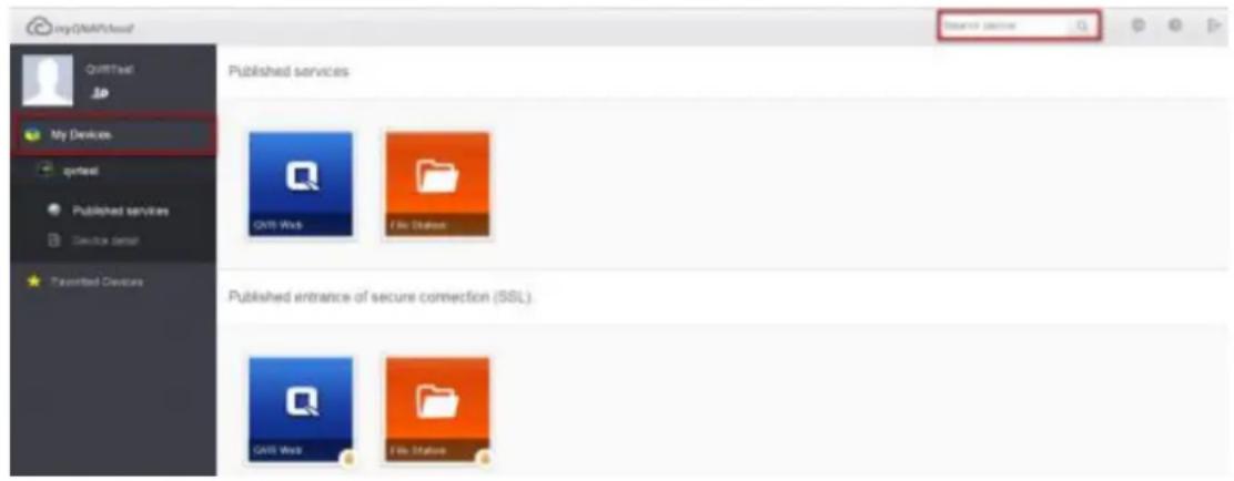
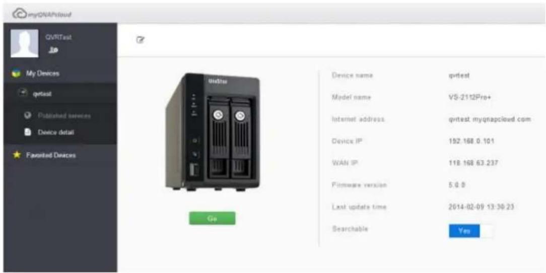
Or, select button "My Account" in top left corner to check your profile, change your password and monitor your account activity.
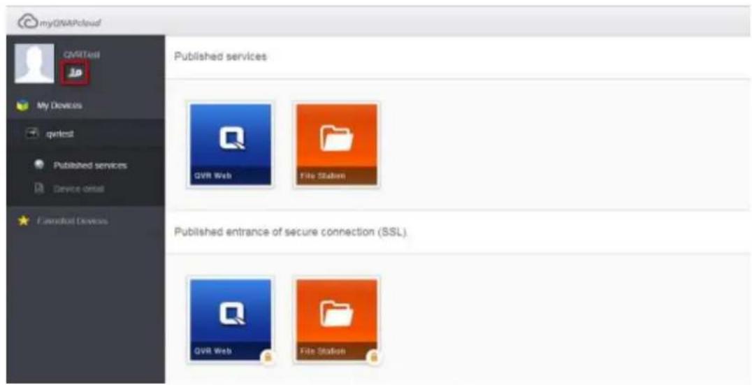
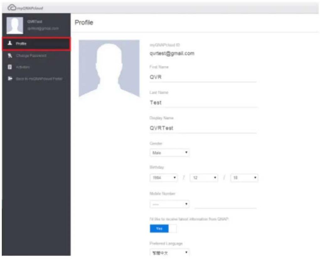
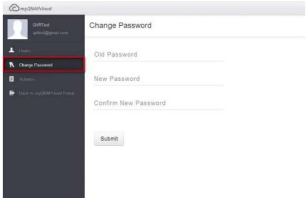
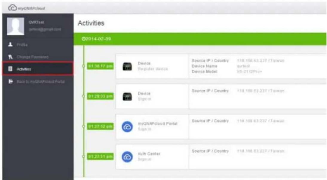
Access NVR services via the myQNAPcloud website
To access the NVR services via the myQNAPcloud website, specify the NVR you registered with in the search box and click search button in the right.

The published public NVR services will be listed.
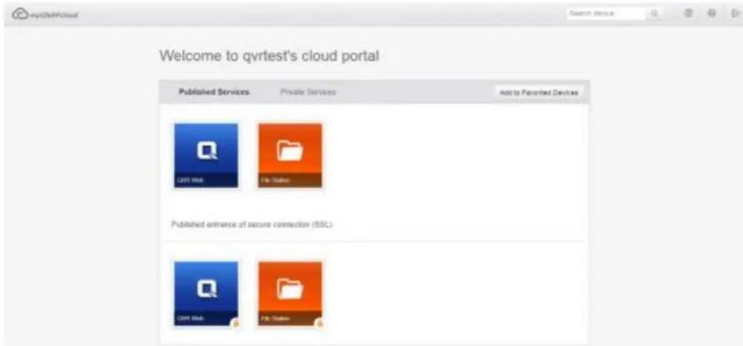
Enter the access code to browse private services.
Private Services
User name
Access code
Confirm
After entering the user name and access code, you can browse private services.
Note: For configuration on private NVR services, please refer to the DDNS/Cloud Portal section later in this chapter.
Auto Router Configuration
In "Remote Access Services" > "Auto Router Configuration", you can enable or disable UPnP port forwarding. When this option is enabled, your NVR is accessible from the Internet via the UPnP router.
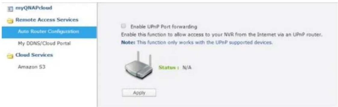
Note: If there is more than one router on the network, only the one which is se as the default gateway of the NVR will be detected.
Click "Rescan" to detect the router if no UPnP router is found on the local network and "Diagnostics" to check the diagnostic logs.
√ Enable UPnP Port forwarding
Enable this function to allow access to your NVR from the Internet via an UPnP router.
Note: This function only works with the UPnP supported devices.
Status: No UPnP router found on the network
Rescan
Diagnostics
Network Diagnostics
---- NAT PMP Diagnostics ----
initnatpmp() returned 0 (SUCCESS)
using gateway:192.168.0.1
sendpublicaddressrequest returned 2 (SUCCESS)
readnatpmpresponseorretry returned -100 (TRY AGAIN)
readnatpmpresponseorretry returned -100 (TRY AGAIN)
readnatpmpresponseorretry returned -7 (FAILED)
---- UPnP Diagnostics
upnpc : miniupnpc library test client. (c) 2006-2011 Thomas Bernard
Go to http://miniupnp.free.fr/ or http://miniupnp.tuxfamily.org/ for more information.
List of UPNP devices found on the network :
desc: http://192.168.0.1:12592/rootDesc.xml
st: urn:schemas-upnp-org:device:InternetGatewayDevice:1
Close
If the UPnP router is incompatible with the NVR, click and then click "UPnP Router Compatibility Feedback..."
(http://www.qnap.com/go/compatibility_router.html) to contact the technical support.
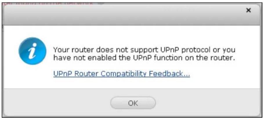
Select the NVR services to be allowed for remote access in section "Forwarded Services". Then click "Apply to Router". The NVR will configure the port forwarding on the UPnP router automatically. You will then be able to access the NVR services from the Internet.
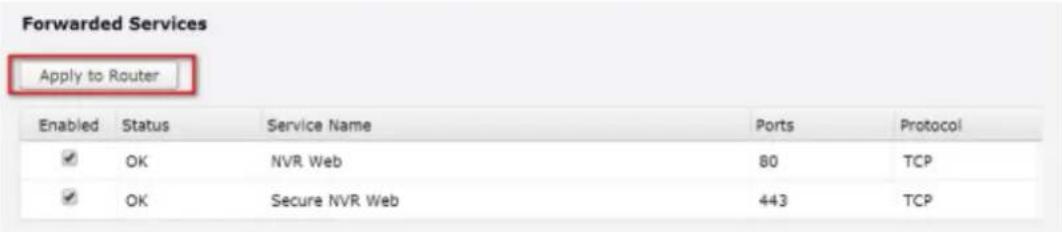
Note:
If more than two NVR are connected to one UPnP router, please specify a dierent port for each NVR. If the router does not support UPnP, users are required to congregate port forwarding manually on the router. Please refer to the links below:
Applicaon note: hp://www.qnap.com/go/notes.html
FAQ: hp://www.qnap.com/faq
UPnP router compatibility list:
hp://www.qnap.com/UPnP_Router_Compatibility_List
My DDNS
With the Cloud Portal, web-based NVR services such as web administration and File Station can be published to http://www.myqnapcloud.com.
By enabling the NVR services in this step, they are opened for remote access even if they are not published.
Enable the My DDNS service in "Remote Access Service" and the NVR will notify the myQNAPcloud server automatically if the WAN IP address of the NVR has changed. To use the myQNAPcloud service, make sure the NVR has been connected to an UPnP router and the Internet.
Note:
- The myQNAPcloud name of each QNAP NVR is unique. One myQNAPcloud name can only be used with one NVR. A registered myQNAPcloud name will expire in 120 days if your NVR remains one within the period. Once the name is expired, it will be released for new registraon by other users.
Cloud Portal
In "Remote Access Services" > "My DDNS/Cloud Portal" > "Cloud Portal", the web-based NVR services are shown. Select "Publish" to publish the NVR services to myQNAPcloud website.
Select "Private" to hide the published NVR services from public access if you don't want every user can access this published NVR service. The private services on the myQNAPcloud website are only visible to specified users with the myQNAPcloud access code.
| NVR Services | Status | Publish | Private |
| NVR Web | Enabled | ☑ | ☑ |
| File Station | Enabled | ☑ | ☑ |
| Secure NVR Web | Enabled | ☑ | ☑ |
| Secure File Station | Enabled | ☑ | ☑ |
Set myQNAPcloud Access Code for private services: Enter a code of 6-16 characters (a-z, A-Z, 0-9 only). The code is required when NVR users attempt to view the private NVR services on the myQNAPcloud website.
myQNAPcloud Access Code
Set the myQNAPcloud Access Code:

Note: The code must be 6-16 characters (a-z, A-Z, 0-9 only).
Note: If a disabled NVR service is published, the service will not be accessible even the corresponding icon is shown on myQNAPcloud website (hp://www.myQNAPcloud.com).
Click "Add Users" and specify maximum 9 local NVR users who are allowed to view the private NVR services published on the myQNAPcloud website.
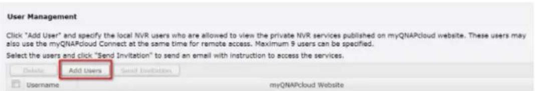
Select the users and connection method: myQNAPcloud website. Click "Apply".
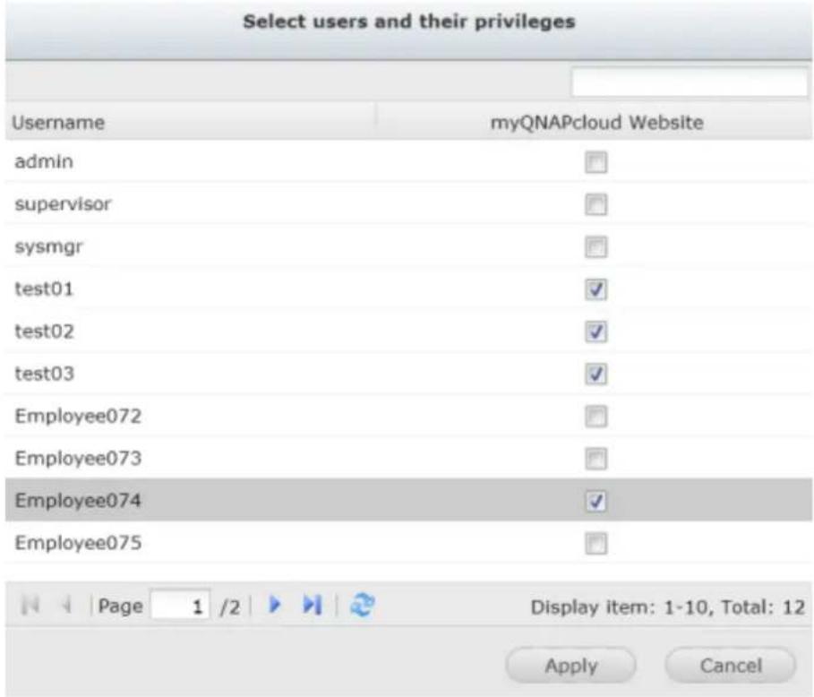
Then click "Apply" to save the settings.
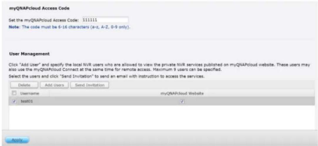
To send the instructions of the myQNAPcloud service to users via email, select the user(s) and click the "Send Invitation" button.
Note: To use this function, the mail server settings must be properly configured in "Control Panel" > "System Settings" > "Notification" > "SMTP Server".
Enter the email address. Click "Send".
| Invite users with email notification to access service | |||
| Username | Status | ||
| test01 | test01@qnap.com | ||
Send
Close
10.1.2 Cloud Services
Amazon S3
Amazon S3 (Simple Storage Service) is an online storage web service provided by Amazon Web Services. QNAP VioStor NVR supports Amazon S3 to allow the users to back up the data from the NVR to Amazon S3, or download it from Amazon S3 to the NVR at anytime. Besides, the users can also create scheduled replicaon job for daily, weekly, or monthly backup.
Create your own Amazon S3 account
To use the Amazon S3 feature on VioStor NVR, follow the steps below:
Step 1: Sign up/ Login Amazon Web Services Account
You need to sign up for Amazon S3 account (hp://aws.amazon.com/s3/). For the price informaon, please refer to the Amazon web services website.

Sign In or Create an AWS Account
You may sign in using your existing Amazon.com account or you can create a new account by selecting "I am a new user."
My e-mail address is:
I am a new user.
I am a returning user and my password is:

Sign in using our secure server
Forgot your password? Has your e-mail address changed?
Learn more about AWS Identity and Access Management and AWS Multi-Factor Authentication, features that provide additional security for your AWS Account.
About Amazon.com Sign In
Amazon Web Services uses information from your Amazon.com account to identify you and allow access to Amazon Web Services. Your use of this site is governed by our Terms of Use and Privacy Policy linked below.
Terms of Use | Privacy Policy © 1996-2014, Amazon.com, Inc. or its affiliates An amazon.com. company
Step 2: Get Your Access Key ID and Secret Access Key
Once you have successfully signed up an account, you will receive your Access Key ID and Secret Access Key. Please keep your ID and key safe.
If you have missed the Access Key ID and Secret Access Key notification, click "Your Account" and
choose "Security Credentials" to retrieve them.
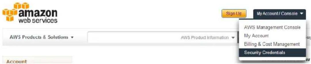
Check your Access Keys (Access Key ID and Secret Access Key). Click "Create New Access Key" if you don't have Access keys.
Your Security Credentials
Use this page to manage the credentials for your AWS account. To manage credentials for AWS identity and Access Management (IAM) users, use the IAM Console. To learn more about the types of AWS credentials and how they're used, see AWS Security Credentials in AWS General Reference.
- Password
Multi-Factor Authentication (MFA)
Access Keys (Access Key ID and Secret Access Key)
Note: You can have a maximum of two access keys (active or inactive) at a time.
Created
Feb 16th 2014
Deleted
Access Key ID
Status
Active
Actions
Make Inactive | Delete
Create Remote Replication Job on Amazon S3
For using Remote Replicaon Job on Amazon S3, you must have one Amazon S3 account rst. You can refer to secon "Create your own Amazon S3 account" for detailed informaon.
You can back up the NVR data to or retrieve the data from the Amazon S3. Amazon's services will generally accept requests that are received within 15 minutes after you login Amazon S3. Before getting started, make sure your system clock is set correctly according to your time zone. It is suggested to configure your NVR to automatically synchronize with the system clock using the Network Time Protocol (NTP).
Follow the steps below to create a remote replication job on Amazon S3.
Step 1: Login your VioStor NVR and go to "myQNAPcloud" > "Cloud Service" > "Amazon S3". Click "Create New Replicang Job".
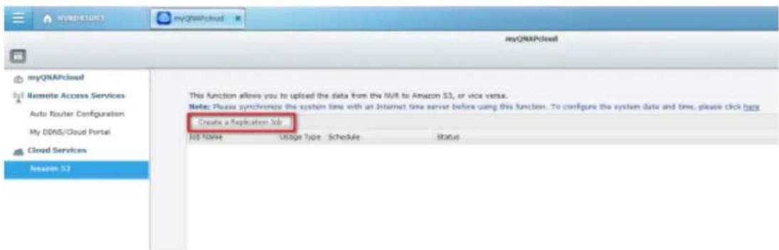
Step2: Enter the job name.
Create a Replication Job
Remote Replication Wizard
This wizard helps you create a remote replication job.Enter the name of the remote replication job and click Next.
Remote Replication Job Name:
Step 1/5
Next
Cancel
Step3: Select usage Type (Upload or download) from the dropdown menu. Then input the access key, private key and remote path. A bucket is the root directory on Amazon S3. You can do remote host tesng by clicking "TEST". Other sengs are oponal.
Note: To use this function, you must create at least one Bucket on Amazon S3. Please go to Amazon S3 on website and select "Create Bucket" to create one Bucket on your Amazon S3 account.
Create a Replication Job
Amazon S3
Usage Type:
Upload

Access Key:
AKIAJ4TC2PUP34CC63FC
Secret Key:
Remote Path
qnapqvrtest
test
(Bucket/Directory):
Remote Host Testing:
Test
Maximum number of retries (0-99):
10
Maximum upload rate (KB/s):

☐ Perform incremental replication
Delete extra files on remote destination
√ Enable Server Side Encryption

Enable Reduced Redundency Storage

Step 2/5
Back
Next
Cancel
Step4: Specify the local path as Network Share/ Directory. Select the network share from dropdown menu and input the directory.
Create a Replication Job
Local Path
Please specify: Local Path (Network Share/Directory):
mp4

20140214
Step 3/5
Back
Next
Cancel
Step5: Specify your replicaon schedule.
Create a Replication Job
Replication Schedule
Select schedule:
Replicate Now
Daily
Weekly
Monthly
Time
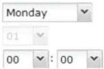
Step 4/5
Back
Next
Cancel
Step6: Click "Finish" to complete the setup.
Setup complete
The remote replication settings have been completed. Click Finish to exit the Wizard.
Step 5/5
Finish
Upon successful job creation you will see the status of the replication job(s). You can edit or delete them if necessary.
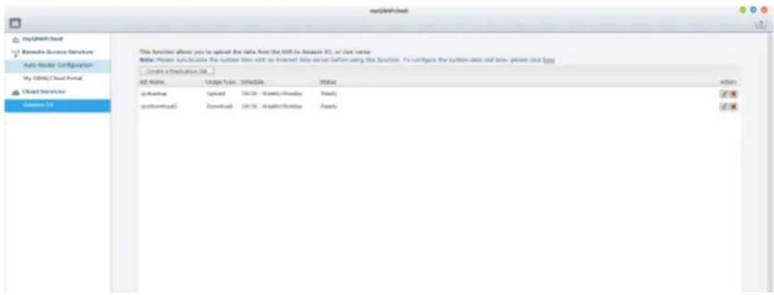
10.2 File Station
The File Staon allows the users to access the NVR on the Internet and manage the les by a web browser.

| Number | Item | Descripon |
| 1 | Search | Search by name, type(music, movie, photo...) or select advanced search |
| 2 | View mode | Change the View mode |
| 3 | Create folder | Create a folder in shared folders |
| 4 | Copy | Copy/ Paste les and folders |
| 5 | Upload | Select the folder to upload the le to |
| 6 | Share | Share a le or folder with other users using various methods |
| 7 | More Acon | Add the shared folders to bookmark |
| 8 | Refresh | Refresh this page |
| 9 | Sengs | • Show les and folders of my PC• Show hidden les |
Before geng started
Enable the service in "Control Panel" > "Applicaons" > "Staon Manager". Click the link on the page to access the File Staon.
The File Staon can be launched from the Main Menu or the File Staon icon on the Desktop.
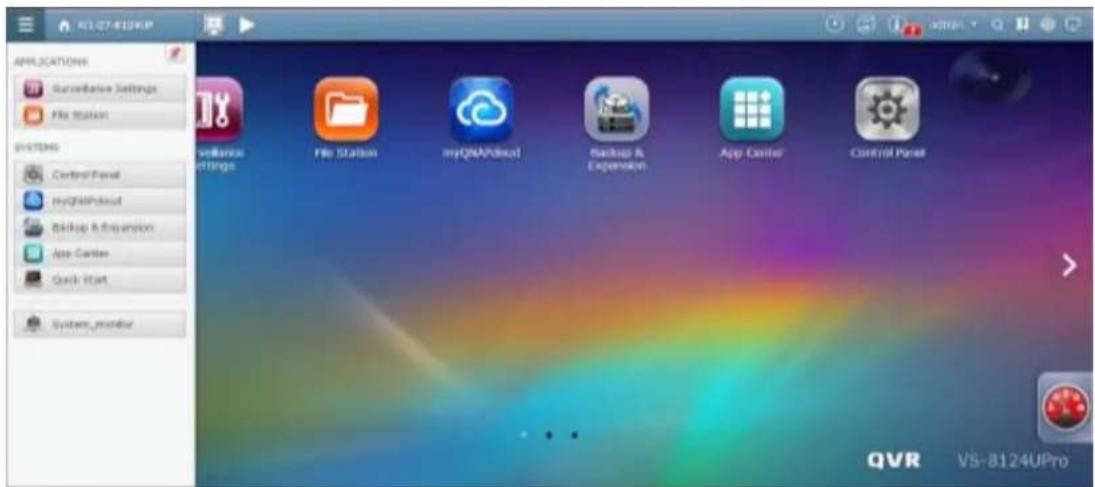
You can upload, download, rename, move, copy, or delete the les and folder on the NVR.
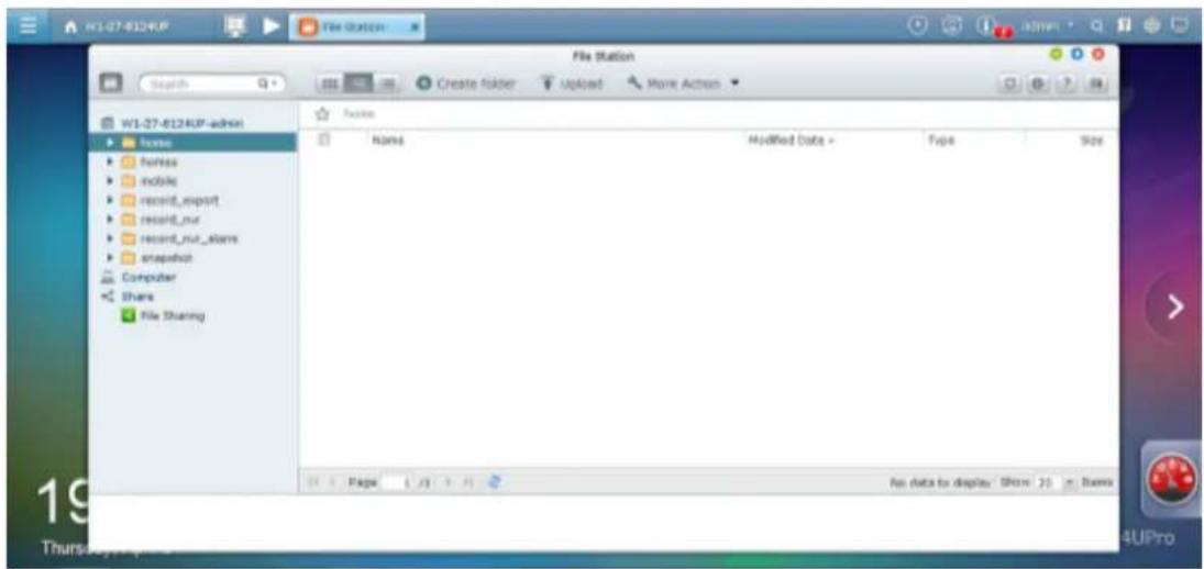
Uploading les
To use this feature, install Adobe Flash plug-in for your web browser.
- Select a folder and click .
- Click "Browse" to select the le(s).
- Select to skip or overwrite the exisng le(s) in the folder.
- Click 🏠 to upload a le or "Upload All" to upload all the selected les.
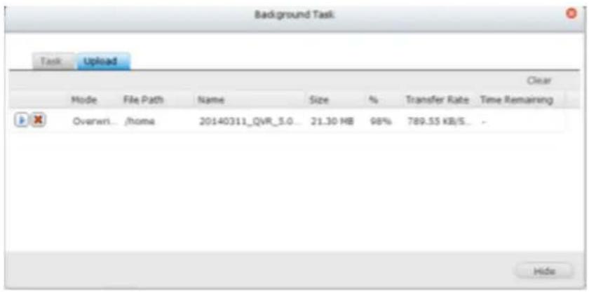
Note: The maximum size of a le that can be uploaded to the NVR by the File Staon is 2GB without JAVA plug-in.
Downloading les
- Select a le or folder to download.
- Right click the mouse and select "Download" to download the le. Please note that if all les within a folder are selected, they will be compressed and downloaded as a zip le.
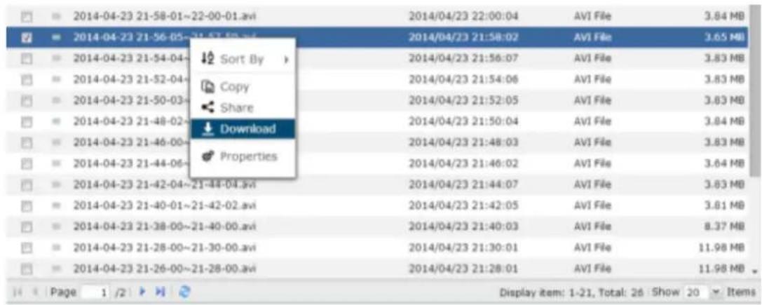
Creang folders
- Select a shared folder or folder in which you want to create a new folder.
- Click . Create folder
- Enter the name of the new folder and click "OK".
Renaming les or folders:
- Select a le or folder to rename.
- Right click the mouse and select "Rename" to rename the le.
- Enter the new le or folder name and click "OK".
Copying les or folders
- Select the les or folders to copy.
- Click .
- Click the desnaon folder.
- Click and conrm to copy the les or folders.
Moving les or folders
- Select the les or folders to move.
- Right click the mouse and select "Move".
- Select the desnaon folder. Click "OK".
Deleng les or folders
- Select a le or folder to delete.
- Right click the mouse and select "Delete".
- Conrm to delete the le or folder.
File/Folder search
The File Staon supports smart search of les, sub-folders, and folders on the NVR. You can search a le or folder by all or part of the le or folder name, or by the le extension.
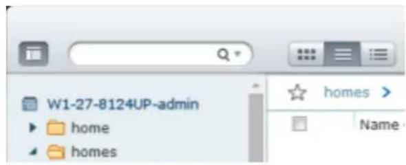
10.3 App Center
The App Center is a digital plaorm for distribuon of NVR apps. Users can search for, install, remove and update apps developed by QNAP or third party apps through the App Center to expand the services and add new features on the NVR.

Starng App Center
The App Center can be launched from the App Center shortcut on the Main Menu or the QVR Desktop.
Familiarizing yourself with App Center
Menu Bar
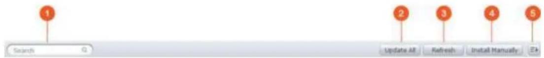
| No | Name | Descripon |
| 1 | Search Bar | Search apps that are available to install on the NVR. |
| 2 | Update all | Update all apps that are currently installed on the NVR. |
| 3 | Refresh | Refresh the current page |
| 4 | Install Manually | Browse to upload and install a QPKG add-on manually. |
| 5 | Sort | Sort apps by category, name or release date. |
Le Panel
• My Apps: List apps that are currently installed on the NVR.
- All Apps: List all apps that can be installed on the NVR.
Using App Center
Searching apps
To search for an app, enter the keyword in the search bar.
Installing, updang and removing apps
To install an app, click the "Add to QVR+" buon and the installaon process will begin. Aer the installaon process is complete, the "Add to QVR+" buon will turn to the "Open" buon and you can directly click this buon to launch this newly installed app. This newly installed app will then show up in "My Apps".
Note:
• Make sure the NVR is connected to the Internet.
- QNAP is not responsible for troublesomeng any issues caused by the open source soware/add-ons.
- When installing an add-on which requires a prerequisite app, the prerequisite add-on will be added to the installaon queue automacally prior to the dependent add-on.
- If the app update process is canceled before it is nished, please install the app from the App Center again.
To update an app, click "Update" and click "OK" to conrm. Alternatively, you may click "Update All" on the menu bar to install all updates and "Refresh" to check for the latest updates. The buon will turn to "Open" to signify that the update is complete for an app. To remove an app, rst click an installed app to open its introducon page. Click "Remove" on the page to uninstall it from the NVR and click "OK" to conrm.
Note:
- Click the on/o buon in an app icon to enable or disable an app.
Oine Installaon
To install apps when the NVR is oine or beta apps that are not socially available on the QNAP App server, users can download the app applicaon (*.qpkg) from the QNAP security website (hp://www.qnapsecurity.com/) or forum (hp://forum.qnapsecurity.com/index.php), unzip the les, and click "Install Manually" on the menu bar to install the apps manually.
11. QNAP Surveillance Central Management (QSCM Lite)
11.1 Introduction
QNAP Surveillance Central Management Lite (referred to as “QSCM Lite” in the following context) is a pioneering, powerful and free App supported by QNAP VioStor NVR (with rmware QVR 5.0 and above), that turns your NVR into a CMS server to manage up to 16 QNAP NVRs and 256 cameras.
No extra investment in hardware or soware is required to add CMS server funcon to a NVR – all you have to do is install the QSCM Lite App.
QSCM Lite can manage NVRs that are in the same private LAN with QSCM Lite.
11.2 Install QSCM Lite to NVR Server
11.2.1 App Center
To install QSCM Lite, please download it from the QVR 5.0 App Center. For more informaon about the App Center, please refer to Secon 10.3 App Center.
11.2.2 How to Install QSCM Lite to NVR Server
Online installation
To install QSCM Lite, please download it from the QVR 5.0 App Center. Your NVR must be connected to the Internet to use the App Center.
Step 1: Go to the App Center on the desktop of QVR 5.0.

Step 2: Go to All Apps.

Step 3: Click "Add QSCM Lite to QVR"
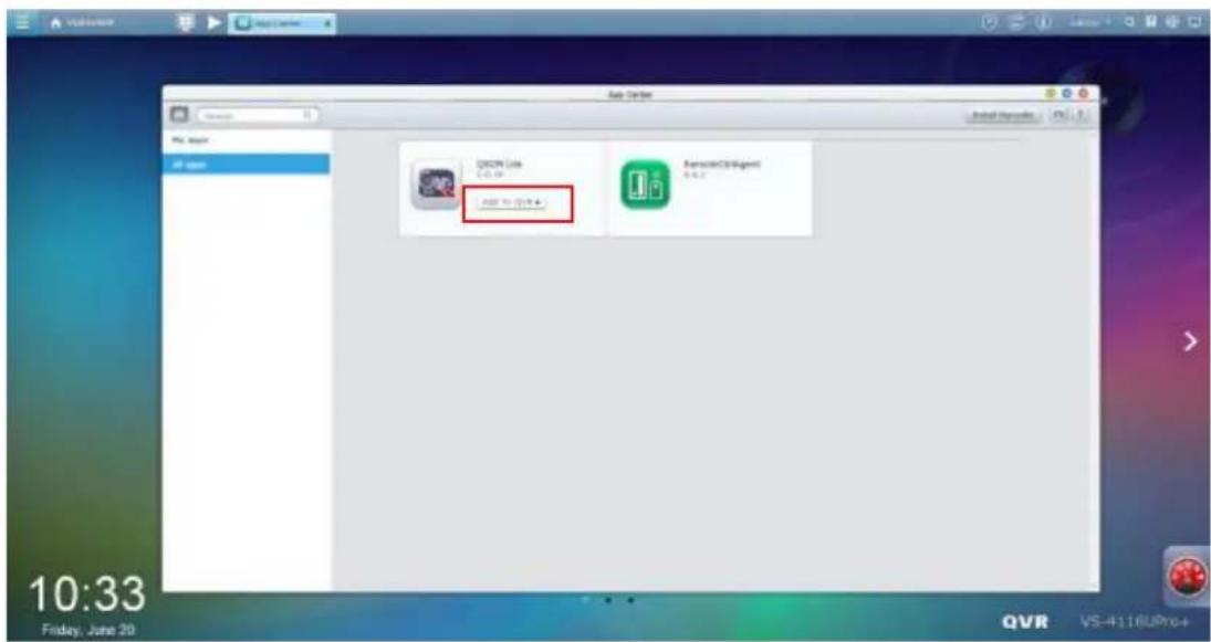
Step 4: Start downloading QSCM Lite

Step 5: Aer QSCM Lite has been downloaded, the system will automatically install QSCM Lite.
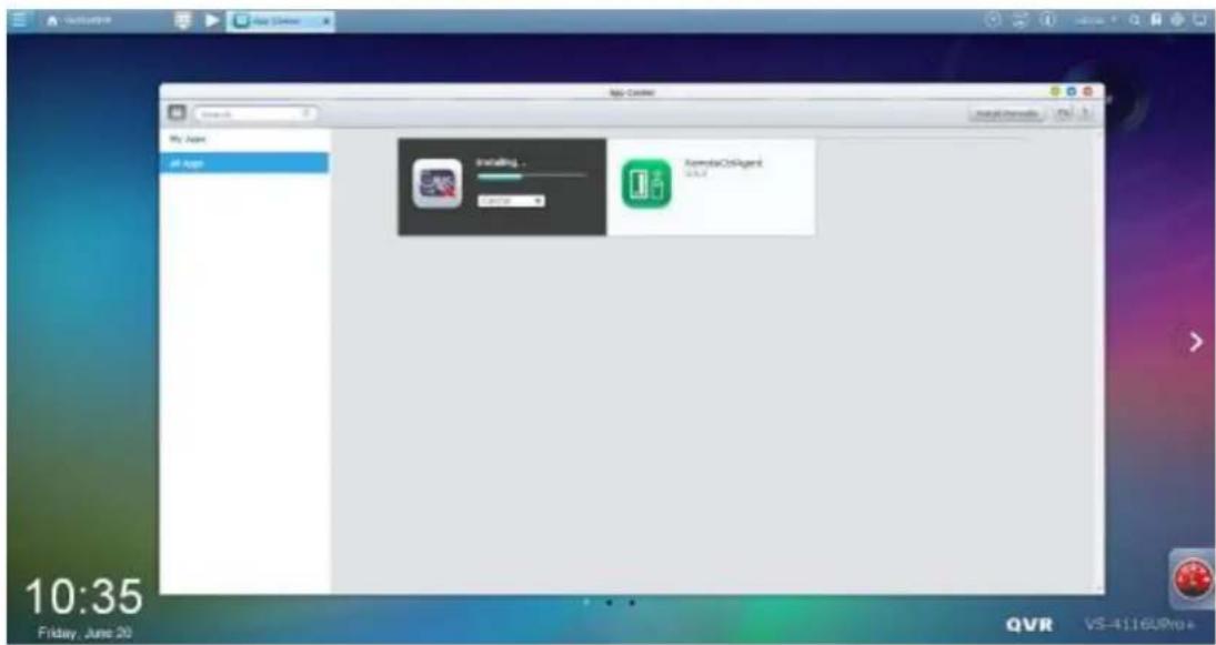
Step 6: When the opon to "Open" appears, QSCM Lite has been successfully installed.

Step 7: QSCM Lite will now be listed in My Apps, with the default Open status. QVR 5.0 is now a CMS server.

QSCM Lite can be turned o to disable the CMS server funcon if needed.

Offline installation
If the NVR is not connected to the Internet, an oine installaon is available.
Step 1: Download QSCM Lite from the QNAP Security website (hp://www.qnapsecurity.com/download.asp).
Step 2: Unzip the les
Step 3: Return to the NVR and enter the App Center
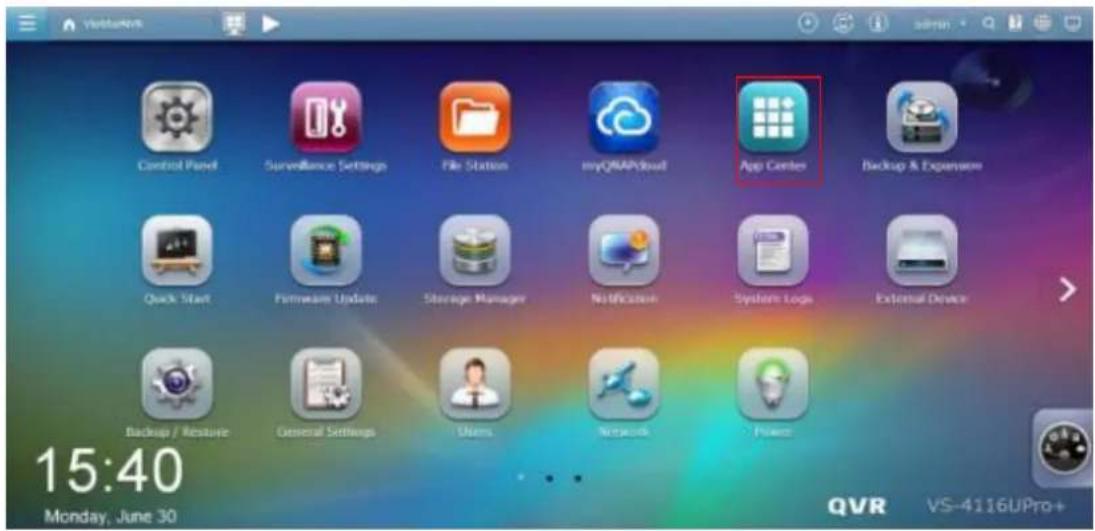
Step 4: Click "Install Manually"
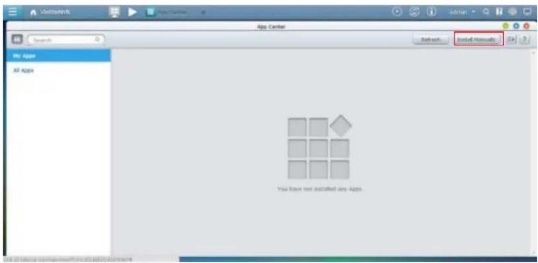
Step 5: Find the unzipped QSCM Lite, and click [Install]
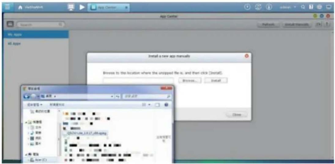
Step 7: The NVR will then install QSCM Lite
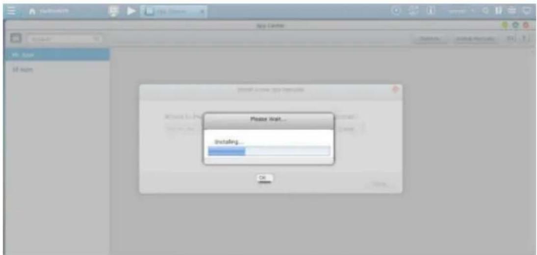
Step 8: Click OK
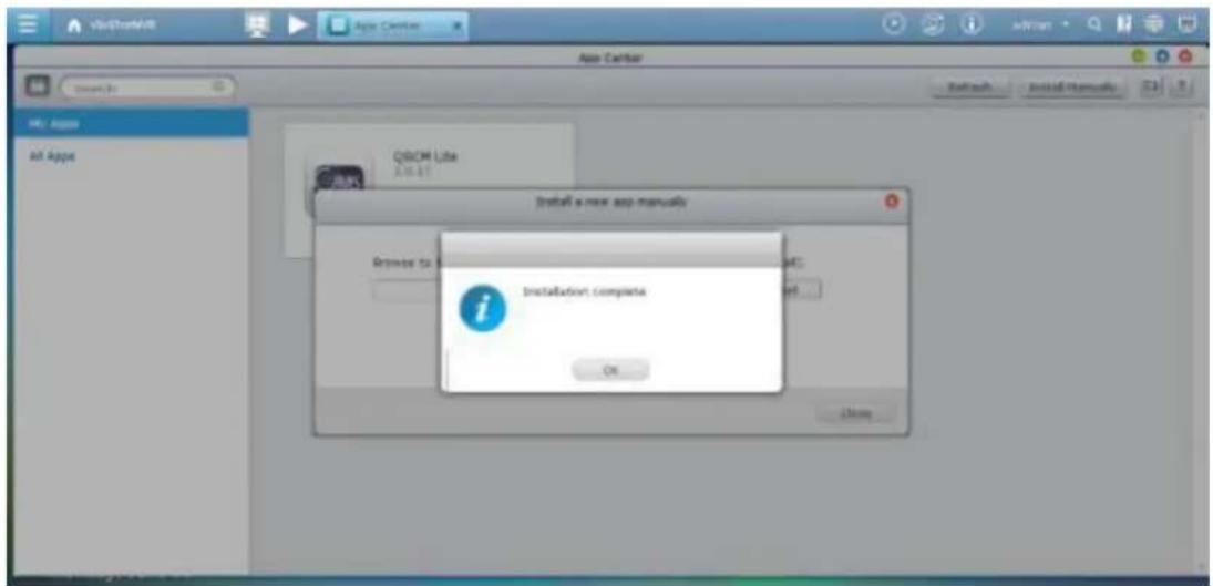
Step 9: QSCM Lite will now be listed in My Apps, with the default Open status. QVR 5.0 is now a CMS server.
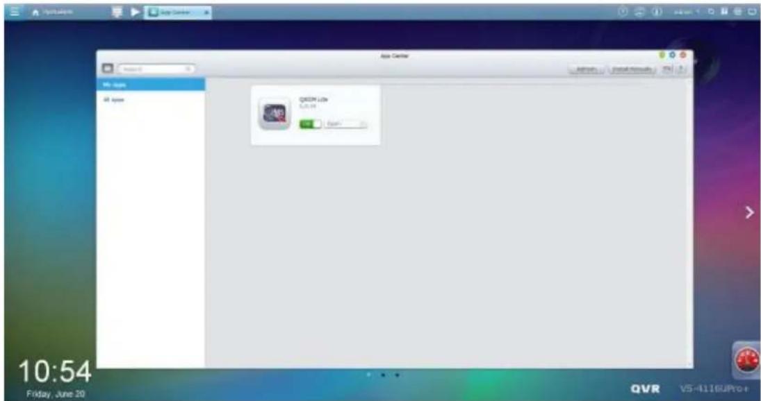
If needed, QSCM Lite can be turned o to disable the CMS server funcon.
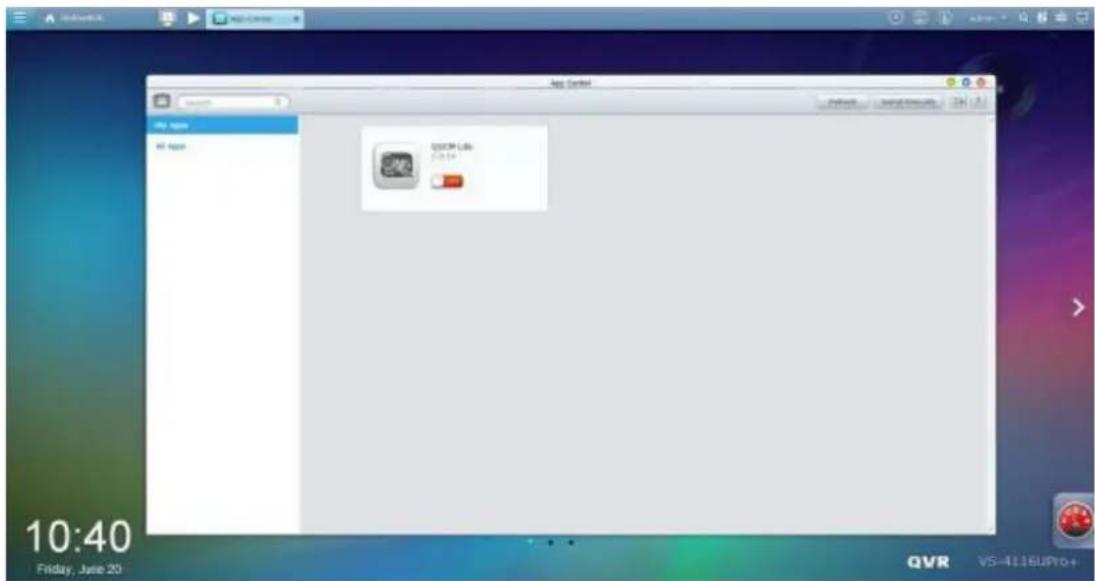
11.2.3 Installation Reminders and Suggestions
- QSCM Lite can only be installed to QNAP NVR with rmware version 5.0 or above.
-
When enabling QSCM Lite on QVR 5.0, you have 2 opons:
-
Do not record camera footage to this server, and have it act as a pure CMS server.
- Keep recording camera footage to this server, and have it act as both a CMS and NVR server simultaneously.
In the second case (the server will act as both a CMS and NVR server simultaneously), the server's hardware resources will be shared by the NVR server service & the CMS server service. If the CPU usage rate is more than 80%, or when the throughput is busy, the performance of both the NVR server and CMS server will be impacted.
- It is strongly recommended to enable just one QVR 5.0 as QSCM Lite to centrally manage the NVRs in a LAN. Otherwise, the QSCM Lite event management (including the live view event nocaon and event log) will be scaered to mulple QSCM Lites.
11.3 Use QSCM Lite on NVR Client PC
11.3.1 How to use QSCM Lite on NVR client PC
Step 1: Connect to a QVR 5.0 with QSCM Lite. For instrucons on how to install QSCM Lite, please refer to 1.2.2.
Step 2: Go to the App Center on the QVR 5.0 desktop.
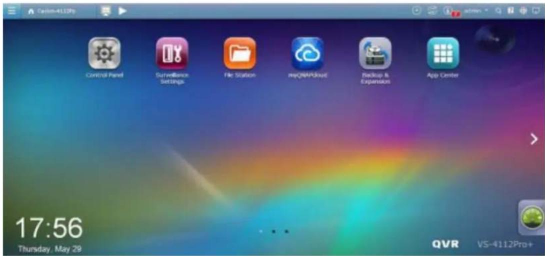
Or, the Main Menu of QVR 5.0
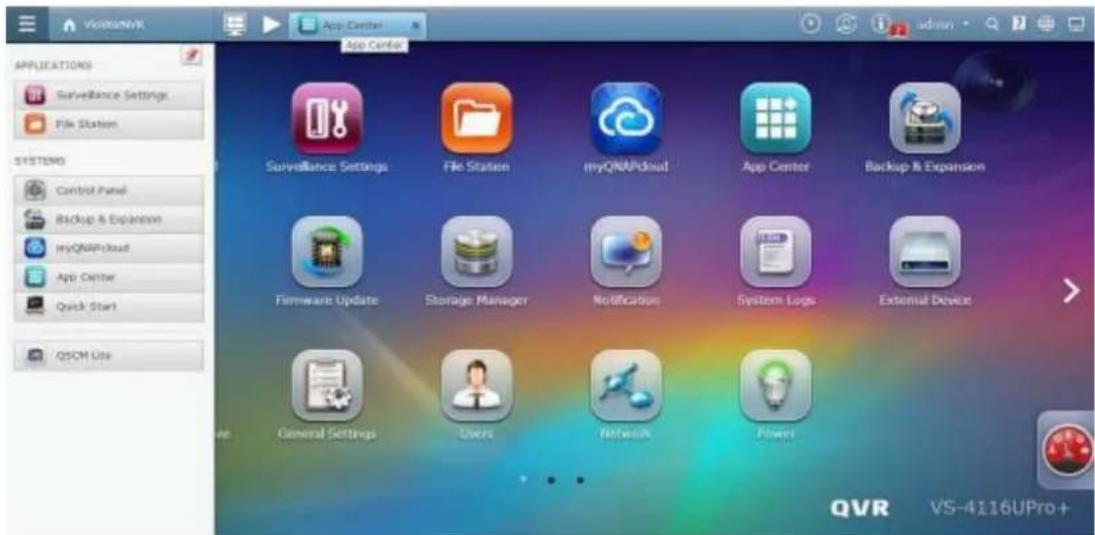
Step 3: Click on the QSCM Lite icon to go to the QSCM Lite login page
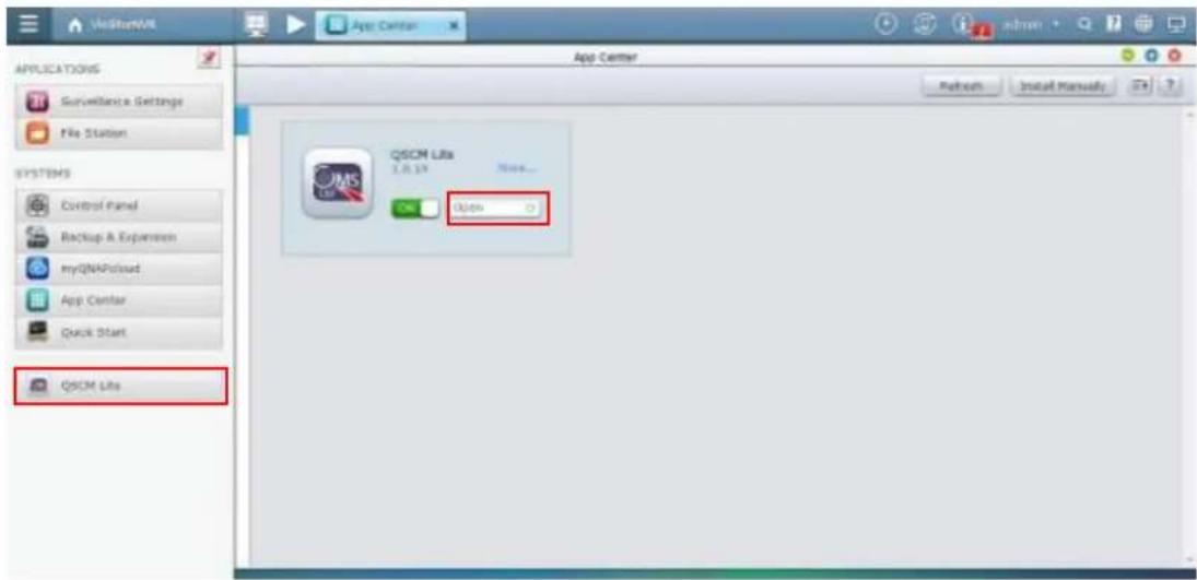
Step 4: The system will automatically redirect to the QSCM Lite login page, and you can log in by using the default username/password (admin/admin).

Step 5: The rst page you will see aer logging into QSCM Lite is the live view page. Before you have congured QSCM Lite, no camera feedback will be displayed.

Step 6: To congure QSCM Lite, go to the conguraon page.
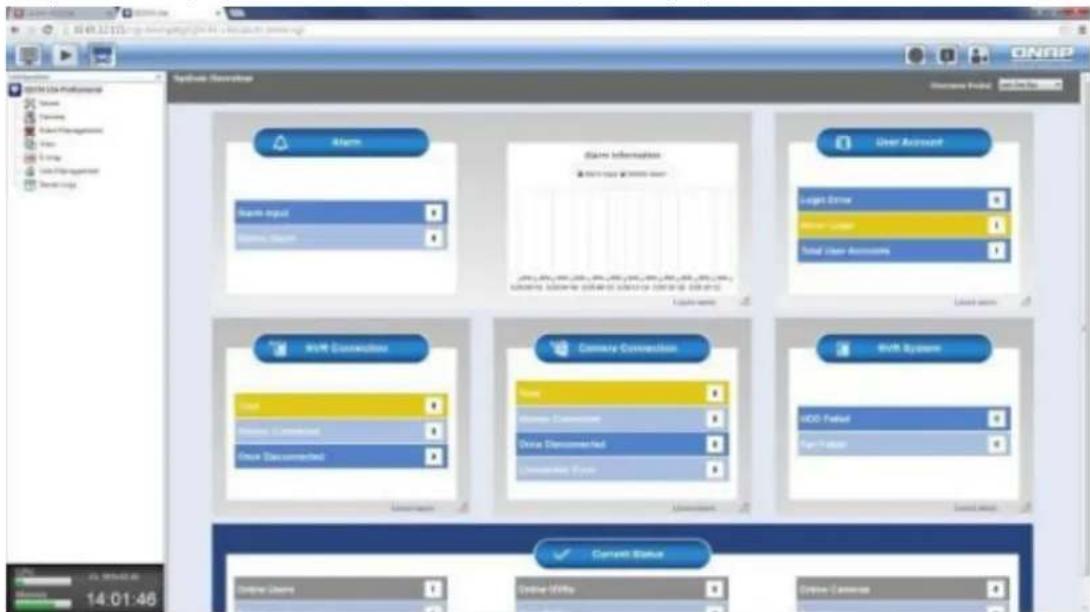
Step 7: For how to congregate QSCM Lite, please refer to Secon 3.5 Congure CMS Client of the VioStor CMS user manual.
Note:
- VioStor CMS is a high-performance turnkey CMS soluon. The CMS Server supports up to a maximum of 128 mul-server monitoring and management. Users can monitor up to a maximum of 1,024 IP cameras with up to 64 channels per screen. Concurrent independent playback and display controls in four screens are also supported. The CMS Server has the highest compatibility with
the QNAP VioStor NVR series and also supports a variety of brand-name IP cameras.
For detailed VioStor CMS informaon, please refer to:
hp://www.qnapsecurity.com/pro_detail_featurecms.asp?p_id=273
11.3.2 Usability Reminder and Suggestions
- If you have the server performing as both a CMS and NVR server simultaneously, it is strongly recommended to open just one live view page (either QVR 5.0 live view or QSCM Lite live view) at the same me. Otherwise, the CPU and throughput usage of the client PC will double.
- For client PC requirements, please refer the Secon 2.1 Personal Computer Requirements of this user manual.
11.3.3 QSCM Lite Client Specification
- The QSCM Lite client specicaon is mostly synchronized with the VioStor CMS client specicaon.
- The specicaon difference between the QSCM Lite client & VioStor CMS client is subject to change without prior nocaon.
11.4 Comparison between VioStor CMS & QSCM Lite
| Comparing Items | QSCM Lite (App/QPKG) | VioStor CMS |
| Working Type | CMS soluon on QNAP VioStor NVR (with rmware QVR 5.0 and above) | Standalone CMS server |
| Manageable NVR | NVR 4.1 (and above) | NVR4.1 (and above) |
| Number of NVRs supported | 16 | 128 |
| Maximum number of channel supported | 256 | 1,024 |
| Number of monitors supported | 4 | 8 |
| Maximum number of client registraon | 32 | Unlimited |
| Key Feature | Mul-Server Enhancement | Centralized Monitoring and Management |
- The QSCM Lite client specicaon is mostly synchronized with the VioStor CMS client specicaon
- The specicaon difference between the QSCM Lite client & VioStor CMS client is subject to change without prior nocaon.
12. Qstart
12.1 Introduction
Qstart brings two leading-edge innovave features: system inializaon and network switch control. It simplifies system inializaon through automacally assigning default sengs with just a single click. By integrang supported switches, Qstart provides comprehensive network topology and a device list for users to fully manage network health and device status. Qstart integrates the major funcons of PoE switches so users can easily setup camera IPs, manage PoE status and monitor trac ow from the VioStor soware (QVR). The intuitive GUI also allows for precise failure detecon and ecient troublesomeong. Qstart provides users with a refreshing experience when installing and remotely maintaining NVRs.
12.2 Before Using Qstart
- All devices including IP cameras, Client PCs, a QNAP VioStor should be connected to the same PoE switch. (VioStor now only supports the scenario of one PoE switch, please avoid cascade PoE cases.)
- Do not set your device to a stac IP, including the client PC and the VioStor NVR, DHCP sengs only.
- All IP cameras must be set to default for Qstart inializaon.
12.3 System Initialization
To use Qstart, please ensure your inserted hard drives are unallocated.
- Please ensure that you use a supported switch and a VioStor model (please check the compatibility list for more informaon).
- Find the VioStor's IP address via QNAP nder.
- Connect to the QVR web-based administration page and select Qstart.
Welcome
Thank you for choosing QNAP viostor NVR. Please click
"Manual Setup" below to start installation.
The installation process should take about 10-15 minutes.
depending on the size of your hard drives.
Note: Website installation is for ViStar NVR servers that
already have hard drives installed.

Manual Setup
Quick Setup
Qstart
Ostart
Provides users with a quick & easy NVR installation experience.
Everything related to the initial setup will be automatically processed in a single click.
- VioStor will detect if there is a DHCP server on the same LAN.
If a DHCP server is detected, it will proceed to the Quick Setup page.
If not, users will be asked to enable the NVR's DHCP server to start inializaon.
Users can enable the DHCP server by selecng Yes.
- TThe Quick Setup page includes basic informaon for both the NVR and devices connected to the switch (including the me zone, name, IP, Disk conguraon, and more.) Conrm that this informaon is correct and proceed to complete the inializaon.

Quick Setup
Please review the following settings and click "Proceed" to continue. Don't worry! You can modify these settings later on the NVR administration page.
NVR Name: NVRDFDDB8
Username: admin
Password: ***** (Default password : admin)
IP Address: (DHCP)
Time Zone: (GMT+08:00) Taipei
Date / Time: 2014/08/13 15:3:26
Disk Configuration: Single (Found 1 Disks, Total Storage Capacity: 465.76 GB)
Bad Block Scan: No
CAMERA: Auto configure
Proceed
Cancel
QNAP
VS-6120Pro+
English

Quick Setup
(1) 2017年1月1日
©
| Channel | Brand | Model | IP Address | MAC Address | |
| √ | 1 | Panasonic iPro | Panasonic iPro SF334 | 169.254.101.191 | 08:00:23:90:b5:86 |
| √ | 2 | Vivotek | VivoTek FD7160 | 169.254.101.200 | 00:02:d1:0a:44:c3 |
| √ | 3 | Sony | Sony SNC-DS10 | 169.254.101.183 | 00:1d:ba:4f:5e:8d |
| √ | 4 | Vivotek | VivoTek IP8362 | 169.254.101.196 | 00:02:d1:11:28:43 |
| √ | 5 | Sony | Sony SNC-VB600B | 169.254.241.77 | 3c:07:71:1e:36:98 |
| √ | 6 | Sony | Sony SNC-VB630 | 169.254.85.251 | 54:53:ed:f9:19:1e |
| √ | 7 | Vivotek | VivoTek FD8136 | 169.254.101.198 | 00:02:d1:18:2d:8d |
| √ | 8 | Sony | Sony SNC-EM630 | 169.254.206.87 | d8:d4:3c:13:97:19 |
| √ | 9 | Panasonic iPro | Panasonic iPro SF135 | 169.254.101.184 | 08:00:23:96:33:5d |
| √ | 10 | Sony | Sony SNC-EB600B | 169.254.49.192 | d8:d4:3c:38:63:6e |
| √ | 11 | ACTi | ACTi D61 | 169.254.101.197 | 00:0f:7c:0a:95:57 |
| √ | 12 | Sony | Sony SNC-CS20 | 169.254.101.185 | 00:1d:ba:3f:e3:ed |
| √ | 13 | Panasonic iPro | Panasonic iPro SW152 | 169.254.101.186 | 08:00:23:95:a4:8e |
| √ | 14 | Vivotek | VivoTek PD8136 | 169.254.101.199 | 00:02:d1:1c:07:0a |
| √ | 15 | ACTi | ACTi D11 | 169.254.101.192 | 00:0f:7c:09:21:20 |
| √ | 16 | ACTi | ACTi E31 | 169.254.101.190 | 00:0f:7c:09:78:19 |
| √ | 17 | Panasonic iPro | Panasonic iPro SP102 | 169.254.101.194 | 08:00:23:95:a6:a7 |
| √ | 18 | ACTi | ACTi E41 | 169.254.101.193 | 00:0f:7c:09:ae:bf |
| √ | 19 | Axis | Axis P1357 | 169.254.101.188 | ac:cc:8e:03:05:d9 |
| √ | 20 | Axis | Axis P1355 | 169.254.101.187 | 00:40:8cf:4:cd:d8 |
Proceed
Cancel
Please note:
- Users cannot modify network sengs (DHCP/Stac) in Qstart mode.
- The channel number is based on the port number of the switch. (For example, if a VS-2112 Pro+ connects to a 24-port switch, the table will show channel 1 to channel 24 regardless of the NVR's supported channels.)
-
Default sengs:
-
Selects all supported cameras that are connected to the switch.
-
Auto congure
-
Enter the QVR desktop. The camera overview page and QVR introducon page will appear simultaneously. (The camera overview in front, and the QVR introducon behind it.)
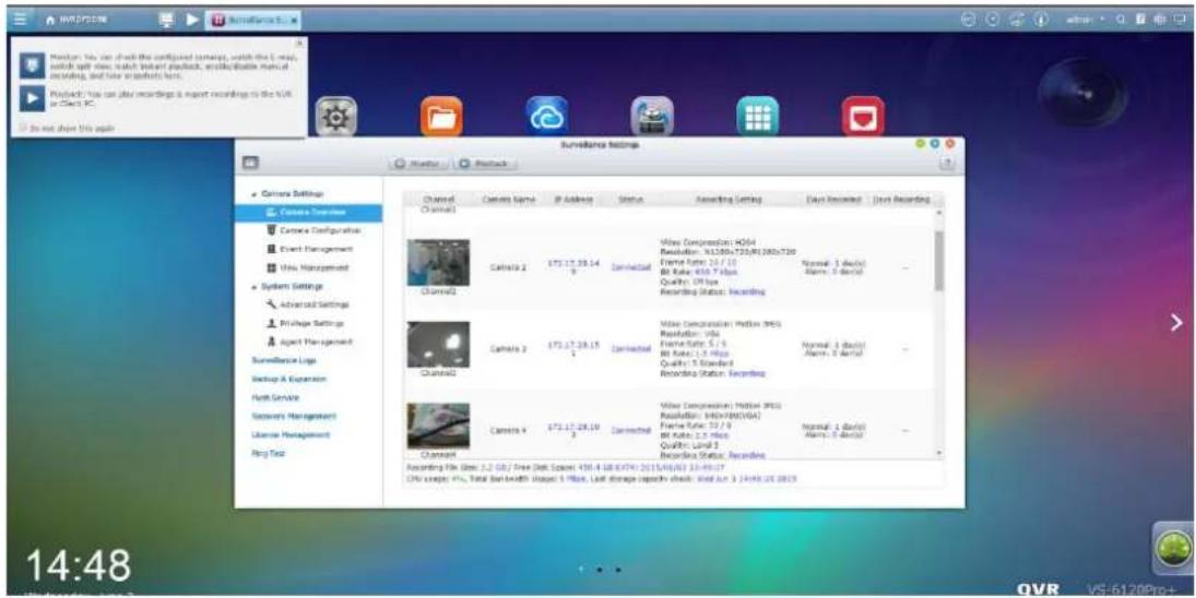
Please note: The system will enable Qstart once users nish the Qstart inializaon.
12.4 Qstart Mode
Main features:
- Intuitive channel mapping:
The video shown on channel 1 represents the recording view of port 1 to the switch.
● Auto port detecon and conguraon:
If devices are connected to other ports, the system will automatically detect the change and move all sengs (excluding advanced sengs) to the new ports. Users do not have to set it up all over again.
- Add a supported camera to the port:
If it is a new camera, the NVR will automatically add it using default sengs.
If it is a camera that has been used before, the NVR will use its previous sengs.
- Removing the camera from the port will clear the camera sengs.
- Any port changes will be saved in the system logs.
If you want to check Qstart mode, please go to [Surveillance Sengs] ->[Advanced Sengs]->[Qstart Sengs]. Also be sure to use supported switches to enable Qstart mode. The brand and model name will be shown and users can test the conncon.
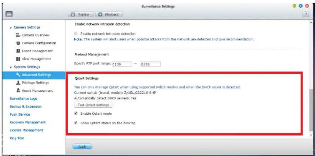
Qstart mode is enabled by default if users select Qstart during inializaon.
Otherwise it will be disabled. Users can also choose Manual Setup for inializaon if they are not planning to use Qstart. In Qstart mode, you cannot add cameras to specic channels. To get around this limitaon, you must disable Qstart in Advanced Sengs.
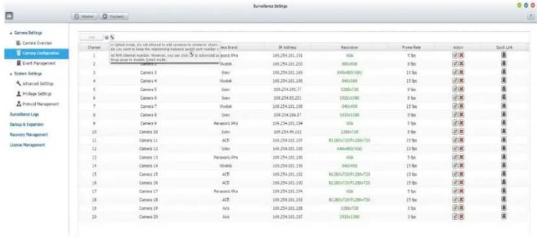
Please note:
If you enable Qstart mode again, all of your camera sengs will be erased.
Qstart desktop icon
- Provides users with Qstart on/off status on the VioStor desktop.
- Qstart is enabled:

Qstart is disabled:

Users can decide whether to show the icon or not.
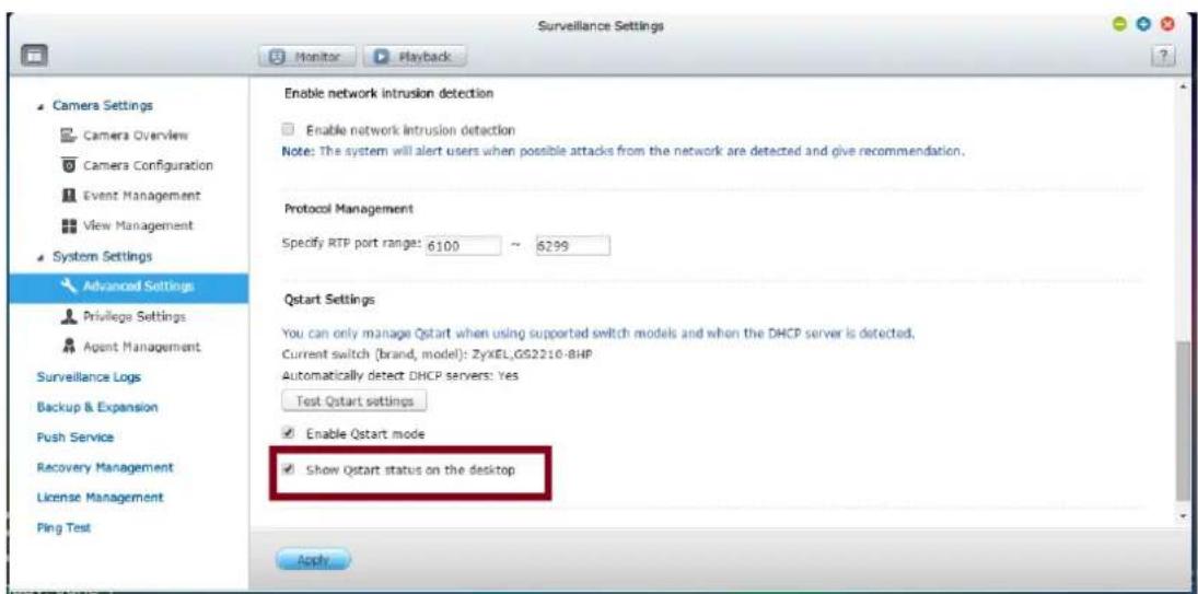
• Qstart Nocaons allow users to check Qstart on/off logs at the same me.
![Qstart Notifications Show All Warning (2) : [Switch] Qstart is enabled 2015-06-03 18:38:55 Warning : [Switch] Qstart is disabled 2015-06-03 18:38:47 Clear All](/content/2026/05/1128063/images/645a572d8cdc12f89b1a2a76139af6128093ada81f6c1f1ec4a7520af9171263.jpg)
Please note: VioStor will not only enable Qstart mode but also show the Qstart desktop icon once users nish inializing Qstart.
12.5 Network Switch Control (Embedded)
12.5.1 Topology:
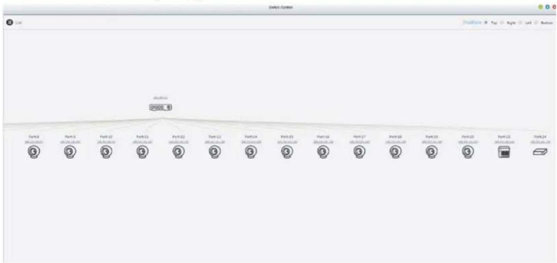
flowchart
graph TD
    A["Port0"] --> B["Port1"]
    B --> C["Port2"]
    C --> D["Port3"]
    D --> E["Port4"]
    E --> F["Port5"]
    F --> G["Port6"]
    G --> H["Port7"]
    H --> I["Port8"]
    I --> J["Port9"]
    J --> K["Port10"]
    K --> L["Port11"]
    L --> M["Port12"]
    M --> N["Port13"]
    N --> O["Port14"]
    O --> P["Port15"]
    P --> Q["Port16"]
    Q --> R["Port17"]
    R --> S["Port18"]
    S --> T["Port19"]
    T --> U["Port20"]
    U --> V["Port21"]
    V --> W["Port22"]
    W --> X["Port23"]
- Show the switch's complete conncon relationship
-
The diagram will display supported switches, cameras, VioStor NVR, and other devices (including PCs, laptops, unsupported switches, and other unknown devices.)
-
Users can choose dierent ways to display the topology (top/right/le/boom).
- Clicking the device's IP address will open that IP address in your browser.
- Clicking on a camera will open the camera's sengs page.
12.5.2 Switch Control Chart:
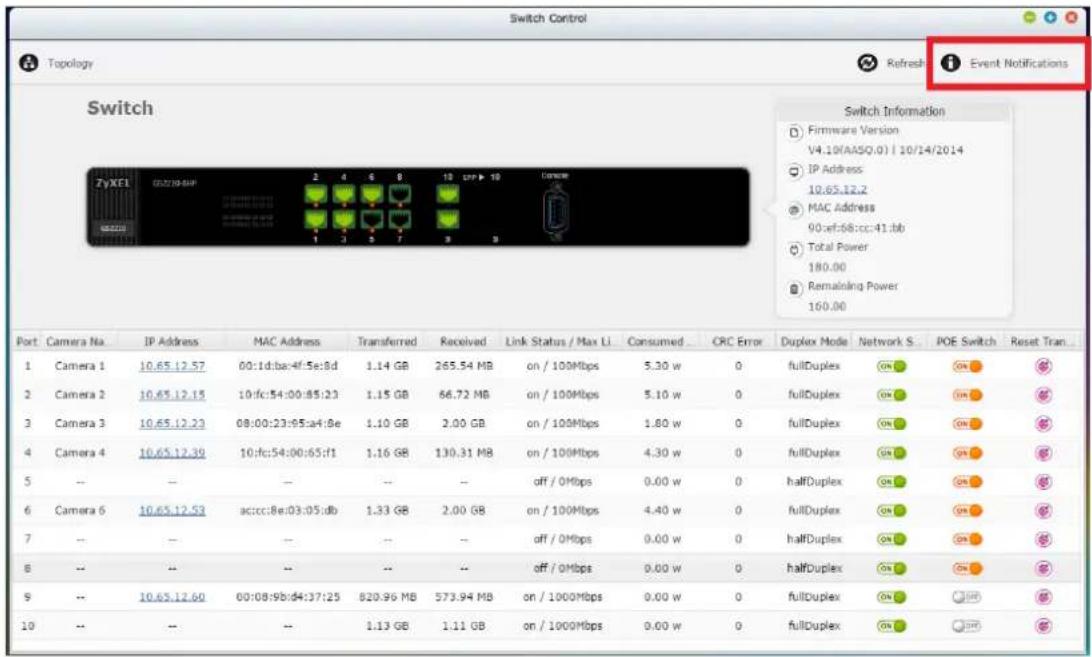
This switch control chart includes informaon as follows:
- Complete switch informaon table:
Firmware version, IP address, MAC, total power, and remaining power.
- Complete port informaon:
Camera name, Device IP, MAC, TX/RX, power consumpon, PoE ability, Network ability.
- Corresponding switch status types: 6 status types, combinaons of Network, PoE and link status. (N: Network, P: PoE, L: Link, Only N is on, then L can be detected as on/o.)
| gure | N | P | L |
| Off | Off | Off | |
 | Off | On | Off |
 | On | O | Off |
 | On | On | Off |
 | On | Off | On |
 | On | On | On |
12.5.3 Event Notifications:
- Enter the log list by selecng Event Nocations in Switch Control.
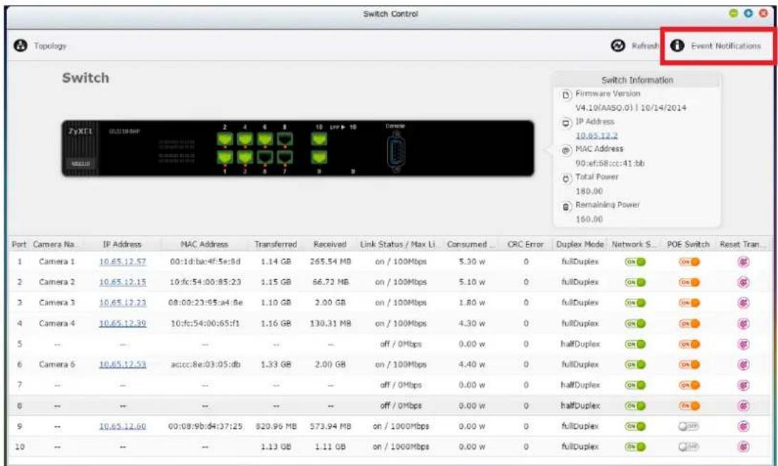
This table shows behaviors relevant to the switch only. Users can keep track of the situation between the switch and the devices linked to it.
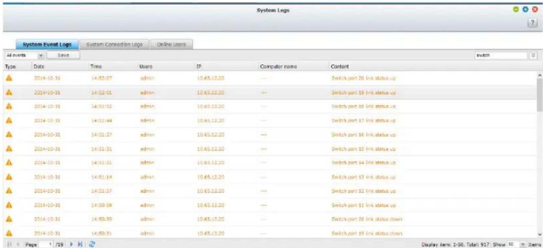
13.1.1 Compatibility List:
| Brand | Model | |
| NVR | QNAP | VS-6120 Pro+/ 6116 Pro+/ 6112 Pro+VS-4116 Pro+/ 4112 Pro+/ 4108 Pro+VS-2112 Pro+/ 2108 Pro+/ 2104 Pro+ |
| Switch | ZyXEL | GS2210-24HPGS2210-8HP |
| EtherWAN | EX76402EX22402 | |
| eten | PSG-6010VMPSG-6018VMPSG-7026VM | |
| IP Camera | AXIS、ACTi、SONY、Panasonic、VIVOTEK | |
Please note: The performance of Qstart will vary across dierent switch brands. If you have any quesons, please contact our technical support for more informaon.
14. LCD Panel
* This secon is applicable to the NVR models with an LCD panel only.
The NVR provides a handy LCD panel for users to perform the disk conguraon and view the system informaon.
When the NVR has started up, the server name and the IP address will be shown:
| N | V | R | 5 | F | 4 | D | E | 3 | |||||||
| 1 | 6 | 9 | . | 2 | 5 | 4 | . | 1 | 0 | 0 | . | 1 | 0 | 0 |
For the rst me installaon, the LCD panel shows the number of the hard disk drives detected and the IP address. Congure the hard drives accordingly.
| Number of hard drives detected | Default disk conguraon | Available disk conguraon opons* |
| 1 | Single | Single |
| 2 | RAID 1 | Single -> JBOD ->RAID 0 -> RAID 1 |
| 3 | RAID 5 | Single -> JBOD -> RAID 0 -> RAID 5 |
| 4 or above | RAID 5 | Single ->JBOD -> RAID 0 -> RAID 5-> RAID 6 |
*Press the 'Select' buon to choose the opon, and press the 'Enter' buon to conrm.
For example, when ve hard drives have been installed, the LCD panel shows:
| C | o | n | f | i | g | . | D | i | s | k | s | ? | |||
| → | R | A | I | D | 5 |
Press the 'Select' buon to browse more opons, e.g. RAID 6.
Press the 'Enter' buon and the following message shows. Press the 'Select' buon to select 'Yes' to conrm.
| C | h | o | o | s | e | R | A | I | D | 5 | ? | ||||
| → | Y | e | s | N | o |
When the conguraon has nished, the server name and the IP address will be shown. If the NVR fails to create the disk volume, the following message will be shown.
| C | r | e | a | t | i | n | g | . | . | . | |||||
| R | A | I | D | 5 | F | a | i | l | e | d |
View the system informaon by the LCD panel
When the LCD panel shows the server name and the IP address, press the 'Enter' buon to enter the Main Menu. The Main Menu consists of the following items:
- TCP/IP
- Physical disk
- Volume
- System
- Shut down
- Reboot
- Password
- Back
1. TCP/IP
In TCP/IP, the following opons are available:
1.1 LAN IP Address
1.2 LAN Subnet Mask
1.3 LAN Gateway
1.4 LAN PRI. DNS
1.5 LAN SEC. DNS
1.6 Enter Network Sengs
1.6.1 Network Sengs - DHCP
1.6.2 Network Sengs – Stac IP*
1.6.3 Network Sengs – BACK
1.7 Back to Main Menu
* In ‘Network Sengs – Stac IP’, congregate the IP address, subnet mask, gateway, and the DNS of LAN 1 and LAN 2.
2. Physical disk
In Physical disk, the following opons are available:
2.1 Disk Info
2.2 Back to Main Menu
The disk info shows the temperature and the capacity of the hard disk drive.
| D | i | s | k | : | 1 | T | e | m | p | : | 5 | 0 | ° | C | |
| S | i | z | e | : | 2 | 3 | 2 | G | B |
3. Volume
This secon shows the disk conguraon of the NVR. The rst line shows the RAID conguraon and storage capacity; the second line shows the member drive number of the conguraon.
| R | A | I | D | 5 | 7 | 5 | 0 | G | B | ||||||
| D | r | i | v | e | 1 | 2 | 3 | 4 |
If there is more than one volume, press the 'Select' buon to view the informaon. The following table shows the descripon of the LCD messages for the RAID 5 conguraon.
| LCD Display | Drive conguraon |
| RAID5+S | RAID5+spare |
| RAID5 (D) | RAID 5 degraded mode |
| RAID 5 (B) | RAID 5 rebuilding |
| RAID 5 (S) | RAID 5 re-synchronizing |
| RAID 5 (U) | RAID 5 is not mounted |
| RAID 5 (X) | RAID 5 non-acvated |
4. System
This secon shows the system temperature and the rotaon speed of the system fan.
| C | P | U | T | e | m | p | : | 5 | 0 | ° | C | ||||
| S | y | s | T | e | m | p | : | 5 | 5 | ° | C | ||||
| S | y | s | F | a | n | : | 8 | 6 | 5 | R | P | M | |||
5. Shut down
Use this opon to turn o the NVR. Press the 'Select' buon to select 'Yes'. Then press the 'Enter' buon to conrm.
6. Reboot
Use this opon to restart the NVR. Press the 'Select' buon to select 'Yes'. Then press the 'Enter' buon to conrm.
7. Password
The default password of the LCD panel is blank. Enter this opon to change the password of the LCD panel. Select 'Yes' to connue.
| C | h | a | n | g | e | P | a | s | s | w | o | r | d | ||
| Y | e | s | → | N | o |
Enter a password of maximum 8 numeric characters (0-9). When the cursor moves to 'OK', press the 'Enter' buon. Verify the password to conrm the changes.
| N | e | w | P | a | s | s | w | o | r | d | : | ||||
| O | K |
8. Back
Select this opon to return to the main menu.
System Messages
When the NVR encounters system error, an error message will be shown on the LCD panel. Press the 'Enter' buon to view the message. Press the 'Enter' buon again to view the next message.
| S | y | s | t | e | m | E | r | r | o | r | ! | ||||
| P | l | s | . | C | h | e | c | k | L | o | g | s |
| System Message | Descripon |
| Sys. Fan Failed | The system fan fails |
| Sys. Overheat | The system overheats |
| HDD Overheat | The hard drive overheats |
| CPU Overheat | The CPU overheats |
| Network Lost | Both LAN 1 and LAN 2 are disconnected in failover or load-balancing mode |
| LAN1 Lost | LAN 1 is disconnected |
| LAN2 Lost | LAN 2 is disconnected |
| HDD Failure | The hard drive fails |
| Vol1 Full | The volume is full |
| HDD Ejected | The hard drive is ejected |
| Vol1 Degraded | The volume is in degraded mode |
| Vol1 Unmounted | The volume is not mounted |
| Vol1 Nonacvate | The volume is not acvated |
15. Troubleshooting
1. The monitoring screen did not display.
Please check the following:
a. Check if the AcveX add-on has been installed when logging in the monitoring page of the NVR. Set the security level to 'Medium' or lower in Internet Opons of the IE browser.
b. The NVR is turned on and the network is correctly connected.
c. The IP address of the NVR does not conict with other devices in the same subnet.
d. Check the IP address settings of the NVR and the computer. Make sure they are on the same subnet.
2. A channel on the monitoring page cannot be displayed.
Please check the following:
a. The IP address, the name, and the password entered on the camera conguraon page are correct. Use the 'Test' funcon to verify the conncon.
b. When the PC and the IP camera are on the same subnet, while the NVR is on another subnet, the monitoring screen cannot be viewed from the PC. Solve the problems by the following methods.
Method 1: Enter the IP address of the IP camera as the WAN IP on the NVR.
Method 2: Congure the router to allow internal access to the public IP address and the mapped ports of the IP cameras.
3. The recording is not working properly.
a. Install the hard drive(s) correctly in the NVR.
b. Make sure each hard disk tray is correctly locked.
c. Check if the recording funcon is enabled on the Camera Conguraon page (the funcon is enabled by default). Make sure the IP address, the login name, and the password of the IP camera are correct.
d. If the above items are verified to work properly while the status LED ashes green, the hard drive may be damaged or cannot be detected. In this case, turn o the NVR and install a new hard disk. If the problem persists, please
contact the technical support.
Note: When the conguraons of the NVR are being updated, the recording will be stopped temporarily and restart again shortly.
4. I cannot login the administraon page of the NVR.
Please check if you have the administrator authority. Only administrators are allowed to login the NVR.
5. The live video is not clear or smooth somemes.
a. The image quality may be restricted and interfered by the network trac.
b. When there are mulple conncons to the IP camera or the NVR, the image quality will be reduced. It is recommended to allow only three simultaneous conncons to the monitoring page at maximum. For higher recording performance, do not open too many IE browsers to view the live video.
c. The same IP camera may be shared by mulple NVR servers for recording at the same me.
6. The alarm recording does not funcon.
a. Please login the NVR and go to 'Camera Setngs' > 'Alarm Sengs'. Make sure the alarm recording is enabled for the IP camera.
b. If the NVR is installed behind a router while the IP camera is not, the alarm recording will not work.
c. When the alarm recording is enabled, make sure the number of days that the alarm recordings will be retained have been specied in 'Camera Sengs' > 'Advanced Setngs'. Otherwise, the recordings may be overwrien.
7. The estimated storage space for recording displayed on the 'Recording Sengs' page is dierent from the actual value.
This esmated value is a reference value only. The actual disk space may vary according to the image contents, the network environment, and the performance of the IP cameras.
8. The E-map cannot be displayed correctly.
Please check the le format. The NVR supports E-map in JPEG only.
9. I cannot nd the NVR by the QNAP Finder.
a. Check if the NVR has been turned on.
b. Connect the local PC and the NVR to the same subnet.
c. Install the latest version of Finder from www.qnapsecurity.com.
d. Run Finder again to search for the NVR. Make sure all the rewall software on the computer have been turned o; or add the Finder to the list of allowed programs in the rewall.
e. If the NVR is not found, click 'Refresh' on the Finder to try again.
f. If the problem persists, contact the technical support.
10. The changes to the system configuraon did not take eect.
Aer changing the sengs on the administration page, click 'Apply' to apply the changes.
11. The monitoring page cannot be fully displayed in Internet Explorer.
When using the zooming funcon of Internet Explorer, the page may not be displayed properly. Please click F5 to refresh the page.
12. I cannot use the SMB, FTP, and Web File Manager services of the NVR.
a. Login the NVR as an administrator. Go to 'Network Sengs' > 'File Services' and check if these three funcons are enabled.
b. If the NVR is installed behind a router, the SMB and FTP services can only be accessed from the same subnet. Please refer to Appendix B for details.
13. The NVR takes too long to restart.
When the NVR takes more than 5 minutes to restart, turn o the power and turn on the server again. If the problem persists, please contact the technical support.
Appendix A Configuration Examples
Environment 1: The NVR, the IP camera, and the monitoring PC are all on the same network
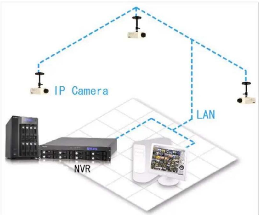
flowchart
graph TD
    A["IP Camera"] --> B["NVR"]
    B --> C["LAN"]
    C --> D["Server"]
    style A fill:#f9f,stroke:#333
    style B fill:#ccf,stroke:#333
    style C fill:#cfc,stroke:#333
    style D fill:#fcc,stroke:#333
| IP address | |
| NVR | 192.168.1.1 |
| PC | 192.168.1.100 |
| Camera 1 | 192.168.1.101 |
| Camera 2 | 192.168.1.102 |
| Camera 3 | 192.168.1.103 |
In the example, add the IP cameras to the NVR by entering the IP addresses of the IP cameras.
Environment 2: The NVR and the IP camera are installed behind the router, while the monitoring PC is located remotely
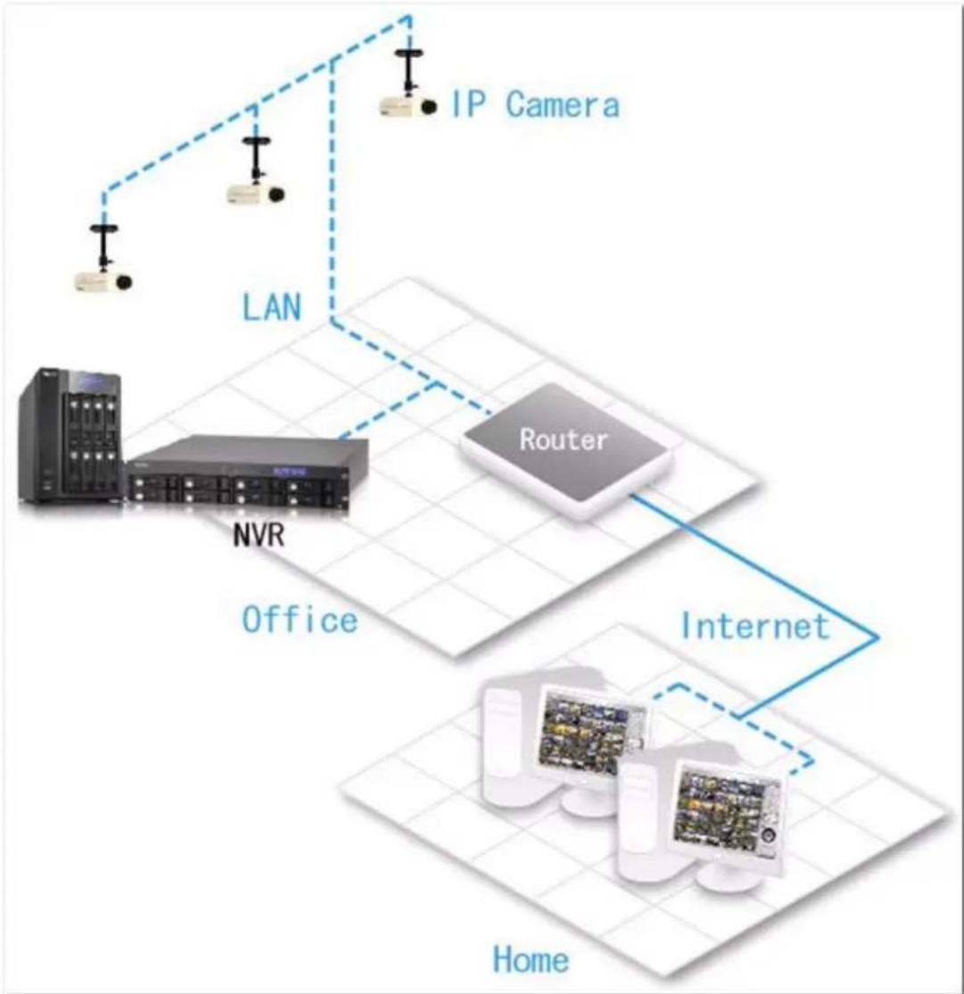
flowchart
graph TD
    A["IP Camera"] --> B["LAN"]
    B --> C["NVR Server"]
    C --> D["Office"]
    D --> E["Router"]
    E --> F["Internet"]
    F --> G["Home"]
    style A fill:#f9f,stroke:#333
    style B fill:#ccf,stroke:#333
    style C fill:#cfc,stroke:#333
    style D fill:#fcc,stroke:#333
    style E fill:#cff,stroke:#333
    style F fill:#ffc,stroke:#333
    style G fill:#cfc,stroke:#333
| IP address | Mapped port on the router | |
| NVR | 192.168.1.1 | 8000 |
| Camera 1 | 192.168.1.101 | 8001 |
| Camera 2 | 192.168.1.102 | 8002 |
| Camera 3 | 192.168.1.103 | 8003 |
| Router public IP | 219.87.144.205 | |
| PC | 10.8.10.100 |
To allow a remote PC to connect to the NVR and the IP cameras, do the following:
Step 1. Set up the port mapping (virtual server) on the router.
| From | Forward to |
| 219.87.144.205:8000 | 192.168.1.1:80 |
| 219.87.144.205:8001 | 192.168.1.101:80 |
| 219.87.144.205:8002 | 192.168.1.102:80 |
| 219.87.144.205:8003 | 192.168.1.103:80 |
Step 2. Add the IP camera to the NVR by entering the IP address of the IP camera in the 'IP Address' sengs. Enter the public IP address of the router and the mapped ports of the IP camera in the 'WAN IP Address' sengs.
Note: When conguring the IP camera, the WAN IP and LAN IP must be entered.
To open FTP (port 21) and SMB (port 445) of the NVR on WAN, congregate the following port mapping sengs:
| From | Forward to |
| 219.87.144.205:21 | 192.168.1.1:21 |
| 219.87.144.205:139 | 192.168.1.1:139 |
| 219.87.144.205:445 | 192.168.1.1:445 |
Aer nishing the above two steps, connect to the NVR on WAN by entering the IP address hp://219.87.144.205:8000 in the IE browser. Then login the NVR with the correct user name and password.
If the port specified to the NVR is 80, enter hp://219.87.144.205 to connect to the NVR.
Note: If the router does not use a xed IP, congure the DDNS sengs on the router. Other conguraons are the same as above.
Environment 3: The NVR and the IP camera are all located remotely
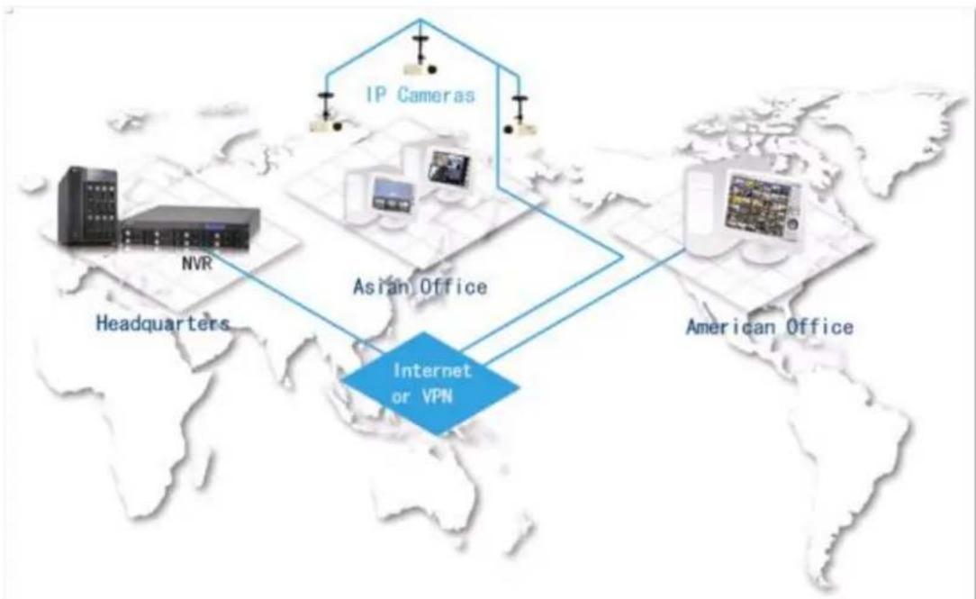
flowchart
graph TD
    A["NVR"] --> B["Headquarters"]
    C["IP Cameras"] --> D["Asian Office"]
    E["American Office"] --> F["Internet or VPN"]
    B --> D
    D --> F
| IP address | |
| NVR | 219.87.144.205 |
| Camera 1 | 61.62.100.101 |
| Camera 2 | 61.62.100.102 |
| Camera 3 | 61.62.100.103 |
In this example, add the IP camera to the NVR by adding its IP address to the 'IP Address' sengs.
Note: If a parcular port is assigned to connect to the IP camera, specify the port in the system conguraon.
Environment 4: The NVR and the IP camera are installed behind the router
| IP address | |
| NVR 1 | 192.168.1.101 |
| NVR 2 | 192.168.1.102 |
| NVR 3 | 192.168.1.103 |
| Router public IP | 219.87.145.205 |
In the example, to allow a remote PC to connect to each NVR by FTP, do the following:
Step 1. Set up the port mapping (virtual server) on the router
| From | Forward to | |
| NVR 1 | 219.87.145.205:2001 | 192.168.1.101:21 |
| NVR 2 | 219.87.145.205:2002 | 192.168.1.102:21 |
| NVR 3 | 219.87.145.205:2003 | 192.168.1.103:21 |
Connect to NVR 1 by p://219.87.145.205:2001
Connect to NVR 2 by p://219.87.145.205:2002
Connect to NVR 3 by p://219.87.145.205:2003
Step 2. Enable FTP port mapping on the NVR
To connect to each NVR via FTP by clicking 'FTP' on the playback page of each NVR, enable FTP port mapping in 'Network Sengs' > 'File Services' on the system administraon page and set the mapped port number.
| Mapped port | |
| NVR 1 | 2001 |
| NVR 2 | 2002 |
| NVR 3 | 2003 |
Aer nishing the above two steps, connect to the NVR via FTP by entering the IP address in the IE browser or clicking 'FTP' on the playback page. Then login the NVR by the correct user name and password.
Technical Support
QNAP provides dedicated online support and customer service via instant messenger.
Online Support: hp://www.qnapsecurity.com/onlinesupport.asp
Facebook: hps://www.facebook.com/nvr.qnap
Forum: hp://forum.qnapsecurity.com
Technical Support in the USA and Canada:
Email: q_supportus@qnap.com
TEL: +1-909-595-2782
Address: 168 University Parkway, Pomona CA 91768
Service Hours: 08:00-17:00 (GMT- 08:00 Pacic Time, Monday to Friday)
GNU GENERAL PUBLIC LICENSE
Version 3, 29 June 2007
Copyright © 2007 Free Soware Foundaon, Inc.
Everyone is permied to copy and distribute verbam copies of this license document, but changing it is not allowed.
Preamble
The GNU General Public License is a free, copyle license for soware and other kinds of works.
The licenses for most soware and other praccal works are designed to take away your freedom to share and change the works. By contrast, the GNU General Public License is intended to guarantee your freedom to share and change all versions of a program--to make sure it remains free soware for all its users. We, the Free Soware Foundaon, use the GNU General Public License for most of our soware; it applies also to any other work released this way by its authors. You can apply it to your programs, too.
When we speak of free soware, we are referring to freedom, not price. Our General Public Licenses are designed to make sure that you have the freedom to distribute copies of free soware (and charge for them if you wish), that you receive source code or can get it if you want it, that you can change the soware or use pieces of it in new free programs, and that you know you can do these things.
To protect your rights, we need to prevent others from denying you these rights or asking you to surrender the rights. Therefore, you have certain responsibilities if you distribute copies of the soware, or if you modify it: responsibilities to respect the freedom of others.
For example, if you distribute copies of such a program, whether gras or for a fee, you must pass on to the recipients the same freedoms that you received. You must make sure that they, too, receive or can get the source code. And you must show
them these terms so they know their rights.
Developers that use the GNU GPL protect your rights with two steps: (1) assert copyright on the soware, and (2) oer you this License giving you legal permission to copy, distribute and/or modify it.
For the developers' and authors' protecon, the GPL clearly explains that there is no warranty for this free soware. For both users' and authors' sake, the GPL requires that modified versions be marked as changed, so that their problems will not be aributed erroneously to authors of previous versions.
Some devices are designed to deny users access to install or run modified versions of the soware inside them, although the manufacturer can do so. This is fundamentally incompatible with the aim of protecng users' freedom to change the soware. The systemac paern of such abuse occurs in the area of products for individuals to use, which is precisely where it is most unacceptable. Therefore, we have designed this version of the GPL to prohibit the pracce for those products. If such problems arise substantially in other domains, we stand ready to extend this provision to those domains in future versions of the GPL, as needed to protect the freedom of users.
Finally, every program is threatened constantly by soware patents. States should not allow patents to restrict development and use of soware on general-purpose computers, but in those that do, we wish to avoid the special danger that patents applied to a free program could make it eecvely proprietary. To prevent this, the GPL assures that patents cannot be used to render the program non-free.
The precise terms and conditions for copying, distribuon and modicaon follow.
TERMS AND CONDITIONS
0. Denions.
'This License' refers to version 3 of the GNU General Public License.
'Copyright' also means copyright-like laws that apply to other kinds of works, such as semiconductor masks.
'The Program' refers to any copyrightable work licensed under this License. Each licensee is addressed as 'you'. 'Licensees' and 'recipients' may be individuals or
organizaons.
To ‘modify’ a work means to copy from or adapt all or part of the work in a fashion requiring copyright permission, other than the making of an exact copy. The resulting work is called a ‘modified version’ of the earlier work or a work ‘based on’ the earlier work.
A ‘covered work’ means either the unmodified Program or a work based on the Program.
To ‘propagate’ a work means to do anything with it that, without permission, would make you directly or secondarily liable for infringement under applicable copyright law, except execung it on a computer or modifying a private copy. Propagaon includes copying, distribuon (with or without modicaon), making available to the public, and in some countries other advies as well.
To ‘convey’ a work means any kind of propagaon that enables other pares to make or receive copies. Mere interacon with a user through a computer network, with no transfer of a copy, is not conveying.
An interactive user interface displays ‘Appropriate Legal Noces’ to the extent that it includes a convenient and prominently visible feature that (1) displays an appropriate copyright noce, and (2) tells the user that there is no warranty for the work (except to the extent that warranes are provided), that licensees may convey the work under this License, and how to view a copy of this License. If the interface presents a list of user commands or opons, such as a menu, a prominent item in the list meets this criterion.
1. Source Code.
The ‘source code’ for a work means the preferred form of the work for making modicaons to it. ‘Object code’ means any non-source form of a work.
A ‘Standard Interface’ means an interface that either is an ofcial standard dened by a recognized standards body, or, in the case of interfaces specified for a particular programming language, one that is widely used among developers working in that language.
The ‘System Libraries’ of an executable work include anything, other than the work
as a whole, that (a) is included in the normal form of packaging a Major Component, but which is not part of that Major Component, and (b) serves only to enable use of the work with that Major Component, or to implement a Standard Interface for which an implementation is available to the public in source code form. A 'Major Component', in this context, means a major essential component (kernel, window system, and so on) of the specific operating system (if any) on which the executable work runs, or a compiler used to produce the work, or an object code interpreter used to run it.
The ‘Corresponding Source’ for a work in object code form means all the source code needed to generate, install, and (for an executable work) run the object code and to modify the work, including scripts to control those advies. However, it does not include the work's System Libraries, or general-purpose tools or generally available free programs which are used unmodified in performing those advies but which are not part of the work. For example, Corresponding Source includes interface denion les associated with source les for the work, and the source code for shared libraries and dynamically linked subprograms that the work is specifically designed to require, such as by inmate data communicaon or control ow between those subprograms and other parts of the work.
The Corresponding Source need not include anything that users can regenerate automacally from other parts of the Corresponding Source.
The Corresponding Source for a work in source code form is that same work.
2. Basic Permissions.
All rights granted under this License are granted for the term of copyright on the Program, and are irrevocable provided the stated conditions are met. This License explicitly arms your unlimited permission to run the unmodified Program. The output from running a covered work is covered by this License only if the output, given its content, constutes a covered work. This License acknowledges your rights of fair use or other equivalent, as provided by copyright law.
You may make, run and propagate covered works that you do not convey, without condions so long as your license otherwise remains in force. You may convey covered works to others for the sole purpose of having them make modicaons exclusively for you, or provide you with facilities for running those works, provided that you comply with the terms of this License in conveying all material for which you
do not control copyright. Those thus making or running the covered works for you must do so exclusively on your behalf, under your direcon and control, on terms that prohibit them from making any copies of your copyrighted material outside their relationship with you.
Conveying under any other circumstances is permied solely under the conditions stated below. Sublicensing is not allowed; secon 10 makes it unnecessary.
3. Protecng Users' Legal Rights From An-Circumvenon Law.
No covered work shall be deemed part of an eecve technological measure under any applicable law fulfilling obligaons under arcle 11 of the WIPO copyright treaty adopted on 20 December 1996, or similar laws prohibiting or restrictive circumvenon of such measures.
When you convey a covered work, you waive any legal power to forbid circumvenon of technological measures to the extent such circumvenon is elected by exercising rights under this License with respect to the covered work, and you disclaim any intenon to limit operaon or modicaon of the work as a means of enforcing, against the work's users, your or third pares' legal rights to forbid circumvenon of technological measures.
4. Conveying Verbam Copies.
You may convey verbam copies of the Program's source code as you receive it, in any medium, provided that you conspicuously and appropriately publish on each copy an appropriate copyright noce; keep intact all noces stang that this License and any non-permissive terms added in accord with secon 7 apply to the code; keep intact all noces of the absence of any warranty; and give all recipients a copy of this License along with the Program.
You may charge any price or no price for each copy that you convey, and you may oer support or warranty protecon for a fee.
5. Conveying Modied Source Versions.
You may convey a work based on the Program, or the modicaons to produce it from the Program, in the form of source code under the terms of secon 4, provided that you also meet all of these conditions:
a) The work must carry prominent noces stang that you modified it, and giving a
relevant date.
b) The work must carry prominent noces stang that it is released under this License and any condions added under secon 7. This requirement modifies the requirement in secon 4 to 'keep intact all notices'.
c) You must license the enre work, as a whole, under this License to anyone who comes into possession of a copy. This License will therefore apply, along with any applicable secon 7 additional terms, to the whole of the work, and all its parts, regardless of how they are packaged. This License gives no permission to license the work in any other way, but it does not invalidate such permission if you have separately received it.
d) If the work has interact user interfaces, each must display Appropriate Legal Noces; however, if the Program has interact interfaces that do not display Appropriate Legal Noces, your work need not make them do so.
A compilaon of a covered work with other separate and independent works, which are not by their nature extensions of the covered work, and which are not combined with it such as to form a larger program, in or on a volume of a storage or distribuon medium, is called an ‘aggregate’ if the compilaon and its resulting copyright are not used to limit the access or legal rights of the compilaon's users beyond what the individual works permit. Inclusion of a covered work in an aggregate does not cause this License to apply to the other parts of the aggregate.
- Conveying Non-Source Forms.
You may convey a covered work in object code form under the terms of seconds 4 and 5, provided that you also convey the machine-readable Corresponding Source under the terms of this License, in one of these ways:
a) Convey the object code in, or embodied in, a physical product (including a physical distribuon medium), accompanied by the Corresponding Source xed on a durable physical medium customarily used for soware interchange.
b) Convey the object code in, or embodied in, a physical product (including a physical distribuon medium), accompanied by a wrien oer, valid for at least three years and valid for as long as you oer spare parts or customer support for that product model, to give anyone who possesses the object code either (1) a copy of the Corresponding Source for all the soware in the product that is covered by this License, on a durable physical medium customarily used for soware interchange, for a price no more than your reasonable cost of physically performing this conveying of source, or (2) access to copy the Corresponding Source from a network server at no charge.
c) Convey individual copies of the object code with a copy of the written order to provide the Corresponding Source. This alternate is allowed only occasionally and noncommercially, and only if you received the object code with such an order, in accord with subsecond 6b.
d) Convey the object code by oering access from a designated place (gras or for a charge), and oer equivalent access to the Corresponding Source in the same way through the same place at no further charge. You need not require recipients to copy the Corresponding Source along with the object code. If the place to copy the object code is a network server, the Corresponding Source may be on a dierent server (operated by you or a third party) that supports equivalent copying facilities, provided you maintain clear direcons next to the object code saying where to nd the Corresponding Source. Regardless of what server hosts the Corresponding Source, you remain obligated to ensure that it is available for as long as needed to sasfy these requirements.
e) Convey the object code using peer-to-peer transmission, provided you inform other peers where the object code and Corresponding Source of the work are being oered to the general public at no charge under subsecon 6d.
A separable poron of the object code, whose source code is excluded from the Corresponding Source as a System Library, need not be included in conveying the object code work.
A ‘User Product’ is either (1) a ‘consumer product’, which means any tangible personal property which is normally used for personal, family, or household purposes, or (2) anything designed or sold for incorporaon into a dwelling. In determining whether a product is a consumer product, doubul cases shall be resolved in favor of coverage. For a parcular product received by a parcular user, ‘normally used’ refers to a typical or common use of that class of product, regardless of the status of the parcular user or of the way in which the parcular user actually uses, or expects or is expected to use, the product. A product is a consumer product regardless of whether the product has substantial commercial, industrial or non-consumer uses, unless such uses represent the only significant mode of use of the product.
'Installaon Informaon' for a User Product means any methods, procedures, authorizaon keys, or other informaon required to install and execute modified versions of a covered work in that User Product from a modified version of its Corresponding Source. The informaon must suce to ensure that the connued funconing of the modified object code is in no case prevented or interfered with solely because modicaon has been made.
If you convey an object code work under this secon in, or with, or specifically for use in, a User Product, and the conveying occurs as part of a transacon in which the right of possession and use of the User Product is transferred to the recipient in perpetuity or for a xed term (regardless of how the transacon is characterized), the Corresponding Source conveyed under this secon must be accompanied by the Installaon Informaon. But this requirement does not apply if neither you nor any third party retains the ability to install modified object code on the User Product (for example, the work has been installed in ROM).
The requirement to provide Installaon Informaon does not include a requirement to connue to provide support service, warranty, or updates for a work that has been modified or installed by the recipient, or for the User Product in which it has been modified or installed. Access to a network may be denied when the modicaon itself materially and adversely aects the operaon of the network or violates the rules and protocols for communicaon across the network.
Corresponding Source conveyed, and Installaon Informaon provided, in accord with this secon must be in a format that is publicly documented (and with an implementaon available to the public in source code form), and must require no special password or key for unpacking, reading or copying.
7. Additional Terms.
'Additional permissions' are terms that supplement the terms of this License by making exceptions from one or more of its conditions. Additional permissions that are applicable to the enre Program shall be treated as though they were included in this License, to the extent that they are valid under applicable law. If additional permissions apply only to part of the Program, that part may be used separately under those permissions, but the enre Program remains governed by this License without regard to the additional permissions.
When you convey a copy of a covered work, you may at your opon remove any additional permissions from that copy, or from any part of it. (Additional permissions may be written to require their own removal in certain cases when you modify the work.) You may place additional permissions on material, added by you to a covered work, for which you have or can give appropriate copyright permission.
Notwithstanding any other provision of this License, for material you add to a
covered work, you may (if authorized by the copyright holders of that material) supplement the terms of this License with terms:
a) Disclaiming warranty or liming liability dierently from the terms of seconds 15 and 16 of this License; or
b) Requiring preservaon of specied reasonable legal noces or author aribuons in that material or in the Appropriate Legal Noces displayed by works containing it; or
c) Prohibing misrepresentaon of the origin of that material, or requiring that modified versions of such material be marked in reasonable ways as dierent from the original version; or
d) Liming the use for publicity purposes of names of licensors or authors of the material; or
e) Declining to grant rights under trademark law for use of some trade names, trademarks, or service marks; or
f) Requiring indemnicaon of licensors and authors of that material by anyone who conveys the material (or modified versions of it) with contractual assumptions of liability to the recipient, for any liability that these contractual assumptions directly impose on those licensors and authors.
All other non-permissive additional terms are considered ‘further restricons’ within the meaning of secon 10. If the Program as you received it, or any part of it, contains a noce stang that it is governed by this License along with a term that is a further restricon, you may remove that term. If a license document contains a further restricon but permits relicensing or conveying under this License, you may add to a covered work material governed by the terms of that license document, provided that the further restricon does not survive such relicensing or conveying.
If you add terms to a covered work in accord with this secon, you must place, in the relevant source les, a statement of the additional terms that apply to those les, or a noce indicang where to nd the applicable terms.
Additional terms, permissive or non-permissive, may be stated in the form of a separately written license, or stated as excepons; the above requirements apply either way.
8. Terminaon.
You may not propagate or modify a covered work except as expressly provided under this License. Any aempt otherwise to propagate or modify it is void, and will
automacally terminate your rights under this License (including any patent licenses granted under the third paragraph of secon 11).
However, if you cease all violaon of this License, then your license from a parcular copyright holder is reinstated (a) provisionally, unless and unl the copyright holder explicitly and nally terminates your license, and (b) permanently, if the copyright holder fails to nofy you of the violaon by some reasonable means prior to 60 days aer the cessaon.
Moreover, your license from a parcular copyright holder is reinstated permanently if the copyright holder noes you of the violaon by some reasonable means, this is the rst me you have received noce of violaon of this License (for any work) from that copyright holder, and you cure the violaon prior to 30 days aer your receipt of the noce.
Terminaon of your rights under this secon does not terminate the licenses of pares who have received copies or rights from you under this License. If your rights have been terminated and not permanently reinstated, you do not qualify to receive new licenses for the same material under secon 10.
9. Acceptance Not Required for Having Copies.
You are not required to accept this License in order to receive or run a copy of the Program. Ancillary propagaon of a covered work occurring solely as a consequence of using peer-to-peer transmission to receive a copy likewise does not require acceptance. However, nothing other than this License grants you permission to propagate or modify any covered work. These acons infringe copyright if you do not accept this License. Therefore, by modifying or propagang a covered work, you indicate your acceptance of this License to do so.
10. Automac Licensing of Downstream Recipients.
Each me you convey a covered work, the recipient automacally receives a license from the original licensors, to run, modify and propagate that work, subject to this License. You are not responsible for enforcing compliance by third pares with this License.
An ‘enty transacon’ is a transacon transferring control of an organizaon, or substanally all assets of one, or subdividing an organizaon, or merging organizaons. If propagaon of a covered work results from an enty transacon,
each party to that transacon who receives a copy of the work also receives whatever licenses to the work the party's predecessor in interest had or could give under the previous paragraph, plus a right to possession of the Corresponding Source of the work from the predecessor in interest, if the predecessor has it or can get it with reasonable eorts.
You may not impose any further restricons on the exercise of the rights granted or armed under this License. For example, you may not impose a license fee, royalty, or other charge for exercise of rights granted under this License, and you may not initiate ligaon (including a cross-claim or counterclaim in a lawsuit) alleging that any patent claim is infringed by making, using, selling, oering for sale, or imporng the Program or any poron of it.
11. Patents.
A ‘contributor’ is a copyright holder who authorizes use under this License of the Program or a work on which the Program is based. The work thus licensed is called the contributor's ‘contributor version’.
A contributor's ‘essenal patent claims’ are all patent claims owned or controlled by the contributor, whether already acquired or hereaer acquired, that would be infringed by some manner, permied by this License, of making, using, or selling its contributor version, but do not include claims that would be infringed only as a consequence of further modicaon of the contributor version. For purposes of this denion, ‘control’ includes the right to grant patent sublicenses in a manner consistent with the requirements of this License.
Each contributor grants you a non-exclusive, worldwide, royalty-free patent license under the contributor's essenal patent claims, to make, use, sell, oer for sale, import and otherwise run, modify and propagate the contents of its contributor version.
In the following three paragraphs, a ‘patent license’ is any express agreement or commitment, however denominated, not to enforce a patent (such as an express permission to pracce a patent or covenant not to sue for patent infringement). To ‘grant’ such a patent license to a party means to make such an agreement or commitment not to enforce a patent against the party.
If you convey a covered work, knowingly relying on a patent license, and the
Corresponding Source of the work is not available for anyone to copy, free of charge and under the terms of this License, through a publicly available network server or other readily accessible means, then you must either (1) cause the Corresponding Source to be so available, or (2) arrange to deprive yourself of the benet of the patent license for this parcular work, or (3) arrange, in a manner consistent with the requirements of this License, to extend the patent license to downstream recipients. 'Knowingly relying' means you have actual knowledge that, but for the patent license, your conveying the covered work in a country, or your recipient's use of the covered work in a country, would infringe one or more idenable patents in that country that you have reason to believe are valid.
If, pursuant to or in conneccon with a single transacon or arrangement, you convey, or propagate by procuring conveyance of, a covered work, and grant a patent license to some of the pares receiving the covered work authorizing them to use, propagate, modify or convey a specic copy of the covered work, then the patent license you grant is automatically extended to all recipients of the covered work and works based on it.
A patent license is ‘discriminatory’ if it does not include within the scope of its coverage, prohibits the exercise of, or is condioned on the non-exercise of one or more of the rights that are specifically granted under this License. You may not convey a covered work if you are a party to an arrangement with a third party that is in the business of distribung soware, under which you make payment to the third party based on the extent of your acvity of conveying the work, and under which the third party grants, to any of the pares who would receive the covered work from you, a discriminatory patent license (a) in conncon with copies of the covered work conveyed by you (or copies made from those copies), or (b) primarily for and in conncon with speci products or compilaons that contain the covered work, unless you entered into that arrangement, or that patent license was granted, prior to 28 March 2007.
Nothing in this License shall be construed as excluding or liming any implied license or other defenses to infringement that may otherwise be available to you under applicable patent law.
12. No Surrender of Others' Freedom.
If condions are imposed on you (whether by court order, agreement or otherwise) that contradict the condions of this License, they do not excuse you from the
conditions of this License. If you cannot convey a covered work so as to sasfy simultaneously your obligaons under this License and any other pernent obligaons, then as a consequence you may not convey it at all. For example, if you agree to terms that obligate you to collect a royalty for further conveying from those to whom you convey the Program, the only way you could sasfy both those terms and this License would be to refrain enrely from conveying the Program.
13. Use with the GNU Aero General Public License.
Notwithstanding any other provision of this License, you have permission to link or combine any covered work with a work licensed under version 3 of the GNU Aero General Public License into a single combined work, and to convey the resulting work. The terms of this License will connue to apply to the part which is the covered work, but the special requirements of the GNU Aero General Public License, secon 13, concerning interacon through a network will apply to the combinaon as such.
14. Revised Versions of this License.
The Free Soware Foundaon may publish revised and/or new versions of the GNU General Public License from me to me. Such new versions will be similar in spirit to the present version, but may differ in detail to address new problems or concerns.
Each version is given a disguishing version number. If the Program species that a certain numbered version of the GNU General Public License ‘or any later version’ applies to it, you have the opon of following the terms and condions either of that numbered version or of any later version published by the Free Soware Foundaon. If the Program does not specify a version number of the GNU General Public License, you may choose any version ever published by the Free Soware Foundaon.
If the Program species that a proxy can decide which future versions of the GNU General Public License can be used, that proxy's public statement of acceptance of a version permanently authorizes you to choose that version for the Program.
Later license versions may give you additional or dierent permissions. However, no additional obligaons are imposed on any author or copyright holder as a result of your choosing to follow a later version.
15. Disclaimer of Warranty.
THERE IS NO WARRANTY FOR THE PROGRAM, TO THE EXTENT PERMITTED BY APPLICABLE LAW. EXCEPT WHEN OTHERWISE STATED IN WRITING THE COPYRIGHT
HOLDERS AND/OR OTHER PARTIES PROVIDE THE PROGRAM 'AS IS' WITHOUT WARRANTY OF ANY KIND, EITHER EXPRESSED OR IMPLIED, INCLUDING, BUT NOT LIMITED TO, THE IMPLIED WARRANTIES OF MERCHANTABILITY AND FITNESS FOR A PARTICULAR PURPOSE. THE ENTIRE RISK AS TO THE QUALITY AND PERFORMANCE OF THE PROGRAM IS WITH YOU. SHOULD THE PROGRAM PROVE DEFECTIVE, YOU ASSUME THE COST OF ALL NECESSARY SERVICING, REPAIR OR CORRECTION.
16. Limitaon of Liability.
IN NO EVENT UNLESS REQUIRED BY APPLICABLE LAW OR AGREED TO IN WRITING WILL ANY COPYRIGHT HOLDER, OR ANY OTHER PARTY WHO MODIFIES AND/OR CONVEYS THE PROGRAM AS PERMITTED ABOVE, BE LIABLE TO YOU FOR DAMAGES, INCLUDING ANY GENERAL, SPECIAL, INCIDENTAL OR CONSEQUENTIAL DAMAGES ARISING OUT OF THE USE OR INABILITY TO USE THE PROGRAM (INCLUDING BUT NOT LIMITED TO LOSS OF DATA OR DATA BEING RENDERED INACCURATE OR LOSSES SUSTAINED BY YOU OR THIRD PARTIES OR A FAILURE OF THE PROGRAM TO OPERATE WITH ANY OTHER PROGRAMS), EVEN IF SUCH HOLDER OR OTHER PARTY HAS BEEN ADVISED OF THE POSSIBILITY OF SUCH DAMAGES.
17. Interpretaon of Secons 15 and 16.
If the disclaimer of warranty and limitaon of liability provided above cannot be given local legal eect according to their terms, reviewing courts shall apply local law that most closely approximates an absolute waiver of all civil liability in conneccon with the Program, unless a warranty or assumpon of liability accompanies a copy of the Program in return for a fee.
END OF TERMS AND CONDITIONS