
LSW-6.5 - Loudspeaker JobSite - Free user manual and instructions
Find the device manual for free LSW-6.5 JobSite in PDF.


| Product Type | Speaker (Passive) |
| Brand | JobSite |
| Model | LSW-6.5 |
| Driver Size | 6.5 inches |
| Impedance | 8 ohms |
| Power Handling (RMS) | 150 watts |
| Power Handling (Peak) | 300 watts |
| Frequency Response | 50 Hz - 20 kHz |
| Sensitivity | 91 dB (1W/1m) |
| Enclosure Type | Sealed |
| Magnet Material | Ferrite |
| Cone Material | Paper |
| Dimensions (H x W x D) | 16.5 x 16.5 x 14.5 cm |
| Weight | 2.3 kg |
| Connection Type | Spring-loaded terminals |
| Recommended Amplifier Power | 50 - 200 watts RMS |
| Care Instructions | Wipe with dry cloth; avoid moisture |
| Safety | Keep away from water and heat sources |
| Spare Parts Availability | Contact JobSite support for drivers and grilles |
| Repairability | Modular design; replaceable driver |
| Warranty | 1 year limited |
Frequently Asked Questions - LSW-6.5 JobSite
User questions about LSW-6.5 JobSite
0 question about this device. Answer the ones you know or ask your own.
Ask a new question about this device
Download the instructions for your Loudspeaker in PDF format for free! Find your manual LSW-6.5 - JobSite and take your electronic device back in hand. On this page are published all the documents necessary for the use of your device. LSW-6.5 by JobSite.
USER MANUAL LSW-6.5 JobSite
For Accurate Music
and Voice Reproduction
from In-Wall Locations

6-1/2" IN-WALL LOUDSPEAKER
LSW-6 /6.5
LSW-6/6.5
6-1/2" IN-WALL LOUDSPEAKER
TABLE OF CONTENTS
Features....1
Product Overview....1
Package Contents ....2
Preparing for Installation....2
Installation....2
Operation....7
Specifications....7
Warranty....7
FEATURES: LSW-6
6-1/2" talc filled polypropylene woofer with a treated urethane surround
3/4" pivoting liquid cooled polycarbonate dome tweeter
■ Moisture and UV resistant
■ Rust proof aluminum grilles
Installation friendly design:
Suitable for painting
■ Connection terminals accept up to 12 gauge speaker wire
■ Quick mounting system for new construction or retrofit installations
■ Includes hole template
FEATURES: LSW-6.5
6-1/2" injection-molded polypropylene woofer with butyl rubber surround
1" pivoting liquid cooled soft dome tweeter
Baffle mounted Bass and Treble controls (0, -3dB)
Moisture and UV resistant
■ Rust proof aluminum grilles
Installation friendly design:
Suitable for painting
■ Connection terminals accept up to 12 gauge speaker wire
■ Quick mounting system for new construction or retrofit installations
■ Includes hole template
PRODUCT OVERVIEW
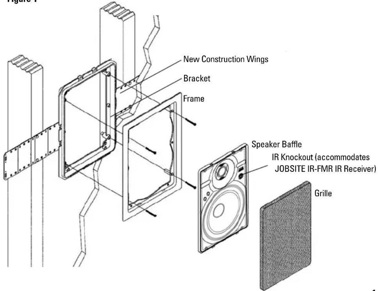
Figure 1
PACKAGE CONTENTS
Speakers x 2
Speaker frames x 2
Speaker grilles x 2
Speaker brackets x 2
Wings for new construction x 4
6 x 1-5/8" Philips head drywall screws x 6
Speaker cutout template
PREPARING FOR INSTALLATION
If you are installing the LSW-6/LSW-6.5 into an existing wall, take time to consider any possible obstructions, which may be hidden inside the wall: studs, electrical wiring, telephone wiring, plumbing, AC or heating conduit and ductwork.
Determine the best mounting locations based on the room layout. Before cutting any holes, make sure the area behind both speakers is clear for installation. Speakers provide the best coverage, when centered in the wall. Choose a suitable mounting height, and then line up both speakers approximately the same distance from the sidewall and ceiling boundaries.
Label the speaker wires at the amplifier location.
TOOLS REQUIRED
■ Stud Locator (for existing construction)
Drywall saw (for existing construction)
Pencil (for existing construction)
■ Cordless screwdriver with No2 Philips bit
1/8" Slotted screwdriver x 2
Wire stripper
Wire labels
INSTALLATION
Installation Existing Construction:
- Using your stud locator, identify the location of the studs on each side of the proposed speaker mounting location.
- Mark their edges, using masking tape.
- Repeat this process for the other speaker.
- You may have to adjust the speaker mounting locations based on how symmetrical the studs are located, in the wall space.
- Check for clearance using the following method.
a. Drill a 1/4" pilot hole in the center of the intended speaker location.
b. Cut a foot-long piece of coat hanger.
c. Bend the wire, creating a right angle, leaving 4-1/4" at one end.
d. Poke the "L-shaped" wire into the pilot hole and turn it in a complete circle, checking for obstructions.
e. Push it into the wall cavity to make sure you have approximately 4" of depth.
f. If the coat hanger movement is obstructed by anything, fill the hole(s) with spackle and try another location.
-
Locate the cutout template.
-
Use a pencil and the cutout template to trace the speaker outline in the desired locations on the wall.
- Use a drywall saw to cut along the penciled line.
-
Slip the mounting bracket through the opening and pull it toward you so that its front edge slides into the hole and stops in place.
-
Attach the frame to the bracket by screwing the frame to the bracket using the supplied screws. NOTE: Do not over tighten the screws, this will distort the frame and the grille will not fit.
- The screws should pull the frame and bracket together (sandwiching the drywall) so that the frame is flush with the wall surface.
- Strip 1/4" of insulation from the end of each wire.
- Tightly twist the end of each wire until no frayed ends remain.
- Attach the speaker wires to the speaker terminal connectors. Connect the negative output from the amplifier to the black terminal. Connect the positive output from the amplifier to the red terminal.
- Insert the speaker into the frame and snap it into place. See figure 2.
- Optional: If you are located in an earthquake zone or want the added security of screwing the speaker baffle to the frame, follow the Important Safety Instructions on page 5.
- Repeat steps 1-16 for each speaker being installed.
- After making tonal adjustments on all speakers (LSW-6.5 only), install the grille into the speaker.

Installation New Construction:
The speaker brackets should be installed prior to the drywall.
- Attach the wings to the bracket by snapping them into the sides of the bracket. (See Figure 1). To shorten the wings, break them along the scored lines.
- The wings and brackets have centering lines to simplify placement of the speaker.
- Use a tape measure to locate and center the brackets in the wall.
- Mark each speaker location with a pencil.
Figure 3

- Screw one side of the assembled bracket with wings to the joist using one of the supplied screws.
- Screw the other side of the bracket/wing assembly to the joist. Two screws on each side make for a very secure installation.
-
Secure the wire to the bracket using the bracket's wire tie.
-
In unique situations where the bracket must be located precisely next to a joist, the bracket has "emergency" screw holes located on its snap-on tabs. Break away two of the outer mounting tabs on the side you wish to affix, see Figure 3. Notching the joist so the bracket lies flush may be required.
- Next, screw the bracket tab to the joist using one of the supplied screws. NOTE: Do not over-tighten the screw, doing so could crack the bracket tab. Level the bracket, then affix the other side of the bracket assembly using the supplied screws.
- After the drywall is installed, cut a hole in the drywall using the outside of the circular bracket flange as a template.
- Attach the frame to the bracket by screwing the frame to the bracket using the supplied screws. NOTE: Do not over tighten the screws, this will distort the frame and the grille will not fit.
-
The screws should pull the frame and bracket together (sandwiching the drywall) so that the frame is flush with the wall surface.
-
Strip 1/4" of insulation from the end of each wire.
- Tightly twist the end of each wire until no frayed ends remain.
- Attach the speaker wires to the speaker terminal connectors. Connect the negative output from the amplifier to the black terminal. Connect the positive output from the amplifier to the red terminal.
- Insert the speaker into the frame and snap it into place. See figure 2.
- Optional: If you are installing the speaker in a ceiling or are located in an earthquake zone or want the added security of screwing the speaker baffle to the frame, follow the Important Safety Instructions on page 5.
- Repeat steps 1-17 for each speaker being installed.
- After making tonal adjustments on all the speakers (LSW-6.5 only), install the grilles into the speakers.
Figure 4

- Locate the dimples on the front baffle.
- Insert the screws through the dimples until they are securely in place.
IMPORTANT SAFETY INSTRUCTIONS
When installing LSW-6, LSW-6.5 speakers in a ceiling or if the installation is located in an earthquake zone, it is recommended that you utilize the enclosed self-tapping screws to secure the baffle to the frame See Figure 4.
DIRECTING THE TWEETER
The tweeter is directed by gently pushing on the edge of the tweeter grille. It will move 20° in any direction. For critical listening point the tweeter to the user's favorite listening position, minimizing reflections from the side walls. For surround sound or low volume background listening create more reflections and thus more ambience by directing the tweeter towards the side walls. See figures 5 and 6.
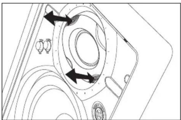
Figure 5
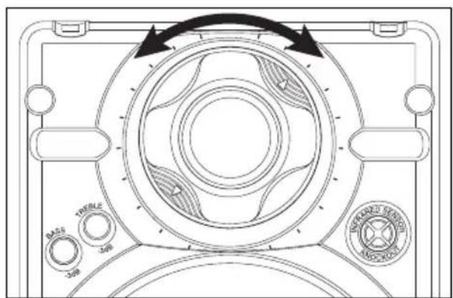
Figure 6
SETTING THE BASS AND TREBLE CUT SWITCHES
LSW-6.5 Loudspeakers ONLY
LSW-6.5 loudspeakers feature separate baffle-mounted bass and treble controls for fine-tuning after installation. Each control provides for approximately 3dB of Bass or Treble reduction. See figure 7.
Listen to a well-recorded piece of music at the user's favorite listening position. First, listen for bass boominess, particularly when the speaker is placed near a corner. Put the Bass switch in the Cut position to correct this. Secondly, listen for treble harshness or ringing, particularly when the speakers are placed in a room without carpet. Put the Treble switch in the Cut position to correct this.

REMOVAL OF GRILLE AND SPEAKER
Removing the Grille
If the grille is already installed, remove it by using a bent paper clip or the tip of a corkscrew and pulling it away from the frame. See figure 8.
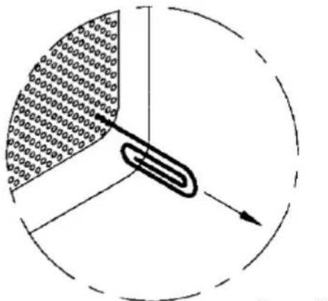
Figure 8
Removing the Speaker
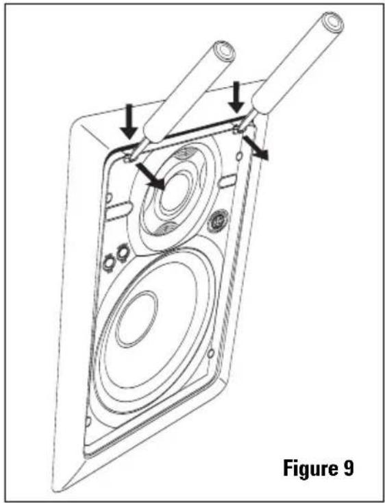
Utilizing two small screwdrivers or two needle nose pliers, release the snaps that hold the speaker to the frame. Insert the screwdrivers into the holes in the snaps and exert force straight down (towards the woofer), until the snaps release. Once the snaps release, the speaker can be tilted away from the frame to be removed. Do not attempt to use the frame for leverage, as this may damage the surface of the frame See Figure 9.
PAINTING THE GRILLE AND FRAME
Painting the Speaker Frame
The speakers must be removed prior to painting the frames.
Painting the Grilles:
The grilles should be painted before they are installed on the speakers. The best results will be obtained by using a spray gun or airless sprayer. Thin the paint, and then apply several light coats. This technique helps prevent clogging of grille holes. Paint both sides of the grille.
OPERATION
Listening at Higher Volumes:
It requires more power to achieve a reasonable volume of sound in a large room than it does in a small room. It is possible to turn the volume so high that the amplifier runs out of power. This creates "clipping" distortion.
Clipping distortion makes treble sound very harsh and unmusical. When you hear harsh sounding treble from any good speaker, turn the volume down immediately! You are much less likely to damage a speaker with a large amplifier because it will be less likely to produce any clipping distortion.
SPECIFICATIONS: LSW-6
Power handing:
10 - 75 watts
Frequency response:
65Hz-20kHz +/- 3dB
Impedance:
8 ohms
Dimensions:
8-3/4" x 11-11/16" outside dimension
7-5/8" x 10-5/8" hole cutout
3-5/8" deep when installed in 1/2" drywall
Warranty:
5 year limited
SPECIFICATIONS: LSW-6.5
Power handing:
10 - 125 watts
Frequency response:
50Hz -21kHz +/- 3dB
Impedance:
6 ohms
Dimensions:
8-3/4" x 11-11/16" outside dimension
7-5/8" x 10-5/8" hole cutout
3-5/8" deep when installed in 1/2" drywall
Warranty:
5 year limited
LIMITED WARRANTY
JobSite Systems ("JOBSITE"), a Niles Audio Corporation company, warrants its passive products (those not requiring AC or battery power) to the original purchaser to be free of manufacturing defects in material and workmanship for a period of ten years from date of purchase.
JOBSITE warrants its passive loudspeaker products (those not requiring AC or battery power) to the original purchaser to be free of manufacturing defects in material and workmanship for a period of five years from date of purchase.
JOBSITE warrants its indoor/outdoor loudspeaker products to the original purchaser to be free of manufacturing defects in material and workmanship for a period of two years from date of purchase.
JOBSITE warrants its all weather rock loudspeaker products to the original purchaser to be free of manufacturing defects in material and workmanship for a period of five years from date of purchase.
JOBSITE warrants its active products (those requiring AC or battery power) to the original purchaser to be free of manufacturing defects in material and workmanship for a period of two years from date of purchase.
This Warranty is subject to the following additional conditions and limitations. The Warranty is void and inapplicable if JOBSITE deems that the product has been used or handled other than in accordance with the instructions provided by the manufacturer, including, but not limited to, damage caused by accident, mishandling, improper installation, abuse, negligence, or normal wear and tear, or any defect caused by repair to the product other than by JOBSITE or an authorized JOBSITE wholesale distributor.
To obtain warranty service, you must write to JOBSITE: Include your name, address, telephone number, model number and serial number of your unit, and a brief description of the problem.
A factory Return Authorization Number will be sent to you. DO NOT RETURN ANY UNIT WITHOUT FIRST RECEIVING WRITTEN AUTHORIZATION AND SHIPPING INSTRUCTIONS FROM JOBSITE.
If the above conditions are met, the purchaser's sole remedy shall be to return the product to JOBSITE, in which case JOBSITE will repair or replace, at its sole option, the defective product without charge for parts or labor. JOBSITE will return the unit repaired or replaced under warranty by shipping it by its usual shipping method from the factory (only) at its expense within the United States of America. THERE ARE NO OTHER WARRANTIES, INCLUDING, WITHOUT LIMITATION, EITHER EXPRESS OR IMPLIED WARRANTIES OF MERCHANTABILITY OR FITNESS FOR A PARTICULAR PURPOSE, WITH RESPECT TO THE PRODUCT.
REPAIR OR REPLACEMENT AS PROVIDED UNDER THIS WARRANTY IS THE EXCLUSIVE REMEDY OF THE CONSUMER/PURCHASER. JOBSITE SHALL NOT BE RESPONSIBLE FOR ANY INCIDENTAL OR CONSEQUENTIAL DAMAGES EXCEPT TO THE EXTENT PROVIDED (OR PROHIBITED) BY APPLICABLE LAW.
Some states do not allow the exclusion or limitation of incidental or consequential damages, so the above limitation may not apply to you. This warranty gives you specific legal rights, and you may also have other rights, which vary from state to state.
For the name of the nearest authorized JOBSITE wholesale distributor, contact:
JobSite Systems, a Niles Audio Corporation company
P.O. Box 160818, Miami, Florida 33116
NOTES:

JOBSITE SYSTEMS
12331 S.W. 130 STREET, MIAMI, FLORIDA 33186
P (866) 4JB-SITE (866-452-7483) - F (305) 238-0185
WWW.JOBSITESYSTEMS.COM
JobSite Systems, a Niles Audio Corporation company, 12331 S.W. 130 Street, Miami, Fl 33186. ©2004 Niles Audio Corporation. JobSite, Pure Custom and Niles are registered trademarks of Niles Audio Corporation and the JobSite Logo is a trademark of Niles Audio Corporation. All other trademarks are the property of their respective owners. Some JobSite products (or components thereof) are manufactured under one or more U.S. Patents, foreign equivalents and/or pending patents (see product for details). Because we constantly strive to improve our products, JobSite reserves the right to change product specifications, descriptions, and prices without notice. The technical and other specifications of information contained herein are not intended to set forth all technical and other specifications of JobSite products. Additional information can be obtained at www.JobSitesystems.com or by calling JobSite at 866-452-7483. Printed in China. 11/04 DS00387ACN
- LSW-6/6.5
- 6-1/2" IN-WALL LOUDSPEAKER
- TABLE OF CONTENTS
- FEATURES: LSW-6
- INSTALLATION FRIENDLY DESIGN
- FEATURES: LSW-6.5
- PRODUCT OVERVIEW
- PACKAGE CONTENTS
- 6 X 1-5/8" PHILIPS HEAD DRYWALL SCREWS X 6
- PREPARING FOR INSTALLATION
- TOOLS REQUIRED
- INSTALLATION
- INSTALLATION EXISTING CONSTRUCTION
- INSTALLATION NEW CONSTRUCTION
- IMPORTANT SAFETY INSTRUCTIONS
- DIRECTING THE TWEETER
- SETTING THE BASS AND TREBLE CUT SWITCHES
- LSW-6.5 LOUDSPEAKERS ONLY
- REMOVAL OF GRILLE AND SPEAKER
- REMOVING THE GRILLE
- REMOVING THE SPEAKER
- PAINTING THE GRILLE AND FRAME
- PAINTING THE SPEAKER FRAME
- PAINTING THE GRILLES
- OPERATION
- LISTENING AT HIGHER VOLUMES
- SPECIFICATIONS: LSW-6
- SPECIFICATIONS: LSW-6.5
- LIMITED WARRANTY
- NOTES
Brand : JobSite
Model : LSW-6.5
Category : Loudspeaker