POPE009501 - Detector Popp - Free user manual and instructions
Find the device manual for free POPE009501 Popp in PDF.

| Product Type | Z-Wave Motion Detector |
| Brand | Popp |
| Model | POPE009501 |
| Dimensions (H x W x D) | 85 x 55 x 45 mm |
| Weight | 50 g |
| Power Supply | 2 x AAA batteries (1.5V) |
| Battery Life | Up to 2 years |
| Wireless Protocol | Z-Wave Plus (868.42 MHz) |
| Detection Range | Up to 12 meters (110° angle) |
| Operating Temperature | 0°C to 40°C |
| Humidity Range | 0% to 85% non-condensing |
| Main Functions | Motion detection, alarm triggering, Z-Wave integration, tamper protection |
| Installation | Wall mount or table placement, screw or adhesive tape |
| Maintenance | Clean with dry cloth; replace batteries when low |
| Safety | CE, RoHS compliant; low battery indicator |
| Spare Parts | Batteries, mounting brackets (available separately) |
| Repairability | Battery replacement only; device is not user-serviceable |
| General Information | Compatible with Z-Wave hubs; supports S2 security; firmware update over the air |
Frequently Asked Questions - POPE009501 Popp
User questions about POPE009501 Popp
0 question about this device. Answer the ones you know or ask your own.
Ask a new question about this device
Download the instructions for your Detector in PDF format for free! Find your manual POPE009501 - Popp and take your electronic device back in hand. On this page are published all the documents necessary for the use of your device. POPE009501 by Popp.
USER MANUAL POPE009501 Popp
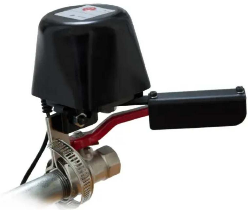
Gas/Water Shut-Off Controller
Manual
natural_image
Close-up of a black industrial valve with red handle and metallic mesh component (no visible text or symbols)Gas/Water Shut-Off Controller – Manual
Quick Start 2
Product Description 2
Installation Guidelines 2
Behavior within the Z-Wave Network 3
Operating the Device....3
Node Information Frame 4
Technical Data 4
Explanation of Z-Wave specific Terms 4
Support 4
Quick Start
This device is a Z-Wave actuator. To include the device, press the red inclusion button on the upper front side 3 times. During includes/excludes it is suggested to keep the device within a distance to the controller less than 1 meter. The two screws must be shut off before include/exclude.
Product Description
Flow Stop is a motor operated shut-off controller for automatic flow stop of gas and water pipes. It is equipped with Z-Wave technology. The Flow Stop is driven by a motor and closes the ball valve mechanically. Even though the Motor requires only 12 Volt (1A), it has a high power output as well as high torque, which reliably closes the ball valve in just 10 seconds. Also a manual closing of valve is easily possible in case of power failure – thanks to the clutch release bearing.
Thanks to the „Flow Stop“, the water supply can
be stopped automatically in the event of overflowing bathtubs, leaking washing machines or defects to water pipelines. This also refers to a gas leak. In this way the Flow Stop is protecting against water and consequential damages reliably.
Installation Guidelines
The POPP Flow Stop is delivered completely including valve control/motor, power supply, mounting and Quick Start Guide and is easy to assembly on the existing ball stop valve. In doing so, all usual pipe standards, including 12 " and 34 ", are possible. On this occasion no pipes must be dismantled or even water must be drained. That way the installation is normally done in 5-10 minutes.
For ductwork user
The main ball valve should be designed and installed to the place as much as convenient for manual opening and closing. The flow stop shut-off controller should keep 20 mm away from the wall.
-
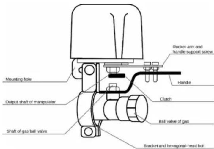
Install the Popp Flow Stop to the ball valve with two semicircular brackets which griped the pipe, and another and fix the mounting hole of the manipulator.
-
Make the bracket with the screw thread in the guide-bar side of the mounting hole by tightening two M6*16 hexagonal-head bolts into the two bolt holes at both ends of the bracket for initial installation, but fix them loosely. Put two rocker arm screw bolts symmetrically to the both sides of the valve handle and tighten two M4 nuts using cross screw driver and 7# spanner.
-
Adjust the three-dimensional position of the bracket to make a coaxial line between the output shaft of the manipulator and the center line of the valve, and then tighten two M6*16 hexagonal-head screws using the 10# fork wrench or box wrench (the socket wrench preferred).
The manipulator could connect ductwork directly, instead of the rocket arm, for connection to the output shaft of the device and the gas ball valve.
To include the device, press the red inclusion button on the upper front side 3 times. During includes/excludes it is suggested to keep the device within a distance to the controller less than 1 meter. The two screws must be shut off before include/exclude.
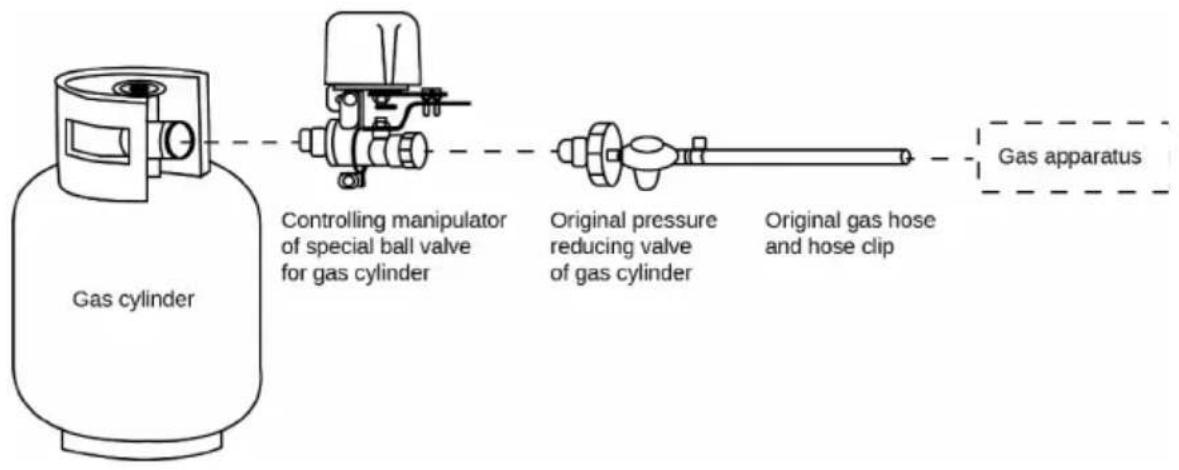
For bottled gas user
To connect bottled gas, the user uninstall the original pressure reducing valve and install the manipulator with the special ball valve for the pipe between the original angle valve and pressure reducing valve, and then tighten it. (See the following procedures)
Behavior within the Z-Wave Network
On factory default the device does not belong to any Z-Wave network. The device needs to join an existing wireless network to communicate with the devices of this network. This process is called Inclusion. Devices can also leave a network. This process is called Exclusion. Both processes are initiated by the primary controller of the Z-Wave network. This controller will be turned into exclusion respective inclusion mode. Please refer to your primary controller's manual on how to turn your controller into inclusion or exclusion mode. Only if the primary controller is in inclusion or exclusion mode, this device can join or leave the network. Leaving the network – i.e. being excluded – sets the device back to factory default. For inclusion/exclusion press the red inclusion button 3 times.
Operating the Device
The Flow Stop can open or shut ball valves at command. Furthermore it sends its status (open/closed) to the controller.
In case of alarm failure, overhaul or power cut:
- pull out the tab of clutch and keep,
- manually turn the handle to the end point until move smoothly,
- release the tab, and then gently move the handle to make the clutch back to its original position.
The Flow Stop is also applicable to automatic control of other gas or fluid valves.
Node Information Frame
The Node Information Frame is the business card of a Z-Wave device. It contains information about the device type and the technical capabilities. The inclusion and exclusion of the device is confirmed by sending out a Node Information Frame. Beside this it may be needed for certain network operations to send out a Node Information Frame.
Every click on the red inclusion button issues a Node Information Frame.
Technical Data
| Voltage | 12 V, 1 A |
| Frequency | 868.42 MHz (SRD Band) |
| Wireless Range | Up to 30 m outside |
| Valve Pressure | 1.6 Mpa |
| Valve size | 1/2", 3/4", 1", 1.25", 1.5" |
| Auto Close Time | 5~10 seconds |
| Auto Open Time | 5~10 seconds |
| Torque | 30~60 Kg.cm |
Explanation of Z-Wave specific Terms
- Controller is a Z-Wave device with capabilities to manage the network. Controllers are typically gateways, remote controls or battery operated wall controllers.
- Slave is a Z-Wave device without capabilities to manage the network. Slaves can be sensors, actuators and even remote controls.
- Primary Controller is the central organizer of the network. It must be a controller. There can be only one primary controller in a Z-Wave network.
- Inclusion is the process of bringing new Z-Wave devices into a network.
- Exclusion is the process of removing Z-Wave devices from the network.
- Association is a control relationship between a controlling device and a controlled device.
- Wake up Notification is a special wireless message issued by a Z-Wave device to announce that is able to communicate.
- Node Information Frame is a special wireless message issued by a Z-Wave device to announce its capabilities and functions.
Support
Should you encounter any problem, please give us an opportunity to address it before returning this product. Most questions regarding Z-Wave wireless communication standard can be answered through the international community at www.z-wave.info.
If your question can't be answered there, please contact us by email: info@popp.eu
© 2015 POPP & Co.
While the information in this manual has been compiled with great care, it may not be deemed an assurance of product characteristics. Popp & Co. shall be liable only to the degree specified in the terms of sale and delivery.
The reproduction and distribution of the documentation and software supplied with this product and the use of its contents is subject to written authorization from Popp & Co. We reserve the right to make any alterations that arise as the result of technical development.
Phone: +44 (0) 20 7419 5726
eMail: info@popp.eu
Web: www.popp.eu