
53-53020-3 - Computer and Other Cables HONEYWELL - Free user manual and instructions
Find the device manual for free 53-53020-3 HONEYWELL in PDF.


| Product Type | Stand Alone Keyboard PowerLink Cable (Accessory for MS1690 Series Scanners) |
| Brand | Honeywell (formerly Metrologic) |
| Model Number | 53-53020-3 |
| Compatible Scanners | MS1690 and MS1691 series (for Stand Alone Keyboard interface) |
| Interface Type | Stand Alone Keyboard (KB) – Keyboard emulation |
| Connector (Scanner End) | 10-pin RJ45 male (locking) |
| Connector (Host End) | 6-pin male Mini-DIN |
| Cable Length | 2.7 m (9 ft) coiled, extends up to approx 2.7 m |
| Cable Type | Coiled cord with long strain relief |
| Color | Black |
| Weight | Approximately 100 g |
| Input Voltage | 5.0 VDC ± 0.25 V (from host or external power supply) |
| Operating Temperature | 0°C to 40°C (32°F to 104°F) |
| Storage Temperature | -40°C to 60°C (-40°F to 140°F) |
| Humidity | 0% to 95% non-condensing |
| Safety Compliance | Designed for use with SELV power sources per EN/IEC 60950-1 |
| Maintenance & Cleaning | Clean with a lint-free cloth lightly dampened with mild glass cleaner (no ammonia); do not immerse in liquid |
| Repairability | Not user-serviceable; replace if defective |
| Warranty | Limited warranty (refer to scanner product manual for details) |
Frequently Asked Questions - 53-53020-3 HONEYWELL
User questions about 53-53020-3 HONEYWELL
0 question about this device. Answer the ones you know or ask your own.
Ask a new question about this device
Download the instructions for your Computer and Other Cables in PDF format for free! Find your manual 53-53020-3 - HONEYWELL and take your electronic device back in hand. On this page are published all the documents necessary for the use of your device. 53-53020-3 by HONEYWELL.
USER MANUAL 53-53020-3 HONEYWELL
METROLOGIC INSTRUMENTS, INC.
MS1690 Focus® Series
Area Imaging Bar Code Scanner Installation and User's Guide

Copyright
© 2008 by Metrologic Instruments, Inc. All rights reserved. No part of this work may be reproduced, transmitted, or stored in any form or by any means without prior written consent, except by reviewer, who may quote brief passages in a review, or provided for in the Copyright Act of 1976.
Trademarks
Metrologic is a registered trademark of Metrologic Instruments, Inc. Products identified in this document are hereby acknowledged as trademarks, registered or otherwise, of Metrologic Instruments, Inc. or their respective companies.
Introduction
Product Overview....1
Scanner and Accessories....2
Scanner Components....4
The PowerLink Cable 5
Labels....6
Maintenance....6
Installing the Scanner to the Host System
RS232 7
Keyboard Wedge....8
Stand Alone Keyboard 9
RS485 10
Full Speed USB (Integrated) 11
Low Speed USB (Integrated).... 11
Stand Kits
Stand Components, MLPN 46-00147....12
Hard Mounting the Stand.... 13
Assembling the Stand 14
Scanner Operation
Two Default Modes of Operation.... 15
Audible Indicators.... 16
Visual Indicators 17
Failure Modes.... 18
MS1690 Depth of Field by Minimum Bar Code Element Width 19
MS1691 Depth of Field by Minimum Bar Code Element Width 20
MS1690 IR Activation Range 21
MS1691 IR Activation Range 22
Troubleshooting Guide 23
Design Specifications 27
Applications and Protocols ...... 29
TABLE OF CONTENTS
Default Settings – Communication Parameters.... 30
Configuration Modes 34
Upgrading the Flash ROM Firmware 35
Scanner and Cable Terminations
Scanner Pinout Connections 36
Cable Connector Configurations 38
Limited Warranty 40
Regulatory Compliance
Safety 41
EMC 42
Patents 44
Index 45
Contact Information and Office Locations....47
Product Overview
Metrologic's MS1690 Focus ® series of high performance hand-held area imaging bar code scanners utilizes high-resolution CMOS imaging sensors for superior image quality. Omniplanar, Inc.'s SwiftDecoder ® software, for reliable decoding of both 1D and 2D bar code symbologies. Sharp images can be captured and transmitted in a variety of outputs including: .jpg, .bmp, and .tiff.
The MS1690 series provides an extended depth of field and a built in object detection sensor (IR) that instantly turns on the scanner when an object is presented within the scanner's field of view. Automatic in-stand detection switches the scanner to a “presentation” mode for convenient in-stand scanning.
| Model Interface | |
| MS1690 – 11 RS485▲, RS232-TXD, RXD, RTS, CTS | |
| MS1690 – 14 or MS1691 – 14 | RS232 (TX, RX, RTS, CTS, DTR) |
| MS1690 – 38 Low Speed USB | |
| MS1690 – 40 Full Speed USB | |
| MS1690 – 47 or MS1691 – 47 | Keyboard Wedge, Stand-Alone Keyboard and RS232 Transmit/Receive |
| MS1690 – 106 or MS1691 – 106 | RS485▲, Full Speed USB, and RS232 Transmit/Receive |
 Decoding and functional capability of the unit is restricted through the use of license numbers provided by Metrologic. Units will not support key features such as, but not limited to, the ability to decode PDF, 2D or OCR fonts without the proper licenses. Desired licenses can be specified at the time of sale or call a Metrologic representative for more information. Standard models ship with the ability to read all 1D, PDF and 2D bar codes. OCR fonts are disabled by default and must be specifically requested at an additional cost. Decoding and functional capability of the unit is restricted through the use of license numbers provided by Metrologic. Units will not support key features such as, but not limited to, the ability to decode PDF, 2D or OCR fonts without the proper licenses. Desired licenses can be specified at the time of sale or call a Metrologic representative for more information. Standard models ship with the ability to read all 1D, PDF and 2D bar codes. OCR fonts are disabled by default and must be specifically requested at an additional cost. | |
▲ Applicable for IBM ® Host applications.
Scanner and Accessories
| BASIC KIT | |
| Part # Description | |
| MS1690 or MS1691 | Area Imaging Bar Code Scanner or Area Imaging HD Bar Code Scanner |
| 00-02544 | MetroSelect® Single-Line Configuration Guide* |
| 00-02281 Supplemental Configuration Guide* | |
| 00-02098 | MS1690 Series Area Imaging Bar Code Scanner Installation and User's Guide* |
* Available on the Metrologic website - www.metrologic.com
| OPTIONAL ACCESSORIES | |
| Part # Description | |
| AC to DC Power Transformer - Regulated 5.2VDC @ 1 A output. | |
| 46-00525 90VAC-255VAC United States, Canada, and Japan | |
| 46-00526 90VAC-255VAC Continental European | |
| 46-00527 90VAC-255VAC United Kingdom | |
| 46-00528 90VAC-255VAC Australia | |
| 46-00529 | 90VAC-255VAC China |
| 53-53000-3-FR | RS232 PowerLink Cable with Built in Power Jack coiled cord, long strain relief, black with ferrite |
| 53-53002-3 | Keyboard Wedge PowerLink Cable with Adapter Cable coiled cord, long strain relief, black |
| 53-53020-3 | Stand Alone Keyboard PowerLink Cable coiled cord, long strain relief, black |
Other items may be ordered for the specific protocol being used. To order additional items, contact the dealer, distributor or call Metrologic's Customer Service Department at 1-800-ID-METRO or 1-800-436-3876.
Scanner and Accessories
| OPTIONAL ACCESSORIES | |
| Part # Description | |
| 53-53213x-N-3-FR | USB Full Speed Cable, Locking Plus-PowerTM Type A, coiled cord, long strain relief, black with ferrite |
| 53-53214x-N-3-FR | USB Full Speed Cable, Locking Plus-PowerTM Type A, coiled cord, long strain relief, black with ferriteThis cable is for use with full speed USB (-40) interface only. |
| 53-53235x-N-3-FR | USB Low Speed Communication Cable Type A, coiled cord, long strain relief, black with ferrite |
| MVC-2MPC-IB9 | RS485▲ ApplicationsMetrologic Voltage Converter (MVC) Cable* ±12VDC to +5.2VDC |
| MVC-3M106C-IB9 | RS485▲ ApplicationsMetrologic Voltage Converter (MVC) Cable* ±12VDC to +5.2VDC |
| * Contact a Metrologic customer service representative for additional information on the MVC cable series and the host connections available. | |
| 00-02001 MS1690 Stand (46-00147) Installation Guide | |
| 46-00147 Modular Presentation Stand | |
Other items may be ordered for the specific protocol being used. To order additional items, contact the dealer, distributor or call Metrologic's Customer Service Department at 1-800-ID-METRO or 1-800-436-3876.
▲ Applicable for IBM ® Host applications.
Scanner Components

Figure 1. Scanner Components
| Item Description | ||||
| 1 | Yellow | LED | See | Visual Indicators (on page 16) |
| 2 | White | LED | See | Visual Indicators (on page 16) |
| 3 | Blue | LED | See | Visual Indicators (on page 16) |
| 4 | Speaker | See | Audible Indicators (on page 16) | |
| 5 | Trigger | |||
| 6 | Red Window | LED Aperture | ||
| 7 | Cable | Release | See | The PowerLink Cable (on page 16) |
| 8 | Cable | Connection | 10-pin RJ45, Female Socket,See Scanner Pinout Connections (on page 36) | |
The PowerLink Cable
Connecting

Important: If the PowerLink cable is not fully 'latched' the unit can power intermittently.
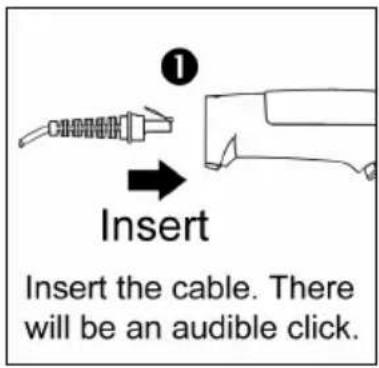

Figure 2. Figure 3.
Disconnecting
Before removing the cable from the scanner, Metrologic recommends that the power on the host system is off and the power supply has been disconnected from the PowerLink cable.

Figure 4. Releasing the PowerLink Cable
-
Locate the small 'pin-hole' on the handle of the unit near the cable.
-
Bend an ordinary paperclip into the shape shown above.
-
Insert the paperclip (or other small metallic pin) into the small 'pin-hole'.
-
There will be a faint 'click' when the lock is released. Pull gently on the strain-relief of the PowerLink cable to remove the cable from the unit.
Labels
Each scanner has a label located on the underside of the head. This label provides the unit's model number, date of manufacture, serial number, CE and caution information. The following figure gives an example of the label and its location.

Figure 5. Label Sample and Location

Caution:
To maintain compliance with applicable standards, all circuits connected to the scanner must meet the requirements for SELV (Safety Extra Low Voltage) according to EN/IEC 60950-1.
To maintain compliance with standard CSA-C22.2 No. 60950-1/UL 60950-1 and norm EN/IEC 60950-1, the power source should meet applicable performance requirements for a limited power source.
Maintenance
Smudges and dirt on the unit's window can interfere with the unit's performance. If the window requires cleaning, use only a mild glass cleaner containing no ammonia. When cleaning the window, spray the cleaner onto a lint free, non-abrasive cleaning cloth then gently wipe the window clean.
If the unit's case requires cleaning, use a mild cleaning agent that does not contain strong oxidizing chemicals. Strong cleaning agents may discolor or damage the unit's exterior.
RS232
- Turn off the host device.
- Plug the male 10-pin RJ45 end of the PowerLink cable into the 10-pin socket on the scanner. There will be an audible click when the connector lock engages.
- Connect the 9-pin D-type connector of the communication cable to the proper COM port of the host device.
- Plug the power supply into the power jack on the PowerLink cable.

Check the AC input requirements of the power supply to verify the voltage matches the AC outlet. The outlet must be located near the equipment and be easily accessible.
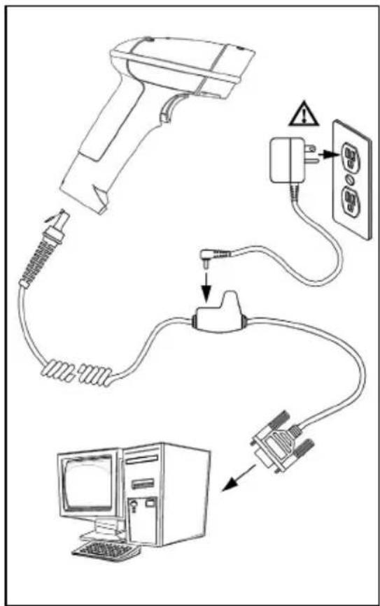
Figure 6.
-
Connect AC power to the transformer.
-
The scanner will start to initialize. All LEDs (yellow, white, and blue) will light for approximately two seconds then start to alternately flash. When the scanner has finished initializing the LEDs will stop flashing and the unit will beep three times indicating that the scanner is ready for use.
-
Turn on the host device.

Plugging the scanner into a port on the host system does not guarantee that scanned information will be communicated properly to the host system. The scanner is shipped from the factory configured with default settings. Please refer to the MetroSelect Single-Line Configuration Guide (MLPN 00-02544) or MetroSet2's help files for instructions on changing the scanner's configuration. In addition, please check that the scanner and host system are using the same communication protocol.

See power source caution statement located on page 6 of this manual.
Keyboard Wedge
- Turn off the host device.
-
Plug the 10-pin RJ45 male end of the PowerLink cable into 10-pin socket on the scanner. There will be an audible click when the connector lock engages.
-
Disconnect the keyboard from the host device.
-
Connect the "Y" ends of the communication cable to the keyboard and keyboard port on the host device. If necessary use the male/female adapter cable supplied with the scanner for proper connections.
-
Plug the external power supply (required) into the power jack on the PowerLink cable.

Check the AC input requirements of the power supply to verify the voltage matches the AC outlet. The outlet must be located near the equipment and be easily accessible.

Figure 7.
-
Connect AC power to the transformer.
-
The scanner will start to initialize. All LEDs (yellow, white, and blue) will light for approximately two seconds then start to alternately flash. When the scanner has finished initializing the LEDs will stop flashing and the unit will beep three times indicating that the scanner is ready for use.
-
Turn on the host device.

Plugging the scanner into a port on the host system does not guarantee that scanned information will be communicated properly to the host system. The scanner is shipped from the factory configured with default settings. Please refer to the MetroSelect Single-Line Configuration Guide (MLPN 00-02544) or MetroSet2's help files for instructions on changing the scanner's configuration. In addition, please check that the scanner and host system are using the same communication protocol.

See power source caution statement located on page 6 of this manual.
Stand Alone Keyboard
- Turn off the host device.
- Plug the male 10-pin RJ45 end of the PowerLink cable into the 10-pin socket on the scanner. There will be an audible click when the connector lock engages.
- Plug the other end of the communication cable into the host's keyboard port.
- Plug the external power supply into the power jack on the PowerLink cable.

Check the AC input requirements of the power supply to verify the voltage matches the AC outlet. The outlet must be located near the equipment and be easily accessible.

Figure 8.
-
Connect AC power to the transformer.
-
The scanner will start to initialize. All LEDs (yellow, white, and blue) will light for approximately two seconds then start to alternately flash. When the scanner has finished initializing the LEDs will stop flashing and the unit will beep three times indicating that the scanner is ready for use.
-
Turn on the host device.

Plugging the scanner into a port on the host device does not guarantee that scanned information will be communicated properly to the host device. The scanner is shipped from the factory configured with default settings. Please refer to the MetroSelect Single-Line Configuration Guide (MLPN 00-02544) or MetroSet2's help files for instructions on changing the scanner's configuration. In addition, please check that the scanner and host system are using the same communication protocol.

See power source caution statement located on page 6 of this manual.
RS485
- Turn off the host device.
- Plug the male 10-pin RJ45 end of the MVC cable into the 10-pin socket on the scanner. There will be an audible click when the connector lock engages.
- Connect the other end of the MVC cable to the host device.
- Turn on the host device.
- The scanner will start to initialize. All LEDs (yellow, white, and blue) will light for approximately two seconds then start to alternately flash. When the scanner has finished initializing the LEDs will stop flashing and the unit will beep three times indicating that the scanner is ready for use.
![graph TD A["MVC Cable"] --> B["Microsingle"] B --> C["Host end connection is application dependent."]](/content/2026/05/1127052/images/e4fffa753473fa7952c753896af33d8360a6c06b0ba404445b440295e490b287.jpg)
Figure 9.
▲ Applicable for IBM ® Host applications.

Plugging the scanner into a port on the host system does not guarantee that scanned information will be communicated properly to the host system. The scanner is shipped from the factory configured with default settings. Please refer to the MetroSelect Single-Line Configuration Guide (MLPN 00-02544) or MetroSet2's help files for instructions on changing the scanner's configuration. In addition, please check that the scanner and host system are using the same communication protocol.

See power source caution statement located on page 6 of this manual.
Integrated USB: Full Speed (- 40 or - 106) Low Speed (- 38)
- Turn off the host device.
- Plug the male 10-pin RJ45 end of the USB cable into the 10-pin socket on the scanner. There will be an audible click when the connector lock engages.
- Plug the USB type A end of the USB cable into the host's USB port.
- Turn on the host device.
- The scanner will start to initialize. All LEDs (yellow, white, and blue) will light for approximately two seconds then start to alternately flash. When the scanner has finished initializing the LEDs will stop flashing and the unit will beep three times indicating that the scanner is ready for use.
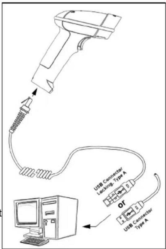
Figure 10.

As a default, the MS1690-38 leaves the factory with USB Keyboard Emulation Mode enabled.
For information on configuring the MS1690-38 for USB Serial Emulation Mode, please refer to the USB section of the MetroSelect Single-Line Configuration Guide (MLPN 00-02544).

Plugging the scanner into a port on the host device does not guarantee that scanned information will be communicated properly to the host device. The scanner is shipped from the factory configured with default settings. Please refer to the MetroSelect Single-Line Configuration Guide (MLPN 00-02544) or MetroSet2's help files for instructions on changing the scanner's configuration. In addition, please check that the scanner and host system are using the same communication protocol.

See power source caution statement located on page 6 of this manual.
Stand Components, MLPN 46-00147

Figure 11. Stand Components
| Item | Description Qty. | |
| a. | Stand Base Qty. 1 | |
| b. | Flexible Shaft Qty. 1 | |
| c. | Flexible Shaft Cover Qty. 1 | |
| d. | Scanner Cradle Qty. 1 | |
| e. | 1/4 " – 20 x 3/8" Flat Head Phillips, 100° Undercut Qty. 2 | |
| f. | #8 Round Head Wood Screw Qty. 2 |
Hard Mounting the Stand (Optional)
Metrologic provides two #8 wood screws for securing the stand base to the counter top. The following figure provides the pilot hole dimensions for securing the stand base.

Figure 12. Stand Base Hole Pattern (Not to Scale)
Assembling the Stand
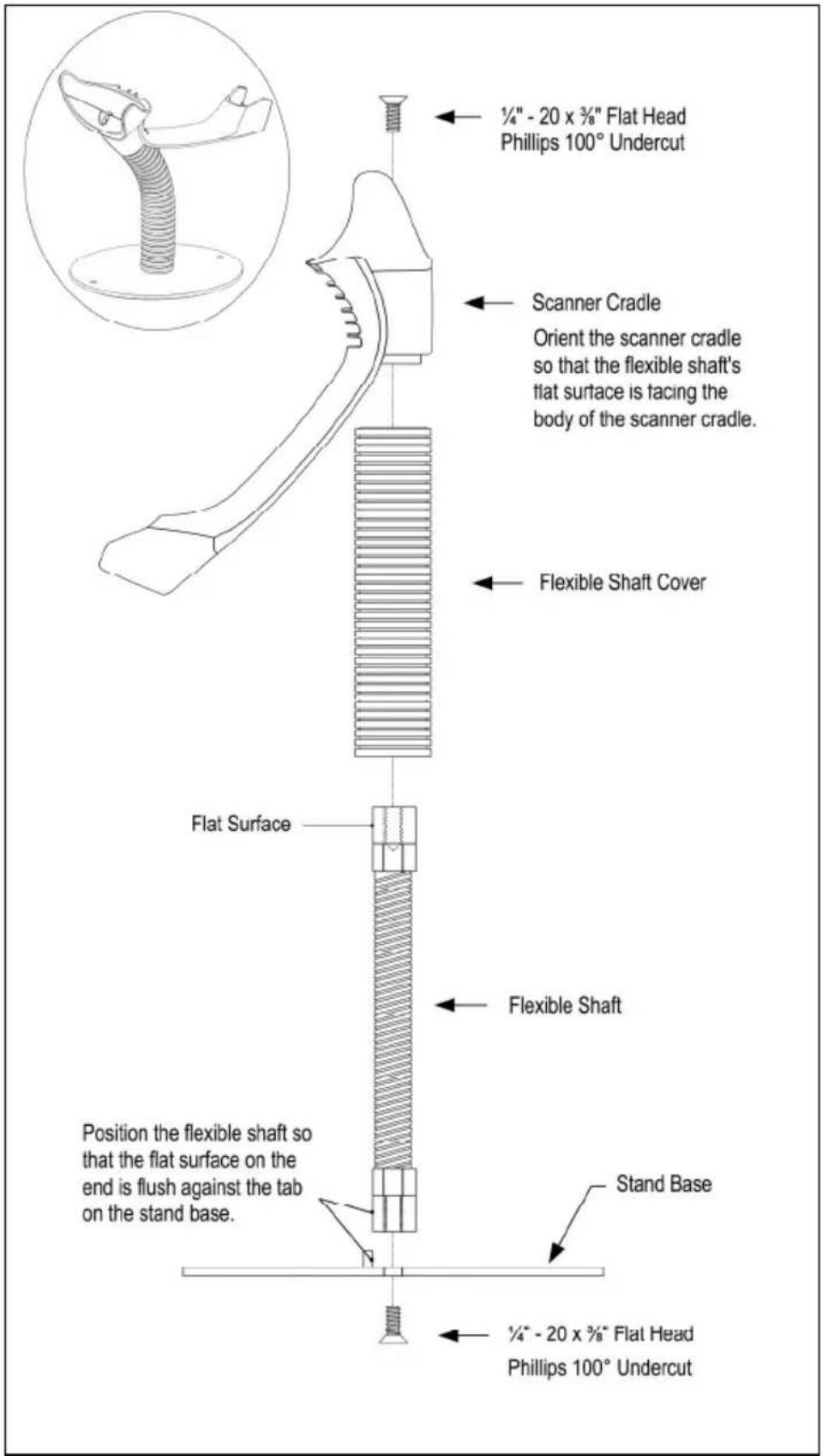
Figure 13. Assembling the Stand
Two Default Modes of Operation\*
Multi-Trigger, Out of Stand
- The IR detects an object in the IR activation range and automatically turns on linear illumination.
- Aim the scanner's line of light over the bar code.
- Pull the trigger to initiate scanning. The scanner's light output will start to flash as it attempts to scan the bar code.

If the trigger is released the scanner will stop trying to scan.
- When scanner successfully reads the bar code it will beep once, the white LED will flash and the decoded data will be transmitted to the host.

Figure 14. Multi-Trigger, Out-of-Stand
Presentation, In-Stand
- The IR detects an object in the IR activation range and the scanner's light output automatically starts to flash as it attempts to scan the bar code.
- The scanner continuously attempts to scan the bar code until either it succeeds or the bar code is removed from the scanner's field of view.
- When scanner successfully reads the bar code it will beep once, the white LED will flash and the decoded data will be transmitted to the host.
* For additional configurable modes of operation, please refer to the Area Imaging Bar Code Supplemental Configuration Guide (MLPN 00-02281).
Audible Indicators
When the MS1690 series scanner is in operation, the scanner provides audible feedback. These sounds indicate the status of the scanner. Eight settings are available for the tone of the beep (normal, 6 alternate tones and no tone). To change the tone, refer to the MetroSelect Single-Line Configuration Guide, MLPN 00-02544 or MetroSet2's help files.
One Beep
When the scanner successfully reads a bar code it will beep once and the white LED will turn on indicating data is being transmitted.
If the scanner does not beep once and the white light does not turn on, then the bar code has not been successfully read.
Short Razzberry Tone
This tone is a failure indicator (see Failure Modes on page 18).
Long Razzberry Tone
This tone is a failure indicator (see Failure Modes on page 18).
Three Beeps - At Power Up
When the scanner first receives power it will start an initialization sequence. All LEDs (yellow, white, and blue) will light for approximately two seconds then start to alternately flash. When the scanner has finished initializing the LEDs will stop flashing and the unit will beep three times indicating that the scanner is ready for use.
Three Beeps - Configuration Mode
When entering configuration mode, the white LED will flash while the scanner simultaneously beeps three times. The white and blue LEDs will continue to flash while in this mode. Upon exiting configuration mode, the scanner will beep three times, and the LEDs will stop flashing.
When configured, three beeps can also indicate a communications timeout during normal scanning mode.
When using single-code-configuring, the scanner will beep three times: a normal tone followed by a short pause, a high tone and then a low tone. This indicates that the single configuration bar code has successfully configured the scanner.
Visual Indicators
The MS1690 series scanner has three LED indicators (yellow, white and blue) located on the top of the scanner. When the scanner is on, the flashing or stationary activity of the LEDs indicates the status of the current scan and the scanner.
No LEDs are Illuminated
The LEDs will not be illuminated if the scanner is not receiving power from the host or transformer.
The scanner is in stand-by mode. Present a bar code to the scanner and the blue LED will turn on when the IR detects the object.

Figure 15.
Steady Yellow
The yellow LED is illuminated when the scanner is in the stand.
Steady Blue
The blue LED is illuminated when the scanner is active and linear illumination is on or when the scanner is attempting to decode a bar code.
Steady Blue and Single White Flash
When the scanner successfully reads a bar code it will beep once and the white LED will turn on indicating data is being transmitted.
If the scanner does not beep once and the white light does not turn on, then the bar code has not been successfully read.
Steady White
When the scanner successfully reads a bar code it will beep once and the white LED will turn on indicating data is being transmitted.

After a successful scan, the scanner transmits the data to the host device. Some communication modes require that the host inform the scanner when data is ready to be received. If the host is not ready to accept the information, the scanner's white LED will remain on until the data can be transmitted.
Alternating Flashing of Blue and White
This indicates the scanner is in configuration mode. A short razzberry tone indicates that an invalid bar code has been scanned while in this mode.
Flashing Blue
The blue LED will flash if the trigger is pressed while the scanner is in the in-stand presentation mode. The blue LED will stop flashing after a brief period of time.
Failure Modes
Long Razzberry Tone – During Power Up
Failed to initialize or configure the scanner. If the scanner does not respond after reprogramming, return the scanner for repair.
Short Razzberry Tone – During Scanning
An Invalid bar code has been scanned when in configuration mode.
MS1690 Depth of Field by Minimum Bar Code Element Width

| MINIMUM BAR CODE ELEMENT WIDTH | |||||||
| 1D PDF | |||||||
| A | B | C | D | E | F G | ||
| mm | .132 | .19 | .254 | .33 | .533 | .254 .381 | |
| mils | 5.2 | 7.5 | 10.4 | 13 | 21 10 15.9 | ||
Figure 16. MS1690 Depth of Field by Minimum Bar Code Element Width

Decoding and functional capability of the unit is restricted through the use of license numbers provided by Metrologic. Units will not support key features such as, but not limited to, the ability to decode PDF, 2D or OCR fonts without the proper licenses. Desired licenses can be specified at the time of sale or call a Metrologic representative for more information. Standard models ship with the ability to read all 1D, PDF and 2D bar codes. OCR fonts are disabled by default and must be specifically requested at an additional cost.
Specifications are subject to change without notice.
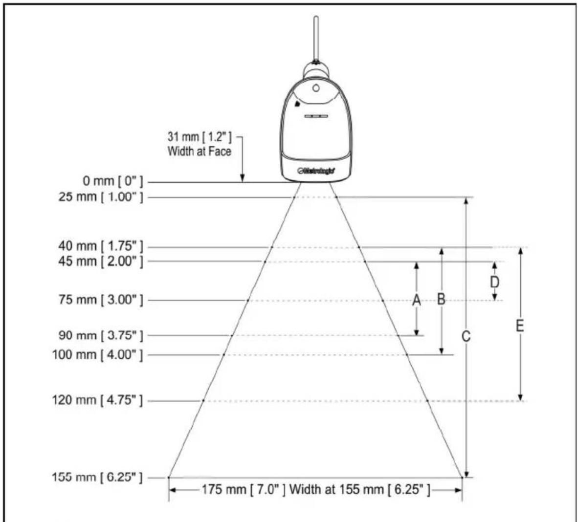
MS1691 Depth of Field by Minimum Bar Code Element Width
| MINIMUM BAR CODE ELEMENT WIDTH | |||||
| 1D Data Matrix | |||||
| A | B | C | DE | ||
| mm | .102 | .127 | .330 .127 .19 | 1 | |
| mils | 4.0 | 5.0 | 13 5.0 7.5 | ||
Figure 17. MS1691 Depth of Field by Minimum Bar Code Element Width

Decoding and functional capability of the unit is restricted through the use of license numbers provided by Metrologic. Units will not support key features such as, but not limited to, the ability to decode PDF, 2D or OCR fonts without the proper licenses. Desired licenses can be specified at the time of sale or call a Metrologic representative for more information. Standard models ship with the ability to read all 1D, PDF and 2D bar codes. OCR fonts are disabled by default and must be specifically requested at an additional cost.
Specifications are subject to change without notice.
MS1690 IR Activation Range
The MS1690 scanner has a built in object detection sensor that instantly turns on the scanner when an object is presented within the scanner's IR activation Area.
![19 mm [.75"] 127 mm [.50"] Width At Window Short IR Activation Area 102 mm [ 4.00" ] Long IR Activation Area 203 mm [ 8.00" ] 9.5 mm [.375"] 6.4 mm [.25"] Width At 1.0" from Window Short IR Activation Area 102 mm [ 4.00" ] Long IR Activation Area 203 mm [ 8.00" ]](/content/2026/05/1127052/images/8a394477531b871bfda71ea62847ee808d4c2fc822a18551f8a440bd8c642996.jpg)
Figure 18. MS1690 IR Activation Area
Specifications are subject to change without notice.
MS1691 IR Activation Range
The MS1691 scanner has a built in object detection sensor that instantly turns on the scanner when an object is presented within the scanner's IR activation Area.
![19 mm [.75"] 127 mm [.50"] Width At Window Short IR Activation Area 102 mm [ 4.00" ] Long IR Activation Area 150 mm [ 6.00" ] 9.5 mm [.375"] 6.4 mm [.25"] Width At 1.0" from Window Short IR Activation Area 102 mm [ 4.00" ] Long IR Activation Area 150 mm [ 6.00" ]](/content/2026/05/1127052/images/90e5b1755041c944cbebf928e0b8a5c7f6715d06ac2f681e0281d5d863633999.jpg)
Figure 19. MS1691 IR Activation Area
Specifications are subject to change without notice.
The following guide is for reference purposes only. Contact a Metrologic representative at 1-800-ID-Metro or 1-800-436-3876 to preserve the limited warranty terms.
All Interfaces
| MS1690 Series Troubleshooting Guide | ||
| Symptoms Possible Causes Solution | ||
| No LEDs, beep or illumination | No power is being supplied to the scanner. | Check transformer, outlet and power strip. Make sure the cable is plugged into the scanner. |
| No power is being supplied to the scanner from the host. | Some host systems cannot supply enough current to power The MS1690. A power supply may be required. | |
| Long Razz tone on power up | The wrong communication cable has been used. | Check that the communication cable matches the unit type and scanner configuration. |
| There has been a scanner configuration failure. | Contact a Metrologic service representative, if the unit will not hold the saved configuration. | |
| There has been a diagnostic failure. | Contact a Metrologic service representative, if the unit will not function. | |
| Long Razz tone when exiting configuration mode | There was a failure saving the new configuration. | Re-try to configure the scanner. Contact a Metrologic Service Representative if the unit will not hold the saved configuration. |
| Long Razz tone | There is a scanning mechanism failure. | Contact a Metrologic service representative. |
| Short Razz tone in configuration mode | An invalid bar code has been scanned. | Scan a valid bar code or quit configuration mode. |
| Symptoms Possible Causes Solution | ||
| The unit powers up, but does not beep when bar code is scanned. | The beeper is disabled and no tone is selected. | Enable the beeper and select a tone. |
| The unit powers up, but does not scan and/or beep. | The bar code symbology trying to be scanned is not enabled. | UPC/EAN, Code 39, interleaved 2 of 5, Code 93, Code 128, Codabar and PDF are enabled by default. Verify that the type of bar code being read has been selected. |
| The unit powers up, but does not scan and/or beep. | The scanner is trying to scan a bar code that does not match the configured criteria. | Verify that the bar code being scanned falls into the configured criteria (i.e. character length lock or minimum bar code length settings). |
| The following item is only relevant for RS232 and USB interfaces. | ||
| The unit scans a bar code, but locks up after the first scan and the white LED stays on. | The scanner is configured to support some form of host handshaking but is not receiving the signal. | If the scanner is setup to support ACK/NAK, RTS/CTS, or XON/XOFF, verify that the host cable and host are supporting the handshaking properly. |
| The unit scans, but the data transmitted to the host is incorrect. | The scanner's data format does not match the host system requirements. | Verify that the scanner's data format matches that required by the host. Make sure that the scanner is connected to the proper host port. |
| The unit beeps at some bar codes and NOT for others of the same bar code symbology. | The bar code may have been printed incorrectly. | Check if it is a check digit/character/ or border problem. |
| The scanner is not configured correctly for this type of bar code. | Check if check digits are set properly. | |
| The minimum symbol length setting does not work with the bar code. | Check if the correct minimum symbol length is set. | |
| The unit scans the bar code but there is no data. | The configuration is not set correctly. | Make sure the scanner is configured for the appropriate mode. |
| The following four items are only relevant for a Keyboard Wedge interface. | ||
| The unit scans but the data is not correct. | The configuration is not set correctly. | Make sure that the proper PC type AT, or PS2 is selected. Verify correct country code and data formatting are selected. Adjust inter-character delay symptom. |
| The scanner and host may not be configured for the same interface parameters. | Check that the scanner and the host are configured for the same interface parameters. | |
| The unit is transmitting each character twice. | The configuration is not set correctly. | Increase interscan code delay setting. Adjust whether the F0 break is transmitted. It may be necessary to try this in both settings. |
| Alpha characters show as lower case. | The computer is in Caps Lock mode. | Enable Caps Lock detect setting of the scanner to detect if the PC is operating in Caps Lock. |
| Everything works except for a couple of characters. | These characters may not be supported by that country's key look up table. | Try operating the scanner in Alt mode. |
| The following items are only relevant for an RS232 interface. | ||
| The unit powers up OK and scans OK but does not communicate properly with the host. | The com port at the host is not working or not configured properly. | Check to make sure that the baud rate and parity of the scanner and the communication port match and the program is looking for "RS232" data. |
| The cable is not connected to the correct com port. | Check to make sure that the cable is connected to the correct com port. | |
| Characters are being dropped. | Inter-character delay needs to be added to the transmitted output. | Add some inter-character delay to the transmitted output by using the Configuration Guides (MLPN 00-02544 and 00-02281). |
| MS1690 SERIES DESIGN SPECIFICATIONS | ||||
| OPERATIONAL | ||||
| Light Source: | LED 645 nm | |||
| Pulse Duration: | 10 μs to 8000 μs | |||
| Maximum Output: | 0.76 mW peak | |||
| Depth of Scan Field: | MS1690 0 | mm – 330 mm (0" – 13") | 0.330 mm (13 mil) Bar Code | |
| MS1691 25 mm – 155 mm (1" – 6.25") | ||||
| Field of View: | 49 mm W x 19 mm H (1.9" W x 0.8" H) at 20 mm (0.8") | |||
| 264 mm x 106 mm (10.4" W x 4.2" H) at 280 mm (11.0") | ||||
| Minimum Bar Width: | MS1690 | 0.038 mm (3.5 mil) 1D,0.254 mm (10.0 mil) 2D | ||
| MS1691 | 0.102 mm (4.0 mil) 1D,0.127 mm (5.0 mil) Data Matrix | |||
| Infrared Activation: | MS1690 | Long 0 | mm – 203 mm (4" – 8") | From Window |
| Short 0 | mm – 101 mm (0" – 4") | |||
| MS1691 | Long 0 | mm – 150 mm (4" - 6") | ||
| Short 0 | mm – 101 mm (0" – 4") | |||
| Motion Tolerance: | 47 cm/sec (18"/sec) 100% UPC in stand | |||
| Decode Capability: | Autodiscriminates All Standard 1-D, GS1 Databar, PDF417, microPDF, MaxiCode, Data Matrix, QR Code, UCC, EAN Composites, Postals, Aztec | |||
| Image Transfer*: | BMP, TIFF, or JPEG output*RS232 and USB only | |||
| System Interfaces: | PC Keyboard Wedge, RS232, RS485▲, Stand Alone Keyboard, USB (Low Speed and Full Speed)▲ Applicable for IBM® Host applications. | |||
| Print Contrast: | 20% Minimum Reflectance Difference | |||
| Number Characters Read: | Up to 80 Data Characters on 1D;1850 Text Characters for PDF417 | |||
| Beeper Operation: | 7 tones or no beep | |||
| Indicators (LED)Default Settings: | Blue Unit Powered, Ready to Scan | |||
| White | Good Read | |||
| Yellow | In Stand | |||
Specifications are subject to change without notice.
| MS1690 SERIES DESIGN SPECIFICATIONS | |
| MECHANICAL | |
| Height: | 183 mm (7.2") |
| Width: | Handle 30 mm (1.2") |
| Head 79 mm (3.1") | |
| Depth: | 111 mm (4.9") |
| Weight: | 225 g (8.0 oz) |
| Termination: | 10 pin modular RJ45 |
| Cable: | Standard 2.7 m (9') Coiled; Optional 2.1 m (7') Straight |
| ELECTRICAL | |
| Input Voltage: | 5.0VDC ± 0.25V |
| Power: | Peak = 2 W (Typical) |
| Operating = 1.65 W (Typical) | |
| Idle / Standby = 800 mW (Typical) | |
| Current: | Peak = 400 mA (Typical) |
| Operation = 330 mA (Typical) | |
| Idle / Standby = 160 mA (Typical) | |
| DC Transformer: | Class 2; 5.2VDC @ 1 A |
| For Regulatory Compliance information, see pages 41 - 43. | |
| ENVIRONMENTAL | |
| Temperature: | Operating = 0°C to 40° (32° to 104°F) |
| Storage = -40°C to 60°C (-40°F to 140°F) | |
| Humidity: | 0% to 95% Relative Humidity, Non-Condensing |
| Light Levels: | Up to 100,000 Lux (9,290 Footcandles) |
| Shock: | Designed to withstand 1.5 m (5 ft.) drops |
| Contaminants: | Sealed to resist airborne particulate contaminants |
| Ventilation: | None required |
Specifications are subject to change without notice.
The model number on each scanner includes the scanner number and factory default communications protocol.
| SCANNER | VERSION IDENTIFIER | COMMUNICATION PROTOCOL(S) |
| MS1690 | 11 | RS485▲, RS232-TXD, RXD, RTS, CTS |
| MS1690 or MS1691 | 14 RS232 (TX, RX, RTS, CTS, DTR) | |
| MS1690 | 38 Low Speed USB | |
| MS1690 | 40 | Full-speed USB |
| MS1690 or MS1691 | 47 | Keyboard Wedge, Stand-Alone Keyboard and RS232 Transmit/Receive |
| MS1690 or MS1691 | 106 | RS485▲, Full Speed USB, and RS232 Transmit/Receive |
▲ Applicable for IBM ® Host applications.
The MS1690-47 and MS1691-47 with a built-in PC Keyboard Wedge Interface is designed for Keyboard emulation use only. Many RS232 configurable functions available in other Metrologic scanners are also available as keyboard wedge functions.
The following are the most important selectable options specific to the keyboard wedge.
Keyboard Type
- **AT (includes IBM® PS2 models 50, 55, 60, 80)
• IBM PS2 (includes models 30, 70, 8556)
Keyboard Country Type
- **USA
- Belgium
- French
- German
- Hungarian
- Italian
- Japanese
• Russian Cyrillic - Slovenian
- Spanish
- Swiss
- Swedish/Finnish
- Turkish
• United Kingdom
** For additional information on the MS1690 series default settings refer to pages 30-33. For information on how to change the default settings, refer to help files in MetroSet2 or the MetroSelect Single-Line Configuration Guide (MLPN 00-02544).
Many functions of the scanner can be “configured” – that is, enabled or disabled. The scanner is shipped from the factory configured to a set of default conditions. The default parameter of the scanner has an asterisk (*) in the charts on the following pages. If an asterisk is not in the default column then the default setting is OFF or DISABLED. Every interface does not support every parameter. If the interface supports a parameter listed in the charts on the following pages, a check mark (√) will appear.
| PARAMETER DEFAULT RS232 RS485 | ▲ KBW USB | ||
| Multi-Try Trigger Out-of-Stand * | ✓ | ✓ ✓ | |
| Presentation Mode In-Stand * | ✓ | ✓ ✓ | |
| Continuous Trigger | ✓ | ✓ ✓ | |
| Single Trigger | ✓ | ✓ ✓ | |
| Aiming in Trigger and Continuous Modes | * | ✓ | ✓ ✓ |
| Aiming in Presentation Mode | ✓ | ✓ ✓ | |
| Long-Range In-Stand * | ✓ | ✓ ✓ | |
| Short-Range In-Stand | ✓ | ✓ ✓ | |
| Long-Range Out-of-Stand * | ✓ | ✓ ✓ | |
| Short-Range Out-of-Stand | ✓ | ✓ ✓ | |
| UPC/EAN * | ✓ | ✓ ✓ | |
| Code 128 * | ✓ | ✓ ✓ | |
| Code 93 | * | ✓ | ✓ ✓ |
| Codabar | * | ✓ | ✓ ✓ |
| Interleaved 2 of 5 (ITF) | * | ✓ | ✓ ✓ |
| MOD 10 check on ITF | ✓ | ✓ ✓ | |
| Code 11 | ✓ | ✓ ✓ | |
| Code 39 | * | ✓ | ✓ ✓ |
| Full ASCII Code 39 | ✓ | ✓ ✓ | |
| * | ✓ | ✓ ✓ | |
| Data Matrix | ✓ | ✓ ✓ | |
| QR Code | ✓ | ✓ ✓ |
▲ Applicable for IBM ® Host applications.
| PARAMETER DEFAULT RS232 RS485 | ▲ KBW USB | |||
| Maxicode | √ | √ √ | √ | |
| Aztec | √ | √ √ | √ | |
| Postals | √ | √ √ | √ | |
| Mod 43 Check on Code 39 | √ | √ √ | √ | |
| MSI-Plessy 10/10 Check Digit | √ | √ √ | √ | |
| MSI-Plessy Mod 10 Check Digit * | √ | √ √ | √ | |
| Paraf Support ITF | √ | √ √ | √ | |
| ITF Symbol Lengths Variable | √ | √ √ | √ | |
| Symbol Length Lock None | √ | √ √ | √ | |
| Beeper tone | Normal | √ | √ √ | √ |
| Beep/transmit sequence | Before transmit | √ | √ √ | √ |
| Communication timeout | None | √ | √ √ | √ |
| Razzberry tone on timeout | √ | √ √ | √ | |
| Three beeps on timeout | √ | √ √ | √ | |
| Same symbol rescan timeout: 1000 msecs | * | √ | √ √ | √ |
| Same symbol rescan timeout configurable in 50 msec steps (maximum of 6.35 sec.) | √ | √ √ | √ | |
| No Same symbol timeout | √ | √ √ | √ | |
| Infinite Same symbol timeout | √ | √ √ | √ | |
| Inter-character delay configurable in 1 msec steps (maximum of 255 msecs) | 1 msecs 10 msecs in KBW | √ | √ √ | √ |
| Number of scan buffers (maximum) | 8 | √ | √ √ | √ |
| Transmit UPC-A check digit | * | √ | √ √ | √ |
| Transmit UPC-E check digit | √ | √ √ | √ | |
| Expand UPC-E | √ | √ √ | √ | |
| Convert UPC-A to EAN-13 | √ | √ √ | √ |
▲ Applicable for IBM ® Host applications.
| PARAMETER DEFAULT | RS232 RS485 | ▲ KBW USB | |||
| Transmit lead zero on UPC-E | √ | √ √ | √ | ||
| Transmit UPC-A number system * | √ | √ √ | √ | ||
| Transmit UPC-A Manufacturer ID# * | √ | √ √ | √ | ||
| Transmit UPC-A Item ID# * | √ | √ √ | √ | ||
| Transmit Codabar Start/Stop Characters | √ | √ √ | √ | ||
| CLSI Editing (Enable) | √ | √ √ | √ | ||
| Transmit Mod 43 Check digit on Code 39 | √ | √ √ | √ | ||
| Transmit Mod 10/ITF | √ | √ √ | √ | ||
| Transmit MSI-Plessy | √ | √ √ | √ | ||
| Parity No | √ | √ | |||
| Baud Rate 9600 | √ | ||||
| 8 Data Bits | * | √ | |||
| 7 Data Bits | √ | ||||
| Stop Bits | 1 | √ | |||
| Transmit Sanyo ID Characters | √ | √ | |||
| Nixdorf ID | √ | √ | |||
| LRC Enabled | √ | √ | |||
| UPC Prefix | √ | √ | |||
| UPC Suffix | √ | √ | |||
| Carriage Return | * | √ | √ | ||
| Line Feed-Disabled by default in KBW | * | √ | √ | ||
| Tab Prefix | √ | √ | |||
| Tab Suffix | √ | √ | |||
| “DE” Disable Command | √ | ||||
| Enable Command | √ | ||||
| DTR Handshaking support | √ | ||||
| RTS/CTS Handshaking | √ | ||||
| Character RTS/CTS | * | √ | |||
| Message RTS/CTS | √ | ||||
▲ Applicable for IBM ® Host applications.
| PARAMETER DEFAULT RS232 RS485 | ▲ KBW USB | ||
| XON/XOFF Handshaking | √ | ||
| ACK/NAK | √ | ||
| Two Digit Supplements | √ | √ √ | |
| Five Digit Supplements | √ | √ √ | |
| Bookland | √ | √ √ | |
| 977 (2 digit) Supplemental Requirement | √ | √ √ | |
| Supplements are not Required * | √ | √ √ | |
| Two Digit Redundancy * | √ | √ √ | |
| Five digit Redundancy | √ | √ √ | |
| Coupon Code 128 | √ | √ √ | |
| † Configurable Code Lengths | 7 avail | √ | √ √ |
| † Code Selects with configurable Code Length Locks | 3 avail | √ | √ √ |
| Configurable Prefix characters | 10 avail | √ | |
| Suffix characters | 10 avail | √ | |
| Prefixes for Individual Code types | √ | ||
| Editing | √ | √ √ | |
| Function/Control Key Support | * | √ | √ √ |
| Omnidirectional Scanning | * | √ | √ √ |
| Linear Only Scanning | √ | √ √ | |
| Linear 1D / Omni 2D | √ | √ √ |
† These options are mutually exclusive. One can not be used in conjunction with the other.
▲ Applicable for IBM ® Host applications.
The MS1690 series has three modes of configuration.
- Bar Codes
The MS1690 series can be configured by scanning the bar codes included in the Metrologic Single-Line Configuration Guide (MLPN 00-02544). This manual can be downloaded for FREE from Metrologic's website (www.metrologic.com).
- MetroSet2
This user-friendly Windows-based configuration program allows you to simply 'point-and-click' at the desired scanner options. This program can be downloaded for FREE from Metrologic' website (www.metrologic.com) or set-up disks can be ordered by calling 1-800-ID-METRO.
- Serial Configuration
This mode of configuration is ideal for OEM applications. This mode gives the end-user the ability to send a series of commands using the serial port of the host system. The commands are equivalent to the numerical values of the bar codes located in the MetroSelect Single-Line Configuration Guide (MLPN 00-02544).
The MS1690 Focus series is part of Metrologic's line of scanners with flash upgradeable firmware. The upgrade process requires a new firmware file supplied to the customer by a customer service representative and Metrologic's MetroSet2 software . A personal computer running Windows 95 or greater with an available RS232 serial or USB port is also required to complete the upgrade.

verLink Cable #54-54014 is required when using RS232 for the upgrade process. This cable can be ordered from Metrologic at 1-800-ID-METRO. Do not use the standard cable supplied with keyboard wedge or RS485 ▲ scanner interface kits. If using USB for the upgrade process, the standard USB Type A cable provided with the scanner can be used.
To upgrade the firmware in the MS1690 series scanner:
- Plug the scanner into a serial communication port on the host system.
- Start the MetroSet2 software.
- Click on the plus sign (+) next to POS Scanners to expand the supported scanner list.
- Choose the MS1690 Focus from the list.
- Click on the C_onfigure Focus/1690 Scanner button.
- Choose Flash Utility from the options list located on the left side of the screen.
- Click on the Open File button in the Flash Utility window.
- Locate and open the flash upgrade file supplied by Metrologic.
- Select the COM port that the scanner is connected to on the host system.
- Verify the settings listed in the Flash Utility window.
- Click on the Flash Scanner button to begin the flash upgrade.
- A message will appear on the screen when the upgrade is complete.
◆ Metrologic's customer service department can be reached at 1-800-ID-METRO or 1-800-436-3876.
◆◆ MetroSet2 is available for download, at no additional cost, from http://www.metrologic.com/corporate/download.
▲ Applicable for IBM ® Host applications.
Scanner Pinout Connections
The MS1690 series scanner interfaces terminate to a 10-pin, RJ45 Female Socket. The serial number label indicates the interface enabled when the scanner is shipped from the factory.
| MS1690-14 or MS1691-14, RS232 | |
| Pin | Function |
| 1 | Ground |
| 2 RS232 Transmit Output | |
| 3 RS232 Receive Input | |
| 4 | RTS Output |
| 5 | CTS Input |
| 6 | DTR Input |
| 7 | Reserved |
| 8 | Reserved |
| 9 | +5VDC |
| 10 | Shield Ground |
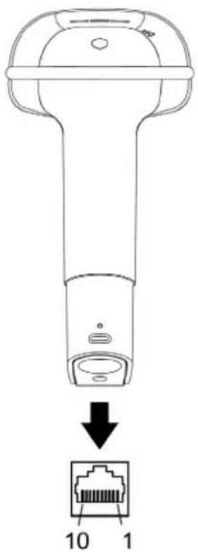
Figure 20.
| MS1690-47 or MS1691-47, Keyboard Wedge & Stand-Alone Keyboard | |
| Pin | Function |
| 1 | Ground |
| 2 RS232 Transmit Output | |
| 3 RS232 Receive Input | |
| 4 | PC Data |
| 5 | PC Clock |
| 6 | KB Clock |
| 7 | PC +5V |
| 8 | KB Data |
| 9 | +5VDC |
| 10 | Shield Ground |
| MS1690-11, RS485▲ | |
| Pin | Function |
| 1 | Ground |
| 2 RS232 Transmit Output | |
| 3 RS232 Receive Input | |
| 4 | RTS Output |
| 5 | CTS Input |
| 6 | Reserved |
| 7 | IBM B-Transmit |
| 8 IBM A+Receive | |
| 9 | +5VDC |
| 10 | Shield Ground |
▲ Applicable for IBM ® Host applications.
Scanner Pinout Connections
| MS1690-38, Low Speed USB | |
| Pin | Function |
| 1 | Ground |
| 2 RS232 Transmit Output | |
| 3 RS232 Receive Input | |
| 4 | RTS Output |
| 5 | CTS Input |
| 6 | USB D+ |
| 7 | V USB |
| 8 | USB D- |
| 9 | +5VDC |
| 10 | Shield Ground |
| MS1690-40, Full Speed USB | |
| Pin | Function |
| 1 | Ground |
| 2 RS232 Transmit Output | |
| 3 RS232 Receive Input | |
| 4 | RTS Output |
| 5 | CTS Input |
| 6 | USB D+ |
| 7 | V USB |
| 8 | USB D- |
| 9 | +5VDC |
| 10 | Shield Ground |
| MS1690-106 or MS1691-106,RS485 /Full Speed USB | |
| Pin | Function |
| 1 | Ground |
| 2 RS232 Transmit Output | |
| 3 RS232 Receive Input | |
| 4 | IBM A+ |
| 5 | IBM B- |
| 6 | USB D+ |
| 7 | V USB |
| 8 | USB D- |
| 9 | +5VDC |
| 10 | Shield Ground |

Figure 21.
▲ Applicable for IBM ® Host applications.
Cable Connector Configurations (Host End)
| “Standard” PowerLink Cable53-53000-3-FR Coiled |  | |
| Pin | Function |   9-Pin D-Type Connector 9-Pin D-Type Connector |
| 1 | Shield Ground | |
| 2 | RS232 Transmit Output | |
| 3 | RS232 Receive Input | |
| 4 | DTR Input/Light Pen Source | |
| 5 | Power/Signal Ground | |
| 6 | Reserved | |
| 7 | CTS Input | |
| 8 | RTS Output | |
| 9 | +5VDC | |
| Stand Alone Keyboard PowerLink Cable 53-53020-3 |  | |
| Pin | Function |  6-Pin Male Mini-DIN Connector 6-Pin Male Mini-DIN Connector |
| 1 | PC Data | |
| 2 | NC | |
| 3 | Power Ground | |
| 4 +5VDC PC Power to KB | ||
| 5 | PC Clock | |
| 6 | NC | |
| USB Power/Communication Cable53-53213-N-3-FR, 53-53214-N-3-FR or53-53235-N-3-FR |  | ||
| Pin | Function |  |  |
| 1 | PC +5V/V_USB | ||
| 2 | D- | ||
| 3 | D+ | ||
| 4 | Ground | USB Type ALocking with Power | USBNon-Locking |
| Shield | Shield | ||
Cable Connector Configurations (Host End)
| Keyboard Wedge PowerLink Cable53-53002-3 Coiled |  | |
| Pin | Function |  5-Pin DIN, Female 5-Pin DIN, Female |
| 1 | Keyboard Clock | |
| 2 | Keyboard Data | |
| 3 | No Connect | |
| 4 | Power Ground | |
| 5 | +5 VDC | |
| Pin | Function |  6-Pin DIN, Male 6-Pin DIN, Male |
| 1 | PC Data | |
| 2 | No Connect | |
| 3 | Power Ground | |
| 4 | +5 VDC | |
| 5 | PC Clock | |
| 6 | No Connect | |
Metrologic will supply an adapter cable with a 5-pin DIN male connector on one end and a 6-pin mini DIN female connector on the other. According to the termination required, connect the appropriate end of the adapter cable to the PowerLink cable, leaving the necessary termination exposed for connecting to the keyboard and the keyboard port on the PC.
| Keyboard Wedge Adapter Cable |  | |
| Pin | Function |  5-Pin DIN, Male 5-Pin DIN, Male |
| 1 | PC Clock | |
| 2 | PC Data | |
| 3 | No Connect | |
| 4 | Power Ground | |
| 5 | +5 VDC | |
| Pin | Function |  6-pin Mini DIN, Female 6-pin Mini DIN, Female |
| 1 | Keyboard Data | |
| 2 | No Connect | |
| 3 | Power Ground | |
| 4 | +5 VDC | |
| 5 | Keyboard Clock | |
| 6 | No Connect | |
The MS1690 Focus ® series scanners are manufactured by Metrologic at its Suzhou, China. The MS1690 series scanners have a five (5) year limited warranty from the date of manufacture. Metrologic warrants and represents that all MS1690 series scanners are free of all defects in material, workmanship and design, and have been produced and labeled in compliance with all applicable U.S. Federal, state and local laws, regulations and ordinances pertaining to their production and labeling.
This warranty is limited to repair, replacement of product or refund of product price at the sole discretion of Metrologic. Faulty equipment must be returned to one of the following Metrologic repair facilities: Blackwood, New Jersey, USA; Madrid, Spain; or Suzhou, China. To do this, contact the appropriate Metrologic Customer Service/Repair Department to obtain a Returned Material Authorization (RMA) number.
In the event that it is determined the equipment failure is covered under this warranty, Metrologic shall, at its sole option, repair the Product or replace the Product with a functionally equivalent unit and return such repaired or replaced Product without charge for service or return freight, whether distributor, dealer/reseller, or retail consumer, or refund an amount equal to the original purchase price.
This limited warranty does not extend to any Product which, in the sole judgment of Metrologic, has been subjected to abuse, misuse, neglect, improper installation, or accident, nor any damage due to use or misuse produced from integration of the Product into any mechanical, electrical or computer system. The warranty is void if: (i) the case of Product is opened by anyone other than Metrologic's repair department or authorized repair centers; or (ii) any software is installed on the Product other than a software program approved by Metrologic.
THIS LIMITED WARRANTY, EXCEPT AS TO TITLE, IS IN LIEU OF ALL OTHER WARRANTIES OR GUARANTEES, EITHER EXPRESS OR IMPLIED, AND SPECIFICALLY EXCLUDES, WITHOUT LIMITATION, WARRANTIES OF MERCHANTABILITY AND FITNESS FOR A PARTICULAR PURPOSE UNDER THE UNIFORM COMMERCIAL CODE, OR ARISING OUT OF CUSTOM OR CONDUCT. THE RIGHTS AND REMEDIES PROVIDED HEREIN ARE EXCLUSIVE AND IN LIEU OF ANY OTHER RIGHTS OR REMEDIES. IN NO EVENT SHALL METROLOGIC BE LIABLE FOR ANY INDIRECT OR CONSEQUENTIAL DAMAGES, INCIDENTAL DAMAGES, DAMAGES TO PERSON OR PROPERTY, OR EFFECT ON BUSINESS OR PROPERTY, OR OTHER DAMAGES OR EXPENSES DUE DIRECTLY OR INDIRECTLY TO THE PRODUCT, EXCEPT AS STATED IN THIS WARRANTY. IN NO EVENT SHALL ANY LIABILITY OF METROLOGIC EXCEED THE ACTUAL AMOUNT PAID TO METROLOGIC FOR THE PRODUCT. METROLOGIC RESERVES THE RIGHT TO MAKE ANY CHANGES TO THE PRODUCT DESCRIBED HEREIN.
CORPORATE HEADQUARTERS, NORTH AMERICA
Metrologic Instruments, Inc.
90 Coles Rd. C/Alfonso Gomez, 38-40, 1D
Blackwood, NJ 08012-4683 28037 Madrid
Customer Service Department Tel: +34 913 751 249
Tel: 1-800-ID-METRO Fax: +34 913 270 437
Fax: 856-228-6673
Email: info@metrologic.com
METROLOGIC EUROPEAN REPAIR CENTER (MERC)
Metrologic Eria Ibérica, SL
MTLGAUTO ID INSTRUMENTS (SHANGHAI) CO., LTD Suzhou Sales Office
BLK A, Room# 03/03-04
No.5 Xinghan Street, Xinsu Industrial Square
China-Singapore Suahou Industrial Park, Suzhou, PRC
Tel: 86-512-67622550
Fax: 86-512-67622560
Email: info@cn.metrologic.com
Safety
ITE Equipment
IEC 60950-1, EN 60950-1
LED
Class 1 LED Product: IEC 60825-1:1993+A1+A2, EN 60825-1:1994+A1+A2

Caution
Use of controls or adjustments or performance of procedures other than those specified herein may result in hazardous radiation exposure. Under no circumstances should the customer attempt to service the LED scanner. Never attempt to look at the LED beam, even if the scanner appears to be nonfunctional. Never open the scanner in an attempt to look into the device. Doing so could result in hazardous radiation exposure. The use of optical instruments with the LED equipment will increase eye hazard.
Atención
NOTE: Immunity performance is not guaranteed for scanner cables greater than 3 meters in length when fully extended.
Changes or modifications not expressly approved by the party responsible for compliance could void the user's authority to operate the equipment.
Class A Devices
The following is applicable when the scanner cable is greater in length than 3 meters (9.8 feet) when fully extended:
This equipment has been tested and found to comply with limits for a Class A digital device, pursuant to part 15 of the FCC Rules. These limits are designed to provide reasonable protection against harmful interference when the equipment is operated in a commercial environment. This equipment generates, uses and can radiate radio frequency energy and, if not installed and used in accordance with the instruction manual, may cause harmful interference to radio communications. Operation of this equipment in a residential area is likely to cause harmful interference, in which case the user will be required to correct the interference at their own expense. Any unauthorized changes or modifications to this equipment could void the user's authority to operate this device.
This device complies with part 15 of the FCC Rules. Operation is subject to the following two conditions: (1) This device may not cause harmful interference, and (2) this device must accept any interference received, including interference that may cause undesired operation.
Notice
This Class A digital apparatus complies with Canadian ICES-003.
Remarque
This is a class A product. In a domestic environment this product may cause radio interference in which case the user may be required to take adequate measures.
Changes or modifications not expressly approved by the party responsible for compliance could void the user's authority to operate the equipment.
Standard Europeo
Attenzione
The following is applicable when the scanner cable is less than 3 meters (9.8 feet) in length when fully extended:
This device complies with Part 15 of the FCC Rules. Operation is subject to the following two conditions: (1) This device may not cause harmful interference, and (2) this device must accept any interference received, including interference that may cause undesired operation.
This equipment has been tested and found to comply with the limits for a Class B digital device, pursuant to Part 15 of the FCC rules. These limits are designed to provide reasonable protection against harmful interference in a residential installation. This equipment generates, uses and can radiate radio frequency energy and, if not installed and used in accordance with the instructions, may cause harmful interference to radio communications. However, there is no guarantee that interference will not occur in a particular installation. If this equipment does cause harmful interference to radio or television reception, which can be determined by turning the equipment off and on, the user is encouraged to try to correct the interference by one or more of the following measures:
- Reorient or relocate the receiving antenna
- Increase the separation between the equipment and receiver
- Connect the equipment into an outlet on a circuit different from that to which the receiver is connected
- Consult the dealer or an experienced radio/TV technician for help
Notice
This Class B digital apparatus complies with Canadian ICES-003.
Remarque
For patent information, please refer to www.honeywellaidc.com/patents.
A
AC 2,7-11,28
Accessories ......2
Adapter....2, 39
Aperture....4
Audible Indicator....17–18, 35
B
Bar Code ......23–26, 27, 34
Bar Code Element .....19, 20
Beep.... 17–18, 23–26, 27, 35
Blue LED ...... 4, 7–11, 17–18, 35
C
Cable....3
Keyboard Wedge .....8, 38–39
MVC....3
PowerLink . 2, 5, 7–11, 23–26, 35, 38–39
RS232....7, 38–39
RS485....10
Stand Alone Keyboard ...9, 38–39
USB 11,38–39
Caution....7–11, 41–42, 41
CE 6,7-11
Class 41
Communication Parameters ..30–33
Compliance .... 7–11, 40, 41–42, 41, 42, 43
Configuration ... 2, 23–26, 29, 34, 35
Connector Pinouts....36–37
Converter....11
Current 28
Customer Service....2, 3, 40
D
DC 2, 28, 36–37, 38–39
Decode....27
Default Parameters .....29, 30–33
Keyboard Wedge ......30–33
RS232....30-33
RS485....30-33
Stand Alone Keyboard......30–33
USB.... 30-33
E
EMC.... 28, 42, 43
EMI 42,43
Emissions.... 42, 43
F
Firmware.... 35
Flash ROM.... 35
H
Host 5,7-11
|
Immunity 42, 43
Indicator
Audible 4, 17–18, 27, 35
Failure 4, 17–18
Visual 4, 17–18, 27, 35
Interface.... 23–26, 27
Cable.... 7–11, 38–39
Keyboard Wedge. 1, 2, 8, 29, 30–33, 36–37
RS232.1,2,7,29,30-33,36-37
RS485 1, 3, 10, 29, 30–33, 36–37
Stand Alone Keyboard 1, 2, 9, 29, 30–33, 36–37
USB... 1, 3, 11, 29, 30–33, 36–37
IR 1, 15, 21, 22
K
Keyboard Country Type ...... 29
Keyboard Type.... 29
Keyboard Wedge 2
L
Labels 6
LED...... 7–11, 23–26, 27, 41–42
Blue 7–11, 17–18
White 7–11, 17–18
Yellow.... 7–11, 17–18
Light Levels 28
Light Source 27
M
Maintenance....6
MetroSelect 16, 29, 34
MetroSet2....35
Mode of Operation....15
MS1690 Depth of Field......19
MS1691 Depth of Field......20
N
Notices 41
P
Patent....44
PDF 19,20
Pinouts ......36–37, 38–39
Power 7–11, 28, 35
Power Supply ....5, 7–11
PowerLink......4
Presentation 15
Product Safety....41–42
Protocols ......29
R
Razz 17–18, 23–26
Repair....40
RMA 40
RS232 2
s
Safety 41
SELV 7–11
Service 40
Single Trigger 15
Specifications
Electrical.... 28
Environmental 28
Mechanical 27
Operational.... 27
Stand 3, 12–14, 15
Stand Alone Keyboard 2
Swiftdecoder ® 1
T
Tone.... 17–18
Alternate.... 16
Transformer 2,7–11,28
Trigger 4
Troubleshooting 23–26
U
UL 6,7-11
Upgrade 35
USB
Full Speed .... 1, 3, 11, 29, 30–33, 37, 38
Low Speed ... 1, 3, 11, 29, 30–33, 37, 38
V
Ventilation 28
Visual Indicator 17–18, 35
Voltage.... 28
W
Warranty 40
White LED...... 4, 7–11, 17–18, 35
Window 4,6
Y
Yellow LED 4,7-11,17-18
Metrologic Instruments, Inc.
90 Coles Rd. Blackwood, NJ 08012-4683 · Email: info@metrologic.com
CUSTOMER SERVICE TEL: 1-800-ID-METRO · Corporate Tel: 856-228-8100
Fax: 856-228-6673 (Sales) • 856-228-1879 (Marketing) • Fax: 856-228-0653 (Legal/Finance)
METROLOGIC - THE AMERICAS
USA
Metrologic USA - Headquarters
Tel: 1.856.537.6400
Fax: 1.856.537.6474
Email: info@us.metrologic.com
Mexico
Metrologic Mexico, S.A. DE C.V.
Tel: 55.5365.6247
Fax: 55.5362.2544
Email: info@mx.metrologic.com
South America
Tel: 52.55.11.5182.7273
Fax: 52.55.11.5182.7198
Email: info@sa.metrologic.com
South America
Metrologic South America
Tel: 1.239.642.1958
Fax: 1.239.642.1959
Email: info@sa.metrologic.com
OMNIPLANAR
USA
Tel: 856.374.5550
Fax: 856.374.5576
Email: info@omniplanar.com
NOVODISPLAY
USA
Tel: 856.537.6139
Fax: 856.537.6116
Email: info@NOVOdisplay.com
METROLOGIC - EMEA
Central Europe
Metrologic Instruments GmbH
Headquarters
Tel: 49-89-89019-0
Fax: 49-89-89019-200
Email: info@de.metrologic.com
France
Metrologic Eria France SA
Tel: +33 (0) 1 48.63.78.78
Fax: +33 (0) 1 48.63.24.94
Email: info@fr.metrologic.com
METROLOGIC - EMEA
Spain
Metrologic Eria Iberica, SL
Tel: +34 913 272 400
Fax: +34 913 273 829
Email: info@es.metrologic.com
Russia
Metrologic Instruments LLC
Tel: +7 (495) 737 7273
Fax: +7 (495) 737 7271
Email: info@ru.metrologic.com
Italy
Metrologic Instruments Italia
Tel: +39 0 57 6511978 or
+39 051 651 1978
Fax: +39 0 51 6521337
Email: info@it.metrologic.com
Poland
Metrologic Instruments
Poland
Tel: +48 (22) 545 04 30
Fax: +48 (22) 545 04 31
Email: info@pl.metrologic.com
United Kingdom
Metrologic Instruments
UK Limited
Tel: +44 (0) 1256 365900
Fax: +44 (0) 1256 365955
Email: info@uk.metrologic.com
METROLOGIC - APAC
Asia
Metrologic Asia (Pte) Ltd
Headquarters
Tel:(65)6842-7155
Fax:(65)6842-7166
Email: info@sg.metrologic.com
China
Suzhou Sales Office
Headquarters
Tel: 86-512-67622550
Fax: 86-512-67622560
Email: info@cn.metrologic.com
China
Beijing Sales Office
Tel/Fax: 86 10 82253472
Email: info@cn.metrologic.com
METROLOGIC - APAC
China
Chengdu Sales Office
Tel/Fax: 86 28 86200109
Email: info@cn.metrologic.com
China
Guangzhou Sales Office
Tel: 86-20-38823476
Fax: 86-20-38823477
Email: info@cn.metrologic.com
India
India Sales Office
Tel: +91 80 41256718
Fax: +91 80 41256719
Email: info@in.metrologic.com
Korea
Korea Sales Office
Tel: 82-2-6205-5379
Fax: 82-2-3444-3980
Email:
Scott.lee@kr.metrologic.com
Japan
Metrologic Japan Co., Ltd.
Tel: 81-3-3839-8511
Fax: 81-3-3839-8519
Email: info@jp.metrologic.com
Thailand
Metrologic Thailand
Tel: +662-610-3787
Fax: +662-610-3601
Email:
tawan.jandang@th.metrologic.com
China
Shanghai
Tel: 86-21-58356616
Fax: 86-21-58358873
Email: info@cn.metrologic.com
Austrialia
Metrologic Australia
Tel: 61 2 9652 2726
(international)
Tel: 02 9816 6470 (local)
Tel: 1 800 99 88 38 (Australia)
Email:
kmason@au.metrologic.com
July 2008
- METROLOGIC INSTRUMENTS, INC
- MS1690 FOCUS® SERIES
- AREA IMAGING BAR CODE SCANNER INSTALLATION AND USER'S GUIDE
- COPYRIGHT
- TRADEMARKS
- INTRODUCTION
- INSTALLING THE SCANNER TO THE HOST SYSTEM
- STAND KITS
- SCANNER OPERATION
- TABLE OF CONTENTS
- PRODUCT OVERVIEW
- THE POWERLINK CABLE
- CONNECTING
- DISCONNECTING
- LABELS
- MAINTENANCE
- RS232
- KEYBOARD WEDGE
- STAND ALONE KEYBOARD
- RS485
- INTEGRATED USB: FULL SPEED (- 40 OR - 106) LOW SPEED (- 38)
- STAND COMPONENTS, MLPN 46-00147
- HARD MOUNTING THE STAND (OPTIONAL)
- ASSEMBLING THE STAND
- TWO DEFAULT MODES OF OPERATION
- MULTI-TRIGGER, OUT OF STAND
- PRESENTATION, IN-STAND
- AUDIBLE INDICATORS
- ONE BEEP
- SHORT RAZZBERRY TONE
- LONG RAZZBERRY TONE
- THREE BEEPS - AT POWER UP
- THREE BEEPS - CONFIGURATION MODE
- VISUAL INDICATORS
- NO LEDS ARE ILLUMINATED
- STEADY YELLOW
- STEADY BLUE
- STEADY BLUE AND SINGLE WHITE FLASH
- STEADY WHITE
- ALTERNATING FLASHING OF BLUE AND WHITE
- FLASHING BLUE
- FAILURE MODES
- LONG RAZZBERRY TONE – DURING POWER UP
- SHORT RAZZBERRY TONE – DURING SCANNING
- MS1690 IR ACTIVATION RANGE
- MS1691 IR ACTIVATION RANGE
- KEYBOARD TYPE
- KEYBOARD COUNTRY TYPE
- BAR CODES
- METROSET2
- SERIAL CONFIGURATION
- SCANNER PINOUT CONNECTIONS
- CORPORATE HEADQUARTERS, NORTH AMERICA
- METROLOGIC EUROPEAN REPAIR CENTER (MERC)
- MTLGAUTO ID INSTRUMENTS (SHANGHAI) CO., LTD SUZHOU SALES OFFICE
- SAFETY
- ITE EQUIPMENT
- LED
- CAUTION
- ATENCIÓN
- CLASS A DEVICES
- NOTICE
- REMARQUE
- STANDARD EUROPEO
- A
- B
- C
- D
- E
- F
- H
- K
- L
- M
- N
- P
- R
- S
- T
- U
- V
- W
- Y
- METROLOGIC - THE AMERICAS
- OMNIPLANAR
- NOVODISPLAY
- METROLOGIC - EMEA
- METROLOGIC - APAC
Brand : HONEYWELL
Model : 53-53020-3
Category : Computer and Other Cables