USER MANUAL 126 Argus
All rights are reserved. No portion of this document may be reproduced, duplicated or distributed in any form (print, copies, microfilm or on any other media) without intec's written permission.
Version: 1.00
1 Introduction 7
2 Safety Instructions 11
3 Technical data 12
4 Operation 13
5 Menu Hierarchy 17
6 Start-Up 23
7 Setting the Type of Access 32
8 Copper Line Tests 33
9 Selecting the Access mode 34
9.1 Operation on a BRI, U-Interface or PRI access 34
9.1.1 TE-Simulation mode 34
9.1.2 NT-Simulation mode 34
9.1.3 Permanent switch circuit (leased line) 35
9.1.3.1 Telephony on leased lines 35
9.1.3.2 BERT on leased lines (permanent circuits) 36
9.1.3.3 Loopbox with a permanent circuit ....41
9.1.3.4 Time measurements on leased lines 42
9.1.3.5 Switching back from leased line mode 44
9.1.4 BRI/PRI Monitor 45
9.1.5 BRI/ PRI Recorder 50
9.1.5.1 Administration of the recorded data .....52
9.2 Operation on a POTS access 56
9.2.1 The ARGUS as a POTS terminal .....56
9.2.2 POTS monitor 57
10 Operation on an X.21 Access 58
10.1 Start BERT 59
10.1.1 Display the test results 60
10.1.2 Saving the test results in the ARGUS 61
10.2 BERT wait 62
11 Tests on an ISDN Access 63
11.1 Test the Supplementary Services ......63
11.1.1 Suppl.serv.test for the 1TR6 protocol ......63
11.1.2 Suppl.service interrogation in DSS1 64
11.1.3 Supplementary Services Tests – Error messages ......67
11.2 Service test 68
11.3 Bit error test 71
11.3.1 Start BERT 73
11.3.1.1 BERT - saving 77
11.3.1.2 Display the saved BERT results 78
11.3.2 BERT wait 79
11.3.3 B-channel loop 80
11.4 X.31 Test 81
11.4.1 Automatic X.31-Test 81
11.4.2 Manual X.31 Test 84
11.5 CF Interrogation 86
11.6 CF - Activation 88
11.7 CF - Delete 89
11.8 MSN Interrogation (only on a BRI with DSS1) 90
11.9 Traffic generator (only on a PRI access) 91
11.10 Time measurements 93
11.10.1 Connection set up time 93
11.10.2 Time measurement: B-channel delay 94
11.10.3 Time measurement: Interchannel delay 95
12 Connection 96
12.1 Setting up an ISDN connection 96
12.2 Clearing Down an ISDN Connection 102
12.3 Operation on a POTS Access 104
13 Test Manager 106
13.1 Starting Several Tests to Run Simultaneously 107
13.2 Switching Between Tests 110
13.3 Cancel All 110
14 Test Results 111
14.1 Start the automatic test 113
14.2 Display Results 117
14.3 Sending the Results of a Test to a PC 118
14.4 Deleting the results of a test 119
14.5 Sending the results of all of the tests to a PC 119
15 Level measuring 120
15.1 Level measuring on a BRI access 120
15.2 Voltage Measurement on a U-Interface Access 122
15.3 Level measuring on a POTS access 124
16 L1 status 125
16.1 The L1 Status of a BRI Access 125
16.2 The L1 Status of a PRI Access 126
17 Settings 129
17.1 PC/Trace 129
17.2 Settings: ISDN 130
17.3 Settings: BERT 136
17.4 Settings: POTS 138
17.5 Settings: X.31 profile 140
17.6 Settings: ARGUS settings 143
17.7 Saving Call Numbers 145
17.8 Reset 147
17.9 Load Configuration from PC 150
18 Accu Servicing 151
19 Testing Features via the Keypad 153
20 Connection to a PRI Network 154
20.1 Pin Assignment on the ARGUS 126 (BRI/E1) 154
21 Appendix 155
A) Acronyms ....155
B) CAUSE-Messages – DSS1 Protocol .....158
C) CAUSE-Messages - 1TR6 Protocol ....160
D) ARGUS Error Messages ....162
1 Introduction
The ARGUS 126 premium ISDN tester is a combi-tester which has not only the test functions needed to support the installation and maintenance of BRI-, 2Mbit / E1, X.21, PRI and U-interface accesses but also those needed for POTS accesses.
In particular, service technicians, who increasingly work on larger, networked telephone systems and switching systems, will quickly find the ARGUS 126 an indispensable tool. With its rechargeable batteries and internal charger, the ARGUS is exceptionally well suited for use in field service. The intuitive menu operation combines convenient cursor keys and softkeys with a multi-line backlit display.
Besides TE/NT simulation on BRI and PRI accesses, the ARGUS 126 also supports TE simulation on U interfaces (optional) and POTS as well as convenient BRI and PRI D-channel monitoring. The 16 megabytes of internal Flash memory enables the tester to record and save the monitoring data without requiring a connection to computer.
The Flash-ROM technology permits you to upgrade your ARGUS at any time by download software updates from a PC. Free software updates are available at www.argus.info.
If you use the ARGUS on a BRI or PRI interface in an ISDN system whose specifications deviate from the (DIN ETS 300 102) standard (e.g. some networked PBXs), you must take these manufacturer-specific modifications into account. In such cases, please contact the distributor of your ISDN PBX for assistance.
For the test of X.21 permanent circuits (leased lines), you can connect the ARGUS to the X.21 network.
As an option, a V5.x monitor is available for the ARGUS 126: This monitor can be used to record the V5.1 or V5.2 protocol, which can then be decoded in detail with the WINanalyse software.
The integrated USB interface supports the rapid transfer of data between the ARGUS and a PC or notebook.
The ARGUS Functions - Overview:
Protocol Recognition and B-Channel Test for ISDN Accesses
After you select the operation mode, the ARGUS will automatically determine the protocol supported by the access under test and will then test the availability of the B-channels.
Telephone connections
Can a telephone call be placed from this access to every other number and/or can this access receive a call?
Service tests
Does the tested access support connections with the most important services, such as, ISDN telephone service, Group 4 - Facsimile or datatransmission at 64 kbit/s etc.?
Additionally, three user-specific services can be saved in the ARGUS and tested on the access under test.
Bit error tests (BERT) for PRI/E1, BRI, U-interface accesses with evaluation in accordance with G.821 and G.826
Performs a BERT in an extended call to itself, via a loopbox or in end-to-end operation. The ARGUS will, if needed, handle the loopbox function itself.
The integrated MegaBERT extends the bit error test on E1/PRI accesses to a full 2 Mbit/s bandwidth. Any distribution of time slots (n x 64 kBit/s) may be used.
Supplementary Services
The ARGUS automatically tests the supplementary services made available by the exchange.
Leased Line Tests – tests permanent circuits with BERT and speech
NT simulation of a BRI or a PRI access
D-channel monitoring on BRI and PRI interfaces
All of the D-channel signals are captured and passed to the serial interface. When passively monitoring, the ARGUS does not affect Layer 1.
CF Interrogation
The ARGUS will check, whether a call diversion has been setup on the access under test. The ARGUS can setup or clear down call diversions in the exchange.
MSN interrogation (only on a BRI access)
On a P-MP access using the DSS1 protocol, the ARGUS will determine the MSNs of the access under test.
POTS (analog) Functionality
Tests CLIP and other Caller-ID services in accordance with ETS 300 659/778.
Monitoring an analog line (passive listening-in)
POTS - Voltage and Polarity Measurement
X.21 test
The ARGUS will perform a bit error test on the X.21 access in accordance with the ITU guidelines G.821 and G.826.
The Access Acceptance Report
When the ARGUS is linked to a PC via the USB (or optional serial) interface, it is, as an example, possible - with the aid of WINplus - to create and print a comprehensive test report on the PC.
Testing Features via the Keypad
Supports manual tests in the so-called keypad mode. If the network supports this feature, the user can send a command sequence and can then test service features in a dialog.
Should you have any further questions, please contact us:
2 Safety Instructions
The ARGUS may only be used with the included accessories. Usage of other accessories may lead to erroneous measurements and may even cause damage to the ARGUS and the connected installation. The ARGUS is only to be used in accordance with the instructions in this documentation. Any other usage may result in bodily injury and destruction of the ARGUS.
- To prevent electrical shocks or damage to the ARGUS, do not connect it to lines with voltages in excess of 100 V!
- Never attempt a measurement with the case open!
- The ARGUS is not watertight. Protect the ARGUS from exposure to water!
- Before replacing the rechargeable batteries (see page 16 Replacing the accumulators), disconnect all the test leads and switch the ARGUS off. Make certain that the polarity is correct when connecting the accumulators!
Return and environmentally acceptable disposal
ARGUS is not subject to the RoHS (EU Directive on the "Restriction of Hazardous Substances") guidelines. Since October 2005 in compliance with WEEE (EU Directive on Waste of Electrical and Electronic Equipment) 2002/96/EU and the German Electrical and Electronic Equipment Act (ElektroG - Elektro- und Elektronikgerätegesetz), we have begun
marking our testers with the following symbol ( ) (DIN EN 50419).
In other words, the ARGUS may not be disposed of in the household waste. Regarding the return of old equipment, please contact our Service department.
3 Technical data
Dimensions and Weight
Height 280 mm, width 84 mm, depth 50 mm and weight 350 gr (without batteries and protective cover)
Keypad
25 Keys
LCD display
LCD display with switchable background lighting, 64mm x 40mm, 128 x 64 pixels
Memory
512 KBytes of RAM
16 MBytes of Flash memory for recording and
storing of data from monitoring
1 RJ-45 for BRI, PRI
1 RJ-45 for POTS and U-interface
DSub25 for X.21
1 DC jack for an external power supply
USB-A jack USB Client interface
1 RJ-11 for the serial interface (optional)
2.5mm jack for headset
Temperature Ranges
Ambient-temperature: 0 °C to +50 °C
Operational limits temperature: -5 °C to +55 °C
Power Supply
4 NiMH AA accumulators or ARGUS plug-in power supply
4 Operation

Power key
- Switch the ARGUS ON
- To start up again after a power down
- To switch on the display backlighting
In battery mode to save power, the backlighting will switch off automatically after 5 seconds.
- To switch off the ARGUS (must be pressed somewhat longer) If it is turned off when the power supply is connected, the unit will begin to charge the accumulators. (s. page 151 Accu Servicing)

Confirmation key
- Open menu
- The ARGUS will return to the previous display.
- Start test
- Confirm entries

Return key
- The ARGUS will return to the previous display and ignore any entries made at this level, e.g. changes to the settings
- Cancel test
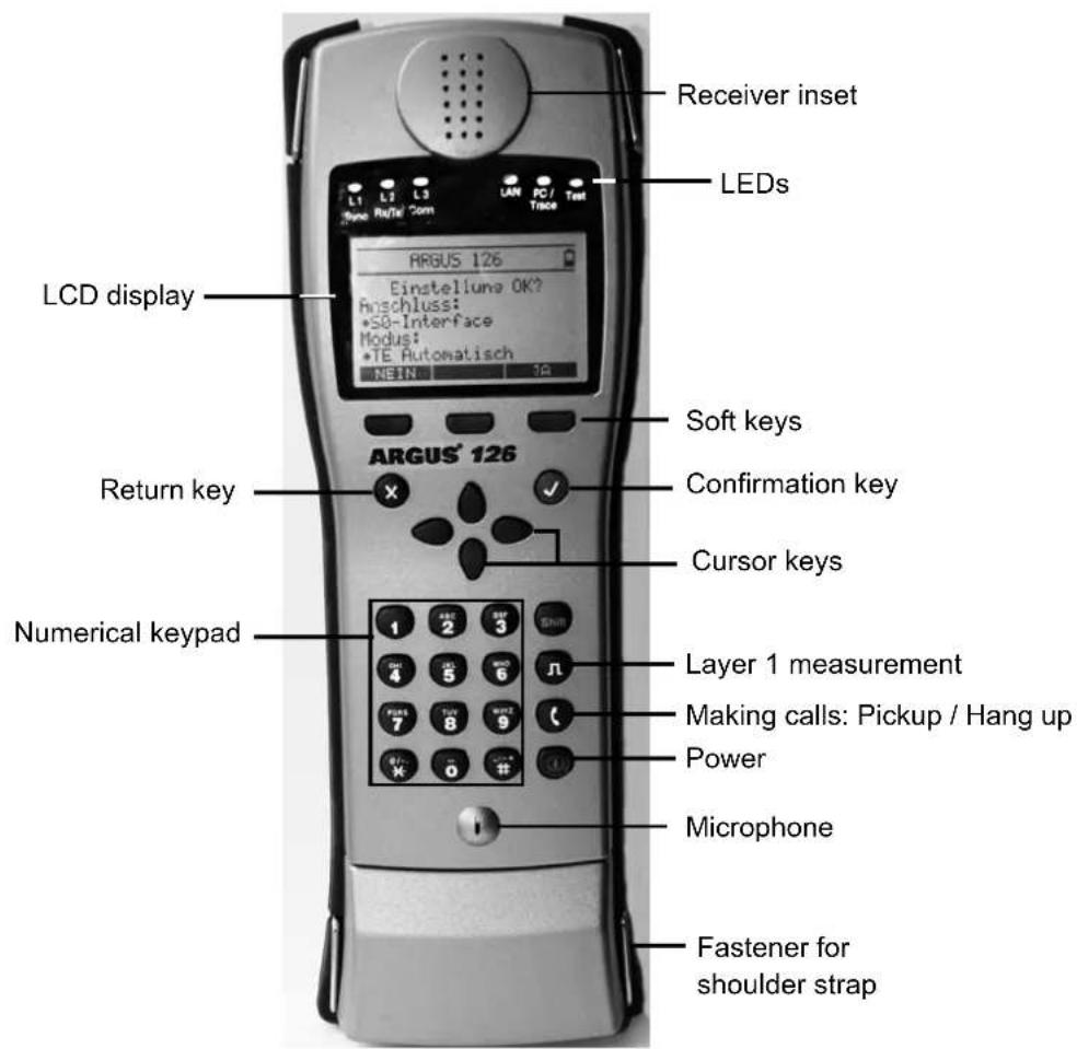
Cursor keys
- Scroll through the display lines (vertical cursor keys)
- Scroll through a display line (horizontal cursor keys)
- Select a menu
- Select a function or a test

Telephony
- Pickup or hang up
- Simplified overlap signalling: press the telephone key twice

Layer 1 measurement
- Start the Layer 1 measurement (level/voltage)
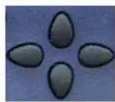
Numerical keypad
- Entry of the digits 0....9, letters and special characters
- Direct function call

Soft keys
- The function of the 3 softkeys varies with the situation. The current function of each softkey is shown in the bottom, highlighted line of the display.
The ARGUS is in largest part operated with the 4 cursor keys, the confirmation key √, the return key X and the three softkeys.
The current assignment of the three softkeys is shown in the lower line of the display.
On the following pages, only the softkey's meaning in the respective context is shown - enclosed in brackets < >, e.g. . The < √ > softkey serves the same function as the √ confirmation key and the < ↓ > softkey performs the same function as the corresponding arrow key on the ARGUS keypad.
Connectors at top
natural_image
Close-up of a metallic electronic device with labeled ports (PWR, SER, USB) and connectors (no readable text beyond labels)
PWR
Connection for the external plug-in power supply.
If the plug-in power supply is connected, the ARGUS will disconnect the accumulators and when it is switched off, the ARGUS will automatically recharge the accumulators (s. page 151 Accu Servicing).
SER. (cable optional)
Serial interface to connect a PC
USB
USB interface to connect a PC
Connector for a headset
Connections at bottom
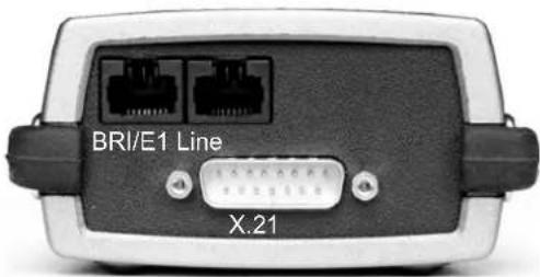
BRI / E1
Connection for a BRI network (pins 3, 4, 5 and 6)
Connection for a PRI network
(pins, see page 154).
Line
Connection for a POTS or U-interface network (pins 7 and 8)
X.21
Connection for the X.21 network
Replacing the accumulators
The compartment for the four accumulators (rechargeable batteries) is located on the back of the case. Unscrew the screws to remove the cover of the case and insert the accumulators in accordance with the polarity marking. Use only the accumulators included in the package. The current state of the charge will (if the ARGUS is not connected to a power supply) be displayed graphically.
In the LCD display, a battery symbol will begin to blink, when there is still approximately (depending on the mode of operation) 15 minutes reserve. During this period, it is possible that there may be audible interference and in rare cases even malfunctions (s. page 151 Accu Servicing).
Power Down

In accu operation, if the ARGUS is idle for 15 minutes, it will automatically switch to the power-down mode (power-down). The ARGUS will remain in power-down mode until the Power-Key is pressed again. Reasonably enough, the ARGUS will not enter power-down mode during a test (e.g. Loopbox) or when it is in Trace mode.
As an alternative, it is possible to operate the ARGUS using the included power supply. When the power supply is connected, the accumulators are automatically disconnected.
Regardless of the type of supply used, you should always operate the ARGUS with accumulators installed. This will ensure the uninterrupted operation of the real-time clock.
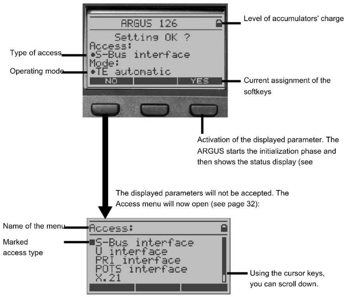
5 Menu Hierarchy
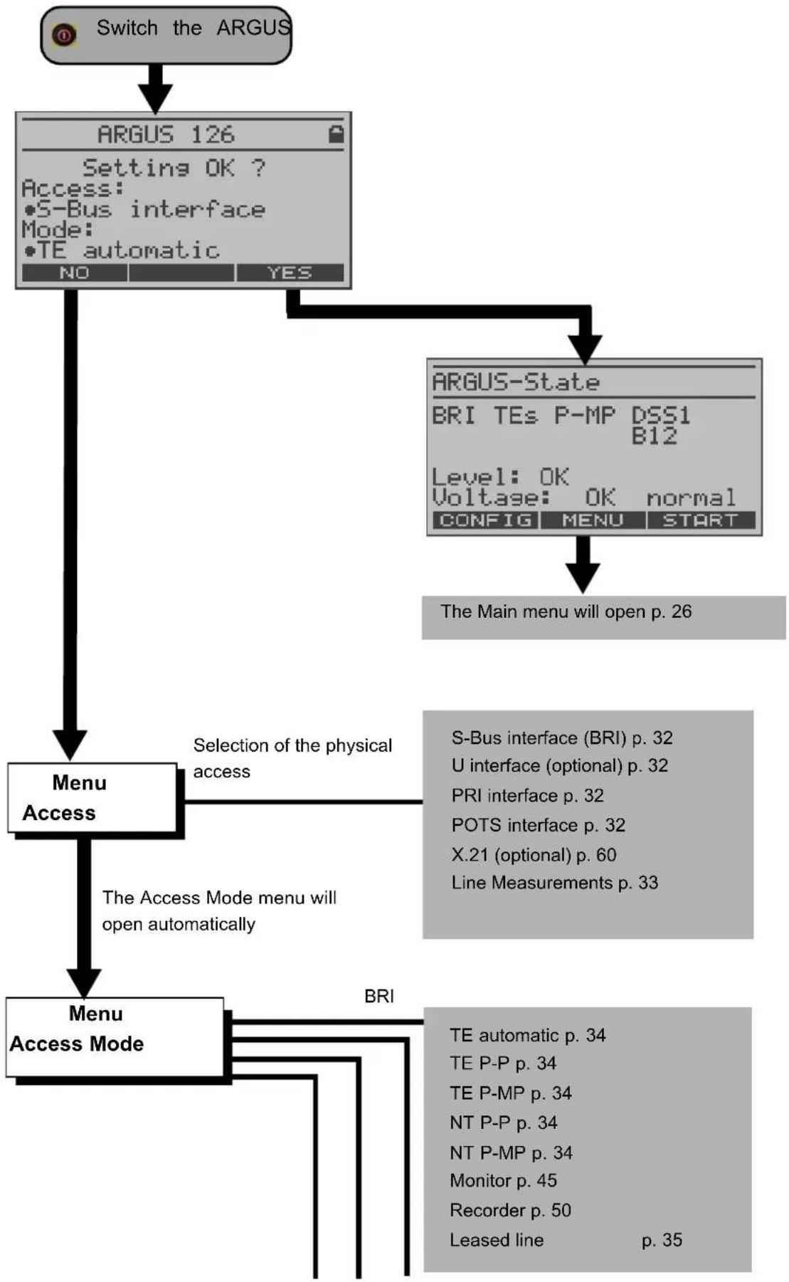
flowchart
graph TD
    A["Switch the ARGUS"] --> B["ARGUS 126\nSetting OK?\nAccess:\n•S-Bus interface\nMode:\n•TE automatic\nNO\YES"]
    B --> C["Menu Access"]
    C --> D{Selection of the physical access}
    D --> E["S-Bus interface (BRI) p. 32\nU interface (optional) p. 32\nPRI interface p. 32\nPOTS interface p. 32\nX.21 (optional) p. 60\nLine Measurements p. 33"]
    C --> F["Menu Access Mode"]
    F --> G{The Access Mode menu will open automatically}
    G --> H["BRI"]
    H --> I["TE automatic p. 34\nTE P-P p. 34\nTE P-MP p. 34\nNT P-P p. 34\nNT P-MP p. 34\nMonitor p. 45\nRecorder p. 50\nLeased line\np. 35"]
    B --> J["ARGUS-State\nBRI TEs P-MP DSS1\nB12\nLevel: OK\nVoltage: OK normal\nCONFIG MENU START\nThe Main menu will open p. 26"]
flowchart
graph TD
    A["U-interface"] --> B["TE automatic p. 34"]
    A --> C["TE P-P p. 34"]
    A --> D["TE P-MP p. 34"]
    A --> E["Leased line p. 35"]
    F["POTS"] --> G["POTS terminal p. 58"]
    F --> H["POTS monitor p. 59"]
    I["PRI"] --> J["TE P-P p. 34"]
    I --> K["NT P-P p. 34"]
    I --> L["Monitor p. 45"]
    I --> M["Recorder p. 50"]
    I --> N["Leased line p. 35"]
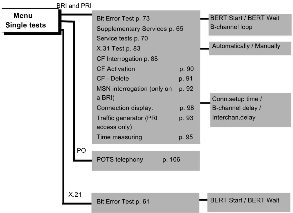
flowchart
graph TD
    A["Menu Single tests"] --> B["BRI and PRI"]
    B --> C["Bit Error Test p. 73"]
    B --> D["Supplementary Services p. 65"]
    B --> E["Service tests p. 70"]
    B --> F["X.31 Test p. 83"]
    B --> G["CF Interrogation p. 88"]
    B --> H["CF Activation p. 90"]
    B --> I["CF - Delete p. 91"]
    B --> J["MSN interrogation (only on a BRI)"]
    B --> K["Connection display p. 98"]
    B --> L["Traffic generator (PRI access only) p. 93"]
    B --> M["Time measuring p. 95"]
    A --> N["X.21"]
    N --> O["POTS telephony p. 106"]
    A --> P["X.21"]
    P --> Q["Bit Error Test p. 61"]
    Q --> R["BERT Start / BERT Wait"]
    R --> S["B-channel loop"]
    R --> T["Automatically / Manually"]
    R --> U["Conn.setup time / B-channel delay / Interchan.delay"]
    P --> V["BERT Start / BERT Wait"]
flowchart
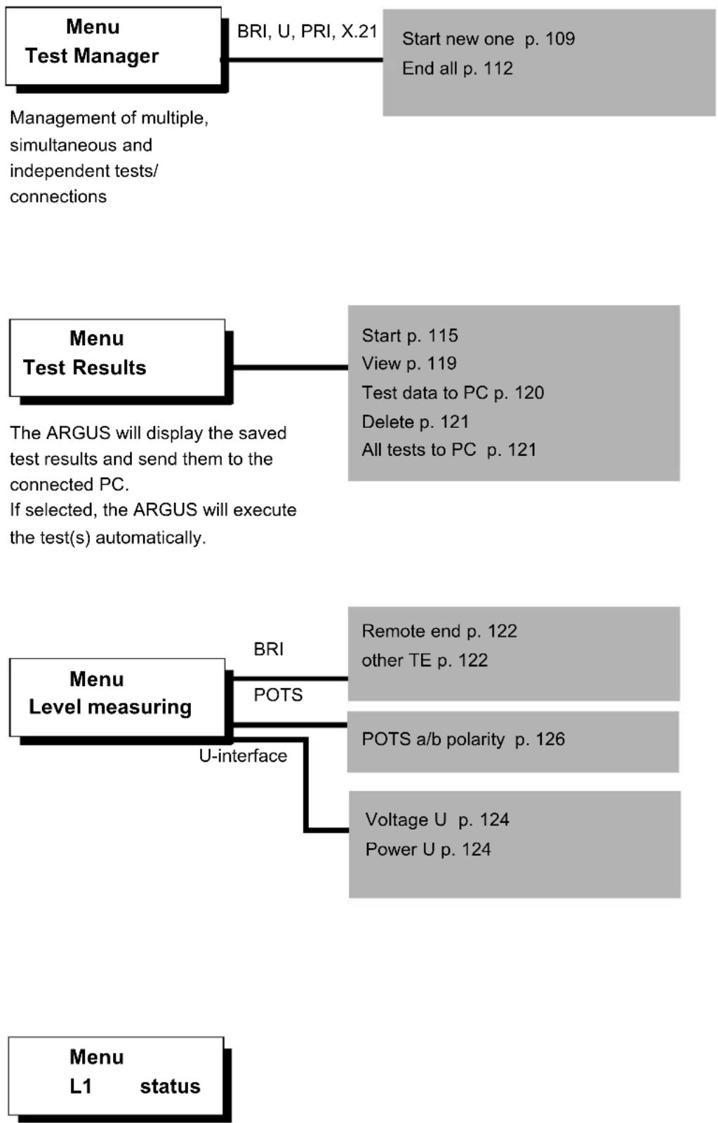
graph TD
    A["Menu Test Manager"] --> B["BRI, U, PRI, X.21"]
    B --> C["Start new one p. 109\nEnd all p. 112"]
    A --> D["Management of multiple, simultaneous and independent tests/connections"]
    E["Menu Test Results"] --> F["Start p. 115\nView p. 119\nTest data to PC p. 120\nDelete p. 121\nAll tests to PC p. 121"]
    E --> G["The ARGUS will display the saved test results and send them to the connected PC.\nIf selected, the ARGUS will execute the test(s) automatically."]]
    H["Menu Level measuring"] --> I["BRI"]
    H --> J["POTS"]
    H --> K["U-interface"]
    H --> L["Remote end p. 122\nother TE p. 122"]
    H --> M["POTS a/b polarity p. 126"]
    H --> N["Voltage U p. 124\nPower U p. 124"]
    O["Menu L1 status"] --> P
The ARGUS displays the current status of the Layer 1 on a BRI access (S. 127) and the Layer 1 parameter on a PRI access (S. 128).
Men Settings
The ARGUS can be configured to suit your special requirements.
The parameters are clearly organised in submenus (e.g. all the ISDN parameters are in the ISDN submenu)
The default (factory) settings can be restored by selecting "Reset".
Trace/Remote p. 131
ISDN p. 132
- L1 permanent?
- Protocol
- Alerting mode
- Clock mode
- BRI termination
- PRI termination
- PRI Monitor
- Sensitivity
- Setting the Sa5 bits
- Setting the Sa6 bits
- Setting the A-Bit
-CRC4 Mode
- Call parameter
- Services
- Call accepted
- Voice coding
- DTMF / Keypad
- Destination number
MSN
- CUG Index
- Keypad
BERT p. 138
- BERT time
- Bit patt. BRI/U
- Bit patt. PRI
- Bit patt. X.21
- Error level
- HRX value
POTS p. 140
- POTS dial
- POTS CLIP
- DTMF parameter
- FLASH time
X.31 profile p. 142
- Packet number
- TEI
- LCN
- Packet size
- Agree packet size
- Window size
- Agree window size
- Throughput
- Agree throughput
- User data
- CUG
- CUG Index
- D bit
- Facilities
- Profile name
ARGUS settings p. 145
- Menu language
- LCD contrast
- Date entry
- PC Interface
- V.24 Baud rate
- Alarm
- Software option
Numbers p. 147
Reset p. 149
PC - load
p. 152
configuration
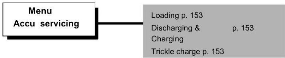
flowchart
graph LR
    A["Menu\nAccu servicing"] --> B["Loading p. 153\nDischarging & p. 153\nCharging\nTrickle charge p. 153"]
6 Start-Up
Using the included cable connect the ARGUS to the access to be tested and then switch the ARGUS on by pressing the TV.
The ARGUS displays the access and mode parameters which were last selected. In addition, the state of the accumulator charge is displayed if it is not connected to the plug-in power supply.

Press
Select a type of access
In the Access menu, use the cursor keys to select which type of physical access is to be tested.
The Access mode menu will open automatically (with two exceptions: X.21 and Copper line test). (see chap. 9 page 34).
Press

The ARGUS will set the type of access to the one marked with the ■. Afterwards, the ARGUS will start the initialisation phase.
Press

to return to the previous display without changing to the marked type of access
Press
Select the Access mode
Initialization phase:
- Initialization on a BRI or U-interface access (optional) or as a BRI NT simulator:
Next the ARGUS will setup Layer 1. While it is setting up Layer 1, the "L1 Sync" LED above the display will blink. If the ARGUS cannot setup Layer 1, it will display the message "No Net". When the ARGUS is operated on a U-interface access, it can take up to 2.5 minutes to activate Layer 1. As soon as Layer 1 is successfully setup, the "L1 Sync" LED will light continuously.
Once Layer 2 has been setup, the "L2 Rx/Tx" LED will light.

If both modes (P-P / P-MP) are found when Layer 2 on the D-channel is checked, the mode must be selected manually (see page 34).
If everything has been correctly detected, the ARGUS will display the type and mode of access found. Additionally, a qualitative assessment of the level will be displayed.
The ARGUS will automatically determine the protocol (in both TE and NT mode) or use the protocol set manually (see page 130 Protocol). On a bilingual access, the ARGUS will use the DSS1 protocol.
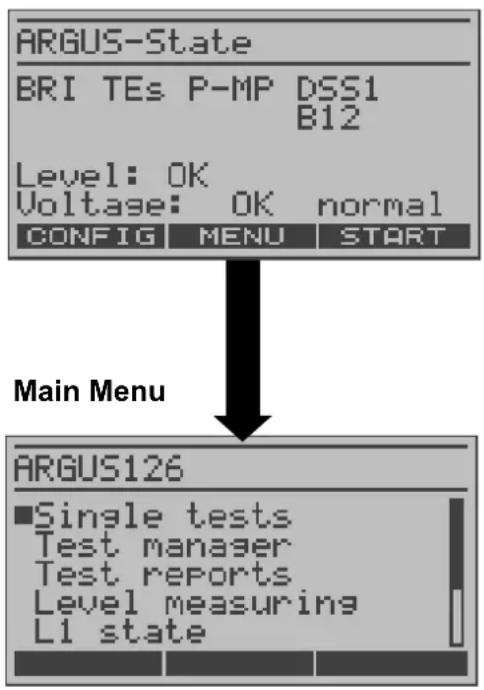
The “L3 Conn” LED will light after the ARGUS has setup Layer 3. At the same time the ARGUS will start the B-channel test. The results will be displayed on the ARGUS. If an error occurs in the B-channel test (e.g. access is not plugged-in), the ARGUS will - depending on the class of error - either repeat the initialization or show an error message (see page 162). The ARGUS will then idle in the Status display.
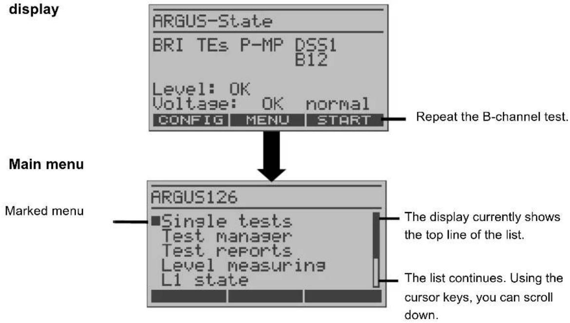
Example:
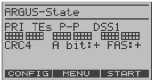
State display on a BRI access
flowchart
graph TD
    A["ARGUS-State"] --> B["BRI TEs P-MP DSS1 B12"]
    B --> C["Level: OK Voltage: OK normal CONFIG MENU START"]
    C --> D["Main Menu"]
    D --> E["ARGUS126"]
    E --> F["■Single tests Test manager Test reports Level measuring L1 state"]
The ARGUS displays the following:
- Access type (e.g. BRI)
- Access mode
NTs NT Simulation Slave Mode (see
NTm page 131)
TEs NT Simulation Master Mode
TEm TE Simulation Slave Mode
TE Simulation Master Mode
- Bus configuration (D-channel Layer 2 mode)
P-P Point-to-Point
P-MP Point-to-Multipoint
D-channel protocol (in the example, DSS1)
- The availability of the B-channels
B12 Both B-channels are available
B1- Only B-channel 1 is available
B-2 Only B-channel 2 is available
B-- No B-channel is available
- Level and voltage evaluation
OK normal Level/Voltage is OK
<< Level/Voltage is too low
Level/Voltage is too high
-- No level/voltage
OK Rev Emergency supply
Repeat the B-channel test.
The ARGUS will open the
ISDN Settings menu (see page 129).

If only one B-channel is available, this can have an impact on the service check and the testing of the supplementary services.
It must be mentioned again, that the ARGUS only determines the general bus status once when switched on or when the ARGUS first connected. On the other hand, the status of the protocol stacks for Layer 1, 2 and 3 will be continually monitored and displayed.
- Initialization on a PRI access
As soon as Layer 1 is successfully setup, the "L1 Sync" LED will light continuously. The ARGUS will automatically determine and display, whether or not the PRI access uses CRC4-monitoring. CRC4 monitoring can be switched on or off manually (see "CRC4 mode" page 133.).
The ARGUS will begin to automatically determine the access configuration. After Layer 2 is setup, the “L2 Rx/Tx” LED will also light.
The ARGUS will, regardless of the mode of operation (TE or NT mode), determine the D-channel protocol and attempt to setup Layer 3.
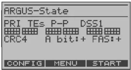
During this phase, the ARGUS displays the A bit of the remote side and the FAS. The protocol can only be determined when the A bit is not set (+). FAS (Frame Alignment Signal): Indicates whether the ARGUS could correctly synchronize with the incoming 2 Mbit data stream's alternating frame identification word or message word and the, perhaps present, CRC4-superframe structure.
Afterwards, the ARGUS will start the B-channel test. The ARGUS will check the availability of all 30 B-channels by placing an outgoing call on each B-channel one after the other. If the ARGUS can place a call on a B-channel, it will be assumed that the B-channel is available in both directions; the B-channel test cannot distinguish between alternating and exclusively "outgoing" B-channels. If the connection is rejected with Cause 44 (see Appendix B), the B-channel will be assumed to be only available for incoming calls. If the connection is rejected for any other cause, the B-channel will be identified as unavailable. In the case of a cause, which indicates that the B-channel is occupied, the connection will be tried up to two times and, if a connection can still not be setup, it will then be marked as unavailable.
An example:
State display on a PRI access
The ARGUS displays the following:
- Type of access, Access mode, Bus-configuration and D-channel protocol:
- The availability of the B-channels
Available B-channels: The light squares indicate the available B-channels and are ordered in two blocks of 15. The upper row of squares represent the B-channels that are available for outgoing connections, the lower row represents those that can be used for incoming calls.
left: B-channel 1
right: B-channel 30
In the example, all 30 B-channels are available and can be used for outgoing or alternating connections.
- CRC4-monitoring, A-Bit, FAS
B-channel test – example:
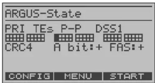
The ARGUS is in TE-Simulation Slave mode. B-channel 11 is not available.
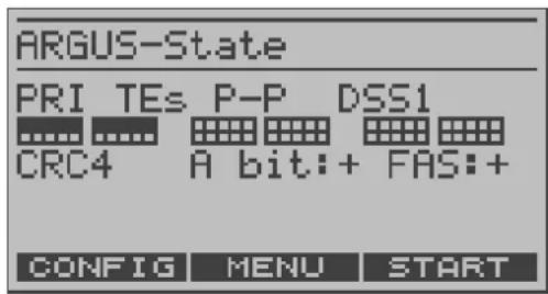
The first 10 B-channels are configured in the exchange as incoming channels only (seen from the viewpoint of the terminal), while B11-B30 can be used for outgoing or alternating connections.
If the ARGUS is not properly connected (e.g. incorrect cabling) or the network is not in order, the ARGUS will display "No Net".
- State display on a POTS access
The ARGUS will display the voltage when idle.
- State display on a U-interface access
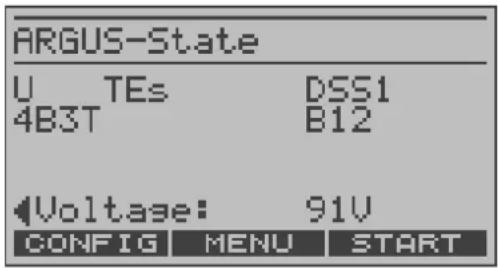
The ARGUS displays the Access mode, the D-channel protocol, U-interface variant, the availability of the B-channels and the voltage when idle.
The A RGUS Main Menu
For clarity, all of the available “actions” (commands) are logically organised in menus. All of the menus, which are available for the type of access under test, are listed in the Main menu.
ARGUS State
display
flowchart
graph TD
    A["Main menu"] --> B["Display"]
    B --> C["Main menu: ARGUS126"]
    C --> D["Main menu: Single tests\nTest manager\nTest reports\nLevel measuring\nL1 state"]
    C --> E["Main menu: The display currently shows the top line of the list."]
    C --> F["Main menu: The list continues. Using the cursor keys, you can scroll down."]
    B --> G["Display: ARGUS-State\nBRI TEs P-MP DSS1\nB12\nLevel: OK\nVoltage: OK normal\nCONFIG MENU START"]
    B --> H["Repeat the B-channel test."]


to have the ARGUS open the menu marked with the ■.
to return to the previous menu (in the example, the State display).
to select a menu.
PRI access BRI or U
POTS access X.21
Access
Single Tests Single Tests Single Tests Single Tests
Test Manager Test Manager ____ Test Manager
Test results Test results Test results Test results
____ Level measuring Level measuring ____
L1 state The L1 state (BRI
only)
Configuration Configuration Configuration Configuration
Access Access Access Access
Accu servicing Accu servicing
Accu servicing
Accu servicing
Using the numeric keys to start a test or function:
Using the numeric keys, you can start important ARGUS functions directly, regardless of the currently active menu level:
BRI and PRI accesses:
| Numeric key 2 | Start the service check | (see page 68) |
| Numeric key 3 | Start the suppl.serv.test | (see page 63) |
| Numeric key 4 | Start the AutoTest | (see page 113) |
| Numeric key 6 | Open the Test Manager | (see page 106) |
| Numeric key 7 | Open the Speed-Dialing Memory | (see page 145) |
| Numeric key 8 | Set to Trace mode | (see page 129) |
| Numeric key 9 | Start the bit error rate test (BERT) | (see page 73) |

If a function is called where the ARGUS expects the entry of a digit, pressing a number key will be interpreted as the expected input.
7 Setting the Type of Access
If the parameters displayed at power on are not accepted, the Access menu will open automatically. However, you can also open the Access menu at any time from the Main menu.
In the Access menu, the user must select the type of physical access to which the ARGUS is actually connected. When the ARGUS is restarted, the settings used last will be suggested as the default.
If you use the ARGUS on a BRI in an ISDN system, whose specifications deviate from the (DIN ETS 300 102) standard, such as those of some networked PBXs, you must take these manufacturer-specific modifications into account. In such cases, please contact the distributor of your ISDN PBX for assistance.
ARGUS State display
flowchart
graph TD
    A["ARGUS126"] --> B["■Single tests\nTest manager\nTest reports\nLevel measuring\nL1 state"]
    B --> C["■Access"]
    C --> D["✓"]
    D --> E["Access:"]
    E --> F["■S-Bus interface\nU interface\nPRI interface\nPOTS interface\nX.21"]
Open the Main menu
Using the the cursor keys select the Access menu
Using the cursor keys mark the desired type of access.

Press to confirm your selection The Access Mode menu will open automatically (see page 34).
The following applies for all displays:

The ARGUS will return to the previous display and ignore any changes to the settings.
In this case, the ARGUS would e.g. use the "old" access.
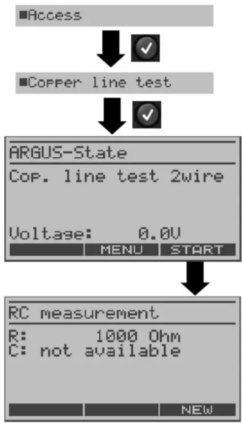
8 Copper Line Tests
Connect the ARGUS (Line jack) to the access to be tested and then switch the ARGUS on.

The line must be voltage-free (out of service) for this measurement!
flowchart
graph TD
    A["Access"] --> B["Copper line test"]
    B --> C["ARGUS-State\nCop. line test 2wire\nVoltage: 0.0V\nMENU START"]
    C --> D["RC measurement\nR: 1000 Ohm\nC: not available\nNEW"]
Open the Main menu and use the cursor keys to select the Access menu.
The ARGUS will first measure the resistance. If the resistance test shows that the line is open (infinite resistance), the ARGUS will measure the capacitance.
The ARGUS displays the measured resistance. The capacitance will not be displayed, since it is a closed line.
< NEW > To repeat the measurement
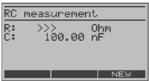
The ARGUS displays the capacitance. The line is open.
< NEW > To repeat the measurement
Resistance measurement:
200 Ohm to 100 kOhm
Precision 1%
Capacitance measurement:
1 nF to 1 μF
Precision 5%
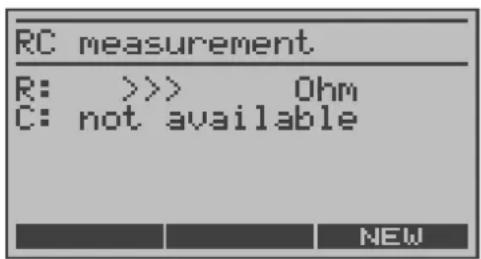
The resistance is out of the range of the ARGUS (e.g. greater than 100 kOhm).
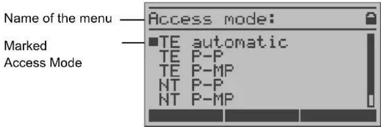
9 Selecting the Access mode
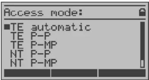
The Access mode menu is not selectable from the Main menu.
It opens automatically once the physical access is selected in the Access menu.
Using the cursor keys, select the desired Access mode.

Confirm the Access mode
The ARGUS will open the State display.
9.1 Operation on a BRI, U-Interface or PRI access
9.1.1 TE-Simulation mode
TE automatic
On a BRI or U-interface access, the ARGUS will automatically determined the D-channel Layer 2 mode (PP or P-MP). If the ARGUS determines that the access supports both modes, a configuration menu will open in which you can select the desired L2 mode.
TE P-P or TE P-MP
Afterwards, the access and the protocol stack will be initialized in accordance with the selected setting. When the ARGUS finds a PRI access, it will enter P-P mode.
9.1.2 NT-Simulation mode
NT P-P or NT P-MP
Afterwards, the access and the protocol stack will be initialized in accordance with the selected setting. When the ARGUS finds a PRI access, it will enter P-P mode.
9.1.3 Permanent switch circuit (leased line)
Besides dial-up connections to any subscriber, ISDN also supports the use of leased lines (circuits permanently switched to a specific remote location). These leased lines (permanent circuits) are available after setting up Layer 1, in other words after synchronizing both terminals by exchanging HDLC-frames. The location where the clock is generated can be selected (see page 131 Clock mode). As a quick test of a leased line, you can simply call the opposite end using a selected B-channel. However, for a more revealing test of a leased line, you should perform a bit error rate test.

Both ends of the leased line (permanent circuit) must use the same channel.
9.1.3.1 Telephony on leased lines
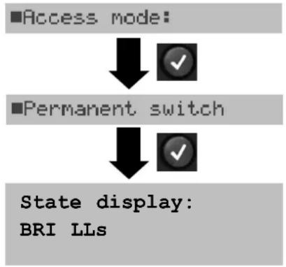
flowchart
graph TD
    A["■Access mode:"] --> B["✓"]
    C["■Permanent switch"] --> D["✓"]
    E["State display: BRI LLs"] --> F["✓"]
The ARGUS - Main menu
Display the LL(s) in the State display.

The ARGUS will open the B-channel selection.
The ARGUS displays the B-channels available. Use the vertical cursor keys to select a B-channel or enter the number of the B-channel on the keypad (first press ).

The ARGUS will setup the phone connection and display the B-channel used (e.g. B01) together with the duration of the leased line connection (permanent switch circuit) in hours:minutes:seconds.
Increases the volume.
or
< QUIET > sets it back to "Normal".
< TM > Start Test Manager (see page 106). Another connection can be setup.

Disconnect.
The ARGUS will open the State display.
Alternatively, in the Single tests menu, select Connection.
9.1.3.2 BERT on leased lines (permanent circuits)
On a BRI access:
■Single tests

■Bit error test

■BERT start

Select a channel
■B-channel (64k)

Enter the B-channel on the keypad.

A number of variations are possible in testing the permanent circuit with the bit error rate test.
In the simplest case, a B-channel loop will be set up at the remote end.
After selection of the channel to be tested (B-channel or D-channel), the ARGUS will send the test pattern, receive it back and evaluate it accordingly.
The displays and operation are, in largest part, similar to those of a BERT on a dial-up connection (see page 73) with the exception that you need not enter call numbers or select a service.
In the case of a BRI access in end-to-end mode (page 73 and page 79), it is also possible to run a BERT in the D-channel with HDLC-framing (setting: D-channel transp.).
Use the vertical cursor keys to select the B-channel.
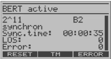
Start BERT
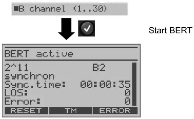
The ARGUS will display
- the bit pattern, B-channel used and the bitrate
- synchronicity of the bit pattern (synchron)
- Sync.time in h:min:sec (the period of time that the ARGUS has been synchronised)
- LOS counter
- the bit errors that have occurred
to insert artificial bit errors to test the reliability of the BERT.
The test time and bit error counter will be reset.
< TM > Start Test Manager (see page 106).
Once it is over, the ARGUS will display the results of the BERT (page 73). For information on saving the test results, see page 77.
On a PRI access:
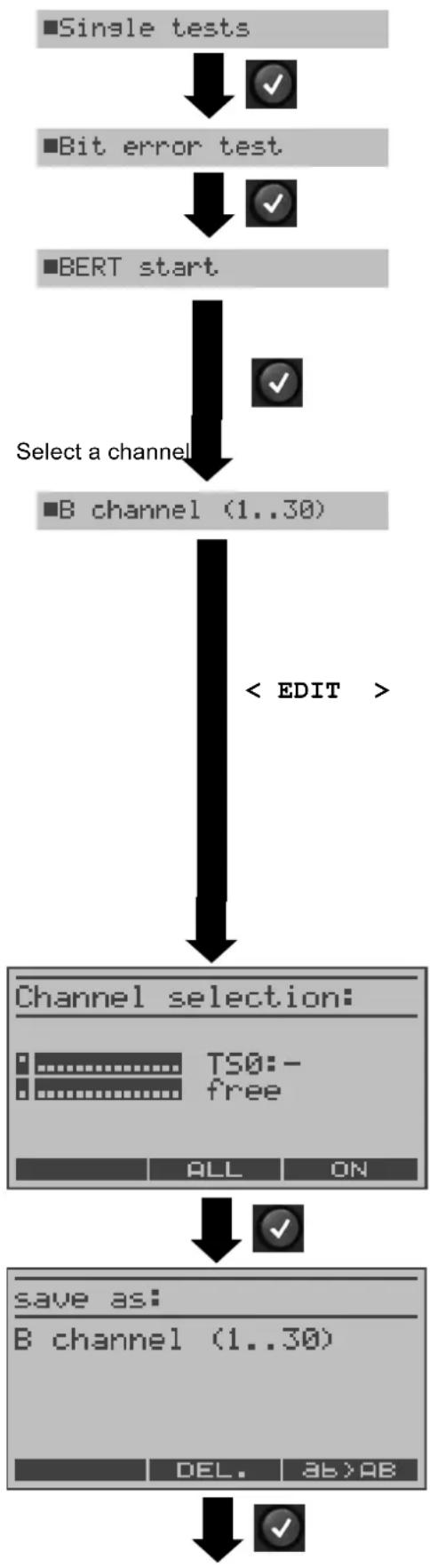
flowchart
graph TD
    A["■Single tests"] --> B["✓"]
    C["■Bit error test"] --> D["✓"]
    E["■BERT start"] --> F["✓"]
    G["Select a channel"] --> H["■B channel (1..30)"]
    H --> I["< EDIT >"]
    I --> J["Channel selection: TS0:- free ALL ON"]
    J --> K["✓"]
    L["save as: B channel (1..30) DEL. AB>AB"] --> M["✓"]
In the case of a PRI access in end-to-end mode (see "Bit error test" page 71 and page 79 "BERT wait"), a BERT can be run
- in the D-channel
- in all B-channels
- in all B-channels and in the D-channel (all framed)
- in selected B-channels
- in all channels and time slot 0 (all unframed)
The channel select mask will open.
In this mask you can chose from 3 predefined channel patterns:
- MegaBERT framed (default: all B-channels and the D-channel)
- MegaBERT unfr. (default: all B-channels, the D-channel and time slot 0)
- B-channel (1...30) (default: all B-channels) All three channel patterns can be changed as needed and saved under any name desired.

When the parameters (see page 147) are reset, the channel patterns are reset to their default settings.
To edit the channel pattern
For information regarding editing the channel pattern, see page 38.
If desired, enter the new name for the pattern to be stored under. When the right softkey is pressed it takes on a different meaning so that you can use the keypad to enter either letters or digits see page 141.
Store channel pattern
When “Selection” is chosen, the BERT will start as soon as a channel pattern is entered.
Set the channel pattern
Start BERT
Available B-channels ordered in two blocks of 15.
Editing the selected channel pattern:
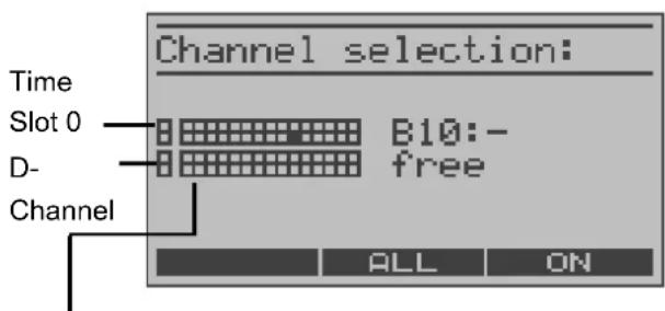
In the channel selection window, the light squares represent time slot 0 (upper display line left square), the D-channel (the left square on the lower display line) and the B-channels are assigned to the two blocks of 15 (upper display line B-channels 1 to 15, lower display line channels 16 to 30).
The selected channels are indicated in the upper row by black squares. The marked squares in the lower row indicate the current position of the cursor. The cursor is moved with the horizontal cursor keys:
The channels can also be marked with the cursor directly using the numerical keypad: If you enter the digits 08, the cursor will jump to B-channel 8. If you press the *, the cursor will move to time slot 0 while pressing the # will move the cursor to the D-channel.

Time slot 0 can only be selected, when all other channels (all B-channels and the D-channel) are selected (i.e. are free).
If the right softkey shows , pressing the softkey will select all B-channels and the D-channel (Mega BERT framed). When the right softkey shows , pressing the softkey will deselect the currently selected channels.
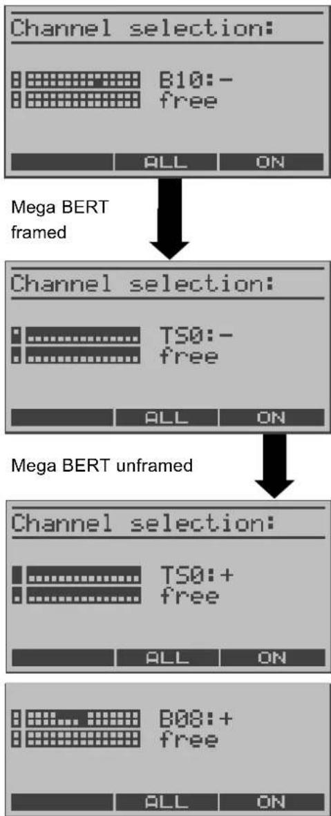
Channel selection examples
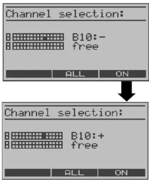
No B-channel has been selected; the cursor is sitting at B-channel 10 (marked square in the lower row). The ARGUS shows that the channel marked by the cursor has not yet been selected (display shows: "B10:-") and is free (display shows: "free").
Select the marked channel
B-channel 10 is selected (marked square in the upper row, display shows: B10: +)
flowchart
graph TD
    A["Channel selection: B10:- free"] --> B["Channel selection: TS0:- free"]
    B --> C["Channel selection: TS0:+ free"]
    C --> D["Channel selection: B08:+ free"]
    D --> E["Mega BERT framed"]
    E --> F["Mega BERT unframed"]
No B-channel has been selected; the cursor is sitting at B-channel 10.
Select all channels except time slot 0.
The cursor is sitting at time slot 0.
Select marked channel (time slot 0)
Time slot 0 is selected (TS0:+) and is still marked by the cursor (both squares are marked).
The channels 5 to 8 were individually marked with the cursor and selected with ; the cursor is at B-channel 8.
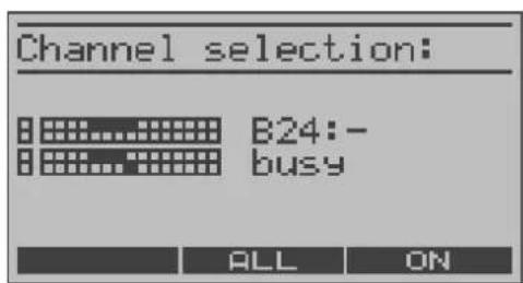
Channels 5 to 8 and 20 to 23 have been selected. The cursor is at channel 24. Channel 24 cannot be selected, since it is busy.
9.1.3.3 Loopbox with a permanent circuit
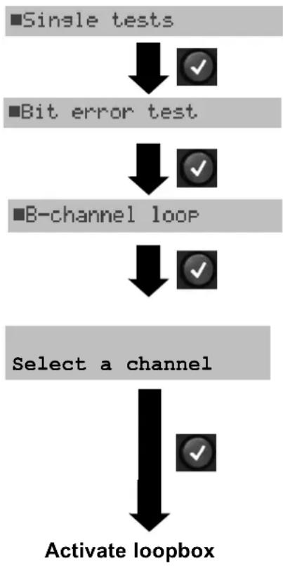
flowchart
graph TD
    A["■Single tests"] --> B["↓"]
    B --> C["✓"]
    D["■Bit error test"] --> E["↓"]
    E --> F["✓"]
    G["■B-channel loop"] --> H["↓"]
    H --> I["✓"]
    J["Select a channel"] --> K["↓"]
    K --> L["✓"]
    M["Activate loopbox"] --> N["↓"]
The ARGUS can be used as a loopbox on a leased line (permanent circuit).
Channel selection:
The ARGUS will loop either one B-channel (Channel selection: B-channel) or all B-channels and the D-channel (Channel selection: All framed).
In the case of a PRI access, you can also choose "All unframed" in the channel selection:
in which case the ARGUS will loop all B-channels, the D-channel and time slot 0.
The ARGUS will display the B-channel used and the amount of time (in h:min:sec) that the Loopbox has been active.

:to deactivate the loopbo)
9.1.3.4 Time measurements on leased lines
B-channel delay
The ARGUS places a call to a remote loopbox and measures the propagation delay for the data in the selected B-channel. The measurement (continuous measurement) must be terminated manually.
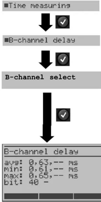
flowchart
graph TD
    A["■Time measuring"] --> B["✓"]
    C["B-channel delay"] --> D["✓"]
    E["B-channel select"] --> F["✓"]
    G["B-channel delay"] --> H["avg: 0,63,-- ms\nmin: 0,61,-- ms\nmax: 0,65,-- ms\nbit: 40 -"]
ARGUS in the Single tests menu
Enter the B-channel from the keypad (first press ) or use the cursor keys to scroll through all of the B-channels.
Perform measurement
The ARGUS displays the average (avg), the shortest (min) and the longest (max) B-channel delay as well as the average B-channel delay in bits (in multiples of the time required to send a bit at 64 kBit/s).
(The time for sending 1 bit at 64 kBit/s = approx. 15.26 μs.)
The measurement will be repeated in cycles (continuous measurement).
X : to terminate the measurement and display the results of the last measurement
When it is connected to a loopbox, if the ARGUS does not receive the data back within 13 seconds, it will display the message "No LOOP".
Interchannel delay
The ARGUS establishes two separate connections to a remote loopbox. The loopbox sends the respective B-channel data back on the same channel. The ARGUS measures the propagation delay for the data on each of the B-channels and determines the difference between the two propagation delays (interchannel delay). The measurement (continuous measurement) must be terminated manually.
flowchart
graph TD
    A["■Time measuring"] --> B["↓"]
    B --> C["■Interchannel delay"]
    C --> D["↓"]
    D --> E["B-channel select"]
    E --> F["↓"]
    F --> G["B-channel select"]
    G --> H["↓"]
    H --> I["Interchan. delay"]
    I --> J["avg: 0,00,-- ms"]
    I --> K["min: 0,00,-- ms"]
    I --> L["max: 0,00,-- ms"]
    I --> M["bit: 0 -"]
ARGUS in the Single tests menu
B-channel selection on a PRI access only:
Enter the first B-channel from the keypad (first press ) or use the cursor keys to scroll through all of the B-channels.
Enter the second B-channel from the keypad (first press ) or use the cursor keys to scroll through all of the B-channels.
Perform measurement
The ARGUS displays the average (avg), the shortest (min) and the longest (max) interchannel delay in msec. as well as the average interchannel delay in bits (multiples of the time required to send a bit at 64 kBit/s) - it takes 15.26 sec to send a bit at 64 kBit/s).
The measurement will be repeated in cycles (continuous measurement).

to terminate the measurement and display the results of the last measurement
When it is connected to a loopbox, if the ARGUS does not receive the data back within 13 seconds, it will display the message "No LOOP".
9.1.3.5 Switching back from leased line mode
flowchart
graph TD
    A["Access"] --> B["S-Bus interface"]
    B --> C["TE automatic"]
    C --> D(ARGUS State display]
    style A fill:#f9f,stroke:#333
    style B fill:#ccf,stroke:#333
    style C fill:#cfc,stroke:#333
    style D fill:#fcc,stroke:#333
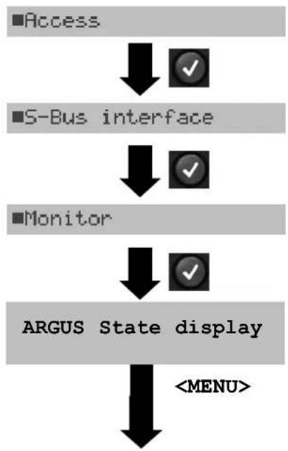
9.1.4 BRI/PRI Monitor
The ARGUS accepts all of the D-channel signals from the BRI or PRI access and sends these D-channel signals over the serial interface to a PC, which must be running ARGUS WINplus or WINAnalyse. The bus and Layer 1 are not influenced by the monitoring.
Monitoring a BRI access
flowchart
graph TD
    A["■Access"] --> B["✓"]
    C["S-Bus interface"] --> D["✓"]
    E["■Monitor"] --> F["✓"]
    G["ARGUS State display"] --> H["<START>"]
    H --> I["Monitoring"]
    I --> J["Durat. 0:01:55\nSignals: 21"]
    J --> K["LISTEN"]
    K --> L["Monitoring"]
    L --> M["Durat. 0:03:20\nSignals: 35"]
    M --> N["LOUD QIET TALK"]
flowchart
graph TD
    A["Monitorings\nDurat. 0:03:20\nSignals: 35"] --> B["N --> U\nB01 Speech\nfrom61 to :33\nTON:Unknown\nNP:unknown"]
    B --> C["Monitoring\nDurat. 0:03:20\nSignals: 35"]
    A --> D["LOUD QUIET TALK"]
    B --> E["SIGNAL"]
    C --> F["LOUD QUIET TALK"]
While monitoring, the ARGUS will search through all of the D-channels signals sent for a SETUP. If a SETUP is detected, the softkey will be displayed.
Display the call parameters of the last SETUP received.
The ARGUS displays the call direction (Net -> User), the channel used (in the example, B01), the service (in the example. Speech), the own number (in the example, 61) and the destination number (in the example, 33).
Display of other parameters:
- Sub-address (SUB),
- User-User-Info (UUI),
- DSP messages (if existent),
- Type of number (TON)
- Numbering plan (NP)
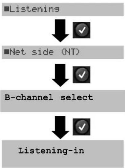
Listening-in when monitoring is not active
flowchart
graph TD
    A["Access"] --> B["S-Bus interface"]
    B --> C["Monitor"]
    C --> D["ARGUS State display"]
    D --> E["<MENU>"]
Monitoring is not active.
flowchart
graph TD
    A["■Listening"] --> B["↓"]
    B --> C["✓"]
    D["■Net side (NT)"] --> E["↓"]
    E --> F["✓"]
    G["B-channel select"] --> H["↓"]
    H --> I["✓"]
    J["Listening-in"] --> K["↓"]
    K --> L["✓"]
The ARGUS can passively listen-in on both the network-side and the terminal-side.
Enter the B-channel

to stop listening-in.
The ARGUS will return to the Main menu.
Monitoring a PRI access:
In the ISDN Configuration menu (see page 132), you can choose whether the ARGUS should monitor the D-channel or just Layer 1 (setting not supported in connection with the V5 option).
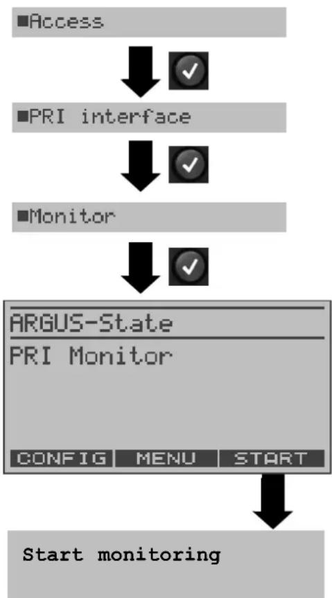
flowchart
graph TD
    A["Access"] --> B["PRI interface"]
    B --> C["Monitor"]
    C --> D["ARGUS-State"]
    D --> E["PRI Monitor"]
    E --> F["CONFIG MENU START"]
    F --> G["Start monitoring"]
As soon as a change occurs, the ARGUS will send a time-stamped report of the following alarms/states to the PC, which will evaluate them:
- Signal
- FAS
- CRC4det
- A bit
- AIS
The ARGUS will check the following values and counters every second and, in the event of a change, will pass them on the PC:
- Sa5-bit (Rx)
- Sa6-bit (Rx)
- E-bit
- Ecnt
- CRC Err.
- Cod.Err.
- Fram.Err.
For information on listening-in, see the BRI Monitor.
Display of the L1 Status in PRI Monitor mode
The L1 status function is only available in PRI Monitor mode. The Layer 1 alarms and messages are presented in several windows, which permit detailed statements regarding the state of the PRI access and the transmission line (For further information, see the CCITT/ITU guidelines G.703 and G.704).
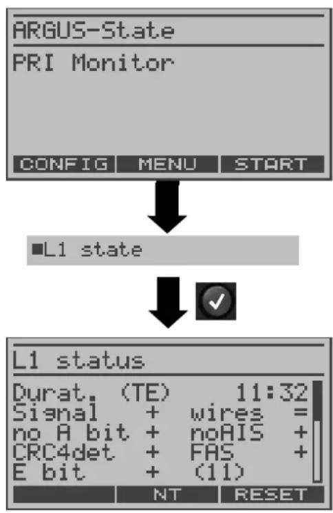
flowchart
graph TD
    A["ARGUS-State\nPRI Monitor"] --> B["L1 state"]
    B --> C["L1 status\nDurat. (TE) 11:32\nSignal + wires = no A bit + noAIS + CRC4det + FAS + E bit + (11)"]
    C --> D["NT RESET"]
The ARGUS is in PRI Monitor mode Monitoring is not active.
Display of the "TE-side parameters"
Use the cursor keys to scroll through the display.
Switch to "L1 status NT"; the "NT-side parameters" will be displayed
Reset the History function

Quit.
The ARGUS returns to the Main menu.
For a comprehensive explanation of the displayed information: see "The L1 Status of a PRI Access" page 126.
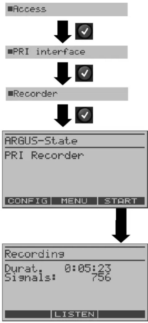
9.1.5 BRI/ PRI Recorder
In Recorder mode, the ARGUS passively monitors the connected BRI or PRI access.
The ARGUS records all of the D-channel signals sent in both directions without affecting the access or Layer 1.
Unlike in the Monitor mode, the recorded D-channel signals will be saved in the ARGUS's internal Flash memory and not sent to a PC. The storage is organized as a ring buffer, i.e. as soon as the Flash memory is full, the ARGUS will automatically overwrite the oldest data.
Operation on a PRI access:
flowchart
graph TD
    A["■Access"] --> B["✓"]
    C["■PRI interface"] --> D["✓"]
    E["■Recorder"] --> F["✓"]
    G["ARGUS-State"] --> H["PRI Recorder"]
    I["CONFIG MENU START"] --> J["↓"]
    K["Recording"] --> L["Durat. 0:05:23\nSignals: 756"]
    M["LISTEN"] --> N["↓"]
The ARGUS is in "PRI Recorder" mode. However, it is not yet recording!
Start recording (the PC/Trace LED flashes)
The display shows the recording time in h:min:sec and the number of recorded signals.
User) on this channel.

Stop recording. The Argus returns to "PRI Recorder" mode
For information on listening-in when not recording: see “Listening-in when monitoring is not active” page 46.
Parallel call display while recording
The ARGUS searches all of the D-channel signals sent for a SETUP. If a SETUP is detected, the softkey will be displayed.
Display the call parameters of the last SETUP received (see page 45).
On a PRI, the ARGUS saves a timestamped report of any changes in the following alarms/ states:
- Signal
- FAS
- CRC4det
- A bit
- AIS
The ARGUS will check the following values and counters every second and, in the event of a change, will save them:
- Sa5-Bit (Rx) / (Tx)
- Sa6-Bit (Rx) / (TX)
- E-bit
- Ecnt
- CRC Err.
- CRC rel.
- Cod.Err.
- Cod.rel
- Frm.Err.
For information on passively listening-in when the ARGUS is not recording, see page 46.
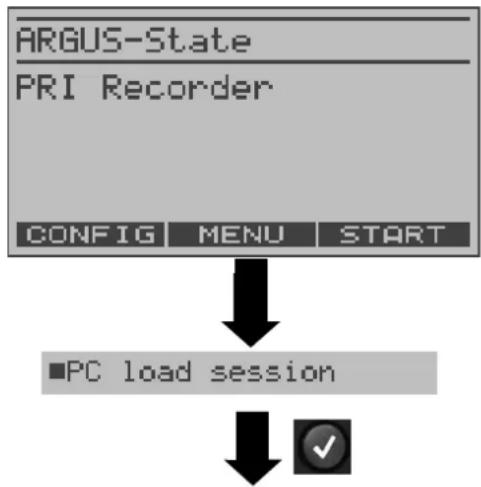
9.1.5.1 Administration of the recorded data
In the Recorder mode, several functions are available for administration of the data saved in the Flash memory:
- PC load all
- PC load session
- Internal decoding
- Reset Flash
- Info Flash
PC load all
With the "PC load all" function, the ARGUS will download all of the contents of the Flash memory via the serial interface to the PC, which must be running either WINplus or WINanalyse.
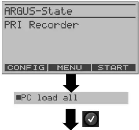
flowchart
graph TD
    A["ARGUS-State"] --> B["PRI Recorder"]
    B --> C["CONFIG MENU START"]
    C --> D["PC load all"]
    D --> E["✓"]
The ARGUS is in "PRI Recorder" mode. However, it is not yet recording!
Start charging the accumulators

The download is stopped.
The contents of the Flash memory will be downloaded to the PC.
Query whether the contents of the Flash memory should be deleted.
After the data has been successfully transferred to the PC, the Flash memory contents can be deleted.
< YES > Delete the contents of the Flash memory.
< NO > Do not delete the contents of the
or Flash memory. The ARGUS will

return to the Main menu.
PC load session
In the ARGUS, the storage in the internal Flash is organized as a ring buffer, which can hold the data from a series of several sessions (i.e. independent trace recordings). At the start of each session, the date and time will be written in the ring buffer.
The “PC load session” function transfers all of the data session-by-session to the PC on which either WINplus or WINanalyse must be running. The time and date that the session was started will be displayed in WINplus/WINanalyse.
flowchart
graph TD
    A["ARGUS-State"] --> B["PRI Recorder"]
    B --> C["CONFIG MENU START"]
    C --> D["PC load session"]
    D --> E["✓"]
The ARGUS is in "PRI Recorder" mode. However, it is not yet recording!
The loading of the individual sessions will start.
Session will be sent to the PC

The download is stopped.
Query whether another session should be sent to the PC.
Multiple sessions can be transferred to the PC one after the other.
< CONTI. > Send next session to the PC.
Query whether the contents of the Flash memory should be deleted.
After the data has been successfully transferred to the PC, the Flash memory contents can be deleted.
< YES > Delete the contents of the Flash memory.
< NO > Do not delete the contents of the
or Flash memory. The ARGUS will

return to the Main menu.
Internal decoding
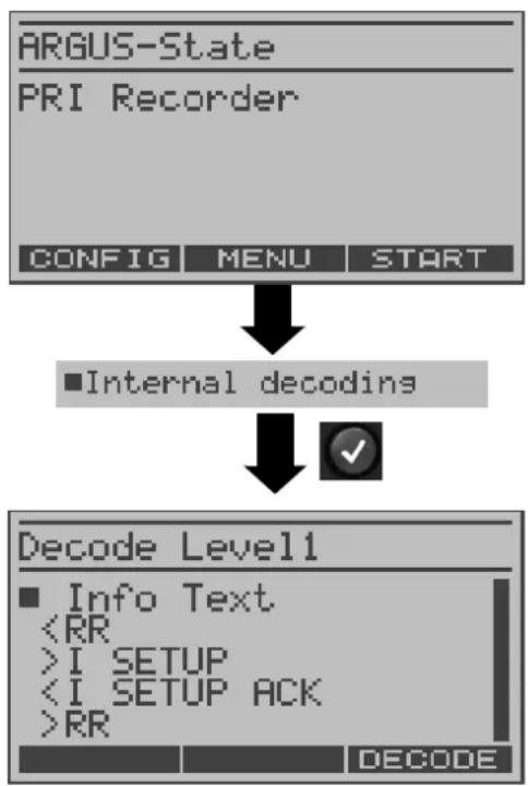
flowchart
graph TD
    A["ARGUS-State\nPRI Recorder"] --> B["CONFIG MENU START"]
    B --> C["■Internal decoding"]
    C --> D["✓"]
    E["Decode Level1\n■ Info Text\n<RR\n>I SETUP\n<I SETUP ACK\n>RR"] --> F["DECODE"]
The ARGUS will decode the D-channel data stored in the Flash memory.
The ARGUS is in "PRI Recorder" mode. However, it is not yet recording!
Display the signals sent to the network “<” and to the user “>”
Use the cursor keys to scroll through the display.
< DECODE > Display a detailed presentation (3 levels max.)
Info Flash
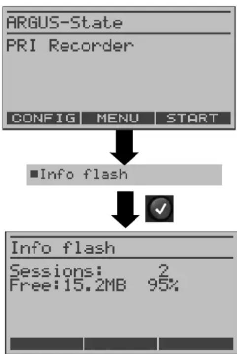
flowchart
graph TD
    A["ARGUS-State\nPRI Recorder"] --> B["CONFIG MENU START"]
    B --> C["Info flash"]
    C --> D["✓"]
    D --> E["Info flash\nSessions: 2\nFree:15.2MB 95%"]
Call up the status of the data in the Flash memory:
- The number of saved sessions
- Free memory in MB and in percent
The ARGUS is in "PRI Recorder" mode. However, it is not yet recording!
Display information on the status of the Flash memory.
The number of saved sessions (in the example 2) and the amount of free Flash memory in MB and percent.

Continue to the menu
Reset Flash
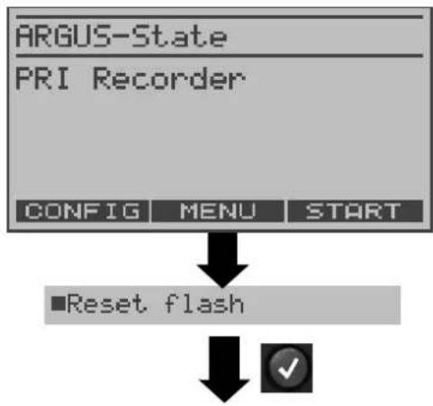
flowchart
graph TD
    A["ARGUS-State"] --> B["PRI Recorder"]
    B --> C["CONFIG MENU START"]
    C --> D["■Reset flash"]
    D --> E["✓"]
The Reset Flash function will delete the entire contents of the data Flash memory.
The ARGUS is in "PRI Recorder" mode. However, it is not yet recording!
Query whether the contents of the Flash memory should be deleted.
< YES > Delete the contents of the Flash memory.
The procedure can take several seconds. The ARGUS will show the progress of the procedure as the percentage deleted.
It is not possible to stop the process of deletion!
< NO > Continue to the menu
or The contents of the Flash memory will not be deleted.

9.1 Operation on a POTS access
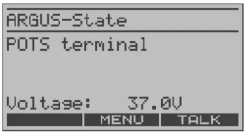
9.1.1 The ARGUS as a POTS terminal
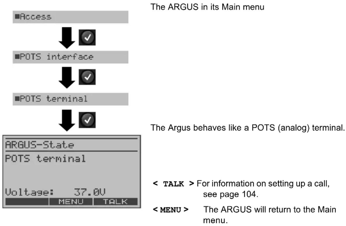
flowchart
graph TD
    A["Access"] --> B["POTS interface"]
    B --> C["POTS terminal"]
    C --> D["ARGUS-State"]
    D --> E["POTS terminal"]
    E --> F["Voltage: 37.0V"]
9.1.2 POTS monitor
Essentially, the POTS (analog) monitor provides a high impedance tap that does not influence the interface. You can listen to the line with the integrated handset without having the ARGUS send on or otherwise influence the interface.
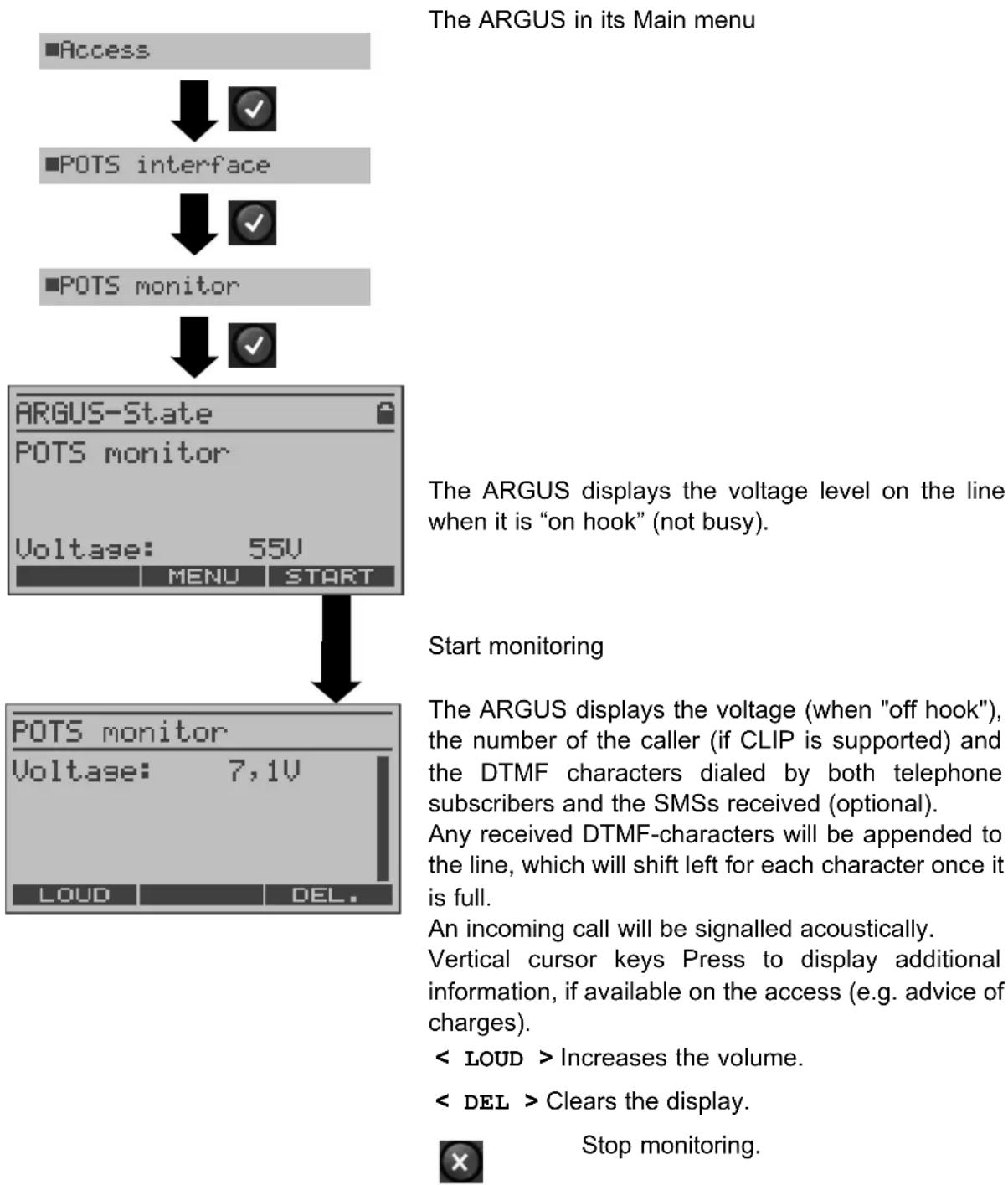
flowchart
graph TD
    A["■Access"] --> B["✓"]
    C["POTS interface"] --> D["✓"]
    E["POTS monitor"] --> F["✓"]
    G["ARGUS-State"] --> H["55V"]
    H --> I["MENU START"]
    I --> J["POTS monitor"]
    J --> K["7,1V"]
    K --> L["LOUD DEL."]
10 Operation on an X.21 Access
The ARGUS will perform a bit error test on the X.21 access in accordance with the ITU guidelines G.821 and G.826. Besides the measurement results, the ARGUS will also display the X.21 data rate.
Plug the adapter cable into X.21 jack to connect the ARGUS to the X.21 network.
flowchart
graph TD
    A["Access"] --> B["X.21"]
    B --> C["ARGUS-State"]
    C --> D["X.21-Test"]
    D --> E["MENU START"]
10.1 Start BERT
The ARGUS will detect the clock of the X.21 permanent circuit, calculate the data rate and then automatically search for the channels used. On these channels, the ARGUS will send the test pattern (see page 137 Bit pat. X.21) selected, receive it again and evaluate it in accordance with the ITU guidelines G.821 and G.826 (loopbox required at the remote end).
The following parameters are required for the BERT:
BERT time Test duration (default duration: 1 minute)
Error level If the bit error rate exceeds this limit, the ARGUS will display the test result NO. If the bit error rate is less than this limit, the ARGUS will display an OK (default setting = 10^-06 )
HRX value Hypothetical reference connection, see the ITU-T G.821
$$
(\text { default setting } = 15 \%)
$$
Bit pattern The bit pattern, which will be sent during the test (default setting =
$$
2 ^ {1 5} \text {-} 1)
$$
The parameters can be changed individually and saved (see page 136).
Start BERT
Display:
- Bit pattern (2^11) and X.21 data rate (e.g. 128 kBit)
- Synchronicity of the bit pattern (synchron)
- The amount of time that the ARGUS needed to synchronise (in h:min:sec)
- LOS counter
- The number of bit errors that have occurred
< RESET > Restart the bit error test; the counters (e.g. number of bit errors) will be reset.
Inject an "artificially generated" bit error
(in particular useful for end-to-end tests to demonstrate the reliability of the measurements).
< TM > For information on starting the Test Manager, see page 106.

Stop the BERT

When a bit error is detected, this will be signaled by a brief alarm (if the alarm is enabled); in the event that the synchronisation is lost, a constant alarm will sound.
The alarm bells can be switched off (see, page 144).
10.1.1 Display the test results
After the test is completed, the ARGUS will display the following test results:
The test results display:
The evaluation of the results depends on the error threshold (OK).
OK = the bit error rate is less than the error level set
OK = the bit error rate is greater than the error level set
Transferred data (e.g. 3752kb, K=1024 * bits),
k=1000* bits), Sync. time, No.LOS: LOS counter
no. of errors: The number of bit errors (e.g.10),
rel. errors: The bit error rate (e.g. 9.7E-07 = 9.7 · 10^-7 = 0.00000097 )
Display of other characteristic values (in accordance with ITU-T G.821)
All values are relative and given in percentages.
The ARGUS evaluates whether the test results satisfy the limits specified in the G.821 under consideration of the reference connection (HRX).
(The display will show either OK or NO).
Use the cursor keys to scroll through the results.

Continue to the BERT results
10.1.2 Saving the test results in the ARGUS
flowchart
graph TD
    A["BERT result\nOK\nsent data: 3752kb\nsync.time: 00:01:00\nNb. LOS : 0"] --> B["SAVE TM MORE"]
    B --> C["Save the result?"]
    C --> D["<YES>"]
    D --> E["save as:\n999999\nDEL. AB>AB"]
    E --> F["-Key"]
    F --> G["BERT start"]
Display the results
< YES > The ARGUS saves the results.
Use the keypad to enter the name under which the results should be saved
(Default: AMP_1, AMP_2.... or the call number of the access under test if the number has been entered into the speed-dialling memory (page 145))
When the right softkey is pressed it assumes a different meaning and thus influences the entries made from the keypad (letters or digits):
< 12>ab > entry of the digits 0 to 9 plus * and #
< ab>AB > entry of the lowercase characters and @, /, - and.
(e.g. to enter a "c" press the "2" on the keypad
three times)
12 > entry of the uppercase characters and @, /,- and.
To move the cursor right or left, use horizontal cursor keys.
< DEL > Delete the character before the cursor
The saved test results can be viewed in the test results menu (see page 117).
10.2 BERT wait
In this mode, the BERT will wait for the BERT at the remote end which is necessary for an end-to-end test: see “BERT wait” page 79.
11 Tests on an ISDN Access
11.1 Test the Supplementary Services
The ARGUS checks whether the access under test supports supplementary services in 1TR6 or DSS1 protocol.
11.1.1 Suppl.serv.test for the 1TR6 protocol
The ARGUS in its Main menu
flowchart
graph TD
    A["■Single tests"] --> B["✓"]
    C["■Supp.serv.test"] --> D["✓"]
    E["Sup.ser.req.1TR6"] --> F["Barrier + Call diversion-1 Call diversion-2 Access CUG - Taxation +"]
Start the test
The test results are displayed automatically:
- = suppl. service supported
- = suppl. service not supported
Use the cursor keys to scroll through the results

The ARGUS returns to the Single tests menu.
| Barrier Blocking enabled for outgoing calls |
| Call diversion 1 Call forwarding type 1 enabled (continuous) |
| Call diversion 2 Call forwarding type 2 enabled (case by case) |
| Access CUG Access belongs to a Closed Users Group |
| Taxation Advice of charge |
| Number ID Set up call number identifier - against malicious calls |
11.1.2 Suppl.service interrogation in DSS1
flowchart
graph TD
    A["Supp.serv.test"] --> B["Enter own number"]
    B --> C["Select service"]
    C --> D["Select a B-channel"]
    D --> E["Select test"]
    E --> F["Supp. Serv. test TP -"]
In the Single tests menu, use the cursor keys to select Service test.
Use the keypad to enter the "Own number" or select if from the speed-dialing memory (the number of the access under test) (see "Saving Call Numbers" page 145.). The ARGUS will test the availability of the supplementary service (in part by placing a call to itself).
Using the cursor keys, select the service which should be used for the supplementary services test.
Enter the B-channel on the keypad. By default, the channel last used will be suggested. If you enter an *, the ARGUS will choose any B-channel that is free.
Using the cursor keys, select which supplementary service should be verified to be supported by the access under test (e.g. the supplementary service TP).
Start the test
The ARGUS will display the results of the test once it is done:
- = suppl. service supported
- = suppl. service not supported
Use the cursor keys to scroll through the results

Close the results display.
The ARGUS will return to the previous display.
| Test Comments | |
| TP The ARGUS tests the TP (Terminal Portability) supplementary service by making a self call. |
| HOLD The ARGUS tests the HOLD supplementary service by making a self call. |
| CLIP (CLIP, CLIR, COLP, COLR) | In this test, the ARGUS checks, one after the other, whether the 4 supplementary services CLIP, CLIR, COLP and COLR are supported. To do so, the ARGUS will setup as many as three calls to itself.CLIP: Will the calling subscriber's number be displayed at the called subscriber?t = CLIP temporarily availablep = CLIP permanently availableCLIR: Will the display of the calling subscriber's number at the called subscriber be suppressed or is it possible to temporarily suppress the display?If the ARGUS displays an *, it is not possible to determine the availability of the service, since no CLIP has been set up.t = CLIR temporarily availablep = CLIR permanently availableCOLP: Will the call number of the subscriber who answered be displayed on the caller's phone?COLR: Will the display of the call number of the subscriber who answered be suppressed on the caller's phone or is it possible to temporarily suppress the display?If the ARGUS displays an *, it is not possible to determine the availability of the service, since no COLP has been set up.The suppl. services pairs CLIP and CLIR as well as COLP and COLR will be tested. If CLIR or COLR is set up permanently, it is not possible to make a clear assessment. |
| [CD736] |
| DDI Can a ca | aller directly dial in to an extension on the PBX access under test? |
| MSN Is the s | supplemental service MSN available? |
CF(CFU, CFB, CFNR) | In this test, the ARGUS will check whether the 3 supplementary services CFU, CFB and CFNR are supported.CFU: Can this access immediately forward an incoming call?CFB: Can this access forward an incoming call when it is busy; in other words does it support Call Forwarding Busy?CFNR: Can this access forward an incoming call when it is not answered?The CF test attempts to setup a call diversion to the call number that is in the memory location for “remote call number 1” (see “Saving Call Numbers” page 145). The CF test cannot be performed, if this location does not contain a valid call number to which it is possible to divert a call. |
| CW Does the | access under test support call waiting? |
| CCBS / CCBS-T | Will the access under test automatically recall a remote subscriber, if the number called was busy? |
| CCNR / CCNR-T | Will the access under test automatically recall a remote subscriber if the call was not answered? |
| MCID Does | the access tested allow identification of malicious callers (call tracing)? |
| 3pty Does the | access under test support a three-party conference call?For this test, you need the assistance of a remote subscriber, whose call number must be entered. |
| ECT Is an explicit call transfer supported by the access under test?For this test, you need the assistance of a remote subscriber, whose call number must be entered. |
| AOC The AR | GUS checks whether the charges can be sent to the access under test. The test uses a call to oneself to check both AOC-D (AOC during a call) and AOC-E (AOC at the end of a call). |
| SUB A call is | made to oneself and answered to check the transfer of the sub-address in both directions.Are sub-addresses supported on the access under test? |
| UUS Does the | access under test support the transfer of user data? |
| CUG The AR | GUS then uses a self call to check whether the access under test belongs to a closed user group. |
11.1.3 Supplementary Services Tests – Error messages
If an error occurs during the Supplementary Services Tests or if it is not possible to setup a call, the ARGUS will display the corresponding error code (e.g. 28).
Example: The error code 28 belongs to the error class "wrong or invalid number".
In the table below, you will find that this is an error from the network and that it reports that the call number was incomplete or in the wrong call number format (see “CAUSE-Messages – DSS1 Protocol” page 158.).
Distributing the error codes into error classes:
| Error class | Description Cause (from network) | Cause |
| 1 TR6 | DSS1 | ARGUS internal |
| A | no or another access _ | 201,204,205, | | 210,220 |
| B | wrong or invalid number | 53, 56 1,2,3, | 18,2122,28,88 | 152,161,162, |
| 199 |
| C | One or moreB-channels busy | 10,33,59 17,34,47 | | — |
| D | wrong service 3 49,57,58,63 | | 65,70,79 | — |
For further information about the error codes, see “ARGUS Error Messages” page 162, “CAUSE-Messages – DSS1 Protocol” page 158 and “CAUSE-Messages – 1TR6 Protocol” page 160.
11.2 Service test
The ARGUS checks, which of the following services are supported by the access under test:
Service Name displayed on the ARGUS
Language Language
Unrestricted Digital Information UDI 64kBit
3.1 kHz Audio 3.1kHz audio
7 kHz Audio 7 kHz audio
Unrestricted Digital Information with tones UDI-TA
/ display
Telephony Telephony ISDN
Facsimile Group 2/3 Fax G3
Facsimile Group 4 Class 1 Fax G4
Teletex service basis and mixed mode Mixed Mode
and facsimile service Group 4 Classes II
and III
Teletex Service basis mode Teletex
International inter working for Videotex Videotex
Telex Telex
OSI application according to X.200 OSI
7 kHz Telephony Telephony 7kHz
Video telephony, first connection Video telephony 1
Video telephony, second connection Video telephony 2
Three user-specific services (see, User-specified 1 to 3
page 134)
The test runs automatically.
For each service, the ARGUS will place a call to itself (to the access under test). However, the call will not be answered so no charges will be incurred.
flowchart
graph TD
    A["Service test"] --> B["Enter own number"]
    B --> C["Service test starts"]
ARGUS in the Single tests menu
Enter the number of the access under test

There are PBXs that use separate call numbers for incoming and outgoing calls. In this case, for the Service tests, you can enter a “remote” call number that does not match the “own” number that is stored in the ARGUS.
If the Service test should extend outside of the local exchange, it is possible to perform the Service test in an end-to-end mode.
In this case, you must enter the remote call number for a second terminal device. The ARGUS will then automatically check whether the remote terminal can accept the call under the various services – in other words, whether it is “compatible” with these services.
In the test results, the second part (second +, - or *) refers to the answer from the remote exchange.
Test results:
The ARGUS will display the results of the test once it is done.
Use the cursor keys to scroll through the results.
The ARGUS makes a distinction between outgoing calls (the first +, - or *) and incoming calls (the second +, - or *).
+ = Service supported
- = Service not supported
* A definite statement cannot be given, see the adjacent error code for the reason.
Interpreting the test results:
Display Explanation
++ The self call functions OK or the remote end can take the call for this service
+ - The call was sent successfully, however, it was rejected at the remote end due to a lack of authorization.
(Error class D in a B-channel message e.g. in a SETUP_ACK or CALL_SENT)
- An outgoing call with this service is not possible
(Error class D without a B-channel message)
+ * The call was sent successfully, the call back or call to the remote
end failed (e.g., remote end busy or no B-channel available for the call back).
* Wrong number, no B-channel available or other error
(Error class B, C or E without a B-channel message)
If the outgoing call is not successful, it is not possible to make a statement about an incoming call. Therefore, you will never see “- +” or “- *” on the display.
An example:
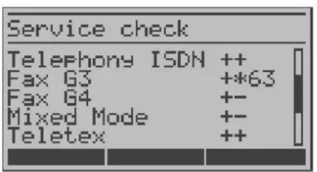
For outgoing, the Fax G3 service is OK. No statement is possible about incoming.
The error code 63 gives the coded cause of the error (see the table in the Appendix).
In this case, it is recommended that you have someone place a call to the access under test using this service.
The services Fax G4 and Mixed Mode are supported for outgoing calls.
The Teletex service is supported in both directions.
If an error of error class A occurs (see "Supplementary Services Tests – Error messages" page 67.) the Service test will be aborted. An error of any other error class will coded in decimal (in the example above 63), assigned to the respective service and then displayed.
11.3 Bit error test
The bit error rate test (BERT = Bit Error Rate Test) serves to check the transmission quality of the access circuit.
As a rule, the network operator will guarantee an average error rate of 1 × 10^7 , in other words in long-term operation 1 bit error in 10 million transmitted bits. A higher bit error rate will be especially noticeable in transmitting data.
The application program detects the errors in the data blocks transmitted and requests that the remote partner send them again, which reduces the effective throughput of the ISDN connection.
In the bit error test, the tester establishes an ISDN connection to a remote tester or places a call to itself, sends a standardized (quasi-) random number string and compares the received data with that which was sent. The individual bit errors are summed and depending on the test procedure and equipment evaluated in accordance with the ITU Guidelines G.821 and G.826.
During the test, the ARGUS counts the bit errors and after the test is done it calculates the bit error rate and other parameters in accordance with G.821 and G.826. Since the bit error test checks both B-channels in both directions at the same time, both B-channels are required.
As a rule, the quality of the network operator's access circuits is quite good. Therefore, no bit errors should occur in a 1-minute test.
However, if an error occurs, the test should be repeated with a measurement time of 15 minutes to achieve higher statistical precision. The access circuit is heavily distorted, if more than 10 bit errors occur within a test period of 15 minutes.
Contact the network operator or the supplier of the PBX equipment and ask them to test your access circuit.
The BERT can be performed in three different ways:
1. BERT in an extended call to oneself
A remote number is not needed, since the ISDN connection is set up to oneself. In this case, the ARGUS requires two B-channels for the test.
2. BERT with a loopbox
A loopbox (e.g., another member of the ARGUS family of testers at the remote end) is required. The test uses one B-channel.
3. BERT end-to-end
This test requires a waiting remote tester such as an ARGUS in the BERT wait mode (see page 79 BERT wait). A bit pattern is sent to this tester.
Independent of the received bit pattern, the remote tester uses the same algorithm to generate the bit-pattern that it sends back. Therefore, both directions are tested independently.
11.3.1 Start BERT
The following parameters are required for the BERT:
BERT time default duration = 1 minute
Error level If the bit error rate exceeds this limit, the ARGUS will display the test result NO. If the bit error rate is less than this limit, the ARGUS will display an OK (default setting = 10^-06 )
HRX value Hypothetical reference connection in %, see the ITU-T G.821 (default setting = 15 %)
Bit pattern Pattern which will be sent during the test
(default setting = 2^15-1 )
The parameters can be individually changed to suit and then saved (see page 136).
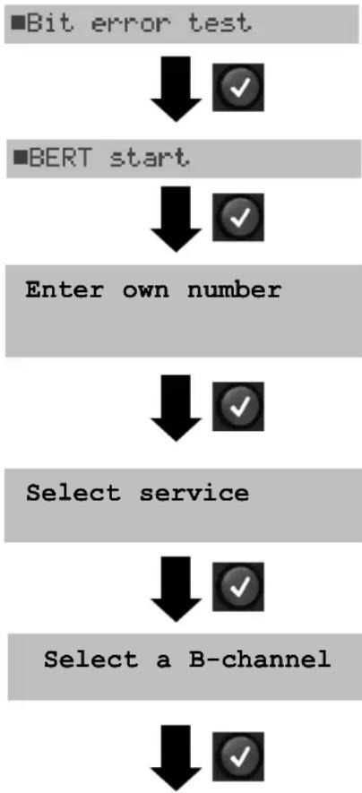
flowchart
graph TD
    A["Bit error test"] --> B["✓"]
    C["BERT start"] --> D["✓"]
    E["Enter own number"] --> F["✓"]
    G["Select service"] --> H["✓"]
    I["Select a B-channel"] --> J["✓"]
In the Main menu, select Bit error test.
Enter your Own number to perform the BERT in an extended call to oneself (two B-channels)
or
a remote number for a BERT to a loopbox (one B-channel) or end-to-end.
Using the cursor keys, select the service which should be used for the BERT.
Enter the B-channel on the keypad (first press ). If you enter an *, the ARGUS will choose any B-channel that is free.
Start BERT
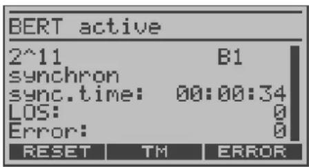
After the ARGUS has setup the connection and synchronized the send and receive directions, it will display the bit pattern, the B-channel used (e.g. B1), the synchronicity of the bit pattern (synchronous or asynchronous), the sync time in h:min:sec (time in which the ARGUS can sync to the bit pattern), the LOS counter and the number of bit errors that have occurred.
< ERROR > The ARGUS will generate an artificial bit error, which can be used to test the reliability of the measurement (in particular for end-to-end tests).
< TM > Call the Test Manager (see page 106)
< RESET > Restart the bit error test: The test time and number of bit errors will be reset.

Stop the BERT

When a bit error is detected, this will be signaled by a brief alarm; in the event that the synchronisation is lost, a constant alarm will sound (see page 144 Alarm bell).
After the test time is over, the ARGUS will display the cause and the location which initiated the disconnect. If the test ran normally, the ARGUS will display "Active clearing" on this line.
The test results display:
The evaluation of the results depends on the error threshold (OK).
Transferred data (K= 1024 * bits, k=1000*Bit),
sync.time
LOS counter
abs.err: The number of bit errors
rel. err: The bit error rate (e.g. 9.7E-07 = 9.7 · 10^-7 = 0.00000097 ),
Display of other characteristic values (in accordance with ITU-T G.821)
All values are relative and given in percentages. The ARGUS evaluates whether the test results satisfy the limits specified in the CCITT G.821 with consideration of the reference connection HRX (displaying OK or NO).
Use the cursor keys to scroll through the results.
< G0.826 > Display of the G.826 characteristic values

Display the prior results
Characteristic values in accordance with ITU-T G.821 / G.826
HRX Defines the hypothetical reference connection
EFS Error Free Seconds:
The number of seconds in which no error occurred.
ES821 Errored Seconds:
The number of seconds in which one or more errors occurred.
SES821 Severely Errored Seconds:
The number of seconds in which the bit error rate is >10^-3 .
In one second, 64,000 bits are transferred, thus BitERror= 10^-3 equates to 64 bit errors.
US Unavailable Seconds:
The number of all sequentially adjacent seconds (at least 9 sec) in which BER>10 ^-3 .
AS Available Seconds:
The number of all sequentially adjacent seconds (at least 9 sec) in which BER<10 ^-3 .
DM Degraded Minutes:
The number of minutes in which the bit error rate is >10^-6 .
In one minute, 3,840,000 bits are transferred, thus a BER = 10^-6
corresponds to 3.84 bit errors (3 errors = NO (no Degraded Minutes), 4
errors = OK (Degraded Minutes).
LOS Loss of Synchronisation:
Synchronization is lost at an error rate > or = 20% within a second. The absolute number of synchronization losses will be shown.
11.3.1.1 BERT - saving
The ARGUS can store the results of several BERTs. The ARGUS saves the results together with the date, time and call number of the access under test (if this number is entered as the "own" number in the speed-dialing memory) under the next free record number (see page 111).
If all of the records are used, the ARGUS will return to the Autom. Test dialog and request permission to overwrite the oldest test results.
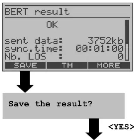
BERT - saving

Using the numeric keys enter the name under which the result should be saved (Default: AMP_1, AMP_2.... or the call number of the access under test if the number has been saved in the speed-dialing memory) When the right softkey is pressed it assumes a different meaning and thus influences the entries made from the keypad (letters or digits):
< 12>ab > entry of the digits 0 to 9 plus * and #
< ab>AB > entry of the lowercase characters and @, / , - and .
(e.g. to enter a "c" press the "2" on the keypad three times)
< AB>12 > entry of the uppercase characters and @, /,- and .
To move the cursor right or left, use the horizontal cursor keys.
Delete the character before the cursor

natural_image
Simple black vertical arrow pointing downward with a checkmark icon in the corner (no text or symbols)
■BERT start
11.3.1.2 Display the saved BERT results
The ARGUS in its Main menu
■Test reports

■ 1 0235190700
Use the cursor keys to select the record in which the BERT has been saved (in the example: record 1 with the access number 0235190700)

■Display result

ARGUS State display
The ARGUS will first display the status of the access under test.
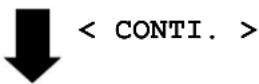
Display of the results
Display of the saved results (see page 117).
11.3.2 BERT wait
In BERT wait mode, the ARGUS will wait for the BERT at the remote end which is necessary for an end-to-end test.
ARGUS in the Single tests menu
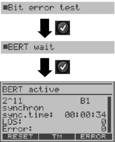
Activate "BERT wait"
The ARGUS first waits for a call and then sets up the connection. During the connection, the received bit pattern will be evaluated and an additional independent bit pattern will be sent.
< TM > Opens the Test Manager (page 106)
The ARGUS displays that will appear are the same as those in Kapitel 11.3.1 Start BERT.

Exit BERT wait mode
11.3.3 B-channel loop
B-channel loop mode is required in order to run a bit error test using a loopbox at the remote end as well as to test leased lines.
ARGUS - Single tests menu
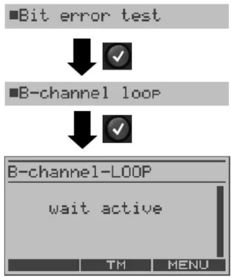
flowchart
graph TD
    A["Bit error test"] --> B["✓"]
    C["B-channel loop"] --> D["✓"]
    E["B-channel-LOOP"] --> F["wait active"]
    G["TM"] --> H["MENU"]
Activate the B-channel Loop
The ARGUS will wait for a call. Any incoming call (regardless of the service) will be taken immediately. The ARGUS will switch a loop back in the B-channel that is specified by the exchange and then send the recieved bit pattern back to the caller/sender.
