CM42 - Measuring device FLIR - Free user manual and instructions
Find the device manual for free CM42 FLIR in PDF.

User questions about CM42 FLIR
0 question about this device. Answer the ones you know or ask your own.
Ask a new question about this device
Download the instructions for your Measuring device in PDF format for free! Find your manual CM42 - FLIR and take your electronic device back in hand. On this page are published all the documents necessary for the use of your device. CM42 by FLIR.
USER MANUAL CM42 FLIR
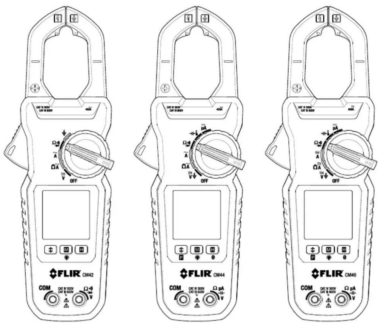
Models CM42, CM44, and CM46
1. DISCLAIMERS 4
1.1 Copyright 4
1.2 Quality Assurance 4
1.3 Documentaon 4
1.4 Disposal of Electronic Waste 4
2. SAFETY 5
3. INTRODUCTION 7
4. DESCRIPTION 8
4.1 Meter Parts 8
4.2 Funcon Switch Posions 9
4.3 Funcon Buons 10
4.4 Display Icons and Indicators 10
5. OPERATION 12
5.1 Powering the Meter 12
5.2 Intelligent Auto Power OFF (APO) feature 12
5.3 Auto Range 12
5.4 Out-of-range Warning 12
5.5 Voltage Measurements 13
5.6 Electric Field (EF) Detecon 14
5.7 Standard Current Clamp Measurements 15
5.8 Low Current Accu-Tip ^TM Clamp Measurements 17
5.9 DC A Current Test Lead Measurements (CM44 and CM46) 18
5.10 Resistance Measurements 19
5.11 Connuity Tests 19
5.12 Capacitance Measurements (CM44 and CM46) 20
5.13 Temperature Measurements (CM44 and CM46) 21
5.14 Diode Tests 22
5.15 Relave / DC Zero Modes (CM44 and CM46) 23
5.16 MIN/MAX/AVG Recording 23
5.17 VFD Mode (low pass Iter) 23
5.18 Display Hold Funcon 24
5.19 Display Backlighng 24
5.20 PEAK Mode (CM44 and CM46) 24
6. MAINTENANCE 25
6.1 Troubleshoong Tips 25
6.2 Accuracy and Calibraon 25
6.3 Cleaning and Storage 25
6.4 Baery Replacement 25
7. SPECIFICATIONS 26
7.1 General specicaons 26
7.2 Electrical specicaons 28
8. TECHNICAL SUPPORT 31
9. WARRANTY 32
1. Disclaimers
1.1 Copyright
© 2016, FLIR Systems, Inc., All rights reserved worldwide. No parts of the soware including source code may be reproduced, transmied, transcribed or translated into any language or computer language in any form or by any means, electronic, magnec, opcal, manual or otherwise, without the prior written permission of FLIR Systems.
The documentaon must not, in whole or part, be copied, photocopied, reproduced, translated or transmied to any electronic medium or machine readable form without prior consent, in wring, from FLIR Systems.
Names and marks appearing on the products herein are either registered trademarks or trademarks of FLIR Systems and/or its subsidiaries. All other trademarks, trade names or company names referenced herein are used for idencaon only and are the property of their respective owners.
1.2 Quality Assurance
The Quality Management System under which these products are developed and manufactured has been cered in accordance with the ISO 9001 standard.
FLIR Systems is commied to a policy of connuous development; therefore, we reserve the right to make changes and improvements on any of the products without prior noce.
1.3 Documentaon
To access the latest manuals and nocaons, go to the Download tab at: hp://support.ir.com. It only takes a few minutes to register online. In the download area you will also nd the latest releases of manuals for our other products, as well as manuals for our historical and obsolete products.
1.4 Disposal of Electronic Waste
As with most electronic products, this equipment must be disposed of in an environmentally friendly way, and in accordance with exisng regulaons for electronic waste.
Please contact your FLIR Systems representave for more details.
SAFETY NOTES
This user manual contains informaon and warnings that must be followed for operang the instrument safely and maintaining the instrument in a safe operang condion. If the instrument is used in a manner not specied by the manufacturer, the protecon provided by the instrument may be impaired.
The meter protecon rang, against the users, is double insulaon per UL/IEC/EN61010-1 Ed. 3.0, IEC/EN61010-2-033 Ed. 1.0, CAN/CSA C22.2 No. 61010-1 Ed. 3.0, IEC/EN61010-2-032 Ed. 3.0 & IEC/EN61010-031 Ed. 1.1: Measurement Category III 600V & Category IV 300V AC & DC.
BRIEF INFORMATION ABOUT MEASUREMENT CATEGORIES
Measurement Category IV is applicable to test and measuring circuits connected at the source of the building's low-voltage MAINS installaon. Examples are measurements on devices installed before the main fuse or circuit breaker in the building installaon.
Measurement Category III is applicable to test and measuring circuits connected to the distribuon part of the building's low-voltage MAINS installaon. Examples are measurements on distribuon boards (including secondary meters), circuit-breakers, wiring, including cables, bus-bars, juncon boxes, switches, socket-outlets in the xed installaon, and equipment for industrial use and some other equipment such as stationary motors with permanent conneccon to the xed installaon.
Measurement Category II is applicable to test and measuring circuits connected directly to ulizaon points (socket outlets and similar points) of the low-voltage MAINS installaon. Examples are measurements on MAINS CIRCUITS of household appliances, portable tools and similar equipment.
TERMS USED IN THIS MANUAL
WARNING Idenes condions and acons that could result in serious injury or even death to the user.
CAUTION Idenes condions and acons that could cause damage or malfuncon in the instrument.

WARNING STATEMENTS
To reduce the risk of re or electric shock, do not expose this product to rain or moisture. The meter is intended only for indoor use.
To avoid electrical shock hazard, observe the proper safety precautions when working with voltages above 60 VDC or 30 VAC rms. These voltage levels pose a potential shock hazard to the user. Before and aer hazardous voltage measurements, test the voltage function on a known source such as line voltage to determine proper meter functioning.
Keep hands/ngers behind the hand/nger barriers (of the meter and the test leads) during measurement. Inspect test leads, connectors, and probes for damaged insulaon or exposed metal
before using the instrument. If any defects are found, replace them immediately. Use only the test leads provided with the equipment (or UL Listed Probe Assemblies rated CAT III 600V or beer).
The accompanied test probe assembly meets UL/IEC/EN61010-031 Ed. 1.1 to the same meter rangs or beer. IEC 61010-031 requires exposed conducve test probe ps to be ≤ 4mm for CAT III & CAT IV rangs. Refer to the category markings on your probe assemblies as well as on the add-on accessories (detachable Caps or Alligator Clips, etc.), if any, for applicable rang changes.
This Clamp meter is designed to be clamped around or removed from un-insulated, hazardous live conductors. Nonetheless, individual protecve equipment must be used when hazardous live parts in the installaon, where the measurement is to be carried out, could be accessible.
Remove test leads from meter before taking clamp measurements.

CAUTION STATEMENTS
Disconnect the test leads from the test points before changing meter funcons.
Disconnect the test leads from the meter before taking clamp measurements.
Do not use the device for a procedure that it is not intended for. This can cause damage to the protecon built into the instrument.

UL lisng is not an indicaon or a vericaon of the accuracy of the meter
INTERNATIONAL ELECTRICAL SYMBOLS

Cauon! Refer to the explanaon in this Manual

Cauon! Risk of electric shock

Earth (Ground)

Double Insulaon or Reinforced insulaon

Fuse

AC (Alternang Current)

DC (Direct Current)

Applicaon around, and removal from, hazardous live conductors is permied
CENELEC DIRECTIVES
The instruments conform to CENELEC Low-voltage direcve 2014/35/EC, Electromagnec compatibility direcve 2014/30/EU and RoHS direcve 2011/65/EU.
Thank you for selecng the FLIR Auto Range, True RMS 400A Clamp Meter with Low Pass Filter and Accu-Tip ^TM low current measurement technology.
All meters in this series measure 400A AC, 600V AC/DC, Resistance, Connuity, Frequency, and Diode. Features include Non-Contact Voltage Detector, Data Hold, MIN/MAX/AVG, and display backlighng.
The CM44 and CM46 also oer Capacitance, Peak, A DC (test leads), Relave/DC Zero, and Thermocouple features.
The CM46 also provides DC, DC+ACV, and DC+DCA clamp measurements.
This device is shipped fully tested and calibrated and, with proper use, will provide years of reliable service.
Key Features:
All Models
- 6000-count digital backlit display
- 600V AC/DC test lead measurements
• Auto Range True RMS AC 400A AC clamp measurements - Low current Accu-Tip ^TM clamp measurements
- AC bandwidth frequency 50\~400Hz (50\~60Hz for ACV and AC+DCV)
- Frequency measurements 50\~400Hz for ACA and 50\~999.9Hz for ACV
- Resistance measurements to 60k ohms
- Connuity and Diode measurements
• Non-contact (NCV) Voltage Detecon (EF) - Display Hold
• Minimum/Maximum/Average recording memory - Integrated VFD mode (Low-pass Iter) on ACV and Hz measurements
• Intelligent Auto power OFF (APO) - Jaw opening: 30mm (1.2")
• Safety Category Rang: CAT III 600V & CAT IV 300V AC & DC
CM44 and CM46 Features
- Capacitance measurements
• DC μA test lead current measurements - Peak-rms inrush current detect to 80ms
• Thermocouple temperature measurements - Relave/DC Zero funcons
CM46-only Features
- AC+DC measurements
• 40/400A DC Clamp measurements
4.1 Meter Parts
- Non-contact voltage detector
- Funcon select switch
- LCD Display
- Control buons
- Posive (+) Probe Input jack
- COM (negave -) Probe Input jack
- Clamp jaw trigger
- Clamp jaws
- Low current Accu-Tip ^TM clamp area
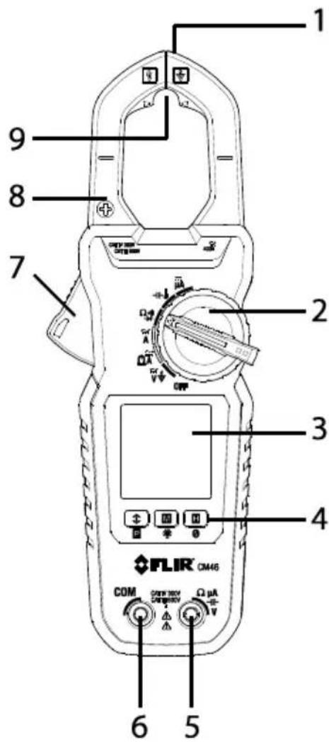
Figure 4-1 Meter Descripon
Note: Baery compartment and Warning text label on back of meter.
4.2 Funcon Switch Posions
| OFF | Switch the meter OFF (full power saving mode) |
 | Measure AC/DC Voltage through the probe inputs |
 | Measure electric eld (EF) using the non-contact voltage detector |
 | Measure AC or DC current through the clamp jaws (CM46) |
 | Measure AC current in the large clamp jaw area (CM42 and CM44) |
 | Measure low AC current through the small clamp jaw area (Accu-TipTM). CM42 and CM44 |
 | Measure low AC or DC current through the small clamp jaw area (Accu-TipTM). CM46 |
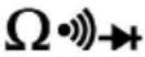 | Measure resistance, connuity, and diode through the probe inputs.The type of measurement is chosen by the modebuon. |
 | Measure capacitance and temperature through the probe inputs. The type of measurement is chosen by thebuon. CM44 and CM46 |
 | Measure DC microamperes (current) through the probe inputs. CM44 and CM46 |
4.3 Funcon Buons
 | Short presses to access and step through MIN-MAX-AVG recorded readings. Long press to exit the mode. |
| Long press to access 80ms PEAK RMS mode. CM44 and CM46. | |
 | Short presses to step through available modes for selected funcon |
 | Long press to switch the display backlight ON or OFF. Backlight switches o automacally aer 32 seconds (approx.). |
 | Short presses to access/exit the display hold mode |
 | Relave Zero CM44Relave & DC Zero CM46 |
4.4 Display Icons and Indicators
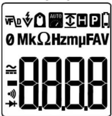
Figure 4-2 Display Icon Descripons
Refer to Fig. 4-2 above for the display icon descripons below:
 | Meter is displaying maximum (up arrow), minimum (down arrow) or average reading (up and down arrows) |
| [3T6S] | 80ms PEAK current/voltage rms mode |
 | Low current Accu-TipTM mode |
 | Auto range mode |
 | Display Hold mode |
 | Low baery voltage warning |
| AC current or voltage measurement | |
 | DC current or voltage measurement |
| [6W01] | Connuity funcon |
 | Diode test |
 | Ohm symbol. Unit of measure for Resistance and Connuity. |
| [6W01] | Unit of measure for current (Amps or Amperes). |
 | EF voltage detector mode |
| [6W01] | Volt. Unit of measure for Voltage |
| [6W01] | Farad. Unit of measure for Capacitance |
| [6W01] | Hertz. Unit of measure for Frequency |
| [6W01] | 10^3 (kilo) |
| [6W01] | 10^-3 (milli) |
| [6W01] | 10^-6 (micro) |
| [6W01] | VFD mode (low pass Iter) icon |
| [6W01] | Relave Zero CM44Relave & DC Zero CM46 |
Notes:
Before operang the device, you must read, understand, and follow all instrucons, dangers, warnings, cauons, and notes.
When the meter is not in use, the funcon switch should be set to the OFF posion.
When connecng the probe leads to the device under test, connect the negave lead before connecng the posive lead. When removing the probe leads, remove the posive lead before removing the negave lead.
Before and aer hazardous voltage measurements, test the voltage function on a known source (such as line voltage) to determine proper meter functionality.
5.1 Powering the Meter
-
Set the funcon switch to any posion to switch the meter ON.
-
If the low baery voltage warning is displayed or if the meter does not power on, replace the baeries. See Secon 6.4 Baery Replacement.
5.2 Intelligent Auto Power OFF (APO) feature
The Auto-Power-o (APO) features switches the meter o automacally aer approximately 32 minutes of inactivity to conserve baery energy. The meter will not switch o if any of the following conditions are met:
- Rotary switch or push buon operaon
- If the measured reading is >8.5% of the full scale range (for example, in the 60A range, 8.5% of 60A = 5.1A; therefore, if the measurement is >5.1A the APO funcon will be disabled and if the measurement is <5.1A the APO funcon will operate normally).
• Non-OL readings for Resistance, Connuity or Diode funcon
• Non-zero readings for Hz funcon
To wake the meter from APO, short press the mode button, or turn the rotary switch OFF and then back on. Always turn the rotary switch to the OFF posion when the meter is not in use.
5.3 Auto Range
The meter automacally selects the most appropriate measurement scale. The indicator is displayed to inform the user that Auto Range is funconing.

5.4 Out-of-range Warning
If the input is out-of-range, OL is displayed.
5.5 Voltage Measurements
CAUTION! Use cauon when the measured voltage is greater than 30 V DC or AC RMS
- Set the funcon switch to the posion*.
- Insert the black probe lead into the negave COM terminal and the red probe lead into the positive V terminal.
- Connect the probe leads in parallel to the part under test.
- Use the M (mode) buon to step through the available sub-funcons: ACV, DCV, ACV+DCV (CM46 only), Line Frequency (Hz), Electric Field (EF) detecon (*CM42 has a dedicated switch posion for EF); see Secon 5.6 Electric Field (EF) Detecon.
- Read the measurement value on the display.
- The VFD (low pass Iter) feature is always acve for ACV measurements. This low pass Iter accommodates measurements on variable frequency drives and measurements in electrically noisy environments.
- For EF voltage detector tesng, see Secon 5.6 Electric Field (EF) Detecon.
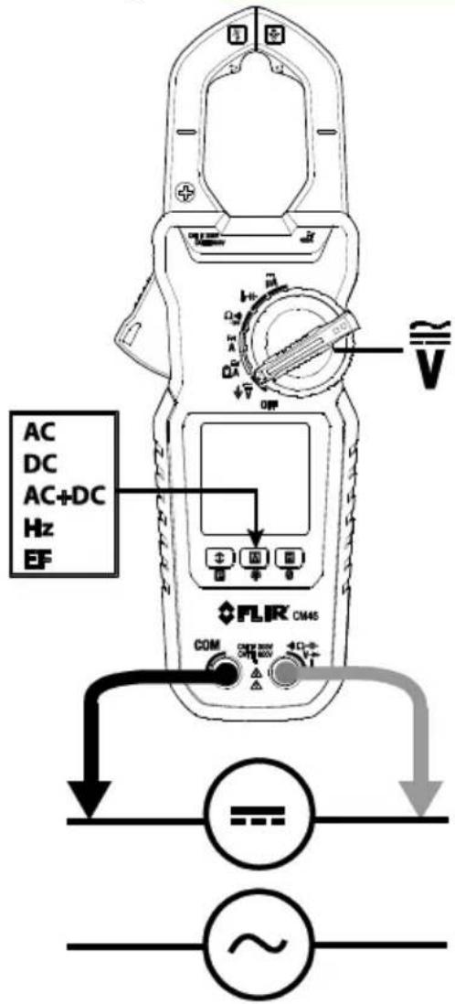
Figure 5-1 Voltage Measurements
5.6 Electric Field (EF) Detecon
For non-contact EF detecon (Fig. 5-2) a sensor is situated at the top right of the meter's clamp jaws. The sensor detects the electric eld emanang from energized conductors. This feature can be used to trace live wiring, locang breaks in circuits, and to determine live or earth connnecons. Refer to Figures 5-2.
- Set the funcon switch to the V posion (for CM44 and CM46) or the dedicated EF posion (CM42).
- If necessary, use the M (mode) buon to step to the EF funcon
- For non-contact EF detecon ensure that the test leads are disconnected from the meter. Place the p of the meter jaws close to the source of electrical energy. If voltage is detected, the meter will beep and display dashes. The rate of beeping and the number of dashes (from 1 to 5) displayed are in proporon to the strength of the detected eld.
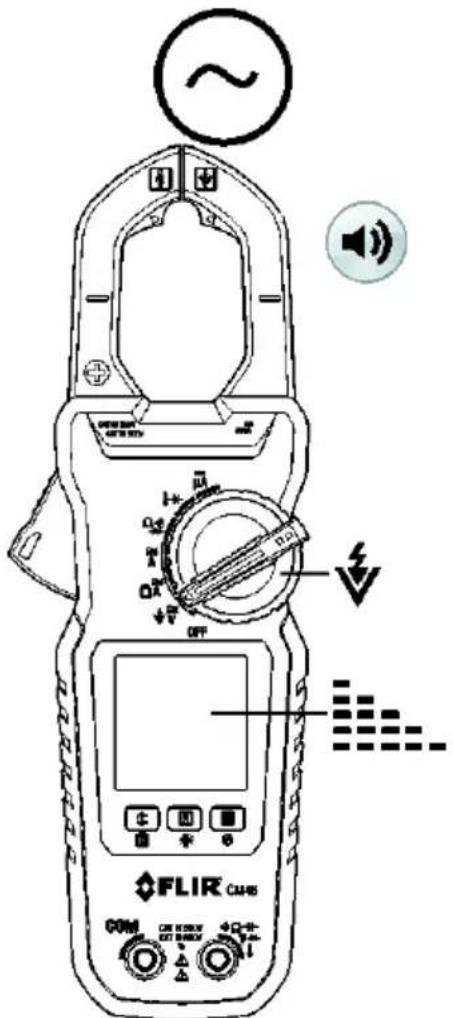
Figure 5-2 Non-Contact Voltage Detect
5.7 Standard Current Clamp Measurements

WARNING!
- Do not measure the current on a circuit when the voltage increases to more than 600V. This can cause damage to the instrument and can cause injury to persons.
- Do not use the meter to measure currents above the rated frequency (400Hz). Circulang currents may cause the magnec circuits of the Jaws to reach hazardous temperatures.
- Disconnect the test leads from the meter before taking Clamp measurements.
• Measurement Preparaon - For clamp-on current measurements, press the jaw trigger and clamp the jaws around the conductor(s) of only one pole of a circuit.
- Ensure that the jaws are completely closed. Enclosing conductor(s) of more than one pole of a circuit may result in dierenal current measurements.
- Align the conductor(s) to the Jaws center indicators as close as possible.
- Adjacent current-carrying devices such as transformers, motors and conductor wires may act measurement accuracy.
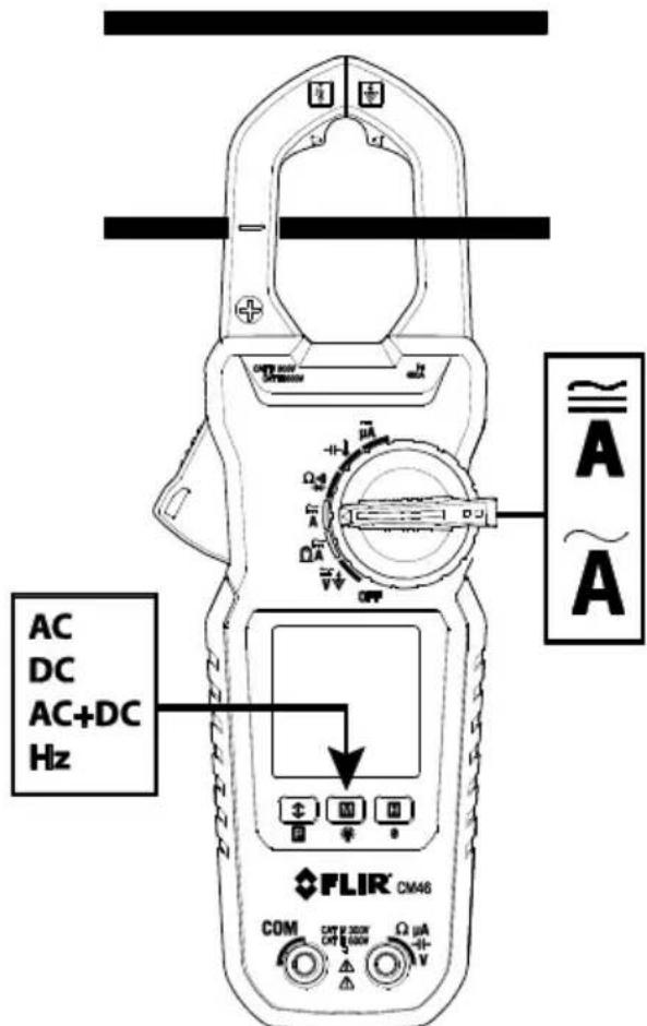
Figure 5-3 Correct and incorrect clamping
- Ensure that the probe leads are disconnected from the meter.
- Set the funcon switch to the (AC) , (AC, DC, or AC+DC) . DC and AC+DC measurements are available on the CM46 only. For low current measurements please refer to Secon 5.8.
- Use the M (mode) buon to select AC, DC (CM46), AC+DC (CM46), or frequency (Hz).
- For DC Current measurements (CM46), with no conductors in the clamp, press the Zero buon to enable DC Zero. The display will show "dc_0" and the display will zero.
- Press the trigger to open the clamp jaws and fully enclose one pole of a circuit—refer to Fig. 5-3. For opmum results, center the conductor in the jaws.
- Read the current value on the display.
5.8 Low Current Accu-Tip™ Clamp Measurements

WARNING!
- Do not measure the current on a circuit when the voltage increases to more than 600V. This can cause damage to the instrument and can cause injury to persons.
- Do not use the meter to measure currents above the rated frequency (400Hz). Circulang currents may cause the magnec circuits of the Jaws to reach hazardous temperatures.
- Disconnect the test leads from the meter before taking Clamp measurements.
Measurement Preparaon
- For clamp-on current measurements, press the jaw trigger and clamp the jaws around the conductor(s) of only one pole of a circuit. See Fig. 5-5.
- Ensure that the jaws are completely closed. Enclosing conductor(s) of more than one pole of a circuit may result in dierenal current measurements.
- Align the conductor(s) to the top of the Jaws center, in the dedicated low current Accu-Tip ^TM area, as shown, for the best accuracy. The maximum allowable conductor size is 8.8mm (0.35").
- Adjacent current-carrying devices such as transformers, motors and conductor wires may aect measurement accuracy.
- Ensure that the probe leads are disconnected from the meter.
Measurements
- Set funcon switch to the position
- Use the M (mode) buon to select AC (All models), DC (CM46), or AC+DC (CM46)
- Press the trigger to open the clamp jaws. Fully enclose the conductor(s) of a single pole—refer to Figure 5.4
- Read the current value on the display.
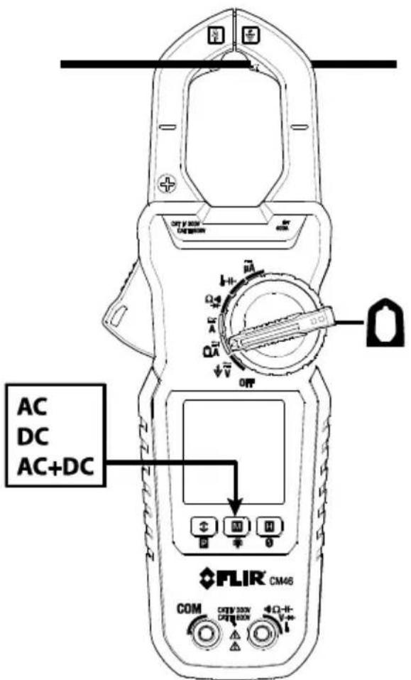
Figure 5-4 Low Current Clamp Measurements
5.9 DC A Current Test Lead Measurements (CM44 and CM46)
- Set the funcon switch to the A posion.
- Insert the black probe lead into the negave COM terminal and the red probe lead into the posive terminal.
- Touch the ps of the probe in series with the circuit under test as shown in Fig. 5-5.
- Read the current value on the display.
The DCμA funcon is designed especially for HVAC ame sensor applicaons. The 0.1μA resoluon is useful for identifying the very small current changes in ame detector applicaons. Flame signal current check should indicate steady ame signal of at least 2μA for a reccaon type, or 1.5μA for an ultraviolet type (8μA for self-checking systems). For ame signal currents with inadequate strength or with uctuaons beyond 10%, check the following to avoid the risk of unwanted ame relay dropout:
For gas or oil ames (UV):
- Low supply voltage
- Detector locaon
• Defective detector wiring - Dirty viewing windows
For oil ames (Photocell):
- Detector locaon & wiring
- Smoky ame or poorly adjusted air shuer
- Faulty Photocell
• Temperature > 165 °F (74 °C) at photocell
For gas ames (Flame Rod):
- Ignion interference (A ame signal current dience with the ignition both on and o greater than 0.5μA indicates the presence of ignition interference)
- Insucient ground (must be at least 4 mes the detector area)
- Flame liing o burner head (ground), or not connuously in contact with the ame rod
- Temperature > 600 °F (316 °C) at the ame electrode insulator causing short to ground.
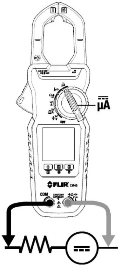
Figure 5-5 μADC Measurements
5.10 Resistance Measurements

WARNING! Do not perform resistance tests before removing the power from resistors and other devices under test during a measurement. Injury to persons can occur.
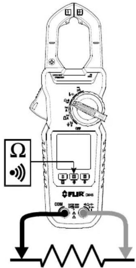
- Set the funcon switch to the position.
- Use the M (mode) buon to select resistance mode.
- Insert the black probe lead into the negave COM terminal and the red probe lead into the positive terminal.
- Touch the ps of the probe across the circuit or component under test (see Fig. 5-6).
- Read the resistance value on the display.
Figure 5-6 Resistance/Connuity Measurements
5.11 Connuity Tests

WARNING! Do not perform connuity tests before removing the power to the component, circuit, or other device under test during a measurement. Injury to persons occur.
- Set the funcon switch to the posion.
- Insert the black probe lead into the negave COM terminal and the red probe lead into the positive terminal. Refer to Fig. 5-6 for conncon example.
- Use the M (mode) buon to select connuity measurement. The indicator will be displayed.
- Touch the ps of the probe across the circuit or component under test (see Fig. 5-6).
- If the resistance measurement < 10 , the meter will beep. If the resistance measurement is >250 , the meter will not beep. Between 10 and 250 , the meter will stop beeping at an unspecified point.
5.12 Capacitance Measurements (CM44 and CM46)

WARNING! Do not perform capacitance tests before removing the power to the capacitor or to other devices under test during a measurement. Injury to persons can occur.
- Set the funcon switch to the position.
- Use the M (mode) buon to select capacitance funcon (capacitor symbol must be displayed).
- Insert the black probe lead into the negave COM terminal and the red probe lead into the positive terminal.
- Touch the ps of the probe across the part under test (see Fig. 5-7).
- Read the capacitance value on the display.
Note: For very large capacitance values, several seconds may be required for the measurement to sele and for the nal reading to stabilize.
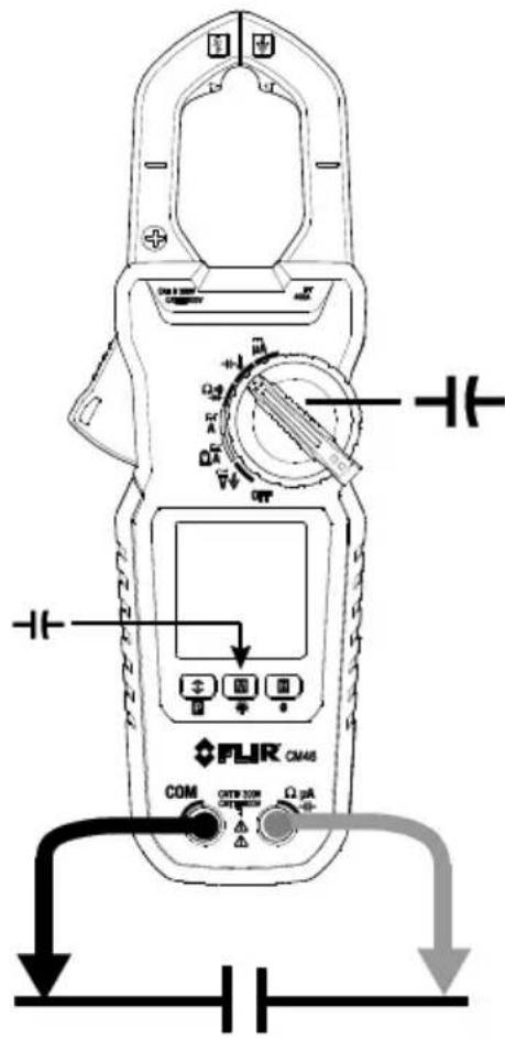
Figure 5-7 Capacitance Measurements
5.13 Temperature Measurements (CM44 and CM46)
Insert the banana plug Type-K temperature bead probe into the meter's input terminals observing correct polarity.
A plug adapter with banana plug to Type-K socket (to adapt to other Type-K standard mini plug temperature probes) can be obtained oponally.
Supplied thermocouple is rated for -20 250^ (-4\~482°F) only and therefore not rated for the enre specied temperature range of the meter.
-
Set the funcon switch to the pasion.
-
Use the M (mode) buon to select degrees F or degrees C for temperature units.
-
Insert the temperature probe banana plugs into the negave COM terminal and positive terminal observing correct polarity.
-
Touch the p of the temperature probe to the surface under test or simply hold the temperature probe in air to measure the air temperature (see Fig. 5-8).
-
Read the temperature value on the display.
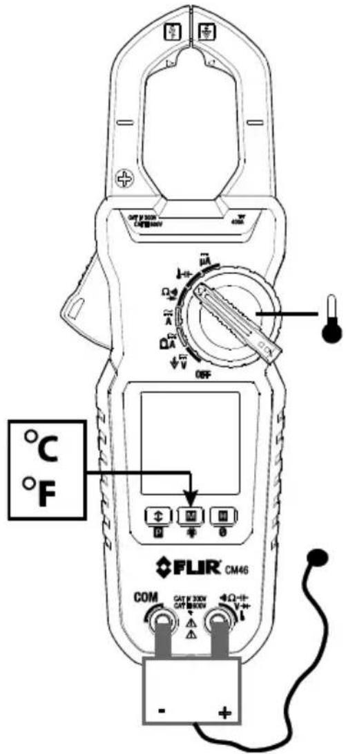
Figure 5-8 Temperature Measurements
5.14 Diode Tests

WARNING! Do not perform diode tests before removing the power to the diode or other devices under test during a measurement. Injury to persons can occur.
- Set the funcon switch to the diode portion.
- Insert the black probe lead into the negave COM terminal and the red probe lead into the positive terminal.
- Use the M (mode) buon to select the diode test funcon. The diode indicator will be displayed.
- Touch the ps of the probe across the diode or semiconductor juncon under test (see Fig. 5-9).
- If the reading is between 0.40 and 0.90 ~V in one direcon and OL (overload) in the opposite direcon, the component is good. If the measurement is 0V in both direcons (shorted) or OL in both direcons (open), the component is bad.
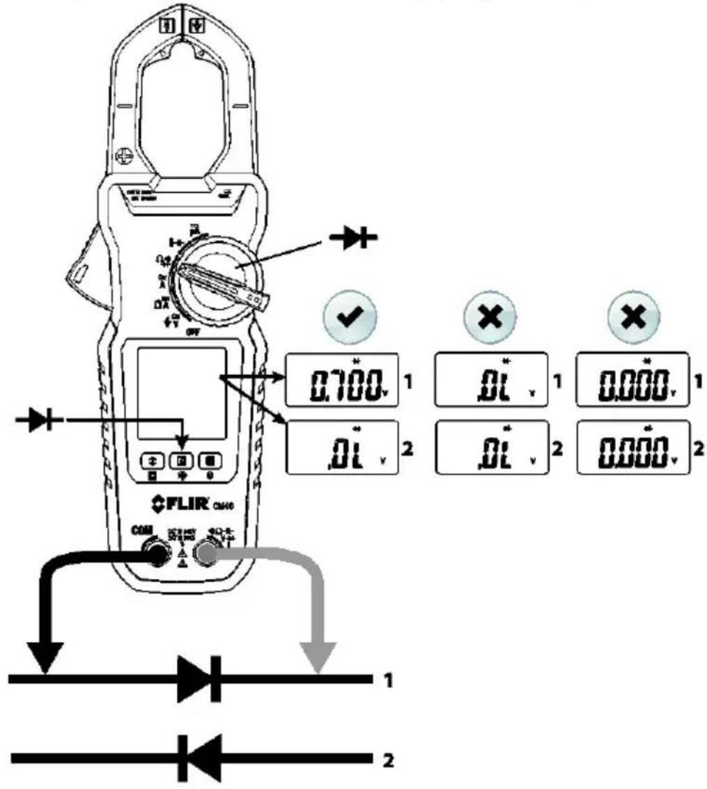
Figure 5-9 Diode Tests
5.15 Relave / DC Zero Modes (CM44 and CM46)
DC Zero is available for DCA & DC+ACA funcons. All other funcons make use of the Relave funcon.
DC ZERO
To zero (oset) a non-zero DCA residual signal caused by magnec hysteresis of the jaws (for DCA and DCA+ACA funcons), long press the H_2O_3 on to acvate/re-acvate. For best accuracy, apply this technique before making any single DCA or DCA+ACA measurement. The meter displays “dc_0” briefy to conrm acvaon. The beeper will emit 3 short beeps if the residual is beyond a reasonable hysteresis reading of ±5 DCA.
RELATIVE MODE
To access the Relave funcon, long press the ☑ buon and the display icon ☑ will appear. The measurement value displayed when the buon is pressed will be stored by the meter as a reference value. Subsequent measurements made, while the Relave mode is acve, will be compared to the stored reference and the meter will display the dience between the stored reference and the actual measurement. Long press the ☑ buon to exit this mode and the display icon ☑ will switch o.
5.16 MIN/MAX/AVG Recording
In MIN/MAX/AVG record mode, the meter captures and displays the Minimum, Maximum, and Average readings and updates only when a change in measurement value is registered.
Short press the button to access the recording mode. The MAX, MIN, and AVG icon will appear indicang that the meter is now recording MAX, MIN, and AVG readings (but displaying real me readings).
Short press the ➕ on to step through the recorded MAX , MIN ↑, and AVG values.

Long press the button to exit this mode. The icons will switch o. The meter will return to normal operaon and the MAX, MIN, and AVG memories will be reset. The Auto Power OFF feature is disabled when the meter is in the MIN-MAX-AVG recording mode.
5.17 VFD Mode (low pass Iter)
The VFD feature eliminates high frequency noise in voltage measurements by means of a low-pass Iter. The VFD mode is designed for variable frequency drive (VFD) measurements. This mode is always acve for ACV and Hz measurements and the VFD display icon is displayed
5.18 Display Hold Funcon
In Display Hold mode, the reading is held on the display.
Short press the H (hold) buon to toggle the Display Hold funcon ON and OFF.
In Hold mode, the H indicator is displayed.
5.19 Display Backlighng
A long press of the ☐ion acvates/deacvates the backlighting. The backlight switches o automacally aer approximately 32 seconds to conserve baery energy.
5.20 PEAK Mode (CM44 and CM46)
A long press of the Puon arms the Peak mode feature. The LCD icon is played when Peak mode is acve. Measurements made with Peak mode acvated capture inrush current or voltage RMS values. The Peak measurement window is 80ms in duraon. Auto-Power-O is disabled automacally in this mode. A long press of the buon switches this feature o.

6. Maintenance

WARNING!
To avoid electrical shock, disconnect the meter from any circuit, remove the test leads from the input jacks and turn OFF the meter before opening the meter's housing. Do not operate with an open housing.
6.1 Troubleshoong Tips
If the instrument fails to operate, check the baeries and the test leads, and replace as necessary. Double check the procedures outlined in this manual.
If the instrument's positive input terminal has been subjected to a high voltage transient (caused by lightning or a switching surge to the system under test), the impedance of the protective components in series might be compromised (creang a high impedance) and will act like an open fuse. Most measuring funcons through this terminal might then be subject to an open circuit. Such components should only be replaced by a qualified technician.
6.2 Accuracy and Calibraon
Accuracy is specified for a period of one year aer calibraon. Periodic calibraon at intervals of one year is recommended to maintain meter accuracy.
6.3 Cleaning and Storage
Periodically wipe the case with a damp cloth and mild detergent; do not use abrasives or solvents. If the meter is not to be used for more than 60 days, remove the baeries and store them separately.
6.4 Baery Replacement
To avoid electrical shock, disconnect the meter if connected to a circuit, remove the probe leads from the terminals, and set the funcon switch to the OFF posion before aempng to replace the baeries.
The rear baery compartment locking screw has a LOCK and UNLOCK posion.
Replace the two (2) standard 1.5V AAA baeries, observing correct polarity.
Secure the baery compartment cover before use.
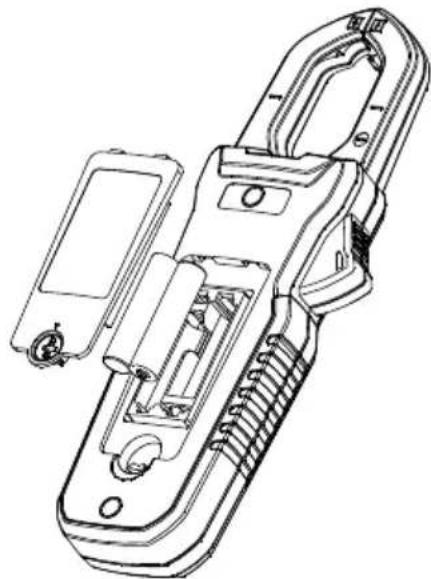
natural_image
Technical line drawing of a handheld device with internal components and mounting holes (no text or symbols)Figure 6-1 Baery installaon
7.1 General specicaons
Display: 3-5/6 digits 6000 counts, backlit
Polarity: Automac
Update Rate: 5 per second nominal
Operang Temperature: 14°F \~ 122°F (-10°C \~ 50°C)
Relave Humidity: Maximum relave humidity 80% for temperature up to 88^ F ( 31^ C) decreasing linearly to 50% relave humidity at 122^ F ( 50^ C)
Polluon degree: 2
Storage Temperature: -4^ 140^ ( -20^ 60^ ), < 80% R.H. (with baery removed)
Altude: Operang 7000. (2000 meters) Max.
Temperature Coecient: nominal 0.15 x (specied accuracy)/ °C @ (32°F \~ 64.4°F [0°C \~ 18°C] or 82.4°F \~ 122°F [28°C \~ 50°C]), or as otherwise specied
Sensing: True RMS
Safety: Double insulaon per UL/IEC/EN61010-1 Ed. 3.0, IEC/EN61010-2-033 Ed. 1.0, CAN/CSA C22.2 No. 61010-1 Ed. 3.0, IEC/EN61010-2-032 Ed. 3.0 & IEC/EN61010-031 Ed. 1.1 to CAT III 600V and CAT IV 300V AC & DC
Transient Protecon: 6.0kV (1.2/50μs surge)
Drop test: 6.6 . (2m)
Overload Protecon:
Current & Hz funcons via jaws: 400ADC/AAC rms <400Hz
Voltage via terminals: 660VDC / 920VAC rms
Other funcons via terminals: 600VDC/VAC rms
E.M.C.: Meets EN61326-1:2013:
Ohm funcons for all Models & DC A for CM44 & CM46:
In an RF eld of 1V/m:
Total Accuracy = Specied Accuracy + 25 digits for OHM & DCμA
Other funcons of all Models:
In an RF eld of 3V/m: Total Accuracy = Specied Accuracy + 20 digits
Power Supply: 1.5V AAA size baery X 2
Power Consumpon: 13mA for Current funcons of Model CM46; 4.3mA for others
Low Baery:
Below approx. 2.85V for Capacitance & Hz funcons
Below approx. 2.5V for other funcons
APO Timing: 32 minutes of inactivity
APO Consumpon: 5μA typical
Dimensions (LxWxH): 8.8 x 3.0 x 1.5 in. (223 x 76 x 37mm) for CM46; 8.5 x 3.0 x 1.5 in. (217 x 76 x 37mm) for CM42 and CM44
Weight: 8.3 oz. (234g) for Model CM46; 6.6 oz. (186g) for Models CM42 and CM44
Jaw opening & Conductor diameter: 1.2 in. (30mm) maximum
Accessories: Test lead set, Quick Start Guide, so carrying pouch, banana plug K-type thermocouple (Models CM44 and CM46)
Oponal purchase accessories: Banana plug to Type-K socket plug adaptor (Models CM44 and CM46)
Advanced Features: Accu-Tip™ low-current range; MAX/MIN/AVG Recording mode; Display Hold; EF-Detecon (NCV); Backlit LCD; 80ms Peak-RMS mode for inrush current (CM46 & CM44 only); Relave/DC Zero (CM46 & CM44 only)
| CAT | Applicaon eld |
| III | Distribuon circuits, machinery, main switching devices close to switchgears, industrial installaons and high current close to distribuon circuits |
| IV | Installaon sources, utility transformers, all outside conductors, counters, protective devices on primary sides and electricity meters |
7.2 Electrical specicaons
Accuracy: ± (% reading + number of digits) or as otherwise specied, at 23°C (73.4°F) ± 5°C (9°F).
DC Voltage
| RANGE | Accuracy |
| 600.0V | 1.0% + 5d |
Input Impedance: 10MΩ, 100 pF nominal
AC Voltage (with Digital Low-Pass Filter)
| RANGE | Accuracy |
| 50Hz ~ 60Hz | |
| 600.0V | 1.0% + 5d |
Input Impedance: 10MΩ, 100 pF nominal
DC+AC Voltage (with Digital Low-Pass Filter) (Model CM46 only)
| RANGE | Accuracy |
| DC, 50Hz ~ 60Hz | |
| 600.0V | 1.2% + 7d |
Input Impedance: 10MΩ, 100 pF nominal
PEAK-rms (ACV & ACA for Models CM44 and CM46)
Response: 80ms to >90%
Audible Connuity Tester
Audible Threshold: 10Ω to 250Ω
Response me: 32 milliseconds approx.
Resistance
| RANGE | Accuracy |
| 600.0Ω, 6.000KΩ, 60.00KΩ | 1.0% + 5d |
Open Circuit Voltage: 1.7VDC typical
Capacitance (Models CM44 and CM46)
| RANGE | Accuracy1 |
| 200.0μF, 2500μF | 2.0% + 4d |
^1 Accuracy specied for lm capacitors or beer
Diode Test
| RANGE | Accuracy |
| 2.000V | 1.5% + 5d |
Test Current: 0.3mA typical; Open Circuit Voltage: < 3.5VDC typical
DCμA (Models CM44 and CM46)
| RANGE | Accuracy | Burden Voltage |
| 200.0μA, 2000μA | 1.0% + 5d | 3.5mV/μA |
Temperature (Models CM44 and CM46)
| RANGE ^2 | Accuracy ^1 |
| -40.0 °C ~ 99.9 °C | 1.0% + 1°C |
| 100 °C ~ 400°C | |
| -40.0 °F ~ 99.9 °F | 1.0% + 2°F |
| 100 °F ~752 °F |
^1 K-type thermocouple range & accuracy not included. Accuracies assume meter interior has the same temperature as the ambient temperature for correct juncon voltage compensaon. Allow adequate me for stabilizaon for significant changes of ambient temperature. Up to an hour, for changes >5^ ( 9^ ), may be required.
^2 Supplied thermocouple is rated for -20250^ ( -4482^ ) only, and therefore not rated for the enre specied temperature range of the meter.
Low current Accu-Tip™ clamp-on ACA
| RANGE | Accuracy 1, 2, 3, 4 |
| 50Hz ~ 60Hz | |
| 60.00A | 1.5% + 5d (CM46); 2.0% + 5d (CM42 and CM44) |
^1 Induced error from adjacent current-carrying conductor:
<0.01A/A for Model CM46
<0.06A/A for Models CM42 and CM44
^2 Specied with Relave/DC Zero mode applied to oset non-zero residual readings
^3 Add 10d to the specied accuracy @ < 4A
^4 Posion the conductor at the center of the Accu-Tip TM area. Conductor size must not exceed (0.35") 8.8mm.
Low current Accu-Tip ^TM clamp-on DCA (Model CM46)
| RANGE | Accuracy 1, 2, 3, 4 |
| 60.00A | 2.0% + 5d |
^1 Induced error from adjacent current-carrying conductor: <0.01A/A
^2 Specied with DC Zero mode applied to oset non-zero residual readings
^3 Add 10d to the specied accuracy @ < 4A
^4 Posion the conductor at the center of the Accu-Tip TM area. Conductor size must not exceed (0.35") 8.8mm.
Low current Accu-Tip™ clamp-on DC+ACA (Model CM46)
| RANGE | Accuracy1, 2, 3, 4 |
| DC, 50Hz ~ 60Hz | |
| 60.00A | 2.0% + 7d |
^1 Induced error from adjacent current-carrying conductor: <0.01A/A
^2 Specied with DC Zero mode applied to oset non-zero residual readings
^3 Add 10d to the specied accuracy @ < 4A
^4 Posion the conductor at the center of the Accu-Tip TM area. Conductor size must not exceed (0.35") 8.8mm.
Standard Clamp-on ACA
| RANGE | CM46 Accuracy1 | CM42 and CM44 Accuracy1,2 |
| 50Hz ~ 100Hz | 50Hz ~ 60Hz | |
| 60.00A3,4, 400.0A | 1.8% + 5d | 2.0% + 5d |
| 100Hz ~ 400Hz | 60Hz ~ 400Hz | |
| 60.00A3,4, 400.0A | 2.0% + 5d5 | 3.0% + 5d5 |
^1 Induced error from adjacent current-carrying conductor:
<0.01A/A for Models CM46
<0.06A/A for Models CM44 & CM42
^2 For CM44 & CM42, specied accuracy is for measurements made at the jaw center. When the conductor is not posioned at the jaw center, add 2% to specied accuracy for posion errors
^3 For CM44 & CM42, add 10d to specied accuracy @ < 6A
^4 For CM46, add 10d to the specied accuracy @ < 9A
^5 Add 3% to the accuracy specicaon for Crest Factor between 1.0 and 2.0. If the Crest Factor is >2.0, the reading may not meet specied tolerances.
Standard Clamp-on DCA (Model CM46)
| RANGE | Accuracy ^1,2 |
| 60.00A ^3 , 400.0A | 2.0% + 5d |
^1 Induced error from adjacent current-carrying conductor: <0.01A/A
^2 Specied with DC Zero mode applied to oset non-zero residual readings
^3 Add 10d to the specied accuracy @ < 9A
Standard Clamp-on DC+ACA (Model CM46)
| RANGE | Accuracy ^1,2 |
| DC, 50Hz ~ 100Hz | |
| 60.00A ^3 , 400.0A | 2.2% + 7d |
| 100Hz ~ 400Hz | |
| 60.00A ^3 , 400.0A | 2.7% + 7d |
^1 Induced error from adjacent current-carrying conductor: <0.01A/A
^2 Specied with DC Zero mode applied to oset non-zero residual readings
^3 Add 10d to the specied accuracy @ < 9A
Hz Line Level Frequency
| Funcon | Sensitivity ^1 (Sine RMS) | Range |
| 600V | 50V | 5.00Hz ~ 999.9Hz |
| 60A (low current mode) | 40A | 50.00Hz ~ 400.0Hz |
| 60A, 400A | 40A | 50.00Hz ~ 400.0Hz |
Accuracy: 1%+5d
^1 DC-bias, if any, not more than 50% of Sine RMS
Non-Contact EF Voltage Detecon
| Typical Voltage | Bar Graph Indicaon |
| 20V (tolerance: 10V ~ 36V) | - |
| 55V (tolerance: 23V ~ 83V) | -- |
| 110V (tolerance: 59V ~ 165V) | --- |
| 220V (tolerance: 124V ~ 330V) | ---- |
| 440V (tolerance: 250V ~ 600V) | ---- |
Indicaon: number of Bargraph segments & audible beep tones proporonal to the detected eld strength
Detecon Frequency: 50/60Hz
Detector: Located Inside the top of the stationary jaw
8. Technical Support
| Main Website | hp://www.ir.com/test |
| Technical Support Website | hp://support.ir.com |
| Technical support Email | TMSupport@ir.com |
| Service/Repair Support Email | Repair@ir.com |
| Support Telephone number | +1 855-499-3662 opon 3 (toll-free) |
FLIR Global Limited Lifetime Warranty
A qualifying FLIR Test and Measurement product (the "Product") purchased either directly from FLIR Commercial Systems Inc. and aliates (FLIR) or from an authorized FLIR distributor or reseller that Purchaser registers on-line with FLIR is eligible for coverage under FLIR's Limited Lifetime Warranty, subject to the terms and conditions in this document. This warranty only applies to purchases of Qualifying Products (see below) purchased and manufactured aer April 1, 2016.
PLEASE READ THIS DOCUMENT CAREFULLY; IT CONTAINS IMPORTANT INFORMATION ABOUT THE PRODUCTS THAT QUALIFY FOR COVERAGE UNDER THE LIMITED LIFETIME WARRANTY, PURCHASER'S OBLIGATIONS, HOW TO ACTIVATE THE WARRANTY, WARRANTY COVERAGE, AND OTHER IMPORTANT TERMS, CONDITIONS, EXCLUSIONS AND DISCLAIMERS.
- PRODUCT REGISTRATION. To qualify for FLIR's Limited Lifetime Warranty, Purchaser must fully register the Product directly with FLIR on-line at http://www.ir.com within Sixty (60) DAYS of the date the Product was purchased by the rst retail customer (the "Purchase Date"). Qualifying PRODUCTS THAT ARE NOT REGISTERED ON-LINE WITHIN SIXTY (60) DAYS OF THE PURCHASE DATE WILL HAVE A LIMITED ONE YEAR WARRANTY FROM DATE OF PURCHASE.
- QUALIFYING PRODUCTS. Upon registraon, Test and Measurement products that qualify for coverage under FLIR's Limited Lifetime Warranty are: MR7x, CM4x, CM7x, CM8x, DMxx, VP5x not including accessories which may have their own warranty.
- WARRANTY PERIODS. For purposes of The Limited Lifetime Warranty, Lifetime is dened as seven years (7) aer the product is no longer manufactured, or ten years (10) from date of purchase, whichever is greater. This Warranty is only applicable to the original owner of the Products. Any Product that is repaired or replaced under warranty is covered under this Limited Lifetime Warranty for one hundred eighty days (180) days from the date of return shipment by FLIR or for the remaining duration of the applicable Warranty Period, whichever is longer.
- LIMITED WARRANTY. In accordance with the terms and conditions of this Limited Lifetime Warranty, and except as excluded or disclaimed in this document, FLIR warrants, from the Purchase Date, that all fully registered Products will conform to FLIR's published Product speciaons and be free from defects in materials and workmanship during the applicable Warranty Period. PURCHASER'S SOLE AND EXCLUSIVE REMEDY UNDER THIS WARRANTY, AT FLIR'S SOLE DISCRETION, IS THE REPAIR OR REPLACEMENT OF DEFECTIVE PRODUCTS IN A MANNER, AND BY A SERVICE CENTER, AUTHORIZED BY FLIR. IF THIS REMEDY IS ADJUDICATED TO BE INSUFFICIENT, FLIR SHALL REFUND PURCHASER'S PAID PURCHASE PRICE AND HAVE NO OTHER OBLIGATION OR LIABILITY TO BUYER WHATSOEVER.
- WARRANTY EXCLUSIONS AND DISCLAIMERS. FLIR MAKES NO OTHER WARRANTY OF ANY KIND WITH RESPECT TO THE PRODUCTS. ALL OTHER WARRANTIES, EXPRESS OR IMPLIED, INCLUDING BUT NOT LIMITED TO IMPLIED WARRANTIES OF MERCHANTABILITY, FITNESS FOR A PARTICULAR PURPOSE (EVEN IF PURCHASER HAS NOTIFIED FLIR OF ITS INTENDED USE FOR THE PRODUCTS), AND NON-INFRINGEMENT ARE EXPRESSLY EXCLUDED FROM THIS AGREEMENT.
THIS WARRANTY EXPRESSLY EXCLUDES ROUTINE PRODUCT MAINTENANCE, SOFTWARE UPDATES, AND REPLACEMENT OF MANUALS, FUSES, OR DISPOSABLE BATTERIES. FLIR FURTHER EXPRESSLY DISCLAIMS ANY WARRANTY COVERAGE WHERE THE ALLEGED NONCONFORMITY IS DUE TO NORMAL WEAR AND TEAR, OTHER ALTERATION, MODIFICATION, REPAIR, ATTEMPTED REPAIR, IMPROPER USE, IMPROPER MAINTENANCE, NEGLECT, ABUSE, IMPROPER STORAGE, FAILURE TO FOLLOW ANY PRODUCT INSTRUCTIONS, DAMAGE (WHETHER CAUSED BY ACCIDENT OR OTHERWISE), OR ANY OTHER IMPROPER CARE OR HANDING OF THE PRODUCTS CAUSED BY ANYONE OTHER THAN FLIR OR FLIR'S EXPRESSLY AUTHORIZED DESIGNEE. THIS DOCUMENT CONTAINS THE ENTIRE WARRANTY AGREEMENT BETWEEN PURCHASER AND FLIR AND SUPERSEDES ALL PRIOR WARRANTY NEGOTIATIONS, AGREEMENTS, PROMISES AND UNDERSTANDINGS BETWEEN PURCHASER AND FLIR. THIS WARRANTY MAY NOT BE ALTERED WITHOUT THE EXPRESS WRITTEN CONSENT OF FLIR.
- WARRANTY RETURN, REPAIR AND REPLACEMENT. To be eligible for warranty repair or replacement, Purchaser must noty FLIR within thirty (30) days of discovering of any apparent defect in materials or workmanship. Before Purchaser may return a Product for warranty service or repair, Purchaser must rest obtain a returned material authorizaon (RMA) number from FLIR. To obtain the RMA number Owner must provide an original proof of purchase. For additional informaon, to noty FLIR of an apparent defect in materials or workmanship, or to request an RMA number, visit http://www.ir.com. Purchaser is solely responsible for complying with all RMA instrucons provided by FLIR including but not limited to adequately packaging the Product for shipment to FLIR and for all packaging and shipping costs. FLIR will pay for returning to Purchaser any Product that FLIR repairs or replaces under warranty.
FLIR reserves the right to determine, in its sole discretion, whether a returned Product is covered under Warranty. If FLIR determines that any returned Product is not covered under Warranty or is otherwise excluded from Warranty coverage, FLIR may charge Purchaser a reasonable handling fee and return the Product to Purchaser, at Purchaser's expense, or oer Purchaser the opon of handling the Product as a non-warranty return.
- NON-WARRANTY RETURN. Purchaser may request that FLIR evaluate and service or repair a Product not covered under warranty, which FLIR may agree to do in its sole discretion. Before Purchaser returns a Product for non-warranty evaluaon and repair, Purchaser must contact FLIR by vising hp://www.ir.com to request an evaluaon and obtain an RMA. Purchaser is solely responsible for complying with all RMA instrucons provided by FLIR including but not limited to adequately packaging the Product for shipment to FLIR and for all packaging and shipping costs. Upon receipt of an authorized non-warranty return, FLIR will evaluate the Product and contact Purchaser regarding the feasibility of and the costs and fees associated with Purchaser's request. Purchaser shall be responsible for the reasonable cost of FLIR's evaluaon, for the cost of any repairs or services authorized by Purchaser, and for the cost of repackaging and returning the Product to Purchaser.
Any non-warranty repair of a Product is warranted for one hundred eighty days (180) days from the date of return shipment by FLIR to be free from defects in materials and workmanship only, subject to all of the limitaons, exclusions and disclaimers in this document.
Corporate Headquarters
FLIR Systems, Inc.
2770 SW Parkway Avenue
Wilsonville, OR 97070 USA
Telephone: +1 503-498-3547
Customer Support
Technical Support Website hp://support.ir.com
Technical Support Email TMSupport@ir.com
Service and Repair Email Repair@ir.com
Customer Support Telephone +1 855-499-3662 opon 3 (toll free)
Publicaon Idencaon No.: CM4x-en-US
Release Version: AA
Release Date: 2016 August
Language: en-US