
EGP8-PPED - Controller Irritrol - Free user manual and instructions
Find the device manual for free EGP8-PPED Irritrol in PDF.


| Product Type | Irrigation Controller |
| Brand | Irritrol |
| Model | EGP8-PPED |
| Dimensions (Wall Mount) | 11" W x 16" H x 5.625" D (27.9 x 40.6 x 14.29 cm) |
| Dimensions (Pedestal PSB) | 16.5" W x 38" H x 17.25" D (41.9 x 96.5 x 43.8 cm) |
| Dimensions (Pedestal SPED) | 16" W x 34" H x 16" D (40.6 x 86.4 x 40.6 cm) |
| Power Input | 120 VAC ±10%, 50/60 Hz |
| Power Output | 24 VAC ±10%, 50/60 Hz |
| Max Load Per Station | 0.5 A @ 24 VAC |
| Total Max Load | 1.5 A @ 24 VAC |
| Operating Temperature | +14°F to +140°F (-10°C to +60°C) |
| Storage Temperature | -22°F to +149°F (-30°C to +65°C) |
| Number of Stations | Up to 48 (standard) / Up to 202 (with two-wire decoder) |
| Number of Programs | Up to 8 (standard) / Up to 16 (decoder) |
| Memory Type | Non-volatile NVRAM; time/date backup ~30 days |
| Scheduling Options | ET-based, 14-day, skip days, odd/even, cycle-and-soak |
| Flow Sensor Support | Up to 2 sensors; standard or custom configuration |
| Two-Wire Decoder Support | Optional module; up to 100 decoders, 202 outputs |
| Surge Protection | 6 kV common mode, 1 kV normal mode (excluding decoder models) |
| Rain Sensor | Yes, compatible with rain sensor or weather station |
| Audible Alert | Optional chirp every 6 seconds on alarm |
| Water Off Mode | Timed from 1 to 9 days |
| Security Access | 4-digit code with restricted or no access levels |
| Display | Large LCD with backlight; auto-dim after 5 minutes |
| Cleaning and Maintenance | Clean with dry cloth; avoid liquids; keep enclosure dry |
| Spare Parts Available | Station output modules, decoder boards, iCentral modem, flow sensors |
Frequently Asked Questions - EGP8-PPED Irritrol
User questions about EGP8-PPED Irritrol
0 question about this device. Answer the ones you know or ask your own.
Ask a new question about this device
Download the instructions for your Controller in PDF format for free! Find your manual EGP8-PPED - Irritrol and take your electronic device back in hand. On this page are published all the documents necessary for the use of your device. EGP8-PPED by Irritrol.
USER MANUAL EGP8-PPED Irritrol
• Installation
- Setup
- Programming
• Operation
- Troubleshooting
![RAIN MASTER™ EAGLE PLUS ALARM TRIGATION SU 08:20:15A WK1 ▼.# VALID PGM:14 [MAIN] PRESS ENTER PROGRAM SETUP HOME IRritrol. MANUAL REVIEW WATER OFF](/content/2026/05/1108149/images/7f5ea2ea915f24014aea5d16c2ba9bf1ec647ce89e1266ba570f68b30874ee19.jpg)
Irritrol®
Introduction
Thank you for choosing the Irritrol Rain Master Eagle Plus controller for your landscape irrigation system. We at Irritrol take great pride in developing and building the finest irrigation products in the world, and are confident that your new Rain Master Eagle Plus will provide the control features, resource management tools, ease of use and robust design for years of dependable service.
Programming Features
- Station Run Time from 1 minute to 23 hours and 59 minutes, in 1-minute increments.
• Station delay setting from 1 minute to 19 minutes and 59 seconds.
• Cycle run time, Maximum Cycle time, and Soak time on a per-station basis - Pump activation independent of the master valve on a per-program basis
• Program stacking or single program operation - Watering day routine options on a per-program basis include: 14-Day, Skip Days and Odd/Even-numbered days.
- Definable watering window from 1 minute to 24 hours.
• Cycle-and-Soak or standard run time programming on a per-program basis.
• Copy functions for program-to-program and station run time.
• Programmable Master Valve and a Pump output control capabilities:
Automatic Watering Operations
• Evapotranspiration (ET) based scheduling.
- Percentage adjustment on a per-program basis to allow an increase or decrease of all station runtimes within that program from 0 – 300% in 1% increments.
• Calculated station run time executed to the nearest second.
• Programmable Water Off to postpone irrigation from 1 to 9 days.
- Automatic minimization of the water window by dynamically scheduling station starts when other stations are in the Soak mode.
Evapotranspiration (ET) Features
• ET processing on a per program basis.
• Multiple ET sources as the basis for its ET calculations:
• Historical ET data
• Manually entered ET data
• Weather Center II weather station
- Internet (with iCentral communication enabled).
Control Module Features
- Non-volatile memory retains all controller setup and programming information during power outages or seasonal shutdowns.
- A real-time clock with non-volatile backup to maintain the current date and time during power outages without the need of batteries.
- Automatically monitors all critical operating voltages and resets microprocessor during power "brown-out" or error conditions.
- Automatic electronic fuse resets automatically - eliminates fuses or circuit breakers.
- Automatic resumption of watering programs after power outage from the point of interruption.
• Automatically detects problems on all output and input circuits.
• Built-in self-test for internal circuitry. - Robust surge protection on field output circuits.
Input Monitoring Features
- Rain sensor ready—accepts rain sensor or weather station input.
- Connectivity and input for two flow-sensing devices.
- Programmable flow sensor pipe sizes for standard Rain Master flow sensors and non-standard pipe sizes.
• Programmable flow monitoring for:
• Mainline flow limit
• Unscheduled flow limit
• Single-station flow limit
• Sample delay
• Measured station flow.
Two-Wire Decoder System Control Features
(Two-Wire Decoder System Models Only)
- Two-Wire Decoder board installs in place of standard station output boards
• Fully integrated Two-Wire Decoder capabilities - Provides control of up to 100 decoders for a total of 202 field outputs
• Auto detection and configuration during power-up
• Decoder programming and monitoring capabilities include:
• Decoder and station number association
• Output current
• Station short/open circuit
• Decoder presence detection.
Table of Contents
◆ Control Module Overview ......2
◆ Controller Interior Component Overview ......4
Selecting the Controller Setup Options ......6
Setting the Current Time and Date 7
Setting a Security Access Code 9
Setting the Program Stack Option 11
Setting the Station Delay Option 12
Setting the Master Valve Option 13
Setting the Regional Options 14
Setting the Odd/Even Day Option 15
Setting the Audible Alert Option 16
♦ Setting the Timed Water-Off Mode ....17
Setting the Water Window Duration 18
Selecting the Program Setup Options 19
Setting the Program Type Option 20
Setting the Program Odd/Even Days Option 21
Setting the Program Master Valve/Pump Control Options 22
Setting the Program Weather Options 23
- Selecting the ET Setup Options 24
Selecting the Flow Sensor Setup and Operation Options 25
Setting the Usage Option 26
Setting the Standard/Custom Sensor Options 26
♦ Setting the Flow Limits Options ......27
Setting the Delay Option 28
Setting the Learned Flow Options 28
♦ Resetting the Flow Totalizer 29
Setting the Communications Options 30
◆ Two-Wire Decoder System Setup ....31
◆ Programming the Decoders ....31
◆ Two-Wire Decoder System Setup ....31
◆ Programming the Decoders ....31
♦ Testing the Two-Wire Decoder System 33
- Single Station Test ....33
♦ Find Decoders Test 34
- All Stations Test 35
◆ Programming for Automatic Operation ....36
♦ Creating a New Program 36
Setting a Two-Week Watering Schedule 37
Setting a Skip-Day Watering Schedule 37
♦ Setting Program Start Times 38
♦ Assigning the Station Run Time 38
Setting a Cycle and Soak Station Run Time 39
❖ Modifying a Program: 41
♦ Adjusting Program Percent Value 42
♦ Deleting a Program 42
✿ Copying a Program or Runtime ....43
◆To Copy a Program 43
◆ To Copy a Run Time 44
❖ Review Mode 45
◆ Program Review ....45
♦ Alarm Review....46
◆Comm Review 46
◆Flow Review 46
♦ Irrigation Review ....47
♦ ET Review 47
❖ Manual Watering Operations 48
◆ Manual Station Operation 48
◆ Manual Program Operation 49
◆ Manual Multi-Station Operation 50
◆ Manual Test Functions....51
◆ Alarms Feature ....52
♦ Alarm Categories ....52
◆Field Wire Fault Detection 52
◆Flow Detection 52
♦ Clearing Alarms 53
♦Analyzing Alarms 54
♦ General Alarms 54
♦ Flow Sensor Alarms 56
- Rain Sensor or Weather Station Alarms 58
- Two-Wire Decoder System Alarms .... 59
Appendix A - General Specifications 62
Appendix B - Flow Sensor Specifications 63
Appendix C - Error Code Reference Chart 64
Appendix D - FCC Rules-Electromagnetic Compatibility .....65
Control Module Overview
![RAIN MASTER™ EAGLE PLUS 1 SU 08:20:15A WK1 ▼ VALID PGM:14 [MAIN] 2 3 ALARM INNOVATION PRESS 4 5 PROGRAM SETUP HOME MANUAL REVIEW MASTER OFF 6 Irritrol 7](/content/2026/05/1108149/images/e1f84b56396f52671b37302afa32df4b81fe79f8b20317e69d0813be7434e73f.jpg)
1 - Large LCD Display
The large format LCD display presents all setup, programming, system control and monitoring functions in an interactive menu-driven format.
Note: To conserve power, the LCD backlight dims automatically after five minutes of inactivity. The backlight is restored automatically with any controller input.
The Home screen is displayed by default when the controller is in the standby mode to provide basic controller status information.
The top line of the Home screen provides the current day (1), current time (2), and week 1 or week 2 of the two-week watering schedule (3). When equipped for iCentral communications, an antenna symbol (4) with signal strength indication bars will be shown.
The second line indicates the current number of configured automatic programs: None or 1–8 for standard systems, or 1–16 for Two-Wire systems. When the controller is in the Water Off mode, WATER OFF is displayed.
The bottom line of the Home screen provides: Main menu access (5), the pending number of alarms (6), and display sequence arrow(s) (7).
![TH 12:01:00A WK1 ▼.a VALID PGM: NONE [MAIN]-ALARMS( 1)-↓↑ TH 12:00:00A WK1 ▼.a VALID PGM: NONE [MAIN] WATER OFF 1)-↓↑ TH 12:00:00A WK1 ▼.a VALID PGM: NONE [MAIN]-ALARMS( 1)-↓↑ ① ② ③ ④ ⑤ ⑥ ⑦](/content/2026/05/1108149/images/9ba671c8fa0a64e96f7f6619ce1a61e96e51969cc348f1fd5613f42341e7eb1a.jpg)
2 - Screen Sequence Keys
The NEXT ▼ and BACK screen sequence keys are associated with the corresponding ↓ and arrow symbols when displayed. Pressing a sequence key steps forward or backward through a multiple-screen sequence.
3 - Irrigation and Alarm Monitors
The Irrigation LED monitor illuminates to indicate system watering activity. The Alarm LED monitor illuminates when a system Alarm or Alert is generated. The Alarm monitor LED will remain illuminated until cleared by the user. An audible Alert option can be enabled that will “chirp” every six seconds to indicate one or more Alarm and or Alert conditions.
4 - Selection Dial
The selection Dial is the main user-interface component, providing a single rotary/push-button dial to select and input all controller setup and operating features.
5 - Direct Access Menu Keys
Direct access to each primary menu function is provided by pressing the corresponding selection key as follows:
PROGRAM ☐ Key – Selects the MAIN PROGRAM menu. Provides program-related options including: new program setup, existing program review, program modification, deletion, and copy functions.
SETUP 📂 Key – Selects the MAIN SETUP menu. Provides access to all setup option menus including: CONTROLLER operating options, FLOW monitor setup, PROGRAM operating options, COMM setup, ET setup, and TWO-WIRE system setup.
MANUAL Key – Selects the MANUAL OPERATIONS menu enabling manual control operations including: SINGLE STATION and MULTI-STATION operation, PROGRAM operation and multiple TEST functions.
REVIEW Key – Selects the REVIEW menu for quick access to all controller PROGRAM details, historical data logs for IRRIGATION events, ALARM events, FLOW results, ET rates, iCentral communications and controller software version.
HOME Key – Returns directly to the HOME menu from any location within the menu hierarchy.
6 - WATER OFF Key – Terminates all automatic watering activity. When selected, all current automatic controller operation shuts down and remains off until the WATER OFF mode is released. The Water Off LED monitor illuminates when the controller is in the WATER OFF mode.
7 - Pro Max Remote Control Receptacle – Provides easy access for connection and remote operation with the (optional) Pro Max remote control system.
Controller Interior Component Overview

Wall-mount Enclosure

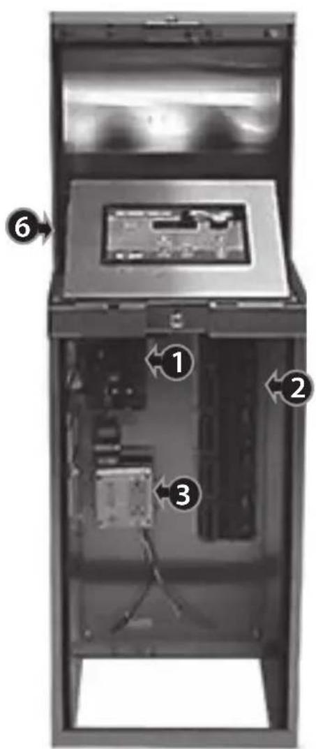
PSB Pedestal-mount Enclosure
SPED Pedestal-mount Enclosure
1 - Master Valve/Pump/Sensor Module This module provides connections for all auxiliary components including: pump (1), master valve (2), field common (3), two flow sensors (3), a Weather Center II (5) or a rain/freeze sensor (6), and a 24 VAC power source.
2 - Station Output Module
(standard configuration)
Each output module provides connections for eight station outputs (1) and two field commons (2). Up to six station output modules can be installed for a total of 48 station outputs.
3 - Main Power Connection
Terminal block (wall-mount models) or junction box provide connections for Line, Neutral, and Equipment Ground wiring. Pedestal models provide On/Off switch and power outlet.
4 - Two-Wire Decoder Module (optional)
A single Two-Wire Decoder module replaces the 8-station output board(s) and connects to the control module via a two-wire, plug-in cable assembly. The Decoder module provides two separate decoder control wire pairs (1) and a quick-disconnect terminal block to facilitate decoder programming (2).
5 - iCentral with GSM Communications Modem (optional)
The iCentral modem mounts on the back of the control module to provide wireless communications capability with the iCentral control system.
6 - iCentral Antenna (optional)
External antenna (optional) provides unity gain and 200 watt power-handling capacity for loing-range communication. (Pedestal antenna location indicated but not shown in illustration.)


Selecting the Controller Setup Options
The controller setup options determine how the controller displays and manages the various tasks required to control and monitor your irrigation system.
A set of default controller setup and operating options is established on initial power-up. The table below lists the various controller setup menu items, the available options and the factory default settings.
| Setup Menu Option | Default | |
| Current Time Numeric Value, AM/PM 12:00:00 a.m. | ||
| Current Date Alpha/Numeric Thursday, 01/01/2009 | ||
| Clock Format 12- or 24-Hour 12-Hour | ||
| Access Code 4-Digit Numeric 0000 | ||
| Program Stacking Yes or No Yes | ||
| Stacking Limits 1 to 8 Programs 3 Programs | ||
| Station Delay | 0–19 min, 0–59 sec 0 min, 0 sec | |
| Master Valve Config. | NC or NO | NC (normally closed) |
| Units Format U.S. Standard or Metric U.S. Standard | ||
| Date Format | mm/dd/yy or dd/mm/yy | mm/dd/yy |
| Odd/Even Days Off | Yes or No | No |
| Rain Days Off | 1–9 or None | None |
| Water Window | 0–24 Hours | 24 (12:00 a.m.–11:59 p.m.) |
| Audible Alarm | On or Off | Off |
Note: Synchronizing the controller with the current date and time should be accomplished first. The remaining settings can be changed at any time. Some of the settings will influence corresponding programming and controller operations. These features are explained in detail within the applicable section of the User's Guide.
Upon initial power-up and after the controller has been without power for an extended period of time, the SETUP DATE/TIME screen is displayed by default. Enter the actual time and date per the following step-by-step procedure. When you have completed this initial procedure, you will be familiar with the Eagle Plus menu structure and how the multifunctional Dial allows you to easily navigate to select, change, adjust and enter the various controller programming and setup options.
IMPORTANT: All setup and programming selections must be entered (saved to memory) by pressing the Dial before pressing any of the Direct Access keys. The controller will disregard any selection that has not been saved.
Note: An audible "chirp" tone is generated each time a valid Key or Dial entry is made. An invalid action is indicated by the chirp tone four times in rapid succession.
Setting the Current Time and Date
Note: Menu items displayed between dashes can be selected. Turn the Dial in either direction to choose (bracket) the menu item, then press the Dial to select.
- The controller will display the SETUP DATE/TIME screen upon initial power up.
![SETUP DATE/TIME: DATE:[01/01/09] TIME:-12:00AM- FORMAT:-12 HOUR- ↑](/content/2026/05/1108149/images/b040cf8e2b2dbc2a52a542f9fe93b6b32fbfb05ed3782911b124efa7f8930a07.jpg)
- Press the SETUP 📊 key to display the SETUP menu.
![SETUP: [CONTROLLER]←FLOW-- -PROGRAM-- -COMM-- -ET-- -TWO-WIRE-↑](/content/2026/05/1108149/images/b4b2a39b2c310b26bf9dd1ec0117f2533255793f61ff360f3117b1e9018f7058.jpg)
- Press the Dial to select the CONTROLLER menu. The DATE/TIME option is chosen by default.
![SETUP CONTROLLER: [DATE/TIME]←ACCESS- -STACK- -DELAY-- -MVALUE- -MORE-↓↑](/content/2026/05/1108149/images/b480bcca24991e7732d8bf84da8aa77a3c27fca3d0cc9a9ed669740ffa692629.jpg)
- Press the Dial to select and display the SETUP DATE/TIME screen. The DATE option is chosen by default.
![SETUP DATE/TIME: DATE:[01/01/09] TIME:-12:00AM- FORMAT:-12 HOUR-↑](/content/2026/05/1108149/images/bc459abedf56240aa36ae6c9ab1e6b90bda2c1955abdbfbadb217a48c0c74ed1.jpg)
Note: In this procedure example, the date and time will be changed from the default settings to June 15, 2011, 2:45.
- Press the Dial – the Month digits (01) will begin flashing.
![SETUP TE/TIME: DATE: [01/01/09] TIME: -12:00AM- FORMAT: -12 HOUR- ↑](/content/2026/05/1108149/images/ce9b306c37698e40d29a2b731380f339fe6754110f78ee96feebc09a1387780f.jpg)
- Turn the Dial to display the current month (06 = June), then press the Dial to enter the change. The Day digits (01) will begin flashing.
![SETUP DATETIME: DATE:[06/01/09] TIME:-12:00AM- FORMAT:-12 HOUR-↑](/content/2026/05/1108149/images/cb01af5d31789ee16e2eb807f14dfaa17f68f3924fa7dc604457e7e1bdd96920.jpg)
- Turn the Dial to display the current day (15), then press the Dial to enter the change. The Year digits (09) will begin flashing.
![SETUP DATE/T E: DATE: [06/15/09] TIME: -12:00AM- FORMAT: -12 HOUR- ↑](/content/2026/05/1108149/images/e180e835ab3c9293bddd422fcc8bbb6b95abb061e0c075d4c10bc830bc65ec5a.jpg)
- Turn the Dial to display the current year (11), then press the Dial to enter the change.
![SETUP DATE/TIME: DATE: [06/15/11] TIME: -12:00AM- FORMAT: -12 HOUR- ↑](/content/2026/05/1108149/images/5d0590f10f40cf0ff4a6eea5c0bbf1bdfeb8ac0a7762befd47b43fe2d8f3907f.jpg)
- Turn the Dial right one step to choose Time, then press the Dial to select. The current hour digits will begin flashing.
- Turn the Dial to display the current hour (02:), then press the Dial to enter the change. The minutes digits will begin flashing.
- Turn the Dial to display the current minute (:45), then press the Dial to enter the change. The AM designator will begin flashing.
- Turn the Dial to display PM, then press the Dial to enter the change.
![SETUP DATE/TIME: DATE: - 15/11- TIME: [12:00AM] FORMAT: -12 HOUR- ↑](/content/2026/05/1108149/images/df159773ee849f153f60f228ae79bc03454d55bb4a80d4e5ff0b4e5cc15caae4.jpg)
![SETUP DATE/TIME: DATE: - 15/11- TIME: [02:00AM] FORMAT: -12 HOUR- ↑](/content/2026/05/1108149/images/66d6728db4e5ee7a9b758bbae6b831fc6acaeb031902f72c5310724d55e699a9.jpg)
![SETUP DATE/TIME: DATE: -06/11- TIME: [02:45AM] FORMAT: -12 HOUR- ↑](/content/2026/05/1108149/images/0c4520dde59fee29f1434924795609a893d58579daed60f564ad47beb9282da7.jpg)
![SETUP DATE/TIME: DATE: -06/15 ↓ 1- TIME: [02:45PM] FORMAT: -12 HOUR- ↑](/content/2026/05/1108149/images/db44e08e4dfec6c8c19d3404e86b49b8efba1c447da89f85e6405ada761dfbff.jpg)
- Press the HOME key to exit the SETUP menu.
Note: The initial Alarms shown on the Home screen are generated by default during the power-up process and not indicative of a problem. Clear the Alarms as follows:
- Turn the Dial right one step to choose ALARMS.
- Press the Dial to select ALARMS.
• The cause of the alarm will be displayed. Press the Dial as needed to clear the alarms.
![TH 02:45:39P WK1 ⬆.!! VALID PGM:NONE -MAIN→[ALARMS( 1)]](/content/2026/05/1108149/images/f8cad15ddb321330872bb15adc9197c3811dee1559c0d4ffb3c8d27bffc17710.jpg)
![TH 02:45:39P WK1 ⬇.# POWER RESTORED → [CLEAR] ↑](/content/2026/05/1108149/images/41ee427aed85fb28a3a334d532fac6867ff30c227d5685c8a3c95a871e06e499.jpg)
Setting a Security Access Code
This feature enables the user to establish an access code that must be entered to gain access to various controller functions.
The access code can be any four-digit number between 0001 and 9999. After the code has been established, a security level is applied that determines which of the controller functions can remain accessible without entering the code.
- All – Disables access code requirement – enables unrestricted controller use.
- Restricted – Requires access code to unlock Program and Setup functions. Manual, Review and Water Off functions remain unrestricted.
-
No Access – Requires access code to unlock all controller functions.
-
Press the SETUP key to display the SETUP menu. The CONTROLLER option is chosen by default. Press the Dial to select CONTROLLER.
The SETUP CONTROLLER menu is displayed with the DATE/TIME option chosen by default.
- Turn the Dial right one step to choose the ACCESS option.
- Press the Dial to select and display the SETUP ACCESS screen.
Note: Select an access code that's easy to recall, then keep a copy of it written down for reference if needed. If you forget or misplace your code, contact Technical Support at 1-800-777-1477.
- Press the Dial to begin. Four zeros will be displayed with the first digit flashing. Either turn the Dial to change this digit, or press the Dial to select the next digit in sequence. Repeat for all four digits.
Note: All four digits of the access code must be selected and saved to retain the code in memory. Exiting this procedure before entering the last digit restores the default or previous access code.
![SETUP: [CONTROLLER]←FLOW- -PROGRAM- -COMM- -ET- -TWO-WIRE-↑](/content/2026/05/1108149/images/f89323845ba5187e283583a4e227b597395a89449977cf7e15296d88b36577ab.jpg)
![SETUP CONTROLLER: [DATE/TIME]←ACCESS- -STACK- -DELAY- -MVALVE- -MORE-↓↑](/content/2026/05/1108149/images/ac9be0a25b47411b25d97f0b17c5c30c5ed241719ca230086ad1a86f3e7e65b1.jpg)
![SETUP CONTROLLER: -DATE/TIME→[ACCESS] -STACK- -DELAY- -MVALVE- -MORE-↓↑](/content/2026/05/1108149/images/481e65a33fec8288125d11d8f751ffcbe58ced833fa0e52d96404e79dc582a7f.jpg)
![SETUP ACCESS ENTER EXISTING CODE: →[XXXX]](/content/2026/05/1108149/images/e305b0e2cb7655fbb0921a559629e9996371d33a10e0436d05703febd356017b.jpg)
![SETUP ACCESS ENTER EXISTING CODE: [0000]](/content/2026/05/1108149/images/a785ebf60e5835f3969acaa8afbfdf08cdb8150b14f2ec0f1efb681ffcd24af6.jpg)
![SETUP ACCESS ENTER EXISTING CODE: [0123]](/content/2026/05/1108149/images/0c34f1de442b03c7c55f67d1eb4c90d21f09b87ae3d821264d4ec899be58c784.jpg)
- Entering the fourth access code digit prompts the next screen in the access setup sequence. Turn the Dial to choose the LEVEL option, then press the Dial to select.
- Turn the Dial to display the preferred security level: RESTRICTED, NO ACCESS or ALL, then Press the Dial to enter the selection.
Note: Once the access code has been entered, the controller functions will remain accessible until midnight. The access code must be entered each time once the restrictions have been applied to gain controller access. If attempting to enter an incorrect access code, the ACCESS DENIED screen will be displayed.
![SETUP ACCESS LEVEL[ ALL ] NEW CODE-0123-- -CLEAR CODE-](/content/2026/05/1108149/images/fa5d70bd261317b80789c4e4df90480eb4cd86e2e7c485496a667d249e821589.jpg)
![SETUP ACCESS LEVEL [RESTRICTED] NEW CODE-0123- -CLEAR CODE-](/content/2026/05/1108149/images/05c8079434e3dd4c584405829d41dea1b49067acd68abf98ea496afcbffd94e2.jpg)
![ACCESS DENIED! ENTER CODE: [XXXX]← TO CONTINUE.](/content/2026/05/1108149/images/2a1d2826cfe065fe559a351e792a3b1d713004ab57cca54d2f4dc1fa40a1992c.jpg)
- When finished, press the HOME key to return to the HOME screen.
To Clear and Reset the Current Access Code:
- Starting from the SETUP ACCESS screen (shown at right), turn the Dial to choose CLEAR CODE, then press the Dial to select.
- A safety screen is prompted. Turn the Dial to choose the Yes option, then press the Dial to delete the access code.
- To reset the access code, repeat access code setup procedure, beginning at step 4.
- When finished, press the HOME key to return to the HOME screen.
![SETUP ACCESS LEVEL-RESTRICTED- NEW CODE-0123- [CLEAR CODE]← ↑](/content/2026/05/1108149/images/f802048ab466d2faa09c6e9eb91e8842f98f896ae79d4efab4691f649cdb80dc.jpg)
![ARE YOU SURE YOU WANT TO CLEAR THE ACCESS CODE? [YES] -NO- ↑](/content/2026/05/1108149/images/9c6ba825c3707bbb76fe8cf72712ff13d069ebbdbad90c91df4eb4e5110e37a6.jpg)
![SETUP ACCESS LEVEL[RESTRICTED] NEW CODE[XXXX] -CLEAR CODE-↑](/content/2026/05/1108149/images/87702032872a217682d43a878c7b224f6d3bed85ff6b85b14e46c6a370a939eb.jpg)
Setting the Program Stack Option
This controller setup option enables you to specify whether multiple irrigation programs can run simultaneously, or must be “stacked” or constrained to run one at a time in chronological order.
By default, Program Stack is a global option, established for all programs, but can be disabled for individual programs as preferred. The Program Stack range is adjustable from 1–8 programs. When the Stack option is disabled for a specific program, that program is allowed to run simultaneously with other programs.
Caution: Before disabling the Stack option, it is very important to consider the total current load and flow demand imposed on the system during simultaneous multiple-program operations.
- Press the SETUP key to display the SETUP menu. The CONTROLLER menu item is chosen by default. Press the Dial to select.
- The SETUP CONTROLLER menu is displayed. Turn the Dial right two steps to choose STACK.
- Press the Dial to display the SETUP PROGRAM STACK screen. The Program option is chosen by default. Press the Dial to select. The program number will begin flashing.
- Turn the Dial to display the preferred program number (1–8 for standard systems, or 1–16 for two-wire decoder systems). Press the Dial to enter the number.
- Turn the Dial right one step to choose the STACK option, then press the Dial to select. The current option will begin flashing. Turn the Dial to display the preference, then press the Dial to enter.
Note: The Stacking Limit option is applicable only with the Yes option selected.
-
Turn the Dial right one step to choose STAKING LIMIT, then press the Dial to select. The current number will begin flashing. Turn the Dial to display the preferred number from 1–8, then press the Dial to enter the selection.
-
When finished, press the HOME 🔒 key to return to the HOME screen.
![SETUP: [CONTROLLER]←FLOW- -PROGRAM- -COMM- -ET- -TWO-WIRE-↑](/content/2026/05/1108149/images/e341fd254d29ad55c30e08e5b9e603ef221fdee5481bcb8cc3149175766dcdb6.jpg)
![SETUP CONTROLLER: -DATE/TIME-- -ACCESS- [STACK]← -DELAY- -MVALVE- -MORE-↓↑](/content/2026/05/1108149/images/591c12d03b7333c9348548c1bd09039f376792b1307dcfbd2e33f1957f4f47a6.jpg)
![SETUP PROGRAM STACK: PROGRAM[ 1]← STACK-YES- STACKING LIMIT-1- ↑](/content/2026/05/1108149/images/da53dd891fb97de32e1aa4f9f712b4f394b1719eb621da107b79d52ed5976e03.jpg)
![SETUP PROGRAM STACK: PROGRAM[ 4]← STACK-YES- STACKING LIMIT-1- ↑](/content/2026/05/1108149/images/eb91670b85ad4b9d31a6dc7baf9eb0b42205c62cce192bb00db4b3de853611a7.jpg)
![SETUP PROGRAM STACK: PROGRAM- 4-- STACK[YES] STACKING LIMIT-1- ↑](/content/2026/05/1108149/images/41f04d55edcd8a507f2382b029a7cf78e0f15b8fb06803278651d274fff68cab.jpg)
![SETUP PROGRAM STACK: PROGRAM- 4-- STACK-YES-- STACKING LIMIT[2]←↑](/content/2026/05/1108149/images/7ab5709155c89e274feca7ef11511f470613c77b9b8b0dc7562e0f91861f6d54.jpg)
Setting the Station Delay Option
Irrigation systems that utilize a pump station and/or slow-closing valves may require a delay or dwell time to occur between the station operating sequence. The Station Delay feature enables you to enter a delay period from 1 second to 19 minutes. Note that the Station Delay period is applied globally to all station operating sequences.
-
Press the SETUP key to display the SETUP menu. The CONTROLLER menu item is chosen by default. Press the Dial to select.
-
The SETUP CONTROLLER menu is displayed. Turn the Dial right 3 steps to choose DELAY.
-
Press the Dial to display the SETUP STATION DELAY screen. The MINUTES option is chosen by default. If the preferred delay period is less than 1 minute, turn the Dial right one step to choose Seconds.
-
Press the Dial to select. The current value (0 by default) will begin flashing.
-
Turn the Dial to display the SECONDS value. Press the Dial to enter.
-
When finished, press the HOME key to return to the HOME screen.

Setting the Master Valve Option
When a master valve is utilized in the irrigation system to control the main line water supply, it is imperative that the Master Valve configuration option corresponds correctly to either a Normally Open or a Normally Closed valve. The default Master Valve configuration option is Normally Closed.
For example, if a system flow limit is exceeded, the controller will turn off power to the master valve, causing it to close, when configured for Normally Closed operation, When configured for a Normally Open master valve, the controller will apply constant power to the valve, causing it to remain closed.
- Press the SETUP key to display the SETUP menu. The CONTROLLER menu item is chosen by default. Press the Dial to select.
- The SETUP CONTROLLER menu is displayed. Turn the Dial right 4 steps to choose MVALVE, then press the Dial to select.
- The SETUP MASTER VALVE screen is displayed. The NORMAL CLOSE option is chosen by default. Press the Dial to select. The option will begin flashing.
- Turn the Dial to display the NORMAL OPEN option, then press the Dial to enter.
- When finished, press the HOME key to return to the HOME screen.
![SETUP: [CONTROLLER]←FLOW- -PROGRAM- -COMM- -ET- -TWO-WIRE-↑](/content/2026/05/1108149/images/516f5c461a1e56d2c642147b51952a38476ed99d76d3ef8308320fb64336e95c.jpg)
![SETUP CONTROLLER: -DATE/TIME-- -ACCESS-- -STACK-- -DELAY-- [MVALVE]← -MORE-↓↑](/content/2026/05/1108149/images/bc08df3e44aef02e3b495661d32f0543bedc16abe02401df4bddc099908ed719.jpg)
![SETUP MASTER VALVE: TYPE[NORMAL CLOSE]](/content/2026/05/1108149/images/721a72a0d04a7c963df854427d0c0eabc660b1e7fb43f50adc164969a37ccce4.jpg)
![SETUP MASTER VALVE: TYPE[NORMAL OPEN]](/content/2026/05/1108149/images/8c8520ad88ca7d97222790b8ec002d64a9ca3dc4678a382e5cdf51dfdb085f1a.jpg)
Setting the Regional Options
Regional options enable you to configure the display information for various regional options including: units of measure, display language and date format. The chart below provides the Regional options and the default settings.
| Units Language Date Format | ||
| EnglishMetric | - English (default)- Spanish (month, day, year-French-German- Italian | MM/DD/YY-default)DD/MM/YY(day, month, year) |
Note: Regional option availability differs for Domestic and International controller models. Domestic models provide optional selection of the Date Format only.
- Press the SETUP key to display the SETUP menu. The CONTROLLER menu item is chosen by default. Press the Dial to select.
- The SETUP CONTROLLER menu is displayed. Turn the Dial right 5 steps to choose MORE, then press the Dial to select.
Note: Pressing the NEXT

key will also access
the next screen in sequence (indicated by the down arrow ↓ symbol).
- The SETUP MORE screen is displayed with the REGION option chosen by default. Press the Dial to select.
-
The SETUP REGION menu screen is displayed with the DATE FORMAT chosen by default.
-
Press the Dial to select. Turn the Dial to display the preferred option, then press the Dial to enter the selection.
![SETUP: [CONTROLLER]←FLOW- -PROGRAM- -COMM- -ET- -TWO-WIRE-↑](/content/2026/05/1108149/images/66fe94463ab17b714861832ca2412dfe40f035de29ab1242e971d290260f74e4.jpg)
![SETUP CONTROLLER: -DATE/TIME- -ACCESS- -STACK- -DELAY -MVALVE- → [MORE]↓↑](/content/2026/05/1108149/images/ebb7569760971f96e8e903afe2cea25f1ff129e6c5a99df5b2dce177287bcefe.jpg)
![SETUP MORE: [REGION]←ODD/EVEN-- -SOUND- -WATER OFF-- -WATER WINDOW- ↑](/content/2026/05/1108149/images/d9232bac8be0b9a6712386669f94755f135f76ebf2ed86c284f3ae68b7d2505b.jpg)
![SETUP REGION: UNITS-ENGL. - LANGUAGE-ENGLISH- DATE FORMAT[MM/DD]](/content/2026/05/1108149/images/2541fd386ae1098e3a28c6e2367a5484619c09eb97e626e9a561bbe590c7683a.jpg)
![SETUP REGION: UNITS-METRIC- LANGUAGE-ENGLISH- DATE FORMAT[MM/DD]](/content/2026/05/1108149/images/15c8243cc1c3bae9eea90dce081c7290c85646587f167bc74d81614152f289cb.jpg)
- When finished, press the HOME 🔒 key to return to the HOME screen.
Setting the Odd/Even Day Option
By default, the Odd/Even calendar day scheduling option is disabled. In order to utilize this control feature in the Program Setup options, it must first be enabled in the Controller Setup options.
Note: For additional information regarding the function and implementation of the Odd/Even feature, refer to Program Setup Options on page 21.
- Press the SETUP key to display the SETUP menu. The CONTROLLER menu item is chosen by default. Press the Dial to select.
- The SETUP CONTROLLER menu is displayed. Turn the Dial right 5 steps to choose MORE, then press the Dial to select.
Note: Pressing the NEXT ▼ key will also access the next screen in sequence (indicated by the down arrow ↓ symbol).
- The SETUP MORE screen is displayed with the REGION option chosen by default. Turn the Dial right one step to choose the ODD/EVEN option, then press the Dial to select.
- The SETUP ODD/EVEN screen is displayed with WATERING - NO chosen by default. Note: For this option, it is preferable to set TYPE first, and then set the WATERING - YES/NO option. (See step 6 below.)
- Turn the Dial to choose TYPE, then press the Dial to select. Turn the Dial to display EVEN or ODD, then press the Dial to enter.
- Turn the Dial left one step to choose WATERING, then press the Dial to select. Turn the Dial to display YES, then press the Dial to select.
A WARNING screen will be displayed. Press the Dial to select OK, or turn Dial to choose CANCEL, then press the Dial to return to the previous screen.
![SETUP: [CONTROLLER]←FLOW-- -PROGRAM-- -COMM-- -ET-- -TWO-WIRE-↑](/content/2026/05/1108149/images/17b210458d51f57bb55047ffb0102621e91bf054f0f5eceea679c3d825057770.jpg)
![SETUP CONTROLLER: -DATE/TIME- -ACCESS- -STACK- -DELAY -MVALUE- → [MORE]↓↑](/content/2026/05/1108149/images/d9e956152fe0cd366ee8c2930872a01f73fc11a9a13bca285cebbfd8ae7514a3.jpg)
![SETUP MORE: -REGION→[ODD/EVEN] -SOUND- -WATER OFF- -WATER WINDOW- ↑](/content/2026/05/1108149/images/a76174f56f6ea6a73cb24b148825f316fd0476ff992639e1d9153a720524e9c0.jpg)
![SETUP ODD/EVEN: WATERING[NO] TYPE-ODD -](/content/2026/05/1108149/images/b323d4f1da910e1c40cd4ab21d6a002b52f11afdcc30ce34684abaa1affb1e49.jpg)
![SETUP ODD/EVEN: WATERING -NO - TYPE[EVEN]](/content/2026/05/1108149/images/132c4edb67768c5afebcf9e448ad61e494c86f12826bcfb48f1a5f29c1c94a66.jpg)
![SETUP ODD/EVEN: WATERING[YES] TYPE[EVEN]](/content/2026/05/1108149/images/6abc2c5ffcf82ed4d007ca8b6185623cbe23460e163597462eb7de6c9d510767.jpg)
![WARNING: YOU HAVE ELECTED TO WATER ON EVEN CALENDAR DAYS ONLY. [OK]←CANCEL-↑](/content/2026/05/1108149/images/e2b33ede62a628cec887245a17b1142f9d0caf54f49a495b853e1d321667db99.jpg)
- When finished, press the HOME 🔒 key to return to the HOME screen.
Setting the Audible Alert Option
The Audible Alert option is Off by default. When enabled, an Alarm condition will trigger an Alert "chirp" tone every six seconds until the Alarm condition is cleared.
- Press the SETUP key to display the SETUP menu. The CONTROLLER menu item is chosen by default. Press the Dial to select.
- The SETUP CONTROLLER menu is displayed. Turn the Dial right 5 steps to choose MORE, then press the Dial to select.
Note: Pressing the NEXT ▼ key will also access the next screen in sequence (indicated by the down arrow ↓ symbol).
- The SETUP MORE screen is displayed with the REGION option chosen by default. Turn the Dial right two steps to choose SOUND, then press the Dial to select.
- The SETUP SOUND screen is displayed with the OFF option selected by default.
- Press the Dial to select, then turn the Dial to display ON. Press the Dial to enter the selection.
![SETUP: [CONTROLLER]←FLOW- -PROGRAM- -COMM- -ET- -TWO-WIRE-↑](/content/2026/05/1108149/images/717beaf4c95c8a4448fce80f9612b1f4a297b90a93e069fc4fb43cb13ed045ff.jpg)
![SETUP CONTROLLER: -DATE/TIME-- -ACCESS-- -STACK-- -DELAY -MVALUE-- → [MORE]↓↑](/content/2026/05/1108149/images/eb1eb3c52d22c04ab4029a81ce15e6c3b5a1a270d2c0a92b7d3683ff8405320d.jpg)
![SETUP MORE: -REGION- -ODD/EVEN- [SOUND]←-WATER OFF- -WATER WINDOW- ↑](/content/2026/05/1108149/images/a8786899b74192757d63de82227e0c477c7ccb75c99826ee79f89e9146ae4f27.jpg)
![SETUP SOUND: AUDIBLE ALARM[OFF]](/content/2026/05/1108149/images/335c4e54452b765235353c85a053ebf7f0cddfd83ef62e1c68b12401cec4b943.jpg)
- When finished, press the HOME key to return to the HOME screen.
Setting the Timed Water-Off Mode
This feature provides a means of placing the controller in the Water Off mode for a timed duration from 1 to 9 days.
Note: The Water Off mode can be terminated at any time by any one of the following methods:
- Press the WATER OFF key.
- Reset the Water Off day duration to NONE.
-
Choose TURN WATER ON from the MAIN menu, then press the Dial to select TURN WATER OFF.
-
Press the SETUP key to display the SETUP menu. The CONTROLLER menu item is chosen by default. Press the Dial to select.
![SETUP: [CONTROLLER]←FLOW-- -PROGRAM-- -COMM-- -ET-- -TWO-WIRE-↑](/content/2026/05/1108149/images/e2d2f164675c6c4050cefae58937aca3247b9f37c3f686116993eee876eaad9c.jpg)
- The SETUP CONTROLLER menu is displayed. Turn the Dial right 5 steps to choose MORE, then press the Dial to select.
![SETUP CONTROLLER: -DATE/TIME- -ACCESS- -STACK- -DELAY -MVALVE- → [MORE]↓↑](/content/2026/05/1108149/images/f284fc05603915cf077af0284a39c7ba7b613eb4bd2e4f724ae882e3649f1fb8.jpg)
Note: Pressing the NEXT ▽ key will also access the next screen in sequence (indicated by the down arrow ↓ symbol).
- The SETUP MORE screen is displayed with the REGION option chosen by default. Turn the Dial right three steps to choose WATER OFF, then press the Dial to select.
![SETUP MORE: -REGION-- -ODD/EVEN-- -SOUND→[WATER OFF] -WATER WINDOW- ↑](/content/2026/05/1108149/images/2e9f19c08f73f0abeb58412aa2e916c9b1537e05ae67a5c7b5c51fa7eb97632a.jpg)
- The SETUP WATER OFF screen is displayed. Press the Dial to select [None], then turn the Dial to display 1 to 9 days.
![SETUP WATER OFF: NUMBER OF DAYS CONTROLLER REMAINS IN WATER OFF [ 4]←↑](/content/2026/05/1108149/images/f5bcac200d0548a6fd52e74bc49fc47e6950123a40c8e7ebd5244da733f02a61.jpg)
- Press the Dial to enter. The controller will switch to the WATER OFF mode and the LED indicator will illuminate.
Note: If a 1-day duration is selected, the WATER OFF mode will be automatically released at the day change (Midnight).
- When finished, press the HOME 🔒 key to return to the HOME screen.
Setting the Water Window Duration
This option enables you to define a specific period (or window) of time within the 24-hour day to complete all scheduled watering activity. Once established, any scheduled watering activity that would either start or continue running outside of the window will be ignored. Built-in programming alerts will be displayed if a water window scheduling conflict occurs. By default, the Water Window setting is 24 hours.
Note: When decreasing the Water Window, it is important to consider that an increase in station run time through the use of the Percent Adjust and/or ET control features, can extend program watering duration beyond the Water Window limit, resulting in an Alarm condition.
- Press the SETUP key to display the SETUP menu. The CONTROLLER menu item is chosen by default. Press the Dial to select.
- The SETUP CONTROLLER menu is displayed. Turn the Dial right 5 steps to choose MORE, then press the Dial to select.
Note: Pressing the NEXT ▽ key will also access the next screen in sequence (indicated by the down arrow ↓ symbol).
- The SETUP MORE screen is displayed with the REGION option chosen by default. Turn the Dial right four steps to choose WATER WINDOW, then press the Dial to select.
- The SETUP WATER WINDOW screen will be displayed. Press the Dial to select START time. Turn the Dial to display the preferred start time hour, then press the Dial to enter. The minutes digits will begin flashing.
- Turn the Dial to display the preferred start time minutes. Press the Dial to enter. The AM/PM indicator will begin flashing (12-hour mode only). Turn the Dial to display the AM/PM preference, then press the Dial to enter.
- Turn the Dial right one step to choose the END time. Set the END time using the same procedure as the START time.
- When finished, press the HOME key to return to the HOME screen.
![SETUP: [CONTROLLER]←FLOW- -PROGRAM- -COMM- -ET- -TWO-WIRE-↑](/content/2026/05/1108149/images/8c72e5d546a93f68ced30060bc7b1aca95902cb2fd42c53eab05ed4efed253e5.jpg)
![SETUP CONTROLLER: -DATE/TIME- -ACCESS- -STACK- -DELAY -MVALUE- → [MORE]↓↑](/content/2026/05/1108149/images/22dd89967d2a5097a3a0b71d0a0bd740f5963017c7267c6a3218499653001600.jpg)
![SETUP MORE: -REGION- -ODD/EVEN- -SOUND- -WATER OFF- [WATER WINDOW]← ↑](/content/2026/05/1108149/images/4603578a3f5ba1b24af4065308f3b859d558e837ab441516b591f2694a0dd095.jpg)
![SETUP WATER WINDOW: START[05:00AM] END-11:59PM-](/content/2026/05/1108149/images/d9b3550b82a27964cf792a6c17583d6145e2cf9fb216d1c055860e5f8469fab1.jpg)
![SETUP WATER WINDOW: START[05:30AM] END-11:59PM-](/content/2026/05/1108149/images/45a4c86fb7f2591b65885ba4fff7ba917ada03ea419f1f2e413bbe49709e735a.jpg)
![SETUP WATER WINDOW: START-05:30PM- END[11:59PM]](/content/2026/05/1108149/images/b56f93adc92a1ce0446ccbc957ca6868d3c5e377788cbca8fe4ba8a80d3b1a13.jpg)
Selecting the Program Setup Options
Within the Controller Setup menu options, the selections made applied universally to all active programs. Within the Program Setup options, operating parameters specific to each program are established.
The table below lists the various available Program Setup options and default settings.
| Setup Program Menu Option Default | ||
| Type - Water Days: 14-Day | Day/Skip Day- Irrigation/Non-Irrigation- Cycle and Soak: Yes/No | 14-DayIrrigationNo |
| Odd/Even Days - Enabled | Disabled | Disabled |
| Weather - ET: Enabled/Disabled | - Rain Sensor: Yes/No | DisabledNo |
Program Type
- Water Days – A 14-day schedule is the default option that enables individual days of a recurrent, two-week schedule to be assigned. The Skip-Day option constrains active days to a specified interval, ranging from every day (skip 0 days), to once every 31 days (skip 30 days).
- Irrigation/Non-Irrigation – Programs can be defined for either irrigation control or non-irrigation control; e.g., outdoor lighting or filter pumps as preferred.
- Cycle/Soak – The Cycle and Soak option enables a delay period to be interspersed with the station run time to help reduce runoff due to a low absorption rate or to prevent furrowing and seed loss during an initial turf grow-in period.
Odd/Even Days
When enabled, either Odd- or Even-day watering is specified. Within the individual Program Setup options, the specified option (Odd or Even) is displayed with a YES/NO option. Selecting YES assigns the schedule to the program; selecting NO ignores the schedule.
Note: The Odd/Even day scheduling option must be enabled within the Controller Setup options to be selectable within the Program Setup options.
Master Valve /Pump:
This option enables/disables concurrent operation of the Master Valve (MV) and/or Pump on a per-program basis. By default, both Master Valve and Pump output controls are assigned to all irrigation programs and disabled for all non-irrigation programs.
Setting the Program Type Option
-
Press the SETUP key to display the SETUP menu. The CONTROLLER menu item is chosen by default. Press the Dial to select.
-
Turn the Dial right two steps to choose PROGRAM, then press the Dial to select.
-
The SETUP PROGRAM menu screen is displayed with TYPE chosen by default. Press the Dial to select.
-
The next SETUP PROGRAM screen in sequence is displayed with the program number chosen by default. Press the Dial to select. Turn the Dial to display the preferred program number, then press the Dial to enter.
-
Turn the Dial right one step to choose the WATER DAYS. The 14 DAY option is displayed by default. Press the Dial to select.
-
Turn the Dial to display SKIP DAY or 14 DAY option as preferred, then press the Dial to enter the selection.
-
Turn the Dial right one step to choose the Program TYPE option, then press the Dial to select.
-
Turn the Dial to display NON IRRIGATION (i.e. for outdoor lighting) or IRRIGATION option, then press the Dial to enter the selection.
-
Turn the Dial right one step to choose the CYCLE/SOAK option.
-
Turn the Dial to display the YES or NO option, then press the Dial to enter the selection.
-
When finished, press the HOME key to return to the HOME screen.
![SETUP: [CONTROLLER]←FLOW-- -PROGRAM-- -COMM-- -ET-- -TWO-WIRE-↑](/content/2026/05/1108149/images/b9706c367acda56ebb40431cdef4efe7b498726dbbe43314c2d6439cced442da.jpg)
![SETUP: -CONTROLLER- -FLOW- [PROGRAM]← -COMM- -ET- -TWO-WIRE-↑](/content/2026/05/1108149/images/bce2dfa7168e8b989e5bc8aaeca34323be170f31ae00e4da9444153e291d82fc.jpg)
![SETUP PROGRAM: [TYPE] ← -ODD/EVEN- -MU/PUMP- -ET SETUP ↑](/content/2026/05/1108149/images/d0fd62c0b5dda4d8aa00a7886cced20a551e6fdc1156c6f85b820e37ff1a0c2f.jpg)
![SETUP PROGRAM [1] WATER DAYS- 14 DAY- TYPE- IRRIGATION - CYCLE/SOAK- NO- ↑](/content/2026/05/1108149/images/098a2e5ea54f4bb32ff867b8044b8783ff1d21b60e8b5e8daf135110baa26c86.jpg)
![SETUP PROGRAM: - 2- WATER DAYS[ 14 DAY ] TYPE- IRRIGATION CYCLE/SOAK- NO- ↑](/content/2026/05/1108149/images/30300be2fad6eacf6b7eab420e88d80357d9fa4aa3f8ff2359ddcd55b89b8d32.jpg)
![SETUP PROGRAM: - 2- WATER DAYS[SKIP DAY] TYPE- IRRIGATION CYCLE/SOAK- NO- ↑](/content/2026/05/1108149/images/91d44d80b44c4d2c6fdfb52757ac7f387c5e4174361e0227db79274b852e7a68.jpg)
![SETUP PROGRAM: - 2- WATER DAYS-SKIP DAY-- TYPE[ IRRIGATION←] CYCLE/SOAK- NO- ↑](/content/2026/05/1108149/images/4365a11d9c43eb56402cc5164e6650924457cfcdd547249953c72699462e792c.jpg)
![SETUP PROGRAM: - 2- WATER DAYS-SKIP DAY- TYPE[NON-IRRIGATION] CYCLE/SOAK- NO- ↑](/content/2026/05/1108149/images/0b9c296ac519bbcefa5e7174910904ca3d3a864f52e801e7b121592f7e174704.jpg)
![SETUP PROGRAM: - 2- WATER DAYS-SKIP DAY- TYPE- IRRIGATION - CYCLE/SOAK[ NO]← ↑](/content/2026/05/1108149/images/3abe86442c7278a800cd50de92c83caa56f99c851389169beed20b49a2630c5e.jpg)
![SETUP PROGRAM: - 2- WATER DAYS-SKIP DAY- TYPE- IRRIGATION -- CYCLE/SOAK[YES]← ↑](/content/2026/05/1108149/images/ad362933d871c0e15948919ee0d0acdced34e0df9dde8c70b3c9fa2f4de14091.jpg)
Setting the Program Odd/Even Calendar Days Option
Note: To assign program(s) to an Odd or Even numbered calendar day schedule, the Odd /Even schedule option must be established first within the Controller setup parameters. Refer to page 15 for Controller Odd/Even setup procedures.
Note: Programs can only be assigned to an Odd OR Even schedule, as specified within Controller setup parameters. In other words, one program can not be assigned to an Even schedule and another program assigned to an Odd schedule.
Note: When the Odd/Even program option is enabled, watering will NOT occur on the 31st day of the month or Leap Day (February 24).
-
Press the SETUP key to display the SETUP menu. The CONTROLLER menu item is chosen by default. Press the Dial to select.
-
Turn the Dial right two steps to choose PROGRAM, then press the Dial to select.
-
The SETUP PROGRAM menu screen is displayed with the TYPE option chosen by default. Turn the Dial right one stop to choose the ODD/EVEN option, then press the Dial to select.
-
The program number is chosen by default. Press the Dial to select, then turn the Dial to display the preferred program number. Press the Dial to enter the selection.
-
Turn the Dial right one step to choose the YES/NO option. By default the Odd or Even option is not selected for programs.
-
To assign the EVEN day option to this program, press the Dial to select NO. The option will begin flashing. Turn the Dial to display YES, then press the Dial to enter the selection.
-
Repeat this procedure for each program number as required, beginning at step 4.
-
When finished, press the HOME 🔍 key to return to the HOME screen.
![SETUP: [CONTROLLER]←FLOW- -PROGRAM- -COMM- -ET- -TWO-WIRE-↑](/content/2026/05/1108149/images/a9ebf8267f0806dce8d9638a32d32c328f975de18041525b55ec1c0a3327ad35.jpg)
![SETUP: -CONTROLLER-- -FLOW-- [PROGRAM]← -COMM-- -ET-- -TWO-WIRE-↑](/content/2026/05/1108149/images/9971750f9a98285d83e1046f6c7707ea1ea9832d978bf976f7da53b3b27190d6.jpg)
![SETUP PROGRAM: -TYPE- →[ODD/EVEN] -MV/PUMP- -ET SETUP ↑](/content/2026/05/1108149/images/b035f2cc2640ed2d756525c02d91f9698e8e0e0f20ce79fbde451bc8dabd12c2.jpg)
![SETUP PROGRAM: [ 1] ODD/EVEN: ENABLED EVEN-YES](/content/2026/05/1108149/images/84c4cdf539d014e62dd0525e36862a5a446cc40b0c1a9d1051eaffabd31efbbb.jpg)
![SETUP PROGRAM: - 1- ODD/EVEN: ENABLED EVEN[NO ]](/content/2026/05/1108149/images/e238ac8cfa25b932efd02fdb6ae67ef3a2685cb07f3ae49603eec9b4f710fda0.jpg)
![SETUP PROGRAM: - 1- ODD/EVEN: ENABLED EVEN[NO ]← ↑](/content/2026/05/1108149/images/ad076b12b615d3544c8905f400505101d14ae4850ea499ea26b22163f5c5546b.jpg)
Setting the Program Master Valve/Pump Control Options
Note: By default, the master valve and pump control options are enabled for all programs. Disabling these functions may be required for non-irrigation programs. See page 13 for Master Valve/Pump configuration and setup procedures.
-
Press the SETUP key to display the SETUP menu. The CONTROLLER menu item is chosen by default. Press the Dial to select.
-
Turn the Dial right two steps to choose PROGRAM, then press the Dial to select.
-
Press the Dial to display the SETUP PROGRAM menu screen. TYPE is chosen by default.
-
Turn the Dial right two steps to choose MV/PUMP.
-
Press the Dial to display the MASTER VALVE and PUMP screen. The program number is chosen by default.
-
Press the Dial to select the program number. Turn the Dial to display the preferred program number, then press the Dial to enter.
-
Turn the Dial right one step to choose the MASTER VALVE option. YES is selected by default. To disable MASTER VALVE operation for this program, press the Dial to select, turn the Dial to display NO, then press the Dial to select.
-
Turn the Dial right one step to choose the PUMP option. YES is selected by default. To disable PUMP operation for this program, turn the Dial to display NO, then press the Dial to select.
-
Repeat this procedure for each program as preferred, beginning at step 5.
- When finished, press the HOME 🔒 key to return to the HOME screen.
![SETUP: [CONTROLLER]←FLOW-- --PROGRAM-- -COMM-- -ET-- -TWO-WIRE-↑](/content/2026/05/1108149/images/c11e45a6bf6a3eab91b6f9496bb771d09097b17a38620fa692ac60a287ef7c13.jpg)
![SETUP: -CONTROLLER- -FLOW- [PROGRAM]← -COMM- -ET- -TWO-WIRE-↑](/content/2026/05/1108149/images/7e86e3916e4bbca51ba589f93dc8b59ebddead65fef1337b5c8c12f8cfb6eb96.jpg)
![SETUP PROGRAM: [TYPE] ← -ODD/EVEN- -MV/PUMP- -ET SETUP ↑](/content/2026/05/1108149/images/e1e47a58446a5e6fbbbe2a89e2de4e54d0260857b25cb6f81758c1cecd6ea129.jpg)
![SETUP PROGRAM: -TYPE- -ODD/EVEN- [MU/PUMP]← ET SETUP-](/content/2026/05/1108149/images/dda26196c294a1c244ee07d3b0fb261847fe2abfad1e2ba7a631934af308018b.jpg)
![SETUP PROGRAM: [ 1] MASTER VALVE-YES- PUMP-YES-](/content/2026/05/1108149/images/a34a1bdf5b173374fd4703e424f813bb01979df0f26cdcd194d4fd7330a68e68.jpg)
![SETUP PROGRAM: - 1-- MASTER VALVE[YES] PUMP-YES- ↑](/content/2026/05/1108149/images/51b91e5c498ec24053d14f6f3ea5a3b4e99b97a0f8f94e8dc26dafc20ddbee6b.jpg)
![SETUP PROGRAM: - 1- MASTER VALVE[NO] PUMP-YES- ↑](/content/2026/05/1108149/images/e34355f189fd237d4cb42b51547a6449e60edcfd0548cc9866c451ec002e75bf.jpg)
![SETUP PROGRAM: - 1- MASTER VALVE-NO - PUMP[NO ]](/content/2026/05/1108149/images/aca7c78d4c30728e8ca0145c02ae6cafd85a456ea1cbfcd5a9c068a36cb9e96a.jpg)
Setting the Program Weather Options
The optional ET (Evapotranspiration) and/or Rain Sensor control features are disabled by default for all programs. In order to utilize either of these features, they must first be enabled within the Weather option screen.
Note: When ET is enabled for a program, a Percent Adjustment applied to that program will be ignored. Refer to Modify Program options, page 41 for additional information.
-
Press the SETUP key to display the SETUP menu. The CONTROLLER menu item is chosen by default. Press the Dial to select.
-
Turn the Dial right two steps to choose PROGRAM, then press the Dial to select.
-
Turn the Dial right two steps to choose the WEATHER option. Press the Dial to display the ET and RAIN SENSOR option screen. The program number is chosen by default.
-
Press the Dial to select. The program number will begin flashing. Turn the Dial to display the preferred program number, then press the Dial to enter the selection.
-
Turn the Dial right one step to choose the ET option. DISABLED is selected by default.
-
Press the Dial to select. Turn the Dial to display the ENABLED option. Press the Dial to enter the selection.
-
Turn the Dial right one step to choose the RAIN SENSOR option. NO is selected by default.
-
Press the Dial to select. Turn the Dial to display the YES option to enable the option for this program.
-
Repeat this procedure for each program number as preferred, beginning at step 4.
-
When finished, press the HOME 🔒 key to return to the HOME screen.
![SETUP: [CONTROLLER]←FLOW-- -PROGRAM-- -COMM-- -ET-- -TWO-WIRE-↑](/content/2026/05/1108149/images/b1463ad64423ce4d28b4b645dcdf2274373cfef4ab3bb400ba26f03bef25f0c4.jpg)
![SETUP: -CONTROLLER- -FLOW- [PROGRAM]← -COMM- -ET- -TWO-WIRE-↑](/content/2026/05/1108149/images/0acba8fbbfec03e0e6fd4a22aa6e24818d6080c8e21e49baadaee00fc289b3e6.jpg)
![SETUP PROGRAM: -TYPE- -ODD/EVEN- -MU/PUMP→[WEATHER]](/content/2026/05/1108149/images/c32e5a50acfaaee202d65474d270a6b7ac64249066645e14be6557f1bc0e1b06.jpg)
![SETUP PROGRAM: [ 2] ET-DISABLED-- RAIN SENSOR-- NO -](/content/2026/05/1108149/images/ff1fb14a071a7ec5d4b4748bea6a6d58707a7fac090ce2899a6ae0693e138b65.jpg)
![SETUP PROGRAM: - 2- ET[DISABLED] RAIN SENSOR- NO -](/content/2026/05/1108149/images/2ece99dfc8860ab45bbe0a2413d07e1f3006dcf2f8b47bbf466d7a26d5f4a310.jpg)
![SETUP PROGRAM: - 2- ET[ENABLED ] RAIN SENSOR- NO - ↑](/content/2026/05/1108149/images/700abea691c32173f041a1c7a3fcde87e0409d261dd5944f01b2a2ee345f364b.jpg)
![SETUP PROGRAM: - 2- ET-ENABLED -- RAIN SENSOR[ NO ]← ↑](/content/2026/05/1108149/images/488c2b87d0a035542951f15869517c4b93749b45a146747399a6faa58666180f.jpg)
![SETUP PROGRAM: - 2- ET-ENABLED -- RAIN SENSOR[YES ]← ↑](/content/2026/05/1108149/images/a804046c10b54b7d6d58c789d9d869c48ed51c60b708d1fc15e17ca5a3d69c22.jpg)
Selecting the ET Setup Options
All required ET configuration parameters are provided within the ET Setup Menu screen. The table below lists the available ET setup options and default settings.
| ET Setup Menu Option Default | ||
| Manual Adjust No or .010 – .490 No | ||
| Reference ET .00–.50 | .10 | |
| Reference Month Jan–Dec Jan | ||
| ET .00–.50 .10 | ||
| Source Historic, Internet Historicor Weather Station | ||
-
Press the SETUP key to display the SETUP menu. The CONTROLLER menu item is chosen by default.
-
Turn the Dial right four steps to choose ET, then press the Dial to select.
-
Press the Dial to display the SETUP ET menu screen. The MANUAL option is chosen by default.
-
Press the Dial to select. The default value will begin flashing. Turn the Dial to change the value to the preferred setting. Press the Dial to save.
-
Turn the Dial to choose the next option to be adjusted. Repeat the procedure beginning at Step 3.
-
When finished, press the HOME 🔒 key to return to the HOME screen.
![SETUP: [CONTROLLER]←FLOW- -PROGRAM- -COMM- -ET- -TWO-WIRE-↑](/content/2026/05/1108149/images/5a6cd2b1ceae2a90c399ca1d28352d5fd8c380efb6c42de197190f69955b1b06.jpg)
![SETUP: -CONTROLLER- -FLOW- -PROGRAM- -COMM- [ET]← -TWO-WIRE-↑](/content/2026/05/1108149/images/d0a5ca9aca0dfdfde685e0cbd7e2f5e2bb00ac1298a1f8bbdbe85b4b4633cdc6.jpg)
![SETUP ET:MANUAL[NO ] REFERENCE-..10- MONTH-JAN- ET-..10- SOURCE- HISTORIC - ↑](/content/2026/05/1108149/images/31bbe44043b86fb0f700b9a9a9df246f32906280b8ee07e42df6ff0f915c6de3.jpg)
![SETUP ET:MANUAL-NO - REFERENCE[.20] MONTH-JAN- ET-.10- SOURCE- HISTORIC - ↑](/content/2026/05/1108149/images/dad745712226f1b4506dacd282dd7b15118e507f2ece9d6870bb32f61f9523a6.jpg)
Selecting the Flow Sensor Setup and Operation Options
The Eagle Plus can support two separate flow sensors to continuously monitor main line and individual station flow rates. If a flow rate is detected outside the specified parameter, an Alarm condition is triggered.
The controller supports Standard and Custom flow sensor configurations. The Standard option applies factory-default K and Offset values for Rain Master flow sensors. The Custom option enables K and Offset values to be set as preferred.
The table below lists the flow sensor setup options, and default settings.
| Flow Setup Menu Option Default | ||
| Sensors Bronze: 1.0", 1.25", 1.5", 2.0" & 2.5"(Material/Size) PVC: 1.5", 2.0", 3.0" & 4.0" 1.5" PVC | ||
| Usage None, Flow | 1, Flow 2, Flow 1 & Flow 2 Flow 1 | |
| Type Standard or Custom Standard | ||
| Delay 1–6 Minutes | 2 Minutes | |
| Flow Limits Station: 0–999 GPM 200 GPMMain: 1–5000 GPMUnscheduled: 0–999 GPM | 500 GPM200 GPM | |
| Learned Flow | 1–All | 1 |
| Limit Adjust | 5–80% | 20% |
| Totalizer | 0–999,999 Gallons | 0 Gallons |
Set the Sensor Enable/Disable Option
-
Press the SETUP key to display the SETUP menu. The CONTROLLER menu item is chosen by default.
-
Turn the Dial right one step to choose FLOW, then press the Dial to select and display the SETUP FLOW screen.
-
The SENSORS option is chosen by default. Press the Dial to select.
-
Turn the Dial to display ENABLED, then press the Dial to enter the selection.
Note: SENSORS ENABLED must be selected to access the remaining Flow setup features.
![SETUP: [CONTROLLER]←FLOW- -PROGRAM- -COMM- -ET- -TWO-WIRE-↑](/content/2026/05/1108149/images/109892a4cb1a36a87f0381ee11120ddbebe771bdc11970ee0f675a9f2a6762bf.jpg)
![SETUP: -CONTROLLER- [FLOW] -PROGRAM- -COMM- -ET- -TWO-WIRE-↑](/content/2026/05/1108149/images/1589cacfd2b5b8ec9bac831c73cfb3de55d4db49761a8bd49c2212031cac8edb.jpg)
![SETUP FLOW: SENSORS [DISABLED] USAGE-FLOW1 ONLY - -MORE-↓↑](/content/2026/05/1108149/images/627c394b321bab217382910d423564d93fec7fa22519f8c3f8800cadc453ac7f.jpg)
![SETUP FLOW: SENSORS [ENABLED] USAGE-FLOW1 ONLY - -MORE-↓↑](/content/2026/05/1108149/images/d6489e753f1a88a7bc8f462002cc73fe1457e715dc329c22d418ec28e9c18df2.jpg)
Setting the Usage Option
- Turn the Dial to choose the USAGE option. The FLOW 1 ONLY option is selected by default. Press the Dial to select.
- Turn the Dial to display the preferred option (FLOW 1, FLOW 2, FLOW 1 & 2 or NONE). Press the Dial to enter the selection.
- Turn the Dial to choose the MORE option or press the Next ▼ key.
![SETUP FLOW: SENSORS -ENABLED - USAGE[FLOW1 ONLY ] -MORE-↓↑](/content/2026/05/1108149/images/46c8050efae464eb028071d31e1dd4b9f918253803693f69880a33fe632c9bec.jpg)
![SETUP FLOW: SENSORS -ENABLED -- USAGE[FLOW2 ONLY] -MORE-↓↑](/content/2026/05/1108149/images/d69957ac17b9f2c11580f5cdebd9d2ea5377714c01f95b63499dad3778b96159.jpg)
![SETUP FLOW: SENSORS -ENABLED - USAGE-FLOW2 ONLY- →[MORE]↓↑](/content/2026/05/1108149/images/04b3dcb50d4db393d5870130cf70728e560781a056ce69d137c8b5be6e72e8fc.jpg)
Setting the Standard/Custom Sensor Options
- The SETUP FLOW menu is displayed with the SENSORS option chosen by default. Press the Dial to select SENSORS.
- The SETUP FLOW SENSOR screen is displayed, with the sensor number option chosen by default. Press the Dial to select, then turn the Dial to display SENSOR 1 or 2. Press the Dial to enter the selection.
- Turn the Dial to choose the STANDARD for Rain Master flow sensor or CUSTOM for alternate flow sensor makes. Press the Dial to select.
![SETUP FLOW: [SENSOR]←DELAY- -LIMITS- -LEARN- -TOTALIZER- ↑](/content/2026/05/1108149/images/a3e6aed803d9b74d02e18ea22dc70fbdaab6af43b03933c4ac0a19a1f457e319.jpg)
![SETUP FLOW SENSOR[2] TYPE: - STANDARD- -CUSTOM- ↑](/content/2026/05/1108149/images/a5a403e0980160f1df795382ecb3b8b31f2c9fcec20ff7de4a2542dbdbedd9a6.jpg)
![SETUP FLOW SENSOR-2- TYPE: [STANDARD]←CUSTOM- ↑](/content/2026/05/1108149/images/55eeaf8b66bc17b2a5146a99ca155f7e57319847cbff2a4b8e7f7895328630e5.jpg)
• For Rain Master Flow Sensors:
4. The sensor SIZE option is chosen. Press the Dial to select, then turn the Dial to display the actual sensor size. Press the Dial to enter the selection.
• For Alternate Flow Sensors:
4. The sensor OFFSET value option is chosen by default. Press the Dial to select, then turn the Dial to display the preferred value (0–999). Press the Dial to enter the selection.
5. Turn the Dial to choose the K value. Press the Dial to select, then turn the Dial to display the preferred value (0–32767). Press the Dial to enter the selection.
![SETUP FLOW SENSOR 2 SIZE[ 2.00 INCH ]](/content/2026/05/1108149/images/dedbf24a21e4c90251e51f2c4ecb0a59c3e20c25383f18e103928e030219b154.jpg)
![SETUP FLOW SENSOR 2 OFFSET=[109] K=- Ø-](/content/2026/05/1108149/images/de71220788fa944b648344921e5ac50196f1fb8ad76ec141377b3290a5a3e510.jpg)
![SETUP FLOW SENSOR 2 OFFSET=-109- K=[ 779]](/content/2026/05/1108149/images/f45b7fcee6abc79afac17b692c68ba12e5146abc96aaabc013b3f3405ca7bc5f.jpg)
Setting the Flow Limits Options
Flow rate alarm criteria are based on the flow rate values specified in the LIMITS screen. In most cases, the factory default values can serve as a starting point until the actual flow rate values are known. Using the Learned Flow procedure provided on Page 28, will enable the actual flow rate values to be automatically acquired and entered in Flow Limits screen in lieu of setting the values manually.
- Press the Back △ key to step back to the SETUP FLOW menu. Turn the Dial to choose LIMITS.
- The Station number option is chosen by default. Press the Dial to select, then turn the Dial to display the preferred station number. Press the Dial to enter.
- Turn the Dial to choose the STATION flow limit. Press the Dial to select, then turn the Dial to display the preferred value from 0 to 999. Press the Dial to enter the selection.
![SETUP FLOW: -SENSOR- -DELAY- [LIMITS]← LEARN- -TOTALIZER- ↑](/content/2026/05/1108149/images/c7620435c07930b34b080ac2e8f0048b533d327557f96b85c4a67d41892c5943.jpg)
![SETUP LIMITS: (GPM) STATION[ 2]←200- MAIN LINE-500- UNSCHEDULED-200- ↑](/content/2026/05/1108149/images/08f0982ff5870c8db470c90149d2f805a2468fe7240d18dbb18dcfa08870c72a.jpg)
![SETUP LIMITS: (GPM) STATION- 2- [175] MAIN LINE-500- UNSCHEDULED-200- ↑](/content/2026/05/1108149/images/3eaa9756673a01c03f002396922564ec4d79b5acc41a733af8457591d9701494.jpg)
IMPORTANT: When the PROGRAM STACKING option is not used, multiple programs/stations are allowed to operate simultaneously. The MAIN LINE flow limit must be set to correspond with the maximum cumulative flow rate during multi-program operation.
- Turn the Dial to choose the Main Line flow limit. Press the Dial to select, then turn the Dial to display the preferred value from 0 to 9999. Press the Dial to enter.
![SETUP LIMITS: (GPM) STATION- 2- -175- MAIN LINE[450] UNSCHEDULED-200- ↑](/content/2026/05/1108149/images/549277735de94295d78febca855043c144d7caed28e783d6f4f74d3ccea0cc21.jpg)
Note: Setting the Unscheduled flow limit establishes the maximum allowable flow through the main line while the irrigation system is static. If the flow rate exceeds the limit, an Alarm is triggered and the system will shut down until the cause is resolved. A small or zero value for unscheduled flow is generally sufficient unless supplemental irrigation is used; i.e., via a quick-coupler or gate valve. In this case, the Unscheduled flow limit must be set at the maximum supplemental flow rate.
- Turn the Dial to choose the UNSCHEDULED flow limit. Press the Dial to select, then turn the Dial to display the preferred value from 0 to 999. Press the Dial to enter the selection.
![SETUP LIMITS: (GPM) STATION- 2- -175- MAIN LINE- 450- UNSCHEDULED[ 0]← ↑](/content/2026/05/1108149/images/b4c54b85d5167362276ffc7f6e305a81e66a39da68e32b6a20f04602f1efa739.jpg)
Setting the Delay Option
The Delay time entered in this setup screen determines how long a station will run before the flow data is sampled.
Note: An extra 10 seconds will be added to the selected Delay time.
- Press the BACK key to step back through the menu sequence to the SETUP FLOW menu.
![SETUP FLOW: [SENSOR]←DELAY- -LIMITS- -LEARN- -TOTALIZER-](/content/2026/05/1108149/images/807b7a3553c3ca3b97a10ae5af493e59c49967952cb2dc347ad23f084cdb33f7.jpg)
- Turn the Dial right one step to choose the DELAY option. Press the Dial to select.
![SETUP FLOW: -SENSOR- [DELAY] -LIMITS- -LEARN- -TOTALIZER-](/content/2026/05/1108149/images/b34becc5f741d76175930d917d02c3a212cbe5e9436268338541b418af95422f.jpg)
- The SETUP FLOW DELAY screen is displayed with the delay time chosen by default. Press the Dial to select, then turn the Dial to display the preference from 1 to 6 minutes. Press the Dial to enter the selection.
![SETUP FLOW DELAY DELAY[2]←MINUTES BEFORE LIMIT CHECKS ARE PERFORMED ↑](/content/2026/05/1108149/images/82707c70a0c873bf235d5e2b19ae4e7d6674da1a5a46baeb7ad2d70e1870a38b.jpg)
Setting the Learned Flow Options
During the Learned Flow procedure, each station assigned to a selected program is operated in sequence for the run time specified in the Delay option screen. An additional 10 seconds is added at the end of the delay period in which the nominal flow rate is acquired. To help prevent false threshold Alarms due to typical variations in flow rate, the controller establishes the maximum flow rate value by increasing the nominal flow rate by a specified percentage factor from 5 to 80%.
Note: To utilize the learned flow feature, at least one valid automatic watering program must be defined.
- Press the BACK key to step back to the SETUP FLOW menu. Turn the Dial to choose the Learn option, then press the Dial to enter the selection.
![SETUP FLOW: -SENSOR- -DELAY- -LIMITS- [LEARN] -TOTALIZER-](/content/2026/05/1108149/images/0dbccebc926625319000581a5013539feac57e2e52bee09cb115f05d41e1db7c.jpg)
Note: Established programs can be selected by number, or when more than one valid program exists, the ALL option will be displayed. When the ALL option is selected, all valid programs will run one at a time in numeric sequence.
- The SETUP LEARNED FLOW menu is displayed, with the program number option chosen by default. Press the Dial to select, then turn the Dial to display a specific program number, or select All to run all programs in sequence.
![SETUP LEARNED FLOW: LEARN PROGRAM[ALL] ADJUST LIMIT BY-20-% -START- ↑](/content/2026/05/1108149/images/e7da68fe17018f12de62874a8422b17c1731045a8b5a35f6d9ed61aa0aa01408.jpg)
- Turn the Dial to choose the ADJUST LIMIT value. Press the Dial to select, then turn the Dial to display the preferred increase from 5 to 80%. Turn the Dial to choose START, then press the Dial to select.
![SETUP LEARNED FLOW: LEARN PROGRAM-ALL- ADJUST LIMIT BY[20%] -START- ↑ ↑](/content/2026/05/1108149/images/5595a669994e06f71b6e9aeb267a8d8eb7672365f27d4ef5f26f09b032067a09.jpg)
- A WARNING screen is displayed. The station run time (DELAY) time plus 10 seconds is indicated, and the START option is chosen by default.
Note: Choosing and selecting the CANCEL option discontinues the procedure and reverts to the SETUP LEARNED FLOW screen.
![WARNING: EACH STATION WILL TURN ON FOR: 130 [START]←-CANCEL- ↑](/content/2026/05/1108149/images/0000ee8b9de485e44039a8eb1b89bcf299fe78974f34d81c514ff376e1910a4b.jpg)
- Press the Dial to start the operation. A status screen will be displayed identifying the station number being tested, the current flow rate, and the run time remaining.
![SETUP LEARNED FLOW: ADJUST LIMIT BY 20% STATION: 1 154 GPM TIME:01:05 [ABORT]](/content/2026/05/1108149/images/3e7811de9d5ef1be5bc4453c045f9735bd706f57c03d1ff68bf229cea5021d0c.jpg)
Note: Choosing and selecting the ABORT option discontinues the procedure and reverts to the SETUP LEARNED FLOW screen.
Resetting the Flow Totalizer
All flow sensor data is stored in the controller memory and can be reviewed at any time. The flow totalizer feature monitors the flow data registered by each flow sensor and displays the combined total volume. The totalizer can be set to display flow data in GAL (gallons), CCF (100 cubic feet), or ACRE-FEET (ACF) as preferred. The RESET feature enables the totalizer to be reset to zero and begin compiling total flow data from that point forward.
-
Press the BACK key to step back to the SENSOR FLOW menu. Turn the Dial to choose the TOTALIZER option. Press the Dial to select.
-
The GAL (gallons) display units option is chosen by default. To select an alternate unit of measure, press the Dial to select, then turn the Dial to display the preferred option. Press the Dial to enter the selection.
![SETUP FLOW: -SENSOR- -DELAY- -LIMITS- -LEARN- [TOTALIZER]← ↑](/content/2026/05/1108149/images/f9c089da5a11af2437009656e57638161cca55a9a01921bb33df4262cd72327f.jpg)
![SETUP TOTALIZER: FROM02/18/10 01:00PM TOTAL=21440 →[GAL] -RESET TOTAL- ↑](/content/2026/05/1108149/images/41d59b1913432f62e2e71f1eb36d8361dffeeedcf8f4104c286dc6bc23c592e3.jpg)
Note: The TOTAL will be automatically converted to the equivalent unit measure.
- Turn the Dial to choose RESET TOTAL. Press the Dial to reset the totalizer to 0. The previous date and time will be updated to the current date and time. All data will be logged beginning at this time and date.
![SETUP TOTALIZER: FROM04/08/11 02:33PM TOTAL=0 -CCF- [RESET TOTAL]← ↑](/content/2026/05/1108149/images/9efa81fdb1f65cc97978dd6b40d0bcfa1ec39bfe0a21bb4ea5b0b41372c858e8.jpg)
Setting the Communications Options
Note: The iCentral ^™ interface board and external antenna must be installed to access and utilize the following controller functions.
The Eagle Plus can take full advantage of the iCentral capabilities when equipped with the optional iCentral interface board and antenna. Additional functions include, remote programming, ZipET ^™ evapotranspiration data, and the Smart Alerts ^™ , comprehensive alert messaging.
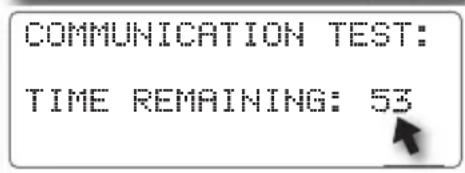
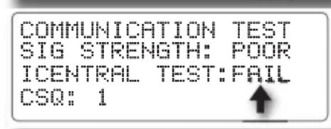
The straight-forward communication setup options include: Enable, Disable, and Test. The communications test checks signal strength and two-way communications with the iCentral. The 60-second test is monitored as it progresses. When testing has concluded, the relative signal strength is rated as: Excellent, Good, Fair, Poor, or None. In addition, a CSQ value from 0–32 is provided.
- Press the SETUP key to display the SETUP menu. Turn the Dial to choose COMM.
- Press the Dial to display the SETUP COMMUNICATION screen. The ENABLED option is chosen by default.
- Turn the Dial to select START, then press the Dial to initiate the test.
- The count-down screen will be displayed. • To terminate the test, press the BACK △ key. • The results will be displayed at the conclusion.
Note: If the signal strength is NONE or POOR, and/the or the CSQ number is low, and/or FAIL is indicated, contact Rain Master technical support at 1-800-777-1477 for recommended troubleshooting procedures.
![SETUP: -CONTROLLER- -FLOW- -PROGRAM- → [COMM] -ET- -TWO-WIRE-↑](/content/2026/05/1108149/images/c6a34de17a448106ffea9339294ba1588080418f9f671db4f8345378c852eecd.jpg)
![SETUP COMMUNICATION: COMM[ENABLED] COMM CARD: PRESENT COMM TEST-START- ↑](/content/2026/05/1108149/images/cd8f3bf7abde6834bf5c62530fda2fa2de9afb6dd9c47c0dee0ea8aa4692e0ca.jpg)
![SETUP COMMUNICATION: COMM-ENABLED - COMM CARD: PRESENT COMM TEST[START]← ↑](/content/2026/05/1108149/images/b522cd0166510c036ea65e159db52e277ef8ee5c968df086bb63ce4c2d6e5f96.jpg)

Two-Wire Decoder System Setup
When the Eagle Plus is equipped with the Two-Wire Decoder interface board, access to the Two-Wire setup menu options become available. The setup functions for the Two-Wire Decoder system include:
- Program Decoder – Provides Decoder programming and setup options.
• Show Stations – Retrieves and displays current station address information. - Test – Provides multiple test functions for Decoder station address verification.
Note: If the decoder board is not installed or a hardware malfunction has occurred, the prompt screen shown at right will be displayed.
SETUP TWO-WIRE TWO-WIRE BOARD NOT FUNCTIONING OR NOT PRESENT.
Programming the Decoders
Rain Master decoders are available in 1-, 2-, and 4-station output models, and as shipped from the factory, have no pre-defined station assignments. To be recognized by the Eagle Plus controller, each station must be addressed as either a station number from 0 – 200, a Master Valve, or a Pump control. To facilitate decoder programming, a quick-connect terminal block is provided on the Two-Wire Decoder board.
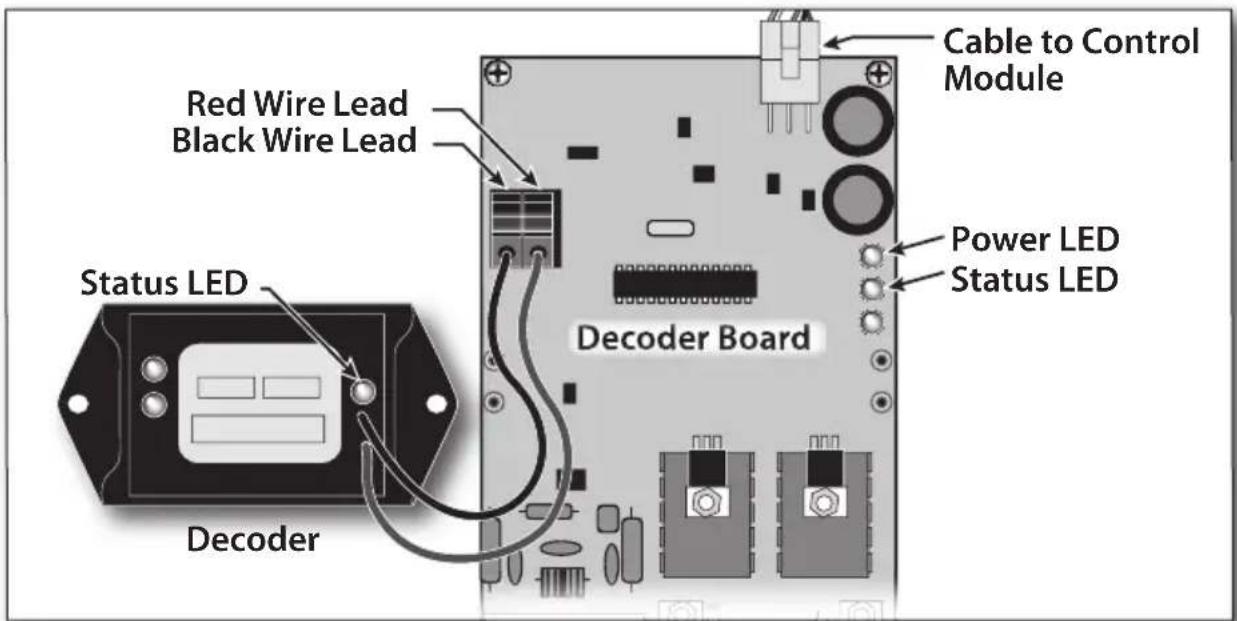
Note: The Eagle Plus enables the decoders to be temporarily connected and programmed without disconnecting power. Confirm the Power LED on the Decoder board is illuminated before continuing. If it is not illuminated, confirm that power is on and the Decoder board is properly connected to Control Module.
CAUTION: Red and Black decoder wires must be connected to the decoder board terminal block in the correct orientation. Damage to the decoder and/or controller may result from crossing the wire connection.
- Insert the red and black decoder leads into the corresponding quick-release terminal connectors as indicated below.
- Press the SETUP key to display the SETUP menu. The CONTROLLER menu item is chosen by default. Turn the Dial right five steps to choose the TWO-WIRE menu option, then press the Dial to select.
- The SETUP TWO-WIRE menu screen is displayed with PROGRAM DECODER option chosen by default. Press the Dial to select. Status LEDs on the Decoder Board and Decoder should begin blinking to confirm communication.
![SETUP: -CONTROLLER- -FLOW- -PROGRAM- -COMM- -ET- → [TWO-WIRE] ↑](/content/2026/05/1108149/images/86d922f1ff4d6f5707436ae2319342f12b459cf31e35c91b21004442ee0b798f.jpg)
![SETUP TWO-WIRE [PROGRAM DECODER] -SHOW STATIONS-- -TEST-](/content/2026/05/1108149/images/40422e13a8cee0ee657e6fffa3a5a13e935a23b3e1e3f3c2a83a8e8a104b3028.jpg)
Note: If the Decoder Status LED does not illuminate periodically, confirm the red and black lead wires are properly connected to the terminal block. A faulty decoder is indicated if the Status LED does not illuminate.
- The PROGRAM DECODER screen is displayed with the NEW ADDRESS option chosen.
Note: In this example, NONE indicates that decoder station slot 1 (of 4 available slots) has no programmed address. - To select a different decoder station slot number, turn the Dial to choose the slot number, then press the Dial to select. Turn the Dial to display the preferred number, then press the Dial to enter the selection.
- Press the Dial to choose NEW ADDRESS. Turn the Dial to display the preferred address (001–200, MV, PMP or NONE), then press the Dial to enter. In this example, station number 12 will be assigned to decoder station slot 2 of 4.
- Turn the Dial to choose PROGRAM, then press the Dial to begin the procedure. Within a few moments the results will be displayed. If programming was successful, OK will be momentarily displayed in the upper right corner, and the next decoder station number in sequence will be displayed. If programming was not successful, FAIL will be displayed and an Alarm will be generated.
![PROGRAM DECODER: CURRENT ADDRESS: NONE NEW ADDRESS[NONE] 1- OF 4 -PROGRAM- ↑](/content/2026/05/1108149/images/2535d4d68271f9215c9859c1c0b734cafcca447896b9ee400c797cfb0620abc4.jpg)
![PROGRAM DECODER: CURRENT ADDRESS: NONE NEW ADDRESS[NONE] 2] OF 4 -PROGRAM- ↑](/content/2026/05/1108149/images/5392ee8fc5d745f329a188ea17d13789c4a3cbc869329d077b4330019dc9afd2.jpg)
![PROGRAM DECODER: CURRENT ADDRESS:NONE NEW ADDRESS[012] -2- OF 4 -PROGRAM- ↑](/content/2026/05/1108149/images/8f469fd05b8372a38e2ca6f5e1754ba113654310ed099650bf466b43790ab32e.jpg)
![PROGRAM DECODER: CURRENT ADDRESS:NONE NEW ADDRESS-012- -2- OF 4 [PROGRAM]](/content/2026/05/1108149/images/3b72d3c03585b9946ccb49cf8997b26592e99306a752d590c563d0eb0ebb24e7.jpg)
![PROGRAM DECODER: OK CURRENT ADDRESS: FAIL NEW ADDRESS-012- -3- OF 4 [PROGRAM] ↑](/content/2026/05/1108149/images/d5f90dfbc361e848b250fbf11346b5a1660c41846404fcbe282e8b9d10f93a5f.jpg)
Note: To clear the Alarm, refer to Resolving Alarms, page 52.
- Repeat the programming procedure for all decoder stations as required.
Testing the Two-Wire Decoder System
The Two-Wire Decoder system test feature provides methods of testir decoder installation to easily verify communication, station assignment and operating status and log the results. The following test options are
- Single Station: Tests a selected Decoder station number.
• Find Decoders: Searches communication path for all responding De - All Programmed: Tests all decoder stations (1–200, Master Valve o have been defined within a program.
• All Stations: Tests all decoder stations, Master Valve and Pump c - Alarm Logging Options: Test results can be logged as Alarms in and/or Fail as selected.
- Log Fail Alarm: When selected, a decoder station that fails the will be logged.
- Log Pass Alarm: When selected, a decoder station that passes 1 criteria will be logged
Single Station Test
- Press the SETUP key to display the SETUP menu. Turn the Dial to choose the TWO-WIRE option, then press the Dial to select.
- The SETUP TWO-WIRE menu screen is displayed with the PROGRAM DECODER option chosen by default. Turn the Dial to choose the TEST option, then press the Dial to select.
- The SETUP TWO-WIRE TEST screen is dis with SINGLE STATION test type chosen by default.
- Turn the Dial to choose the LOG FAIL option. To change the current setting, press the Dial to select, then turn the Dial to a preference. Repeat this procedure for the PASS option as preferred.
- Turn the Dial to choose GO, then press the Dial to continue.
![SETUP: -CONTROLLER-- -FLOW-- -PROGRAM-- -COMM-- -ET- → [TWO-WIRE]↑](/content/2026/05/1108149/images/043e956f15022e93fddb882f84c957089bed8cf866998eebd951bea0959a6cde.jpg)
![SETUP TWO-WIRE -PROGRAM DECODER- -SHOW STATIONS- [TEST]](/content/2026/05/1108149/images/589b2efe7a578f22b7bac066e57e15bf51e258463608cdf0f0d14c99315cc6ed.jpg)
![playedP TWO-WIRE TEST TYPE[SINGLE STATION] LOG FAILURES-YES- LOG PASS-YES- -GO-↑](/content/2026/05/1108149/images/c4cb90e6a349edd778460c5aca5bfef02d7fe5f5407f4cc5deb6d017bcc86c7c.jpg)
![LURES SETUP TWO-WIRE TEST TYPE-SINGLE STATION- LOG FAILURES[NO 1←] display the LOG PASS-YES-- -GO-↑ the LOG](/content/2026/05/1108149/images/071645c939223b8758cfc7a59c5306b6997243ba8b59ac5ac24c1c5f414d3d18.jpg)
![SETUP TWO-WIRE TEST TYPE-SINGLE STATION-- LOG FAILURES-NO - LOG PASS-YES-→[GO]↑](/content/2026/05/1108149/images/8d50c853848104992d1a09e9015ae0cc20302f808d6e1a6fcaae228bc18f5200.jpg)
-
The SINGLE STATION TEST screen will be displayed with STATION 1 chosen by default. To change the station selection, press the Dial to select, turn the Dial to display the preferred station number, then press the Dial to enter.
-
Turn the Dial to choose GO, then press the Dial to start the test.
Note: The test will take approximately 3 minutes.
- The test results will be displayed. Alarm Log options selected, an alarm may be generated.
Note: To pause or stop the test, turn the Dial to choose STOP, then press the Dial to pause the test. To resume the test, press the Dial again. To terminate the test, press the BACKkey.
-
Press the HOME key to return to the Home screen. Turn the Dial to choose ALARMS, then press the Dial to review the Alarm screen.
-
Turn the Dial to choose CLEAR, then press the Dial to clear the alarm.
Note: Clearing alarms removes the screen prompts and turns off the Alarm LED indicator. Logged alarm information is accessed from the REVIEW menu screen.
![SINGLE STATION TEST STATION[ 1] -GO-↑](/content/2026/05/1108149/images/d47cdfc24df004aefab5eef514085e6864cc584f91f11e5e32335f70d93cab04.jpg)
![SINGLE STATION TEST STATION- 1- →[60]↑](/content/2026/05/1108149/images/e175c6b61a57a40e6bf05c3369bf7f3a9566e7732a89d3b489aa4135310f2590.jpg)
![Based on the SETUP TWO-WIRE TEST: TESTING STATION: 12 TESTING CURRENT: .18 VERSION: 0 →[STOP]↑](/content/2026/05/1108149/images/a0db75da291e7aa808194d3f49165e116df543a3deacb2042888347e4b33b96b.jpg)
![WE 02:47:41P WK1 ?..II VALID PGM:NONE -MAIN-[ALARMS( 1)]](/content/2026/05/1108149/images/39cdc058d100d2868280ce71b300ea68a9e1d51a011f4cacb6a792a0edc8bb4e.jpg)
![06/16 WE 02:48:01P STATION 12 DECODER FOUND [CLEAR] ↑](/content/2026/05/1108149/images/8853a59b7844fecad4cc0627c43c10dc482ee9c35d172d3b2ef0dc72955568c3.jpg)
Find Decoders Test
-
Press the SETUP 📂 key to display the SETUP menu. Turn the Dial to choose the TWO-WIRE option, then press the Dial to select.
-
The SETUP TWO-WIRE menu screen is displayed with the PROGRAM DECODER option chosen by default. Turn the Dial to choose TEST, then press the Dial to select.
-
The SETUP TWO-WIRE TEST screen is dis with SINGLE STATION test type chosen by default. Press the Dial to select, then turn the Dial to display FIND DECODERS.
![SETUP: -CONTROLLER- -FLOW- -PROGRAM- -COMM- -ET- [TWO-WIRE]↑](/content/2026/05/1108149/images/89bb33e0108eca15961626bc4292f39225da5d8dd6045ba33f22367d6d333eb9.jpg)
![SETUP TWO-WIRE -PROGRAM DECODER-- [SHOW STATIONS] -TEST-](/content/2026/05/1108149/images/4a3e75d8afd231ba6063cf103f5a74079ce3d5a67a8fa45f4c13a4327d508eac.jpg)
![SETUP TWO-WIRE TEST TYPE[FIND DECODERS] LOG FAILURES-YES-- LOG PASS-YES-- -GO-↑](/content/2026/05/1108149/images/89119df6191eb1561719bec896fbf2cc32598b7680013b343ba6e7d4981ac39f.jpg)
- Turn the Dial to choose the LOG FA option. To change the current setting, press the Dial to select, then turn the Dial to display the preference. Repeat this procedure for PASS option as preferred.
- Turn the Dial to choose GO, then press the Dial to begin the test.
Note: The test will take approximately 3 minutes.
- The test results will be displayed. Based on the Alarm Log options selected, an alarm generated.
Note: To pause or stop the test, turn the Dial to choose STOP, then press the Dial to pause the test. To resume the test, press the Dial again. To terminate the test, press the BACKkey.
![ILURES SETUP TWO-WIRE TEST TYPE-SINGLE STATION- LOG FAILURES[NO ] LOG PASS-YES- -GO-↑ the LOG](/content/2026/05/1108149/images/82462b847716d5f44b5116f89c9575ba5118bb861a0f82eaa693a5111be3a18a.jpg)
![SETUP TWO-WIRE TEST TYPE-SINGLE STATION- LOG FAILURES-NO - LOG PASS-YES->[GO]↑](/content/2026/05/1108149/images/4f1af7eba0d056a38a42a4113a3955919f40424f8d655b66243dd4d4cba80277.jpg)
![SETUP TWO-WIRE TEST: TESTING STATION: 12 TESTING CURRENT: .18 VERSION: 0 → [STOP]↑](/content/2026/05/1108149/images/4a3463170fd2102830b43ec33b8704077b0ae2bb2d508fd04c12990bdca10e43.jpg)
![WE 02:47:41P WK1 ?..! VALID PGM:NONE -MAIN-[ALARMS( 1)]](/content/2026/05/1108149/images/44ab9e311c676ae6e23281bf98f21ca9c94b533ab4f0efe884991046fcc0e841.jpg)
- Press the HOME 🔒 key to return to the Home screen. Turn the Dial to choose ALARMS, then press the Dial to review the Alarm screen.
All Stations Test
Note: To run the ALL STATIONS test, refer to the FIND DECODERS test procedure on the previous page. Select the ALL STATIONS option in lieu of FIND DECODERS in step 3.
Show Stations
- Press the SETUP key to display the SETUP menu. Turn the Dial to choose the TWO-WIRE option, then press the Dial to select.
- The SETUP TWO-WIRE menu screen is displayed with the PROGRAM DECODER option chosen by default. Turn the Dial to choose SHOW STATIONS, then press the Dial to begin.
Note: The test will take approximately 3 minutes.
- The controller will search for all stations assigned to any of the 16 watering programs. The results will be displayed on one or more sequential screens. Press the NEXT ▼ and BACK △ keys to access and review the screens.
![SETUP: -CONTROLLER-- -FLOW-- -PROGRAM-- -COMM-- -ET- →[TWO-WIRE]↑](/content/2026/05/1108149/images/0aafd0923c081e03b76f35b6b0bb4c727fecbb205e9b9dde923b65facf069acc.jpg)
![SETUP TWO-WIRE -PROGRAM DECODER- [SHOW STATIONS] -TEST-](/content/2026/05/1108149/images/49f03758d679a0674e0b9671bd840f29af9582d83bb846070f9b7baf3b769d76.jpg)

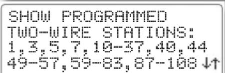
Programming for Automatic Operation
The Eagle Plus enables you to define up to 8 automatic programs for conventional control system, or up to 16 programs for a decoder system. A program is comprised of the following three primary operating parameters that must be established to create a valid program:
• An active day schedule
• A program start time
• A station run time.
The operating options selected within the various Setup menus are app the programs to further define and regulate controller operations.
IMPORTANT: A program becomes valid only after all three primary operating parameters have been entered. Once a valid program is entered, all user-defined program values will remain intact. Failing to enter all three parameters correctly, or prior to the display timing-out, will invalidate that program. It is recommended to always confirm the valid program status whenever creating or modifying programs.
Creating a New Program
Setting a Two-Week Watering Schedule
- Press the PROGRAM key to display the PROGRAM menu. The MODIFY menu item is chosen by default. Turn the Dial to choose the NEW option, then press the Dial to select.
- The NEW PROGRAM screen is displayed with the program number chosen by default. To change the program number assignment, press the Dial to select, then turn the Dial to change the program number. Press the Dial to enter the selection.
- Turn the Dial to choose CREATE PROGRAM, then press the Dial to select.
Note: If the program number selected is already an established (valid) program, a prompt screen will be displayed. Selecting YES will overwrite the existing program; selecting NO will leave the program unchanged. Repeat Step 2 and 3 to select an available program number, then continue to Step 4.
![PROGRAM: -MODIFY- [NEW] -REVIEW- -DELETE- -COPY-](/content/2026/05/1108149/images/ce4e93695989db21b05007fe965135717df6c2eae09a880a4abd500eda931940.jpg)
![NEW PROGRAM →[ 3] VALID PGM:1-3 -CREATE PROGRAM- ↑](/content/2026/05/1108149/images/13f1215aaec307c56160f62e7963d81fabd5fc87cdfd26a3907198893406307b.jpg)
![NEW PROGRAM - 3- VALID PGM:1-3 [CREATE PROGRAM]← ↑](/content/2026/05/1108149/images/a7c8d8d27a5c374145b6d5fa49e488daf9cb9e2be7510dc5ca94fd5189be6ada.jpg)
![ARE YOU SURE YOU WANT TO DELETE EXISTING PROGRAM 3? -YES-[NO]↑](/content/2026/05/1108149/images/d03d709dadebbefa34b1f28ecd1d03f6b02021ec14339bf63a8685757c8affbc.jpg)
- The two-week schedule screen is displayed with S (Sunday) of W1 (Week 1) chosen by default.
- To select the day, press the Dial (an X will appear), or to skip the day, turn the Dial to the preferred day, then press the Dial to select.
Note: Pressing the Dial repeatedly toggles the selection ON and OFF.
- Continue to define the remaining days of the two-week schedule in this manner.
Note: The asterisk next to W1 or W2 indicates the current week of the two-week watering cycle and is not pertinent to the programming procedure.
- When the two-week schedule is set, select OK, or press the NEXT ▼ key to display the START TIME setup screen.
![NEW PROGRAM:1 S M T W T F S [ ]← W1* W2 ↓↑](/content/2026/05/1108149/images/bb1c9a646579cb494dd03b19360aad8aab4decf583f5469d7af5fab49ec0f264.jpg)
![NEW PROGRAM:1 -OK- SMTWTS [×]← W1* W2 ↓↑](/content/2026/05/1108149/images/e30f9481741814790eff2a3e19bf4fd2123c6f450778aa9b191946266a980d16.jpg)
![NEW PROGRAM: 1 [OK] S M T W T F S × × W1* × × × W2 ↓↑](/content/2026/05/1108149/images/8a7b62fabc46032384618e1f54f3609a20b99918fdb9994806857da551e67605.jpg)
![NEW PROGRAM:1→[OK] S M T W T F S × × W1* × × × W2 ↓↑](/content/2026/05/1108149/images/ba485991bcfe4ba65b34a22fe4fe8fe3cd7ce28b4bda45f1c528fb89b6ea3772.jpg)
Setting a Skip-Day Watering Schedule
Note: The Skip Days scheduling option will not be available for the selected program unless it is initially assigned to the program within the Program Setup menu>Type options. See page 20 for Skip Day information and setup procedures.
- Turn the Dial to choose the SKIP DAYS value. Press the Dial to select, then turn the Dial to display the number of days between active watering days (0–30). Press the Dial to enter.
Note: To water every day, select 0. To water every-other-day, select 1, etc.
- Turn the Dial to choose the START delay value. Press the Dial to select, then turn the Dial to display the number of days before starting the skip day cycle (0–30). Press the Dial to enter.
Note: To start the watering day cycle today select 0; to start tomorrow select 1, etc.
- When the SKIP DAY setup values are set, select OK, or press the NEXT ▼ key to display the START TIME setup screen.
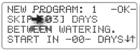
![NEW PROGRAM: 1 -OK- SKIP -03- DAYS BETWEEN WATERING. START IN★02] DAYS↓↑](/content/2026/05/1108149/images/43a92412c8fe979a6d27f460e627b598de76692f29e2424b7fe279e5859c6c37.jpg)
![NEW PROGRAM: 1→[OK] SKIP -03- DAYS BETWEEN WATERING. START IN -02- DAYS↓↑](/content/2026/05/1108149/images/b16c1237e62a04841741dc297a300a7cf4e0d762098fc9d7ce45f64213db5953.jpg)
Setting Program Start Times
- Each program can have up to 8 start time assignments. START TIME 1 is selected by default.
- Turn the Dial to choose HH:MM. The start time will default to 12:00AM with the hour digits selected (blinking).
- Turn the Dial to set the start time hour, then press the Dial to enter. The minutes digits will begin blinking. Set the start time minutes and AM/PM designator in the same manner.
- START TIME 2 is prompted as START TIME 1 is entered. Continue to assign up to 8 start times for this program as preferred.
- When finished, choose and select OK, or press the NEXT ▼ key to display the STATION RUN TIME setup screen.
![NEW PROGRAM: 1 TOTAL START TIMES:1 START TIME[1] -HH:MM - -DELETE-↓↑](/content/2026/05/1108149/images/53a02d1ab4dd30188d63fbcbdeaa32c652a7772316d6ea1128a9c8326ae5ca99.jpg)
![NEW PROGRAM: 1 TOTAL START TIMES:0 START TIME-1- [12:00AM]←DELETE-↓↑](/content/2026/05/1108149/images/b29cf5a34c7b2bcdce72f1a06adc006e68cd8995392460d6797f8fff046b7d83.jpg)
![NEW PROGRAM: 1 -OK- TOTAL START TIMES:0 START TIME-1- [ 6:15AM]←DELETE-↓↑](/content/2026/05/1108149/images/567a8cdd9b9a9c34228955e7684ef07de494978f1c1b99a61d35b23509ba99d5.jpg)
![NEW PROGRAM: 1 -OK- TOTAL START TIMES:1 START TIME-2- [HH:MM]←DELETE-↓↑](/content/2026/05/1108149/images/e35a3efd2f2377d65927a8d54d541d0df2a68f2c552dc21fe68cea69306da69f.jpg)
Note: To clear the displayed start time, choose and select the DELETE option.
Assigning the Station Run Time
Note: If the CYCLE AND SOAK option was selected for the program, continue at Setting a Cycle and Soak Station Run Time on the next page.
- STATION 1 is selected by default. To change the station number, press the Dial to select. Turn the Dial to display the preferred station number, then press the Dial to enter the selection.
- Turn the Dial to choose the station run time value, then press the Dial to select. The hours digit is selected and will begin blinking.
- Turn the Dial to display the preferred run time hours (0–23), then press the Dial to enter. The minutes digits will be selected. Turn the Dial to select the run time minutes (0–59), then press the Dial to enter.
- The next station number in sequence will be prompted. Continue to assign additional stations to this program as preferred.
![NEW PROGRAM: 1 STATION [ 1]← RUNTIME-00:00- ↓↑](/content/2026/05/1108149/images/f914b16a95cf310fb37c13f97a29bf178e264ede23a56ca1238ae6d3d88c6989.jpg)
![NEW PROGRAM: 1 STATION - 1- RUNTIME[ 0:00]← ↓↑](/content/2026/05/1108149/images/fd774939f08f6052df991d4ece60e99cd03d26ee57032b4bebcf6049621b55dc.jpg)
![NEW PROGRAM: 1 STATION- 1- RUNTIME[ 1:15]← ↓↑](/content/2026/05/1108149/images/2b307c46f3135766552eaa8b4d8f6ffc849fae7755187d441c01e5abc25ddd50.jpg)
![NEW PROGRAM: 1 [OK] STATION- 2- RUNTIME-00:00- ↓↑](/content/2026/05/1108149/images/94523f943753d5cb150f4bf20cd8ec0ee23dc42686495dbb46c75e67f1b7b62b.jpg)
- Press the NEXT ▼ key to display the PROGRAM summary screen.
Note: If the program is not valid, press the BACKkey to recall, correct, and/or adjust the various program setup parameters as necessary. When the summary screen indicates that the program is valid, choose and select OK.
![PROGRAM: 1 NOT VALID TOTAL RUNTIME:00:00 [OK] ↑](/content/2026/05/1108149/images/06fd5cfa9861af4ff453ba0874e1c965d8835ef9d8032dd52584871792f23757.jpg)
![PROGRAM: 1 IS VALID TOTAL RUNTIME:06:45 →[OK] ↑](/content/2026/05/1108149/images/88a7da71fafe68e8a9d77a32354f1a90f8e687b530b9ce225243965df193e388.jpg)
Setting a Cycle and Soak Station Run Time
Note: The Cycle and Soak scheduling option will not be available for the selected program unless it is initially assigned to the program within the PROGRAM SETUP> TYPE menu. See page 20 for the Cycle and Soak setup procedure.
- Station 1 is selected by default. To change the station number, press the Dial to select. Turn the Dial to display the preferred station number, then press the Dial to select.
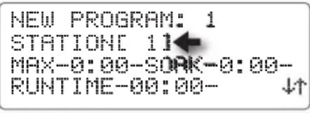
Important: Any station assigned to the program with a 0:00 MAX or SOAK time value will not operate during the program watering cycle.
-
Turn the Dial to choose the MAX run time value, then press the Dial to select. The hour digit is selected and will begin blinking. Turn the Dial to display the run time (0–9 hours), then press the Dial to select.
-
The minutes digits will be selected (blinking). Turn the Dial to select the run time minutes (0–59), then press the Dial to enter.
-
Turn the Dial to choose the SOAK time value, then press the Dial to select. The hour digit is selected and will begin blinking. Turn the Dial to display the soak time (0–9 hours), then press the Dial to select.
-
The minutes digits will be selected. Turn the Dial to select the RUN TIME minutes (0–59), then press the Dial to enter.
![NEW PROGRAM: 1 STATION- 1- MAX[1:00]SOAK-0:00- RUNTIME-00:00- ↓↑](/content/2026/05/1108149/images/a5efff388607beeb223df4f8166e1653c9a5df3d2f87ced2f213deb2f6f3d2e9.jpg)
![NEW PROGRAM: 1 STATION↓ 1- MAX[1:05]SOAK-0:00- RUNTIME-00:00- ↓↑](/content/2026/05/1108149/images/991bd015e4e1497a53c6492f309379e3ca88c449d6e22a83b3e45c4dd52ece9b.jpg)
![NEW PROGRAM: 1 STATION- 1- MAX-1:05-SOAK[2:00] RUNTIME-00:00- ↓↑](/content/2026/05/1108149/images/3a5c596dbc94ebc16515da0ce1876a1b5999b46a574b8f161529aa9d6e5a8870.jpg)
![NEW PROGRAM: 1 STATION- 1- MAX-1:05-SOAK[2:30] RUNTIME-00:00- ↓↑](/content/2026/05/1108149/images/a6ba467161b437b2460a3df601af8fe1dd3f6e6ea893f1eef2b80984f18108bf.jpg)
-
Turn the Dial to choose the RUN TIME value, then press the Dial to select. The hours digits are selected and will begin blinking. Turn the Dial to display the run time (0–23 hours), then press the Dial to enter. The minutes digits will be selected.
-
Turn the Dial to select the RUN TIME minutes (0–59), then press the Dial to enter the selection.
-
The next station number in sequence will be prompted. Continue to assign additional stations to this program as preferred. When finished, choose and select OK, or press the NEXT ▼ key to display the PROGRAM summary screen.
Note: The Program summary screen enables you to quickly verify the status and total run time of the program. If the program is not valid, press the BACK key to recall, correct and/or adjust the various program setup parameters as necessary.
![NEW PROGRAM: 1 STATION- 1- MAX-1:05-30AK-2:30- RUNTIME[00:00] ↓↑](/content/2026/05/1108149/images/4d746122d0720035c7b2ef0579844e7c598063d52c3f21541fe7c02d9e74be6f.jpg)
![NEW PROGRAM: 1 STATION- 1- MAX-1:05-SO4-2:30- RUNTIME[04:50] ↓↑](/content/2026/05/1108149/images/4aeae84449a3c3d321296a73a44177bbf2727404f13f8ad924c645519d1e308b.jpg)
![NEW PROGRAM: 1 -OK- STATION- 2 MAX-0:00-SOAK-0:00- RUNTIME[00:00] ↓↑](/content/2026/05/1108149/images/0fdaa409498c0e5f95db391bac4cb419eabc449bc7887a38676fcbf62635820c.jpg)
![PROGRAM: 1 NOT VALID TOTAL RUNTIME: 00:00 [OK] ↑](/content/2026/05/1108149/images/cc7ffa419e29c5d34fc198ddfff5bca37aef81fac37348d02cf24b6b16824b44.jpg)
![PROGRAM: 1 IS VALID TOTAL RUNTIME:06:45 →[OK] ↑](/content/2026/05/1108149/images/10e48c4d4fe06ef7f14c40aa7e20634d1c226c91c242f674b81db0d1292a993f.jpg)
- When finished, choose and select OK to complete the setup requirements for the selected program.
Modifying a Program
The Modify Program feature provides a convenient way to access and adjust any parameter of an established program including:
- Days – Two-Week and Skip Days schedules
- Runtime – Station run time assignment
- Start – Start time assignments
-
Percent – Run Time adjustment by percentage for all assigned stations.
-
Press the PROGRAM ☐ key to display the PROGRAM menu. The MODIFY menu item is chosen by default. Press the Dial to select.
-
The program number is chosen by default. To change the program number assignment, press the Dial to select, then turn the Dial to display the preferred number. Press the Dial to enter the selection.
- Turn the Dial to choose a portion of the program to be modified. Press the Dial to display the initial modification screen.
![PROGRAM: [MODIFY]←-NEW-- -REVIEW- -DELETE-- -COPY- ↑](/content/2026/05/1108149/images/4bdb94aaec6dcb581d0fc7c40c8b79fca56f3b0182ae11ceb13487072a2aeadc.jpg)
![MODIFY PROGRAM[1] -DAYS- -RUNTIME- -START- -PERCENT-](/content/2026/05/1108149/images/733665c6fd514b57dce48881eb33c2f105787d620334258e75d9b241642d6706.jpg)
![MODIFY PROGRAM-1- [DOYS]← -RUNTIME-- -START- -PERCENT-](/content/2026/05/1108149/images/14e5bbb25c6fb0b52771c62bd38d2479262dac60fb56d08e9897fcc36473ecf6.jpg)
Note: The PROGRAM setup options defined for DAYS, STATION RUN TIMES and START TIMES are utilized for the modification procedures. To assist in the modification process, refer to the corresponding PROGRAM SETUP procedures, beginning on page 36
Adjusting Program Percent Value
To account for changes in season or weather, the total operating duration for any established program cycle time can be easily increased or decreased by a percentage factor from 0%–300%, in 1% increments. The run time for each station assigned to the program will be modified by the percentage change.
IMPORTANT: Increasing the program cycle duration can result in a conflict with other scheduled watering programs and/or the defined Water Window duration. The recommended method of increasing run time by percentage is to make small, incremental changes while monitoring the results over a period of time.
- From the MODIFY PROGRAM menu screen, turn the Dial to choose PERCENT, then press the Dial to select.
- Turn the Dial to choose the PERCENT value. Press the Dial to select, then turn the Dial to display the preferred percent value (0–300). Press the Dial to enter the selection.
- Repeat procedure for each program as needed.
![MODIFY PROGRAM-1- -DAYS- -RUNTIME- -START- →[PERCENT]](/content/2026/05/1108149/images/2f8134fca868bd2b71f4cfebf9f59c0093e1e3e41babebb3e8fec163605c1e83.jpg)
![MODIFY PROGRAM- 1- PERCENT[100]](/content/2026/05/1108149/images/eaf535c173b668b466c1980c34265e2e82a687b3e32f15b583d141ab2c0bed37.jpg)
Deleting a Program
The Delete Program feature provides a convenient method of accessing and clearing all established operating parameters from a specified program.
- Press the PROGRAM key to display the PROGRAM menu. Turn the Dial to choose the DELETE option, then press the Dial to select.
- Turn the Dial to choose the PROGRAM number. Press the Dial to select, then turn the Dial to display the PROGRAM number to delete. Press the Dial to enter the selection.
- A decision screen will be prompted with the YES option chosen. To complete the Delete function, press the Dial to enter YES. To abort the Delete function and return to the previous screen, choose and select the NO option.
![PROGRAM: -MODIFY-- -NEW- -REVIEW- [DELETE] -COPY-](/content/2026/05/1108149/images/e3008ad6f3e516a8a2abc07c6c3f81e00e103586567bdab56facc0b00d58f25d.jpg)
![DELETE PROGRAM[ 1]? TOTAL STATIONS: ↑6 TOTAL START TIMES:3 -YES- -NO- ↑](/content/2026/05/1108149/images/4ed7a6952a0fe18ff83ea4a3d33dc11b91633f9e14e17f3fe3a16ae7b7826160.jpg)
![ARE YOU SURE YOU WANT TO DELETE PROGRAM 1? [YES] -NO- ↑](/content/2026/05/1108149/images/bf1e9f5153e329bf52c74a098e42ebf4be1741240c2b7ef7a13c37cf569bfc4d.jpg)
Copying a Program or Runtime
The Copy function provides a convenient method of transferring all program setup parameters* from one program to another, or to apply a specific station run time to multiple stations. When setting up multiple programs with similar attributes, the copy functions will not only reduce the setup time by eliminating redundant tasks, but will help ensure consistency throughout the overall watering program setup structure.
*Note: Program attributes include: watering day schedule, station run time, cycle and soak time, start times and percent adjust factor.
To Copy a Program:
- Press the PROGRAM key to display the PROGRAM menu. Turn the Dial to choose the COPY option, then press the Dial to select.
- Turn the Dial to choose the Copy Program option, then press the Dial to select.
- Press the Dial to choose the COPY PROGRAM number. Press to select, then turn the Dial to display the PROGRAM number to be copied from. Press the Dial to enter the selection.
- Turn the Dial to choose the TO PROGRAM number. Press to select, then turn the Dial to display the recipient program number. Press the Dial to enter the selection.
- Turn the Dial to choose OK, then press the Dial to enter the selection.
Note: A decision screen will be prompted with the OK option chosen by default.
To complete the Copy function, press the Dial to begin the Copy function. To abort the Copy function and return to the previous screen, choose and select the CANCEL option.
- Upon completion of the copy function, the initial COPY FUNCTION screen will be displayed. Repeat the procedure for additional programs as preferred.
![PROGRAM: -MODIFY- -NEW- -REVIEW- -DELETE- [COPY]↑](/content/2026/05/1108149/images/13183c9a0a525e83a9d856b89fc7bc7a080e9263fb78edaf8856cee351b333de.jpg)
![COPY FUNCTION: [COPY PROGRAM] -COPY RUNTIME-](/content/2026/05/1108149/images/df406eeb7e127118b12b444f3bbca7df091c8736012200cca7d781d01576885f.jpg)
![COPY PROGRAM[ 1] TO PROGRAM- ↑ -OK- ↑](/content/2026/05/1108149/images/8526fc110ad4e9845a60655b5d8efcc61a8c930aeee1d24307d25a7c61b80a02.jpg)
![COPY PROGRAM- 1- TO PROGRAM[ 2] -OK- ↑](/content/2026/05/1108149/images/28f138e1a41ee421ed52f318eaeb08ecc3940ffbd0a8c06124846e374f0797dd.jpg)
![COPY PROGRAM- 1- TO PROGRAM[ 21 [OK]← ↑](/content/2026/05/1108149/images/0721d90c6b382595d2dd30749c64dc40768711d9d7ce4b4352dbdcd2ef5d9df5.jpg)
![WARNING:PROGRAM 2 WILL BE OVERWRITTEN →[OK] -CANCEL- ↑](/content/2026/05/1108149/images/0b67866010d6c1549083eef64f5cc5a9189d8fde255ee7f0e32a89750d3fc1fc.jpg)
![COPY FUNCTION: [COPY PROGRAM] [COPY RUNTIME]](/content/2026/05/1108149/images/e46f6d500b62238d07a805a46a5d67c113be18063a06cc4bf509cd880fa0a51f.jpg)
To Copy a Run Time:
- Press the PROGRAM key to display the PROGRAM menu. Turn the Dial to choose the COPY option, then press the Dial to select.
- Turn the Dial to choose the COPY RUNTIME option, then press the Dial to select.
- The COPY RUN TIME screen is displayed with the run time value chosen. Press the Dial to select, then turn the Dial to display the preferred run time hours (0–23). Repeat to select the run time minutes (0–59).
- Turn the Dial to choose TO PROGRAM. Press the Dial to select, then turn the Dial to display the recipient program number. Press the Dial to enter the selection.
Note: All station numbers, inclusive from the BEGIN and END station numbers entered, will receive the specified run time assignment.
- Turn the Dial to choose BEGIN STATION. Press the Dial to select, then turn the Dial to display the preferred beginning station number. Press the Dial to enter the selection.
- Turn the Dial to choose END STATION. Press the Dial to select, then turn the Dial to display the preferred station number. Press the Dial to enter the selection.
- Turn the Dial to choose OK, then press Dial to begin the Copy function.
- Upon completion of the copy function, the initial COPY FUNCTION screen will be displayed. Repeat the procedure for additional programs as preferred.
![PROGRAM: -MODIFY- -NEW- -REVIEW- -DELETE- [COPY]↑](/content/2026/05/1108149/images/686d0fdd336dffc59523670a220e82c8c6fd3d1f9a105db9269fd440b89ee76e.jpg)
![COPY FUNCTION: [COPY PROGRAM] [COPY RUNTIME]](/content/2026/05/1108149/images/8229590cd70027e86ad72a22bf79dc65a22561455e532119403a67a8f7278549.jpg)
![COPY RUNTIME[00:15] TO PROGRAM- 1- BEGIN STATION- END STATION- 1-OK-↑](/content/2026/05/1108149/images/eaa9d9d268033dd7f49c8e5c18c4569ece01d06490f6f6ccbeaafada973812a9.jpg)
![COPY RUNTIME-00:15- TO PROGRAM[ 1]← BEGIN STATION- 1- END STATION- 1-OK-↑](/content/2026/05/1108149/images/b9fe6ec4fe624dab114c56c3a8352125b86a9ede5cf85f6c0a6fc08e8c8c5c2c.jpg)
![COPY RUNTIME-00:15- TO PROGRAM- 1- BEGIN STATION[ 9] END STATION- 1-OK-↑](/content/2026/05/1108149/images/9007c098c6bb63b81b990ec9b85027c0d462766a58cf153e710382a1885b5f51.jpg)
![COPY RUNTIME-00:15- TO PROGRAM- 1- BEGIN STATION- 9- END STATION[ 18]←→↑](/content/2026/05/1108149/images/6327efa1453823098d85ed90f488e210ecd8aed7e523040d6f1d5a480c2eb944.jpg)
![COPY RUNTIME-00:15- TO PROGRAM- 1- BEGIN STATION- 9 END STATION- 18[OK]↑](/content/2026/05/1108149/images/12ca182c61067abc29a2936b223925577216f14d858bc3813c01756bbd5aee72.jpg)
![COPY FUNCTION: [COPY PROGRAM] [COPY RUNTIME]](/content/2026/05/1108149/images/53e719fa7a7b8cd03d759de5d41722aef4c5f330939e6a9a638b5ca85ab0bcd3.jpg)
Review Mode
The Review mode feature provides a convenient method of accessing all current controller program structure information, as well as historical records of prior irrigation activity, flow rates and ET values and wireless communications activity.
The REVIEW menu options include direct Program setup parameters, historical data logs for Irrigation activity, Alarm events, Flow rates, ET values, iCentral Communication protocol data and S/W (controller configuration).
Note: All information displayed on the Review screens is provided for reference and evaluation only. No changes or deletions to programming, operating, configuration or Alarm events can be made while the controller is in the Review mode.
Program Review
The Program review screens, accessible from both the PROGRAM and menus, access the following information for each irrigation program:
• Total program run time duration
• Program run time Adjust % factor
• Active watering day schedule
• Total assigned start times
• Total assigned station numbers
- Individual station run time assignment
• Cycle and Soak duration time (when applicable)
- Press the REVIEW ☐ key to display the REVIEW menu. The PROGRAM option is chosen by default.
![PROGRAM: -MODIFY- -NEW- [REVIEW]←-DELETE- -COPY- ↑](/content/2026/05/1108149/images/3f17c249aa95d0c570d286e366ecdcb8262534904b37f832129eaf59bfc022db.jpg)
- Press the Dial to select. The REVIEW PROGRAM screen is displayed with the PROGRAM number chosen. Press the Dial to select, then turn the Dial to display the preferred program number. Press the Dial to enter the selection.
![REVIEW: [PROGRAM]← -ALARM- -IRRIGATION- -FLOW- -COMM- -ET- -S/W- ↑](/content/2026/05/1108149/images/0bb86d71936265f724dc76d9a0fed32e00dcb24fee980f8626c0e44ebceb4d3f.jpg)
- Press the NEXT▼ and Back keys to navigate through the sequence of PROGRAM REVIEW screens.
Note: The PROGRAM number option is provided on the top line of each review screen to access information for any program as preferred.
![REVIEW PROGRAM[ 1] TOTAL STATIONS: 7 TOTAL RUNTIME: 2 HRS 24 MINUTES ↓↑](/content/2026/05/1108149/images/4057e854f2fee346ffe405455d1839e42e6bf482ce64031e1cdf578f5351bcd8.jpg)
Alarm Review
The alarm event archive will retain a maximum of 220 records. All alarm events are stored in chronological first-in, first-out order. When the archive reaches capacity, the oldest event record drops off as a new record enters.
-
Press the REVIEW key to display the REVIEW menu. The PROGRAM option is chosen by default. Turn the Dial to choose ALARM, then press the Dial to select.
-
The alarm archive screen will be displayed with a summary the last Alarm event. Press the NEXT and BACK keys to navigate through the sequence of review screens.
![REVIEW: -PROGRAM- →[ALARM] -IRRIGATION- -FLOW- -COMM- -ET- -S/W- ↑](/content/2026/05/1108149/images/beb28b4552e9226fdcd7d4fa9aa766e8d80abde308fdfb44e1dcec41ad34117f.jpg)

Communication Review Screens
Note: COMM review information (listed on four consecutive screens) provides comprehensive technical data pertaining to wireless communications configuration and activity.
-
Press the REVIEW key to display the REVIEW menu. The PROGRAM option is chosen by default. Turn the Dial to choose COMM, then press the Dial to select.
-
Press the NEXT ▼ key to access the remaining review screen sequence.
![REVIEW: -PROGRAM- -ALARM- -IRRIGATION- -FLOW- [COMM]←-ET- -S/W- ↑](/content/2026/05/1108149/images/cfc099a920447ac6bb55a02e76b51b284313e4fe99bf4a9f07348a6297158780.jpg)
![REVIEW COMM S8901260580015370817 MDM S/N:50399736 →[MORE]↓↑](/content/2026/05/1108149/images/3a3cff901f342ca3998acc8de1adc7927ecfd398cdd649a2f927a56085e3a2a9.jpg)
Flow Review
The Flow data archive retains up to 12 months of data records and compiled for review by month. The first of two review screens provides the selections for month and display units, with the total flow represented for each of two flow sensors. The second screen displays the sum total for both flow sensors.
-
Press the REVIEW key to display the REVIEW menu. The PROGRAM option is chosen by default. Turn the Dial to choose FLOW, then press the Dial to enter the selection.
-
The initial REVIEW FLOW screen is displayed with flow data for the current month. To change the month, press the Dial to select, then turn the Dial to display the preferred month. Press the Dial to enter the selection.
-
To use alternate display UNITS, turn the Dial to choose UNITS. Press the Dial to select, then turn the Dial to display the preference. Press the Dial to enter the selection.
![REVIEW: -PROGRAM- -ALARM- -IRRIGATION→[FLOW] -COMM- -ET- -S/W- ↑](/content/2026/05/1108149/images/b366471ea21ae5de31d0ab92fdf2f87002fc8b179a62832f6711441315bf0cdf.jpg)
![REVIEW FLOW:[JUN] UNITS-GALLONS - FLOW1=XXXXXXXX FLOW2=XXXXXXXX](/content/2026/05/1108149/images/48fb0066c2585a1590286d94f0c1d540f639efe57af17fd613d2795d72418a85.jpg)
![REVIEW FLOW: -JUN- UNITS[GALLONS] FLOW1=XXXXXXXX FLOW2=XXXXXXXX](/content/2026/05/1108149/images/e07acc2dc32b86a7a618244beb3b02d90ef3ec67a9f97af4b09d9018e73ed7b3.jpg)
- Press the NEXT key access the second review
screen displaying the flow data total for both sensors (if applicable). The same preference options for MONTH and UNITS are provided.
Irrigation Review
A record of the last 25 automatic irrigation programs are stored in chronological order with the latest event displayed first. When the archive reaches capacity, the earliest event record is deleted as a new event is recorded.
- Press the REVIEW key to display the
REVIEW menu. The PROGRAM option is chosen by default. Turn the Dial to choose IRRIGATION, then press the Dial to select.
- A summary of the most recent operation is
displayed. Press the NEXT ▼ and BACK △
keys to navigate through the review screens.
![REVIEW: -PROGRAM- -ALARM- [IRRIGATION]←FLOW- -COMM- -ET- -S/W- ↑](/content/2026/05/1108149/images/3050e0722437985c00ddbb01dd7951868e7aa56f386a496bb7c3612fa111e9e9.jpg)

Configuration Review
- Press the REVIEW key. Turn the Dial to
choose S/W, then press the Dial to select.
A summary of the current configuration is provided.
![REVIEW: -PROGRAM-- -ALARM-- -IRRIGATION-- -FLOW-- -COMM-- -ET- [S/W]](/content/2026/05/1108149/images/8c60a2052811f11bf2ab6b2a1e155f553a933697bb0717801fc1591175b56d3d.jpg)
REVIEW CONFIGURATION
TYPE: CONVENTIONAL
FIRMWARE: U0.0.0
MAX STATION: 48 ↑
ET Review
All ET data provided to the controller via the Internet or a Weather Center II weather station is retained for a rolling 14-day period.
The ET data received via the Internet (HISTORIC) is displayed in inches and sent to the controller at midnight of the current day. ET data received from the weather station (WXSTATION) is displayed as a number of pulses accumulated by the weather station since midnight.
- Press the REVIEW key to display the REVIEW menu. The PROGRAM option is chosen by default. Turn the Dial to choose ET, then press the Dial to select.
- Press the Dial to advance or press the BACK
key to retract the review screen sequence.
![REVIEW: -PROGRAM- -ALARM- -IRRIGATION- -FLOW- -COMM→[ET] -S/W- ↑](/content/2026/05/1108149/images/9262cae992dd35d40eec1ad1961a5a0f11000ce0027cbd9e4576595ec73ba618.jpg)
![ET: SOURCE=HISTORIC 01/06 ET=.10 01/05 ET=.10 01/04 ET=.10[MORE]](/content/2026/05/1108149/images/798e06fd54a77859b07dcb840988eca76f9f75197f56e6910c64cde006de7b2b.jpg)
Manual Watering Operations
The Eagle Plus features a full complement of manual control options enabling the irrigation system to be operated whenever and however supplemental watering is preferred.
The manual control options enable you to operate the system by:
- STATION – Operate an individual station for a specified run time.
- PROGRAM - Operate specified watering program(s).
- MULTI-STATION – Operate up to six stations simultaneously for a specified run time.
- TEST – Operate a specified group of stations in numeric sequence for a specified run time.
Note: When stations or programs are selected for manual operation, the controller determines if there is an association with the Master Valve and/or Pump output. If an association exists with any selected station or program, the Master Valve and/or Pump output will be activated during the manual operation. In Multi-Station manual mode, the Master Valve and/or Pump output can be selected independently as preferred.
Manual Station Operation
- Press the MANUAL key to display the MANUAL OPERATIONS menu screen. The STATION option is selected by default.
- Press the Dial to select. The STATION number option is chosen by default. Press the Dial to select, then turn the Dial to display the preferred number. Press the Dial to select.
- Turn the Dial to choose the RUNTIME value. Press the Dial to select, then turn the Dial to display the hour digits (00–23). Press the Dial to select, then turn the Dial to display the minutes digits (00–59). Press the Dial to enter the selection.
- Turn the Dial to choose START, then press the Dial to begin the manual operation. The MANUAL OPERATIONS status screen will be displayed.
![MANUAL OPERATIONS: [STATION]←PROGRAM- -MULTI STATION- -TEST-](/content/2026/05/1108149/images/add7410e2e5aeabb7a22eeae0959154ba93d76ef5877d7c4d529ae32742a92b9.jpg)
![MANUAL OPERATIONS: STATION- 1- RUNTIME[01:25] -START- ↑](/content/2026/05/1108149/images/030c0f5a0d3637480e7761c049aa3788d102b93495f6f010bd4011dc0dc4acce.jpg)
![MANUAL OPERATIONS: STATION- 1- RUNTIME[01:25]← -START- - ↑](/content/2026/05/1108149/images/a8702687931721ae9fc9904ab12da71e652902ee09afcf43ad86d6975d4d94eb.jpg)
![MANUAL OPERATIONS: STATION- 1- RUNTIME-01:25- [START]← ↑](/content/2026/05/1108149/images/76ac37fd9659fbf36f68c1cc106e596828f8695a4dd03c5bf832ba71335bda74.jpg)
-
Three manual control options are provided on the status screen:
-
STOP - Toggles station operation OFF and ON.
- NEXT - Turns off the current station, resets the run time, and turns on the next station in numeric sequence.
- PREVIOUS - Turns off the current station and turns on the previous station in numeric sequence.
Turn the Dial to choose the control option, then press the Dial to select.
![STATION: 1 01:24:58 MVALVE:ON PUMP:OFF →[STOP] -NEXT- -PREVIOUS- ↑](/content/2026/05/1108149/images/91f4e96d492a30688f43f207ea1296c1b8cf7b8dda4fa00133ed21b994c89eb4.jpg)
- When finished, press the HOME 🔍 key to return to the HOME screen.
Manual Program Operation
-
Press the MANUAL key to display the MANUAL OPERATIONS menu screen. The STATION option is selected by default.
-
Turn the Dial right one step to choose PROGRAM. Press the Dial to select. The next MANUAL OPERATIONS screen in sequence will be displayed
-
The PROGRAM number option is chosen by default. Press the Dial to select, then turn the Dial to display the preferred number. Press the Dial to select.
-
Turn the Dial to choose START, then press the Dial to begin the manual operation. The MANUAL OPERATIONS status screen will be displayed.
![MANUAL OPERATIONS: [STATION]←PROGRAM- -MULTI STATION- -TEST-](/content/2026/05/1108149/images/d7a71ca125a8c8b143b20cd606141534a36194a595001e2f7ba4662f6c9df7c2.jpg)
![MANUAL OPERATIONS: -STATION- [PROGRAM] -MULTI STATION- -TEST-](/content/2026/05/1108149/images/442a8f13a9bea943ae7410219664f2503d2c75eb18785c94589887406178d214.jpg)
![MANUAL OPERATIONS: PROGRAM[ 1] -START- ↑](/content/2026/05/1108149/images/74eb45a94140e39c61dcf4cba401a0e38674acd3275a09dd42dd162197f1b5b0.jpg)
![PROGRAM 1 STATION: 1 00:58:01 MVALVE:ON PUMP:OFF →[STOP]](/content/2026/05/1108149/images/afcafdd7369221f18a77ce7c759f521ae6a666f184cfd3421f54e5c45d7ec273.jpg)
Note: Selecting STOP displays a decision screen. Manual operation will not be terminated unless the YES option is selected. Selecting YES will terminate any additional programs in the queue. Selecting NO steps back to the status screen.
- When finished, press the HOME key to return to the HOME screen.
![ARE YOU SURE YOU WANT TO ABORT THE CURRENT PROGRAMS? [YES]←NO-](/content/2026/05/1108149/images/a7532f103734b0bc976dea06bb1b5db2e5fe7edce82cbe746a4538180a69c9a7.jpg)
Manual Multi-Station Operation
- Press the MANUAL key to display the MANUAL OPERATIONS menu screen. The STATION option is selected by default.
- Turn the Dial right two steps to choose MULTI-STATION. Press the Dial to select. The next screen in sequence will be displayed.
- The MANUAL STATION number is chosen by default. Press the Dial to select, then turn the Dial to display a STATION number, MVor PMP to be included in the operation. Press the Dial to enter the selection.
- Repeat this procedure to include up to five additional outputs. The selections are displayed as they are entered.
Note: To clear the current station list, select CLR (located between PMP and 1), then press the Dial to refresh the screen.
- Turn the Dial to choose the RUNTIME value. Press the Dial to select, then turn the Dial to display the hour digits (00–23). Press the Dial to select, then turn the Dial to display the minutes digits (00–59). Press the Dial to enter the selection.
- Turn the Dial to choose START, then press the Dial to begin the manual operation. The status screen will be displayed indicating the station list and the remaining run time. To terminate the operation, press the Dial to select STOP.
Note: If flow sensing is operational, the indicated total flow will be displayed in the status screen.
MANUAL OPERATIONS: [STATION]←PROGRAM-- -MULTI STATION-- -TEST-
MANUAL OPERATIONS: -STATION- -PROGRAM- [MULTI STATION]← -TEST-
MANUAL STATION: [1] RUNTIME-00:00-STATIONS: 1 -START-↑
MANUAL STATION: [ 11] RUNTIME-00:00- STATIONS: 1-3,6,9,11 -START-↑
MANUAL STATION: [CLR] RUNTIME-00:00- STATIONS: NONE -START-↑
MANUAL STATION:- 11- RUNTIME[00:20] STATIONS:1-3,6,9,11 -START-↑
MANUAL STATION: - 11- RUNTIME-00:20- STATIONS: 1-3,6,9,11 → [START]↑
STATIONS:1-3,6,9,11 00:20:07 FLOW=1747 GPM [STOP]
- When finished, press the HOME 🔒 key to return to the HOME screen.
Manual Test Functions
The manual Test function enables a group of stations to be selected and operated in numeric order for a specified run time.
- Press the MANUAL key to display the MANUAL OPERATIONS menu screen. The STATION option is selected by default.
- Turn the Dial right three steps to choose TEST. Press the Dial to select. The next screen in sequence will be displayed.
- The beginning station number of the test group is chosen by default. Press the Dial to select, then turn the Dial to display the preferred station number. Press the Dial to enter the selection.
- Turn the Dial to choose the group ending station number*. Press the Dial to select, then turn the Dial to display the preferred station number. Press the Dial to enter the selection. *Note: The ending station number will be limited to the controller station count configuration.
- Turn the Dial to choose the RUN TIME value. Press the Dial to select, then turn the Dial to display the preferred run time duration from 01–59 minutes. Press the Dial to enter the selection.
- Turn the Dial to choose START, then press the Dial to begin the manual operation.
- Three manual control options are provided on the status screen:
- STOP - Toggles station operation OFF and ON.
- NEXT - Turns off the current station, resets the run time, and turns on the next station in numeric sequence.
- PREVIOUS - Turns off the current station and turns on the previous station in numeric sequence.
![MANUAL OPERATIONS: [STATION]←PROGRAM-- -MULTI STATION-- -TEST-](/content/2026/05/1108149/images/5d8c57f5e5c3373657cb103237a5aa078d79c969d19c3ad3935e5f262378419b.jpg)
![MANUAL OPERATIONS: -STATION- -PROGRAM- -MULTI STATION- [TEST]](/content/2026/05/1108149/images/8f67c4a50b08953618b83940243fb841380823669dee9ec9dde0d052004ad217.jpg)
![MANUAL TEST OF STATION[ 9]←0- 48- RUN TIME-01-MINS -START-↑](/content/2026/05/1108149/images/d862c84f3b141f594b578ee28af2028dd55812f9310faf54f87984722ff190e6.jpg)
![MANUAL TEST OF STATION- 9- TO[ 18] RUN TIME-01-MINS -START-↑](/content/2026/05/1108149/images/c389d00790e6108d0360c85158d439c40c81d8986427bf6e54da2425ebd10cf4.jpg)
![MANUAL TEST OF STATION- 9- TO- 18- RUN TIME[05]MINS -START-↑](/content/2026/05/1108149/images/27b85e293273ee8c4a62bc50006a37aae6b85759ada2a21f70b2b77a3716534d.jpg)
![MANUAL TEST OF STATION- 9-- TO[ 18] RUN TIME-05-MINS → [START] ↑](/content/2026/05/1108149/images/4c51d5a2224c2ee8581df7cc57e500b5454c03c1ba0c136c738e15d12db78820.jpg)
![STATION: 1 01:24:58 MVALVE:ON PUMP:OFF →[STOP] -NEXT- -PREVIOUS- ↑](/content/2026/05/1108149/images/c221c0be2cda557b47cb568441750e5a0f52993ec22891445bb10f8a35050467.jpg)
Turn the Dial to choose the control option, then press the Dial to select.
- When finished, press the HOME 🔒 key to return to the HOME screen.
Alarms Feature
The Alarms feature provides important, timely information regarding a condition or event that requires user attention. Whenever one or more alarm conditions occur, the Alarm LED indicator illuminates and is accompanied by a brief description of the root cause. An optional "chirp" tone can be enabled to sound once every six seconds until the alarm notices have been cleared. alarm notices is important since a pending alarm condition may affect future automatic irrigation.
IMPORTANT: Depending on the cause of the alarm, clearing the alarm notification does not necessarily resolve or eliminate the root cause.
All alarm events are archived in a read-only buffer as they occur. The archive stores up to 220 Alarm events and cannot be emptied. Alarms are compiled in chronological order with the most recent event displayed first. Once the buffer is full, the oldest event drops off as a new one enters. The Alarm archive is accessed from REVIEW menu screen.
About Field Wire and Flow Alarms
Field Wire Fault Detection: The Eagle Plus can detect a short in the field wire and instantly turn off that station. The controller will automatically advance from the faulty station to the next programmed station during a watering cycle.
The display will report the fault condition any time a field wire fault occurs. Additionally, the Alarm LED indicator will illuminate and the audible alert (when enabled) will sound until all Alarms are cleared.
Flow Detection: When operating in conjunction with one or two system flow sensors, the controller will provide the following watchdog functions:
Upon detection of catastrophic high-flow, the controller will trigger an alarm and respond automatically as follows:
◆ Shut down all active stations.
- Shut down a normally-open master valve.
♦ Prohibit all program cycle starts until the alarm is cleared.
Upon detection of unscheduled flow, the controller will trigger an alarm and respond automatically as follows:
◆ Shut down a normally-open master valve.
♦ Prohibit all program cycle starts until the alarm is cleared.
Upon detection of flow outside the established upper or lower flow limits, the controller will trigger an alarm and respond automatically as follows:
- Shut down the defective station and prohibit its operation until the alarm is cleared.
◆ Advance to the next station in the program sequence.
Clearing Alarms
Clearing an alarm notice will remove it from the HOME screen, turn off the alarm LED indicator and silence the audible alert tone. A record of the alarm event will be stored in alarm archive until automatically deleted.
Note: The procedure for clearing alarms is slightly different if more than 10 alarm conditions are indicated. Use the following procedures to clear alarms as applicable.
To clear 10 Alarms or less:
- From the Home screen, turn the Dial to choose ALARMS, then press the Dial to select.
![TU 07:56:14P WK1 ?..# VALID PGM:4 -MAIN- [ALARMS( 2)]](/content/2026/05/1108149/images/2145d1c09f9e0f3f536f7b269078c84131d296fe2869994582f98653eb64a0d1.jpg)
- The first Alarm condition is displayed. Press the Dial to clear the Alarm. The next Alarm condition will be displayed. Press the Dial to clear each remaining Alarm.
![06/03 TU 07:56:10PM SERVICE ESTABLISHED →[CLEAR]↓↑](/content/2026/05/1108149/images/f463c8501c1be7d8068eb97bc19ef9aedea8c3fb721c153fd111f20e2d62c4f1.jpg)
To clear more than 10 Alarms:
- From the Home screen, turn the Dial to choose ALARMS, then press the Dial to select.
![TU 07:56:14P WK1 ?..! VALID PGM:4 -MAIN- [ALARMS( 12)]](/content/2026/05/1108149/images/ea7717ba90cd89bfcfca038cd5d5ef39493af082d825f380662711aec71c4344.jpg)
- The first Alarm condition is displayed. Press the Dial to clear the Alarm.
![06/03 TU 07:56:10PM SERVICE ESTABLISHED →[CLEAR]↓↑](/content/2026/05/1108149/images/fd2fd6f818e2d6a2a4a2ba1aac7b9bab488714840e2d9f943a3aab2c6c766ad1.jpg)
- The next screen provides the option to clear one or all remaining Alarms. To clear all remaining Alarms, turn the Dial to choose CLEAR ALL ALARMS, then press the Dial to clear the Alarms.
![YOU HAVE 011 ACTIVE ALARMS. -CLEAR THIS ALARM- [CLEAR ALL ALARMS]](/content/2026/05/1108149/images/7bedf290a839751f572ab5e43d2817afc39e23af2126431cb076799b80e3003f.jpg)
Analyzing Alarms
The table below represents a variety of alarm notices that may be encountered for various controller input and output hardware configurations.
| ◆ Generic | ◆ Flow Sensor | ◆Two-Wire Decoder |
| 1 – Power Restored2 – Configuration Error3 – Configuration Change4 – MV Sensor Board Failure5 – Program (#) Start Time Falls Outside Water Window6 – Electrical Short7 – Wireless Service Disruption8 – Output Board: (#) Failure | 1 – Main Line Flow2 – Station Flow (over)3 – Station Flow (under)4 – Unscheduled Flow | 1 – Two-Wire Board Failure2 – Two-Wire Field Wire Overcurrent Detected3 – Station (#) Decoder Not Found4 – Station (#) Open Circuit At Solenoid5 – Station (#) Short Circuit at Solenoid6 – Station (#) Decoder Comm Error7 – Two-Wire Decoder Programming Failure8 – Two-Wire Decoder Failure |
| ◆Rain/Weather Sensor | ||
| 1 – Rain Sensor: Wet2 – Hourly Rain Limit Exceeded3 – Daily Rain Limit Exceeded4 – Weather Station Out of Range |
To assist in quickly locating a particular condition, the alarms are categorized by controller hardware configuration. Use the listed number and description to locate the specific condition and accompanying relevant information from the following examples.
♦ Generic
1 – Power Restored
![06/03 TU 07:56:14PM POWER RESTORED [CLEAR]↓↑](/content/2026/05/1108149/images/939213954f16560b9b2f3bbaec23aa77c19fad977b70e4ec6e57cc066587a43f.jpg)
This Alarm occurs whenever power to the controller has been lost and restored, and is provided for reference only.
2 - Configuration Error

This alarm notice occurs if the controller has failed to detect if the controller is configured for conventional output or a two-wire decoder system.
• The controller will make multiple attempts to detect the output configuration.
• If a valid configuration is not detected, the controller will remain inoperable.
- Contact Rain Master technical service at 1-800-777-1477.
3 - Configuration Change
11/03 FR 11:32:05AM
MAX STATION IS: 48
MAX STATION WAS: 40
[CLEAR]↓↑
This alarm occurs each time a controller configuration change is detected including:
- A change in the station count is detected such as adding/removing an output board.
•4 – Master Valve, Pump or Sensor Error
11/03 SU 16:06:39
MV SENSOR BOARD
FAILURE EC=###
[CLEAR]↓↑
This Alarm indicates the Master Valve board has either failed or has data in it that is out or range or non-existent.
Note: See Appendix C - Error Code Reference Chart on page 64 for additional EC information. Contact Rain Master technical service at 1-800-777-1477.
5 – Program Start Time Falls Outside Water Window
10/19 FR 09:20:13AM
PROGRAM 05 STARTTIME
FALLS OUTSIDE WATER
WINDOW. [CLEAR]↓↑
This Alarm indicates that a start time for a specified program will fall outside the established limits of the Water Window.
- The controller will not start a program outside of Water Window and will terminate programs when the end of the Water Window is reached.
6 - Electrical Short
07/15 MO 10:00:00AM
STATION 26
ELECTRICAL SHORT
[CLEAR]↓↑
This Alarm indicates a short circuit or excessive current draw has been detected on a specific station output.
- The station will be turned off and will not operate in any subsequent program watering cycles until the alarm is cleared.
• The next programmed station in sequence will start.
7 – Wireless Service Disruption
01/23 SU 06:06:39AM
SERVICE ESTABLISHED
[CLEAR]↓↑
This alarm occurs whenever wireless service is established or re-establishing the network carrier.
- A counter is associated with this Alarm that determines how many event must occur during the current day before the alarm is sent. The default value is 1, with a maximum value of 100 (established in the iCentral Note: If the value is set to 100, this Alarm will never be sent to iCentral again.
8 – Output Board Failure
10/19 FR 03:30:05PM
OUTPUT BOARD:6
FAILURE EC=###
[CLEAR]↓↑
This Alarm indicates the controller has detected an output board failure while attempting to activate one or more station outputs on the board.
• The offending output board number is indicated.
Note: A two- or three-digit Failure EC code number is provided for use by customer service personnel only.
◆Flow Sensor Alarms
1 - Main Line Flow
05/18 SU 02:09:06PM
MAIN LINE
MEASURED=764 GPM
LIMIT:350 [CLEAR]↓↑
This alarm indicates the main line flow has exceeded the established upper flow limit.
Once the controller detects this alarm:
• All currently operating stations will be shut down.
- No irrigation programs/stations will irrigate until this alarm is cleared. All non-irrigation programs shall remain operational.
• Shuts down a Normally-Open Master Valve.
2 -Station High-Flow
04/05 FR 22:19:26
STATION #### HI FLOW
MEASURED=364 GPM
LIMIT:346 [CLEAR]↓↑
This alarm indicates that a station flow has exceeded the established upper flow limit.
Once the controller detects this condition:
- The station will be turned off and restricted from running in any subsequent program watering cycles until the alarm is cleared.
- The next station in sequence assigned to the program will operate.
3 - Station No-Flow
05/18 SU 02:09:15PM
STATION 169 NO FLOW
MEASURED=0 GPM
[CLEAR]↓↑
This alarm indicates a station flow that is less than the established flow range. Once the controller detects this condition:
• The station will be turned off.
• The next station (if any) of this program will operate.
- The station will be restricted from running in any subsequent program watering cycles until the alarm is cleared.
4 – Unscheduled Flow
08/27 TH 11:47:13AM
UNSCHEDULED FLOW
MEASURED=36 GPM
LIMIT:32 [CLEAR]↓↑
This alarm indicates that flow in the main line has been detected at an unscheduled time.
Once the controller detects this event:
• All operating programs are terminated.
• No scheduled programs will start until this alarm is cleared.
- The controller will not generate a another alarm for this event until the current Alarm is cleared.
• Shuts down a Normally-Open Master Valve.
◆ Rain Sensor or Weather Station Alarms
1 – Rain Sensor Status Change
02/07 SU 16:06:39PM
RAIN SENSOR:WET
[CLEAR]↓↑
This alarm occurs when the rain sensor status has changed from Dry to Wet, or Wet to Dry.
- When a WET condition is detected during a program watering cycle, the program will continue running, but all field outputs associated with the program will be turned off.
- The controller will continue running all scheduled watering programs, but no field outputs will be energized while the WET condition is detected.
- If the sensor status changes to DRY while the program is running, station output will be reinstated enabling any current station operation to resume for the duration of the remaining run time.
2 – Hourly Rain Limit Exceeded
12/24 TH 10:09:58AM
HOURLY RAIN LIMIT
EXCEEDED. 0.20 INCH
[CLEAR]↓↑
This alarm occurs when the weather station determines that the established hourly rainfall limit has been exceeded.
- All watering programs will be suspended until the Rain Hold mode has been released.
- The controller will not generate another alarm for this event until the current alarm is cleared.
3 – Daily Rain Limit Exceeded
11/07 FR 11:00:46PM
DAILY RAIN LIMIT
EXCEEDED, 0.50 INCH
[CLEAR]↓↑
This alarm occurs when the weather station determines that the established daily rainfall limit has been exceeded.
- All watering programs will be suspended until the Rain Hold mode has been released.
- The controller will not generate another alarm for this event until the current alarm is cleared.
4 – Weather Station Out of Range
10/13 FR 04:30:05AM
WX STATION OUT OF
RANGE ET=.50
[CLEAR]↓↑
This alarm indicates the Weather Station is reporting the maximum ET rate has been exceeded and attention is required.
• This Alarm condition will not be reported more than once per day.
• The maximum value reported from a weather station is 0.50 maximum.
- The Alarm event occurs if the weather station reads more than the maximum 50 rate of pulses per 24-hour period.
- The historic ET value for the current month will be used for ET computation in lieu of the indicated value.
◆Two-Wire Decoder System Alarms
1 - Two-Wire Board Failure
03/09 FR 13:30:05
TWO WIRE BOARD
FAILURE EC=###
[CLEAR]↓↑
This alarm indicates an error has occurred pertaining to the Two-Wire Decoder output board.
Note: See Appendix C - Error Code Reference Chart on page 64 for additional EC information. Contact Rain Master technical service at 1-800-777-1477.
2 - Two-Wire Field Wiring Over-current Detected
07/15 MO 10:00:35AM
TWO WIRE FIELD
WIRING OVERCURRENT
DETECTED. [CLEAR]↓↑
This alarm indicates higher than normal current load is detected on the decoder communication/power two-wire cable.
• All stations will be turned off.
• All subsequent watering programs will be canceled.
Note: Wait two minutes before clearing alarm and retrying the two-wire system.
3 - Station (#) Decoder Not Found
07/15 MO 10:00:21AM
STATION 153
DECODER NOT FOUND
[CLEAR]↓↑
This alarm event occurs if the controller attempts to operate a decoder station number that either does not exist or is not recognized by the controller.
• This alarm occurs exclusively during Test mode operations.
4 – Station (#) Open Circuit at Solenoid
07/15 MO 10:00:00AM
STATION 109
OPEN CIRCUIT AT
SOLENOID [CLEAR]↓↑
This alarm indicates an open-circuit condition exists on the specified decoder station solenoid connection.
- The station will be turned off, and the next station in sequence will start.
• The controller will not attempt to operate the station until the alarm is cleared.
5 - Station (#) Short Circuit at Solenoid
07/15 MO 10:00:05AM
STATION 109
SHORT CIRCUIT AT
SOLENOID [CLEAR]↓↑
This alarm indicates a short-circuit condition exists on the specified decoder station solenoid connection.
- The station will be turned off, and the next station in sequence will start.
• The controller will not attempt to operate the station until the alarm is cleared.
6 - Station (#) Decoder Comm Error
07/15 MO 10:02:25AM
STATION 99
DECODER COMM ERROR
[CLEAR]↓↑
This alarm indicates the controller cannot communicate successfully with the specified decoder station.
- The alarm will be reported each time the controller attempts to operate the station.
• This alarm condition is not indicated during Test mode operations.
7 - Station (#) Decoder Programming Failure
07/15 MO 10:04:13AM
TWO-WIRE DECODER
PROGRAMMING FAILURE
[CLEAR]↓↑
This alarm is recorded during the decoder programming process indicating an error occurred, preventing the decoder from being successfully programmed.
- The alarm will be reported each time programming the decoder is attempted.
8 - Station (#) Decoder Failure
07/15 MO 10:07:08AM
TWO-WIRE DECODER
FAILURE EC=###
[CLEAR]↓↑
This alarm indicates the two-wire decoder system is inoperable.
- The alarm will be reported each time programming the decoder is attempted. Note: See Appendix C - Error Code Reference Chart on page 64 for additional EC information. Contact Rain Master technical service at 1-800-777-1477.
Appendix A - General Specifications
Cabinet Dimensions:
- Wall Mount: 11" W x 16" H x 5.625" D (27,9cm W x 40,6cm H x 14,29cm D)
- Pedestal Mount:
PSB: 16.5"W x 38"H x 17.25"D (41,9cm W x 96,5cm H x 43,8cm D)
SPED: 16" W x 34" H x 16" D (40,6cm W x 86,4cm H x 40,6cm D)
Temperature Range:
- Operating: +14^ to +140^ (-10°C to +60°C)
- Storage: -22^ to +149^ (-30°C to +65°C).
Power Specifications:
- Internal Transformer, Class 2, UL Listed, CSA Certified (or equivalent)
Input: 120 VAC ± 10%, 50/60 Hz
Output: 24 VAC ± 10%, 50/60 Hz
• Maximum Load Per Station: 0.5A @ 24 VAC @ 77° (25°C)
• Maximum Load Per Master Valve: 0.5A @ 24 VAC @ 77°F (25°C)
• Maximum Load Per Pump Output: 0.5A @ 24 VAC @ 77°F (25°C)
• Total Maximum Load: 1.5A @ 24 VAC.
Output Surge Protection (excluding 2-wire decoder models):
6KV common, 1KV normal.
Controller Memory:
The Eagle Plus utilizes NVRAM (Non-volatile Random Access Memory) technology to protect all user-defined program and setup data from loss in the event of a power failure. Time and date settings will be maintained without power for approximately 30 days.
Appendix B - Flow Sensor Specifications
The Eagle Plus controller supports the complete line of Irritrol flow sensor models listed in the following tables.
PVC Sensor Body Material
| Sensor Model # | FS-150 | FS-200 | FS-300 | FS-400 |
| Pipe Size | 112" | 2" | 3" | 4" |
| Operating Range | 5-100 GPM | 10-200 GPM | 20-300 GPM | 40-500 GPM |
| Max. WaterPress.* | 100 psi | 100 psi | 100 psi | 100 psi |
| K-Value | 457 | 776 | 2268 | 3752 |
| Offset Value | 0 | 104 | 483 | 834 |
| Connection Type | Slip | Slip | Slip | Slip |
*Maximum water pressure @ 68°F (20°C).
Bronze Sensor Body Material
| Sensor Model # | FS-8100 | FS-8125 | FS-8150 | FS-8200 | FS-8250 | |
| Pipe Size | 1" | 1 14 " | 1 12 " | 2" | 2 12 " | |
| Operating Range | 2-40 GPM | 3-60 GPM | 4-80 GPM | 10-100 GPM | 16-160 GPM | |
| Max. Water Press. | 400 psi | 400 psi | 400 psi | 200 psi | 200 psi | |
| K-Value | 109 | 209 | 291 | 750 | ||
| Offset Value | 27 | 32 | 24 | 0 | 370 | |
| Connection Type | NPT Female | NPT Female | NPT Female | NPT Female* | NPT Female |
*Includes copper male adapter.
Note: In addition to the standard models listed above, an impeller-type flow sensor adapter, Model # FS-INSERT-B, is available to accommodate pipe sizes from 3 to 40" (7.6 to 102cm). Requires pipe saddle with 2" female NPT inlet.
Appendix C -Error Code Reference Chart
The chart below provides a cross reference of EC error code numbers, included in various alarm screens, to the root cause of the alarm. This information is primarily used for system troubleshooting to help Rain Master service personnel quickly identify and resolve most controller operating issues that may be encountered.
2-Wire Base Error Codes
| EC # | Cause |
| 2. | OVER CURRENT |
| 4. | I2C ERROR |
| 5. | ILLEGAL COMMAND |
| 6. | COMMAND REJECTED |
| 8. | MORE DATA READY |
| 11. | FRAME ERROR |
| 12. | TWO WIRE MODE FAULT |
| 15. | UNIT BUSY |
| 16. | REMOTE LOGIN |
| 223. | CHKSUM CALC ERROR |
| 224. | ADDRESS ERROR |
| 230. | UNIT EXISTS |
| 231. | COMM ERROR |
2-Wire Bridge Error Codes
EC # Cause
| 9. | SLOW POWERUP |
| 10. | OVER CURRENT |
| 13. | CHECKSUM |
| 14. | NO RESPONSE |
MV Sensor Board Error Codes
| EC # | Cause |
| 40 | SHORT |
| 41 | ET |
| 42 | READ ET |
| 43 | RAIN |
| 44 | TRIAC |
| 45 | FLOW1 |
| 46 | FLOW2 |
| 47 | MV/PUMP |
2-Wire Decoder Error Codes
| EC # | Cause |
| 3 | NO RESPONSE |
| 7 | CHECKSUM ERROR |
| 64 | OVER CURRENT |
| 65 | SHORT CIRCUIT |
| 66 | OPEN CIRCUIT |
| 67 | I2C ERROR |
| 68 | ILLEGAL COMMAND |
| 69 | COMMAND REJECTED |
| 70 | PARTIAL READING |
| 71 | FRAMING ERROR |
| 72 | LIMIT EXCEEDED |
| 73 | PORTS EXCEEDED |
| 74 | LOW STARTUP VOLTAGE |
| 75 | DATA READY |
| 76 | BELOW LOWER LIMIT |
| 77 | DATA OVERFLOW |
| 78 | NO AC VOLTAGE |
| 220 | QTY SENT ERROR |
| 221 | QTY RECEIVED ERROR |
| 222 | CHKSUM CALC ERROR |
| 232 | FOUND |
| 233 | NOT FOUND |
| 234 | PROG ERROR |
Output Board Error Codes
| EC # | Cause |
| 4. | COMMUNICATION ERROR |
| 255. | LOST COMMUNICATION |
iCentral Error Codes
| EC # | Cause |
| 100. | COMMUNICATION ERROR |
Appendix D - FCC Rules - Electromagnetic Compatibility
This equipment generates and uses radio frequency energy and if not installed and used properly, that is, in strict accordance with the manufacturer's instructions, may cause interference to radio and television reception. It has been type tested and found to comply with the limits for a FCC Class B computing device in accordance with the specifications in Subpart J of Part 15 of FCC Rules, which are designed to provide reasonable protection against such interference in a residential installation. However, there is no guarantee that interference will not occur in a particular installation. If this equipment does cause interference to radio or television reception, which can be determined by turning the equipment off and on, the user is encouraged to try to correct the interference by one or more of the following measures:
- Reorient the receiving antenna.
- Relocate the irrigation controller with respect to the receiver.
- Move the irrigation controller away from the receiver.
- Plug the irrigation controller into a different outlet so the irrigation controller and receiver are on different branch circuits.
If necessary, the user should consult the dealer or an experienced radio/television technician for additional suggestions. The user may find the following booklet prepared by the Federal Communications Commission helpful:
"How to Identify and Resolve Radio-TV Interference Problems". This booklet is available from the U.S. Government Printing Office, Washington, DC 20402. Stock No. 004-000-00345-4.
Notes:
Notes:
Irritrol®
www.irritrol.com • www.rainmaster.com
- Introduction
- Programming Features
- Automatic Watering Operations
- Evapotranspiration (ET) Features
- Control Module Features
- Input Monitoring Features
- Two-Wire Decoder System Control Features
- Table of Contents
- ◆ Programming for Automatic Operation ....36
- ❖ Modifying a Program: 41
- ✿ Copying a Program or Runtime ....43
- ❖ Review Mode 45
- ❖ Manual Watering Operations 48
- ◆ Alarms Feature ....52
- Appendix A - General Specifications 62
- Appendix B - Flow Sensor Specifications 63
- Appendix C - Error Code Reference Chart 64
- Appendix D - FCC Rules-Electromagnetic Compatibility .....65
- Control Module Overview
- - Large LCD Display
- - Screen Sequence Keys
- - Irrigation and Alarm Monitors
- - Selection Dial
- - Direct Access Menu Keys
- Controller Interior Component Overview
- - Station Output Module
- - Main Power Connection
- - Two-Wire Decoder Module (optional)
- - iCentral with GSM Communications Modem (optional)
- - iCentral Antenna (optional)
- Selecting the Controller Setup Options
- Setting the Current Time and Date
- Setting a Security Access Code
- To Clear and Reset the Current Access Code:
- Setting the Program Stack Option
- Setting the Station Delay Option
- Setting the Master Valve Option
- Setting the Regional Options
- Setting the Odd/Even Day Option
- Setting the Audible Alert Option
- Setting the Timed Water-Off Mode
- Setting the Water Window Duration
- Selecting the Program Setup Options
- Program Type
- Odd/Even Days
- Master Valve /Pump:
- Setting the Program Type Option
- Setting the Program Odd/Even Calendar Days Option
- Setting the Program Master Valve/Pump Control Options
- Setting the Program Weather Options
- Selecting the ET Setup Options
- Selecting the Flow Sensor Setup and Operation Options
- Set the Sensor Enable/Disable Option
- Setting the Usage Option
- Setting the Standard/Custom Sensor Options
- Setting the Flow Limits Options
- Setting the Delay Option
- Setting the Learned Flow Options
- Resetting the Flow Totalizer
- Setting the Communications Options
- Two-Wire Decoder System Setup
- Programming the Decoders
- Testing the Two-Wire Decoder System
- Single Station Test
- Find Decoders Test
- All Stations Test
- Show Stations
- Programming for Automatic Operation
- Creating a New Program
- Setting a Two-Week Watering Schedule
- Setting a Skip-Day Watering Schedule
- Setting Program Start Times
- Assigning the Station Run Time
- Setting a Cycle and Soak Station Run Time
- Modifying a Program
- Adjusting Program Percent Value
- Deleting a Program
- Copying a Program or Runtime
- To Copy a Program:
- To Copy a Run Time:
- Review Mode
- Program Review
- Alarm Review
- Communication Review Screens
- Flow Review
- Irrigation Review
- Configuration Review
- ET Review
- Manual Watering Operations
- Manual Station Operation
- Manual Program Operation
- Manual Multi-Station Operation
- Manual Test Functions
- Alarms Feature
- About Field Wire and Flow Alarms
- Clearing Alarms
- To clear 10 Alarms or less:
- To clear more than 10 Alarms:
- Analyzing Alarms
- ♦ Generic
- – Power Restored
- - Configuration Error
- - Configuration Change
- •4 – Master Valve, Pump or Sensor Error
- – Program Start Time Falls Outside Water Window
- - Electrical Short
- – Wireless Service Disruption
- – Output Board Failure
- ◆Flow Sensor Alarms
- - Main Line Flow
- -Station High-Flow
- - Station No-Flow
- – Unscheduled Flow
- ◆ Rain Sensor or Weather Station Alarms
- – Rain Sensor Status Change
- – Hourly Rain Limit Exceeded
- – Daily Rain Limit Exceeded
- – Weather Station Out of Range
- ◆Two-Wire Decoder System Alarms
- - Two-Wire Board Failure
- - Two-Wire Field Wiring Over-current Detected
- - Station (#) Decoder Not Found
- – Station (#) Open Circuit at Solenoid
- - Station (#) Short Circuit at Solenoid
- - Station (#) Decoder Comm Error
- - Station (#) Decoder Programming Failure
- - Station (#) Decoder Failure
- Appendix A - General Specifications
- Cabinet Dimensions:
- Temperature Range:
- Power Specifications:
- Controller Memory:
- Appendix B - Flow Sensor Specifications
- Appendix C -Error Code Reference Chart
- Appendix D - FCC Rules - Electromagnetic Compatibility
- Notes:
Brand : Irritrol
Model : EGP8-PPED
Category : Controller