
GV-GVS2100 - Digital Video Recorder Geovision - Free user manual and instructions
Find the device manual for free GV-GVS2100 Geovision in PDF.


| Product Type | IP Camera |
| Model | GV-GVS2100 |
| Brand | Geovision |
| Image Sensor | 1/2.7" Progressive CMOS |
| Resolution | 2MP (1920 x 1080) |
| Lens | Fixed 2.8mm / F1.6 |
| Field of View | 105° (Horizontal) |
| Night Vision | Up to 30m IR Distance |
| Weatherproof Rating | IP67 |
| Power Supply | PoE (802.3af) or DC 12V |
| Power Consumption | Max 8W |
| Video Compression | H.265 / H.264 |
| Frame Rate | 30fps @ 1080P |
| Supported Protocols | TCP/IP, HTTP, DHCP, NTP, RTSP |
| Storage | microSD Slot (Max 128GB) |
| Audio | Built-in Microphone |
| Alarm I/O | 1 Input / 1 Output |
| Operating Temperature | -40°C to 60°C |
| Dimensions (ØxL) | 70 mm x 185 mm |
| Weight | 500 g |
| Mounting Type | Wall / Ceiling Bracket Included |
| Certifications | CE, FCC, RoHS |
Frequently Asked Questions - GV-GVS2100 Geovision
User questions about GV-GVS2100 Geovision
0 question about this device. Answer the ones you know or ask your own.
Ask a new question about this device
Download the instructions for your Digital Video Recorder in PDF format for free! Find your manual GV-GVS2100 - Geovision and take your electronic device back in hand. On this page are published all the documents necessary for the use of your device. GV-GVS2100 by Geovision.
USER MANUAL GV-GVS2100 Geovision
© 2023 GeoVision, Inc. All rights reserved.
Under the copyright laws, this manual may not be copied, in whole or in part, without the written consent of GeoVision.
Every effort has been made to ensure that the information in this manual is accurate. GeoVision, Inc. makes no expressed or implied warranty of any kind and assumes no responsibility for errors or omissions. No liability is assumed for incidental or consequential damages arising from the use of the information or products contained herein. Features and specifications are subject to change without notice.
GeoVision, Inc.
9F, No. 246, Sec. 1, Neihu Rd.,
Neihu District, Taipei, Taiwan
Trademarks used in this manual: GeoVision, the GeoVision logo and GV series products are trademarks of GeoVision, Inc. Windows is the registered trademark of Microsoft Corporation.
September 2023
Scan the following QR codes for product warranty and technical support policy:
[Warranty] [Technical Support Policy]
Table of Contents
Chapter 1. Introduction.... 1
Safety Instruction....1
Privacy Protection ....3
Disclaimer....3
Cybersecurity Recommendations....3
Regulatory Information....4
Chapter 2. Introduction....7
2.1 Main Features....7
2.2 Connection ....8
Chapter 3. Network Connection....9
3.1 LAN....9
3.1.1 Assigning an IP Address Using GV-IP Device Utility 9
3.1.2 Directly Access through IE 12
3.2 WAN....13
Chapter 4. Live View....16
Chapter 5. Network Camera Configuration....19
5.1 System Configuration ....19
5.1.1 Basic Information 19
5.1.2 Date and Time....19
5.1.3 Local Config....20
5.1.4 Storage....21
5.2 Image Configuration....24
5.2.1 Display Settings 24
5.2.2 Video / Audio Configuration 25
5.2.3 OSD Configuration 27
5.2.4 Video Mask 27
5.2.5 ROI Configuration 28
5.3 Alarm Configuration....29
5.3.1 Motion Detection....29
5.3.2 Exception Alarm 30
5.3.3 Alarm In 32
5.3.4 Alarm Out....33
5.3.5 Alarm Server....34
5.4 Event Configuration 35
5.4.1 Object Abandoned/Missing 35
5.4.2 Video Exception 37
5.4.3 Line Crossing 38
5.4.4 Region Intrusion 41
5.4.5 Region Entrance 43
5.4.6 Region Exiting 43
5.4.7 Target Counting by Line 44
5.4.8 Target Counting by Area....47
5.4.9 Face Detection 49
5.4.10 Heat Map....52
5.5 Network Configuration....54
5.5.1 TCP/IP 54
5.5.2 Port 55
5.5.3 DDNS....55
5.5.4 SNMP 57
5.5.5 802.1x....58
5.5.6 RTSP 58
5.5.7 RTMP....59
5.5.8 UPNP 60
5.5.9 Email 60
5.5.10 FTP 61
5.5.11 HTTP POST 63
5.5.12 HTTPS....63
5.5.13 QoS....65
5.5.14 TS Multicast 65
5.6 Security Configuration....66
5.6.1 User Configuration....66
5.6.2 Online User 68
5.6.3 Block and Allow Lists 68
5.6.4 Security Management 68
5.7 Maintenance Configuration....70
5.7.1 Backup and Restore....70
5.7.2 Reboot 71
5.7.3 Upgrade....71
5.7.4 Operation Log....73
Chapter 6. Search....74
6.1 Image Search....74
6.2 Video Search....77
6.2.1 Local Video Search 77
6.2.2 SD Card Video Search....78
Appendix....80
Chapter 1. Introduction
Safety Instruction
About the Manual
- Please read this user manual carefully to ensure that you can use the device correctly and safely.
- Within the maximum scope permitted by the law, the products described in this Manual (including hardware, software, firmware, etc.) are provided “AS IS”. The information in this document (including URL and other Internet site reference data) is subject to change without notice. This Manual may contain technical incorrect places or printing errors. This information will be periodically updated, and these changes will be added into the latest version of this Manual without prior notice.
Use of the Product
• This product should not be used for illegal purposes.
- The company does not allow anyone to use the Company's products to infringe the privacy, personal information, and portrait rights of others. The user shall not use this product for any illegal use or any prohibited use under these terms, conditions, and declarations. When using this product, the user shall not damage, disable, overload or obstruct any of the hardware of this product in any way, or interfere with the use of this product by any other users. Also, the user should not attempt to use the product or the software, by hacking, stealing the password, or any other means.
Electrical Safety
- As for the modes with PoE function, the function of the ITE being investigated to IEC 60950-1 standard is considered not likely to require connection to an Ethernet network with outside plant routing, including campus environment and the ITE is to be connected only to PoE networks without routing to the outside plant.
- Improper handling and/or installation could run the risk of fire or electrical shock.
• The product must be grounded to reduce the risk of electric shock. - Warning: Wear anti-static gloves or discharge static electricity before installing the camera.
- Caution: Do not provide two power supply sources at the same time for the device unless otherwise specified; it may result in device damage!
Environment
- Heavy stress, violent vibration or exposure to water is not allowed during transportation, storage and installation.
- Avoid aiming the camera directly towards extremely bright objects, such as, sun, as this may damage the image sensor.
- Keep away from heat sources such as radiators, heat registers, stove, etc.
- Do not expose the product to the direct airflow from an air conditioner.
- Do not place the device in a damp, dusty extremely hot or cold environment, or the locations with strong electromagnetic radiation or unstable lighting.
• Make sure that no reflective surface is too close to the camera lens. The IR light from the camera may reflect back into the lens, resulting in image blur.
Operation and Daily Maintenance
- There are no user-serviceable parts inside. Please contact the nearest service center if the product does not work properly.
- Please shut down the device and then unplug the power cable before you begin any maintenance work.
- Warning: All the examination and repair work should be done by qualified personnel.
- Do not touch the CMOS sensor optic component. You can use a blower to clean the dust on the lens surface.
• Always use the dry soft cloth to clean the device. If there is too much dust, use a cloth cleaning (such as using cloth) may result in poor IR functionality and/or IR reflection. - Dome cover is an optical device, please don't touch or wipe the cover surface directly during installation and use. For dust, use oil-free soft brush or hair dryer to remove it gently; for grease or finger print, use oil-free cotton cloth or paper soaked with detergent to wipe from the lens center outward. Change the cloth and wipe several times if it is not clean enough.
Privacy Protection
- When installing cameras in public areas, a warning notice shall be given in a reasonable and effective manner and clarify the monitoring range.
- As the device user or data controller, you might collect the personal data of others, such as face, car plate number, etc. As a result, you shall implement reasonable and necessary measures to protect the legitimate rights and interests of other people, avoiding data leakage, improper use, including but not limited to, setting up access control, providing clear and visible notice to inform people of the existence of the surveillance area, providing required contact information and so on.
Disclaimer
- With regard to the product with internet access, the use of product shall be wholly at your own risks. Our company shall be irresponsible for abnormal operation, privacy leakage or other damages resulting from cyber attack, hacker attack, virus inspection, or other internet security risks; however, our company will provide timely technical support if necessary.
- Surveillance laws vary from country to country. Check all laws in your local region before using this product for surveillance purposes. We shall not take the responsibility for any consequences resulting from illegal operations.
Cybersecurity Recommendations
- Use a strong password. At least 8 characters or a combination of characters, numbers, and upper and lower case letters should be used in your password.
- Regularly change the passwords of your devices to ensure that only authorized users can access the system (recommended time is 90 days).
- It is recommended to change the service default ports (like HTTP-80, HTTPS-443, etc.) to reduce the risk of outsiders being able to access.
- It is recommended to set the firewall of your router. But note that some important ports cannot be closed (like HTTP port, HTTPS port, Data Port).
- It is not recommended to expose the device to the public network. When it is necessary to be exposed to the public network, please set the external hardware firewall and the corresponding firewall policy.
- It is not recommended to use the v1 and v2 functions of SNMP.
- In order to enhance the security of WEB client access, please create a TLS certificate to enable HTTPS.
- Use black and white list to filter the IP address. This will prevent everyone, except those specified IP addresses from accessing the system.
- If you add multiple users, please limit functions of guest accounts.
- If you enable UPnP, it will automatically try to forward ports in your router or modem. It is really very convenient for users, but this will increase the risk of data leakage when the system automatically forwards ports. Disabling UPnP is recommended when the function is not used in real applications.
- Check the log. If you want to know whether your device has been accessed by unauthorized users or not, you can check the log. The system log will show you which IP addresses were used to log in your system and what was accessed.
Regulatory Information
FCC Information
Please take attention that changes or modification not expressly approved by the party responsible for compliance could void the user's authority to operate the equipment.
1. FCC compliance
This equipment has been tested and found to comply with the limits for a Class B digital device, pursuant to Part 15 of the FCC Rules. These limits are designed to provide reasonable protection against harmful interference in a residential installation. This equipment generates, uses, and can radiate radio frequency energy, and if not installed and used in accordance with the instructions, may cause harmful interference to radio communications. However, there is no guarantee that interference will not occur in a particular installation. If this equipment does cause harmful interference to radio or television reception, which can be determined by turning the equipment off and on, the user is encouraged to try to correct the interference by one or more of the following measures:
• Reorient or relocate the receiving antenna.
- Increase the separation between the equipment and receiver.
- Connect the equipment into an outlet on a circuit different from that to which the receiver is connected.
- Consult the dealer or an experienced radio/TV technician for help.
2. FCC conditions:
- This device complies with part 15 of the FCC Rules. Operation of this product is subject the following two conditions:
• This device may not cause harmful interface. - This device must accept any interference received, including interference that may cause undesired operation.
RoHS
The products have been designed and manufactured in accordance with Directive EU RoHS Directive 2011/65/EU and its amendment Directive EU 2015/863 on the restriction of the use of certain hazardous substances in electrical and electronic equipment.

2012/19/EU (WEEE directive): The Directive on waste electrical and electronic equipment (WEEE Directive). To improve the environmental management of WEEE, the improvement of collection, treatment and recycling of electronics at the end of their life is essential. Therefore, the product marked with this symbol must be disposed of in a responsible manner.
Directive 94/62/EC: The Directive aims at the management of packaging and packaging waste and environmental protection. The packaging and packaging waste of the product in
this manual refers to must be disposed of at designated collection points for proper recycling and environmental protection.
REACH(EC1907/2006): REACH concerns the Registration, Evaluation, Authorization and Restriction of Chemicals, which aims to ensure a high level of protection of human health and the environment through better and earlier identification of the intrinsic properties of chemical substances. The product in this manual refers to conforms to the rules and regulations of REACH. For more information of REACH, please refer to DG GROWTH or ECHA websites.
Chapter 2. Introduction
2.1 Main Features
• Max. resolution: 2592 x 1944 at 20 fps
• 3D DNR, WDR, BLC, Defog, etc.
- ROI coding
- Face detection, line crossing/region intrusion/region entrance/region exiting (human/vehicle classification), video exception detection, heat map, target counting by line or area, etc.
- Support mobile surveillance by smart phones with iOS and Android OS
2.2 Connection
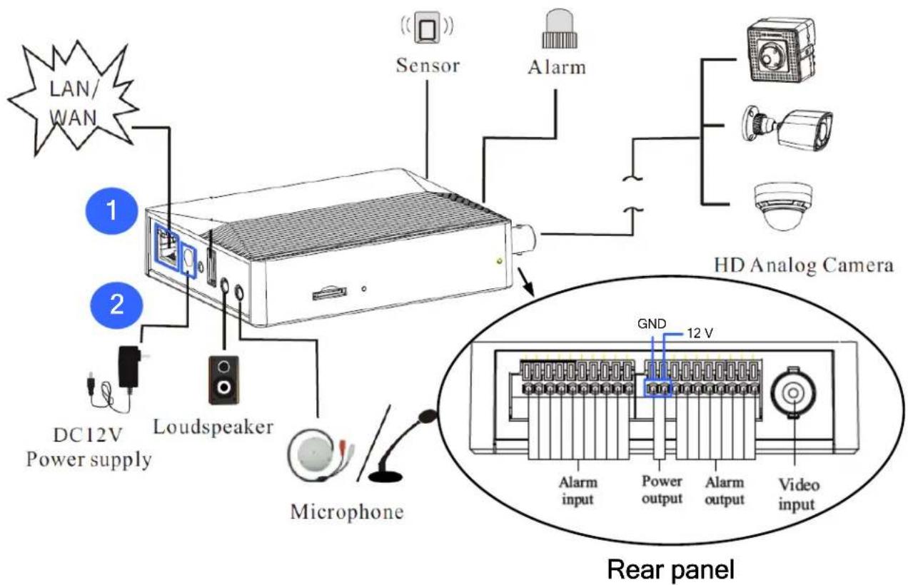
Power the video server by the following two alternatives:
- Connect an Ethernet cable to the PoE port.
- Connect a DC 12 V power adapter to the video server.
Note:
- The USB port is currently not functional.
- The camera can be optionally powered by the main body by connecting two power wires (+, -) from the camera to the power output ports (12 V, GND) on the main body.
- The video server's power output is DC 12 V, 0.5 A (Max. 5.5 W).
Chapter 3. Network Connection
System Requirement
For proper operating the product, the following requirements should be met for your computer.
Operating System: Windows 7 Home basic or higher
CPU: 2.0GHz or higher
RAM: 1G or higher
Display: 1920*1080 resolution or higher (recommended)
Web browser: IE (plug-in required)/ Firefox/Edge/Safari/Google Chrome
It is recommended to use the latest version of these web browsers.
The menu display and operation of the device may be slightly different by using the browser with plug-in or without plug-in. Installing plug-in will display more functions of the device.
Connect the device via LAN or WAN. Here only take IE browser for example. The details are as follows:
3.1 LAN
In LAN, there are two ways to access the device: 1. access through GV-IP Device Utility (V8.9.8 or later); 2. directly access through IE browser.
3.1.1 Assigning an IP Address Using GV-IP Device Utility
Network Connection

By default, when the camera is connected to LAN with DHCP server, it is automatically assigned with a dynamic IP address. Follow the steps below to look up its IP address, and use the accessed IP address to log in from its Wen interface.
- Make sure the PC and the camera are connected to the LAN, and GV-IP Device Utility (V8.9.8 or later) is installed on the PC from our website.
- On GV-IP Device Utility window, click the button to search for the IP devices in the same LAN. Click the Name or Mac Address column to sort.
- Find the camera with its Mac Address, click on its IP address.

- For first-time users, you are requested to create a password.

- Type a new password and click OK.
- Click on its IP address again and select Webpage to open its Web interface.
- Type the set password on the login page and click Login.
IMPORTANT:
- By default, the Administrator's username is admin and cannot be modified.
- To change the password using GV-IP Device Utility, click on the camera's IP address, and select Configure > Change Password. Or you can optionally change the password on the camera's Web interface by clicking Config→Security→User; see "Modify User" in 5.6.1 User Configuration.
A login box will appear as the following.

Please enter the user name (admin) and password. Then select the stream type and language as needed.
Stream Type: The plug-in free live view only supports1080P or lower resolution.
The security questions should be set after you click "Login" button. It is very important for you to reset your password. Please remember these answers.
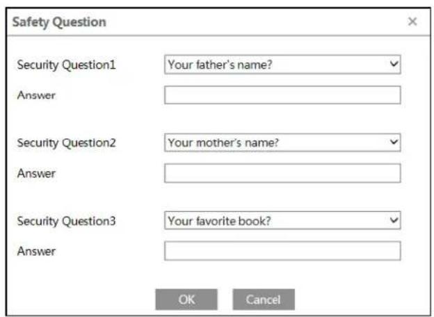
If you forget the admin password, you can reset the password by clicking Forget Password on the login page. Then you can reset the password by the security questions and answers you set.
You can set the account security question during the activation, or you can go to Config→Security→User, click Safety Question, select the security questions and input your answers.
3.1.2 Directly Access through IE
The default network settings are as shown below:
IP address: 192.168.0.10
Subnet Mask: 255.255.255.0
Gateway: 192.168.226.1
HTTP: 80
Data port: 9008
Use the above default settings when logging in the device for the first time. Directly connect the device to the computer through network cable.

Device

Network Cable

Computer
- Manually set the IP address of the PC and the network segment should be as the same as the default settings of the device. Open the network and share center. Click "Local Area Connection" to pop up the following window.

Select "Properties" and then select internet protocol according to the actual situation (for example: IPv4). Next, click the "Properties" button to set the network of the PC.

- Open the IE browser and enter the default address of the device and confirm.
- Follow directions to download and install the plug-in.
- Enter the default username and password in the login window and then enter to view.
3.2 WAN
Access through the router or virtual server.
![graph LR A["Device"] -->|Network Cable| B["Router"] B -->|Network Cable| C["Internet"] C -->|Network| D["Computer"]](/content/2026/05/1106473/images/73b095909aefd74e374af0541ecdfaa2d9457fc1427407b4af3a21b94cd50479.jpg)
- Make sure the device is connected to the local network and then log in via LAN and go to Config→Network→Port menu to set the port number.
| HTTP Port | 80 |
| HTTPS Port | 443 |
| Data Port | 9008 |
| RTSP Port | 554 |
- Go to Config → Network → TCP/IP menu to modify the IP address.
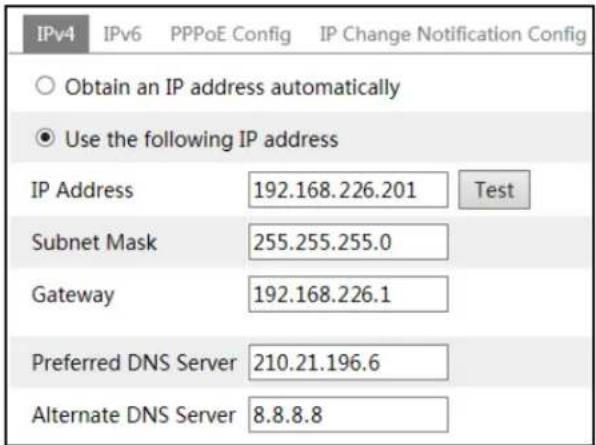
- Go to the router's management interface through IE browser to forward the IP address and port of the device in the "Virtual Server".
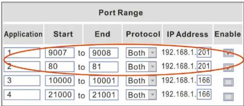
- Open the IE browser and enter its WAN IP and http port to access. (for example, if the http port is changed to 81, please enter "192.198.1.201:81" in the address bar of web browser to access).
Access through PPPoE dial-up
Network connection
![graph LR A["Device"] --> B["Modem"] B --> C["Internet"] C --> D["Computer"]](/content/2026/05/1106473/images/f3f4487121c39d6c9958abaee896fc28520eae61b7667fdd1bca823c63abb197.jpg)
Access the device through PPPoE auto dial-up. The setup steps are as follow:
-
Go to Config→Network→Port menu to set the port number.
-
Go to Config → Network → TCP/IP → PPPoE Config menu. Enable PPPoE and then enter the user name and password from your internet service provider.

- Go to Config → Network → DDNS menu. Before configuring the DDNS, please apply for a domain name first. Please refer to DDNS configuration for detail information.
- Open the IE browser and enter the domain name and http port to access.
Access through static IP
Network connection
![graph LR A["Device"] --> B["Network Cable"] B --> C["Internet"] C --> D["Network Cable"] D --> E["Computer"]](/content/2026/05/1106473/images/c42db38d8cf3de8975ac752f8c2a00cb535891770cc3d88df7a30db4b3438b99.jpg)
The setup steps are as follow:
- Go to Config→Network→Port menu to set the port number.
- Go to Config → Network → TCP/IP menu to set the IP address. Check "Use the following IP address" and then enter the static IP address and other parameters.
- Open the IE browser and enter its WAN IP and http port to access.
Chapter 4. Live View
After logging in the network camera web GUI successfully, user is allowed to view live video as follows.
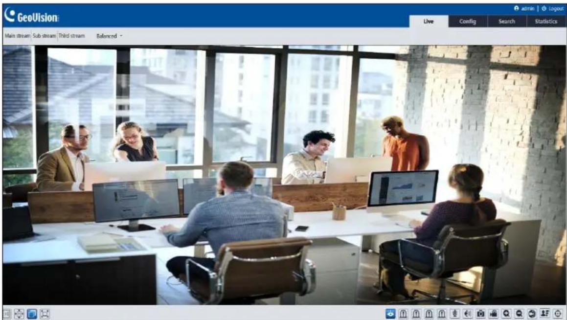
The following table is the instructions of the icons on the live view interface.
| Icon | Description | Icon | Description | |
 | Original size | SD card recording indicator | ||
 | Fit correct scale | Sensor alarm indicator | ||
 | Auto (fill the window) | Motion alarm indicator | ||
 | Full screen | Color abnormal indicator | ||
 | Start/stop live view | Abnormal clarity indicator | ||
 | Start/stop two-way audio | Scene change indicator | ||
 | Enable/disable audio | Line Crossing indicator | ||
| [DDAC] | Snapshot | Region Intrusion indicator | ||
| [6EZ3] | Start/stop local recording | Region Entrance indicator | ||
 | Zoom in | Region Exiting indicator | ||
| [C044] | Zoom out | Face detection indicator | ||
| [Y3ZS] | Enable/disable alarm output | Target counting (by line) indicator | ||
 | ||||
 | Face capture | Target counting (by area) indicator | ||
 | Rule information display | Object detection indicator (object abandoned/missing) | ||
| Icon | Description | Icon | Description |
| Alarm output indicator | Heat map indicator | ||
| COC (UTC) control |
Note:
- Those smart alarm indicators will flash only when the device supports those functions and the corresponding events are enabled.
- Plug-in free live view: Two-way audio and local recording are not supported and the preview mode switch (real-time/balanced/fluent mode) is not available too. In full screen mode, double click on the mouse to exit or press the ESC key on the keyboard.
COC (/UTC) control:
COC (/UTC) control allows the user to remotely set the OSD menu for analog cameras over coaxial cable.
Click to enter UTC control mode. The following buttons will display on the right panel of the live interface.

Click in the middle to call the OSD menu of the analog covert camera.

Move up or down to select the left menu by clicking or . After selecting the desired menu, click to enter the sub-menu or confirm the selection.
Select the right menu by clicking or .
means that there are sub-menus. After it is selected, click ■ to view the detailed menus.
Video output switch:
- Click to enter the main menu.
- Click ▼ to select "ADJUST" and then click ■ to confirm.
- Click to select "MONITOR OUT".
- Click ◀ or ▶ to select AHD/THD (TVI)/CHD (CVI)/CVBS. After you select one of them, click ■ to confirm. Then click ▶ to select "APPLY" or "RET". If "RET" is selected, you need to select the video output again. If "APPLY" is selected, the switch will succeed after the system reboots automatically.
Language Selection:
- Click to enter the main menu.
- Click ▼ to select "SPECIAL" and then click ■ to confirm.
- Click ▼ to select "LANGUAGE". Select the desired language by clicking ◀ or ▶.
Note: It is recommended to use the default settings for other parameters.
Chapter 5. Network Camera Configuration
In the Webcam client, choose "Config" to go to the configuration interface.
Note: Wherever applicable, click the "Save" button to save the settings.
5.1 System Configuration
5.1.1 Basic Information
In the "Basic Information" interface, the system information of the device is listed.

5.1.2 Date and Time
Go to Config→System→Date and Time. Please refer to the following interface.

Select the time zone and DST as required.
Note: The time zone of the device and the computer must be the same. It is recommended to modify the time zone of the device according to the time zone of the computer. If the time zone of the computer is modified, the current web client needs to be closed. Then re-open it and log in again.
Click the "Date and Time" tab to set the time mode and time format.

5.1.3 Local Config
Go to Config→System→Local Config to set up the storage path of captured pictures and recorded videos on the local PC. There is also an option to enable or disable the bitrate display in the recorded files.

Additionally, "Local smart snapshot storage" can be enabled or disabled here. If enabled, the captured pictures triggered by smart events (like line crossing detection, region intrusion, etc.) will be saved to the local PC.
Note: When you access your device by the web browser without the plug-in, only Show Bitrate can be set in the above interface.
5.1.4 Storage
Go to Config→System→Storage to go to the interface as shown below.

- SD Card Management
Click the "Format" button to format the SD card. All data will be cleared by clicking this button. Click the "Eject" button to stop writing data to SD card. Then the SD card can be ejected safely. Snapshot Quota: Set the capacity proportion of captured pictures on the SD card. Video Quota: Set the capacity proportion of record files on the SD card.
- Schedule Recording Settings
- Go to Config→System→Storage→Record to go to the interface as shown below.

- Set record stream, pre-record time, cycle writing.
Pre Record Time: Set the time to record before the actual recording begins.
- Set schedule recording. Check "Enable Schedule Record" and set the schedule.

Weekly schedule
Set the alarm time from Monday to Sunday for a single week. Each day is divided in one-hour increments. Green means scheduled. Blank means unscheduled.
Add: Add the schedule for a special day. Drag the mouse to set the time on the timeline.
Erase: Delete the schedule. Drag the mouse to erase the time on the timeline.
Manual Input: Click it for a specific day to enter specific start and end times. This adds more granularities (minutes).
Day schedule
Set the alarm time for alarm a special day, such as a holiday.
Note: Holiday schedule takes priority over weekly schedule.
- Snapshot Settings
Go to Config→System→Storage→Snapshot to go to the interface as shown below.
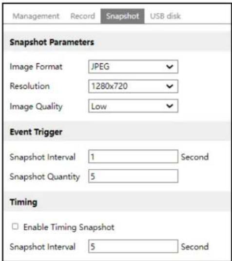
Set the format, resolution and quality of the image saved on the SD card and the snapshot interval and quantity and the timing snapshot here.
Snapshot Quantity: The number you set here is the maximum quantity of snapshots. The actual quantity of snapshots may be less than this number. Supposing the occurrence time of an alarm event is less than the time of capturing pictures, the actual quantity of snapshots is less than the set quantity of snapshots.
Timing Snapshot: Enable timing snapshot first and then set the snapshot interval and schedule. The setup steps of schedule are the same as the schedule recording (See Schedule Recording Settings).
- USB Disk
You can view the capacity of the USB storage device, such as total capacity, used capacity and available capacity.
5.2 Image Configuration
5.2.1 Display Settings
Go to Image→Display interface as shown below. The image's brightness, contrast, hue and saturation and so on for common, day and night mode can be set up separately. The image effect can be quickly seen by switching the configuration file.
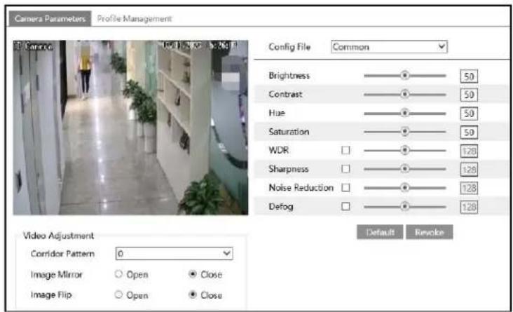
Brightness: Set the brightness level of the camera's image.
Contrast: Set the color difference between the brightest and darkest parts.
Hue: Set the total color degree of the image.
Saturation: Set the degree of color purity. The purer the color, the brighter the image is.
WDR: WDR can adjust the camera to provide a better image when there are both very bright and very dark areas simultaneously in the field of the view by lowering the brightness of the bright area and increasing the brightness of the dark area.
Recording will be stopped for a few seconds while the mode is changing from non-WDR to WDR mode.
Sharpness: Set the resolution level of the image plane and the sharpness level of the image edge.
Noise Reduction: Decrease the noise and make the image more thorough. Increasing the value will make the noise reduction effect better but it will reduce the image resolution.
Defog: Activating this function and setting an appropriate value as needed in foggy, dusty, smoggy or rainy environment to get clear images.
Corridor Pattern: Corridor viewing modes can be used for situations such as long hallways. 0, 90, 180 and 270 are available. The default value is 0.
Image Mirror: Turn the current video image horizontally.
Image Flip: Turn the current video image vertically.
After that, clicking "Default" button will not take effect.
Schedule Settings of Image Parameters:
Click the "Profile Management" tab as shown below.

Set full time schedule for common mode and specified time schedule for day and night. Choose "Timing" in the drop-down box of schedule as shown below.

Drag “☐” icons to set the time of day and night. Blue means day time and blank means night time. If the current mode of camera parameters is set to schedule, the image configuration mode will automatically switch between day and night according to the schedule.
5.2.2 Video / Audio Configuration
Go to Image→Video / Audio interface as shown below. In this interface, set the resolution, frame rate, bitrate type, video quality and so on subject to the actual network condition.

Three video streams can be adjustable.
Resolution: The size of image.
Frame rate: The higher the frame rate, the video is smoother.
Bitrate type: CBR and VBR are optional. Bitrate is related to image quality. CBR means that no matter how much change is seen in the video scene, the compression bitrate will be kept constant. VBR means that the compression bitrate will be adjusted according to scene changes. For example, for scenes that do not have much movement, the bitrate will be kept at a lower value. This can help optimize the network bandwidth usage.
Bitrate: it can be adjusted when the mode is set to CBR. The higher the bitrate, the better the image quality will be.
Video Quality: It can be adjusted when the mode is set to VBR. The higher the image quality, the more bitrate will be required.
I Frame interval: It determines how many frames are allowed between a “group of pictures”. When a new scene begins in a video, until that scene ends, the entire group of frames (or pictures) can be considered as a group of pictures. If there is not much movement in the scene, setting the value higher than the frame rate is fine, potentially resulting in less bandwidth usage. However, if the value is set too high, and there is a high frequency of movement in the video, there is a risk of frame skipping.
Video Compression: MJPEG, H264+, H264, H265 or H265+ can be optional. MJPEG is not available for main stream. If H.265/H.265+ is chosen, make sure the client system is able to decode H.265/H.265+. Compared to H.265, H.265+ saves more storage space with the same maximum bitrate in most scenes. Compared to H.264, H.265 reduces the transmission bitrate under the same resolution, frame rate and image quality.
Profile: For H.264. Baseline, main and high profiles are selectable.
Send Snapshot: Set the snapshot stream.
Video encode slice split: If this function is enabled, smooth image can be gotten even though using the low-performance PC.
Watermark: When playing back the local recorded video in the search interface, the watermark can be displayed. To enable it, check the watermark box and enter the watermark text.
Click the "Audio" tab to go to the interface as shown below.
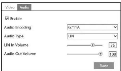
Audio Encoding: G711A and G711U are selectable.
Audio Type: Only LINE is available.
LIN In Volume: LINE IN Volume can be set here.
Audio Out Volume: Audio Out Volume can be set here.
5.2.3 OSD Configuration
Go to Image→OSD interface as shown below.

Set time stamp, device name, OSD content and picture overlap here. After enabling the corresponding display and entering the content, drag them to change their position. Then click the "Save" button to save the settings.

Picture Overlap Settings:
Check "OSD Content1", choose "Picture Overlay" and click "Browse" to select the overlap picture. Then click "Upload" to upload the overlap picture. The pixel of the image shall not exceed 200*200, or it cannot be uploaded.
5.2.4 Video Mask
Go to Image→Video Mask interface as shown below. A maximum of 4 zones can be set up.
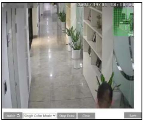
To set up video mask:
- Enable video mask.
- Click the "Draw Area" button and then drag the mouse to draw the video mask area.
- Click the "Save" button to save the settings.
- Return to the live to verify that the area has been drawn as shown as blocked out in the image.
To clear the video mask:
Click the "Clear" button to delete the current video mask area.
5.2.5 ROI Configuration
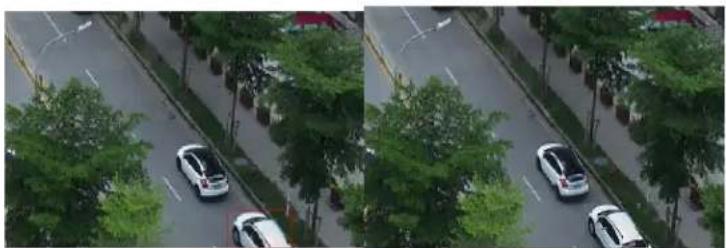
Go to Image→ROI Config interface as shown below. An area in the image can be set as a region of interest. This area will have a higher bitrate than the rest of the image, resulting in better image quality for the identified area.
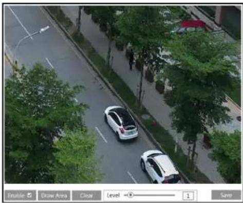
- Check "Enable" and then click the "Draw Area" button.
- Drag the mouse to set the ROI area.
- Set the level.
- Click the "Save" button to save the settings.
5.3 Alarm Configuration
5.3.1 Motion Detection
Go to Alarm→Motion Detection to set motion detection alarm.
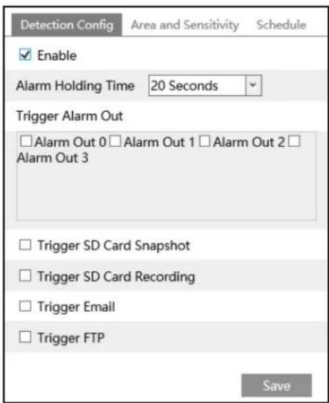
- Check "Enable" check box to activate motion-based alarms. If unchecked, the camera will not send out any signals to trigger motion-based recording to the NVR or CMS, even if there is motion in the video.
Alarm Holding Time: it refers to the interval time between the adjacent motion detections. For instance, if the alarm holding time is set to 20 seconds, once the camera detects a motion, it will go to alarm and would not detect any other motion in 20 seconds. If there is another motion detected during this period, it will be considered as continuous movement; otherwise, it will be considered as a single motion.
Alarm Out: If selected, this would trigger external relay outputs that are connected to the camera on detecting a motion-based alarm.
Trigger SD Card Snapshot: If selected, the system will capture images on motion detection and save the images on an SD card.
Trigger SD Card Recording: If selected, video will be recorded on an SD card on motion detection.
Trigger Email: If "Trigger Email" and "Attach Picture" are checked (email address must be set first in the Email configuration interface), the captured pictures and triggered event will be sent into those addresses.
Trigger FTP: If "Trigger FTP" and "Attach Picture" are checked, the captured pictures will be sent into FTP server address. Please refer to 5.5.10 FTP configuration chapter for more details.
- Set motion detection area and sensitivity. Click the "Area and Sensitivity" tab to go to the interface as shown below.

Move the "Sensitivity" scroll bar to set the sensitivity. Higher sensitivity value means that motion will be triggered more easily.
Select "Add" and click "Draw". Drag the mouse to draw the motion detection area; Select "Erase" and drag the mouse to clear motion detection area.
After that, click the "Save" to save the settings.
- Set the schedule for motion detection. The schedule setup steps of the motion detection are the same as the schedule recording setup (See Schedule Recording Settings).
5.3.2 Exception Alarm
- SD Card Full
- Go to Config→Alarm→Exception Alarm→SD Card Full.

-
Click "Enable".
-
Set the alarm holding time and alarm trigger options. The setup steps are the same as motion detection. Please refer to 5.3.1 Motion Detection for details.
- SD Card Error
When there are some errors in writing SD card, the corresponding alarms will be triggered.
- Go to Config→Alarm→Exception Alarm→SD Card Error as shown below.
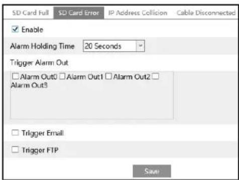
- Click "Enable".
- Set the alarm holding time and alarm trigger options. Trigger alarm out, Email and FTP. The setup steps are the same as motion detection. Please refer to 5.3.1 Motion Detection for details.
- IP Address Collision
- Go to Config→Alarm→Exception Alarm→IP Address Collision as shown below.

- Click "Enable" and set the alarm holding time.
- Trigger alarm out. When the IP address of the device is in conflict with the IP address of other devices, the system will trigger the alarm out.
- Cable Disconnection
- Go to Config→Alarm→Exception Alarm→Cable Disconnected as shown below.

- Click "Enable" and set the alarm holding time.
- Trigger alarm out. When the device is disconnected, the system will trigger the alarm out.
5.3.3 Alarm In
This function is only available for some models. To set sensor alarm (alarm in): Go to Config→Alarm→Alarm In interface as shown below.

- Click "Enable" and set the alarm type, alarm holding time and sensor name.
- Set alarm trigger options. The setup steps are the same as motion detection. Please refer to 5.3.1 Motion Detection for details.
- Click "Save" button to save the settings.
- Set the schedule of the sensor alarm. The setup steps of the schedule are the same as the schedule recording setup. (See Schedule Recording Settings).
Select the sensor ID and click "Apply settings to" to quickly apply the settings to the other alarm input.
5.3.4 Alarm Out
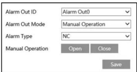
This function is only available for some models. Go to Config→Alarm→Alarm Out.
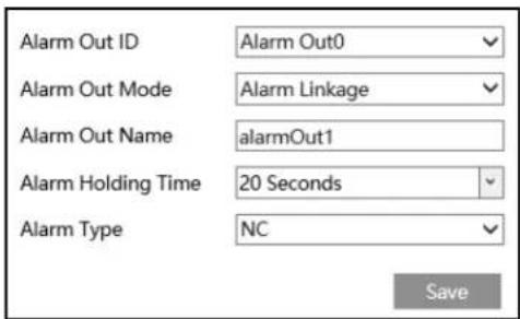
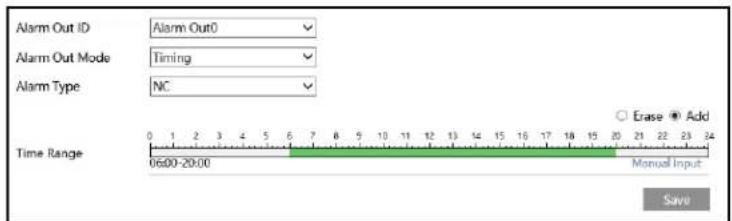
Alarm Out ID: The alarm out can be set respectively by selecting alarm out ID.
Alarm Out Mode: Alarm linkage, manual operation and timing are optional.
Alarm Linkage: Having selected this mode, select alarm out name, alarm holding time at the "Alarm Holding Time" pull down list box and alarm type.
Manual Operation: Having selected this mode, select the alarm type and click "Open" to trigger the alarm out immediately; click "Close" to stop alarm.
Timing: Select the alarm type. Then click "Add" and drag the mouse on the timeline to set the schedule of alarm out; click "Erase" and drag the mouse on the timeline to erase the set time schedule. After this schedule is saved, the alarm out will be triggered in the specified time.
5.3.5 Alarm Server
Go to Alarm→Alarm Server interface as shown below.
Set the server address, port, heartbeat and heartbeat interval. When an alarm occurs, the device will transfer the alarm event to the alarm server. If an alarm server is not needed, there is no need to configure this section.

5.4 Event Configuration
For more accuracy, here are some recommendations for installation.
- Cameras should be installed on stable surfaces, as vibrations can affect the accuracy of detection.
- Avoid pointing the camera at the reflective surfaces (like shiny floors, mirrors, glass, lake surfaces and so on).
- Avoid places that are narrow or have too much shadowing.
- Avoid scenario where the object's color is similar to the background color.
- At any time of day or night, please make sure the image of the camera is clear and with adequate and even light, avoiding overexposure or too much darkness on both sides.
5.4.1 Object Abandoned/Missing
Alarms will be triggered when the objects are removed from or left at the pre-defined area. To set abandoned/missing object detection:
Go to Config→Event→Object Abandoned/Missing interface as shown below.
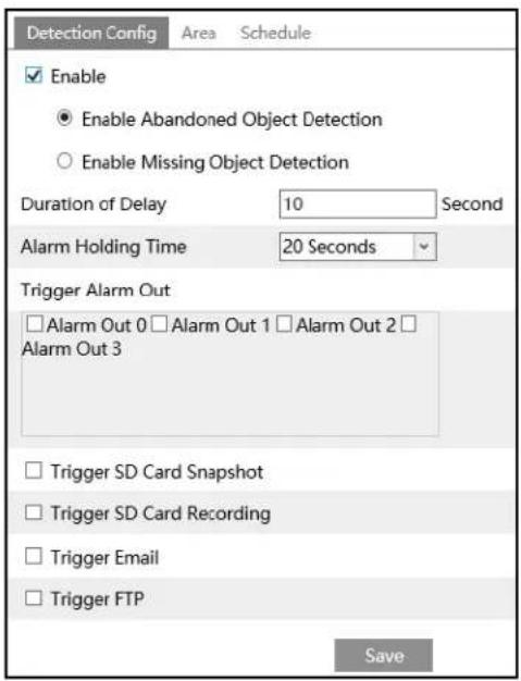
- Enable abandoned/missing object detection and then select the detection type.
Enable Abandoned Object Detection: Alarms will be triggered if there are items left in the pre-defined area.
Enable Missing Object Detection: Alarms will be triggered if there are items missing in the pre-defined area.
Duration of Delay: It is the alarm delay time of the object left in the region (ranging from 10\~3600s) or the alarm delay time of the object removed from the region (ranging from 3\~3600s). For example, if “Enable Abandoned Object Detection” is selected and the duration of delay is set as 10, alarms will be triggered after the object is left and stay in the region for 10s, but when someone takes away the object within 10s, alarms will not be triggered.
-
Set the alarm holding time and alarm trigger options. The setup steps are the same as motion detection. Please refer to 5.3.1 Motion Detection for details.
-
Click "Save" button to save the settings.
-
Set the alarm area of the abandoned/missing object detection. Click the "Area" tab to go to the interface as shown below.

Set the alarm area number and then enter the desired alarm area name. Only one alarm area can be added. Click the "Draw Area" button and then click around the area where you want to set as the alarm area in the image (the alarm area should be a closed area). Click the "Stop Draw" button to stop drawing. Click the "Clear" button to delete the alarm area. Click the "Save" button to save the settings.
- Set the schedule of the abandoned/missing object detection. The setup steps of schedule are the same as the schedule recording (See Schedule Recording Settings).
※ The configuration requirements of camera and surrounding areas
- The range of the detection object should occupy from 1/50 to 1/3 of the entire image.
- The detection time of objects in the camera shall be from 3 to 5 seconds.
- The defined area cannot be covered frequently and continuously (like people and traffic flow).
- It is necessary for missing object detection that the drawn frame must be very close to the margin of the object in enhancing the sensitivity and accuracy of the detection.
- Abandoned/missing object detection cannot determine the objects' ownership. For instance, there is an unattended package in the station. Abandoned object detection can detect the package itself but it cannot determine to whom it belongs to.
- Try not to enable abandoned/missing object detection when light changes greatly in the scene.
- Try not to enable abandoned/missing object if there are complex and dynamic environments in the scene.
- Adequate light and clear scenery are very important to abandoned/missing object detection.
5.4.2 Video Exception
This function can detect changes in the surveillance environment affected by the external factors.
To set exception detection:
Go to Config→Event→Video Exception interface as shown below.

- Enable the applicable detection that's desired.
Scene Change Detection: Alarms will be triggered if the scene of the monitor video has changed.
Video Blur Detection: Alarms will be triggered if the video becomes blurry.
Abnormal Color Detection: Alarms will be triggered if the image is abnormal caused by color deviation.
- Set the alarm holding time and alarm trigger options. The setup steps are the same as motion detection. Please refer to 5.3.1 Motion Detection for details.
- Click "Save" button to save the settings.
- Set the sensitivity of the exception detection. Click "Sensitivity" tab to go to the interface as shown below.
![graph LR A["Detection Configuration"] --> B["Sensitivity"] B --> C["28"] C --> D["Save"]](/content/2026/05/1106473/images/249431ee5a1a7e3c6d13d704ca3c0848f13f0032e76d2b6578bf90a51b56a5af.jpg)
Drag the slider to set the sensitivity value or directly enter the sensitivity value in the textbox. Click "Save" button to save the settings.
The sensitivity value of Scene Change Detection: The higher the value is, the more sensitive the system responds to the amplitude of the scene change.
The sensitivity value of Video Blur Detection: The higher the value is, the more sensitive the system responds to the blurriness of the image.
The sensitivity value of Abnormal Color Detection: The higher the value is, the more sensitive the system responds to the color shift of the image.
※ The requirements of camera and surrounding area
- Auto-focusing function should not be enabled for exception detection.
- Try not to enable exception detection when light changes greatly in the scene.
- Please contact us for more detailed application scenarios.
5.4.3 Line Crossing
Line Crossing: Alarms will be triggered if the target crosses the pre-defined alarm lines. Go to Config→Event→Line Crossing interface as shown below.
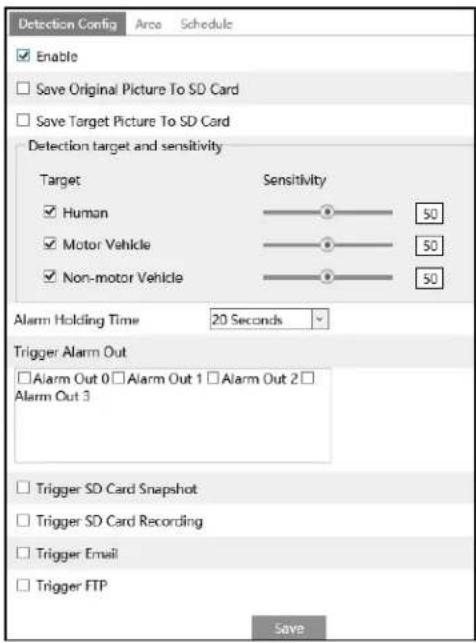
- Enable line crossing alarm and select the snapshot type and the detection target.
Save Original Picture to SD Card: If it is enabled, the detected original pictures will be captured and saved to the SD card when the targets cross the alarm line.
Save Target Picture to SD Card: If it is enabled, the detected target cutout pictures will be captured and saved to the SD card when the targets cross the alarm line.
Note: To save snapshots to the local PC, please enable "Local Smart Snapshot Storage" in the local config interface first. To save snapshots to the SD card, please install an SD card first.
Detection Target:
Human: Select it and then alarms will be triggered if someone crosses the pre-defined alarm lines.
Motor Vehicle: Select it and then alarms will be triggered if a vehicle with four or more wheels (eg. a car, bus or truck) crosses the pre-defined alarm lines.
Motorcycle/Bicycle: Select it and then alarms will be triggered if a vehicle with two wheels (eg. a motorcycle or bicycle) crosses the pre-defined alarm lines.
All of the three types of objects can be selected simultaneously. Please select the detection objects as needed. If no object/target is selected, alarms will not be triggered even if line crossing detection is enabled.
- Set the alarm holding time.
- Set alarm trigger options. The setup steps are the same as motion detection. Please refer to 5.3.1 Motion Detection for details.
- Click "Save" button to save the settings.
- Set area of the line crossing alarm. Click the "Area" tab to go to the interface as shown below.
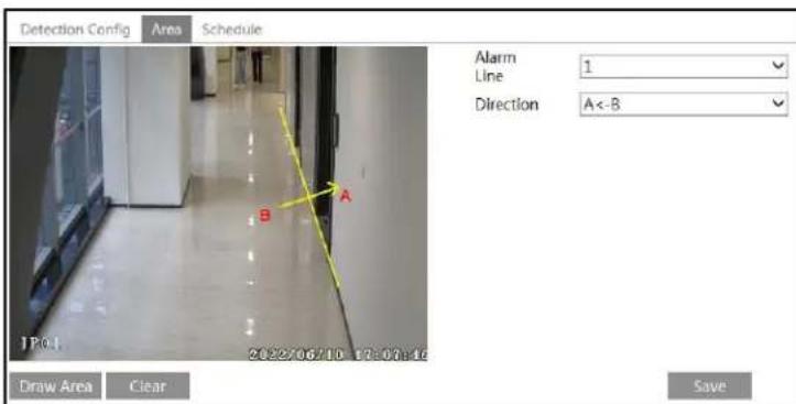
Set the alarm line number and direction. Up to 4 lines can be added. Multiple lines cannot be added simultaneously.
Direction: A<->B, A->B and A<-B optional. This indicates the direction of the intruder/vehicle crosses over the alarm line.
A<->B: The alarm will be triggered when the intruder/vehicle crosses over the alarm line from B to A or from A to B.
A->B: The alarm will be triggered when the intruder/vehicle crosses over the alarm line from A to B.
A<-B: The alarm will be triggered when the intruder/vehicle crosses over the alarm line from B to A.
Click the "Draw Area" button and then drag the mouse to draw a line in the image. Click the "Stop Draw" button to stop drawing. Click the "Clear" button to delete the lines. Click the "Save" button to save the settings.
- Set the schedule of the line crossing alarm. The setup steps of the schedule are the same as the schedule recording setup (See Schedule Recording Settings).
※ Configuration of camera and surrounding area
- Auto-focusing function should not be enabled for line crossing detection.
- Avoid the scenes with many trees or the scenes with various light changes (like many flashing headlights). The ambient brightness of the scenes shouldn't be too low.
- Cameras should be mounted at a height of 2.8 meters or above.
- Keep the mounting angle of the camera at about 45° .
- The detected objects should not be less than 1% of the entire image and the largest sizes of the detected objects should not be more than 1/8 of the entire image.
- Make sure cameras can view objects for at least 2 seconds in the detected area for accurate detection.
- Adequate light and clear scenery are crucial for line crossing detection.
5.4.4 Region Intrusion
Region Intrusion: Alarms will be triggered if the target intrudes into the pre-defined areas. This function can be applicable to important supervision places, danger areas and prohibited areas, like military administrative zones, high danger areas, no man's areas, etc.
Go to Config→Event→Region Intrusion interface as shown below.

- Enable intrusion detection and select the snapshot type and the detection target.
Save Original Picture to SD Card: If it is enabled, the detected original pictures will be captured and saved to the SD card when the targets intrude into the pre-defined areas.
Save Target Picture to SD Card: If it is enabled, the detected target cutout pictures will be captured and saved to the SD card when the targets intrude into the pre-defined areas.
Note: To save snapshots to the local PC, please enable "Local Smart Snapshot Storage" in the local config interface first. To save snapshots to the SD card, please install an SD card first.
Detection Target:
Human: Select it and then alarms will be triggered if someone intrudes into the pre-defined area.
Motor Vehicle: Select it and then alarms will be triggered if a vehicle with four or more wheels (eg. a car, bus or truck) intrudes into the pre-defined area.
Non-motor Vehicle: Select it and then alarms will be triggered if a vehicle with two wheels (eg. a motorcycle or bicycle) intrudes into the pre-defined area.
All of the three types of objects can be selected simultaneously. Please select the detection objects as needed. If no object/target is selected, alarms will not be triggered even if intrusion detection is enabled.
- Set the alarm holding time.
- Set alarm trigger options. The setup steps are the same as motion detection. Please refer to 5.3.1 Motion Detection for details.
- Click the "Save" button to save the settings.
- Set the alarm area of the region intrusion detection. Click the "Area" tab to go to the interface as shown below.

Set the alarm area number on the right side. Up to 4 alarm areas can be added.
Click the "Draw Area" button and then click around the area where you want to set as the alarm area in the image on the left side (the alarm area should be a closed area). Click the "Stop Draw" button to stop drawing. Click the "Clear" button to delete the alarm area. Click the "Save" button to save the settings.
- Set the schedule of the region intrusion detection. The setup steps of the schedule are the same as schedule recording setup (See Schedule Recording Settings).
※ Configuration requirements of camera and surrounding area
- Auto-focusing function should not be enabled for region intrusion detection.
- Avoid the scenes with many trees or the scenes with various light changes (like many flashing headlights). The ambient brightness of the scenes shouldn't be too low.
- Cameras should be mounted at a height of 2.8 meters or above.
- Keep the mounting angle of the camera at about 45° .
- The detected objects should not be less than 1% of the entire image and the largest sizes of the detected objects should not be more than 1/8 of the entire image.
- Make sure cameras can view objects for at least 2 seconds in the detected area for accurate detection.
- Adequate light and clear scenery are crucial to region intrusion detection.
5.4.5 Region Entrance
Region Entrance: Alarms will be triggered if the target enters the pre-defined areas.
Go to Config→Event→Region Entrance interface.
- Enable region entrance detection and select the snapshot type and the detection target.
- Set the alarm holding time and alarm trigger options.
- Set the alarm area of the region entrance detection.
- Set the schedule of the region entrance detection.
The setup steps of the region entrance detection are the same as the region intrusion detection setup (See 5.4.4 Region Intrusion for details).
5.4.6 Region Exiting
Region Exiting: Alarms will be triggered if the target exits from the pre-defined areas.
Go to Config→Event→Region Exiting interface.
- Enable region exiting detection and select the snapshot type and the detection target.
- Set the alarm holding time and alarm trigger options.
- Set the alarm area of the region exiting detection.
- Set the schedule of the region exiting detection.
The setup steps of the region exiting detection are the same as the region intrusion detection setup (See 5.4.4 Region Intrusion for details).
5.4.7 Target Counting by Line
This function is to calculate the number of the people or vehicles crossing the alarm line through detecting, tracking and counting the shapes of the people or vehicles.
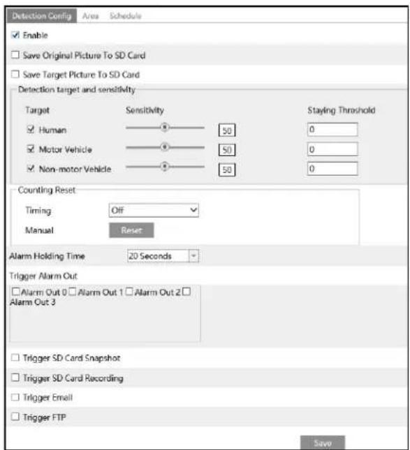
- Go to Config→Event→Target Counting by Line as shown below.

- Enable target counting by line and select the snapshot type and the detection target.
Detection Target: Select the target to calculate. Human, motor vehicle and motorcycle/bicycle can be selected.
Staying Threshold: When the targets (human/vehicle) staying in the specified area exceed the threshold, alarms will be triggered.
Counting Reset: The current number of the target counting can be reset. You can choose to reset the counting daily, weekly or monthly. Click "Reset" to manually reset the current number of crossing line people/car/bike counting.
-
Set the alarm trigger options. The setup steps are the same as motion detection. Please refer to 5.3.1 Motion Detection for details.
-
Set the alarm line. Click the "Area" tab to go to the interface as shown below.
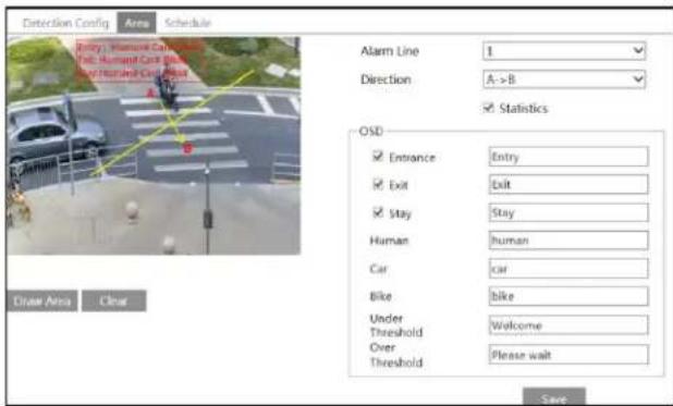
Set the alarm line number and direction. Only one alarm line can be added.
Direction: A->B and A<-B can be optional. The direction of the arrow is entrance.
Statistics: If enabled, you can see the statistical information in the live view interface. If disabled, the statistical information will not be displayed in the live view interface.
The statistical OSD information can be customized as needed.
Click the "Draw Area" button and then drag the mouse to draw a line in the image. Check "Statistics" and then move the red box to change the position of the statistical information displayed on the screen. Click the "Stop Draw" button to stop drawing. Click the "Clear" button to delete the lines.
Click the "Save" button to save the settings.
-
Set the schedule of the target counting by line. The setup steps of the schedule are the same as schedule recording setup (See Schedule Recording Settings).
-
View the statistical information in the live view interface.

- View the statistical information of target counting by line. Click "Statistics" to enter the following interface.
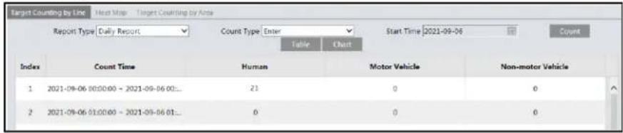
Select the report type. Daily report, weekly report, monthly report and annual report are selectable.
Select the count type. Enter or leave can be optional.
Select the start time and then click "Count". Then the counting result will display in the statistic result area. Click Table or Chart to display the result in different way.

5.4.8 Target Counting by Area
This function is to calculate the number of the people or vehicles intruding into the pre-defined area through detecting, tracking and counting the shapes of the people or vehicles.
- Go to Config→Event→Target Counting by Area as shown below.
-
Enable target counting by area, select the snapshot type, the detection target, counting reset and alarm linkages. The setup steps are the same as the target counting by line.
-
Set the statistic area. Click the "Area" tab to go to the interface as shown below.

Select the alarm area number on the right side. Only one alarm area can be added. Click the "Draw Area" button and then click around the area where you want to set as the alarm area in the image on the left side (the alarm area should be a closed area). Click the "Stop Draw" button to stop drawing. Click the "Clear" button to delete the alarm area. Click the "Save" button to save the settings.
- Set the schedule of the target counting by area. The setup steps of the schedule are the same as schedule recording setup (See Schedule Recording Settings).
- View the statistical information in the live view interface.

- View the statistical information of target counting by area. Click Statistics→Target Counting by Area to enter the following interface.
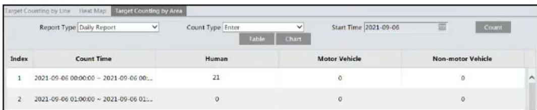
Please select report type, count type and start time as needed. Then click "Count" to search the statistic result. Click "Chart" to view the statistic result intuitively.
5.4.9 Face Detection
Face detection function is to detect the face appearing in the surveillance scene. Alarms will be triggered when a face is detected.
The setting steps are as follows:
- Go to Config→Event→Face Detection as shown below.

- Enable the face detection function.
Save Source Information to SD Card: if checked, the whole picture will be saved to the local PC or SD card when detecting a face.
Save Face Information to SD Card: if checked, the captured face picture will be saved to the local PC or SD card when detecting a face.
Note: To save images to the local PC, please enable the local smart snapshot storage first (Config→System→Local Config). To save images to the SD card, please install an SD card first.
- Set alarm holding time and alarm trigger options. The alarm trigger setup steps are the same as motion detection setup. Please refer to 5.3.1 Motion Detection for details.
Trigger alarm condition: all or mask off can be selectable.
All: Alarms will be triggered when the camera detects a face (with/without a mask).
Mask off: Alarms will be triggered when the detected person is not wearing a mask on the face.
- Set alarm detection area.
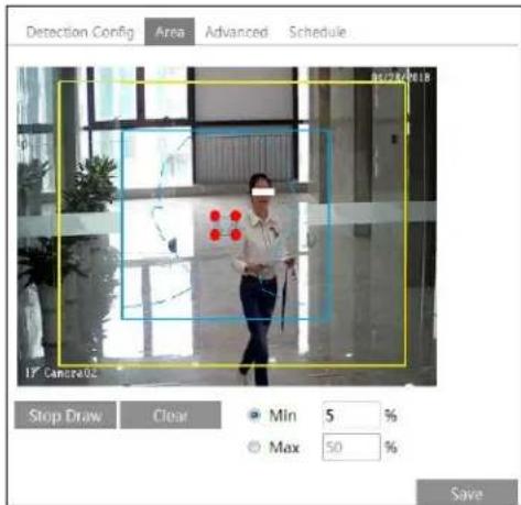
Click “Draw Area” and drag the border lines of the rectangle to modify its size. Move the rectangle to change its position. Click “Stop Draw” to stop drawing the area. Click “Clear” to clear the area. Then set the detectable face size by defining the maximum value and the minimum value (The default size range of a single face image occupies from 3% to 50% of the entire image).
- Advanced settings. Choose the snapshot interval and number as needed to avoid capturing multiple similar pictures in a very short period of time.
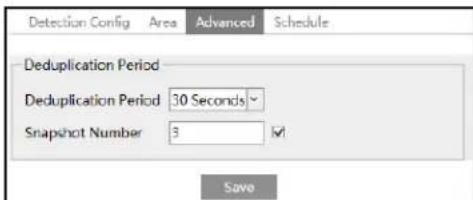
Deduplication Period: If 30 seconds is selected, the camera will capture the same target once every 30 seconds during its continuous tracking period.
Snapshot Number: If the snapshot number is enabled and set (eg. 3), the camera will capture the same target once every 30 seconds and it will capture this target 3 times at most during its continuous tracking period. If the snapshot number is disabled, the camera will capture the same target once every 30 seconds until the target disappears in the detected area.
- Set the schedule of the face detection. The setup steps of the schedule are the same as schedule recording setup (See Schedule Recording Settings).
Face Capture View
After enabling face detection function, return to the live view interface. Click 📄 to go to the following interface. When there are faces detected, the face pictures will be listed on the right. The features of captured faces also can be displayed, such as gender, whether to wear a mask, whether to wear glasses, age group, etc.

※ Configuration requirements of camera and surrounding area
- Cameras must be installed in the area with stable and adequate light sources.
- The installation height ranges from 2.0m to 3.5m, adjustable according to the focal-length of different lenses and object distances.
- The depression angle of the camera shall be less than or equal to 15° .
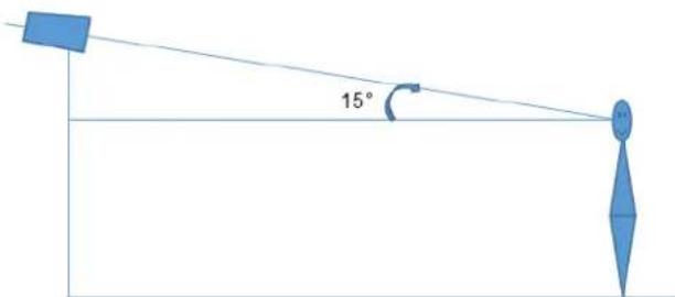
- The object distance depends on the focal-length of the lens mounted in the camera.
- To ensure the accuracy of face detection, the requirements for face capture are: left or right turn angle is less than about 30° ; pitching angle is less than 20° .
- The following scenes are not applicable, like crowded scenes (airport, railway station, square, etc), backlight scenes, crossroads and so on.
- Corridor mode is not applicable.
5.4.10 Heat Map
Heat Map is to display the flow distribution of people/vehicles in pre-defined areas by different colors.
- Enable Heat Map, set snapshot type and detection target type as needed.

- Set heat map display area. Up to 4 areas can be set.

Click the "Draw Area" button and then click around the area where you want to set as the alarm area in the image on the left side (the alarm area should be a closed area). Click the "Stop Draw" button to stop drawing. Click the "Clear" button to delete the alarm area. Click the "Save" button to save the settings.
- Set the schedule of heat map. The setup steps of the schedule are the same as schedule recording setup (See Schedule Recording Settings).
- View the heat map data (click Statistics→Heat Map). Set the start time and the end time.
Click "Count" to view the heat map as shown below. The default heat map is people flow data display. Click "Motor Vehicle" or "Non-motor Vehicle" to view the corresponding data.

5.5 Network Configuration
5.5.1 TCP/IP
Go to Config→Network→TCP/IP interface as shown below. There are two ways for network connection.

Use IP address (take IPv4 for example)-There are two options for IP setup: obtain an IP address automatically by DHCP and use the following IP address. Please choose one of the options as needed.
Test: Test the effectiveness of the IP address by clicking this button.
Use PPPoE-Click the "PPPoE Config" tab to go to the interface as shown below. Enable PPPoE and then enter the user name and password from your ISP.
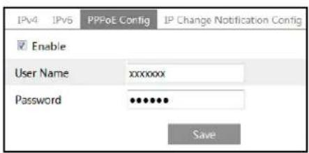
Either method of network connection can be used. If PPPoE is used to connect internet, the camera will get a dynamic WAN IP address. This IP address will change frequently. To be notified, the IP change notification function can be used.
Click "IP Change Notification Config" to go to the interface as shown below.

Trigger Email: when the IP address of the device is changed, the new IP address will be sent to the email address that has been set up.
Trigger FTP: when the IP address of the device is changed, the new IP address will be sent to FTP server that has been set up.
5.5.2 Port
Go to Config→Network→Port interface as shown below. HTTP port, Data port and RTSP port can be set.

HTTP Port: The default HTTP port is 80. It can be changed to any port which is not occupied.
HTTPS Port: The default HTTPS port is 443. It can be changed to any port which is not occupied.
Data Port: The default data port is 9008. Please change it as necessary.
RTSP Port: The default port is 554. Please change it as necessary.
Persistent Connection Port: The port is used for a persistent connection of the third-party platform to push smart data, like face pictures.
WebSocket Port: Communication protocol port for plug-in free preview.
5.5.3 DDNS
If the camera is set up with a DHCP connection, DDNS should be set for the internet.
- Go to Config→Network→DDNS.

- Apply for a domain name. Take www.dvrdyndns.com for example.
Enter www.dvrdydns.com in the IE address bar to visit its website. Then Click the "Registration" button.
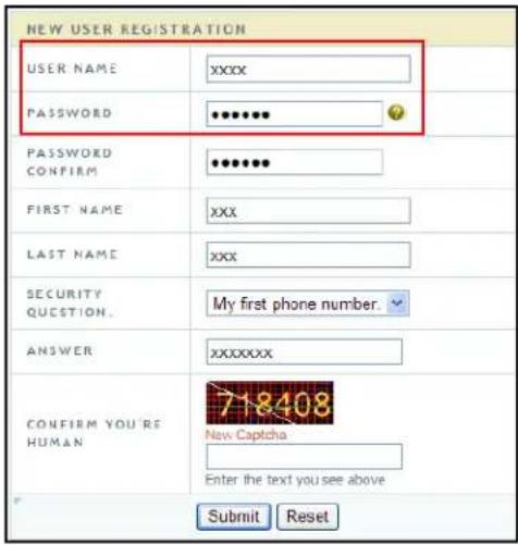
Create domain name.
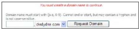
After the domain name is successfully applied for, the domain name will be listed as below.

- Enter the username, password, domain you apply for in the DDNS configuration interface.
- Click the "Save" button to save the settings.
5.5.4 SNMP
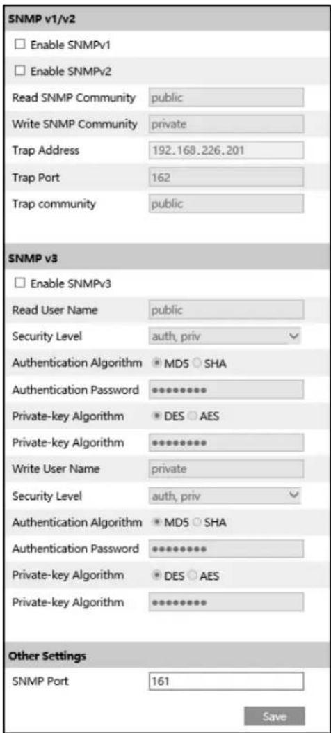
To get camera status, parameters and alarm information and remotely manage the camera, the SNMP function can be used. Before using SNMP, please install an SNMP management tool and set the parameters of the SNMP, such as SNMP port, trap address.
- Go to Config→Network→SNMP.
-
Check the corresponding version checkbox (Enable SNMPv1, Enable SNMPv2, Enable SNMPv3) according to the version of the SNMP software that will be used.
-
Set the values for "Read SNMP Community", "Write SNMP Community", "Trap Address", "Trap Port" and so on. Please make sure the settings are the same as that of the SNMP software.
Note: Please use the different version in accordance with the security level you required. The higher the version is, the higher the level of the security is.
5.5.5 802.1x
If it is enabled, the camera's data can be protected. When the camera is connected to the network protected by the IEE802.1x, user authentication is needed.

To use this function, the camera shall be connected to a switch supporting 802.1x protocol. The switch can be reckoned as an authentication system to identify the device in a local network. If the camera connected to the network interface of the switch has passed the authentication of the switch, it can be accessed via the local network.
Protocol type and EAPOL version: Please use the default settings.
User name and password: The user name and password must be the same with the user name and password applied for and registered in the authentication server.
5.5.6 RTSP
Go to Config→Network→RTSP.

Select "Enable" to enable the RTSP function.
Port: Access port of the streaming media. The default number is 554.
RTSP Address: The RTSP address (unicast) format that can be used to play the stream in a media player.
Multicast Address
Main stream: The address format is
"rtsp://IP address: rtsp port/profile1?transportmode=mcast".
Sub stream: The address format is
"rtsp://IP address: rtsp port/profile2?transportmode=mcast".
Third stream: The address format is
"rtsp://IP address: rtsp port/profile3?transportmode=mcast".
Audio: Having entered the main/sub stream in a VLC player, the video and audio will play automatically.
If "Allow anonymous login..." is checked, there is no need to enter the username and password to view the video.
If "auto start" is enabled, the multicast received data should be added into a VLC player to play the video.
Note:
-
This camera supports local video preview through a VLC player. Enter the RTSP address (unicast or multicast, eg. rtsp://192.168.226.201:554/profile1?transportmode=mcast) in a VLC player to realize the simultaneous video preview with the web client.
-
The IP address mentioned above cannot be the address of IPv6.
-
Avoid the use of the same multicast address in the same local network.
-
When playing the video through the multicast streams in a VLC player, please pay attention to the mode of the VLC player. If it is set to TCP mode, the video cannot be played.
-
If the coding format of the video of the main stream is MJPEG, the video may be disordered at some resolutions.
5.5.7 RTMP
You can access the third-party (like YouTube) to realize video live view through RTMP protocol.
Go to Config→Network→RTMP.

Check "Enable", select stream type, set the reconnection time after timeout and server address as needed.
Server address: Enter the server address allocated by the third-party server.
After that, click "Save" to save the settings. Then click "Refresh" to view the connection status.
5.5.8 UPNP
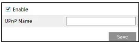
If this function is enabled, the camera can be quickly accessed through the LAN. Go to Config→Network→UPnP. Enable UPNP and then enter UPnP name.
5.5.9 Email
If you need to trigger Email when an alarm happens or IP address is changed, please set the Email here first.
Go to Config→Network →Email.

Sender Address: sender's e-mail address.
User name and password: sender's user name and password (you don't have to enter the username and password if "Anonymous Login" is enabled).
Server Address: The SMTP IP address or host name.
Select the secure connection type at the "Secure Connection" pull-down list according to what's required.
SMTP Port: The SMTP port.
Send Interval(S): The time interval of sending email. For example, if it is set to 60 seconds and multiple motion detection alarms are triggered within 60 seconds, they will be considered as only one alarm event and only one email will be sent. If one motion alarm event is triggered and then another motion detection alarm event is triggered after 60 seconds, two emails will be sent. When different alarms are triggered at the same time, multiple emails will be sent separately.
Click the "Test" button to test the connection of the account.
Recipient Address: receiver's e-mail address.
5.5.10 FTP
After an FTP server is set up, captured pictures from events will be uploaded to the FTP server.
- Go to Config→Network →FTP.

- Click "Add" to add the information of the FTP. After that, click "Save" to save the settings.
Server Name: The name of the FTP server.
Server Address: The IP address or domain name of the FTP.
Upload Path: The directory where files will be uploaded to.
Port: The port of the FTP server.
User Name and Password: The username and password that are used to login to the FTP server.
- In the event setting interface (like intrusion, line crossing, etc.), trigger FTP as shown below.

Rule of FTP storage path: /device MAC address/event type/date/time/
For example: a face detection alarm occurs
FTP file path: \00-18-ae-a8-da-2a\VFD\2021-01-09\14\
Event name table:
| File Name | Event Type |
| IP | IP address change |
| MOTION | Motion Detection |
| SENSOR | Sensor Alarm |
| TRIPWIRE | Line Crossing Detection |
| PERIMETER | Region Intrusion Detection |
| OSC | Object Left/Missing |
| AVD | Video Exception |
| VFD | Face Detection |
| AOIENTRY | Region Entering |
| AOILEAVE | Region Exiting |
| PASSLINECOUNT | Target Counting by Line |
| TRAFFIC | Target Counting by Area |
| SDFULL | SD Full |
| SDERROR | SD Error |
TXT file content:
device name: xxx mac: device MAC address Event Type time:
For example:
device name: IPC mac: 00-18-ae-a8-da-2a MOTION time: 2021-03-16 12:20:07
5.5.11 HTTP POST
Go to Config→Network →HTTP POST interface.
Check "Enable", select protocol type and then set the server address (IP address/domain name), server port and heartbeat interval.

Server address: the IP address/domain name of the third-party platform.
Server port: the server port of the third-party platform.
After the above parameters are set, click "Save" to save the settings. Then the device will automatically connect the third-party platform. The online state can be viewed in the above interface. After the device is successfully connected, it will send the alarm information (HTTP format) to the third-party platform once the smart alarm is triggered. The alarm information includes target tracing coordinates, target features, the captured original/target image (like the captured face picture, motor vehicle picture) and so on.
5.5.12 HTTPS
HTTPS provides authentication of the web site and protects user privacy. Go to Config → Network → HTTPS as shown below.
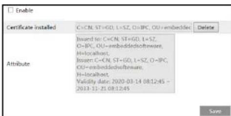
There is a certificate installed by default as shown above. Enable this function and save it. Then the device can be accessed by entering https://IP: https port via the web browser (eg. https://192.168.226.201:443).
A private certificate can be created if users don't want to use the default one. Click "Delete" to cancel the default certificate. Then the following interface will be displayed.

* If there is a signed certificate, click "Browse" to select it and then click "Install" to install it.
* Click "Create a private certificate" to enter the following creation interface.
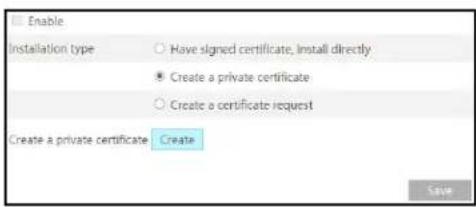
Click the "Create" button to create a private certificate. Enter the country (only two letters available), domain (device's IP address/domain), validity date, password, province/state, region and so on. Then click "OK" to save the settings.
* Click "Create a certificate request" to enter the following interface.

Click "Create" to create the certificate request. Then download the certificate request and submit it to the trusted certificate authority for signature. After receiving the signed certificate, import the certificate to the device.
5.5.13 QoS
QoS (Quality of Service) function is used to provide different quality of services for different network applications. With the deficient bandwidth, the router or switch will sort the data streams and transfer them according to their priority to solve the network delay and network congestion by using this function.
Go to Config→Network→QoS.
| Video/Audio DSCP | 13 |
| Alarm DSCP | 35 |
| Manager DSCP | 53 |
Video/Audio DSCP: The range is from 0 to 63.
Alarm DSCP: The range is from 0 to 63.
Manager DSCP: The range is from 0 to 63.
Generally speaking, the larger the number is, the higher the priority is.
5.5.14 TS Multicast
By using transport stream multicast (TS Multicast), multiple users can view the video image simultaneously even if there is not enough bandwidth.

Multicast address: the multicast IP address of Main Stream/Sub Stream/Third Stream ranges from 224.0.0.0 to 239.255.255.255.
Port: Main stream:2000; sub stream:2001; third stream:2002
Main stream: The address format is "udp://@IP address: main stream port."
Sub stream: The address format is "udp://@IP address: sub stream port."
Third stream: The address format is "udp://@IP address: third stream port."
Audio: if enabled, the video and audio will play automatically.
For example: you can test the TS multicast by using a VLC player. Enter the TS multicast address (eg. udp://@239.1.0.1:2001) in a VLC player.
Note: The TS multicast user also will be counted as an online user. You can go to Config→Security→Online User to view.
5.6 Security Configuration
5.6.1 User Configuration
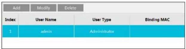
Go to Config→Security→User interface as shown below.
Add user:
- Click the "Add" button to pop up the following textbox.

- Enter user name in the "User Name" textbox.
- Enter the password in the "Password" and "Confirm Password" textbox. Please set the password according to the requirement of the password security level (Go to Config→Security→Security Management→Password Security interface to set the security level).
- Choose the user type and select the desired user permissions.
- Click the "OK" button and then the newly added user will be displayed in the user list.
Modify user:
- Select a user to modify password if necessary, in the user configuration list box.
- The "Edit user" dialog box pops up by clicking the "Modify" button.

- Enter the old password of the user in the "Old Password" text box.
- Enter the new password in the "New password" and "Confirm Password" text box.
- Select the user permissions for advanced or normal user.
- Click the "OK" button to save the settings.
Note: When the password level is set to "Strong", the password cannot be modified the same as the previous five.
Delete user:
- Select the user to be deleted in the user configuration list box.
- Click the "Delete" button to delete the user.
Note: The default administrator account cannot be deleted.
Safety Question Settings: Set the questions and answers for admin so as to reset the password after you forget the password.
5.6.2 Online User
Go to Config→Security→Online User to view the user who is viewing the live video.

An administrator user can kick out all the other users (including other administrators).
5.6.3 Block and Allow Lists
Go to Config→Security→Block and Allow Lists as shown below.

The setup steps are as follows:
Check the "Enable address filtering" check box.
Select "Block/Allow the following address", IPv4/IPv6 and then enter IP address in the address box and click the "Add" button.
5.6.4 Security Management
Go to Config→Security→Security Management as shown below.

In order to prevent against malicious password unlocking, "locking once illegal login" function can be enabled here. If this function is enabled, login failure after trying five times will make the login interface locked. The device can be logged in again after a half hour or after the device reboots.
Trigger Email: if enabled, e-mail will be sent when logging in/out or illegal login lock occurs.
- Password Security

Please set the password level and expiration time as needed.
Password Level: Weak, Medium or Strong.
Weak level: Numbers, special characters, upper or lower case letters can be used. You can choose one of them or any combination of them when setting the password.
Medium Level: 8\~16 characters, including at least two of the following categories: numbers, special characters, upper case letters and lower case letters.
Strong Level: 8\~16 characters. Numbers, special characters, upper case letters and lower case letters must be included.
For your account security, it is recommended to set a strong password and change your password regularly.
- HTTP Authentication: Basic or Token is selectable.
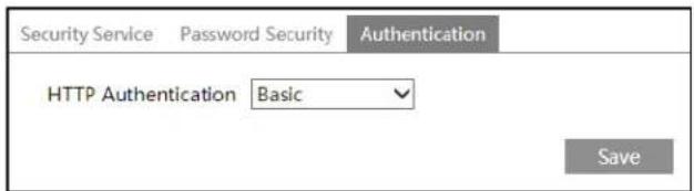
5.7 Maintenance Configuration
5.7.1 Backup and Restore
Go to Config→Maintenance→Backup & Restore.

- Import & Export Settings
Configuration settings of the device can be exported from a device into another device.
- Click "Browse" to select the save path for import or export information on the PC.
- Click the "Import Setting" or "Export Setting" button.
Note: The login password needs to be entered after clicking the "Import Setting" button.
- Default Settings
Click the "Load Default" button and then verify the password to restore all system settings to the default factory settings, except the image settings (see 5.2 Image Configuration) you want to keep.
5.7.2 Reboot
Go to Config→Maintenance→Reboot.
Click the "Reboot" button and then enter the password to reboot the device.

Timed Reboot Setting:
If necessary, the device can be set up to reboot on a time interval. Enable "Time Settings", set the date and time, click the "Save" button and then enter the password to save the settings.
5.7.3 Upgrade
5.7.3.1 Upgrading on the Web Interface
On the Web interface, go to Config→Maintenance→Upgrade. In this interface, the device firmware can be updated.

- Click the "Browse" button to select the save path of the upgrade file
- Click the "Upgrade" button to start upgrading the firmware.
- Enter the correct password and then the device will restart automatically
Caution! Do not close the browser or disconnect the device from the network during the upgrade.
5.7.3.2 Upgrading the Firmware Using GV-IP Device Utility
Optionally use GV-IP Device Utility (V8.9.8 or later) to upgrade the firmware. Note that the computer used to upgrade firmware must be under the same network as the video server.
- Make sure the PC and the video server are connected to the LAN, and GV-IP Device Utility (V8.9.8 or later) is installed on the PC from our website.
- On GV-IP Device Utility window, click the 🔒 button to search for the IP devices in the same LAN. Click the Name or Mac Address column on its IP address and select Configure.
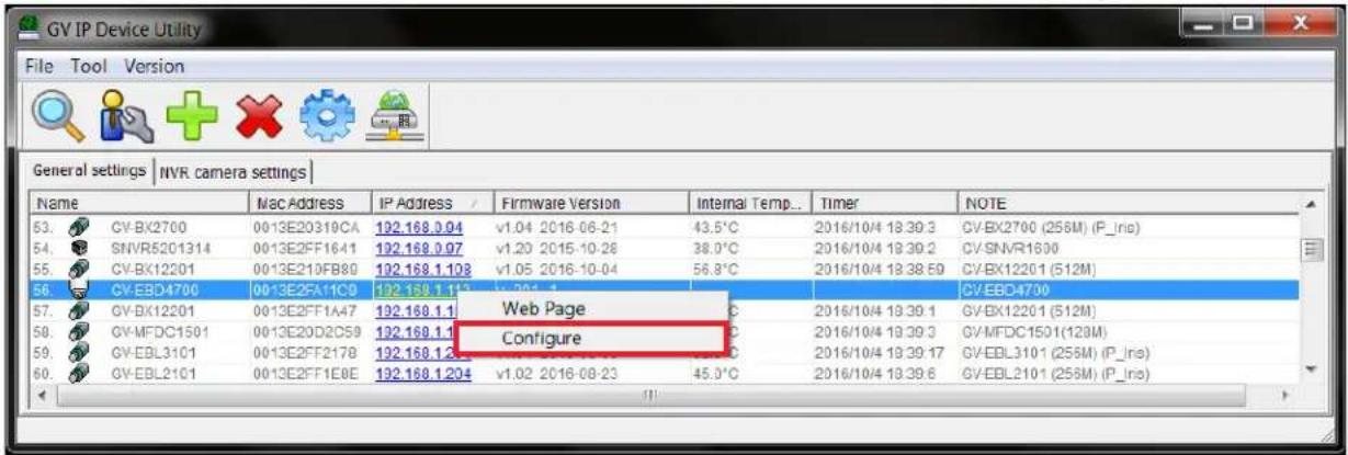
- Type the video server's user name and password to log in.
- Click the Firmware Upgrade tab. This dialog box appears.
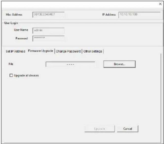
- Click Browse to locate the firmware file saved at your local computer.
- Click Upgrade to start upgrading the firmware.
5.7.4 Operation Log
To query and export log:
- Go to Config→Maintenance→Operation Log.
| Main Type Operation Sub Type Log in Start Time 2021-09-06 00:00.00 End Time 2021-09-06 23.59.59 Search Export | ||||||
| Index | Time | Main Type | Sub Type | User Name | Login IP | Hostname |
| 1 | 2021-09-06 03:1... | Operation | Log in | admin | 10.20.52.7 | |
| 2 | 2021-09-06 03:1... | Operation | Log in | admin | 10.20.52.7 | |
- Select the main type, sub type, start and end time.
- Click "Search" to view the operation log.
- Click "Export" to export the operation log.
Chapter 6. Search
6.1 Image Search
Click Search to go to the interface as shown below. Images that are saved on the SD card can be found here.
Note: When using the plug-in free browser, the local images cannot be searched.
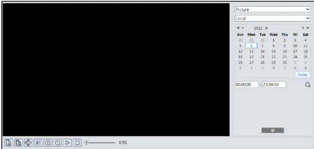
- Local Image Search
- Choose "Picture"—"Local".
- Set time: Select date and choose the start and end time.
- Click to search the images.
- Double click a file name in the list to view the captured photos as shown above.

Click to return to the previous interface.
- SD Card Image Search
- Choose "Picture"—"SD Card".
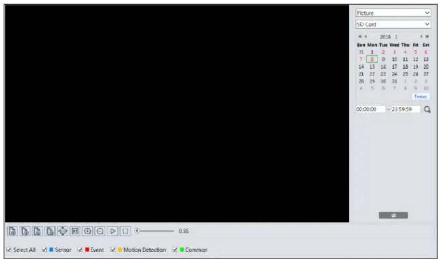
- Set time: Select date and choose the start and end time.
- Choose the alarm events at the bottom of the interface.
- Click to search the images.
- Double click a file name in the list to view the captured photos.
Click to return to the previous interface.
The descriptions of the buttons are shown as follows.
| Icon | Description | Icon | Description |
 | Close: Select an image and click this button to close the image. | Close all: Click this button to close all images. | |
 | Save: Click this button to select the path for saving the image on the PC. | Save all: Click this button to select the path for saving all pictures on the PC. | |
 | Fit size: Click to fit the image on the screen. | Actual size: Click this button to display the actual size of the image. | |
 | Zoom in: Click this button to digitally zoom in. | Zoom out: Click this button to digitally zoom out. | |
 | Slide show play: Click this button to start the slide show mode. | Stop: Click this button to stop the slide show. | |
 | Play speed: Play speed of the slide show. | ||
6.2 Video Search
6.2.1 Local Video Search
Click Search to go to the interface as shown below. Videos were recorded locally to the PC can be played in this interface.
Note: When using the plug-in free browser, the local videos cannot be searched.

- Choose "Record"—"Local".
- Set search time: Select the date and choose the start and end time.
- Click to search the images.
- Double click on a file name in the list to start playback.

| Icon | Description | Icon | Description | |
| [WC46] | Play button. After pausing the video, click this button to continue playing. | Pause button | ||
 | Stop button | Speed down | ||
| [SAZZ] | Speed up | Watermark display | ||
 | Enable / disable audio; drag the slider to adjust the volume after enabling audio. | |||
6.2.2 SD Card Video Search
Click Search to go to the interface as shown below. Videos that were recorded on the SD card can be played in this interface.
- Choose "Record"—"SD Card".
- Set search time: Select the date and choose the start and end time.
- Click to search the images.

- Select the alarm events at the bottom of the interface.
-
Select mix stream (video and audio stream) or video stream as needed.
-
Double click on a file name in the list to start playback.

Note:
- 1.◀ and ▶ cannot be displayed in the above interface via the plug-in free browser.
- For plug-in free playback, playback mode switch (balanced/real-time/fluent mode) and downloading functions are not supported too.
- For the fluent playback, it is recommended to use the plug-in required browser to play the recorded file whose resolution exceeds 2MP.
The time table can be shown in 24H/12H/2H/1H format by clicking the corresponding buttons.
Video clip and downloading
- Search the video files according to the above-mentioned steps.
- Select the start time by clicking on the time table.
- Click 🎨 to set the start time and then this button turns blue (💡).
- Select the end time by clicking on the time table. Then click to set the end time.
- Click to download the video file in the PC.

Click "Set up" to set the storage directory of the video files.
Click "Open" to play the video.
Click "Clear List" to clear the downloading list.
Click "Close" to close the downloading window.
Appendix
Troubleshooting
How to find the password?
A: The password for admin can be reset through "Edit Safety Question" function.
Click "Forget Password?" on the login page and enter the corresponding answer of the selected question in the popup window. After you correctly answer all questions, you can reset the password for admin. If you forget the answer of the question, this way will be invalid, please contact your dealer for help.
B: The passwords of other users can be reset by admin.
Fail to connect devices through IE browser.
A: Network is not well connected. Check the connection and make sure it is connected well.
B: IP address is not available. Reset the IP address.
C: Web port number has been changed: contact administrator to get the correct port number.
D: Exclude the above reasons. Restore to default setting by IP-Tool.
IP tool cannot search devices.
It may be caused by the anti-virus software in your computer. Please exit it and try to search device again.
IE cannot download the plug-in.
A. IE browser may be set up to block plug-ins. Follow the steps below.
- Open IE browser and then click Tools→Internet Options.
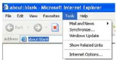
-
Select Security→Custom Level.
-
Enable all the options under the plug-ins.
-
Click OK to finish setup.
B. Other plug-ins or anti-virus blocks the plug-in. Please uninstall or close them.

No sound can be heard.
A: Audio input device is not connected. Please connect and try again.
B: Audio function is not enabled at the corresponding channel. Please enable this function.
- © 2023 GEOVISION, INC. ALL RIGHTS RESERVED
- TABLE OF CONTENTS
- CHAPTER 1. INTRODUCTION.... 1
- CHAPTER 2. INTRODUCTION....7
- CHAPTER 3. NETWORK CONNECTION....9
- CHAPTER 4. LIVE VIEW....16
- CHAPTER 5. NETWORK CAMERA CONFIGURATION....19
- 5.5 NETWORK CONFIGURATION....54
- 5.6 SECURITY CONFIGURATION....66
- 5.7 MAINTENANCE CONFIGURATION....70
- CHAPTER 6. SEARCH....74
- 6.1 IMAGE SEARCH....74
- 6.2 VIDEO SEARCH....77
- APPENDIX....80
- CHAPTER 1. INTRODUCTION
- SAFETY INSTRUCTION
- ABOUT THE MANUAL
- USE OF THE PRODUCT
- ELECTRICAL SAFETY
- ENVIRONMENT
- OPERATION AND DAILY MAINTENANCE
- PRIVACY PROTECTION
- DISCLAIMER
- CYBERSECURITY RECOMMENDATIONS
- REGULATORY INFORMATION
- FCC INFORMATION
- FCC COMPLIANCE
- FCC CONDITIONS
- ROHS
- CHAPTER 2. INTRODUCTION
- 2.1 MAIN FEATURES
- 2.2 CONNECTION
- NOTE
- CHAPTER 3. NETWORK CONNECTION
- SYSTEM REQUIREMENT
- 3.1 LAN
- 3.1.1 ASSIGNING AN IP ADDRESS USING GV-IP DEVICE UTILITY
- IMPORTANT
- 3.1.2 DIRECTLY ACCESS THROUGH IE
- 3.2 WAN
- ACCESS THROUGH PPPOE DIAL-UP
- ACCESS THROUGH STATIC IP
- CHAPTER 4. LIVE VIEW
- COC (/UTC) CONTROL
- VIDEO OUTPUT SWITCH
- LANGUAGE SELECTION
- CHAPTER 5. NETWORK CAMERA CONFIGURATION
- 5.1 SYSTEM CONFIGURATION
- 5.1.1 BASIC INFORMATION
- 5.1.2 DATE AND TIME
- 5.1.3 LOCAL CONFIG
- 5.1.4 STORAGE
- SD CARD MANAGEMENT
- SCHEDULE RECORDING SETTINGS
- WEEKLY SCHEDULE
- DAY SCHEDULE
- SNAPSHOT SETTINGS
- USB DISK
- 5.2 IMAGE CONFIGURATION
- 5.2.1 DISPLAY SETTINGS
- 5.2.2 VIDEO / AUDIO CONFIGURATION
- 5.2.3 OSD CONFIGURATION
- 5.2.4 VIDEO MASK
- 5.2.5 ROI CONFIGURATION
- 5.3 ALARM CONFIGURATION
- 5.3.1 MOTION DETECTION
- 5.3.2 EXCEPTION ALARM
- SD CARD FULL
- SD CARD ERROR
- IP ADDRESS COLLISION
- CABLE DISCONNECTION
- 5.3.3 ALARM IN
- 5.3.4 ALARM OUT
- 5.3.5 ALARM SERVER
- 5.4 EVENT CONFIGURATION
- 5.4.1 OBJECT ABANDONED/MISSING
- ※ THE CONFIGURATION REQUIREMENTS OF CAMERA AND SURROUNDING AREAS
- 5.4.2 VIDEO EXCEPTION
- ※ THE REQUIREMENTS OF CAMERA AND SURROUNDING AREA
- 5.4.3 LINE CROSSING
- DETECTION TARGET
- ※ CONFIGURATION OF CAMERA AND SURROUNDING AREA
- 5.4.4 REGION INTRUSION
- ※ CONFIGURATION REQUIREMENTS OF CAMERA AND SURROUNDING AREA
- 5.4.5 REGION ENTRANCE
- 5.4.6 REGION EXITING
- 5.4.7 TARGET COUNTING BY LINE
- 5.4.8 TARGET COUNTING BY AREA
- 5.4.9 FACE DETECTION
- FACE CAPTURE VIEW
- 5.4.10 HEAT MAP
- 5.5 NETWORK CONFIGURATION
- 5.5.1 TCP/IP
- 5.5.2 PORT
- 5.5.3 DDNS
- 5.5.4 SNMP
- 5.5.5 802.1X
- 5.5.6 RTSP
- MULTICAST ADDRESS
- 5.5.7 RTMP
- 5.5.8 UPNP
- 5.5.9 EMAIL
- 5.5.10 FTP
- 5.5.11 HTTP POST
- 5.5.12 HTTPS
- 5.5.13 QOS
- 5.5.14 TS MULTICAST
- 5.6 SECURITY CONFIGURATION
- 5.6.1 USER CONFIGURATION
- ADD USER
- MODIFY USER
- DELETE USER
- 5.6.2 ONLINE USER
- 5.6.3 BLOCK AND ALLOW LISTS
- 5.6.4 SECURITY MANAGEMENT
- PASSWORD SECURITY
- 5.7 MAINTENANCE CONFIGURATION
- 5.7.1 BACKUP AND RESTORE
- IMPORT & EXPORT SETTINGS
- DEFAULT SETTINGS
- 5.7.2 REBOOT
- TIMED REBOOT SETTING
- 5.7.3 UPGRADE
- 5.7.3.1 UPGRADING ON THE WEB INTERFACE
- 5.7.3.2 UPGRADING THE FIRMWARE USING GV-IP DEVICE UTILITY
- 5.7.4 OPERATION LOG
- CHAPTER 6. SEARCH
- 6.1 IMAGE SEARCH
- LOCAL IMAGE SEARCH
- SD CARD IMAGE SEARCH
- 6.2 VIDEO SEARCH
- 6.2.1 LOCAL VIDEO SEARCH
- 6.2.2 SD CARD VIDEO SEARCH
- VIDEO CLIP AND DOWNLOADING
- APPENDIX
- TROUBLESHOOTING
- HOW TO FIND THE PASSWORD
- FAIL TO CONNECT DEVICES THROUGH IE BROWSER
- IP TOOL CANNOT SEARCH DEVICES
- IE CANNOT DOWNLOAD THE PLUG-IN
- NO SOUND CAN BE HEARD
Brand : Geovision
Model : GV-GVS2100
Category : Digital Video Recorder