
Muro OD-M61T - Uncategorized ELAC - Free user manual and instructions
Find the device manual for free Muro OD-M61T ELAC in PDF.


| Product Type | 2-way sealed/ported design, indoor/outdoor on-wall speaker |
| Frequency Response (-3 dB) | 80 Hz – 20 kHz |
| Frequency Response (-6 dB) | 65 Hz – 20 kHz |
| Nominal Impedance | 8 Ω ±20% (Low-Z) |
| Sensitivity | 87.5 dB @ 2.83 V/1 m |
| Transformer Taps (100V) | 30 W, 15 W, 7.5 W |
| Transformer Taps (70V) | 30 W, 15 W, 7.5 W, 3.8 W |
| Recommended Amplifier Power | 30 – 150 W |
| Nominal/Peak Power Handling | 80 W / 130 W |
| Tweeter | 25 mm silk dome with 2-layer CCA voice coil |
| Woofer | 8 in (203 mm) polypropylene cone, rubber surround |
| Cabinet Material | UV-resistant plastic |
| Cabinet Finish | Black or White |
| Port | Sealed with optional port plugs for ported configuration |
| Weather Resistance | IP66 rated |
| Speaker Connection | 4-position Euroblock |
| Mounting | Wall, ceiling, and corner mount with included bracket; 15° increment alignment marks |
| Orientation | Horizontal or vertical (no impact on sound) |
| Safety Cable Attachment | U-bolt on rear of speaker |
| Dimensions (W x H x D) | 6.8 x 40.6 x 9.7 in (172 x 1030 x 246 mm) |
| Net Weight | 34.6 lbs (15.7 kg) |
| Warranty | 3 years (North America, parts and labor) |
Frequently Asked Questions - Muro OD-M61T ELAC
User questions about Muro OD-M61T ELAC
0 question about this device. Answer the ones you know or ask your own.
Ask a new question about this device
Download the instructions for your Uncategorized in PDF format for free! Find your manual Muro OD-M61T - ELAC and take your electronic device back in hand. On this page are published all the documents necessary for the use of your device. Muro OD-M61T by ELAC.
USER MANUAL Muro OD-M61T ELAC
MODELS : OD-M61T, OD-M81T
natural_image
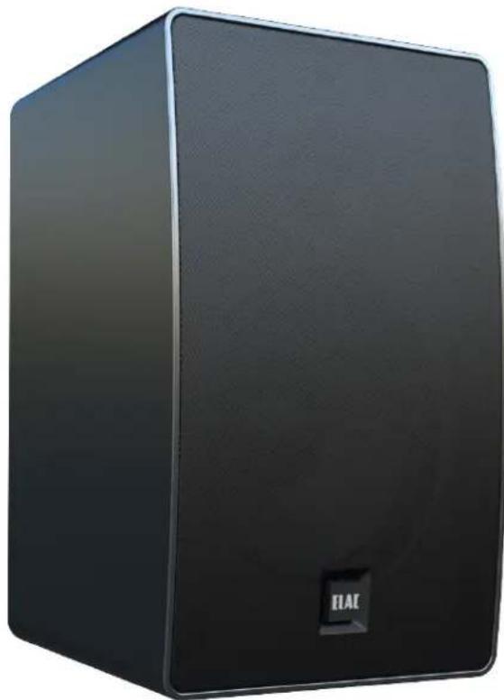
Black rectangular speaker with ELAE logo, no visible text or symbols on body70/100V INDOOR/OUTDOOR SPEAKER
OWNER'S MANUAL
ELAC
The life of sound.
Thank you, and Congratulations on bringing home an ELAC Muro Pro speaker.
WALL-MOUNTED
Sound with Style and Strength
Introducing the new ELAC Muro Pro Outdoor On-Wall Speaker, where modern design meets exceptional versatility. Featuring a clean, sleek profile with no large visible knobs, this speaker seamlessly integrates into any environment, indoors or outdoors. Engineered for durability, it boasts an IP66 rating to withstand the elements, while removable port plugs allow you to transform its design into a ported configuration for enhanced bass performance when weather conditions permit. With its refined aesthetics and innovative functionality, the Muro Pro Outdoor On-Wall Speaker is the perfect blend of style, adaptability, and premium sound quality.
Enjoy!
JOURNEY TOGETHER THROUGH - THE LIFE OF SOUND
WHAT'S INCLUDED

PRODUCT FEATURES

Avoid damage to the speakers and other components:
- Unbox the speakers carefully to avoid physically damaging your speakers.
- Use appropriate gauge wires
- Make sure wire polarity is connected correctly. Most speaker cables are coded for ease of use. Make sure positive (red) connection on the amplifier terminal is connected to the positive (red) on your speakers.
• Follow the same instructions for the negative side. - Strip off approximately 12 " of the insulation from the ends of the speaker cable, twist the bare strands and insert into the Euroblock
- Ensure your equipment is turned off before connecting speakers.
- Check to ensure positive and negative wires are not touching each other once they're connected to the speaker terminals.


Wire Recommendation
The gauge of the wire significantly affects the performance of your speakers. For optimal results, use multi-stranded wire specifically designed for amplifier-to-speaker connections.
When selecting the wire gauge, consider the length of the wire run to each speaker. Longer wire runs require larger gauge wire to maintain performance and minimize signal loss.
| WIRE GAUGE CHART | |
| WIRE GAUGE DISTANCE | |
| 18 Gauge Up to 100 feet (30 meters) | |
| 16 Gauge Up to 150 feet (45 meters) | |
| 14 Gauge Up to 250 feet (80 meters) | |
| 12 Gauge Up to 400 feet (122 meters) | |
| 10 Gauge Up to 650 feet (198 meters) |
WEATHER RESISTANCE AND DURABILITY
- The ELAC Muro Pro speakers are IP66 rated, ensuring they are weather-resistant and capable of delivering exceptional performance for years, even in challenging outdoor environments.
MOUNTING FLEXIBILITY
- The included bracket system allows for easy installation of the speakers in various positions and locations to suit your needs.
OPTIMAL PLACEMENT
- For the best sound performance, place the speakers at ear level, facing the listener.
- If the speakers must be mounted above or below ear level, pivot them up or down to direct the sound toward the listener.
ORIENTATION OPTIONS
- The speakers can be oriented horizontally or vertically without any impact on sound quality, giving you flexibility in how you install them.
By following these recommendations, you can enjoy the full audio potential of your ELAC Muro speakers in any outdoor setting.
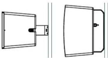
WALL/CEILING MOUNT INSTRUCTIONS

natural_image
Simple line drawing of a handbag with handle and side panel (no text or symbols)Ceiling Mount
natural_image
Technical line drawing of two mechanical components with no visible text or symbolsWall Mount

Corner Mount
To ensure safe and secure installation, follow these guidelines when mounting your speaker:
SECURE MOUNTING SURFACE
- The bracket must be attached to a structurally sound surface that can support the weight of the speaker and withstand vibrations during operation.
SCREW REQUIREMENTS
• Always use two screw points for mounting.
• Recommended screw sizes:
- #14 to #20 diameter x 2" length
• M6 to M8 diameter x 50mm length
SURFACE-SPECIFIC INSTALLATION
- For drywall or plasterboard, secure the bracket to a joist or stud.
- For brick or concrete, use wall plugs or concrete anchors to ensure stability.
SAFETY PRECAUTION
- Attach a safety cable to the U-bolt on the back of the speaker for additional security.
- You can rotate the speaker in the bracket to direct the sound towards the listeners.
- Loosen the side bolts on the speaker
- Rotate the speakers to the desired position.
- Lock the side bolts on the speaker

natural_image
Line drawing of a rectangular electronic device with a handle and internal components (no text or symbols)
natural_image
Diagram showing three types of screws and a vertical screw, enclosed in a circle (no text or symbols)
natural_image
Technical line drawing of a device rear panel with internal components and mounting brackets (no text or symbols)Route wire through grommet and tighten grommet to create a seal.
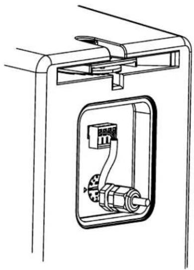
natural_image
Technical line drawing of a mechanical assembly with internal components (no text or symbols)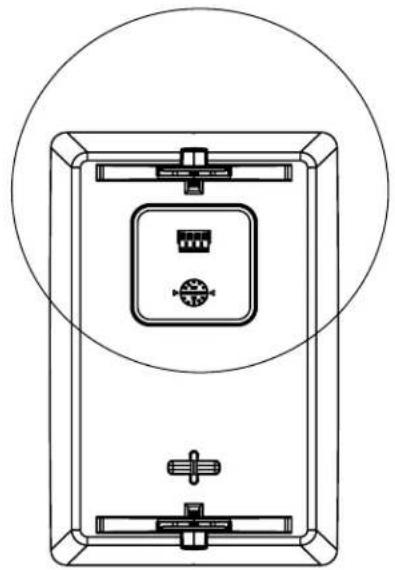
natural_image
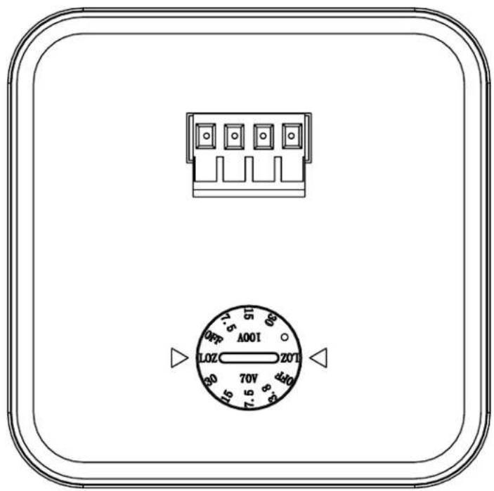
Technical line drawing of a rectangular device with internal components and mounting brackets, enclosed in a circle (no text or symbols)Tap settings for 70/100Volt located behind rear cover
natural_image
Technical line drawing of a mechanical device with mounting bracket and circular outline (no text or symbols)Mounting screw to bracket inserted through shoulder mount.

natural_image
Technical line drawing of a mechanical assembly with a bolt, housing, and mounting bracket (no text or symbols)
natural_image
Technical line drawing of a mechanical component with mounting holes and a central shaft (no text or symbols)Shoulder mount has marking in 15 degrees increments facilitating alignment of multiple speakers.

natural_image
Technical line drawing of a mechanical device with no visible text or symbols
natural_image
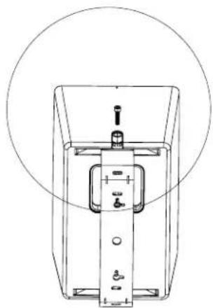
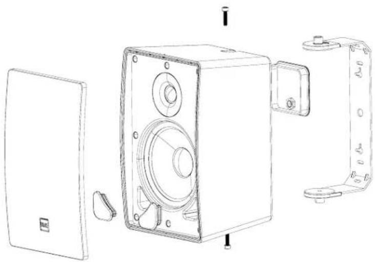
Line drawing of a mechanical component with a circular hole and base plate (no text or symbols)Remove the Grille locking screw on top and bottom of speaker to gain access to the front of the speaker.
natural_image
Technical line drawing of a speaker chamber with mounting bracket and side panel (no text or symbols)Removable port plugs transform the design into a ported configuration for enhanced bass performance when weather conditions permit.

The 70/100-Volt tap allows you to adjust the power level for your speaker in distributed audio systems. CHOOSE THE DESIRED WATTAGE
- Rotate the dial or adjust the switch to the wattage setting appropriate for your system's power requirements. Available wattage options will typically be marked (e.g., 3.8W, 7W, 15W).
SETTING 70/100-VOLT TAPS WITHOUT EXCEEDING AMPLIFIER POWER RATING
- When configuring a distributed audio system, it's essential to ensure the total power draw of the speakers does not exceed the amplifier's power rating. Follow these steps:
CHOOSE THE DESIRED WATTAGE
- Identify the amplifier's maximum power output (e.g., 120W, 250W).
- Add up the wattage settings (taps) of all speakers in the system.
• Example: If you have four speakers set to 20W each, the total load is 80W. - Adjust each speaker's tap setting to ensure the total combined wattage does not exceed the amplifier's power rating
- To avoid overloading, leave a 10 - 20% safety margin below the amplifier's maximum power.
• Example: For a 120W amp, keep the total speaker load below 100-110W.
| OD-M61T OD-M81T | ||
| SPEAKER TYPE 2-WAY SEALED/PORTED DESIGN | ||
| FREQUENCY RESPONSE -3 dB: 80 TO 20KHz 70 TO 20KHz | ||
| FREQUENCY RESPONSE -6 dB: 65 TO 20KHz 55 TO 20KHz | ||
| TRANSFORMER TAP | 100V 8Ω * 30W 15W 7.5W70V 8Ω 30W 15W 7.5W 3.8W | 100V 8Ω * 60W 30 15W70V 8Ω 60W 30W 15W 7.5W |
| NOMINAL IMPEDANCE 8Ω ±20% @ LOW-Z | 8Ω ±20% @ LOW-Z | |
| SENSITIVITY @2.83 V/1M 87.5 dB 87.5 dB | ||
| CROSSOVER FREQUENCY 500 Hz, 2100 Hz 550 Hz, 2000 Hz | ||
| RECOMMENDED AMPLIFIER POWER 30 - 150 W | 30 - 180 W | |
| NOMINAL/PEAK POWER HANDLING | 80/130 W | 100/150 W |
| TWEETER | 25mm Silk Dome Tweeter with 2-layer Copper-Clad Aluminum Voice Coil | |
| WOOFER (ARAMID-FIBER) 8 " 25MM POLYPROPYLENE CONE, RUBBER SURROUND | ||
| CABINET | UV-Resistant Plastic | |
| CABINET FINISH | Black - White | |
| PORT | Sealed with Option for Ported Design | |
| SPEAKER CONNECTION | 4 Position Euroblock | |
| WIDTH (IN / MM) | 6.8/172 | 7.7/195 |
| HEIGHT (IN / MM) | 40.6/1030 | 43.1/1094 |
| DEPTH (IN / MM) | 9.7/246 | 10.6/268 |
| Net Weight (lbs / KG) | 34.6/15.7 | 38.8/17.6 |
ELAC Americas Inc.
North America Limited Liability Warranty
ELAC Americas Inc. warrants to the original purchaser that this product be free from defects and or workmanship for a period of 3 (Three) years from the original date of purchase. During this time period, repair or replacement of parts will be free of charge to the original owner (See below limitations). Shipping to and return from the repair center will be the responsibility of the original purchaser.
Limitations
- Warranty begins on the date of original purchase from an authorized ELAC Americas Inc. dealer.
- Product is warranted only if used in home applications within the max power rating specified in this manual. Commercial use of this product is not warranted.
- Product that has been modified or altered in anyway will not be warranted.
- Product that has been abused or subjected to faulty equipment will not be warranted.
- Products with defaced or removed serial numbers will not be warranted.
If service is required
In the event that service is required, please contact ELAC America at 888-541-0996 or at customerservice@elac.us to arrange for service or replacement. You will be responsible to provide proof of purchase (Copy or original sales receipt). Shipping to and from our repair center will be the responsibility of the original purchaser.
Warranty Outside of North America
This warranty applies to products purchased in the United States and Canada. For warranty claims outside of North America please contact the local dealer/distributor in the country of purchase.

ELAC
The life of sound.
ELAC AMERICAS INC.
1938 N. BATAVIA St. SUITE K
ORANGE, CA 92865
ELAC ELECTROACUSTIC GMBH
FRAUNHOFERSTRAße 16
D-24118 KIEL, GERMANY
- ELAC
- WALL-MOUNTED
- Sound with Style and Strength
- WHAT'S INCLUDED
- PRODUCT FEATURES
- Wire Recommendation
- WEATHER RESISTANCE AND DURABILITY
- MOUNTING FLEXIBILITY
- OPTIMAL PLACEMENT
- ORIENTATION OPTIONS
- WALL/CEILING MOUNT INSTRUCTIONS
- SECURE MOUNTING SURFACE
- SCREW REQUIREMENTS
- SURFACE-SPECIFIC INSTALLATION
- SAFETY PRECAUTION
- Limitations
- If service is required
- Warranty Outside of North America
Brand : ELAC
Model : Muro OD-M61T
Category : Uncategorized