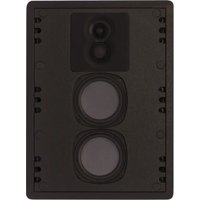
CI120 - Enceinte acoustique encastrable Phase Technology - Free user manual and instructions
Find the device manual for free CI120 Phase Technology in PDF.


| Product Type | Dual 5.25" 3-Way In-Wall Speaker with Patented Clamping System |
| Model | CI120 |
| Brand | Phase Technology |
| Nominal Impedance | 4 Ω |
| Sensitivity | 88 dB |
| Frequency Response | 50 Hz - 22 kHz |
| Recommended Power | 20 - 150 Watts |
| Tweeter | 1" Soft Dome with Unicell Acoustic Treatment |
| Midrange | 1.5" Soft Dome with Unicell Acoustic Treatment |
| Woofer(s) | (2) 5.25" RPF Flat-Piston Fiberglass & Kevlar Composite Cone with NBR Surround |
| Inputs | Screw Terminal |
| Grille | White Powder-Coated Galvanized Magnetic Micro-Flange (paintable) |
| Dimensions (H x W x D) | 19.25" x 14.25" x 3.875" |
| Cutout Dimensions (H x W) | 18.125" x 13.25" |
| Weight | 20 lbs |
| Optional Accessories | Rough-In Bracket (RB-24) |
| Protection Circuit | Self-resetting solid-state PTC protection |
| Mounting System | Patented self-aligning clamping system |
| Warranty | Limited lifetime for CI speakers (original purchaser) |
| Recommended Wire | 16 gauge or heavier |
| Installation Requirements | Drywall saw or knife, stud-finder, bubble level, screwdriver |
Frequently Asked Questions - CI120 Phase Technology
User questions about CI120 Phase Technology
0 question about this device. Answer the ones you know or ask your own.
Ask a new question about this device
Download the instructions for your Enceinte acoustique encastrable in PDF format for free! Find your manual CI120 - Phase Technology and take your electronic device back in hand. On this page are published all the documents necessary for the use of your device. CI120 by Phase Technology.
USER MANUAL CI120 Phase Technology
BY MSE AUDIO
CI IN-WALL
OWNER'S MANUAL: CI120 • CI130
![[BOX CONTENTS] 1 SPEAKER 1 MICRO-FLANGE GRILLE 1 MOUNTING FLANGE ASSEMBLY 1 HOLE TEMPLATE GRILLE SELF-ALIGNING CLAMPING SYSTEM FLANGEASSEMBLY SPEAKER REAR ENCLOSURE FLANGEASSEMBLY GRILLE SPEAKER/ BAFFLE ASSEMBLY](/content/2026/05/1095179/images/64e70ef15ce11cfbe5573148e7f6b3ef532c768e63cb40dff91569842eda2e43.jpg)
[GETTING STARTED] FOR EFFICIENT INSTALLATION, YOU WILL NEED THE FOLLOWING TOOLS: • ELECTRIC SCREWDRIVER (DRILL) WITH PHILIPS BIT • TAPE MEASURE • STUD-FINDER • 3/32" STANDARD SCREWDRIVER • DRYWALL SAW OR KNIFE • BUBBLE LEVEL • PENCIL
Thank you for purchasing the Phase Technology® CI Custom Installation high definition in-wall speaker system. The mounting frame of extruded aluminum has a uniquely designed self-aligning clamping system to secure the flange assembly to the drywall. This patented design simplifies installation and reduces unwanted wall vibration resulting in improved performance and definition.
All CI Series speakers include self-resetting solid-state PTC protection circuits. This unique system is able to detect when the speaker is being over-driven and lowers the speaker volume until the problem is corrected. The PTC device then resets itself for normal operation.
Regardless of application, serious audiophile listening or home theater, we recommend that you take the time to read this manual thoroughly before connecting speakers to your amplifier or receiver. In the highly unlikely event that you should experience a problem with set-up or operation, please contact one of our authorized dealers for assistance, or contact us directly.
Phase Technology ^® Corporation
8005 W. 110th St., Suite 208, Overland Park, KS 66210
855.663.5600 (Domestic)
+1.913.663.5600 (International)
913.663.3200 (Fax)
SAFETY INSTRUCTIONS
INSTALLATION GUIDELINES
SPEAKER INSTALLATION
CARING FOR YOUR SPEAKER
MAINTENANCE AND SERVICE
WARRANTY
SPECIFICATIONS
[SAFETY INSTRUCTIONS]
![Phase Technology CI120 - [SAFETY INSTRUCTIONS] - 1](/content/2026/05/1095179/images/0aa660413d055c18aa2f70ac70072222152046ce16d2c8679276142dcdea0a88.jpg)
CAUTION
RISK OF ELECTRIC SHOCK
DO NOT OPEN
![Phase Technology CI120 - [SAFETY INSTRUCTIONS] - 2](/content/2026/05/1095179/images/432a3e48dbdb89ffc35a951b376d354d50824006a15d224c47aa93f1687da88e.jpg)
CAUTION: To reduce the risk of electric shock, do not remove cover (or back). No user-serviceable parts inside. Refer servicing to qualified service personnel.
Explanation of Graphical Symbols

The lightning flash with arrowhead symbol, within an equilateral triangle, is intended to alert you to the presence of un-insulated “dangerous voltage: within the product’s enclosure that may be off sufficient magnitude to constitute a risk of electric shock to persons.

The exclamation point within an equilateral triangle is intended to alert you to the presence of important operating and maintenance (servicing) instructions in the literature accompanying the appliance.
- Read Instructions - All the safety and operating instructions should be read before the appliance is operated.
- Retain Instructions - The safety and operating instructions should be retained for future reference.
- Heed Warnings - All warnings on the appliance and in the operating instructions should be adhered to.
- Follow Instructions - All operating and other instructions should be followed.
- Water and Moisture - The appliance should not be used near water - for example, near a bathtub, washbowl, kitchen sink, laundry tub, in a wet basement, or near a swimming pool, etc.
- Carts and Stands - The appliance should be used only with a cart or stand that is recommended by the manufacturer.
PORTABLE CART WARNING

- Wall or Ceiling Mounting - The appliance should be mounted to a wall or ceiling only as recommended by the manufacturer.
- Ventilation - The appliance should be situated so that its location or position does not interfere with its proper ventilation. For example, the appliance should not be situated on a bed, sofa, rug, or similar surface that may block the ventilation openings; or placed in a built-in installation, such as a bookcase or cabinet
that may impede the flow of air through the ventilation openings.
- Heat - The appliance should be situated away from heat sources such as radiators, stoves, or other appliances that produce heat.
- Power Source - The appliance should be connected to a power supply only of the type described in the operating instructions or as marked on the appliance.
- Power Cord Protection - Power supply cords should be routed so that they are not likely to be walked on or pinched by items placed up or against them, paying particular attention to cords at plugs, convenience receptacles, and the point where they exit from the appliance.
- Cleaning - The appliance should be cleaned only as recommended by the manufacturer.
- Nonuse Periods - The power cord of the appliance should be unplugged from the outlet when left unused for a long period of time.
- Object and Liquid Entry - Care should be taken so that neither objects fall nor liquids spill into the inside of the appliance.
- Damage Requiring Service - The application should be serviced by qualified service personnel when:
a. the power supply cord or the plug has been damaged,
b. objects have fallen onto or liquid has been spilled into the appliance,
c. the appliance has been exposed to rain,
d. the appliance does not appear to operate normally or exhibits a marked change in performance, or
e. the appliance has been dropped or the cabinet damaged.
- Servicing - The user should not attempt to service the appliance beyond those means described in the operating instructions. All other servicing should be referred to qualified service personnel.
- Grounding or Polarization - Precautions should be taken so that the grounding or polarization means of an appliance is not defeated.
APPLICABLE FOR USA, CANADA OR WHERE APPROVED FOR USAGE
CAUTION: TO PREVENT ELECTRIC SHOCK, MATCH WIDE BLADE PLUG TO WIDE SLOT, INSERT FULLY.
ATTENTION: POUR EVITER LES CHOCS ELECTRIQUES, INTRODUIRE LA LAME LA PLUS LARGE DE LA FICHE DANS LA BORNE CORRESPONDANTE DE LA PRESE ET POUSSER JUSQU AU FOND.
[INSTALLATION GUIDELINES]
When selecting the speaker mounting location, it is prudent to take a few extra minutes to carefully inspect and measure the wall or ceiling area where you intend to mount the CI in-wall speaker. An inspection of the room or rooms that back-up to the wall you have selected for mounting the CI in-wall speaker, can often alert you to potential obstacles. For example, if the wall you want to mount into happens to be the common wall for a bathroom or kitchen, there is a good chance you will encounter water or sewer pipes in the wall that will not be detected by a stud-finder. An electronic stud-finder is a useful tool to assist you in selecting the speaker placement, however be cautious as they often give false readings.
Choose the appropriate mounting location for each speaker.
NOTE: When deciding upon a location, consider the following:
- Be certain your speaker wires can be run to or are accessible from these locations.
- Make certain the wall or ceiling material is sturdy enough to support the weight and vibration of the speakers.
- It is recommended that our pre-construction rough-in brackets be used whenever possible in new construction.
- Be certain the area behind the speaker is free of obstacles such as wall studs, electrical wiring, pipes, etc.
• Each speaker should be positioned properly, relative to the listening area for good coverage. - Audio performance and room-to-room isolation will be improved if there is some fiberglass insulation placed loosely above and below the speaker.
[SPEAKER INSTALLATION]
STEP 1: The cutout opening for the Cl120 is 18.125" H x 13.25" W; Cl130 is 22.375" H x 13" W. Place the cutout template against the wall surface and align it using your bubble level and tape measure. Hold, tape or staple the template in place and trace around the perimeter of the template with a pencil. Remove the template and begin cutting on the pencil line.
STEP 2: When the cutout is complete, carefully remove the drywall piece from the opening. You now have a large opening to facilitate pulling your speaker wire. We recommend 16 gauge or heavier wire be used with the CI speaker. Contact your Phase Technology® Dealer for a recommendation.
STEP 3: Carefully remove the speaker baffle from the aluminum frame assembly and set aside. Remove the flange assembly from the packing carton. The flange assembly must make a good seal to insure maximum performance. You will find two L-shaped foam gasket pieces in the bottom of the carton. Peel the removable tape from the gasket and stick the adhesive side to the backside of the frame flange. Upon installation of the flange assembly gasket will contact the front wall surface to form an airtight seal.
STEP 4: When you remove the flange assembly from the packing carton, you will notice the screws used to retain the clamp assembly are fully extended. To place the flange assembly into the wall push the clamp assemblies toward the center of the flange opening; the holes in the flange will allow the mounting screws to tilt toward the center opening enough to insert the flange assembly into the wall. Insert the right side into the wall cutout and slide the complete assembly to the right. This will enable you to then fit the left side clamp assembly into the cutout. Center the entire assembly in the opening.
STEP 5: Pinch the self-aligning clamp assembly inside the wall until it contacts the backside of the drywall surface. This will force the three retaining screws to protrude from the front of the flange. Continue to hold the clamp with one hand and use the electric screwdriver to tighten the center screw of the flange. Once snug, repeat the procedure on the other clamp assembly. Using your level, verify the mounting frame is correctly aligned in the opening. Make any necessary adjustments then tighten the remaining screws until the frame is snug and securely clamping the wallboard. Avoid over-tightening the screws.
STEP 6: You are now ready to install the speaker baffle into the mounting flange.
CI120: The CI120 has a nylon terminal block on the top end of the enclosure. Connect your speaker lead wire to the terminal block and secure the stripped ends of your speaker wire by tightening down the screw terminals, the red wire to the positive and the black to the negative.
CI130: The CI130 comes with a metal rear enclosure that needs to be installed into the frame before the speaker baffle assembly. Thread the speaker wire through the plastic wire grommet assembly on the end of the metal can, allowing enough wire length to connect to the speaker crossover and snug the retaining nut down on the feed through assembly. This compresses a rubber gland inside the assembly that will seal up against the lead wire. Now insert the metal back can into the mounting frame. There are 2 gold PUSH terminals on the crossover. Insert the positive and negative conductors of your speaker wire into the PUSH terminals using care to properly connect the + & - leads correctly.
STEP 7: You are now ready to install the speaker baffle in the flange. Carefully insert the speaker baffle into the wall flange until it bottoms out against the flange. Six screws are supplied to secure the baffle to the flange. Hold the baffle in position and start 1 screw each at the opposite corners of the baffle but leave loose. Start the other 4 screws through the baffle into the frame. Now snug down all 6 screws being careful not to over tighten them.
STEP 8: Place the magnetic grille over the flange assembly. This speaker grille may be painted as desired to match the wall color. Most standard paints can be used and it is recommended that the paint be sprayed on using several light coats so the perforated holes in the grille are not obstructed.
[CARING FOR YOUR PHASE TECHNOLOGY SPEAKER]
All Phase Technology speakers are finished with a high degree of craftsmanship in either hand polished paint or vinyl laminates. We recommend using a lint-free rag with a small amount of glass cleaner to maintain the long-lasting beauty of the finish. Avoid products containing silicones, oils, oil derivatives, or solvents. Use a damp cloth on enclosures finished in vinyl laminates.
[MAINTENANCE AND SERVICE]
Because of Phase Technology's uncompromising quality control programs, it's unlikely that your speakers will ever need service if connected and used as outlined in this Owners' Manual. In the unlikely event that a problem does occur, please contact your Phase Technology dealer. Your dealer has the necessary factory-authorized parts and trained technicians to quickly restore your speaker to its original performance specifications.
[WARRANTY]
LIMITED WARRANTY: Phase Technology warrants its loudspeakers to be free from defects in material and workmanship for a period of ten (10) years for speaker product, limited lifetime for CI speakers, and three (3) years for the electronic components to the original purchaser. Purchase must be made from an authorized Phase Technology dealer.
This warranty does not cover service or parts to repair damage caused by misuse, abuse, damage while in transit, alterations, unauthorized repairs, failure to follow instructions, fire, flood or any other cause beyond the reasonable control of Phase Technology. Defects in speaker cabinets or grilles must be brought to the attention of your dealer immediately after purchase. This warranty will be void if the products' serial number has been altered or removed.
Should your Phase Technology product require service, please call the MSE Audio customer service department for a return authorization. All merchandise returned to Phase Technology without prior authorization will be refused. For your return authorization number, please call 855.663.5600 or email sales@mseaudio.com.
[SPECIFICATIONS]
![Phase Technology CI120 - [SPECIFICATIONS] - 1](/content/2026/05/1095179/images/5c75a7be9d9cb2efded757349290881077f171ccbcbc9c57a3e4a195da9c06de.jpg)
natural_image
Front view of a black electronic device with two circular ports and a central speaker (no visible text or symbols)![Phase Technology CI120 - [SPECIFICATIONS] - 2](/content/2026/05/1095179/images/1b1d007b3e287e29ce3212d5b16a9126a296ff4f7ae1f0e45a805bb35d963abd.jpg)
natural_image
Top-down view of a black electronic device with two circular buttons and a central display (no visible text or symbols)CI120 CI130
| Description: | Dual 5.25" 3-Way In-Wall w/ Patented Clamping System | Dual 6.5" 3-Way In-Wall w/ Patented Clamping System |
| Nominal Impedance: | 4Ω | 4Ω |
| Sensitivity: | 88 dB | 88 dB |
| Frequency Response: | 50 Hz - 22 kHz | 40 Hz - 22 kHz |
| Recommended Power: | 20 - 150 Watts | 20 - 200 Watts |
| Tweeter(s): | 1" Soft Dome w/ Unicell Acoustic Treatment | 1" Soft Dome w/ Unicell Acoustic Treatment |
| Midrange: | 1.5" Soft Dome w/ Unicell Acoustic Treatment | 1.5" Soft Dome w/ Unicell Acoustic Treatment |
| Woofer(s): | (2) 5.25" RPF Flat-Piston Fiberglass & Kevlar Composite Cone w/ NBR Surround | (2) 6.5" RPF Flat-Piston Fiberglass & Kevlar Composite Cone w/ NBR Surround |
| Inputs: | Screw Terminal | Screw Terminal |
| Grille: | White Powder-Coated Galvanized Magnetic Micro-Flange (paintable) | White Powder-Coated Galvanized Magnetic Micro-Flange (paintable) |
| Dimensions: | 19.25" H x 14.25" W x 3.875" D | 23.5" H x 14" W x 3.875" D |
| Cutout Dimensions: | 18.125" H x 13.25" W | 22.375" H x 13" W |
| Weight: | 20 lbs | 30 lbs |
| Included Accessories: | N/A | N/A |
| Optional Accessories: | Rough-In Bracket (RB-24) | Rough-In Bracket (RB-15) |
Copyright © 2016 MS Electronics, LLC. All rights reserved. MSE Audio, Phase Technology and PhaseTech are registered
trademarks and "Speakers for your Life" is a trademark of MSE Audio, Overland Park, KS, USA. Phase Technology is a part of MSE Audio®.
MSE AUDIO® [INDUCTION DYNAMICS TECHNOLOGY PHASE Rocknastics SolidDrive SOUND TUBE ENTERTINMENT SOUNDSPHERE]
www.mseaudio.com | 8005 W. 110th Street | Suite 208 | Overland Park, KS 66210 | p:913.663.5600 | f:913.663.3200
Brand : Phase Technology
Model : CI120
Category : Enceinte acoustique encastrable