
WT19M-RC - Cash register AOPEN - Free user manual and instructions
Find the device manual for free WT19M-RC AOPEN in PDF.


| Product Type | Cash Register / POS Terminal |
| Brand | AOpen |
| Model | WT19M-RC |
| Dimensions (System) | 465 x 314 x 67.6 mm (W x H x D) |
| Weight | 7.6 kg |
| Power Adapter | 19V / 65W DC |
| CPU | Intel Atom D2550 (1.86 GHz, Cedar Trail-D) |
| Chipset | Intel NM10 |
| Memory | SO-DIMM DDR3 x 2, max 4GB (default 4GB) |
| Storage | 320GB 2.5" SATA HDD (optional 32GB SSD) |
| Display | 19" TFT LCD, 1440 x 900, 250 cd/m² |
| Touch Panel | 10-point multi-touch (Windows 7 supported) |
| Graphics | Intel CPU integrated |
| LAN | Dual Gigabit Ethernet |
| Audio | Realtek ALC886, built-in 2W stereo speaker, MIC |
| I/O Ports | USB 2.0 x6, COM (RJ-50 RS232 x4), RJ-11 cash drawer, Printer port, VGA in/out, dual LAN, audio jacks |
| Expansion Slots | Mini-Card x2 (Wi-Fi, TV tuner, 3G optional) |
| VESA Mount | 100 x 100 mm, wall mount kit included |
| Operating Temperature | Less than 40°C |
| Cleaning | Disconnect power, use moist cloth, do not use liquid or spray detergent |
| Disposal | Recycle as WEEE, do not discard in municipal trash |
| Security | FCC Class B, CE, meets safety standards |
Frequently Asked Questions - WT19M-RC AOPEN
User questions about WT19M-RC AOPEN
0 question about this device. Answer the ones you know or ask your own.
Ask a new question about this device
Download the instructions for your Cash register in PDF format for free! Find your manual WT19M-RC - AOPEN and take your electronic device back in hand. On this page are published all the documents necessary for the use of your device. WT19M-RC by AOPEN.
USER MANUAL WT19M-RC AOPEN
natural_image
Symbol of a trash bin crossed with no visible text or labelsDisposal Instruction (US)
For better protection of our earth, please don't throw this electronic device into municipal trash bin when discarding. To minimize pollution and ensure utmost protection of the global environment, please recycle the product. For more information about the collection and recycling of Waste Electrical and Electronic Equipment (WEEE), you are invited to visit our homepage at www.aopen.com under "Green Products"
廃棄上の指示
Instruction de Disposition (French)
Copyright of this publication belongs to AOpen Inc. AOpen reserves the right to change the content of this publication without obligation to notify any party of such changes or revisions. No part of this publication may be reproduced, transcribed, transmitted, translated into any language, stored in a retrieval system in any form or by any means electronically, mechanically, optically without the prior written permission of this company.
Disclaimer
AOpen makes no warranties or representations, either expressed or implied, with respect to the content herein and specifically disclaims any warranties, merchantability of fitness for any particular purpose.
AOpen and AOpen logos used herein are registered trademarks of AOpen Inc. All other brand names and trademarks are owned by their respective owners.
Copyright © 2011 by AOpen Inc.
All rights reserved.
AOpen Inc.
http://xc.aopen.com.tw
Safety Instructions
- Please read these safety instructions carefully.
- Please keep this User's Manual for later reference.
- Please disconnect this equipment from connector before cleaning. Don't use liquid or prayed detergent for cleaning. Use moisture sheet or cloth for cleaning.
- Make sure the equipment is connected to the power source with the correct voltage, frequency, and ampere.
- All cautions and warnings on the equipment should be noted.
- Never pour any liquid into opening; this could cause fire or electrical shock.
- Never open the equipment. For safety reason, the equipment should only be opened by qualified service personnel.
- If one of the following situations arises, get the equipment checked by a service personnel :
a. Liquid has penetrated into the equipment.
b. The equipment has been exposed to moisture.
c. The equipment has not work well or you can not get it work according to user's manual.
d. The equipment has dropped and damaged.
e. If the equipment has obvious sign of breakage.
-
Ambient operation temperature: less than 40 degrees C.
-
Caution on use of battery: Use the battery recommended by the manufacturer or the same type of battery installed by the manufacturer. If incorrect battery is used, it may cause explosion or fire hazard. Recycle or discard used batteries according to the manufacturer's instruction or your local authority.
-
Wall Mounting Holder need to use UL 1678 approved product.
FCC notice
This device has been tested and found to comply with the limits for a Class B digital device pursuant to Part 15 of the FCC Rules. These limits are designed to provide reasonable protection against harmful interference in a residential installation. This device generates, uses, and can radiate radio frequency energy and, if not installed and used in accordance with the instructions, may cause harmful interference to radio communications.
However, there is no guarantee that interference will not occur in a particular installation. If this device does cause harmful interference to radio or television reception, which can be determined by turning the device off and on, the user is encouraged to try to correct the interference by one or more of the following measures:
Reorient or relocate the receiving antenna.
Increase the separation between the device and receiver.
Connect the device into an outlet on a circuit different from that to which the receiver is connected.
Consult the dealer or an experienced radio/television technician for help.
Notice: Shielded cables
All connections to other computing devices must be made using shielded cables to maintain compliance with FCC regulations.
Notice: Peripheral devices
Only peripherals (input/output devices, terminals, printers, etc.) certified to comply with Class B limits may be attached to this equipment. Operation with non-certified peripherals is likely to result in interference to radio and TV reception.
Caution
Changes or modifications not expressly approved by the manufacturer could void the user's authority, which is granted by the Federal Communications Commission, to operate this computer.
Operation conditions
This device complies with Part 15 of the FCC Rules. Operation is subject to the following two conditions: (1) this device may not cause harmful interference, and (2) this device must accept any interference received, including interference that may cause undesired operation.
Notice: Canadian users
This Class B digital apparatus complies with Canadian ICES-003
Table of Contents
- Packing List .... 1
1-1. Standard Accessories ....
1-2. Optional Accessories ....
- System View ...... 2
2-1. Front View ....
2-2. Rear View ....
2-3. I/O Ports View ....
2-4. Dimensions ....
- System Assembly 6
3-1. HDD Replacement ....
3-2. RAM Replacement ....
3-3. Power Adapter Replacement ....
- Peripheral Installation ..... 9
4-1. External Module Installation ....
4-2. Wall Mount Kit Assembly ....
4-3. KIOSK Bracket Assembly ....
4-4. Wireless LAN Installation ....
4-5. CF Card Module Installation ....
4-6. Cash Drawer (RJ-11) Software Configuration ....
4-7. Gravity Vector Seneor's GPIO Pins Software Configuration ....
-
Specification 28
-
Jumper Setting ...... 30
6-1. For Huronriver Motherboard ....
Appendix A: Drivers Installation . 34
The logos of Adobe and Acrobat are the registered trademarks of Adobe Systems Incorporated.
The logos of AMD, Athlon, and Duron are the registered trademarks of Advanced Micro Devices, Inc.
The logos of Intel, Intel Celeron and Pentium II&III are the registered trademarks of Intel Corporation.
The logos of nVidia are the registered trademarks of nVidia Corporation.
The logos of Microsoft, Windows are the registered trademarks of Microsoft Corporation in America and other countries.
All the titles of the products and the trademarks mentioned in this manual are for the purpose of illustrative conveniences and are possessed by their respective firms.
We regret not informing about any changes in usage standards and other related information. AOpen
Company reserves the right of altering or modifying the content of this manual. In case of any mistakes or incorrect descriptions, which include those on the products, AOpen makes no guarantee or commitments.
This document is based on the copyright laws in order to protect our company and reserve all rights.
Under no circumstances are any types of duplicating and loading this brochure in any databases and media permitted except the permission signed on formal document by AOpen Company.
1996-2008 Copyrights, AOpen Ltd. All rights reserved.
http://www.aopen.com
1. Packing List
1-1. Standard Accessories
a.
natural_image
Blank tablet device with blank screen area (no text or symbols)d.

b.

e.

C.
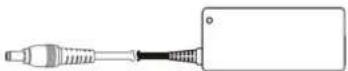
a. System
b. Utility and Driver bank
c. Power adapter (65W)
d. Power cord
e. RJ50-to DB9 cable (x1) (P/N: 50.WT201.0110)
Note:
The pictures may look slightly different from the product you purchased, due to our constant
product improvement effort.
1-2. Optional Accessories
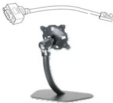
RJ-50 to DB9 cable
P/N: 50.WT201.0110
Desktop Stand
P/N:90.WT134.0010
Floor Stand
P/N:90.WT134.0010
natural_image
Illustration of a desktop microphone with attached cable and connector (no text or symbols)Desktop LCD Display / Stand
Configuration
Available for option
* This model is fitted with wheels and allows easy movement.
* LCD monitor can be adjustable the height from 1100mm jto 1700mm high.
* Main holder dimension: 1700(H) x 600(W) x 600(D) mm.
* With 75mm x 75mm & 100mm x 100mm VESA standard interface.
* Max loading: 10kgs.
* Material: Aluminum.
* Option second mounting KIT.

natural_image
Line drawing of a standard office stand with five legs and a blank rectangular panel (no text or symbols)Note:
Please set up monitor as landscape, for safety reason no allow turn it to portrait.
2. System View
2-1. Front View
natural_image
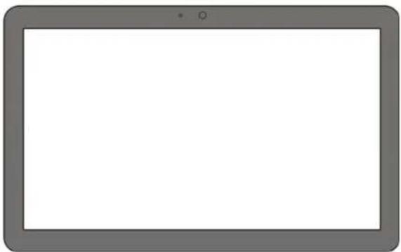
Front view of a gray tablet device with blank screen (no text or symbols)1 Touch screen
2 IR Receiver and LED indicate
2-2. Rear View

natural_image
Technical line drawing of a rectangular electronic panel with internal components and mounting holes (no text or symbols)3 Speaker holes
4 Hard drive disk door
5 VESA mounting screw holes
6 Ventilation holes
2-3. I/O Ports View
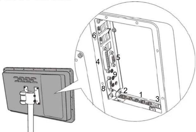
- RJ-50 RS232 x 4
- RJ-11 Cash Drawer Connector
- RJ-50 Monitor RS232 support Daisy Chain
- Printer Port
- PC VGA out
- Dual Giga LAN
- USB x 4
- Monitor VGA in
- Antenna Hole x3
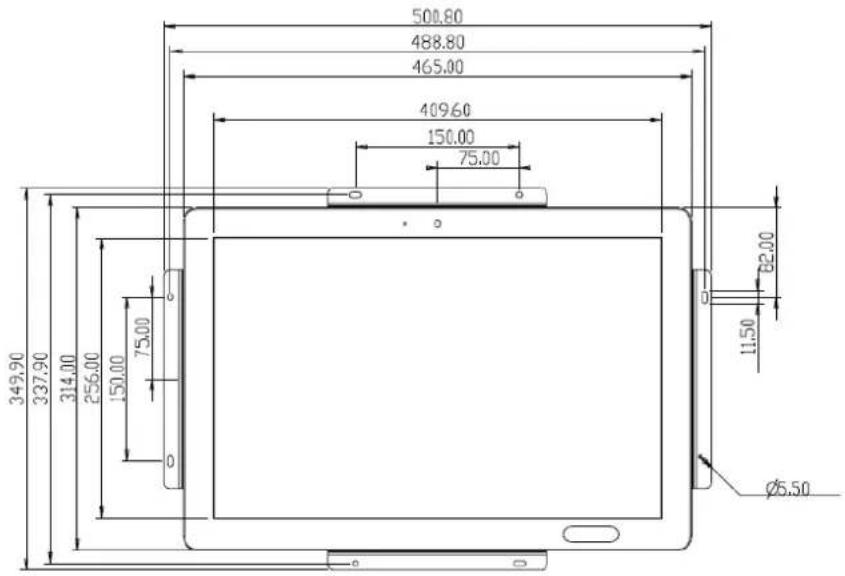
2-4. Dimensions
| Panel Size System Size | ||
| WT19M-RC 428.0(W) x 278.0(H) x 16.5(D) (Typ) 465x314x6 | 7.6mm (WxHxD) |
3. System Assembly
3-1. HDD Replacement
- Turn to the rear side of the system.


natural_image
Diagram of a device panel with a red arrow pointing to a component, no text or symbols present- Unscrew the screw (x1) securing the HDD door and the rear cover of the system.

natural_image
Technical line drawing of a computer monitor frame with two red circular annotations highlighting the mounting points (no text or symbols present)- Disconnect the SATA cable from the drive.

natural_image
Technical line drawing of a computer case with a red arrow pointing to the front panel (no text or symbols present)3-2. RAM Replacement
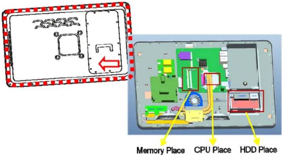
Opening the Rear Cover
Please open the rear cover first then remove and replace the RAM module.
You can refer to the motherboard layout to find the memory compartment.
- Remove the HDD (see Chapter 3-1) and unscrew the screws (x19) on the rear cover to access the motherboard.
Removing a RAM Module
- Use both fingers to pull the ejector clips out of the sides of the module.
- Slide the memory module out of the memory slot.

natural_image
3D diagram of a mechanical component with internal channels and directional arrows indicating movement (no text or symbols)Installing a RAM Module
- Slide the memory module into the memory slot and press down until the ejector clips click in
place.

natural_image
Diagram of a battery pack with internal compartments and mounting points (no text or symbols)3-4. Power Adapter Replacement
- Disconnect the power cable from the I/O panel.
4. Peripheral Installation
4-1. External Module Installation
- Turn the system to the rear side.
-
Attach the external module into the right position of the system and fasten the screws (x2).
-
Connect the external module cable to the USB and COM-RJ45 convertible connector on the I/O panel.
Note:
Please set up the power setting for COM3 or COM4 with 5V, see Chapter 6 - Jumper Setting

natural_image
Technical line drawing of a device casing with mounting brackets and internal compartments (no text or symbols)4-2. Wall Mount Kit Assembly
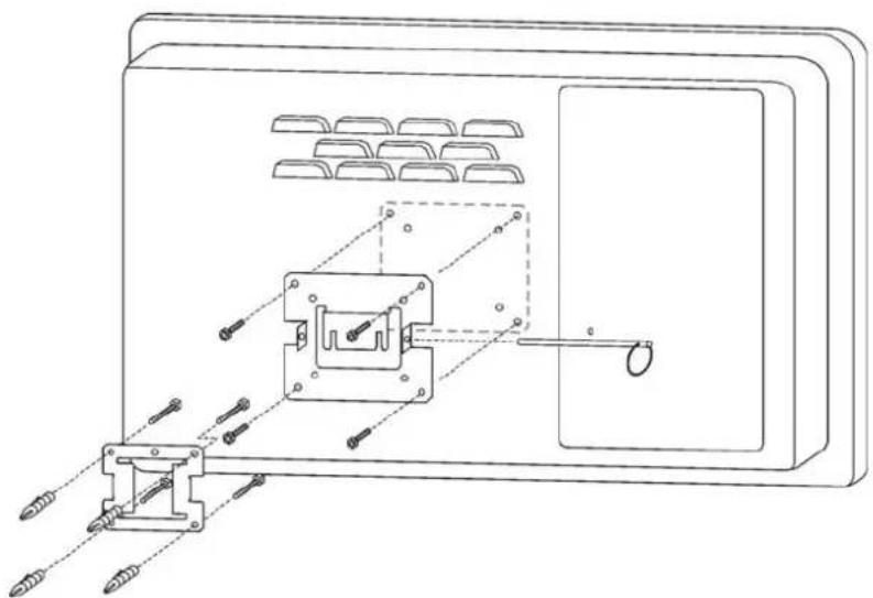
-
Fix the wall-mount bracket onto the wall.
-
Place the VESA bracket onto the VESA mounting holes on the system and fasten the screws (x4).
-
Align the VESA bracket with the system into the wall-mount brakcet and make sure they are well
natural_image
Technical line drawing of a mechanical assembly with mounting brackets and internal components (no text or symbols)4-4. Wireless LAN Installation
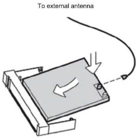
4-5. CF Card Module Installation
- Turn over the system to access the HDD door.
- Unfasten the screw (x1) to remove the HDD door.

natural_image
Diagram of a hand holding a cylindrical object with a bracket, next to a panel with ventilation grilles and a directional arrow (no text or symbols)- Assemble the CF to SATA bridge board onto the HDD bay with the screws (x3).

natural_image
Technical line drawing of a mechanical assembly with two views: top shows internal components, bottom shows a blank component with a downward arrow (no text or symbols)- Replace the CF card by sliding it into or outward from the slot of CF bridge board.
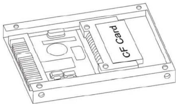
- Reverse the step 1 to cover the HDD door.
4-6. Cash Drawer (RJ-11) Software Configuration
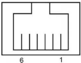
You can install a cash drawer through the cash drawer port. Please verify the pin assignment before installation.
Cash Drawer Pin Assignment
natural_image
Simple geometric diagram with a rectangle and vertical lines, labeled with numbers 6 and 1 at the bottom (no text or symbols within the diagram itself)| Pin | Signal |
| 1 | GND |
| 2 | DOUT |
| 3 | DIN |
| 4 12V / 19V | |
| 5 | DOUT |
| 6 | GND |
bit0
bit0
bit1
Cash Drawer Controller Register
The Cash Drawer Controller use one I/O addresses to control the Cash Drawer.
Attribute: Read / Write
Size: 8bit
| BIT | BIT7 | BIT6 | BIT5 | BIT4 | BIT3 | BIT2 | BIT1 | BIT0 |
| Attribute | Reserved | Read | Reserved | Write | ||||
Reserved

flowchart
graph TD
    A["Reserved"] --> B["Cash Drawer "DOUT bit1" pin output control"]
    B --> C["Cash Drawer "DOUT bit0" pin output control"]
    C --> D["Reserved"]
    D --> E["Cash Drawer "DIN bit0" pin input status"]
    E --> F["Reserved"]

COM Connector Pin 36 = SuperIO(F81865F) Pin 53 as GPIO01
COM Connector Pin 38 = SuperIO(F81865F) Pin 54 as GPIO02
COM Connector Pin 40 = SuperIO(F81865F) Pin 56 as GPIO04
How to program the related registers:
out 0x4e, 0x87 ; Enable register read/write by softere.
out 0x4e, 0x87
out 0x4e, 0x07
out 0x4f, 0x06 ; Set LDN
out 0x4e, 0x30 ; Set register's Index(0x30, for example)
in byte_value, 0x4f ; Get the register value from chip.
and byte_value, 0xfe ; Clear the related bits. ("Enable/Disable GPIO Port", for example)
or byte_value, 0x01 ; Set the related bits. ("Enable/Disable GPIO Port", for example)
out byte_value. 0x4f ; Set the register value into chip.
out 0x4e, 0xaa ; Disable register read/write by softere.
The register's in datasheet; you can reference to the attached file.
The session is "8.6 GPIO Registers(CR06)" in page 87.
You have to program the following registers in basic:
CR06 Index F0h[1] = 0/1 = GPIO01(COM Connector Pin 36) as input/output pin
CR06 Index F0h[2] = 0/1 = GPIO02(COM Connector Pin 38) as input/output pin
CR06 Index F0h[4] = 0/1 = GPIO04(COM Connector Pin 40) as input/output pin
CR06 Index F1h[1] = 0/1 = GPIO01(COM Connector Pin 36) with a Lo/Hi voltage output while it is output mode.
CR06 Index F1h[2] = 0/1 = GPIO02(COM Connector Pin 38) with a Lo/Hi voltage output while it is output mode.
CR06 Index F1h[4] = 0/1 = GPIO04(COM Connector Pin 40) with a Lo/Hi voltage output while it is output mode.
CR06 Index F2h[1] = 0/1 = GPIO01(COM Connector Pin 36) read as a Lo/Hi voltage input while it is input mode.
CR06 Index F2h[2] = 0/1 = GPIO02(COM Connector Pin 38) read as a Lo/Hi voltage input while it is input mode.
CR06 Index F2h[4] = 0/1 = GPIO04(COM Connector Pin 40) read as a Lo/Hi voltage input while it is input mode.
The following setting is by your add-board design:
CR06 Index F3h[1] = 0/1 = GPIO01(COM Connector Pin 36) with a open-drain/push-pull design.
CR06 Index F3h[2] = 0/1 = GPIO02(COM Connector Pin 38) with a open-drain/push-pull design.
CR06 Index F3h[4] = 0/1 = GPIO04(COM Connector Pin 40) with a open-drain/push-pull design.
In DOS, you just use ASM with "in" "out" command or C with "inportb" "outportb" or QBasic with "INP" "OUT".
If your program is in Windows, you have to write a Ring-0 I/O driver to access 0x4e/0x4f I/O ports.
Or, you can use the DLL written by some one:
IO.DLL - http://www.geekhideout.com/iodll.shtml
WinIO.DLL - http://www.internals.com/
How to write a C/C++/Basic or the other program: all description are on the OfficialWebSite and ZIP file, please reference it.
Cash Drawer Control Command Example
Use Debug.EXE program under DOS or Windows98
4-7. Gravity Vector Seneor's GPIO Pins Software Configuration

- Set PCH_GPIO6, PCH_GPIO7 as GPIO pins mode
in byte_value, 0x0501
and byte_value, 0x3f
or byte_value, 0xc0
out 0x0501, byte_value
- Set PCH_GPIO6, PCH_GPIO7 as Input pins mode
in byte_value, 0x0504
and byte_value, 0x3f
or byte_value, 0xc0
out 0x0504, byte_value
- Read PCH_GPIO6, PCH_GPIO7 status to know the gravity vector.
in byte_value, 0x050c
and byte_value, 0xc0
if (byte_value = 0x00) { gravity vector = ? and what to do. } //; Depends on install location
if (byte_value = 0x40) { gravity vector = ? and what to do. }
if (byte_value = 0x80) { gravity vector = ? and what to do. }
if (byte_value = 0xc0) { gravity vector = ? and what to do. }
In DOS, you just use ASM with "in" "out" command or C with "inportb" "outportb" or QBasic with "INP" "OUT".
If your program is in Windows, you have to write a Ring-0 I/O driver to access 0x4e/0x4f I/O ports.
Or, you can use the DLL written by some one:
IO.DLL - http://www.geekhideout.com/iodll.shtml
WinIO.DLL - http://www.internals.com/
How to write a C/C++/Basic or the other program: all description are on the OfficialWebSite and ZIP file,
please reference it.
5. Specification
CPU
Intel D2550 (1.86G Cedar Trail-D)
CHIPSET
Intel NM10
MEMORY
Support : SO-DIMM DDR3 x 2 (MAX 4G) Default 4G
GRAPHICS
Intel CPU Build-in
LAN
Dual LAN
Audio
Realtek ALC886
Mini-Card slot
x2 (Wi-Fi, Digital TV Tuner card, 3G Module for optional)
Storage
320G 2.5" SATA HDD
32G\~ 2.5" SATA SSD (Optional)
SYSTEM BIOS
AMI 8Mb SPI Flash ROM BIOS
Touch Panel
Win 7 support 10 Fingers (AMR Multi Touch)
Another SPEC
Standard VESA Screw Hole (100x100mm)
Build-in 2W Stereo Speaker and MIC
Build-in 1.3M (Crystal Eye) Camera
Watchdog Timer: (1sec \~255sec)
Wall Mount kit included
Panel 19" (1440x900 250cd/m²)
Bottom Side I/O – with cover
COM Port x4, Printer Port x1 (option)
USB 2.0 x6
GbE LAN RJ45 *2 (TBD)
5.1 CH Audio Jack (horizontal x 3)
DC 19V (AC Adaptor 19V/65W)
VGA input connector x1 from AD board
VGA output connector x1 from Motherboard (for Dual Display)
On Board Pin Head / Connector on board
Fan power x 2
USB 8Pin x 1
Monitor IR Receiver and Remoter Controller (Optional)
Dimension / Weight (reference only)
465x314x67.6mm(WxHxD) / 7.6Kg
6. Jumper Setting
6-1. For Huronriver Motherboard
6-1-1.Motherboard Placement

6-1-2. I/O board Placement

6-1-3. Jumper Setting
RJ50-DB9F serial Cable

Pin Definition
| RJ45 Pin RS_ | 232 RS_485 RS_ | 422 DB9 Pin | ||
| 2 | DCD# | RS485_TXRX- | RS422_TX- | |
| 4 | RX# | RS485_TXRX+ | RS422_TX+ | |
| 6 | TX# | NC | RS422_RX+ | |
| 8 | DTR# | NC | RS422_RX- | 4 |
| 9 | GND | GND | GND | 5 |
| 3 | DSR# | NC | NC | |
| 5 | RTS# | NC | NC | 7 |
| 7 | CTS# | NC | NC | 8 |
| 10 | RI# | NC | NC | 9 |
| 1 | --- | NC | NC | --- |
3
1
2
6

| Pin | Signal | Pin | Signal |
| 1 | Data Carrier Detect | 6 | Data Set Ready |
| 2 | Received Data | 7 | Request to Send |
| 3 | Transmitted Data | 8 | Clear to Send |
| 4 | Data Terminal Ready | 9 | Ring Indicator |
| 5 | Signal Ground |
COM2 RS232/485/422 Setting

Default Setting
| COM2 setting | ||||
| J1 J2 J3 J4 | ||||
| RS232 1-2 | 3-5 3-5 | 1-2 | ||
| 4-6 4-6 | 3-4 | |||
| 5-6 | ||||
| RS422 3-4 | 1-3 1-3 | N/A | ||
| 2-4 2-4 | N/A | |||
| N/A | ||||
| RS485 5-6 | 1-3 1-3 | N/A | ||
| 2-4 2-4 | N/A | |||
| N/A | ||||
COM1, COM2, COM3 & COM4 RI or Power Setting

Default Setting
| RI Power | |||||
| Jumper J5 | J6 J7 J8 | ||||
| Port | COM1 COM2 COM3 CO | ||||
| RI 1-2 | 1-2 1-2 1-2 | ||||
| 5V 3-4 | 3-4 3-4 3-4 | ||||
| 12V | 5-6 5-6 | 5-6 5-6 | |||
Cash Drawer Power Setting
| RJ11 Power | |
| J9 | |
| 12V 1-2 | |
| 19V 2-3 | |
CMOS Operation Mode
Appendix A: Drivers Installation
The shipping package includes a Driver CD in which you can find every individual driver and utility that enables you to install the drivers on the system.
Please insert the Driver CD into the drive and double click on the "index.htm" to select the models. You can refer to the drivers installation guide for each driver in the "Driver/Manual List".
Part No.: 49.00000.0000 Doc. No.: WT22M-RH-OL-1108A
- Disposal Instruction (US)
- 廃棄上の指示
- Instruction de Disposition (French)
- Disclaimer
- Safety Instructions
- FCC notice
- Notice: Shielded cables
- Notice: Peripheral devices
- Caution
- Operation conditions
- Notice: Canadian users
- Table of Contents
- Packing List
- 1-1. Standard Accessories
- Note:
- 1-2. Optional Accessories
- Desktop LCD Display / Stand
- Configuration
- Available for option
- System View
- 2-1. Front View
- 2-2. Rear View
- 2-4. Dimensions
- System Assembly
- 3-1. HDD Replacement
- 3-2. RAM Replacement
- Opening the Rear Cover
- Removing a RAM Module
- Installing a RAM Module
- 3-4. Power Adapter Replacement
- Peripheral Installation
- 4-1. External Module Installation
- 4-2. Wall Mount Kit Assembly
- 4-5. CF Card Module Installation
- 4-6. Cash Drawer (RJ-11) Software Configuration
- Cash Drawer Controller Register
- Cash Drawer Control Command Example
- 4-7. Gravity Vector Seneor's GPIO Pins Software Configuration
- Specification
- CPU
- CHIPSET
- MEMORY
- GRAPHICS
- LAN
- Audio
- Mini-Card slot
- Storage
- SYSTEM BIOS
- Touch Panel
- Another SPEC
- Bottom Side I/O – with cover
- On Board Pin Head / Connector on board
- Dimension / Weight (reference only)
- Jumper Setting
- 6-1. For Huronriver Motherboard
- 6-1-2. I/O board Placement
- 6-1-3. Jumper Setting
- COM2 RS232/485/422 Setting
- COM1, COM2, COM3 & COM4 RI or Power Setting
- Cash Drawer Power Setting
- Appendix A: Drivers Installation
Brand : AOPEN
Model : WT19M-RC
Category : Cash register