
NFCDII - CD rack SANUS - Free user manual and instructions
Find the device manual for free NFCDII SANUS in PDF.


| Product Type | CD Shelf |
| Brand | Sanus |
| Model | NFCDII |
| Capacity | 66 CDs |
| Dimensions (W x H x D) | 17.5 x 6.5 x 5.5 inches |
| Weight | 10.5 lbs |
| Material | Steel |
| Finish | Black powder coat |
| Mounting Type | Freestanding / Desktop |
| Number of Shelves | 1 |
| Dividers | Adjustable |
| Power Source | None |
| Cleaning Instructions | Wipe with a soft, dry cloth. Avoid abrasive cleaners. |
| Safety Warning | Do not overload; ensure stable placement to prevent tipping. |
| Warranty | 5 years |
| Repairability | No user-serviceable parts. Contact Sanus for support. |
Frequently Asked Questions - NFCDII SANUS
User questions about NFCDII SANUS
0 question about this device. Answer the ones you know or ask your own.
Ask a new question about this device
Download the instructions for your CD rack in PDF format for free! Find your manual NFCDII - SANUS and take your electronic device back in hand. On this page are published all the documents necessary for the use of your device. NFCDII by SANUS.
USER MANUAL NFCDII SANUS
Assembly Instructions for Model: NFCDII
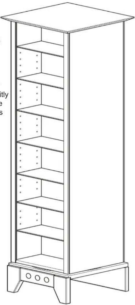
Thank you for choosing a Sanus Systems Natural Media Tower. The Model NFCDII is designed to keep your collection clean and organized by storing up to 430 CDs or 230 DVDs, all in one convenient location.
If you do not understand these directions, please contact Sanus at 800.359.5520 or www.sanus.com. Check carefully to make sure that there are no missing or defective parts. Our customer service representatives can quickly assist you with assembly questions, and missing or damaged parts. Replacement parts for products purchased through authorized dealers will be shipped directly to you. Never use defective parts. Improper assembly may cause damage or serious injury. Do not use this product for any purpose that is not explicitly specified by Sanus Systems. Sanus Systems can not be liable for damage or injury caused by incorrect assembly, or incorrect use. Please call Sanus Systems before returning products to the point of purchase.
Required Tools: Rubber mallet or hammer, phillips screwdriver, and an adjustable wrench.
Supplied Parts List: (Not to Scale)

natural_image
Line drawing of a multi-tiered storage cabinet with shelves and mounting feet (no text or symbols)Supplied Hardware: (Full Size)
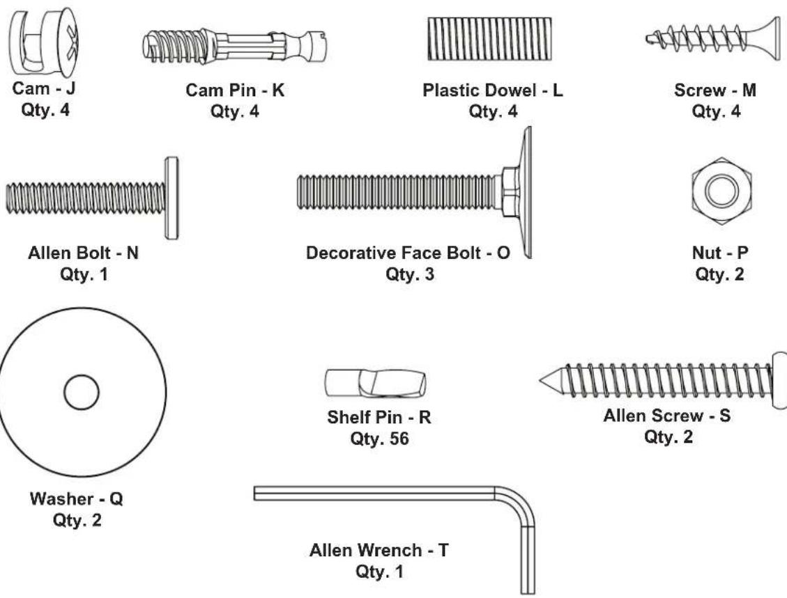
Step 1 - Insert Decorative Face Bolts into Front Leg
Insert the Decorative Face Bolts (O) into the Front Leg (D) making sure they are flush with the Front leg. If necessary, the rubber mallet may be used to lightly tap them into place.
Diagram 1

natural_image
Technical line drawing of a mechanical assembly with labeled components O and D (no text or symbols beyond labels)Step 2 - Secure Steel Tube to Front Leg
Lay the Front Leg (D) face down on a soft surface with the threads of the Decorative Face Bolts (O) facing up; then, place a Washer (Q) over the middle Decorative Face Bolt, and thread the Steel Tube (G) onto it. Firmly hand tighten the Steel Tube.
Diagram 2

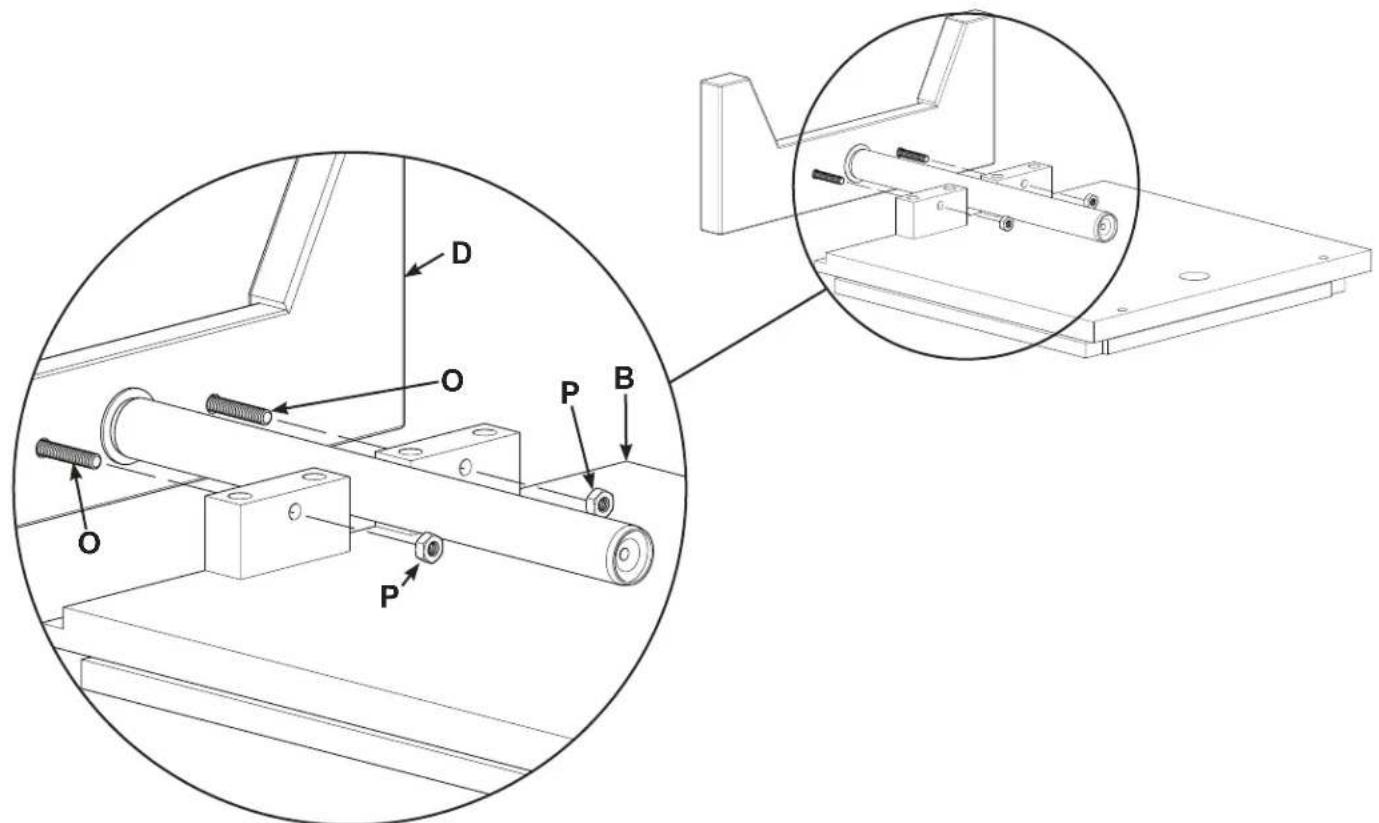
Step 3 - Secure Front Leg to NFCDII Base
Attach the Front Leg (D) to the NFCDII Base (B) by inserting the two outer Decorative Face Bolts (O) through the two holes of the NCFDII Base and securing with two Nuts (P). Use the adjustable wrench to firmly tighten the two Nuts.
Diagram 3
Step 4 - Secure Back Leg to Tube and NFCDII Base
Place a Washer (Q) between the Tube (G) and the Back Leg (C); then, using an Allen Bolt (N) secure the Back Leg to the Tube.
Using the two Allen Screws (S), secure the Back Leg (C) to the NFCDII Base (B).

Step 5 - Insert Cam Pins into Side Panels
There are two holes that are centered on each side of the Side Panels (F), and 12" [304.3 mm] from each end. Using the phillips screwdriver, screw Cam Pins (K) into the two holes of each Side Panel taking care not to over tighten the Cam Pins.

Step 6 - Insert Cam into Center Support.
Place a Cam (J) into each of the four holes in the Center Support (E).
NOTE: Each Cam has an arrow on it. Using a phillips screwdriver align each Cam so the arrow is pointing toward the small hole on the edge of the Center Support (See Detail - A).

flowchart
graph TD
    subgraph Diagram 6
        A1["Camera"] --> B1["Cam Hole"]
        A2["Camera"] --> B1
        B1 --> C1["Target Object"]
        C1 --> D1["Small Hole"]
        C1 --> E["Target Object"]
    end
    subgraph Detail_A
        F1["Camera - J"] --> G["Detail - A"]
        H1["Small Hole"] --> G
        G --> I["Target Object"]
    end
Step 7 - Secure Side Panels to Center Support.
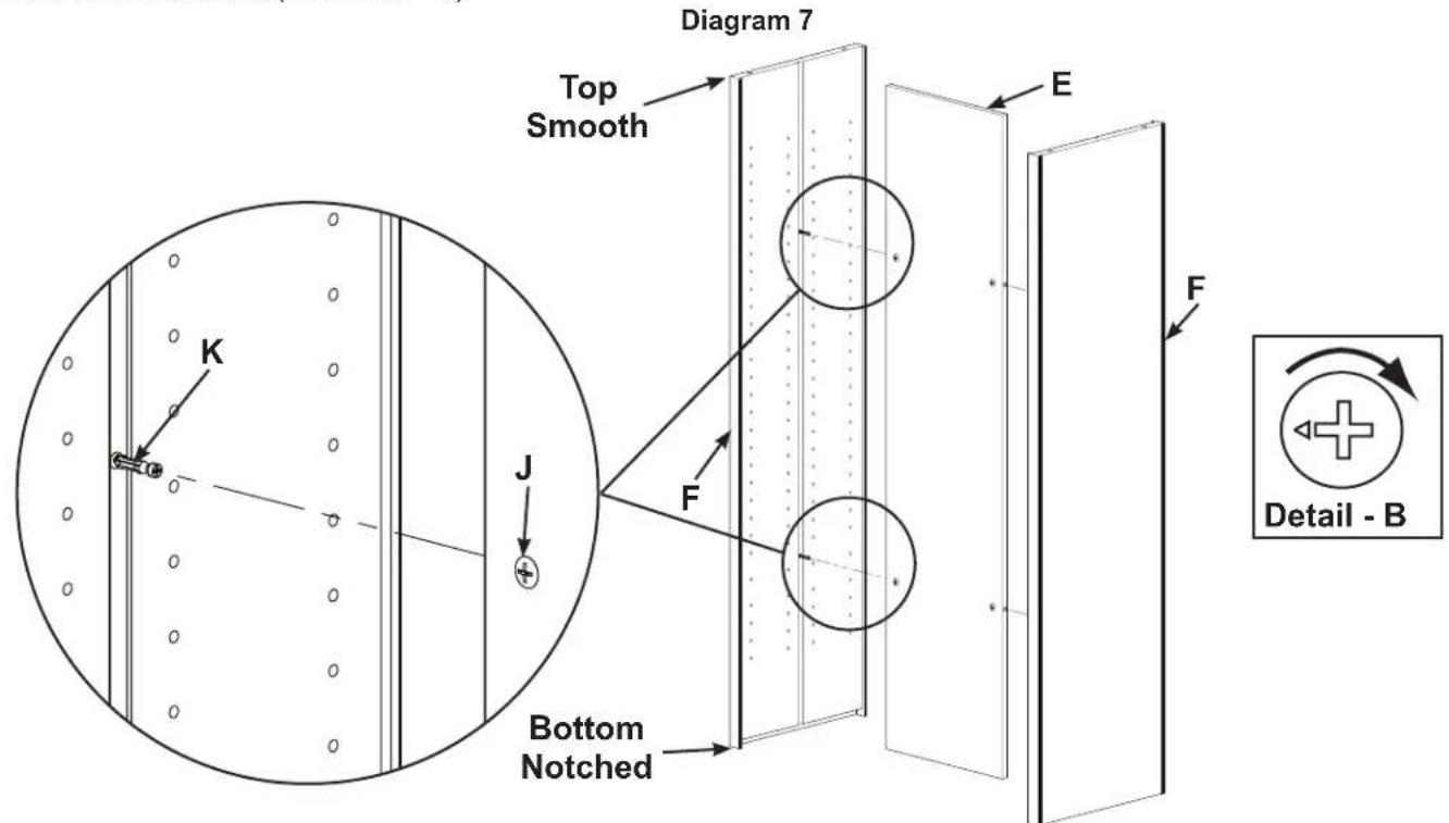
The Cam Pins (K) installed in each Side Panel (F) line up with the small holes in the edge of the Center Support (E). The top of each Side Panel is smooth and the bottom has a notch routed in the inside edge.
Attach a Side Panel to each side of the Center Support and using a phillips screwdriver, rotate each Cam (J) one-third turn clockwise until secure (See Detail - B).
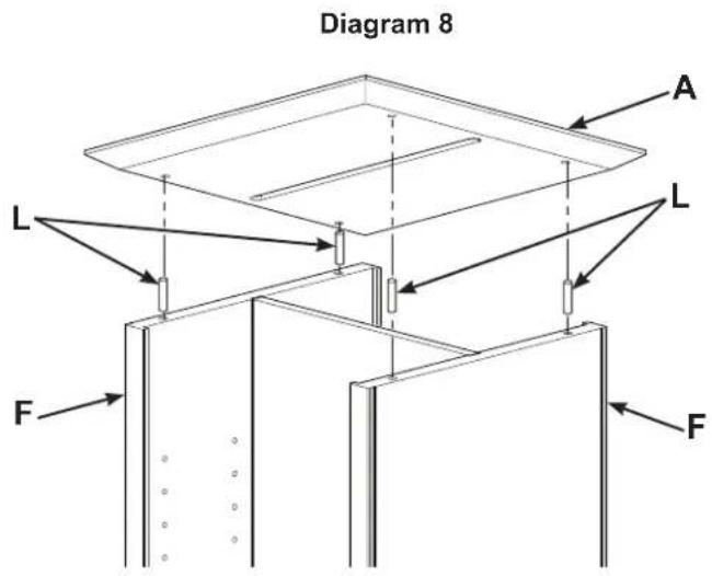
Step 8 - Attaching Top Panel
Stand the unit up so that the notched bottom of each Side Panel (F) is facing down and the smooth top edge is facing up.
Tap a Plastic Dowel Pin (L) into the holes in the top edge of each Side Panel (F); then, align the holes of the NFCDII Top Panel (A) with the Dowel Pins and the slot across the NFCDII Top with the Center support (E).
Firmly press the NFCDII Top onto the Dowel Pins and Side Panels, until it is firmly seated.
NOTE: Once the NFCDII Top is attached, it may not be removed without causing damage.
Step 9 - Attaching NFCDII Base Assembly
Turn the assembly over so that the Top (A) is resting on a towel or clean carpet. Gently fit the NFCDII Base (B) into the routed notches in each Side Panel (F). Rotate the NFCDII Base to expose the screw holes and secure with four Screws (M).

Step 10 - Installing Glass Shelves
Turn the assembly over. Place the Shelf Pins (R) in to holes in the Side Panels (F) where you want the Glass Shelves (H) to be located. Each Glass Shelf requires four shelf Pins.
Place the Glass Shelves (H) in the NFCDII Media Tower.
Diagram 10

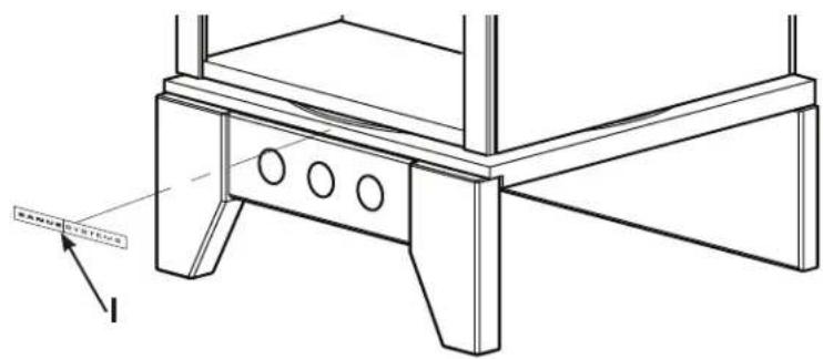
Step 11 - Attach Name Plate
Attach the Sanus Name Plate (I) to the desired location.
Diagram 11
- Assembly Instructions for Model: NFCDII
- Supplied Hardware: (Full Size)
- Step 1 - Insert Decorative Face Bolts into Front Leg
- Step 2 - Secure Steel Tube to Front Leg
- Step 3 - Secure Front Leg to NFCDII Base
- Step 4 - Secure Back Leg to Tube and NFCDII Base
- Step 5 - Insert Cam Pins into Side Panels
- Step 6 - Insert Cam into Center Support.
- Step 7 - Secure Side Panels to Center Support.
- Step 8 - Attaching Top Panel
- Step 9 - Attaching NFCDII Base Assembly
- Step 10 - Installing Glass Shelves
- Step 11 - Attach Name Plate
Brand : SANUS
Model : NFCDII
Category : CD rack