
JB3 - Boîte de jonction électrique Speco Technologies - Free user manual and instructions
Find the device manual for free JB3 Speco Technologies in PDF.


| Product Type | Outdoor Bullet Security Camera |
| Dimensions | 2.5 x 2.5 x 6.0 inches (approx.) |
| Weight | 0.5 lbs (approx.) |
| Power Supply | 12V DC, 500mA |
| Resolution | 1080p Full HD (1920x1080) |
| Night Vision | Up to 30 ft with IR LEDs |
| Lens Type | Fixed 3.6mm |
| Field of View | 80 degrees |
| Video Output | BNC (CVBS) or Ethernet (PoE optional) |
| Weatherproof Rating | IP66 |
| Mounting | Wall or ceiling mount bracket included |
| Operating Temperature | -40°F to 140°F (-40°C to 60°C) |
| Main Functions | 24/7 surveillance, motion detection, remote viewing |
| Cleaning and Maintenance | Wipe lens with microfiber cloth; check connections periodically |
| Safety Instructions | Use only specified power adapter; avoid exposure to extreme conditions beyond rating |
| Spare Parts and Reparability | Contact Speco support for replacement parts; unit is not user-serviceable |
| General Information | Compatible with most DVRs and NVRs; warranty 2 years |
Frequently Asked Questions - JB3 Speco Technologies
User questions about JB3 Speco Technologies
0 question about this device. Answer the ones you know or ask your own.
Ask a new question about this device
Download the instructions for your Boîte de jonction électrique in PDF format for free! Find your manual JB3 - Speco Technologies and take your electronic device back in hand. On this page are published all the documents necessary for the use of your device. JB3 by Speco Technologies.
USER MANUAL JB3 Speco Technologies
natural_image
Technical line drawing of a circular mechanical component with mounting holes and central hub (no text or symbols)Junction Box
Quick Star t Guide
Thank you for purchasing our products. All examples and pictures used in this manual are only for reference purpose. Please take the real object as the standard.
Before installation, make sure that the wall is strong enough to withstand 3 times the weight of the junction box and the camera. We only introduce the installation of some cameras with junction box in this manual.
● Mount the Junction Box and Bullet Camera
- Drill the screw holes on the wall according to the drill template.

natural_image
Pure technical diagram showing a circular component with cross symbol inside, supported by vertical lines and hatched background (no text or labels)- Push the expansion screws into the screw holes (if the wall is wooden, please skip this step) and then fix the mounting base of the junction box to the wall with screws.
- Reinstall the upper cover to the junction box.

natural_image
Technical line drawing of a mechanical assembly or mounting bracket (no text or symbols)- Open the mounting base and the upper cover of the junction box.

- Fix the mounting base of the camera to the upper cover of the junction box. Then route the cables through the cable hole (take side conduit cabling for example) and connect the cables.

natural_image
Technical line drawing of a mechanical assembly or lifting device (no text or symbols present)- Adjust the view angle of the camera.

natural_image
Technical line drawing of a mechanical assembly with a lever and base component (no text or symbols)● Mount the Junction Box and Dome Camera (1)
- Drill the screw holes on the wall according to the drill template.

natural_image
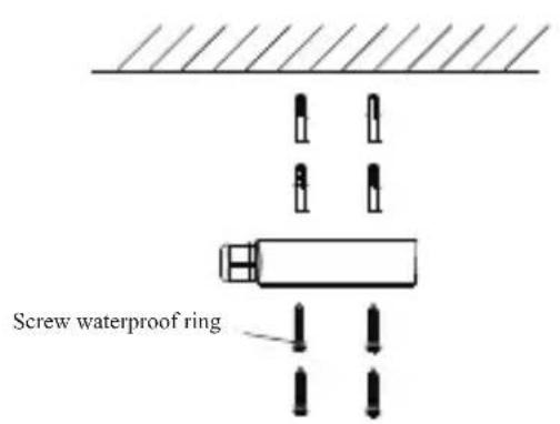
Pure electrical circuit lines without any symbols- Secure the mounting base of the junction box to the wall.
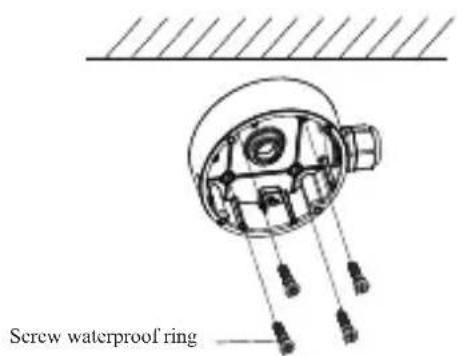
- Route the cables through the cable hole (take side conduit cabling for example) and connect the cables. Then reinstall the upper cover to the junction box.
natural_image
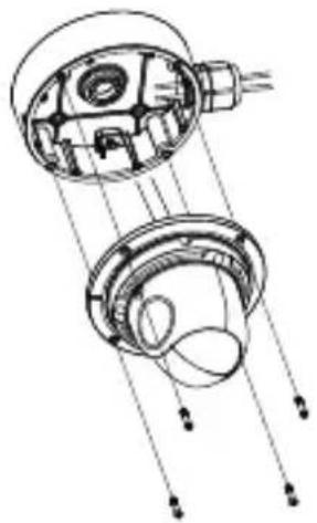
Technical line drawing of a mechanical assembly with internal components and alignment lines (no text or symbols)- Open the mounting base and the upper cover of the junction box.

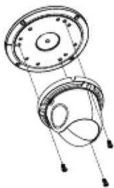
- Fix the camera to the upper cover of the junction box.
natural_image
Technical line drawing of two mechanical components with mounting holes and connecting rods (no text or symbols)- Adjust the view angle of the camera.
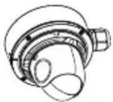
natural_image
Technical line drawing of a mechanical component with no visible text or symbols● Mount the Junction Box and Dome Camera (2)
The step 1 and step 2 are the same as the above-mentioned step 1 and step 2.
- Secure the mounting base of the junction box to the wall.

natural_image
Technical line drawing of a mechanical component with wires and housing (no text or symbols)- Unscrew the lock screw and then remove the mounting base of the camera.

- Connect the cables and then fix the lower dome to the mounting base by tightening the lock screw.

natural_image
Technical diagram of a mechanical assembly with two circular components and a shaft (no text or symbols)- Route the cables through the cable hole (take side conduit cabling for example). Then reinstall the upper cover to the junction box.

natural_image
Technical line drawing of a mechanical component with cross-sectional and top views (no text or symbols)- Mount the mounting base of the camera to the junction box.
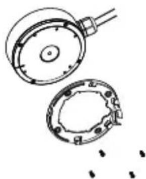
natural_image
Technical line drawing of a mechanical component with two views (top and side), no text or symbols present.- Remove the lower dome to adjust the view angle. After that, reinstall the lower dome to complete the installation.


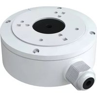
Brand : Speco Technologies
Model : JB3
Category : Boîte de jonction électrique