
HGT 765 XGH - Cooker HOOVER - Free user manual and instructions
Find the device manual for free HGT 765 XGH HOOVER in PDF.


| Product Type | Freestanding cooker (gas hob, electric oven) |
| Model | HGT 765 XGH |
| Brand | Hoover |
| Width | 60 cm (approximately) |
| Height | 85-90 cm (including control panel) |
| Depth | 60 cm (approximately) |
| Weight | Approximately 50 kg |
| Power Supply | 230 V, 50 Hz |
| Energy Class | A (typical for this range) |
| Hob Type | Gas burners (4 or 5, depending on configuration) |
| Oven Type | Electric multifunction oven |
| Oven Functions | Convection, grill, defrost, pizza, etc. |
| Oven Capacity | Approximately 65-70 liters |
| Cleaning | Catalytic liners (self-cleaning) |
| Safety Features | Flame failure device on gas burners, child lock, automatic shut-off |
| Spare Parts Available | Oven bulbs, heating elements, gas nozzles, etc. |
| Repairability | User replaceable oven bulb, simple parts accessible |
| Control Type | Knobs and digital timer |
| Installation | Freestanding, requires gas connection and electrical outlet |
Frequently Asked Questions - HGT 765 XGH HOOVER
User questions about HGT 765 XGH HOOVER
0 question about this device. Answer the ones you know or ask your own.
Ask a new question about this device
Download the instructions for your Cooker in PDF format for free! Find your manual HGT 765 XGH - HOOVER and take your electronic device back in hand. On this page are published all the documents necessary for the use of your device. HGT 765 XGH by HOOVER.
USER MANUAL HGT 765 XGH HOOVER
PIANI COTTURA AD INCASSO
MANUEL D'INSTRUCTIONS
PLANS DE CUISSON À ENCASTRER
HANDLEIDING
INBOUWKOOKPLATEN
GEBRAUCHSANLEITUNG
EINBAUKOCHMULDEN
INSTRUCTION BOOKLET
BUILT-IN COOKTOPS
MANUAL DE INSTRUÇÕES
PLACAS DE COZINHA DE ENCASTRE
INSTRUKCJA OBSŁUGI
PLYTY GAZOWE DO ZABUDOWY
HASZNALATI UTMUTATO
BEÉPÍTHETŐ ÜZHELYEK
ΒΙΒΛΙΟ ΟΔΗΓΙΩΝ
INSTRUCTIONS BOOKLET
built-in cooktops
Important warnings and tips for use
- IMPORTANT! This manual constitutes an integral part of the appliance. It must be kept intact and within easy reach during the entire life of the cooktop. Please carefully read this manual and all the instructions contained herein before using the appliance. Keep any spare parts supplied with the appliance. Installation must be carried out by a qualified technician and in compliance with current regulations. This appliance is intended solely for domestic use and is designed for the following functions: cooking and reheating food. Any other use is considered as improper.
The manufacturer declines all liability resulting from poor installation, tampering, inexpert use and use for purposes other than those specifically stated.
- Check that the appliance has not been damaged during transport.
- Keep all packaging materials (plastic bags, polystyrene foam, nylon, etc.) away from children, as they are potentially dangerous.
- Warning: in case of disassembly, maintenance and cleaning of the appliance, be careful, some parts could be sharp.
Please use suitable prevention and protection equipment
- The packaging material is recyclable, and marked with the recycling symbol

Dispose of the appliance responsibly.
- This appliance is not intended for use by persons (including children) with reduced physical, sensory or mental capabilities, or lack of experience and knowledge, unless they have been given supervision or instruction concerning use of the appliance by a person responsible for their safety.
- Children should be supervised to ensure that they do not play with the appliance.
- Installation and gas/electrical connections must be carried out by a qualified technician in accordance with the manufacturer's instructions and in full compliance with current laws and safety regulations.
- Electrical safety can only be guaranteed if the product is connected to a suitable earth connection.
- It is dangerous to modify or attempt to modify the appliance. In the event of a malfunction, do not attempt to repair the appliance yourself, but contact a qualified technician.
- After using the cooktop, ensure the indicator on the knob is turned to the "off" position and close the mains gas delivery tap or the gas cylinder tap.
- Should you decide not to use the appliance any longer, before scrapping it make it unusable in accordance with current environmental health and safety laws, ensuring any parts which might constitute a danger to children are rendered harmless.
- The appliance data plate, with technical specifications, is positioned at a visible point under the safety cover and is also enclosed with this manual. The data plate below the safety cover must under no circumstances be removed.
- Illustrations for the use of the appliance are grouped together at the end of this manual.
Declaration of Conformity
This appliance conforms to the following EC directives:
• 90/396/EEC "Gas safety requirements"
73/23/EEC "Low voltage" - Replace from 2006/95/EC and modifications
• 89/336/EEC "Electromagnetic compatibility" - Replaced from 2004/108/EC and modifications
• 89/109/EEC "Materials or objects destined to come into contact with foodstuffs"
• Regulation EC N°1935/2004 “Materials or objects destined to come into contact with foodstuffs”
These instructions are valid only for those countries whose ID initials appear on the data plate found on the instructions handbook and on the appliance
COOKTOP CHARACTERISTICS
Warnings:
This appliance is intended to be built-in on furniture.
• The installation class is type 3 for the gas part and type Y for the electric part.
• The furniture must be resistant to temperatures up to at least 90° C.
- For correct installation, see the relative section and the reference drawings.
- The use of a gas cooking appliance leads to the production of heat and humidity in the room in which it is installed. Make sure the kitchen is well -ventilated: keep the natural airing passages open or install a mechanical ventilation device (hood). Intensive and extended use of the appliance may require additional airing, such as opening a window, or more efficient ventilation, such as increasing the speed of the hood.
This handbook is intended for a single type of cooktop. The typeplate data shown on the back allows you to verify that it corresponds to your model.
The indications provided in the next sections, along with the figure located at the end of the manual (Fig 1), will help you become familiar with your appliance.
HOOVER
| Type: | P8S | W: 0.6230V~ 50Hz |
| Mod. Tc: | P8SUF5XKFV-U51G20 | |
| Code: | 33800699 | Pin: 1312BP4007 |
| Mod: | HGT 765 XGH |
COOKING POINTS
Mod: HGT 765 (Fig. 1)
- Left Triple-Crown 3,8 burner (TC)
- Middle rear Rapid burner (R)
- Middle front Auxiliary (A)
- Right rear Semi-Rapid burner (SR)
- Right front Semi -Rapid burner (SR)
USING THE COOKTOP
Gas burners
The inflow of gas to the burners is adjusted by the knobs in fig.4 that control the taps.
When the knob pointers coincide with the symbols shown below, the following settings are obtained:
Tap closed, no gas supply
Maximum flow, maximum gas supply
Minimum flow, minimum gas supply
Igniting the burners
This model is equipped with a safety valve which, if the burner goes out for any reason, automatically interrupts the supply of gas.
To restore operation, move the knob to position ● and repeat the igniting operations described in the next section.
Using burners with safety valves
Turn the knob of the gas tap to the maximum supply position, then press and hold down for about 4 - 5 seconds.
Release the knob and adjust the flame by turning the knob until reaching the desired intensity.
○Warning
The ignition device cannot be operated for more than 15.
If after this period the burner still has not lit, or if it has gone out for accidental reasons, wait at least 1 minute before repeating the operation.
Burner selection
The symbol printed above each knob on the control panel (drawing in fig.4) indicates t he correspondence between knob and burner. The selection of the most suitable burner depends on the diameter and capacity of the cookware (see table).
It is important that the pot diameter is suited to the power of the burner, in order to not compromise its high efficiency.
Pot / Pan diameter
| Burner | Minimum diameter | Maximum diameter |
| Auxiliary | 60 mm (with reducer) | 140 mm |
| Semirapid front | 160 mm 200 mm | |
| Semirapid rear | 160 mm 200 mm | |
| Rapid | 200 mm 240 mm | |
| Triple -crown | 240 mm 260 mm |
Adapting to different types of gas
If it is necessary to adapt the cooktop to gas different than that for which it is designed, the injectors will have to be replaced.
The spare injectors, if not provided with the cooktop, are available at the Service Centres.
The injectors to be replaced should be selected according to the injectors table.
The injectors are identified by their diameter, expressed in hundredths of mm and printed on the body of the injectors themselves.
Replacement of the injectors
Remove the grates and the flame spreader from the cooktop.
Use an open-end spanner to replace the injectors J (fig. 10) with the appropriate injectors for the gas to be used.
◆ Reassemble the burners.
No primary air regulation is necessary for the burners.
Adjustment of the minimum
After replacing the injectors, light the burner and take off the knob. Move the tap to the minimum position, insert a screwdriver in the rod and adjust as follows: screw in to decrease the flame, unscrew to increase the flame. (fig. 10)
For G30/G31 gas, screw the adjustment screw in completely.
In any case, the result should be a small flame which is uniform and regular along the entire crown of the burner.
Finally, check that the flame does not go out when the tap is turned quickly from maximum to minimum position. For burners with safety valves, check that the flame slightly licks the thermocouple. Verify the correct adjustment by leaving the burner on for a few minutes. If it goes out, increase the minimum.
Using the grates
The cooktop grates have been designed to make the use of the product convenient and safe.
We recommend that you check, before each use, the exact positioning and stability of the grate on the cooktop.
Furthermore, check that the rubber supports are always intact and arranged correctly.
Grate for small cookware (Fig. 2) - Optional
This is placed only over the grate of the auxiliary burner (the smallest one) when using cookware with a small diameter in order to prevent it from tipping over.
Special grate for WOKs (Fig. 3)
This is placed only over the grate of the triple crown burner when using a WOK (pan with concave bottom). To avoid causing serious anomalies in the burner operation, it is recommended that you do not use WOKs without this special grate and do not use the special grat e for flat-bottom cookware.
INSTALLATION INSTRUCTIONS
Important!
These instructions are intended for a qualified installer.
The appliance must be installed correctly and in compliance with current regulations.
Any work on the appliance must be done with the appliance disconnected from the electrical power supply.
INSTALLATION:
Installation is completely chargeable to the buyer. The Manufacturing Company is exempt from this service. Any operations requested from the Manufacturing Company as a result of incorrect installation are not covered by the guarantee.
If the cooktop is being installed on an oven base, all the necessary precautions must be taken to ensure installation in compliance with safety regulations (CEI - UNI - CIG). Pay particular attention that the electrical cable and gas supply pipe are positioned so as to not come in contact with the hot parts of the oven casing. Furthermore, if an oven without a cooling fan is installed under the cooktop, it is necessary to make openings in the built-in unit to ensure proper air circulation. These openings must guarantee a free surface of at least 300 cm2 distributed as shown in figure 8.
Installation in the top (surface of the furniture)
The cooktop can be installed on all furniture, as long as i t is heat resistant (withstanding temperatures up to at least 90°C).
The dimensions of the hole to make on the furniture surface and the minimum distances from the back and side walls and above the appliance are indicated in figures 5 and 6.
Consider that:
When the cooktop is installed without an oven beneath, it is mandatory to use a dividing panel between the bottom of the cooktop and the furniture underneath, at a minimum distance of 10 mm.
If the cooktop is matched with an oven, place a partition at a minimum distance of 15 mm, while maintaining ventilation as specified in fig. 8.
In any case the electrical connection of the two appliances must be realized separately, both for electrical reasons as well as to facilitate their extraction.
It is recommended that you use an oven with a forced cooling fan.
Fixing the cooktop
The cooktop must be fixed to the furniture as follows:
➢ Position the appropriate sealing gasket provided with the cooktop along the external perimeter of the hole made in the furniture according to the diagram in fig. 5, so that the ends of the strips are perfectly joined to one another without overlapping.
Arrange the cooktop in the hole on the furniture, making sure that it is centered.
Fix the cooktop to the furniture with the appropriate brackets supplied with the cooktop as illustrated in fig. 7.
Correct installation of the sealing gasket provides an absolute guarantee against the infiltration of liquids.
Installation room and discharge of combustion products
The appliance must be installed and operated in suitable rooms, and in any case in compliance with current laws.
The installer must refer to current laws regarding ventilation and evacuation of the combustion products.
In this regard, note that the air necessary for combustion is 2m3/h for each kW of power (gas) installed.
Installation room
The room where the gas appliance is installed must have a natural inflow of air necessary for combustion of the gas (standards UNI-CIG 7129 and 7131).
The inflow of air must come directly from one or more openings made on a free section of at least 100 cm2 (A, fig.9);
This opening must be built to ensure that it does not become obstructed either internally or externally, and it must be positioned near the floor, preferably on the side opposite the evacuation of combustion products.
When it is not possible to make the required openings, the necessary air may come from an adjacent room, ventilated as required, as long as this room is not a bedroom, a hazardous environment or under vacuum (UNI-CIG 7129).
Discharge of combustion products
Gas cooking appliances must discharge the combustion products through hoods connected directly to exhaust flues or directly outdoors (fig. 9).
If a hood cannot be installed, it is necessary to use an electric fan attached to an external wall or window in the room. This electric fan must have a suitable capacity to guarantee an air renewal of the kitchen at least 3-5 times its volume (UNI-CIG 7129).
Components illustrated in fig. 9
A: Opening for air intake
C: Hood for evacuation of combustion products
E: Electric fan for evacuation of combustion products
Connection to the gas system
Before installation, make sure the local distribution conditions (type and pressure of the gas) and the cooktop adjustments are compatible. To do this, check the data on the product typeplate attached to the cooktop and shown in this handbook.
The gas connection must be carried out in compliance with the standards UNI -CIG 7129 and 7131. The cooktop must be connected to the gas system using metal pipes or continuous -wall stainless steel hoses, in compliance with standard UNI -CIG 9891, with a maximum length of 2 m.
If metal hoses are being used, make sure that these do not touch any moving parts and are not crushed.
Perform the connection without producing any type of stress on the appliance.
The gas feed connector is a G1/2" threaded concentric reducer. (Fig.13)
For ISO R7 connections, the gasket is not necessary.
For ISO R228 connections, the head washer provided must be inserted.
When the connection operations are finished, check the seal of the connections using a soap solution.
Electrical connection
The appliance must be connected to the mains power supply after verifying that the voltage corresponds to the value indicated in the typeplate characteristics and that the sections of the electrical system cables can support the load indicated on the typeplate.
The plug that is used for the connection must be up to standard and suitable for the power absorbed by the appliance. If the appliance is to be connected directly to the mains, an omnipolar switch must be placed between the appliance and the mains which has a minimum opening distance of 3 mm between the contacts, is suitably sized for the load and satisfies the relative standards.
Do not use reducers, adapters or shunting switches for the connection to the mains, since these may overheat and cause burnouts.
The earthing of the appliance is mandatory. The manufacturer declines all responsibility resulting from failure to observe this rule. (Fig. 11)
If the power cord must be replaced, use a cable having the same characteristics as that provided, suitable for the load and temperature (type T90°C). This cable must be requested from the service centre. The end that goes to the appliance must also have the Yellow-Green earth wire 20 mm longer than the others. For the power cord dimensions, see the table below:
| Type of cooktop | Dimension |
| Only with gas burners | 3 X 0.75 mm2 H05 V2V2-F |
It is important connect the wire in accordance with the following colours/codes
BLUE
NEUTRAL (N)
BROWN
LIVE (L)
YELLOW-GREEN
EARTH

THE MANUFACTURER DECLINES ALL RESPONSIBILITY IF THE INSTRUCTIONS ABOVE AND RELEVANT SAFETY STANDARDS ARE NOT OBSERVED.
CLEANING
To keep your cooktop in good condition, it should be cleaned regularly after each use once it has cooled. Never remove the knobs from their seats.
Never use steam or high-pressure cleaners.
Enamelled parts
All enamelled parts must be washed only with a sponge and soapy water or using other non-abrasive products made specifically for enamelled surfaces. After washing, dry thoroughly.
Stainless steel surface
The stainless steel surface should be cleaned with a damp cloth and specific products easily found on the market. After rinsing well, if possible, dry with a buckskin cloth.
Grates
The enamelled grates of the cooktop have been designed to be washed even in the dishwasher.
The stainless steel reducer may take on a bluish colouring in the burner area due to the temperature. This effect may be attenuated using common stainless steel sponges available on the market.
Burners
The burners, composed of two pieces, can be removed and washed with suitable products. After cleaning, they must be thoroughly dried and replaced precisely on their seats.
With regard to the electric ignition, check that the electrode E (fig.12) is always clean.
Clean the probe T (fig.12) so as to allow regular operation of the safety valve. Both the electrode and the probe must be cleaned with caution. When finished, replace the burners precisely in their housing.
To prevent damage to the electric ignition, avoid using it when the burners are not in their seats.
MAINTENANCE
The appliances do not require particular maintenance, nevertheless it is recommended to have them checked at least once every two years. If the knobs become difficult to turn or the odour of gas is present, close the general tap and contact technical service.
The defective tap should be replaced together with the gasket.
CUSTOMER ASSISTANCE SERVICE
If you cannot identify the cause of the operating anomaly, switch off the appliance (do not subject it to rought treatment) and contact the Assistance Service.
PRODUCT SERIAL NUMBER. Where can i find it?
It is important you to inform the Assistance Service of your product code and its serial number (a 16 character code which begins with the number 3); this can be found on the guarantee certificate or on the data plate located on the appliance.
It will help to avoid wasted journeys to technicians, thereby (and most significantly) saving the corresponding callout charges.
| Category: | II 2H 3+ | Country: | IT GB PT ES GR CZ | |
| Tipo di gas/ Gas type / Gassoort / Gasart / Type de gaz / Túntoç aερίου / Tipo de gás / Gaz type | G20 | |||
| Pressione gas / Gas pressure / Pression gaz / Gasdruck / Presion gas / Πίεση του αερίου / Pressão gás / Tlak gasa / Tlak plina / Ciśnienie gazu / Gàz nyomása | 20 mbar | |||
| Bruciatori-burners-bruleursbrenner-quemodoresbranders-KoCapáciade-Queimadores-Plamenicibocas de gás-Gorilniki | Portata - power inputs - débit gascapacidad - vazão - debiet- vermogengaszufukravóτηταOpterećenje - Kapacitet - zmogljivostMax (kW) | Min (kW) | ∅ Iniettorinjecteur - inyectorinjectors - sproeiergasdüse - mlaznicabrizgalica - šobe | |
| A | 1,00 0,72 | 0,30 | ||
| SR | 1,75 | 0,44 | 0,97 | |
| R | 3,00 | 0,75 | 1,15 | |
| TC 3,8 | 3,80 1,50 1,35 | |||
| Tipo di gas/ Gas type / Gassoort / Gasart / Type de gaz / Túntoç aερίου / Tipo de gás / Gaz type / Vrsta gasa / Vrsta plina / Pritisk plina / Typ gazu / Rodzaj gazu | G30 G31 | |||
| Pressione gas / Gas pressure / Pression gaz / Gasdruck / Presion gas / Πίεση του αερίου / Pressão gás / Tlak gasa / Tlak plina / Ciśnienie gazu / Gàz nyomása | 28-30/37 mbar | |||
| Bruciatori-burners-bruleursbrenner-quemodoresbranders-KoCapáciade-Queimadores-Plamenicibocas de gás-Gorilniki | Portata - power inputs - débit gascapacidad - vazão - debiet- vermogengaszufukravóτηταOpterećenje - Kapacitet - zmogljivostMax (kw) | Min (kW) | ∅ Iniettorinjecteur - inyectorinjectors - sproeiergasdüse - mlaznicabrizgalica - šobe | |
| A | 1,00 0,37 0,50 | |||
| SR | 1,75 0,50 0,65 | |||
| R | 3,00 0,90 0,85 | |||
| TC 3,8 | 3,80 1,70 0,98 | |||
| Category: | II 2E+ 3+ | Country: | FR BE | |
| Tipo di gas/ Gas type / Gassoort / Gasart / Type de gaz | G20 / G25 | |||
| Pressione gas / Gas pressure / Pression gaz / Gasdruck / Presion gas | 20 / 25 mbar | |||
| Bruciatori-burners-bruleursbrenner-quemodoresbranders-KoCapáçidade -Queimadores-Plamenicibocas de gás-Gorilniki | Portata - power inputs - débit gascapacidad - vazão - debiet- vermogengaszufukravótnaOpterećenje - Kapacitet - zmogljivostMax (kW) | Min (kW) | ∅ Iniettorinjecteur - inyectorinjectors - sproeiergasdüse - mlaznicabrizgalica - šobe | |
| A | 1,00 0,30 0,72 | |||
| SR | 1,75 0,44 0,97 | |||
| R | 3,00 0,75 1,15 | |||
| TC 3,8 | 3,80 1,50 1,35 | |||
| Tipo di gas/ Gas type / Gassoort / Gasart / Type de gaz | G30 G31 | ||
| Pressione gas / Gas pressure / Pression gaz / Gasdruck / Presion gas | 28-30/37mbar | ||
| Bruciatori-burners-bruleurs | Portata - power inputs - débit gas | ∅ Iniettori | |
| brenner-quemodores | capacidad - vazão - debiet- vermogen | injecteur - inyector | |
| branders-KoCapáçidade -gaszufukravótna | injectors - sproeier | ||
| Queimadores-Plamenici | Opterećenje - Kapacitet - zmogljivost | gasdüse - mlaznica | |
| bocas de gás-Gorilniki | Max (kW) | Min (kW) | brizgalica - šobe |
| A | 1,00 0,37 0,50 | ||
| SR | 1,75 0,50 0,65 | ||
| R | 3,00 0,90 0,85 | ||
| TC 3,8 | 3,80 1,70 0,98 | ||
| Category: | II 2L 3B/P | Country: | NL | ||
| Tipo di gas/ Gas type / Gassoort / Gasart / Type de gaz | G25 | ||||
| Pressione gas / Gas pressure / Pression gaz / Gasdruck / Presion gas | 25 mbar | ||||
| Bruciatori-burners-bruleurs | Portata - power inputs - débit gas | ∅ Iniettori | |||
| brenner-quemodores | capacidad - vazão - debiet- vermogen | injecteur - inyector | |||
| branders-Kauotnpeç | IkaVótna - Capacidade - gaszufuhr | injectors - sproeier | |||
| Queimadores-Plamenici | Opterećenje - Kapacitet - zmogljivost | gasdüse - mlaznica | |||
| bocas de gás-Gorilniki | Max (kW) | Min (kW) | brizgalica - šobe | ||
| A | 1,00 | 0,30 | 0,72 | ||
| SR | 1,75 | 0,44 | 0,94 | ||
| R | 3,00 | 0,75 | 1,21 | ||
| TC 3,8 | 3,80 1,50 1,43 | ||||
| Tipo di gas/ Gas type / Gassoort / Gasart / Type de gaz | G30 G31 | ||||
| Pressione gas / Gas pressure / Pression gaz / Gasdruck / Presion gas | 28-30/37mbar | ||||
| Bruciatori-burners-bruleurs | Portata - power inputs - débit gas | ∅ Iniettori | |||
| brenner-quemodores | capacidad - vazão - debiet- vermogen | injecteur - inyector | |||
| branders-Kouotnpeç | gaszufuhravótna | injectors - sproeier | |||
| Queimadores-Plamenici | Opterećenje - Kapacitet - zmogljivost | gasdüse - mlaznica | |||
| bocas de gás-Gorilniki | Max (kW) | Min (kW) | brizgalica - šobe | ||
| A | 1,00 0,37 0,50 | ||||
| SR | 1,75 0,50 0,65 | ||||
| R | 3,00 0,90 0,85 | ||||
| TC 3,8 | 3,80 1,70 0,98 | ||||
| Category: | II 2ELL 3B/P | Country: | DE AT | ||
| Tipo di gas/ Gas type / Gassoort / Gasart / Type de gaz | G20 | ||||
| Pressione gas / Gas pressure / Pression gaz / Gasdruck / Presion gas | 20 mbar | ||||
| Bruciatori-burners-bruleursbrenner-quemodoresbranders-KoCapacidade-Queimadores-Plamenicibocas de gás-Gorilniki | Portata - power inputs - débit gascapacidad - vazão - debiet- vermogengaszufukavótnaOpterećenje - Kapacitet - zmogljivostMax (kW) | Min (kW) | ∅ Iniettorinjecteur - inyectorinjectors - sproeiergasdüse - mlaznicabrizgalica - šobe | ||
| A | 1,00 0,30 0,72 | ||||
| SR | 1,75 0,44 0,97 | ||||
| R | 3,00 | 0,75 | 1,15 | ||
| TC 3,8 | 3,80 1,50 1,35 | ||||
| Tipo di gas/ Gas type / Gassoort / Gasart / Type de gaz | G30/G31 | ||||
| Pressione gas / Gas pressure / Pression gaz / Gasdruck / Presion gas | 50/50 mbar | ||||
| Bruciatori-burners-bruleursbrenner-quemodoresbranders-KoCapacidade-Queimadores-Plamenicibocas de gás-Gorilniki | Portata - power inputs - débit gascapacidad - vazão - debiet- vermogengaszufukavótnaOpterećenje - Kapacitet - zmogljivostMax (kW) | Max (kW) | Min (kW) | ∅ Iniettorinjecteur - inyectorinjectors - sproeiergasdüse - mlaznicabrizgalica - šobe | |
| A | 1,00 | 0,37 | 0,43 | ||
| SR | 1,75 | 0,50 | 0,58 | ||
| R | 3,00 | 0,90 | 0,75 | ||
| TC 3,8 | 3,80 1,70 0,77 | ||||
| Tipo di gas/ Gas type / Gassoort / Gasart / Type de gaz | G25 | ||||
| Pressione gas / Gas pressure / Pression gaz / Gasdruck / Presion gas | 20 mbar | ||||
| Bruciatori-burners-bruleursbrenner-quemodoresbranders-KauotnpeçQueimadores-Plamenicibocas de gás-Gorilniki | Portata - power inputs - débit gascapacidad - vazão - debiet- vermogenIkaovótna - Capacidade - gaszufuhrOpterećenje - Kapacitet - zmogljivostMax (kW) | Min (kW) | ∅ Iniettorinjecteur - inyectorinjectors - sproeiergasdüse - mlaznicabrizgalica - šobe | ||
| A | 1,00 | 0,30 | 0,77 | ||
| SR | 1,75 | 0,44 | 1,00 | ||
| R | 3,00 | 0,75 | 1,34 | ||
| TC 3,8 | 3,80 1,50 1,52 | ||||
| Category: | II2ELwLs3B/P | Country: | PL | ||
| Rodzaj gazu / Type de gaz / Gassoort / Gasart | G20 | ||||
| Ciśnienie gazu / Pression gaz / Gasdruck | 20 mbar | ||||
| Palniki / bruleurs branders / brenner | Natężenie przepływu débit gas / vermogen / gaszufuhr | ∅ Dyszy / injecteur injector / gasdüse | |||
| Makx (kW) | Min (kW) | ||||
| A | 1,00 0,30 0,72 | ||||
| SR | 1,75 0,44 0,97 | ||||
| R | 3,00 0,75 1,15 | ||||
| TC 3,8 | 3,80 1,50 1,35 | ||||
| Rodzaj gazu / Type de gaz / Gassoort / Gasart | G30 | ||||
| Ciśnienie gazu / Pression gaz / Gasdruck | 36 mbar | ||||
| Palniki / bruleurs branders / brenner | Natężenie przepływu débit gas / vermogen / gaszufuhr | ∅ Dyszy / injecteur injector / gasdüse | |||
| Makx (kW) | Min (kW) | ||||
| A | 1,00 0,37 | 0,47 | |||
| SR | 1,75 0,50 | 0,62 | |||
| R | 3,00 0,90 | 0,80 | |||
| TC 3,8 | 3,80 1,50 | 0,93 | |||
| Rodzaj gazu / Type de gaz / Gassoort / Gasart | GZ35 | ||||
| Ciśnienie gazu / Pression gaz / Gasdruck | 13 mbar | ||||
| Palniki / bruleurs branders / brenner | Natężenie przepływu débit gas / vermogen / gaszufuhr | ∅ Dyszy / injecteur injector / gasdüse | |||
| Makx (kW) | Min (kW) | ||||
| A | 1,00 | 0,30 | 0,95 | ||
| SR | 1,75 0,44 | 1,21 | |||
| R | 3,00 | 0,75 | 1,58 | ||
| TC 3,8 | 3,80 1,50 1,95 | ||||
| Category: | II2HS 3B/P | Country: | HU | ||
| Gàz típusa | G20 | ||||
| Gàz nyomàsa | 25 mbar | ||||
| égöfeiek | gázellátás Max (kw) | gázellátás Min (kw) | ∅ Injektor | ||
| A | 1,00 0,30 0,68 | ||||
| SR | 1,75 0,44 0,91 | ||||
| R | 3,00 0,75 1,10 | ||||
| TC 3,8 | 3,50 1,50 1,28 | ||||
| Gàz típusa | G25.1 | ||||
| Gàz nyomàsa | 25 mbar | ||||
| égöfeiek | gázellátás Max (kw) | gázellátás Min (kw) | ∅ Injektor | ||
| A | 1,00 0,30 0,74 | ||||
| SR | 1,75 0,44 0,98 | ||||
| R | 3,00 0,75 1,25 | ||||
| TC 3,8 | 3,50 1,50 1,48 | ||||
Fig./Eik. 1
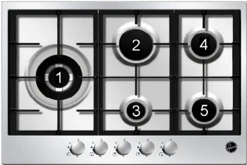
Fig./Eik. 2

Fig./Eik. 3

Fig./Eik. 4

Fig./Eik. 5

Fig./Eik. 6
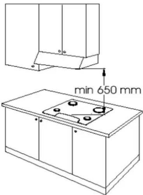
Fig./Eik. 7
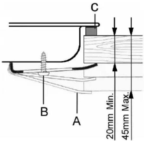
Fig./Eik. 8


Fig./Eik. 9

Fig./Eik. 10
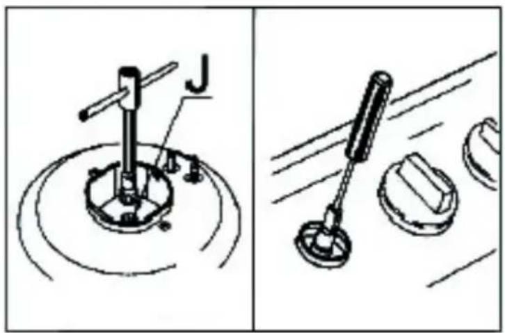
Fig./Eik. 11

Schema elettrico
Electrical wiring diagram
Schéma électrique
Schaltlan
Bedradingschema
Kapcsolási rajz
Schemat elektryczny
Fig./Eik. 13

IT A: Raccordo
B: Gasket
C: Pipe or hose
FR A: Raccord
B: Joint
C: Tuyau rigide ou flexible
PT A: Conexão
This appliance is marked according to the European directive 2002/96/EC on Waste Electrical and Electronic Equipment (WEEE).
By ensuring this product is disposed of correctly, you will help prevent potential negative consequences for the environment and human health, which could otherwise be caused by inappropriate waste handling of this product.

The symbol on the product, or on the documents accompanying the product, indicates that this appliance may not be treated as household waste. Instead it shall be handed over to the applicable collection point for the recycling of electrical and electronic equipment.
Disposal must be carried out in accordance with local environmental regulations for waste disposal.
For more detailed information about treatment, recovery and recycling of this product, please contact your local city office, your household waste disposal service or the shop where you purchased the product.
F
- MANUEL D'INSTRUCTIONS
- HANDLEIDING
- GEBRAUCHSANLEITUNG
- INSTRUCTION BOOKLET
- MANUAL DE INSTRUÇÕES
- INSTRUKCJA OBSŁUGI
- HASZNALATI UTMUTATO
- ΒΙΒΛΙΟ ΟΔΗΓΙΩΝ
- INSTRUCTIONS BOOKLET
- BUILT-IN COOKTOPS
- IMPORTANT WARNINGS AND TIPS FOR USE
- PLEASE USE SUITABLE PREVENTION AND PROTECTION EQUIPMENT
- DISPOSE OF THE APPLIANCE RESPONSIBLY
- DECLARATION OF CONFORMITY
- COOKTOP CHARACTERISTICS
- WARNINGS
- HOOVER
- COOKING POINTS
- USING THE COOKTOP
- GAS BURNERS
- IGNITING THE BURNERS
- USING BURNERS WITH SAFETY VALVES
- ○WARNING
- BURNER SELECTION
- ADAPTING TO DIFFERENT TYPES OF GAS
- REPLACEMENT OF THE INJECTORS
- ADJUSTMENT OF THE MINIMUM
- FOR G30/G31 GAS, SCREW THE ADJUSTMENT SCREW IN COMPLETELY
- USING THE GRATES
- GRATE FOR SMALL COOKWARE (FIG. 2) - OPTIONAL
- SPECIAL GRATE FOR WOKS (FIG. 3)
- INSTALLATION INSTRUCTIONS
- IMPORTANT
- INSTALLATION
- INSTALLATION IN THE TOP (SURFACE OF THE FURNITURE)
- CONSIDER THAT
- FIXING THE COOKTOP
- INSTALLATION ROOM AND DISCHARGE OF COMBUSTION PRODUCTS
- INSTALLATION ROOM
- DISCHARGE OF COMBUSTION PRODUCTS
- CONNECTION TO THE GAS SYSTEM
- ELECTRICAL CONNECTION
- CLEANING
- ENAMELLED PARTS
- STAINLESS STEEL SURFACE
- GRATES
- BURNERS
- MAINTENANCE
- CUSTOMER ASSISTANCE SERVICE
- PRODUCT SERIAL NUMBER. WHERE CAN I FIND IT
Brand : HOOVER
Model : HGT 765 XGH
Category : Cooker