
STP-131P - Label printer SAMSUNG - Free user manual and instructions
Find the device manual for free STP-131P SAMSUNG in PDF.


| Product Type | Thermal Label Printer |
| Model | Samsung STP-131P (Parallel Interface) |
| Printing Method | Thermal line printing |
| Dot Density | 180 x 180 dpi (7 dots/mm) |
| Printing Width | 72 mm |
| Paper Width | 80 mm |
| Characters per Line (Default) | 42 (Font A, 12x24) / 56 (Font B, 9x24) |
| Printing Speed | 23 lines/sec (75 mm/sec) |
| Receive Buffer Size | 15 KB |
| Power Supply Input | 100-240 VAC, 50/60 Hz |
| Power Supply Output | 24 VDC |
| Operating Temperature | 5°C to 40°C |
| Storage Temperature | -10°C to 50°C |
| Operating Humidity | 30% to 80% RH (non-condensing) |
| Storage Humidity | 10% to 90% RH |
| Paper Thickness | 0.062 mm to 0.075 mm |
| Maximum Roll Diameter | 83 mm |
| Roll Spool Diameter (Inside/Outside) | Inside: 12 mm / Outside: 18 mm |
| Print Head Life | 100 km (30,000,000 lines) |
| Auto Cutter Life | 1,000,000 cuts |
| Interface | Parallel (Centronics) |
| Peripheral Drive | Cash drawer kick-out (6-pin connector) |
| Character Scaling | Up to 64x original size |
| Barcode Printing | Yes (via barcode command) |
| Self-Test | Yes (hold FEED button while powering on) |
| Safety Certifications | FCC Class A, Canada Class A |
Frequently Asked Questions - STP-131P SAMSUNG
User questions about STP-131P SAMSUNG
0 question about this device. Answer the ones you know or ask your own.
Ask a new question about this device
Download the instructions for your Label printer in PDF format for free! Find your manual STP-131P - SAMSUNG and take your electronic device back in hand. On this page are published all the documents necessary for the use of your device. STP-131P by SAMSUNG.
USER MANUAL STP-131P SAMSUNG
Safety Precautions
When using this appliance, please observe the following safety regulations to prevent any hazard or material damage.

WARNING
Violating the following instructions can cause serious injury or death.
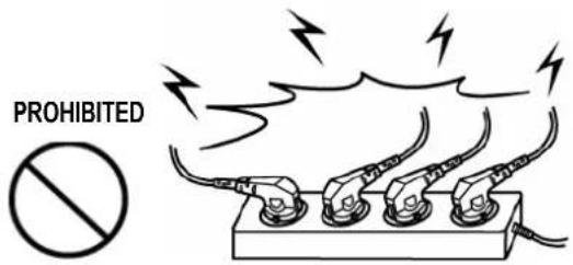
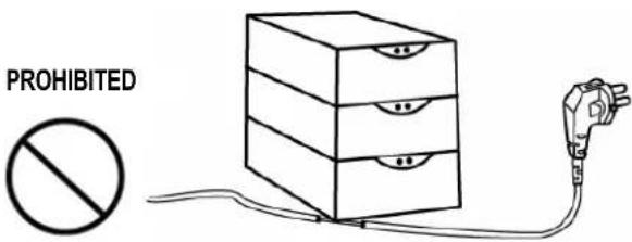
Do not plug several products into one multi-outlet.
• This can cause overheating and fire. - If the plug is wet or dirty, dry or wipe it before use. - If the plug does not fit perfectly into the outlet, do not plug it in. - Be sure to use only standardized multi-outlets.
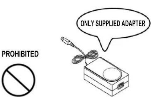
You must use only the supplied adapter.
- It is dangerous to use other adapters.
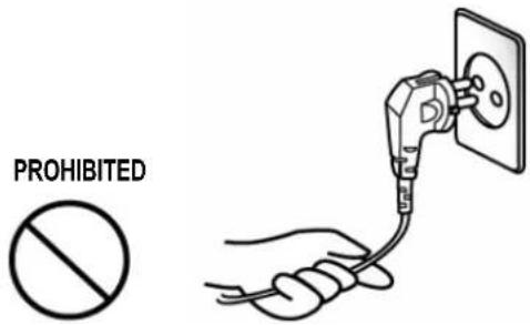
Do not pull the cable to unplug.
- This can damage the cable, which may cause a fire or breakdown of the printer.
Keep the plastic bag out of children's reach.
- If not, a child may put the bag over his head.

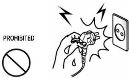
Do not plug in or unplug with wet hands.
- You can be electrocuted.
Do not bend the cable by force or leave it under any heavy object.
• A damaged cable can cause a fire.

CAUTION
Violating the following instructions can cause slight injury or damage to the appliance.
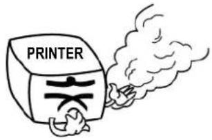
If you observe strange smoke, odor, or noise from the printer, unplug it before taking the following measures.
- Switch off the printer and unplug it from the mains. • After the smoke disappears, call your dealer to repair it.
TO UNPLUG
Keep the desiccant out of children's reach.
- If not, they may eat it.
PROHIBITED
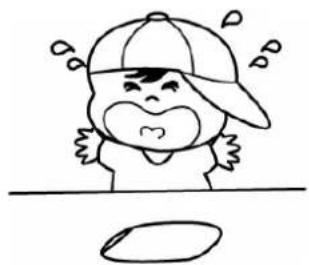
Install the printer on a stable surface.
- If the printer falls down, it can be broken and you can hurt yourself.
PROHIBITED

Use only approved accessories and do not try to disassemble, repair, or remodel it yourself.
- Call your dealer when you need these services.
- Do not touch the blade of the auto cutter.
DISASSEMBLING PROHIBITED

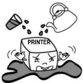
Do not let water or other foreign objects in the printer.
- If this happened, switch off and unplug the printer before calling your dealer.
PROHIBITED
Do not use the printer when it is out of order. This can cause a fire or an electrocution.
- Switch off and unplug the printer before calling your dealer.
TO UNPLUG

■ Warning - U.S.A
This equipment has been tested and found to comply with the limits for a Class A digital device, pursuant to Part 15 of the FCC Rules. These limits are designed to provide reasonable protection against harmful interference when the equipment is operated in a commercial environment. This equipment generates, uses, and can radiate radio frequency energy and, if not installed and used in accordance with the instruction manual, may cause harmful interference to radio communications. Operation of this equipment in a residential area is likely to cause harmful interference in which case the user will be required to correct the interference at his own expense.
This equipment has been tested and found to comply with the limits for a Class B digital device, pursuant to Part 15 of the FCC Rules. These limits are designed to provide reasonable protection against harmful interference in a residential installation. This equipment generates, uses and can radiate radio frequency energy and, if not installed and used in accordance with the instructions, may cause harmful interference to radio communications. However, there is no guarantee that interference will not occur in a particular installation. If this equipment does cause harmful interference to radio or television reception, which can be determined by turning the equipment off and on, the user is encouraged to try to correct the interference by one or more of the following measures:
- Reorient or relocate the receiving antenna.
- Increase the separation between the equipment and receiver.
- Connect the equipment into an outlet on a circuit different from that to which the receiver is connected.
- Consult the dealer or an experienced radio/TV technician for help.
■ Notice - Canada
This Apparatus complies with class "A" limits for radio interference as specified in the Canadian department of communications radio interference regulations.
■ Waste Electrical and Electric Equipment (WEEE)
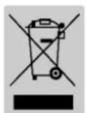
This marking shown on the product or its literature indicates that it should not be disposed of with other household wastes at the end of its working life. To prevent possible harm to the environment or human health from uncontrolled waste disposal, please separate this from other types of wastes and recycle it responsibly to promote the sustainable reuse of material resources. Household users should contact either the retailer where they purchased this product, or their local government office, for details of where and how they can take this item for environmentally safe recycling. Business users should contact their supplier and check the terms and conditions of the purchase contract. This product should not be mixed with other commercial wastes for disposal.
■ Label Material : PET
Caution
Some semiconductor devices are easily damaged by static electricity. You should turn the printer "OFF" before you connect or remove the cables on the rear side, in order to guard the printer against static electricity. If the printer is damaged by static electricity, you should turn the printer "OFF".
■ Introduction
The STP-131 Series Roll Printer is designed for use with electronic instruments such as system ECR, POS, banking equipment peripheral equipment, etc.
The main features of the printer are as follows:
- High speed printing: 23 lines per second.
- Low noise thermal printing.
- RS-232 (STP-131S Series), Parallel (STP-131P Series)
- The data buffer allows the unit to receive print data even during printing.
- Peripheral units drive circuit enables control of external devices such as cash drawer.
- Characters can be scaled up to 64 times compared to their original size.
- Bar code printing is possible by using a bar code command.
- Different print densities can be selected by DIP switches.
Please be sure to read the instructions in this manual carefully before using your new STP-131 Series.
NOTE
The socket-outlet shall be near the equipment and it shall be easily accessible.
All specifications are subject to change without notice.
Table of Contents
1. Setting Up the Printer....7
1-1 Unpacking....7 1-2 Functions 8 1-3 Adjustments and Settings 8
2. Connecting the Cables....9
2-1 Connecting the Power Supply 9 2-2 Connecting the Interface Cables ...... 10 2-2-1 STP-131S Serial Interface....11 2-2-2 STP-131P Parallel Interface 12
2-3 Connecting the Drawer.... 13
3. Setting the DIP Switches.... 14
4. Roll Paper Installation 15
5. Self Test.... 17
6. Hexadecimal Dumping ...... 18
7. Specification 19
1. Setting Up the Printer
1-1 Unpacking
Your printer box should include these items.
If any items are damaged or missing, please contact your dealer for assistance.
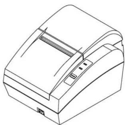
STP-131 Printer
Roll Paper Manual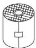
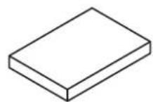
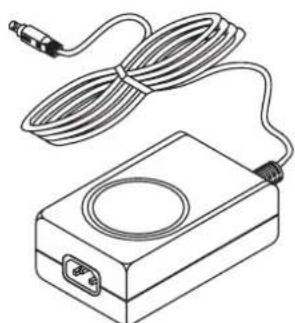
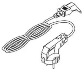
AC Adapter Power Cable
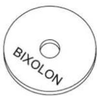
CD
※ Interface Cable (Option)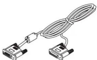
25 pin 25 pin 9 pin 25 pin
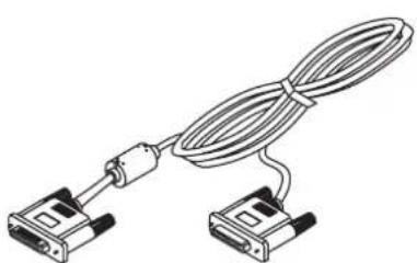
Parallel Cable Serial Cable
1-2 Functions
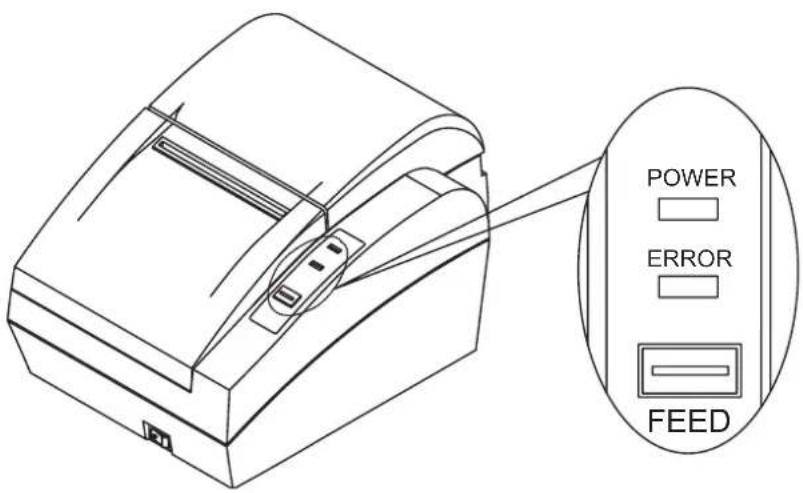
FEED Button
Press the FEED button once to advance paper one line.
You can also hold down the FEED button to feed paper continuously.
Indicator Lights
POWER (green)
The POWER light is on whenever the printer is on.
ERROR (red)
The error LED blinks fast when paper is out.
The error LED blinks when the Near End Sensor is triggered.
NOTE※
Both Power and Error LEDs are blank when the Printer Cover is open.
1-3 Adjustments and Settings
The STP-131 Series is set up at the factory to be appropriate for almost all users. It does, however, offer some settings for users with special requirements.
It has DIP switches that allow you to change communication settings, such as handshaking and parity check, as well as print density.
This STP-131 Series also has a near-end sensor for the paper. This can give you a warning when the paper is almost out. If you find that there is not enough paper remaining on the roll when the paper low is triggered, the Error LED (Red) is turned on.
2. Connecting the cables
Before connecting any of the cables, make sure that both the printer and the host are turned off.
2-1 Connecting the Power Supply
When connecting or disconnecting the power supply from the printer, make sure that the power supply is not plugged into an electrical outlet. Otherwise you may damage the power supply or the printer.
If the power supply's rated voltage and your outlet's voltage do not match, contact your dealer for assistance. Do not plug in the power cord. Otherwise, you may damage the power supply or the printer.
- Make sure that the printer's power switch is turned off, and the power supply's power cord is unplugged from the electrical outlet.
- Check the label on the power supply to make sure that the voltage required by the power supply matches that of your electrical outlet.
- Plug in the power supply's adapter cable as shown below. Notice that the flat side of the plug faces down.
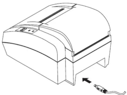
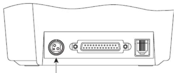
Power Connector Adapter Cable
To remove the DC cable connector, grasp the connector at the arrow and pull it straight out. Make sure that the main unit's power cord is unplugged before you disconnect the DC cable connector.
2-2 Connecting the Interface Cables
You need an appropriate interface cable.

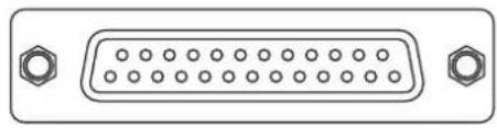
Interface Connector (Serial or Parallel)
- Plug the cable connector securely into the printer's interface connector.
- Tighten the screws on both sides of the cable connector.
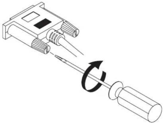
Attach the other end of the cable to the computer.
2-2-1 STP-131S Serial Interface
| Pin No. | Signal name | Direction | Function | |
| FG. | - | FrameDataReceive | ||
| 20 | TxD | Output | Transmit | |
| 19 | RxD | Input | ||
| 21 | CTS | Input Clear To | Send | |
| 22 | SG | - | Signal Ground | |
| 18 | RTS | Output | Request To Send |
| PRINTER | |
| 20 | TXD(O) |
| 19 | RXD(I) |
| 18 | RTS(O) |
| 21 | CTS(I) |
| 22~25 | FG,SG (GND) |
| CONNECT |
2-3 Connecting the Drawer


Drawer Kick-out Connector
WARNING
Use a drawer that matches the printer specification. Using an improper drawer may damage the drawer as well as the printer.
CAUTION
Do not connect a telephone line to the drawer kick-out connector; otherwise the printer and the telephone line may be damaged. Plug the drawer cable into the drawer kick-out connector on the back of the printer next to the power supply connector.
| Pin No. | Signal name | Direction | |
| 1 | Frame | ground | |
| 2 | Drawer kick-out drive signal 1 | Output | |
| 3 | Drawer open/close signal | Input | |
| 4 | +24V | ||
| 5 | Drawer kick-out drive signal 2 | Output | |
| 6 | Signal | ground | |
3. Setting the Dip Switches
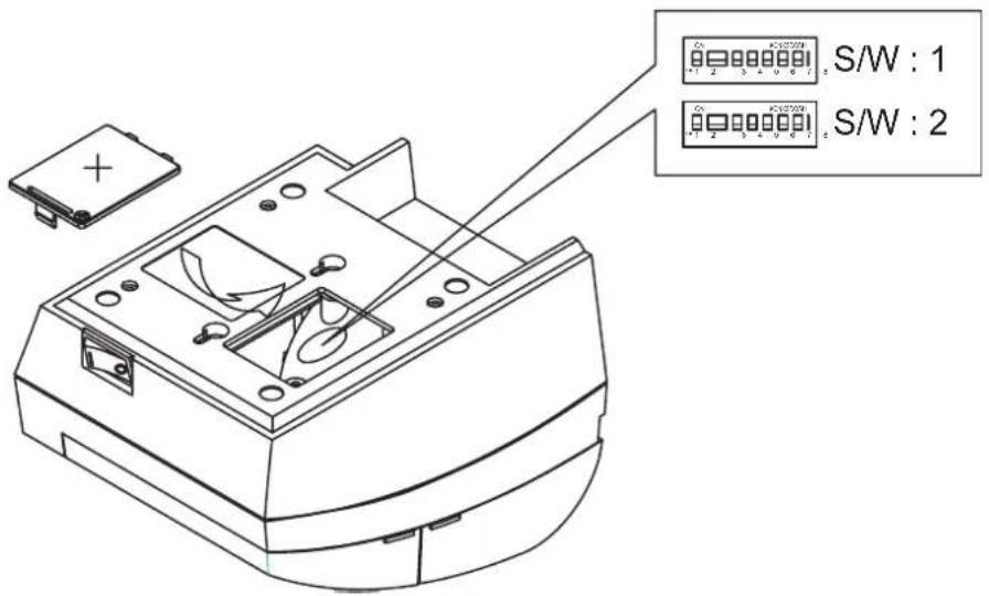
| No. | Dip Switch 1 | ||||
| Level BPS | S/W1 S/W2 | S/w3 | |||
| 1 | 2400 | ON | OFF | OFF | |
| 2 | 4800 | OFF | ON | OFF | |
| 3 | 9600 | OFF | OFF | ON | |
| 4 | 19200 | ON | OFF | ON | |
| 3 | 5 | 38400 | ON | ON | OFF |
| 6 | 57600 | OFF | ON | ON | |
| 7 | 115200 | ON | ON | ON | |
| Function | ON | OFF | |||
| 4 | Density | Dark | Normal | ||
| 5 | Handshaking | Xon/Xoff | DTR/DSR | ||
| 6 | Auto Feeding | With cutting | Without cutting | ||
| 7 | - | ||||
| 8 | Not used. Fixed to On | ||||
| No. | Dip Switch 2 | |||
| Function | ON | OFF | ||
| 1 | Auto cut | Full Cut | Partial Cut | |
| Parity | None Parity | Even Parity | Odd Parity | |
| 2 | OFF | ON | ON | |
| 3 | OFF | OFF | ON | |
| 4 | Not used. Fixed to OFF | |||
| 5 | Not used. Fixed to OFF | |||
| 6 | Not used. Fixed to OFF | |||
| 7 | Not used. Fixed to OFF | |||
| 8 | Not used. Fixed to OFF | |||
4. Roll Paper Installation
NOTE
Be sure to use paper rolls that meet specifications. Do not use paper rolls that have the paper glued to the core because the printer cannot detect the paper end correctly.
4-1 Make sure that the printer is not receiving data; otherwise, data may be lost.
4-2 Open the paper roll cover by pulling it up. You must turn on the printer before replacing the paper roll.
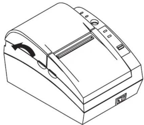
NOTE※
Do not open the print cover while the printer is operating. This may damage the printer.
4-3 Remove the used paper roll core if there is one.
4-4 Insert the paper roll.

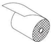
4-5 Be sure to note the correct direction that the paper comes off the roll.
O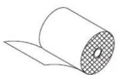
×
4-6 Close the cover.
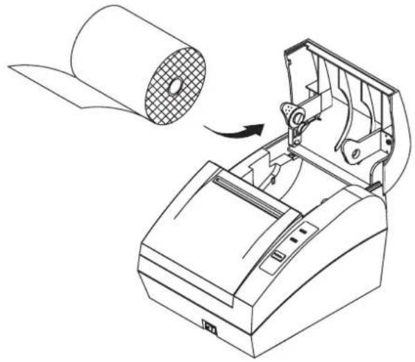
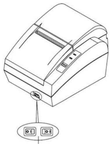
NOTE※
When closing the cover, press the center of the printer cover firmly to prevent paper mis-loading.
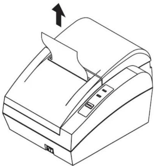
4-7 Tear off the paper as shown.
5. Self Test
The self-test checks whether the printer has any problems. If the printer does not function properly, contact your dealer. The self-test checks the following:
5-1 Make sure the paper roll has been installed properly. 5-2 Turn on the power while holding down the FEED button. The self-test begins. 5-3 The self-test prints the current printer status, which provides the control ROM version and the DIP switch settings. 5-4 After printing the current printer status, self-test printing will print the following, and pause.
SELF-TEST PRINTING. PLEASE PRESS THE FEED BUTTON.
5-5 Press the FEED button to continue printing. The printer prints a pattern using the built-in character set.
5-6 The self-test automatically ends and cuts the paper after printing the following.
*** COMPLETED ***
5-7 The printer is ready to receive data as soon as it completes the self-test.
6. Hexadecimal Dumping
This feature allows experienced users to see exactly what data is coming to the printer. This can be useful in finding software problems. When you turn on the hexadecimal dump function, the printer prints all commands and data in hexadecimal format along with a guide section to help you find specific commands.
To use the hexadecimal dump function, follow these steps:
6-1 Set DIP Switch 2 (sw-7 = Hex dump mode) of your printer to the ON position.
6-2 Turn on the power of your printer.
6-3 Run any software program that sends data to the printer. The printer will print all the codes it receives in a two-column format. The first column contains the hexadecimal codes and the second column gives the ASCII characters that correspond to the codes.
| 1B 21 00 1B 26 02 40 40 40 | 40 | . ! . . & . @ @ @ @ |
| 02 0D 1B 44 0A 14 1E 28 28 | 28 | . . . D . . . . ( ( ( |
| 00 01 0A 41 0D 42 0A 43 43 | 43 | . . . A . B . C C C |
- A period (.) is printed for each code that has no ASCII equivalent.
- During the hex dump, all commands except DEL EOT are disabled.
6-4 Close the cover, then the printer enters the hexadecimal dump mode.
6-5 Set DIP Switch 2 (sw-7 = Hex dump mode) of your printer to the off position and then hexadecimal mode is off.
- Specification
| Printing method Thermal line printing | ||
| Dot density 180 X 180 dpi (7dots/mm) | ||
| Printing width 72 mm | ||
| Paper width 80 mm | ||
| Characters per line (default) | 42 (Font A) (12 x 24)56 (Font B) (9 x 24) | |
| Printing speed | 23 lines/sec75 mm/sec | |
| Receive Buffer Size 15K Bytes | ||
| ※ NOTEPrinting speed may be slower, depending on the data transmission speed and the combination of control commands. | ||
| Supply voltage | SMPS Input voltage 100~240 VAC | |
| Frequency | 50/60 Hz | |
| SMPS Output voltage 24 VDC | ||
| Environmental conditions | Temperature | 5 ~ 40°C (Operating)-10 ~ 50°C (Storage) |
| Humidity | 30~80%RH (Operating)10 ~ 90 % RH (Storage); Except for paper | |
| LIFE* | MechanismHead | 30,000,000 lines100 Km |
| Auto Cutter 1,000,000 Cuts | ||
| Paper | Paper thickness: 0.062 ~ 0.075mm | |
| Roll size::∅83 mm | ||
| Roll spool diameter- Inside: ∅12mm (0.47")- Outside: ∅18mm (0.71") | ||


- SAFETY PRECAUTIONS
- WARNING
- DO NOT PLUG SEVERAL PRODUCTS INTO ONE MULTI-OUTLET
- YOU MUST USE ONLY THE SUPPLIED ADAPTER
- DO NOT PULL THE CABLE TO UNPLUG
- KEEP THE PLASTIC BAG OUT OF CHILDREN'S REACH
- DO NOT PLUG IN OR UNPLUG WITH WET HANDS
- DO NOT BEND THE CABLE BY FORCE OR LEAVE IT UNDER ANY HEAVY OBJECT
- CAUTION
- WARNING - U.S.A
- NOTICE - CANADA
- WASTE ELECTRICAL AND ELECTRIC EQUIPMENT (WEEE)
- LABEL MATERIAL : PET
- INTRODUCTION
- NOTE
- TABLE OF CONTENTS
- SETTING UP THE PRINTER
- CONNECTING THE CABLES
- SETTING THE DIP SWITCHES
- ROLL PAPER INSTALLATION
- SELF TEST
- HEXADECIMAL DUMPING
- SPECIFICATION
- UNPACKING
- FUNCTIONS
- FEED BUTTON
- INDICATOR LIGHTS
- POWER (GREEN)
- ERROR (RED)
- NOTE※
- ADJUSTMENTS AND SETTINGS
- CONNECTING THE POWER SUPPLY
- CONNECTING THE INTERFACE CABLES
- STP-131S SERIAL INTERFACE
- CONNECTING THE DRAWER
- SELF-TEST PRINTING. PLEASE PRESS THE FEED BUTTON
- COMPLETED
Brand : SAMSUNG
Model : STP-131P
Category : Label printer