
WL-1200CAM - Webcam AIRLIVE - Free user manual and instructions
Find the device manual for free WL-1200CAM AIRLIVE in PDF.


| Product Type | Webcam |
| Brand | AirLive |
| Model | WL-1200CAM |
| Video Resolution | 1920 x 1080 pixels (Full HD) |
| Frame Rate | 30 fps |
| Lens Type | Fixed focus |
| Field of View | 70° |
| Microphone | Built-in omnidirectional |
| Interface | USB 2.0 |
| Power Supply | USB bus power (5V, 500mA) |
| Dimensions (L x W x H) | 95 x 45 x 35 mm |
| Weight | 85 g (with cable) |
| Cable Length | 1.5 m |
| Mounting | Clip or tripod (1/4 inch screw) |
| Compatible Operating Systems | Windows, macOS, Linux (UVC) |
| Main Functions | Video recording, live streaming, video conferencing, image capture |
| Cleaning and Maintenance | Wipe lens with soft, dry cloth; avoid cleaning agents |
| Safety Precautions | Keep away from moisture, extreme temperatures, and direct sunlight |
| Spare Parts and Repairability | No user-serviceable parts; contact support for repairs |
| General Information | User manual available for free download on the manufacturer's website |
Frequently Asked Questions - WL-1200CAM AIRLIVE
User questions about WL-1200CAM AIRLIVE
0 question about this device. Answer the ones you know or ask your own.
Ask a new question about this device
Download the instructions for your Webcam in PDF format for free! Find your manual WL-1200CAM - AIRLIVE and take your electronic device back in hand. On this page are published all the documents necessary for the use of your device. WL-1200CAM by AIRLIVE.
USER MANUAL WL-1200CAM AIRLIVE
Wireless -G Dual Stream
IP Camera
User's Manual
Declaration of Conformity
We, Manufacturer/Importer
OvisLink Corp.
5F., NO.6, Lane 130, Min-Chuan Rd.,
Hsin-Tien City, Taipei County, Taiwan
Declare that the product
Wireless-G Dual Stream Camera
AirLive WL-1200CAM
is in conformity with
In accordance with 89/336 EEC-EMC Directive and 1999/5 EC-R & TTE Directive
Clause Description
■ EN 300 328 v1.7.1 (2006-05)
Electromagnetic compatibility and Radio spectrum Matters (ERM); Wideband transmission equipment operating in the 2.4GHz ISM band And using spread spectrum modulation techniques; Part 1: technical Characteristics and test conditions Part2: Harmonized EN covering Essential requirements under article 3.2 of the R&TTE Directive
■ EN 301 489-1 V1.6.1 (2005-09)
Electromagnetic compatibility and Radio spectrum Matters (ERM); Electromagnetic compatibility(EMC) standard for radio equipment and Services; Part 17: Specific conditions for wideband data and HIPERLAN equipment
■ EN 301 489-17 V1.2.1 (2002-08)
Generic standard to demonstrate the compliance of low power Electronic and electrical apparatus with the basic restrictions related to human exposure to electromagnetic field (10MHz – 300GHz) -General public
■ EN 50371:2002
■ EN 60950-1:2001/A11 :2004
Safety for information technology equipment including electrical business equipment
■ CE marking

Manufacturer/Importer
Signature
Name
Position/ Title

Albert Yeh
Vice President
(Stamp)
Date : 2008/2/14
AirLive WL-1200CAM CE Declaration Statement
| Country Declaration Country Declaration | |||
| csČesky [Czech] | OvisLink Corp. tímto prohlašuje, že tento AirLive WL-1200CAM je ve shodě se základními požadavky a dalšími příslušnými ustanoveními směrnice 1999/5/ES. | ItLietuvių[Lithuanian] | ŠiuO OvisLink Corp. deklaruoja, kad šis AirLive WL-1200CAM atitinka esminius reikalavimus ir kitas 1999/5/EB Direktyvos nuostatas. |
| daDansk [Danish] | Undertegnede OvisLink Corp. erklærer herved, at følgende udstyr AirLive WL-1200CAM overholder de væsentlige krav og øvrige relevante krav i direktiv 1999/5/EF. | nlNederlands [Dutch | Hierbij verklaart OvisLink Corp. dat het toestel AirLive WL-1200CAM in overeenstemming is met de essentiële eisen en de andere relevante bepalingen van richtlijn 1999/5/EG. |
| deDeutsch[German] | Hiermit erklärt OvisLink Corp., dass sich das Gerät AirLive WL-1200CAM in Übereinstimmung mit den grundlegenden Anforderungen und den übrigen einschlägigen Bestimmungen der Richtlinie 1999/5/EG befindet. | mtMalti [Maltese] | Hawnhekk, OvisLink Corp, jiddikjara li dan AirLive WL-1200CAM jikkonforma mal-ħtiġijiet essenzjali u ma provvedimenti oħrajn relevanti li hemm fid- Dirrettiva 1999/5/EC. |
| etEesti [Estonian] | Käesolevaga kinnitab OvisLink Corp. seadme AirLive WL-1200CAM vastavust direktiivi 1999/5/EÜ põhinõutele ja nimetatud direktiivist tulenevatele teistele asjakohastele sätetele. | huMagyar[Hungarian] | Az OvisLink Corporation kijelenti, hogy az AirLive WL-1200CAM megfelel az 1999/05/CE irányely alapvető követelményeinek és egyéb vonatkozó rendelkezéseinek. |
| enEnglish | Hereby, OvisLink Corp., declares that this AirLive WL-1200CAM is in compliance with the essential requirements and other relevant provisions of Directive 1999/5/EC. | plPolski [Polish] | Niniejszym OvisLink Corp oświadcza, že AirLive WL-1200CAM jest zgodny z zasadniczymi wymogami oraz pozostałymi stosownymi postanowieniami Dyrektywy 1999/5/EC. |
| esEspañol[Spanish] | Por medio de la presente OvisLink Corp. declara que el AirLive WL-1200CAM cumple con los requisitos esenciales y cualesquiera otras disposiciones aplicables o exigibles de la Directiva 1999/5/CE. | ptPortuguês[Portuguese] | OvisLink Corp declara que este AirLive WL-1200CAM está conforme com os requisitos essenciais e outras disposições da Directiva 1999/5/CE. |
| elΕλληνική [Greek] | ME THN ΠΑΡΟΥΣΑ OvisLink Corp. ΔΗΛΩΝΕΙ OTI AirLive WL-1200CAM ΣΥΜΜΟΡΦΩΝΕΤΑΙ ΠΡΟΣ ΤΙΣ ΟΥΣΙΩΔΕΙΣ ΑΠΑΙΤΗΣΕΙΣ ΚΑΙ ΤΙΣ ΛΟΙΠΕΣ ΣΧΕΤΙΚΕΣ ΔΙΑΤΑΞΕΙΣ ΤΗΣ ΟΔΗΓΙΑΣ 1999/5/EK. | slSlovensko[Slovenian] | OvisLink Corp izjavlja, da je ta AirLive WL-1200CAM v skladu z bistvenimi zahtevami in ostalimi relevantnimi določili direktive 1999/5/ES. |
| frFrançais [French] | Par la présente OvisLink Corp. déclare que l'appareil AirLive WL-1200CAM est conforme aux exigences essentielles et aux autres dispositions pertinentes de la directive 1999/5/CE | skSlovensky [Slovak] | OvisLink Corp týmto vyhlasuje, že AirLive WL-1200CAM spĺňa základné požiadavky a všetky prislušné ustanovenia Smernice 1999/5/ES. |
| itItaliano [Italian] | Con la presente OvisLink Corp. dichiara che questo AirLive WL-1200CAM è conforme ai requisiti essenziali ed alle altre disposizioni pertinenti stabilite dalla direttiva 1999/5/CE. | fiSuomi [Finnish] | OvisLink Corp vakuuttaa täten että AirLive WL-1200CAM typpinen laite on direktiivin 1999/5/EY oleellisten vaatimusten ja sitä koskevien direktiivin muiden ehtojen mukainen |
| lvLatviski [Latvian] | Ar šo OvisLink Corp. deklarē, ka AirLive WL-1200CAM atbilst Direktīvas 1999/5/EK būtiskajām prasībām un citiem ar to saistītajiem noteikumiem. | Íslenska [Icelandic] | Hér með lýsir OvisLink Corp yfir því að AirLive WL-1200CAM er í samræmi við grunnkröfur og aðrar kröfur, sem gerðar eru í tilskipun 1999/5/EC. |
| svSvenska[Swedish] | Härmed intygar OvisLink Corp. att denna AirLive WL-1200CAM står I överensstämmelse med de väsentliga egenskapskrav och övriga relevanta bestämmelser som framgår av direktiv 1999/5/EG. | noNorsk [Norwegian] | OvisLink Corp erklærer herved at utstyret AirLive WL-1200CAM er i samsvar med de grunnleggende krav og øvrige relevante krav i direktiv 1999/5/EF. |
A copy of the full CE report can be obtained from the following address:
OvisLink Corp.
5F, No.6 Lane 130,
Min-Chuan Rd, Hsin-Tien City,
Taipei, Taiwan, R.O.C.
This equipment may be used in AT, BE, CY, CZ, DK, EE, FI, FR, DE, GR, HU, IE, IT, LV, LT, LU, MT, NL, PL, PT, SK, SI, ES, SE, GB, IS, LI, NO, CH, BG, RO, TR
COPYRIGHT
Copyright ©2005/2006 by this company. All rights reserved. No part of this publication may be reproduced, transmitted, transcribed, stored in a retrieval system, or translated into any language or computer language, in any form or by any means, electronic, mechanical, magnetic, optical, chemical, manual or otherwise, without the prior written permission of this company
This company makes no representations or warranties, either expressed or implied, with respect to the contents hereof and specifically disclaims any warranties, merchantability or fitness for any particular purpose. Any software described in this manual is sold or licensed "as is". Should the programs prove defective following their purchase, the buyer (and not this company, its distributor, or its dealer) assumes the entire cost of all necessary servicing, repair, and any incidental or consequential damages resulting from any defect in the software. Further, this company reserves the right to revise this publication and to make changes from time to time in the contents hereof without obligation to notify any person of such revision or changes.
All brand and product names mentioned in this manual are trademarks and/or registered trademarks of their respective holders.
Federal Communication Commission Interference Statement
This equipment has been tested and found to comply with the limits for a Class B digital device, pursuant to Part 15 of FCC Rules. These limits are designed to provide reasonable protection against harmful interference in a residential installation. This equipment generates, uses, and can radiate radio frequency energy and, if not installed and used in accordance with the instructions, may cause harmful interference to radio communications. However, there is no guarantee that interference will not occur in a particular installation. If this equipment does cause harmful interference to radio or television reception, which can be determined by turning the equipment off and on, the user is encouraged to try to correct the interference by one or more of the following measures:
- Reorient or relocate the receiving antenna.
- Increase the separation between the equipment and receiver.
- Connect the equipment into an outlet on a circuit different from that to which the receiver is connected.
- Consult the dealer or an experienced radio technician for help.
FCC Caution
This equipment must be installed and operated in accordance with provided instructions and a minimum 20 cm spacing must be provided between computer
mounted antenna and person's body (excluding extremities of hands, wrist and feet) during wireless modes of operation.
This device complies with Part 15 of the FCC Rules. Operation is subject to the following two conditions: (1) this device may not cause harmful interference, and (2) this device must accept any interference received, including interference that may cause undesired operation.
Any changes or modifications not expressly approved by the party responsible for compliance could void the authority to operate equipment.
Federal Communication Commission (FCC) Radiation Exposure Statement
This equipment complies with FCC radiation exposure set forth for an uncontrolled environment. In order to avoid the possibility of exceeding the FCC radio frequency exposure limits, human proximity to the antenna shall not be less than 20cm (8 inches) during normal operation.
The antenna(s) used for this transmitter must not be co-located or operating in conjunction with any other antenna or transmitter.
R&TTE Compliance Statement
This equipment complies with all the requirements of DIRECTIVE 1999/5/EC OF THE EUROPEAN PARLIAMENT AND THE COUNCIL of March 9, 1999 on radio equipment and telecommunication terminal Equipment and the mutual recognition of their conformity (R&TTE)
The R&TTE Directive repeals and replaces in the directive 98/13/EEC (Telecommunications Terminal Equipment and Satellite Earth Station Equipment) As of April 8, 2000.
Safety
This equipment is designed with the utmost care for the safety of those who install and use it. However, special attention must be paid to the dangers of electric shock and static electricity when working with electrical equipment. All guidelines of this and of the computer manufacture must therefore be allowed at all times to ensure the safe use of the equipment.
EU Countries Intended for Use
The ETSI version of this device is intended for home and office use in Austria, Belgium, Denmark, Finland, France, Germany, Greece, Ireland, Italy, Luxembourg, the Netherlands, Portugal, Spain, Sweden, and the United Kingdom.
The ETSI version of this device is also authorized for use in EFTA member states: Iceland, Liechtenstein, Norway, and Switzerland.
EU Countries Not intended for use None.
CONTENTS
Chapter I: Familiar with your Internet IP Camera.... 5
1.1 Package Contents 5
1.2 Basic Introduction.... 5
1.3 Product Highlights .... 6
1.4 Familiar with Key Components.... 7
1.5 Descriptions for LED Indicators 10
1.6 Camera Installation.... 10
1.7 Locate the IP Address of this IP Camera....11
1.8 Log Onto Web Management Interface.... 14
Chapter II: Using Web Management Interface.... 16
2.1 Camera Settings.... 16
2.2.1 Motion Detection 18
2.2.2 Mute Audio 20
2.2.3 About 21
2.2 LAN Settings 22
2.2.1 IP Address 22
2.2.3 Dynamic DNS 25
2.2.4 UPnP 26
2.2.5 LoginFree 27
2.4.1 Dual Mode 32
2.4.2 MPEG4 33
2.4.3 MJPEG 34
2.4.4 Audio 35
2.5 Email & FTP 36
2.5.1 Email Settings 36
2.5.2 FTP Settings.... 38
2.6 Motion Detection.... 39
2.7 System 40
2.7.1 Camera Information.... 40
2.7.1 Camera Information.... 41
2.7.2 Date / Time Setting 42
2.7.3 Utilities.... 43
2.8 Status 44
2.9 Users 45
Chapter III: Windows-Based Utility 47
Chapter III: Windows-Based Utility 48
3.1 Install Windows-based Utility 48
3.2 Locate Camera on Local Network and Network Setting 51
3.3.1 Network Settings 54
3.3.2 Wireless Settings.... 56
3.3.3 E-Mail Settings 58
3.3.4 PPPoE Settings....60
3.3.5 FTP Settings.... 61
3.3.6 Date / Time Settings 62
3.3.7 Resolution 63
3.3.8 Advanced Settings.... 64
3.3.9 Users 65
3.3.10 Tools 66
3.3.11 About 67
3.4 Camera Viewer....68
3.4.1 Connecting to IP Camera 70
3.4.2 Select the Camera to View and Control.... 72
3.5 Advanced Camera Setting 74
3.5.1 Setting 74
3.5.2 Recording (Scheduled).... 75
3.4.3 Status 78
3.4.4 General 79
3.4.5 About 80
3.6 Play Recorded Video 81
Chapter IV: Appendix....83
4.1 Specification 83
4.2 Troubleshooting.... 84
Chapter I: Familiar with your Internet IP Camera
1.1 Package Contents
Thank you for purchasing this IP camera! Before you start to use this IP camera, please check the package contents. If anything is missing, please contact the dealer of purchase and return the package to claim for missing contents.
| Item Name | Quantity | ||
| 1 | IP Camera | 1 | |
| 2 | Antenna | 1 | |
| 3 | Power Adapter | 1 | |
| 4 | Ethernet Cable | 1 | |
| 5 | Driver and User Manual CD-ROM | 1 |
1.2 Basic Introduction
Thank you for purchasing this Internet IP camera! This IP camera is an ideal product for all kinds of video-surveillance purposes, like home/office safety, kid/pet monitoring, and remote video acquire etc. Unlink conventional close-circuit vide camera, you're not limited to the length of cable! Once this IP camera is connected to Internet, you can receive video from anywhere in the world where Internet access is available.
If you have problem installing a new cable from the place the camera is installed to your monitoring computer, don't worry! This IP camera also supports wireless network, that is, you can link to this camera wirelessly! You only have to provide this IP camera with 12V power by the power adapter that comes with the product package, and you don't have to set a new network cable between the IP camera and monitoring computer.
Worry about the content will be intercepted by unauthorized person when the video is transmitted over the air? That's also not a problem! Unlink conventional analog wireless camera, which video will be intercepted by anyone who got a compatible video receiver, this IP camera supports data encryption (WEP & WPA / WPA2 / WPANone), which will provide ultimate data security level. All video transmitted over the air is encrypted; therefore no one will be able to get the video captured by the IP camera, expect yourself.
You can discover more useful functions in next section!
1.3 Product Highlights
- No pre-loaded software required - all you need is a browser like Internet Explorer 6 with SP2 (and above, with plugin installed).
● Supports VGA (640 x 480), QVGA (320 x 240), and QQVGA (160 x 120) video resolution.
● Supports 2-way audio transmission, with speaker output and built-in microphone. - Anti-flicker function (eliminates flash caused by fluorescent lights, 50 / 60Hz selectable).
- Supports two video compression format (MJPEG and MPEG4).
- Wired and wireless network (802.11b / 802.11g) support, supports up to 100Mbps for wired network and 54Mbps for wireless network.
- Wireless data encryption (WEP / WPA / WPA2 / WPANone)
- Supports DHCP and PPPoE protocol, you can also assign a fixed IP address to the camera also.
- Supports Dynamic DNS (used to allocate the IP camera's Internet address, when the ISP you're using does not assign you with a fixed Internet address).
- Supports UPnP, Windows XP (and above) will discover this IP camera in network neighbor automatically.
- Send captured picture by Email or FTP when motion is detected.
- Configurable motion detection sensitivity
- Upgradeable firmware - enjoy new functions without buying a new camera!
● Supports up to 4 users, and you can set different password to different user. - Usage and event logging.
1.4 Familiar with Key Components
Front View

LAN LED: Indicates LAN activity
WLAN LED: Indicates Wireless LAN activity
Power LED: Indicates power status
Camera: Video camera with lens
Focus Ring: Adjusts focus
Descriptions for LAN / WLAN / Power LED will be giver later.
Bottom View
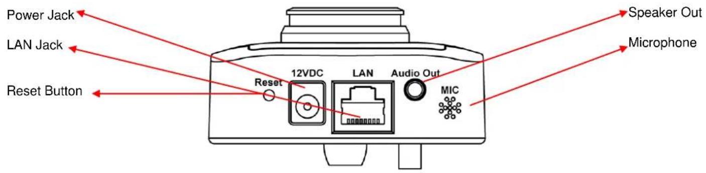
Reset Button: Press and hold for 5 seconds to reset the camera settings to factory default value.
Power Jack: Connect to power adapter for power supply.
LAN Jack: Connect to your local area network by network cable.
Speaker Out: Connect to external speaker
Back View
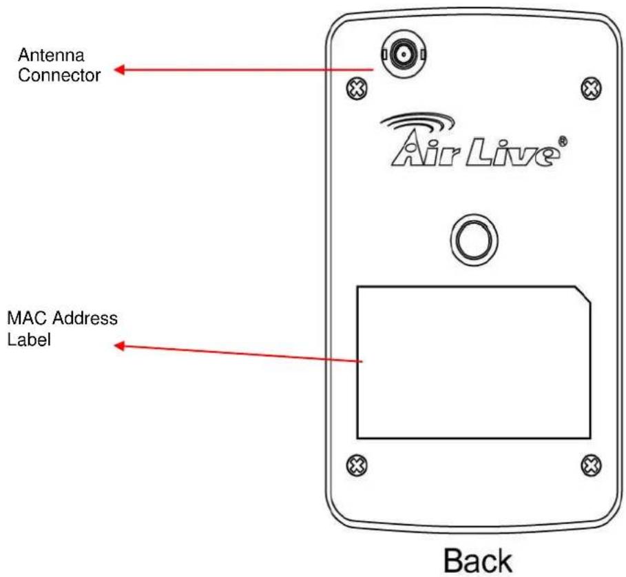
Tripod Connector: Connects to any standard tripod / camera wall holder.
MAC Address Label: Shows the MAC address of this IP camera. Useful when you can't locate the camera on the network.
1.5 Descriptions for LED Indicators
| LED Name | Status | Description |
| LAN | Off | Network cable is disconnected |
| On | Network cable is connected | |
| Flash | Transferring data via LAN port | |
| WLAN | Off | No wireless LAN activity |
| On | Transferring data via wireless LAN | |
| Power | Off | Camera is not powered (camera off) |
| On | Camera is correctly powered (camera on) |
1.6 Camera Installation
Please follow the following instructions to set your IP camera up.
- Unpack the product package and check if anything's missing.
- Connect the antenna to the antenna base, which is located at the top of this IP camera.
- Plug the power adapter to wall socket, and connect the power connector to the power jack located at the bottom of the IP camera.
- Connect the Ethernet cable to your local area network, and connect the other end to the LAN jack of this IP camera.
NOTE: You can skip this step if you plan to use wireless LAN only.
-
Connect your tripod / camera holder, and point the camera to the place you wish to monitor.
-
Connect the external speaker's audio cable to 'Speaker' jack located at the bottom of this IP camera.
If you don't need audio support, you can skip this step.
1.7 Locate the IP Address of this IP Camera
Default IP address of this IP camera is 192.168.2.3. If you wish to assign another IP address to this IP camera, you have to log onto the web configuration interface of the camera first.
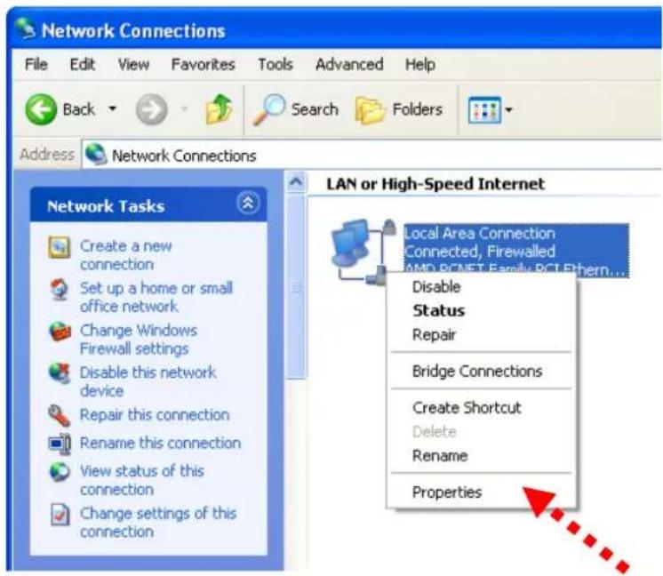
If the left three fields of the IP address of your computer is not 192.168.2, you'll have to change the IP address of your computer first:
1. Click 'Start' -> 'Control Panel'

2. Double-click 'Network Connections' icon.

- Right-click 'Local Area Connection', and click 'Properties'.
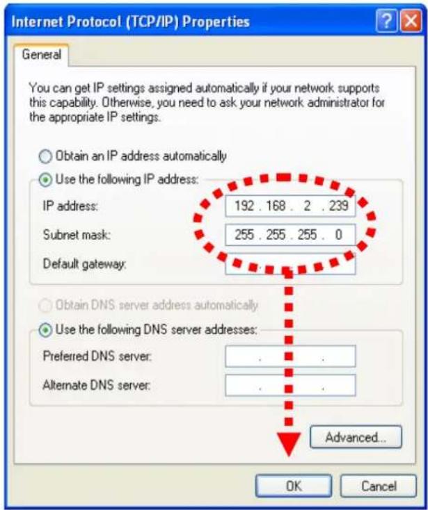
- Select 'Internet Protocol (TCP/IP)', then click 'Properties'.

- In 'IP address' field, please fill in any IP address begins with '192.168.2', and ends with a value greater than 2 and less than 254 (You can use the example in the picture '192.168.2.339'). In Subnet mask field, please fill '255.255.255.0'. Please keep all other fields empty, and click 'OK'.
If you changed the IP address of this IP camera and you forget it, there're 2 methods to recover it:
a. Press and hold the 'Reset' button located at the bottom of this IP camera, to clear all settings of the IP camera and reset the IP address back to 192.168.2.3. You'll lose all settings in the IP camera.
b. Ask network administrator to check the DHCP release table, if the camera was set to obtain the IP address by DHCP, a new record will be added to DHCP release table on DHCP server when the IP camera is connected to the local area network.
1.8 Log Onto Web Management Interface
Make sure the IP camera is correctly powered (Power LED is on), and then launch Internet Explorer and type the IP address of the IP camera in address bar of Internet Explorer. You should be prompted to input the user name and password:

Default user name is 'admin' (in lower case) and password is 'airlive'. Click 'OK' to continue after user name and password has entered.
If you're rejected, maybe the password has been modified previously. This should not happen if this is a newly-purchased camera, however, if you get the camera from someone else, the password would be changed. Please try to obtain the correct user name / password, or you'll have to reset the camera.
After logged on, you should see the following messages at the top of Internet Explorer:

This IP camera requires a special ActiveX control (A.K.A. 'Plugin') to work. Please click on the message, and select 'Install ActiveX Control...':

When you're prompted, click 'Install' to continue.

You should be able to see the image from camera now:

Note: If you see one of these messages (or both):

OR
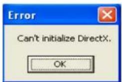
Your computer may not have the display capability that this IP camera requires, or you don't have Microsoft DirectX® installed. Please download Microsoft DirectX® from Microsoft's website (http://www.microsoft.com), and try again.
In some cases, your computer is able to display the image from IP camera correctly, but you'll still see these messages. If this happens, just ignore them.
Chapter II: Using Web Management Interface
2.1 Camera Settings
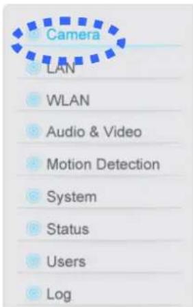
The first menu after you logged onto web management interface is 'Camera', and this is the only menu you can see the real-time image from camera.

You can always back to this menu by clicking 'Camera' on the top of web management interface.
The descriptions of every setting in this menu will be given below:
| Item | Description |
| Video Format | Specifies video encoding format. You can choose MPEG4 or MJPEG (Motion-JPEG).MPEG4 mode also supports motion detection (see chapter 2.2.1). |
| Speak to IPCam | If your computer is equipped with a microphone, you can press and hold this button and speak to the microphone. Your voice will be transmitted to the external speaker connected to the IP camera. This makes the IP camera become a network telephone, and you can talk to the people there.Please note that your voice will only be transmitted during the time you press and hold the ‘Speak to IPCam’ button. When you release the button, your voice will not be transmitted to IP camera.(If ‘Speak to IPCam’ button is grayed out, you have to activate audio function of this IP camera before you can use this function - see chapter 2.4 for detailed instruction). |
| Snapshot | Take a snapshot picture and save the picture to your computer’s hard drive. |
| Record | Start video recording and save recorded video clip to your computer’s hard drive. |
2.2.1 Motion Detection
When you're using 'MPEG4' encoding format, you can use motion detection function. When a motion is detected, the IP camera will take a picture automatically.
To setup motion detection, please select 'MPEG4' as encoding format, and right-click on the image. A pop-up menu will appear:

TIP: You can setup motion detection area here; however, you have to enable motion detection function of this IP camera before it really works. Please refer to chapter 2.6 to see detailed instructions for how to enable this function.
Please click 'Motion Detection' in pop-up menu, and a new setup menu will appear:
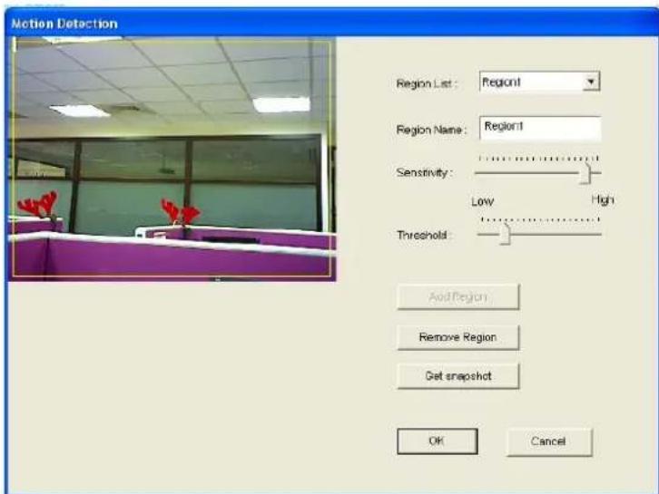
The IP camera will display the image of the area that IP camera points to at the left. The motion detection area must be rectangle, and cover the area you want to use motion detection function.
You can define a new motion detection region by mouse cursor:
- Click and hold left mouse button at the start point of rectangle on the image.
- Drag the mouse cursor, to define a rectangle.
- When you think the rectangle meets your needs, release left mouse button.
If you're not satisfied with the area that covered by the rectangle you just drawn, just repeat step 1 to 3 to establish a new rectangle. Then, click 'Add Region' to add a new region to your motion detection region list.
The descriptions of every setting in this menu will be given below:
| Item | Description |
| Region List | Lists all existing motion detection regions. You can define up to three pre-defined region. |
| Region Name | When you define a new region by mouse cursor, a default region name will appear here automatically (named by the size of the region you defined). You can change the name to the one you want to use by keyboard. |
| Sensitivity | Define the sensitivity of motion detection. When the sensitivity is lower, the IP camera will take a picture only when a numerous changes in the area are detected. If you want the IP camera to record all tiny changes in the motion detection area you defined, use a higher sensitivity setting. |
| Threshold | When the threshold is high, the IP camera will take a picture only when a numerous motion is detected. If you want the IP camera to record any motion in the motion detection area you defined, use a lower threshold setting. |
| Add Region | When you defined a new region by mouse cursor, click this button to add a new region to ‘Region List’, and use the name listed at ‘Region Name’ as new region’s name. |
| Get snapshot | If you moved the IP camera, or the objects that IP camera faces to is moved, you can click this button to get a new snapshot of the area that IP camera faces to, so you can decide how to |
When you finish with setting up motion detection region, click 'OK' to start motion detection, or click 'Cancel' to discard all settings you just made, and motion detection function will not be activated.
2.2.2 Mute Audio
This IP camera will transmit all sound received by built-in microphone to your computer by default. If you don't want to hear it, you can mute audio for a while.
To mute audio, please select 'MPEG4' as encoding format, and right-click on the image. A pop-up menu will appear:
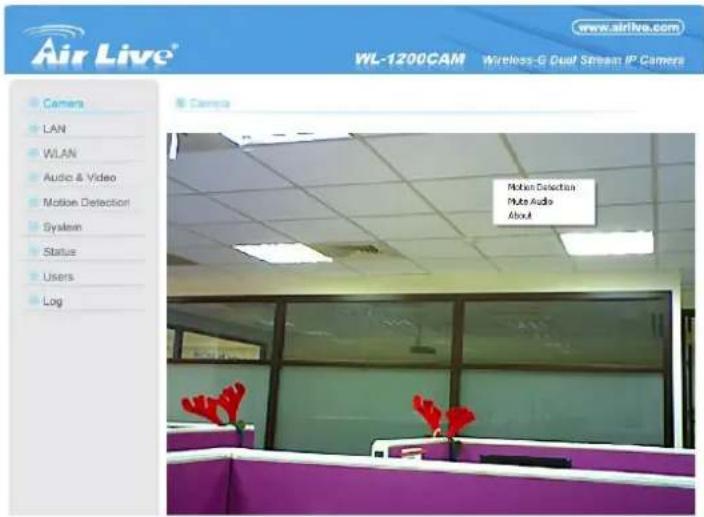
Click 'Mute Audio' to mute audio. A check will appear in front of 'Mute audio' to indicate that sound received by IP camera's microphone will not be transferred to your computer. Click 'Mute audio' again to hear the sound received by IP camera's microphone again.
2.2.3 About
This function will provide you with the version number of current IP camera plugin, which is useful when you need online support.
To see version information, right-click on the image. A pop-up menu will appear:

Select 'About' and the version information will appear:

2.2 LAN Settings
All network-related settings can be found in this menu, and you have to specify TCP/IP parameters in this menu if you want to change IP address, use PPPoE, Dynamic DNS, and activate UPnP function.
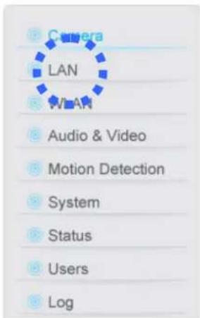
You can access this menu by clicking 'LAN' on the top of web management interface.
2.2.1 IP Address
You can define IP address and select the port number you wish to use here.
© LAN
Network Type :
DHCP
Static IP Address
IP Address :
192.168.2.3
Subnet Mask:
255.255.255.0
Gateway:
192.168.2.1
Primary DNS :
168.95.1.1
Secondary DNS :
The Ground Truth image displays a single, solid horizontal line. According to Rule 2 (UNDERSCORE & LINE RULES), this is a stylistic or background line, not a placeholder underscore. Therefore, the OCR result must ignore it and output nothing or only meaningful text. The provided OCR content is "____", which consists of four underscores. This is an incorrect interpretation of the line as a placeholder, violating the rule that stylistic lines must be ignored. The OCR has hallucinated underscores where none should exist based on the GT's visual context. Hence, the OCR result is inconsistent with the Ground Truth.
Video Port:
4321
HTTP Port:
80
Apply
The descriptions of every setting in this menu will be given below:
| Item | Description |
| Network Type | This camera can obtain the IP address from DHCP server automatically (if you have one), or set a fixed IP address. Select ‘DHCP’ to obtain IP address automatically or ‘Static IP Address’ to assign this IP camera with a fixed IP address.When ‘DHCP’ is selected, IP address parameters below will be grayed out. |
| IP Address | Specify the IP address for this IP camera here. |
| Subnet Mask | Specify the subnet mask for this IP camera here. |
| Gateway | Specify the gateway address of the local network here. |
| Primary DNS | Specify the IP address of DNS server here. Please input IP address only. If you don’t know the address of DNS server, ask network administrator or your ISP for help. |
| Secondary DNS | Specify the IP address of backup DNS server here. When primary DNS is unreachable, IP camera will use the IP address specified here as DNS server.This field is optional. |
| AV Control Port | Specify the port number of video transfer here. If you have firewall on your network, you need to allow computers on Internet to access this port number of the IP address of IP camera, or you’ll not be able to view video from Internet. |
| HTTP Port | Specify the port number of web management interface here. If it’s not 80, you’ll have to add ‘:port’ after the IP address / hostname of this IP camera.For example, if the HTTP port number you specified here is 90 and the IP address of IP camera is 10.20.20.30, then you have to input ‘http://10.20.20.30:90’ in the address bar of Internet explorer. |
Click 'Apply' to save settings and make the new settings take effect.
2.2.2 PPPoE
If the ISP requires you to connect to the Internet by PPPoE, you can specify PPPoE username and password here.
© PPPoE
Enable PPPoE :
User Name :
Password:
MTU:

The descriptions of every setting in this menu will be given below:
| Item | Description |
| Enable PPPoE | Select ‘Enable’ to activate PPPoE function of this IP camera, select ‘Disable’ to disable it. |
| User Name | Input the PPPoE username assigned by your ISP here. |
| Password | Input the PPPoE password assigned by your ISP here. |
| MTU | Input the MTU (Maximum Transmission Unit) given by your ISP here. Ask your ISP if you don’t know what value you should input here, or use default value. |
Click 'Apply' to save settings and make the new settings take effect.
2.2.3 Dynamic DNS
If your ISP does not give you a fixed Internet IP address (i.e. the Internet address you're using when you access the Internet is not always the same – ask your ISP for detailed information), you can use this function to help you locate the IP address of this IP camera when you're away from home or office.
Before you can use this function, you'll need to apply for an account at dyndns.org (http://www.dyndns.org). Detailed instructions of how to apply a new account can be found on dyndns.org's website.
Dynamic DNS
The descriptions of every setting in this menu will be given below:
| Item | Description |
| Enable DDNS | Select ‘Enable’ to activate Dynamic DNS function of this IP camera, select ‘Disable’ to disable it. |
| Provider | Select dynamic DNS service provider here. Only dyndns.org is available currently. |
| Host Name | Input dynamic DNS host name here. |
| User Name | Input dynamic DNS user name here, must be the same as the one you applied on dyndns.org. |
| Password | Input dynamic DNS password here, must be the same as the one you applied on dyndns.org. |
Click 'Apply' to save settings and make the new settings take effect.
2.2.4 UPnP
When UPnP function is activated, all UPnP-compatible computers / network devices will be able to discover this IP camera automatically (only those in the same local network).
This function is useful and you don't have to remember the IP address of this IP camera. Simply open 'Network neighbor' and it's there!

Enable UPnP :
Enable Disable
Apply
The descriptions of every setting in this menu will be given below:
| Item | Description |
| Enable UPnP | Select ‘Enable’ to activate UPnP function of this IP camera, select ‘Disable’ to disable it. |
Click 'Apply' to save settings and make the new settings take effect.
After UPnP function is activated, a popup message will appear:
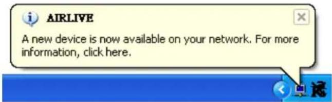
Click the message to open 'My Network Places', and you'll see the IP camera:

You can double-click the icon to launch Internet Explorer and log onto IP camera's web management interface directly.
2.2.5 LoginFree
You can specify a filename here, and everyone who know this filename can gain access to the picture captured by the IP camera with this name with .jpg file extension.
For example, if the filename you specified here is 'loginfree' and your IP camera's IP address is '192.168.2.3', then everyone on the network can access to the picture taken by the IP camera at 'http://192.168.2.3/loginfree.jpg'.
This function is for convenience only, and anyone who knows this filename will be able to see the picture taken by your IP camera. Please think again before you use this function.
© LoginFree
Filename :
loinfree
.jpg
Apply
The descriptions of every setting in this menu will be given below:
| Item | Description |
| LoginFree | Specify the file name of the picture here. If you want to disable this function, leave it blank. |
Click 'Apply' to save settings and make the new settings take effect.
2.3 WLAN Parameters (For wireless model only)
If you wish to use wireless network instead of wired network connection, you have to set wireless LAN parameters here.
Wireless LAN

| Connect | SSID | MAC Address | Signal | Channel | Encryption | Network Type |
| Og | 00:0D:54:A4:50:8D | 61 | 3 | WEP | Infrastructure | |
| Og | airlive | 00:0E:2E:44:82:78 | 89 | 6 | WPA2PSK(AES) | Infrastructure |
| Og | 00:18:39:90:5D:70 | 69 | 6 | WEP | Infrastructure | |
| Og | WLAP01 | 00:0D:0B:6D:21:9F | 63 | 10 | WEP | Infrastructure |
| ◆ SSID : airlive | ||||||
| ◆ Channel : 1 | ||||||
| ◆ Basic Rate : Auto | ||||||
| ◆ Authentication : WPA2-PSK | ||||||
| ◆ Encryption Type : AES | ||||||
| ◆ WPA Pre-Shared Key :********** | ||||||
| ◆ WEP Key Length : 64-Bit | ||||||
| ◆ WEP Key Format : HEX | ||||||
| ◆ Default Key : 1✓ | ||||||
| ◆ WEP Key 1 : | ||||||
| ◆ WEP Key 2 : | ||||||
| ◆ WEP Key 3 : | ||||||
| ◆ WEP Key 4 : | ||||||
You can access this menu by clicking 'WLAN' on the top of web management interface.

The descriptions of every setting in this menu will be given below:
| Item | Description |
| Wireless Connection | Select ‘Enable’ to activate wireless network function of this IP camera, select ‘Disable’ to disable it. |
| Network Type | Select the network type of wireless connection.Available options are ‘Infrastructure’ (Connect the IP camera to a wireless access point), and ‘Adhoc’ (This IP camera will become a stand-alone wireless network point, other wireless computers / devices can discover this IP camera and connect to it without wireless access point).You can set to ‘Adhoc’ when you don’t have any wireless access point, but your computer has wireless network card. Set to ‘Infrastructure’ when you have wireless access point, and you have computers with wired network connection. |
| Available Networks | Here shows all wireless access points found by this IP camera. Please note not all access points will be displayed at the same time, if the access point you wish to connect does not appear, you may have to click ‘Refresh’ button for several times until it appears.The descriptions of all fields is listed below:Connect: You can select the wireless access point you wish to connect here.**SSID: the SSID of all found wireless access points will be shown here. Some wireless access point may hide their SSID, in this case, you have to identify them by their MAC address.MAC Address: If you there are many wireless access points in proximity or some wireless access point hides it’s SSID, you can use MAC address to distinguish them.Signal: Shows the radio signal strength in percent.Channel: Shows the radio channel of this wireless access point.Encryption: Shows the encryption type used by this wireless access point. You must use the same encryption type if you wish to connect to a certain wireless access point. If the wireless access point does not use encryption, ‘Disabled’ will be displayed here.Network Type: Shows the network type of a certain wireless access point (Infrastructure or Adhoc). |
| SSID | Input the SSID of the wireless access point you wish to connect. It should be less than 32 alphanumerical characters.When you select a wireless access point above, it’s SSID will be filled in this field automatically. However, if the SSID is not displayed (the wireless access point you selected choose to hide it’s SSID), you have to know it’s SSID and input it here, or you will not be able to connect it. |
| Channel | Select the radio channel you wish to use here. When network type is ‘Infrastructure’, the radio channel is auto-selected according to the channel that wireless access point uses. You can only select the channel number when network type is ‘Adhoc’. |
| Basic Rate | Select the maximum wireless data transfer rate here, from 1Mbps to 54Mbps. Maximum transfer rate for 802.11b wireless network is 11Mbps, and maximum transfer rate for 802.11g wireless network is 54Mbps.It’s recommended to select ‘Auto’, so the data transfer rate will varyaccording to the actual signal strength and quality. |
| Authentication | Select the wireless authentication here, and this setting must be the same with the wireless access point you selected.When you select a wireless access point from the list, it's authentication type will be selected automatically, and you should not modify it or you will not be able to connect to the wireless access point you selected.Available options are: None (no authentication), Open System, Shared Key System, WPA-PSK, WPA2-PSK, and WPANone (the last one is only for Adhoc). |
| Encryption Type | Select the wireless encryption type here, and this setting must be the same with the wireless access point you selected.When you select a wireless access point from the list, it's encryption type will be selected automatically, and you should not modify it or you will not be able to connect to the wireless access point you selected.Available options are: None, WEP, TKIP and AES. The options available here will vary depends on the authentication type you selected above. If an authentication type does not support need encryption, this field will be grayed out. |
| WPA Pre-Shared Key | Input the WPA pre-shared key here.This field is only available when authentication type is WPA-PSK or WPA2-PSK, and will be grayed out when other authentication type is selected. |
| WEP Key Length | Please select the key length when you use WEP encryption. Available options are 64-bit and 128-bit.Selecting '128-Bit' is safer, however, it would make the network a little bit slower.If the key length is 64-bit, you should input 10 HEX characters or 5 ASCII characters, like 112233aabb (HEX) or MYWEP (ASCII).If the key length is 128-bit, you should input 26 HEX characters or 13 ASCII characters, like 11223344556677889900abcdef (HEX) or myweppassword (ASCII). |
| WEP Key Format | Select the Key Format of WEP key here. Available options are 'HEX' and 'ASCII'.When you select 'HEX' WEP key format, you can only use numbers (0 to 9), and alphabet a to f as WEP key; when you select 'ASCII' WEP key format, you can use all alphanumeric characters, and is case sensitive. |
| Default Key | Select the default key set that is IP camera should use against the wireless access point when WEP encryption is used.Available options are 1 to 4. |
| WEP Key 1 | Input the 1st set of WEP key here. At least a set of WEP key is required and you should use 1st WEP key if you only have one WEP key. |
| WEP Key 2 | Input the 2nd set of WEP key here. |
| WEP Key 3 | Input the 3rd set of WEP key here. |
| WEP Key 4 | Input the 4th set of WEP key here. |
Click 'Apply' to save settings and make the new settings take effect.
2.4 Audio/Video
You can specify the video and audio parameters of this IP camera here.
Dual Mode
Default Video Format :
MPEG4
Apply
MPEG4
Video Resolution :
VGA (640 × 480)
Video Quality:
CBR 2 Mbps
Video Frame Rate :
VBR Highest
Apply
© MJPEG
Video Resolution :
VGA (640 × 480)
Video Quality:
Highest
Video Frame Rate :
30
Apply
Audio
Audio Function :
Enable Disable
Microphone Volume :
80
Audio Line-Out Volume :
80
Apply
2.4.1 Dual Mode
This IP camera supports two video encoding formats: MPEG4 and MJPEG. You can select the encoding format from one of them.
Dual Mode
Default Video Format :
MPEG4
Apply
The descriptions of every setting in this menu will be given below:
| Item | Description |
| Default Video Format | Specify default video encoding format of this IP camera here. Available options are MPEG4 and MJPEG. |
Click 'Apply' to save settings and make the new settings take effect.
2.4.2 MPEG4
If you selected 'MPEG4' as the video encoding format of this IP camera, you can specify the parameters of MPEG4 video encoder here.
© MPEG4
Video Resolution :
Video Quality :
Video Frame Rate :


The descriptions of every setting in this menu will be given below:
| Item | Description |
| Video Resolution | Specify video resolution of MPEG4 video encoder. Available options are VGA and QVGA resolution. VGA resolution provides more details than QVGA, but requires more network bandwidth. |
| Video Quality | 1. Specify video encoding rate of MPEG4 video encoder.2. CBR: Available options are from 200Kbps to 2Mbps. Greater video bit rate provides better video quality, but requires more network bandwidth.3. VBR: Available from Lowest/ Low/ Normal/ High/ Highest |
| Video Frame Rate | Specify video refresh rate of MPEG4 video encoder. Higher video refresh rate provides more details about motion, but requires more network bandwidth.CAUTION: Choosing a low frame rate will save bandwidth, but may not be able to capture every motion if the object that IP camera points to is moving fast. |
Click 'Apply' to save settings and make the new settings take effect.
2.4.3 MJPEG
If you selected 'MJPEG' as the video encoding format of this IP camera, you can specify the parameters of MPEG4 video encoder here.

MJPEG
Video Resolution :
Video Quality :
Video Frame Rate :
VGA (640 x 480)
Highest
30
Apply
The descriptions of every setting in this menu will be given below:
| Item | Description |
| Video Resolution | Specify video resolution of MJPEG video encoder. Available options are VGA, QVGA, and QQVGA resolution. VGA resolution provides more details than QVGA and QQVGA, but requires more network bandwidth. |
| Video Quality | Specify video encoding quality of MJPEG video encoder. There are five levels of video quality from highest to lowest. Higher video quality provides better video quality, but requires more network bandwidth. |
| Video Frame Rate | Specify video refresh rate of MJPEG video encoder. Higher video refresh rate provides more details about motion, but requires more network bandwidth.CAUTION: Choosing a low frame rate will save bandwidth, but may not be able to capture every motion if the object that IP camera points to is moving fast. |
Click 'Apply' to save settings and make the new settings take effect.
2.4.4 Audio
This IP camera supports audio function, that is, when external speaker is connected to this IP camera, you can talk to the people in front of the IP camera like using a telephone, when your computer is equipped with speaker and microphone.
Using audio function requires additional bandwidth. If your network bandwidth is not enough, you may not be able to use audio function smoothly. In this case, you can try a lower video resolution / quality / frame rate, to save more bandwidth for audio function.

Audio
Audio Function :
Microphone Volume :
Audio Line-Out Volume :

Enable

Disable


Apply
The descriptions of every setting in this menu will be given below:
| Item | Description |
| Audio Function | Choose ‘Enable’ to enable audio function of this IP camera, or choose ‘Disable’ to disable it. |
| Microphone Volume | Specify the microphone volume. If you found that you can not hear the sound from IP camera clearly, you may increase the number here. |
| Audio Line-Out Volume | Specify the line-out volume here. If you found that the people encounters difficult when listening to you, you may increase the number here.CAUTION: Using a high number here with an amplified external speaker may cause hearing problem to the people standing in front of the speaker, or may cause damage to the speaker itself. |
Click 'Apply' to save settings and make the new settings take effect.
2.5 Email & FTP
This IP camera is capable to send an Email or perform FTP upload with captured image, when a motion is detected. This is very convenient since IP camera will guard the environment automatically for you, and you don't have to look at the monitor all the time.
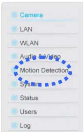
You can access this menu by clicking 'Motion Detection' on the top of web management interface.
The instructions of Email and FTP settings will be given below.
2.5.1 Email Settings
These settings are used to send the captured picture via Email:
◆ Recipient E-Mail Address :
SMTP Server:
Sender E-Mail Address :
SMTP Authentication :
User Name :
Password:


The descriptions of every setting in this menu will be given below:
| Item | Description |
| Recipient E-Mail Address | Input the email recipient's Email address here. |
| SMTP Server | Input the IP address or host name of the SMTP server (the server that delivers the Email for you) here.If you don't know, please refer to the SMTP server you're using in your Email software (like Outlook, Outlook Express etc.), or ask your network administrator or ISP. |
| Sender E-Mail Address | Input the Email address of mail sender, this will help you to identify the Email sent by this IP camera by sender's Email address.NOTE: Some mail server would reject to deliver the Email from unknown sender, it's recommended to input your own Email address here, or any other actual one. |
| SMTP Authentication | Some SMTP server requires mail senders to be authenticated before they can send Email. If your SMTP server requires you to do so, please select 'Enable', or select 'Disable' to disable it. If you don't know, please refer to the SMTP server you're using in your Email software (like Outlook, Outlook Express etc.), or ask your network administrator or ISP. |
| User Name | Please input the user name of SMTP server here, if your SMTP server requires the use of authentication. |
| Password | Please input the password of SMTP server here, if your SMTP server requires the use of authentication. |
Click 'Apply' to save settings and make the new settings take effect.
After that, you can click 'Send a test email' to send a testing Email to the address you set here, so you can make sure the setting you specified here is correct and working.
2.5.2 FTP Settings
These settings are used to send the captured picture by FTP:
FTP Configuration
FTP Server :
FTP Port :
User Name :
Password:
Remote Folder :
Passive Mode :

The descriptions of every setting in this menu will be given below:
| Item | Description |
| FTP Server | Input the IP address or host name of the FTP server you wish to use here. |
| FTP Port | Input the port number of the FTP server you wish to use here. |
| User Name | Input the user name of the FTP server you wish to use here. |
| Password | Input the password of the FTP server you wish to use here. |
| Remote Folder | Input the remote folder name on the FTP server here. If nothing is specified here, all uploaded image files will be placed in FTP server's root directory.Please ask FTP server's administrator to know which folder you should use. Certain user name may have restrictions and therefore can not place the file in the directory not owned by the user. |
| Passive Mode | Select ‘Enable’ to use passive mode to send file, or select ‘Disable’ to not to use passive mode to send file.Some FTP servers require passive mode, if you don't know, please ask FTP server's administrator; most of FTP servers will work fine with both modes, but if you found that non-passive mode is not working, you can try to use passive mode. |
Click 'Apply' to save settings and make the new settings take effect.
After that, you can click 'Upload a test file' to send a file to the FTP server you set here, so you can make sure the setting you specified here is correct and working.
2.6 Motion Detection
Motion detection function makes this IP camera become your non-stop guard. You don't have to waste all the time monitoring the images from the camera, and camera will detect all motions for you. Once motion is detected, a captured image will be sent to you by Email or via FTP.
© Motion Detection
◇ Motion Detection Enable :
○ Enable ◦ Disable
◆ Next Event Detected Interval :
5 seconds
Recording Time :
3 seconds
Send snapshot file to E-Mail :
Yes No
E-Mail Subject:
Motion Detection Notification
Send snapshot file to FTP :
Yes No
Apply
You can access this menu by clicking 'Motion Detection' on the top of web management interface.

The descriptions of every setting in this menu will be given below:
| Item | Description |
| Enable Motion Detection | Select ‘Enable’ to start motion detection, and select ‘Disable’ to disabled it. |
| Next Event Detected Interval | Specify the time interval between two motion detections in seconds. If a motion is detected after last detection time, and before next detection time, nothing will be send by Email or via FTP.Please specify a time interval that suites your need. If the time interval is too long, you may not be able to know what is happened between time interval; if the time interval is too short, you may receive too much unnecessary images, and consumes too much disk storage spaces on Email and / or FTP server. |
| Recording Time | Set the maximum recording time of a video clip when motion is detected. |
| Send snapshot file to Email | Select ‘Yes’ to send a picture to the Email address you specified in ‘E-Mail & FTP’ menu when a motion is detection, and select ‘No’ to disable this function. |
| E-Mail Subject | Set the subject of Email being sent here. This will help you to distinguish the Email sent by this IP camera from others. |
| Send snapshot file to FTP | Select ‘Yes’ to send a picture to the FTP server you specified in ‘E-Mail & FTP’ menu when a motion is detection, and select ‘No’ to disable this function. |
Click 'Apply' to save settings and make the new settings take effect.
2.7 System
The system menu allows you to set some system-specific parameters, like password and time setting. You can also upgrade the firmware of this IP camera, to make new functions available on this IP camera. You may also clear all settings or reboot the IP camera here.
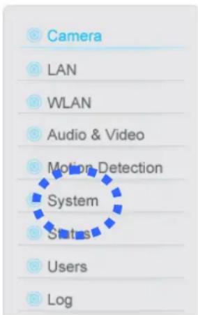
You can access this menu by clicking 'System' on the top of web management interface.
2.7.1 Camera Information
Camera information allows you to set the name and administrator's password of this camera.
© Camera Information
Camera Name :
Password:
Confirm Password :




The descriptions of every setting in this menu will be given below:
| Item | Description |
| Camera Name | Please specify the name of this IP Camera here. This can be used to identify your camera on the network when you have more than one IP camera in the same network.Default name begins with ‘IC-’ plus the last 6 characters of the MAC address of this IP camera. You can modify the name to the one you can remember and meaningful to you, but never give all IP cameras in the same network with same name. |
| Password | Please specify user name ‘admin’ ’s password here. (The one you need when you log onto web management interface and use ‘admin’ as user name. |
| Confirm Password | Please input the same password again, to make sure there’s no typo. |
Click 'Apply' to save settings and make the new settings take effect.
2.7.2 Date / Time Setting
This setting allows you to change the date and time of the real time clock in this IP camera. You can set the time manually, or use network time protocol (NTP) to set the time automatically.
Date / Time Setting

The descriptions of every setting in this menu will be given below:
| Item | Description |
| Set Date/Time manually | Please input the date and time you wish to set here.Date / time format is YYYY / MM / DD HH:MM:SSTime is in 24-hour format.You can click ‘Synchronize to PC time’ to use the time of the computer you’re using.Example: 24th August 2007 = 2007/ 08 / 24,and PM 9:24:30 = 21:24:30 |
| Time Zone | Please select the time zone of the country / city of resident from dropdown menu here. |
| NTP Server | Please input the IP address or host name of NTP server here. You can use default value ‘pool.ntp.org’, or ask your ISP for the IP address or host name, if they have one. |
Click 'Apply' to save settings and make the new settings take effect.
2.7.3 Utilities
This menu allows you to upgrade firmware, clear all settings, reboot the IP camera, and switch LED lights on/off.
© Utilities
Upgrade Firmware :

Reset To Factory Defaults :
Reboot Device :
LED Setting :
The descriptions of every setting in this menu will be given below:
| Item | Description |
| Upgrade Firmware | If you downloaded latest firmware file from our website, you can click ‘Browse’ button to pick the firmware file you wish to use. Then click ‘Upgrade’ button to start firmware upgrade procedure.It’s recommended to use wired Ethernet connection when you use this function, and DO NOT DISCONNECT OR CLOSE WEB BROWSER DURING UPGRADE! |
| Reset | Clear all settings in the camera. Please think again before you do this, and then click this button to reset all settings.NOTE: IP address will be reset to default value ‘192.168.2.3’ also.You’ll need to change the IP address setting of your computer if the IP address of your computer does not begin with ‘192.168.2’, and subnet mask is not ‘255.255.255.0’, or you’ll not be able to connect to this IP camera again. |
| Reboot Device | If you found the IP camera is responding slowly or behaves strange,you can click this button to try to reboot the IP camera, this may help. |
| LED Setting | Switch the LED light of this IP camera off, so ‘LAN’ and ‘WLAN’ LED on the IP camera will stop working, in case you don’t want other people know the camera is transferring data.You can click this button again to switch LED lights on again. |
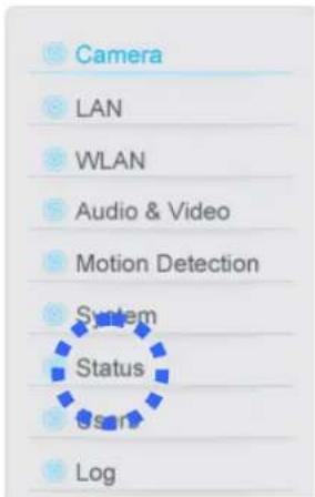
2.8 Status
This menu provides all information about this IP camera, like firmware version, system uptime, date / time, and network information.
You can access this menu by clicking 'Status' on the top of web management interface.
Status
Firmware Version: v1.13 (Feb 14 2008 17:13:59)
Device Uptime : 10 min 14 sec
System Time : 2008/02/19 18:07:22
© LAN
IP Address: 192.168.2.3
◇ Subnet Mask: 255.255.255.0
Gateway: 192.168.2.1
DNS Server: 168.95.1.1
MAC Address : 00:0E:2E:FD:59:B8
AV Control Port: 4321
AV Data Port: 4322
Web Port: 80
© PPPoE
Link Status: Disconnected
IP Address :
Subnet Mask:
Gateway:
DNS Server :
2.9 Users
If you wish to allow other people to view the image captured by this camera, but don't want to allow them to modify system settings, you can give them user-level user name and password, so they can only view the image and can not change any system setting. When they want to click menus other than 'Camera', they will see the following message informing that they don't have permission to do that:

Access Denied
This IP camera supports up to 4 users.
You can access this menu by clicking 'Users' on the top of web management interface.

Please note: only one user (including administrator) will be able to view the image of IP camera at the same time.
The descriptions of every setting in this menu will be given below:
| Item | Description |
| User (1 - 4) | Select ‘Enable’ to enable this user (allow him / her to login), and select ‘Disable’ to disallow him / her to login.Selecting ‘Disable’ won’t erase the user name and password, so you can select ‘disable’ to disallow a user from logging in temporarily, without erasing it’s account information. |
| Login | Specify the user name here. Please use alphanumeric characters (0 to 9, A to Z, and a to z). Not using symbols and space. |
| Password | Specify the password for this user here. |
| Confirm Password | Specify the password for this user here again. |
Click 'Apply' to save settings and make the new settings take effect.
2.10 Log
All activities of this IP camera will be logged, and you and enter 'Log' menu to view these logs.
You can access this menu by clicking 'Log' on the top of web management interface.

Click 'Refresh' to get latest update.
System Log
![Refresh 1970/01/01 00:00:03 System startup [ v1.13 (Feb 14 2008 17:13:59) ] 1970/01/01 00:00:03 Set microphone volume to 80 1970/01/01 00:00:04 Set Line-Out volume to 80 1970/01/01 08:00:05 Opened /dev/pl_grab successfully 1970/01/01 08:00:05 Opened /dev/pl_enc successfully (MPEG4) 1970/01/01 08:00:…](/content/2026/05/1091394/images/002f1dfe154fdb5485ba3cde4416faf195e1c5bf9ce7052f0e2c149750dc9d44.jpg)
Chapter III: Windows-Based Utility
3.1 Install Windows-based Utility
To install windows-based Utility of this IP camera, please put the supplied CD-ROM into the CD-ROM drive of your computer. The following message should appear within 1 minute:
**missing autorun capture
If the autorun function of your computer is not enabled, or nothing appears after CD-ROM has been loaded, you can click 'My Computer' icon and locate your CD-ROM drive (labeled as 'CD-ROM Drive', 'CD-RW Drive', 'DVD-ROM Drive', or 'DVD-RW Drive'), then double-click 'setup.exe' to activate utility setup procedure manually.
Follow the following instructions to install utility:
- Click 'Next' to start setup procedure:

Click 'Next' to install the utility to default location (folder). To change folder, click 'Change' and pick another folder you wish to use.

- Click 'Install' to install utility to the folder selected in previous step:

Setup procedure may require several minutes, please be patient.

- When you see this message, the setup procedure is completed. Click 'Finish' to exit.

- If you have Windows Defender (Windows XP) or other 3 rd party firewall software, you may see the following (or similar) message:

Please click 'Unblock' (or similar option) to let IP camera Utility pass the firewall, or the IP camera utility may not be able to function properly.
- A new folder named 'IP Camera' in 'All Programs' will be created: Admin Utility, Camera Viewer, and Uninstall. You can use these 3 utilities to connect to the IP camera and use the functions of the camera without web browser.

3.2 Locate Camera on Local Network and Network Setting
Admin utility will launch automatically after installation is complete. If not, please launch 'IP Camera Admin' from 'IP Camera' group in 'All Programs' by yourself. If the IP camera is correctly installed and connected to your network, you should see something similar like this:

All found cameras will be displayed at the left of admin utility, which begins with 'IC-' and the last 6 characters of IP camera's network MAC address (the 'IC-3010AF' item in this example). You can check the MAC address label at the back of the camera to distinguish from different cameras, if you have more than one IP camera connected to your network.
If no camera is found, please go to section 1-6 and 1-7 and check if everything is correctly configured.
You will see a letter located at the left of camera's name ('N' in the example above), which indicates the status of each IP camera:
'N' indicates the camera is newly found and not configured;
‘D’ indicates the camera is disconnected, and
'M' indicates the camera is connected.
Please select a camera, and the camera's current setting will be displayed at 'Information of Camera' section (right). You can click the '+' sign at the left of 'Network Information' and 'Wireless Information' to check respective settings of selected camera:
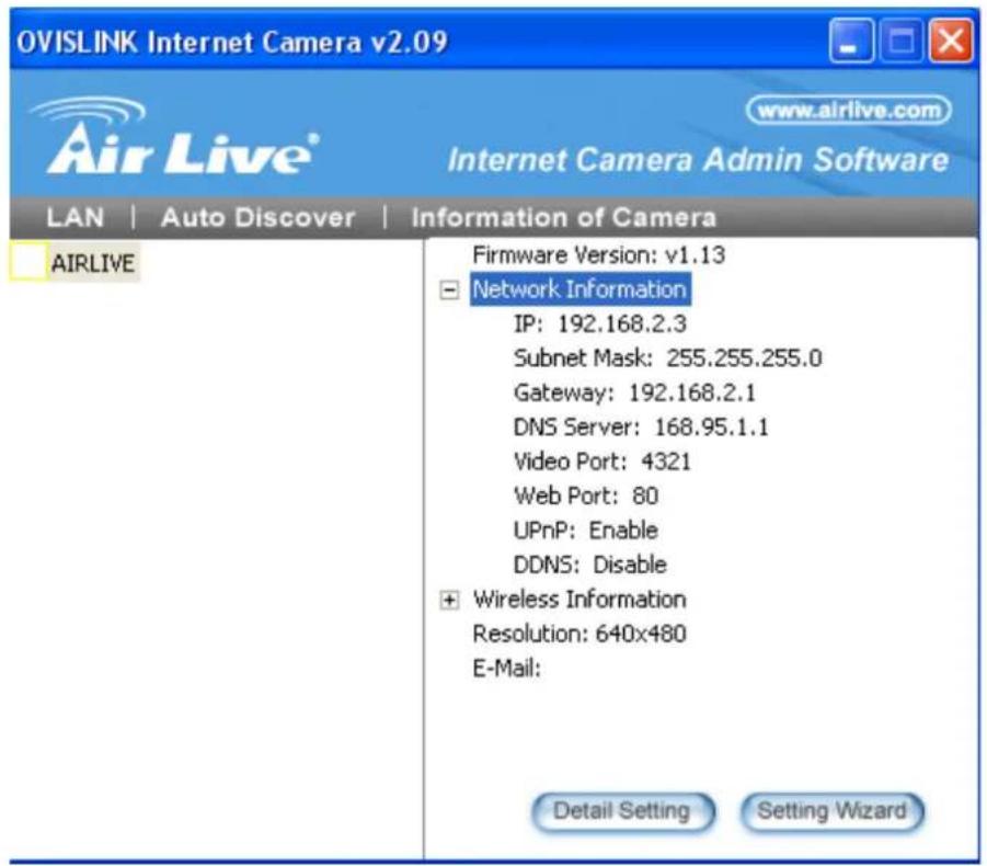
If you want to change these settings, please click 'Detail Setting' or 'Setting Wizard'.
If you only need to change the basic network setting, click 'Setting Wizard'. You'll be prompted to input user name and password:

The default user name is 'admin' (you can not change it), and the default password is 'airlive', and then click 'OK' to continue.

The descriptions of every setting in this menu will be given below:
| Item | Description |
| Internet Camera Name | The name of this IP camera. If you have more than one IP camera, it's suggested to use the place's name where camera is located, so you can identify the camera easily, like ‘Garden’ or ‘Front Door’. Spaces are allowed. |
| IP Address | Please specify the IP address you wish to assign to this IP camera. |
| Subnet Mask | Please specify the subnet mask you wish to assign to this IP camera. |
| Gateway | Please specify the IP address of the gateway of the your network. |
| Video Port | Please specify the port number for video transmission. |
When you finish setting, click 'Finish', and you'll be prompted that the camera is rebooting:

The following message will appear after few seconds, if you wish to connect to the IP camera and see the images captured by IP camera, click 'OK'; otherwise click 'Cancel' to exit.
AirLive WL-1200CAM User's Manual
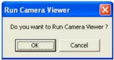
Please refer to section ** for detailed instructions of Camera Viewer.
3.3 Detail Setting
Please click 'Detail Setting' in admin software for detailed IP camera setting, and you'll be prompted to input user name and password:

The default user name is 'admin' (you can not change it), and the default password is 'airlive', and then click 'OK' to continue.
3.3.1 Network Settings
The 'Network Settings' tab lets you to configure the network settings of the IP camera.
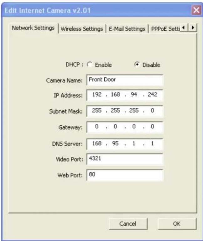
The descriptions of every setting in this menu will be given below:
| Item | Description |
| DHCP | Select ‘Enable’ to use DHCP to configure the IP address of this IP camera via DHCP server automatically; select ‘Disable’ to configure the IP address manually. |
| Camera Name | The name of this IP camera. If you have more than one IP camera, it's suggested to use the place's name where camera is located, so you can identify the camera easily, like ‘Garden’ or ‘Front Door’. Spaces are allowed. |
| IP Address | Please specify the IP address you wish to assign to this IP camera. |
| Subnet Mask | Please specify the subnet mask you wish to assign to this IP camera. |
| Gateway | Please specify the IP address of the gateway of the your network. |
| DNS Server | Please specify the IP address of the DNS server of your network. |
| Video Port | Please specify the port number for video transmission, default value is ‘4321’. |
| Web Port | Please specify the port number for web management interface, default value is ‘80’. |
After all settings are completed, click 'OK' to save settings, or click 'Cancel' to abort and discard changes.
3.3.2 Wireless Settings
The 'Wireless Settings' tab lets you to configure the wireless network settings of the IP camera.

The descriptions of every setting in this menu will be given below:
| Item | Description |
| Wireless Connection | Select ‘Enable’ to enable the wireless interface of this IP camera; select ‘Disable’ to switch wireless interface off. If the wireless interface is disabled, all setting items in this tab will be grayed out. |
| Available Network | Shows all wireless devices found, and their SSID (the name of wireless device) and signal strength. If the SSID of wireless device is hidden, the ‘SSID’ of the wireless device will appear blank. |
| Refresh | Click to search wireless devices again. Sometime a wireless device will not be shown before you click ‘Refresh’ for several times. |
| Connect | Connect to the selected wireless device in the list. If the wireless device requires authentication / encryption, you’ll be prompted to input required information. |
| Add to Profile | Save selected wireless device to profile. However, if the wireless device you selected requires authentication / encryption, you need to edit the profile and input required information before you can connect to the wireless device. |
| Add | Create a new profile. You’ll be prompted to input these information: |

Profile Name: Give the profile a name so you can distinguish from others.
SSID: Please specify the SSID of the wireless device you wish to connect; you MUST know the SSID of wireless device you wish to connect.
Channel: Select the radio channel number of this profile, must be the same with the wireless device you wish to connect.
Network Type: If the network device is a wireless access point, you should select 'Infrastructure'; if the network device is a computer, you can try 'Ad Hoc'.
Authentication Type: Set the authentication type required by the network device you wish to connect here (Select one from drop down menu).
Encryption Type: Select the encryption type required by the network device you wish to connect here, the content of drop down menu will vary depend on the authentication type you selected above.
WPA Pre-Shared Key: Input the WPA pre-shared key of the wireless device you wish to connect here. Must be the same with the setting of the wireless device you wish to connect, or you'll not be able to build connection. This option will be grayed out when encryption type is not WPA.
Key Length: Select the key length of WEP encryption. Must be the same with the setting of the wireless device you wish to connect.
Key Format: Key Length: Select the key format of WEP encryption.
| Must be the same with the setting of the wireless device you wish to connect.Default Key: Select the default encryption key of WEP encryption. Available options are Key 1 to Key 4; in most cases you should use Key 1, unless otherwise instructed.Key 1 to Key 4: Input the WEP encryption key here in respective field. In most cases only Key 1 is required.When you finish with setting, click ‘OK’ to save settings. | |
| Edit | You can edit the content of a selected profile. |
| Delete | You can delete a selected profile. You WILL NOT be prompted before deleting a profile, use with caution. |
| Activate | Activate selected profile (connect to the wireless device defined in the profile). |
After all settings are completed, click 'OK' to save settings, or click 'Cancel' to abort and discard changes.
3.3.3 E-Mail Settings
The 'E-Mail Settings' tab lets you to configure the E-mail alert settings of the IP camera. An E-mail will be sent to the address you specified here when the IP camera detects motion, so you can be alerted by E-mail anywhere & anytime.
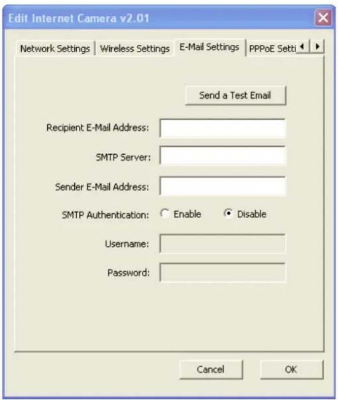
The descriptions of every setting in this menu will be given below:
| Item | Description |
| Send a Test Email | After the settings in this page is complete and saved (by clicking ‘OK’), you can click this button to send a test E-Mail to verify if these settings are correct and working. |
| Recipient E-Mail Address | Input the email recipient's Email address here. |
| SMTP Server | Input the IP address or host name of the SMTP server (the server that delivers the Email for you) here.If you don't know, please refer to the SMTP server you're using in your Email software (like Outlook, Outlook Express etc.), or ask your network administrator or ISP. |
| Sender E-Mail Address | Input the Email address of mail sender, this will help you to identify the Email sent by this IP camera by sender's Email address.NOTE: Some mail server would reject to deliver the Email from unknown sender, it's recommended to input your own Email address here, or any other actual one. |
| SMTP Authentication | Some SMTP server requires mail senders to be authenticated before they can send Email. If your SMTP server requires you to do so, please select ‘Enable’, or select ‘Disable’ to disable it. If you don't know, please refer to the SMTP server you're using in your Email software (like Outlook, Outlook Express etc.), or ask your network administrator or ISP. |
| User Name | Please input the user name of SMTP server here, if your SMTP server requires the use of authentication. |
| Password | Please input the password of SMTP server here, if your SMTP server requires the use of authentication. |
After all settings are completed, click 'OK' to save settings, or click 'Cancel' to abort and discard changes.
3.3.4 PPPoE Settings
The ‘PPPoE Settings’ tab lets you to setup the PPPoE account required to build a PPPoE (Point-to-Point Protocol over Ethernet) connection, primarily used by ADSL.
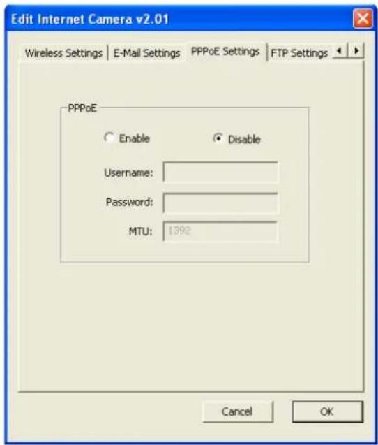
The descriptions of every setting in this menu will be given below:
| Item | Description |
| Enable PPPoE | Select ‘Enable’ to activate PPPoE function of this IP camera, select ‘Disable’ to disable it. |
| User Name | Input the PPPoE username assigned by your ISP here. |
| Password | Input the PPPoE password assigned by your ISP here. |
| MTU | Input the MTU (Maximum Transmission Unit) given by your ISP here. Ask your ISP if you don’t know what value you should input here, or use default value. |
After all settings are completed, click 'OK' to save settings, or click 'Cancel' to abort and discard changes.
3.3.5 FTP Settings
When the IP camera detects motion, besides E-Mail, it can send the captured file via FTP also. If you have a FTP server or has a FTP account with write permission, you can use FTP server to keep captured image.
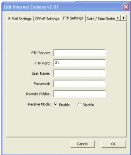
The descriptions of every setting in this menu will be given below:
| Item | Description |
| FTP Server | Input the IP address or host name of the FTP server you wish to use here. |
| FTP Port | Input the port number of the FTP server you wish to use here. |
| User Name | Input the user name of the FTP server you wish to use here. |
| Password | Input the password of the FTP server you wish to use here. |
| Remote Folder | Input the remote folder name on the FTP server here. If nothing is specified here, all uploaded image files will be placed in FTP server's root directory.Please ask FTP server's administrator to know which folder you should use. Certain user name may have restrictions and therefore can not place the file in the directory not owned by the user. |
| Passive Mode | Select ‘Enable’ to use passive mode to send file, or select ‘Disable’ to not to use passive mode to send file.Some FTP servers require passive mode, if you don't know, please ask FTP server's administrator; most of FTP servers will work fine with both modes, but if you found that non-passive mode is not working, you can try to use passive mode. |
After all settings are completed, click 'OK' to save settings, or click 'Cancel' to abort and discard changes.
3.3.6 Date / Time Settings
You can set the internal calendar / clock of the IP camera, so the camera can keep correct timestamp when recording the video / capturing the image.

The descriptions of every setting in this menu will be given below:
| Item | Description |
| Set Date/Time manually | Select this option to input date and time by yourself, and you have to set date and time manually here.Date / time format is MM / DD / YYYY HH:MM:SSTime is in 24-hour format.Example: 24th August 2007 = 08 / 24 / 2007and PM 9:24:30 = 9:24:30 PM |
| NTP Server | Select this option and the IP camera will synchronize the internal calendar / clock with time server automatically. Please select this option only when Internet connection is available (Internet can be reached by this IP camera). |
| Time Zone | Please select the time zone of the country / city of resident from dropdown menu here. |
| NTP Server | Please input the IP address or host name of NTP server here. You can use default value ‘pool.ntp.org’, or ask your ISP for the IP address or host name, if they have one. |
After all settings are completed, click 'OK' to save settings, or click 'Cancel' to abort and discard
changes.
3.3.7 Resolution
You can set the resolution of the video / image captured by IP camera. Higher resolution setting will provide more details of the image, but will consume more disk storage space and network bandwidth.

The descriptions of every setting in this menu will be given below:
| Item | Description |
| Resolution | Select resolution from drop down menu, available options are 160 x 120, 320 x 240 (QVGA), and 640 x 480 (VGA) |
After all settings are completed, click 'OK' to save settings, or click 'Cancel' to abort and discard changes.
3.3.8 Advanced Settings
You can set advanced network settings like UPnP and DDnS here.

The descriptions of every setting in this menu will be given below:
| Item | Description |
| UPnP | Select ‘Enable’ to activate UPnP (Universal Plug-and-Play) function, so the IP camera can be located by UPnP-compatible computers / devices. Select ‘Disable’ to disable it. |
| DDNS | Select ‘Enable’ to activate Dynamic DNS function of this IP camera, select ‘Disable’ to disable it. |
| Provider | Select dynamic DNS service provider from drop down menu here. Only dyndns.org is available currently. |
| Host Name | Input dynamic DNS host name here. |
| User Name | Input dynamic DNS user name here, must be the same as the one you applied on dyndns.org. |
| Password | Input dynamic DNS password here, must be the same as the one you applied on dyndns.org. |
After all settings are completed, click 'OK' to save settings, or click 'Cancel' to abort and discard changes.
3.3.9 Users
You can change IP camera administrator's password here. You can also create up to 4 users which only have permission to view the image captured by IP camera, but can not modify the settings of the IP camera.

The descriptions of every setting in this menu will be given below:
| Item | Description |
| Login Name | The login name of administrator. This field is grayed out and can not be modified. |
| Current Password | Specify current password here. If current password is not correct, administrator's password can not be modified. |
| New Password | Specify new password here. |
| Confirm New Password | Specify new password here again. |
| User Account (1 - 4) | Check the box before ‘User Account (1-4)’ to enable this user (allow him / her to login), and select ‘Disable’ to disallow him / her to login.Uncheck the user won't erase the user name and password, so you can select uncheck someone to disallow a user from logging in temporarily, without erasing it's account information. |
| Login | Specify the user name here. Please use alphanumerical characters (0 to 9, A to Z, and a to z). Not using symbols and space. |
| Password | Specify the password for this user here. |
| Confirm Password | Specify the password for this user here again. |
After all settings are completed, click 'OK' to save settings, or click 'Cancel' to abort and discard changes.
3.3.10 Tools
Here provides several tools to upgrade the firmware of this IP camera, clear all settings, or switch LED notification off.

The descriptions of every setting in this menu will be given below:
| Item | Description |
| Upgrade Firmware | If you downloaded latest firmware file from our website, you can click this button to start to upload the firmware file to the IP camera, and you'll be prompted to provide the location of firmware file.Click ‘Open’ to start uploading new firmware and IP camera will start upgrading, please be patient. The IP camera will reboot after the upgrade procedure is done. |
| Reset to Default | Clear all settings in the camera. Please think again before you do this, and then click this button to reset all settings.NOTE: IP address will be reset to default value ‘192.168.2.3’ also.You'll need to change the IP address setting of your computer if the IP address of your computer does not begin with ‘192.168.2’, and subnet mask is not ‘255.255.255.0’, or you'll not be able to connect to this IP camera again. |
| LED Light OFF | Switch the LED light of this IP camera off, so ‘LAN’ and ‘WLAN’ LED on the IP camera will stop working, in case you don't want other people know the camera is transferring data.You can click this button again to switch LED lights on again. |
After all settings are completed, click 'OK' to save settings, or click 'Cancel' to abort and discard changes.
3.3.11 About
This menu shows the information about the admin software itself.

Click 'Cancel' or 'OK' to exit.
3.4 Camera Viewer
The camera viewer is the utility to view the video / image captured by IP camera. Up to 4 cameras can be connected simultaneously. You can also use this utility to capture still images / record videos, and store them in the hard disk of your computer.
Before you can connect to any IP camera, you must collect the following information:
IP Camera's IP address
Video port number
Model No.
Username and Password
And click 'IP Camera Viewer' icon to launch IP camera viewer.
NOTE: If the following message appears when you launch IP camera viewer, it means your computer does not equipped with DirectX® compatible video card, or DirectX® is not installed. Please go to http://www.microsoft.com/directx to download latest version of DirectX®, if this does not help, please consult your computer dealer or manufacturer for assistance.

The user interface of camera viewer utility looks like this, and consists two parts:

1) Real-time camera video viewer: Displays live video from IP camera, up to 4 videos from different 4 cameras can be displayed in the same viewer window. Cameras are arranged in the following order:
| 1 | 2 |
| 3 | 4 |
If any camera is not connected, nothing will be displayed in the corresponding area. You can use you mouse to change the size of viewer window, to make the window and the video bigger or smaller. Current date and time will be displayed at upper-left corner for your reference.
2) Dashboard: Dashboard lets you control the camera; you can change camera view, capture image, and record video. When you're playing video, you can control the video playing by dashboard also.
3.4.1 Connecting to IP Camera
Before you can view the image captured by IP camera, you need to input camera information, so viewer utility can connect to IP camera and display the image for you.
Please follow the following instructions to input camera information:
- Click one of camera number you wish to use:

The following setup window will appear:

- The descriptions of every setting in this menu will be given below:
Note: Detailed descriptions of other tabs in this window (AV Setting, Recording, Status, General, and About will be given in section 3.5 'Advanced Camera Settings').
| Item | Description |
| Name | Specify the name of this camera, so you can distinguish every camera from each other. You can set a different name in this field, if the camera already has a name. |
| IP Address | Specify the IP address of the camera here, must be the same with the setting of the IP camera you wish to connect. |
| Video Port | Specify the video port number of the IP camera here, must be the same with the setting of the IP camera you wish to connect. |
| Model | Select the model of the IP camera you wish to connect here, must be the same with the model of IP camera you wish to connect. |
| Username | Input the administrator or user's user name of the IP camera. |
| Password | Input the administrator or user's corresponding password of the IP camera. |
| Discover | Click this button to launch camera discover utility: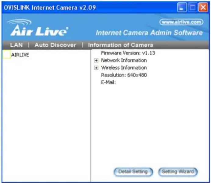 All found camera will appear on the left, select it, then click 'Apply' and discover utility will to input the information of selected IP camera for you; if you click 'Close', the information of selected camera will not be inputted. All found camera will appear on the left, select it, then click 'Apply' and discover utility will to input the information of selected IP camera for you; if you click 'Close', the information of selected camera will not be inputted. |
When a camera is connected, its image will be displayed in the corresponding area in the video viewer window. Repeat steps 1 to 2 to setup more camera, up to 4 cameras can be controlled by a single camera viewer utility.
3.4.2 Select the Camera to View and Control
The status of every camera will be shown in the dashboard (the color bar above the camera's number):

Where:

Blue indicates the video camera is connected,

Red indicates the camera is recording now.

Pink indicates the video camera's information has been set already, but unable to connect to selected camera, or the camera is being stopped or paused, and

Yellow indicates the camera's information is empty.
The length of color bar shows the frame rate of connected camera; when the color bar is longer, the frame rate is higher. A low frame rate may be caused by slow network connection or simple because there's too little motion in the environment that IP camera points to.
If a camera is connected, clicking its number will bring the viewer to single-camera mode
The description of other camera controls on dashboard in single-camera mode will be given below:
| Item | Description |
Camera Setup | Click this button to setup selected camera. Detailed instructions will be given in next section. |
Quad View | Back to 4-camera view mode. |
Reduce View Window | Reduce the size of camera view window (resolution 320 x 240) |
Enlarge View Window | Enlarge the size of camera view window (resolution 620 x 480) |
Rotate View | Flip the captured image upside down (turn 180 degrees), click this button again to return. This function is very useful when camera is installed in a upside-down position. |

| Capture | Save current image as an JPEG image file, you'll hear the sound of camera shutter release when you click this button. The filename of captured file will be named as the time when you hit this button. |
| Stop | Stop getting image from camera. The camera is still working when you click this button, but no images will be transferred to your computer (no data will be sent through network too). Click ‘Play’ button to resume. |
| Pause | Freeze the image displayed in view window, the camera is still working and sending images to your computer when you click this button. Click ‘Play’ button to resume. |
| Record | Begin recording video in AVI format. The filename of recorded video will be named as the time when you hit this button. Click ‘Stop’ button to stop recording. |
| Play | Return to normal state when camera is stopped or paused. |
After all settings are completed, click 'OK' to save settings, or click 'Cancel' to abort and discard changes.
3.5 Advanced Camera Setting
By clicking camera setup button or the number of camera, the advanced setup menu of selected camera will popup:

The description of every setup menu will be given in this section.
Setting
This menu provides basic network and username / password setting of selected camera, as described in section 3.4.1. Please note that when a camera is connected, all settings in this menu will be grayed out and you can not modify any setting.
If you wish to change these settings, please disconnect from the camera first by clicking 'Stop' button in dashboard, until the color bar above the number of camera become pink.
3.5.2 Recording (Scheduled)
If you wish to record video at certain time period, you can use this function to make a scheduled recording list.
Please note that computer must switch on and connected to the IP camera you wish to perform scheduled recording by camera viewer utility.
![Internet Camera Settings Setting Recording Status General About Cycle Recording One-Time Schedules: 2007/06/03 18:28 - 2007/06/03 22:29 2007/08/03 12:28 - 2007/10/03 17:29 New Edit Delete Weekly Schedules: [ Mon Tue ] 18:29:04 - 18:30:04 New Edit Delete OK Cancel](/content/2026/05/1091394/images/862667650d343f2d510ac86a5085c0d9a297284b8b7fcd28591995c3021db734.jpg)
The recording schedule consists two parts: one-time schedule (only executes once), and weekly schedule (executes at specified time and weekday every week). The descriptions of every setting of one time schedule in this menu will be given below:
| Item | Description |
| Cycle Recording(Affects both one-time and weekly schedule) | If the remaining space of hard disk you used to store recorded video is not enough, and this check box is checked, then viewer utility will delete oldest video file automatically to make rooms for new video files.If this check box is unchecked and the disk is full, viewer utility will stop recording, and upcoming recording schedule will not be executed. |
| New | Create a new one-time recording schedule. After you click this button, you'll be prompted to specify the recording schedule: From: Please specify the date and time you wish to start recording for this schedule. Date format is YYYY / MM / DD and time format is HH:MM (24-hour format). You can also use up and down buttonto adjust selected date / time field. However, you can not specify a date / time in the past.To: Please specify the date and time you wish to end recording for this schedule. You can not specify a date / time before the ‘From’ time.Click ‘OK’ to save this schedule or click ‘Cancel’ to discard changes. From: Please specify the date and time you wish to start recording for this schedule. Date format is YYYY / MM / DD and time format is HH:MM (24-hour format). You can also use up and down buttonto adjust selected date / time field. However, you can not specify a date / time in the past.To: Please specify the date and time you wish to end recording for this schedule. You can not specify a date / time before the ‘From’ time.Click ‘OK’ to save this schedule or click ‘Cancel’ to discard changes. |
| Edit | You can select an existing schedule and click ‘Edit’ to change its start / end time. |
| Delete | You can delete an existing schedule. Please select a schedule, then click ‘Delete’. You’ll be prompted to confirm the delete. |
The descriptions of every setting of weekly schedule in this menu will be given below:
| Item | Description |
| New | Create a new weekly recording schedule. After you click this button, you'll be prompted to specify the recording schedule: Sun - Sat: Check the weekday(s) that recording should be executed for this schedule. At least one weekday should be checked.From: Please specify time you wish to start recording for this schedule, time format is HH:MM:SS (24-hour format). You can also use up and down button ↗ to adjust selected time field.Period: Please specify how long this recording schedule should be in HH:MM:SS format.To: Displays when this recording schedule will end ('From' time plus 'Period')Click ‘OK’ to save this schedule or click ‘Cancel’ to discard changes. Sun - Sat: Check the weekday(s) that recording should be executed for this schedule. At least one weekday should be checked.From: Please specify time you wish to start recording for this schedule, time format is HH:MM:SS (24-hour format). You can also use up and down button ↗ to adjust selected time field.Period: Please specify how long this recording schedule should be in HH:MM:SS format.To: Displays when this recording schedule will end ('From' time plus 'Period')Click ‘OK’ to save this schedule or click ‘Cancel’ to discard changes. |
| Edit | You can select an existing schedule and click ‘Edit’ to change its start / end time. |
| Delete | You can delete an existing schedule. Please select a schedule, then click ‘Delete’. You’ll be prompted to confirm the delete. |
3.4.3 Status
This menu shows the statistics of this IP camera since it's connected:

The descriptions of every item in this menu will be given below:
| Item | Description |
| Connected | Shows if this camera is connected. |
| Stream Started At | Shows the total elapsed time since the camera is connected, in second. |
| Video Received (KB) | Shows the total received video data from the camera since the camera is connected, in kilobytes. |
| Audio Received (KB) | Shows the total received audio data from the camera since the camera is connected, in kilobytes. If this camera does not support audio, this value will be ‘0’. |
| Frame Rate (Frame/s) | Shows current frame rate of connected camera (frames per second). |
| Data Rate (KB/s) | Shows current data rate of connected camera (kilobytes per second). |
| Number of Frames | Shows total received frames since the camera is connected. |
| Number of Users | Shows how many users are connected to this camera. |
Click 'OK' or 'Cancel' to exit.
3.4.4 General
In this menu, you can set various parameters of image capturing / video recording, like set the directory used to store image and video file, and set the limit of disk usage.

The descriptions of every item in this menu will be given below:
| Item | Description |
| Snap Shot Directory | Shows the directory (folder) used to store captured image file. If you want to change it, click ‘Change’ and pick a new directory. |
| Record Directory | Shows the directory (folder) used to store recorded video file. If you want to change it, click ‘Change’ and pick a new directory. |
| Free Disk Space | Shows the remaining spaces of the disk. |
| Max Recording Space | You can set the upper limit of the disk space taken by all video files. If you don’t want to run out all hard disk spaces because of video recording, please specify a value smaller than current remaining disk space (refer to ‘Free Disk Space’ above). |
| Used Disk Space | Shows the disk spaces taken by recorded video files. |
| Max Video File Size | Specify the maximum size of every video file. When a recording video file exceeds this limit, viewer utility will open a new file and continue recording on the new file. Large video files will take more time to open, so you can use this function to set the max video file size to a smaller value. The maximum file size can not be greater than 2048 megabytes, due to the restriction of operating system. |
3.4.5 About
This menu provides the version number of viewer utility.
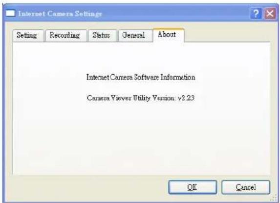
Click 'OK' or 'Cancel' to exit.
3.6 Play Recorded Video
If you need to play recorded video file, please follow the following instructions to select video file to play.
1. Click open file button

on dashboard, and select the video file to play.
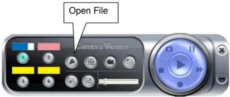
- A new video playback window will appear, you can use mouse to resize the window.

When a video file is opened, you can use these controls to control video playback:

| Play | The video file will play automatically when it loads. If you paused video playback, you can click this button to resume playing. |
| Stop | Stop video playback and close video file. |
| Pause | Pause video playback. Click ‘Play’ to resume. |
| Fast Forward | Click this button to increase video playback speed. The more time you click this button, the speed of video playback will be faster. |
The progress of video playback will also displayed by the progress indicator on the dashboard:

The slide pointer of progress indicator will move right as video plays. You can also use mouse to drag the slide pointer, to control the progress of video playback.
Chapter IV: Appendix
4.1 Specification
Max Resolution: 640 x 480 pixels
Sensor: 300K pixels 1/4" color CMOS sensor
Gain control: Automatic
Exposure: Automatic
White Balance: Automatic
Focal Length: 4.8 mm
Aperture: F=1.8
Image (Video Setting)
Image compression: MPEG4/ MJPEG Image Video
Digital 24-bit Color
Frame rate: 30fps@VGA, QVGA
Video resolution: 160x120, 320x240, 640x480
System Hardware
LAN Connector: One RJ-45 port to connect to 10/100Mbps Ethernet
Wireless: IEEE 802.11b/g (*Wireless Model Only)
LED Indicator: LAN LED (Green), WLAN LED (Amber), Power LED (Blue)
HTTP/Utility
Includes easy-to-use Viewer & Recorder utility
Provides Admin utility & WEB browser Management
View multiple cameras simultaneously - Up to 4 cameras at a time
Manual/Schedule Record, Video Playback/Stop/Forward/Pause
Supports four additional user accounts for viewing camera
Auto sending Snap Shot by E-mail or FTP
Support DDNS and UPnP functions
Supports Windows 2000/XP/Vista
Firmware Upgradeable
EMI & Safety
FCC, CE
4.2 Troubleshooting
If the IP camera is not working properly, before you contact the dealer of purchase for help, please check the troubleshooting list here, this may help you to solve the problem by yourself and therefore saves your valuable time.
| Scenario | Possible Solution |
| I can not connect to IP camera | a. Please confirm the IP address setting of the computer you're using. If they're not in the same subnet, they will not be able to communicate with each other.b. Please make the IP address you used to connect to the IP camera is correct.c. If you forget the IP address of the IP camera, you will have to reset it to factory default value (which is 192.168.2.3) by pressing ‘reset’ button at the bottom of the IP camera. You'll need a pen or pin to be able to press the reset button. Press and hold reset button for 5 seconds, then try to connect to the IP camera with IP address ‘192.168.2.3’ again.d. Please make sure IP camera is correctly powered (the ‘Power’ LED should be on).e. If you're trying to connect to the IP camera from Internet, please make sure the port that IP camera uses (Video and HTTP port, see section 2.3.1) is not blocked by firewall or other software / hardware.f. Contact dealer of purchase for help, if above solutions do not work. |
| Image refreshes very slow | a. Try a higher frame rate setting, if it's not 30.b. Try a lower resolution.c. If you're connecting this camera from Internet, it could be caused by a slow Internet connection, and it's not a problem caused by camera. However, when the network connection is slow, you should use lower frame rate / resolution.d. Adjust the antenna if you're using wireless connection. The antenna should be perpendicular to the ground to get best reception, and the distance between IP camera and computer / wireless access point should not be too far.e. Try to adjust ‘MTU’ setting if you're using PPPoE to connect to Internet. Ask your ISP or network administrator for detailed instruction. |
| IP camera is not responding | a. Is the network cable or wireless connection disconnected? Please check it.b. Unplug the power adapter from wall socket and plug it in again after 10 seconds, then try to connect to the IP camera again.c. If IP camera is correctly powered ('Power' LED is on), but you still can not connect to the camera when you're sure that IP address is correct, please contact dealer of purchase for help). |
| Image is fuzzy | a. Adjust the focus ring on the camera until the image becomes clear.b. Use a soft cloth to clean the lens on the camera. You can use cloth with water, but DO NOT use alcohol or other chemical solution.c. Try to adjust brightness setting.d. If there's any light at the place where IP camera is located, switch it on and see if image looks better. |
| I set the IP camera to send image by Email or FTP, but nothing is received | a. If the image is send by Email, please make sure it's not blocked by any anti-spam mechanism.b. Please make sure you have enough permission for FTP uploading (You can try this by clicking 'Upload a test file' button).c. Make sure the user name and / or password of SMTP server is correct, if your SMTP server requires authentication (You can try this by click 'Send a test Email' button).d. Please check log, if FTP upload or Email sending is failed, it will be logged, and this may give you some clue on how to solve the problem.e. Change the threshold to a more sensitive setting. |
- DECLARATION OF CONFORMITY
- CLAUSE DESCRIPTION
- COPYRIGHT
- FEDERAL COMMUNICATION COMMISSION INTERFERENCE STATEMENT
- FCC CAUTION
- FEDERAL COMMUNICATION COMMISSION (FCC) RADIATION EXPOSURE STATEMENT
- R&TTE COMPLIANCE STATEMENT
- SAFETY
- EU COUNTRIES INTENDED FOR USE
- CONTENTS
- CHAPTER I: FAMILIAR WITH YOUR INTERNET IP CAMERA.... 5
- CHAPTER II: USING WEB MANAGEMENT INTERFACE.... 16
- CHAPTER III: WINDOWS-BASED UTILITY 47
- CHAPTER III: WINDOWS-BASED UTILITY 48
- CHAPTER I: FAMILIAR WITH YOUR INTERNET IP CAMERA
- 1.1 PACKAGE CONTENTS
- 1.2 BASIC INTRODUCTION
- 1.3 PRODUCT HIGHLIGHTS
- 1.4 FAMILIAR WITH KEY COMPONENTS
- FRONT VIEW
- BOTTOM VIEW
- BACK VIEW
- 1.5 DESCRIPTIONS FOR LED INDICATORS
- 1.6 CAMERA INSTALLATION
- 1.7 LOCATE THE IP ADDRESS OF THIS IP CAMERA
- CLICK 'START' -> 'CONTROL PANEL
- DOUBLE-CLICK 'NETWORK CONNECTIONS' ICON
- 1.8 LOG ONTO WEB MANAGEMENT INTERFACE
- OR
- CHAPTER II: USING WEB MANAGEMENT INTERFACE
- 2.1 CAMERA SETTINGS
- 2.2.1 MOTION DETECTION
- 2.2.2 MUTE AUDIO
- 2.2.3 ABOUT
- 2.2 LAN SETTINGS
- 2.2.1 IP ADDRESS
- © LAN
- 2.2.2 PPPOE
- © PPPOE
- 2.2.3 DYNAMIC DNS
- DYNAMIC DNS
- 2.2.4 UPNP
- 2.2.5 LOGINFREE
- © LOGINFREE
- 2.3 WLAN PARAMETERS (FOR WIRELESS MODEL ONLY)
- WIRELESS LAN
- 2.4 AUDIO/VIDEO
- DUAL MODE
- MPEG4
- © MJPEG
- AUDIO
- 2.4.1 DUAL MODE
- 2.4.2 MPEG4
- © MPEG4
- 2.4.3 MJPEG
- MJPEG
- 2.4.4 AUDIO
- 2.5 EMAIL & FTP
- 2.5.1 EMAIL SETTINGS
- 2.5.2 FTP SETTINGS
- FTP CONFIGURATION
- 2.6 MOTION DETECTION
- © MOTION DETECTION
- 2.7 SYSTEM
- 2.7.1 CAMERA INFORMATION
- © CAMERA INFORMATION
- 2.7.2 DATE / TIME SETTING
- DATE / TIME SETTING
- 2.7.3 UTILITIES
- © UTILITIES
- 2.8 STATUS
- STATUS
- 2.9 USERS
- 2.10 LOG
- SYSTEM LOG
- CHAPTER III: WINDOWS-BASED UTILITY
- 3.1 INSTALL WINDOWS-BASED UTILITY
- 3.2 LOCATE CAMERA ON LOCAL NETWORK AND NETWORK SETTING
- 3.3 DETAIL SETTING
- 3.3.1 NETWORK SETTINGS
- 3.3.2 WIRELESS SETTINGS
- 3.3.3 E-MAIL SETTINGS
- 3.3.4 PPPOE SETTINGS
- 3.3.5 FTP SETTINGS
- 3.3.6 DATE / TIME SETTINGS
- 3.3.7 RESOLUTION
- 3.3.8 ADVANCED SETTINGS
- 3.3.9 USERS
- 3.3.10 TOOLS
- 3.3.11 ABOUT
- 3.4 CAMERA VIEWER
- 3.4.1 CONNECTING TO IP CAMERA
- 3.4.2 SELECT THE CAMERA TO VIEW AND CONTROL
- 3.5 ADVANCED CAMERA SETTING
- SETTING
- 3.5.2 RECORDING (SCHEDULED)
- 3.4.3 STATUS
- 3.4.4 GENERAL
- 3.4.5 ABOUT
- 3.6 PLAY RECORDED VIDEO
- CLICK OPEN FILE BUTTON
- CHAPTER IV: APPENDIX
- 4.1 SPECIFICATION
- IMAGE (VIDEO SETTING)
- SYSTEM HARDWARE
- HTTP/UTILITY
- EMI & SAFETY
- 4.2 TROUBLESHOOTING
Brand : AIRLIVE
Model : WL-1200CAM
Category : Webcam