
99-3012G - Car kit Axxess - Free user manual and instructions
Find the device manual for free 99-3012G Axxess in PDF.


| Product Type | Car Installation Kit (Radio Trim Panel with Interface) |
| Brand | AXESS by Metra |
| Model | 99-3012G |
| Compatible Vehicles | Chevrolet Sonic 2012-2016 |
| Color | Painted Gray to Match Factory Finish |
| Radio Provision | ISO DIN with Pocket and ISO DDIN |
| Interface Functions | Retains warning chimes, OnStar/OE Bluetooth, R.A.P., balance/fade, factory AUX-IN; provides NAV outputs (parking brake, reverse, speed sense) and accessory power (12V 10A) |
| Interface Programmability | Micro USB updatable, automatic vehicle programming |
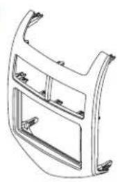
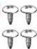
| Kit Components | Radio trim panel (A), radio brackets (B), pocket (C), (4) #8 x 3/8" Phillips screws (D), (4) panel clips (E), Axxess interface with harnesses (F) |
| Tools Required | Panel removal tool, Phillips screwdriver, 9/32" socket wrench, crimping tool/solder gun, small flat blade screwdriver, tape, wire cutter, zip ties |
| Wiring Harness | 16-pin harness with stripped leads, 3012 harness, 12-pin pre-wired ASWC-1 harness, DIN jack |
| Antenna Adapter | 40-EU55 (recommended) |
| Power Requirements | 12V DC, accessory power up to 10A |
| Dimensions (Radio Trim Panel) | Approximately 7" x 4.5" (standard double DIN opening) |
| Weight (Kit) | Approximately 1.5 lbs (0.68 kg) |
| Installation Time | About 1-2 hours (experienced installer) |
| Additional Options | ASWC-1 (steering wheel control retention) and AX-LCD (personalization menu) sold separately |
| Technical Support | Phone: 386-257-1187, Email: techsupport@metra-autosound.com (Mon-Fri 9am-7pm, Sat 10am-7pm, Sun 10am-4pm EST) |
| Warranty | Limited lifetime warranty (by Metra) |
Frequently Asked Questions - 99-3012G Axxess
User questions about 99-3012G Axxess
0 question about this device. Answer the ones you know or ask your own.
Ask a new question about this device
Download the instructions for your Car kit in PDF format for free! Find your manual 99-3012G - Axxess and take your electronic device back in hand. On this page are published all the documents necessary for the use of your device. 99-3012G by Axxess.
USER MANUAL 99-3012G Axxess
natural_image
Interior view of a car dashboard with air vent and blank display panel (no text or symbols visible)Chevrolet Sonic 2012-2016
Visit NetraOnline.com for more detailed information about the product and up-to-date vehicle specific applications
KIT FEATURES
• ISO DIN radio provision with pocket
- ISO DDIN radio provision
- Painted gray to match the factory finish
KIT COMPONENTS
• A) Radio trim panel • B) Radio brackets • C) Pocket • D) (4) #8 x 3/8" Phillips screws • E) (4) Panel clips • F) Axxess interface and wiring harness (not shown)
AB
natural_image
Technical line drawing of a car front panel (no text or symbols)


[Non-Text]
[Non-Text]
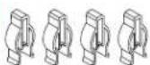
TABLE OF CONTENTS
Dash Disassembly 2
Kit Preparation 2
Kit Assembly
-ISO DIN radio provision with pocket ....3
-ISO DDIN radio provision ....3
Axxess Interface Installation 4
WIRING & ANTENNA CONNECTIONS
Wiring Harness: Visit metraonline.com for audio/video and steering wheel control interface options. Antenna Adapter: 40-EU55
TOOLS REQUIRED
- Panel removal tool • Phillips screwdriver
- 9/32" socket wrench
Attention! With the key out of the ignition, disconnect the negative battery terminal before installing this product. Ensure that all installation connections are secure before cycling the ignition to test this product.
DASH DISASSEMBLY KIT PREPA
- Unclip and remove the panel surrounding the radio/climate controls. (Figure A)
- Remove (4) 9/32" screws securing the radio. Slide the radio out, then unplug and remove the radio. (Figure B)
Continue to kit preparation

natural_image
Diagram of a car air intake manifold showing vent, grille, and side panels (no text or labels)(Figure A) (Figure A)

natural_image
Technical line drawing of a car dashboard with no visible text or symbols(Figure B)
TION
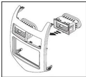
- Unclip the A/C vents from the factory radio/climate control panel.
- Clip the vents into the 99-3012G radio trim panel. (Figure A)
- Attach the (4) panel clips supplied onto the panel.
Continue to kit assembly
natural_image
Technical line drawing of a car air vent assembly with no visible text or symbolsKIT ASSEMBLY
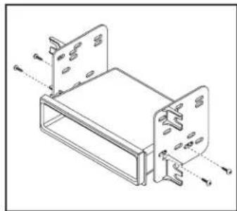
ISO DIN radio provision with pocket
- Secure the radio brackets to the pocket using the (4) #8 x 3/8" screws provided. (Figure A)
- Remove the metal DIN sleeve and trim ring from the aftermarket radio.
- Slide the radio into the bracket/pocket assembly, then secure it using the screws supplied with the radio. (Figure B)
Continue to Axxess Interface Installation
natural_image
Technical line drawing of a mechanical assembly with mounting brackets and fasteners (no text or symbols)(Figure A)

natural_image
Technical line drawing of a mechanical device with ports and mounting brackets (no text or symbols)(Figure B)
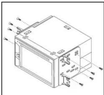
ISO DDIN radio provision
- Attach the radio brackets to the radio using the screws supplied with the radio. (Figure A)
Continue to Axxess Interface Installation
natural_image
Technical line drawing of a device casing with internal components and mounting holes (no text or symbols)(Figure A)
AXXESS INTERFACE INSTALLATION
INTERFACE FEATURES
- Provides accessory power (12-volt 10-amp)
- Maintains the Retained Accessory Power (R.A.P.) feature
- Provides NAV outputs (parking brake, reverse, speed sense)
- Retains warning chimes
- Retains OnStar/OE Bluetooth
- Adjustable volume for chimes and OnStar
- Retains the factory AUX-IN jack
• Pre-wired ASWC-1 harness (ASWC-1 sold separately) - Retains balance and fade
- Micro "B" USB updatable
INTERFACE COMPONENTS
- Axxess interface
• 3012 harness
• 16-pin harness with stripped leads
TABLE OF CONTENTS
Connections to be made 5-6
Installing the Axxess interface 6
Programming the Axxess interface 6-7
Adjusting the Axxess interface....7
Final assembly 7
Troubleshooting....7
TOOLS REQUIRED
- Crimping tool and connectors, or solder gun, solder, and heat shrink
- Small flat blade screwdriver • Tape • Wire cutter • Zip ties
CONNECTIONS TO BE MADE
From the 16-pin harness with stripped leads to the aftermarket radio:
- Connect the Red wire to the accessory wire.
Note: If installing either an ASWC-1 or AX-LCD (both sold separately), connect the (2) Red wires from the 3012 harness as well. - If the aftermarket radio has an illumination wire, connect the Orange/White wire to it.
- If the aftermarket radio has a mute wire, connect the Brown wire to it. If the mute wire is not connected, the radio will turn off when OnStar is activated.
- Connect the Gray wire to the right front positive speaker output.
- Connect the Gray/Black wire to the right front negative speaker output.
- Connect the White wire to the left front positive speaker output.
- Connect the White/Black wire to the left front negative speaker output.
The following (3) wires are only for multimedia/navigation radios that require these wires.
- Connect the Blue/Pink wire to the VSS/speed sense wire.
- Connect the Green/Purple wire to the reverse wire.
- Connect the Light Green wire to the parking brake wire.
- Tape off and disregard the following (5) wires, they will not be used in this application: Blue/White, Purple, Purple/Black, Green, Green/Black
From the 3012 harness to the aftermarket radio:
- Connect the Black wire to the ground wire.
- Connect the Yellow wire to the battery wire.
- If installing either an ASWC-1 or AX-LCD (both sold separately), connect the (2) Red wires to accessory power.
- Cut off and remove the resistors from the Green, Green/Black, Purple, and Purple/Black wires below the heat shrink.
- Connect the Green wire to the left rear positive speaker output.
- Connect the Green/Black wire to the left rear negative speaker output.
- Connect the Purple wire to the right rear positive speaker output.
- Connect the Purple/Black wire to the right rear negative speaker output.
- Ensure the (2) 4-pin Molex connectors are connected together.
- The Black/Yellow wire is used for OnStar level adjustment for models that do not come equipped with steering wheel controls. Refer to the OnStar level Adjustment section for further instructions.
- Tape off and disregard the Pink wire with a red bullet connector, it will not be used in this application.
Continued on the next page
CONNECTIONS TO BE MADE (CONT.)
- If retaining the factory AUX-IN jack is desired, connect the Red and White RCA jacks to the audio AUX-IN jacks from the aftermarket radio.
Note:
a) The jack can only be used if it is a single jack.
b) If the jack has a USB port as well, neither can be retained.
Note: The relay attached to the 3012 harness is only for audible turn signal clicks.
No extra steps are required to retain this feature, so leave the relay as-is.
12-pin pre-wired ASWC-1 harness:
This harness is to be used along with the optional ASWC-1 (sold separately) to retain steering wheel audio controls. If the ASWC-1 is not being used, disregard this harness. If the ASWC-1 will be used, please refer to the ASWC-1 instructions for radio connections and programming. Disregard the harness that comes with the ASWC-1.
DIN jack:
The DIN jack is to be used with the optional AX-LCD (sold separately) to retain the personalization menu.
INSTALLING THE INTERFACE
With the key in the off position:
- Connect the 16-pin harness with stripped leads, and the 3012 harness, into the Axxess interface.
- Locate the factory antenna connector in the dash and complete all necessary connections to the radio. Metra recommends using the proper antenna adapter from Metra.
- If an ASWC-1 (sold separately) will be used, do not connect it until the 99-3012G is programmed and fully functional.
Attention! Do not connect the 3012 harness to the wiring harness in the vehicle just yet.
PROGRAMMING THE INTERFACE
For the steps below, the L.E.D. located inside the interface can only be seen while active. The interface does not need to be opened to see the L.E.D.
- Start the vehicle.
- Connect the 3012 harness to the wiring harness in the vehicle. The L.E.D. will initially be solid Green to indicate the interface is powered.
- After a few seconds the L.E.D. will turn solid Red while the interface automatically programs to the vehicle. The radio will shut off at this point. This process should take 5 to 30 seconds.
Continued on the next page
PROGRAMMING THE INTERFACE (CONT.)
- Once the interface has been programmed the L.E.D. will turn solid Green, then the radio will come back on, indicating programming was successful.
- Test all functions of the installation for proper operation, before reassembling the dash.
- If the interface fails to function, refer to "Troubleshooting", "Resetting the Axxess interface".
Note: The L.E.D. will turn on solid Green for a moment, and then turn off under normal operation after the key has been cycled.
ADJUSTING THE INTERFACE
Chime level adjustment:
- With the vehicle on, turn it off and leave the keys in ignition. Open the driver's door; chimes will be heard.
- Wait 10 seconds, and then with a small flat-blade screwdriver, turn the potentiometer clockwise to raise the chime level; counterclockwise to lower the chime level.
- When the chime is at a desired level, remove the keys from the ignition. This will lock the chime volume at its current level.
OnStar level adjustment:
- Press the OnStar button to activate it.
- While OnStar is speaking, press the VOLUME-UP or VOLUME-DOWN button on the steering wheel to raise or lower the OnStar level.
ADJUSTING THE INTERFACE (CONT.)
- If the vehicle doesn't come equipped with steering wheel controls, locate the Black/Yellow wire on the 3012 harness.
- While OnStar is speaking, tap the Black/Yellow wire to ground. Once the OnStar level is set, it will stay at that level until the Black/Yellow wire is tapped to ground again.
FINAL ASSEMBLY
- Secure the radio assembly to the dash using the factory screws.
- Reassemble the dash in reverse order of disassembly using the 99-3012G radio trim panel to complete the installation.
TROUBLESHOOTING
Resetting the Axxess interface
- The Blue reset button is located inside the Axxess interface, between the two connectors. The button is accessible outside the Axxess interface, no need to open the Axxess interface.
- Press and hold the reset button for two seconds, then let go to reset the Axxess interface.
- Refer to "Programming the Axxess Interface" from this point.
Having difficulties? We're here to help.

our Tech Support line at:
386-257-1187

mail at:
techsupport@metra-autosound.com
Tech Support Hours (Eastern Standard Time)
Monday - Friday: 9:00 AM - 7:00 PM
Saturday: 10:00 AM - 7:00 PM
Sunday: 10:00 AM - 4:00 PM

KNOWLEDGE IS POWER
Enhance your installation and fabrication skills by swelling in the most recognized and respected
mobile electronics school in our industry.
Log onto www.installerinstitute.edu or call
300-672-5171 for more information and take steps toward a better tomorrow.

Metra recommends MECP certified technicians

natural_image
Interior view of a car dashboard with air vent and grille (no visible text or symbols)Chevrolet Sonic 2012-2016
natural_image
Top-down technical illustration of a car air intake bay with no visible text or symbols(Figura A) (Figura A)

natural_image
Top-down technical diagram of a car dashboard with control panels and buttons (no text or labels)(Figura B)
PREPARACIÓN DEL KIT
natural_image
Technical line drawing of a car air intake frame with connector housing (no text or symbols)ENSAMBLE DEL KIT
natural_image
Technical line drawing of a mechanical assembly with two plates and mounting holes (no text or symbols)(Figura A)
natural_image
Technical line drawing of a device casing with internal components and directional arrows indicating flow (no text or symbols)(Figura A)

natural_image
Technical line drawing of a device casing with internal components and mounting holes (no text or symbols)(Figura B)
Monday - Friday: 9:00 AM - 7:00 PM
Saturday: 10:00 AM - 7:00 PM
Sunday: 10:00 AM - 4:00 PM

KNOWLEDGE IS POWER
Enhance your installation and fabrication skills to enrolling in the most recognized and respected
mobile electronics school in our industry.
Log onto www.installerinstitute.edu or call 288 670 5771 (for more information and tel
386-672-5771 for more information and take steps toward a better tomorrow.


- Chevrolet Sonic 2012-2016
- KIT FEATURES
- KIT COMPONENTS
- TABLE OF CONTENTS
- WIRING & ANTENNA CONNECTIONS
- TOOLS REQUIRED
- DASH DISASSEMBLY KIT PREPA
- TION
- KIT ASSEMBLY
- ISO DIN radio provision with pocket
- ISO DDIN radio provision
- AXXESS INTERFACE INSTALLATION
- INTERFACE FEATURES
- INTERFACE COMPONENTS
- CONNECTIONS TO BE MADE
- From the 16-pin harness with stripped leads to the aftermarket radio:
- From the 3012 harness to the aftermarket radio:
- CONNECTIONS TO BE MADE (CONT.)
- Note:
- 12-pin pre-wired ASWC-1 harness:
- DIN jack:
- INSTALLING THE INTERFACE
- With the key in the off position:
- PROGRAMMING THE INTERFACE
- PROGRAMMING THE INTERFACE (CONT.)
- ADJUSTING THE INTERFACE
- Chime level adjustment:
- OnStar level adjustment:
- ADJUSTING THE INTERFACE (CONT.)
- FINAL ASSEMBLY
- TROUBLESHOOTING
- Resetting the Axxess interface
- Tech Support Hours (Eastern Standard Time)
- PREPARACIÓN DEL KIT
- ENSAMBLE DEL KIT
Brand : Axxess
Model : 99-3012G
Category : Car kit