
DS20-55BL - Drill Stalco - Free user manual and instructions
Find the device manual for free DS20-55BL Stalco in PDF.


| Type | Cordless drill/driver |
| Model | DS20-55BL |
| Rated voltage | 20 V max (18 V nominal) |
| No-load speed (1st gear) | 0-420 min⁻¹ |
| No-load speed (2nd gear) | 0-1400 min⁻¹ |
| Max torque (soft/hard) | 35 / 55 Nm |
| Chuck type | Keyless chuck |
| Chuck capacity | 2-13 mm |
| Drilling capacity (steel) | 13 mm |
| Drilling capacity (wood) | 40 mm |
| Weight | 1.32 kg |
| Battery type | Li-Ion (S-VOLT series only) |
| Battery capacity | 2 Ah |
| Charging time | 60 min (depending on charger) |
| Sound pressure level | 76 dB(A) |
| Sound power level | 87 dB(A) |
| Vibration level (drilling) | 2.3 m/s² |
| Motor type | Brushless motor |
| Speed control | Variable speed trigger (stepless) |
| Reverse switch | Yes, clockwise/counterclockwise |
| Torque adjustment | 21+1 position torque regulator |
| Additional handle | Yes (optional extra) |
| LED work light | Yes, automatic |
| Belt clip | Yes (optional extra) |
| Depth stop | Yes (optional extra) |
| Battery charge indicator | Yes, push-button with LEDs |
| Break rundown | Yes, stops spindle immediately when trigger released |
Frequently Asked Questions - DS20-55BL Stalco
User questions about DS20-55BL Stalco
0 question about this device. Answer the ones you know or ask your own.
Ask a new question about this device
Download the instructions for your Drill in PDF format for free! Find your manual DS20-55BL - Stalco and take your electronic device back in hand. On this page are published all the documents necessary for the use of your device. DS20-55BL by Stalco.
USER MANUAL DS20-55BL Stalco
natural_image
Exterior view of a STALC® S-VOLT battery with a drill press and two battery modules (no text or symbols on the main body)
20V MAX.

1: 0-420 MIN ^-1
II: 0-1400 MIN ^-1

35-55 NM

2·13 MM

LEWO/PRAWO
CE


DANE TECHNICZNE ELEKTRONARZĘDZIA
BEZPIECZEŃSTWO W MIEJSCU PRACY
natural_image
Line drawing of a portable electronic device with a 18-degree cable and power plug (no text or symbols)

natural_image
Line drawing of a portable electrical charger with a 18-inch cable (no text or symbols)
PL
PL
EN


natural_image
Illustration of a hand using a screwdriver to install a wall-mounted component, with no visible text or symbols.12
PL
EN
Mafewy Mauoig Specialista ds.
natural_image
Exterior view of a STALC-brushless electric drill with battery pack (no signage)
20V MAX.

1:0-420 MIN ^-1
II: 0-1400 MIN ^-1

35-55 NM

2·13 MM

LEFT/RIGHT
CE


POWER TOOL SPECIFICATIONS
| Cordless drill / screwdriver S-97310, S-97312 | DS20-55BL |
| Rated voltage [V] | 20* |
| No-load speed (first gear "L" / second gear "H") [min-1] | 0-420 / 0-1400 |
| Max. torque (soft / hard) [Nm] | 35 / 55 |
| Battery type | Li-Ion** |
| Battery charging time [min] | 60*** |
| Battery capacity [Ah] | 2 |
| Chuck tightening range [mm] | 2-13 |
| Drilling output | |
| - concrete [mm] | - |
| - steel [mm] | 13 |
| - dwood [mm] | 40 |
| Weight [kg] | 1,32 |
| Sound pressure L_PA K=5dB(A) [dB(A)] | 76 |
| Acoustic power L_WA K=5dB(A) [dB(A)] | 87 |
| Vibration a_h,D K=1.5m/s2 [m/s2] | 2.3 |
| *Maximum initial battery voltage (measured without workload) is 20 Volts. Nominal voltage is 18 Volts. **S-VOLT series batteries only are suitable to the power tool *** Battery charging time depends on the type of charger used. | |

Noise information
Always wear ear protection if the sound pressure exceed 85 dB(A).

WARNING - To reduce the risk of injury, user must read instruction manual!
GENERAL SAFETY RULES

WARNING! Read all safety warnings, instructions, illustrations and specifications provided with this power tool. Failure to follow the warnings and instructions may result in electric shock, fire and / or serious injury. Save all warnings and instructions for future reference. The term "power tool" in the warnings refers to your mains-operated (corded) power tool or battery operated (cordless) power tool.
WORK AREA SAFETY
- Keep work area clean and well lit. Cluttered or dark areas invite accidents.
- Do not operate power tools in explosive atmospheres, such as in the presence of flammable liquids, gases or dust. Power tools create sparks which may ignite the dust or fumes.
- Keep children and bystanders away while operating a power tool. Distractions can cause you to lose control.
ELECTRICAL SAFETY
- Power tool plugs must match the outlet. Never modify the plug in any way. Do not use any adapter plugs with earthed (grounded) power tools. Unmodified plugs and matching outlets will reduce risk of electric shock.
- Avoid body contact with earthed or grounded surfaces, such as pipes, radiators, ranges and refrigerators. There is an increased risk of electric shock if your body is earthed or grounded.
-
Do not expose power tools to rain or wet conditions. Water entering a power tool will increase the risk of electric shock.
-
Do not abuse the cord. Never use the cord for carrying, pulling or unplugging the power tool. Keep cord away from heat, oil, sharp edges or moving parts. Damaged or entangled cords increase the risk of electric shock.
- When operating a power tool outdoors, use an extension cord suitable for outdoor use. Use of a cord suitable for outdoor use reduces the risk of electric shock.
- If operating a power tool in a damp location is unavoidable, use a residual current device (RCD) protected supply. Use of an RCD reduces the risk of electric shock. NOTE! The term "residual current device (RCD)" may be replaced by the term "ground fault circuit interrupter (GFCI)" or "earth leakage circuit breaker (ELCB)".
- Warning! Never touch the exposed metal surfaces on gearbox, shield, and so on because touching metal surfaces will be interfered with the electromagnetic wave, thus causing potential injury or accidents.
PERSONAL SAFETY
- Stay alert, watch what you are doing and use common sense when operating a power tool. Do not use a power tool while you are tired or under the influence of drugs, alcohol or medication. A moment of inattention while operating power tools may result in serious personal injury.
- Use personal protective equipment. Always wear eye protection. Protective equipment such as dust mask, non-skid safety shoes, hard hat, or hearing protection used for appropriate conditions will reduce personal injuries.
- Prevent unintentional starting. Ensure the switch is in the off position before connecting to power source and / or battery pack, picking up or carrying the tool. Carrying power tools with your finger on the switch or energising power tools that have the switch on invites accidents.
- Remove any adjusting key or wrench before turning the power tool on. A wrench or a key left attached to a rotating part of the power tool may result in personal injury.
- Do not overreach. Keep proper footing and balance at all times. This enables better control of the power tool in unexpected situations.
- Dress properly. Do not wear loose clothing or jewellery. Keep your hair, clothing and gloves away from moving parts. Loose clothes, jewellery or long hair can be caught in moving parts.
- If devices are provided for the connection of dust extraction and collection facilities, ensure these are connected and properly used. Use of dust collection can reduce dust-related hazards.
- Do not let familiarity gained from frequent use of tools allow you to become complacent and ignore tool safety principles. A careless action can cause severe injury within a fraction of a second.
- Warning! Power tools can produce an electromagnetic field during operation. This field may under some circumstances interfere with active or passive medical implants. To reduce the risk of serious or fatal injury, we recommend persons with medical implants to consult their physician and the medical implant manufacturer before operating this power tool.
POWER TOOL USE AND CARE
- The persons with lowered psychophysical or mental aptitudes as well as children can not operate the power tool, if they are not supervised or instructed about use of the power tool by a person responsible for their safety.
- Do not force the power tool. Use the correct power tool for your application. The correct power tool will do the job better and safer at the rate for which it was designed.
- Do not use the power tool if the switch does not turn it on and off. Any power tool that cannot be controlled with the switch is dangerous and must be repaired.
- Disconnect the plug from the power source and / or the battery pack from the power tool before making any adjustments, changing accessories, or storing power tools. Such preventive safety measures reduce the risk of starting the power tool accidentally.
- Store idle power tools out of the reach of children and do not allow persons unfamiliar with the power tool or these instructions to operate the power tool. Power tools are dangerous in the hands of untrained users.
- Maintain power tools. Check for misalignment or binding of moving parts, breakage of parts and any other condition that may affect the power tool's operation. If damaged, have the power tool repaired before use. Many accidents are caused by poorly maintained power tools.
- Keep cutting tools sharp and clean. Properly maintained cutting tools with sharp cutting edges are less likely to bind and are easier to control.
- Use the power tool, accessories and tool bits to be performed. Use of the power tool for operations different from those intended could result in a hazardous situation.
- Keep handles and grasping surfaces dry, clean and free from oil and grease. Slippery handles and grasping surfaces do not allow for safe handling and control of the tool in unexpected situations.
- Note that when you operate a power tool, please hold the auxiliary handle correctly, which is helpful when controlling the power tool. Therefore, proper holding can reduce the risk of accidents or injuries.
BATTERY TOOL USE AND CARE
- Recharge only with the charger specified by the manufacturer. A charger that is suitable for one type of battery pack may create a risk of fire when used with another battery pack.
- Use power tools only with specifically designated battery packs. Use of any other battery packs may create a risk of injury and fire.
- When battery pack is not in use, keep it away from other metal objects, like paper clips, coins, keys, nails, screws or other small metal objects, that can make a connection from one terminal to another. Shorting the battery terminals together may cause burns or a fire.
- Under abusive conditions, liquid may be ejected from the battery; avoid contact. If contact accidentally occurs, flush with water. If liquid contacts eyes, additionally seek medical help. Liquid ejected from the battery may cause irritation or burns.
- Avoid unintentional switching on. Ensure the on / off switch is in the off position before inserting battery pack. Carrying the power tool with your finger on the on / off switch or inserting the battery pack into power tools that have the switch in accidents.
- Do not open the battery. Danger of circuit.
-
In case of damage and improper use of the battery, vapors may be emitted. Provide for fresh air and seek medical help in case of complaints. The vapors can irritate the respiratory system.
-
When the battery is defective, liquid can escape and come into contact with adjacent components. Check any parts concerned. Clean such parts or replace them, if required.
- Protect the battery against heat, e.g., also against continuous sun irradiation and fire. There is danger of explosion.

WARNING! Read all safety warnings and all instructions.
- Protect the battery charger from rain and moisture. The penetration of water in a battery charger increases the risk of electric shock.
- Do not charge other batteries. The battery charger is suitable only for charging lithium ion batteries within the listed voltage range. Otherwise there is danger of fire and explosion.
- Keep the battery charger clean. Contamination may cause the danger of electric shock.
- Check the battery charger, cable and plug each time before using. Do not use the battery charger when defects are detected. Do not open the battery charger yourself and have it repaired only by qualified personnel using original spare parts. Damaged battery chargers, cables and plugs increase the risk of electric shock.
- Do not operate the battery charger on easily inflammable surfaces (e.g., paper, textiles, etc.) or in combustible environments. There is danger of fire due to the heating of the battery charger during charging.
SERVICE
- Have your power tool serviced by a qualified repair person using only identical replacement parts. This will ensure that the safety of the power tool is maintained.
- Follow instruction for lubricating and changing accessories.
- Wear ear protectors when impact drilling. Exposure to noise can cause hearing loss.
NOTE: The above warning applies only to impact drills and may be omitted for drills other than impact drills. - Use auxiliary handle(s), if supplied with the tool. Loss of control can cause personal injury.
- Hold power tool by insulated gripping surfaces, when performing an operation where the cutting accessory may contact hidden wiring or its own cord. Cutting accessory contacting a "live" wire may make exposed metal parts of the power tool "live" and could give the operator an electric shock.
SAFETY GUIDELINES DURING POWER TOOL OPERATION
- The workpiece shall be fastened. Fixed devices or vice shall be used to fasten the workpiece, which will be more secure than holding the workpiece with your hands.
- Considering that asbestos may cause cancer, asbestos - containing materials shall not be processed.
- The power tool could be put down only after the parts of power tool is completely static. Accessory on the power tool might be clamped during work, which may make it difficult for you to control the power tool.
- Appropriate detector shall be used to find the location of hidden power wires. Or you should obtain relevant information from local power supply unit. Drilling electric wires will cause fire and electric shock. Damaged gas pipe will cause exploration. If
water pipes are punctured, damage will be caused to property.
- In case a accessory installed on the power tool is clamped, you shall shut down the power tool and stay calm. At that time, the power tool will produce extremely high reactive torque thus resulting in return stroke. The accessory installed on the power tool are likely to be clamped, for example: hypercharge of power tool or skewing of accessory installed on the power tool during work.
- If hidden electric wires or power lines of the power tool itself might be cut off during work, you must hold the insulated handle to operate the power tool. When the power tool is in touch with a charged line, the metal parts on the power tool will conduct electricity and may cause the operator to get an electric shock.
- During work, you must tightly hold the power tool and ensure you stand firmly. You should hold the power tool with your hands.
- When operating and using the power tool, you can only hold switch position of the main handle rather than other parts.
- Avoid stopping an power tool motor when loaded.
- Never remove any chips or fragments with your power tool's motor running.
- Use accessories without defects - it will make working with the power tool easier.
- The modification of the drill bits design and the use of removable orifices and accessories not envisaged for this power tool is strictly forbidden.
- Do not apply excessive pressure when operating the power tool - it can jam the drill bit and overload the engine.
- Do not allow drill bits to jam in the material processed. If this occurs, do not try to release them by means of the power tool engine. This can put the power tool out of order.
- Striking out drill bits jammed in the material processed with a hammer or other objects is strictly forbidden - metal fragments can hurt both the operator and the people nearby.
- Avoid overheating your power tool, when using it for a long time.
SYMBOLS USED IN THE MANUAL
Following symbols are used in the operation manual, please remember their meanings. Correct interpretation of the symbols will allow correct and safe use of the power tool.

Brushless motor.

Read all safety regulations and instructions.

Wear safety goggles.

Wear ear protectors.

Wear a dust mask.

Wear protective gloves.

Do not heat the battery above 45^ C. Protect from prolonged exposure to direct sunlight.

Do not dispose of the battery in a domestic waste container.

Do not dispose of the battery in the fire.

Protect the battery from the rain.

Battery charging time.

Movement direction.


Rotation direction.

Locked.

Unlocked.

Prohibited.

"Screwing" mode.

"Drilling" mode.

"Impact drilling" mode.

Drill tiles in the impactless drilling operation mode only.

A sign certifying that the product complies with essential requirements of the EU directives and harmonized EU standards.

Attention. Important.

Useful information.

Stepless speed control.
Do not dispose of the power tool in a domestic waste container.
POWER TOOL DESIGNATION
The power tool has been designed for hole drilling in wood, plastic and metal, as well as for screwing in and loosening of threaded fastening elements (screws, bolts, etc.).
POWER TOOL COMPONENTS


natural_image
Line drawing of a portable electronic device with attached wires and a 18-degree angle label (no text or symbols on the device itself)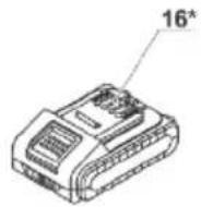

PL
EN
- Additional handle *
- Depth stop *
- Keyless chuck
- LED lamp
- Battery lock *
- Control button of the state of battery charge *
- Indicators of the state of battery charge *
- Clamping screw *
- Step speed selector switch
- Ventilation slots
- Function switch
- Torque regulator
- Strap *
- Reverse switch
- On / off switch
- Battery *
- Belt clip *
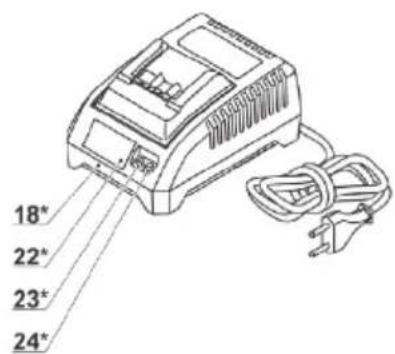
- Charger *
- Screwdriver bit *
* Optional extra
Not all of the accessories illustrated or described are included as standard delivery.
Power tool set S-97312 does not include battery and charger.
INSTALLATION AND REGULATION OF POWER TOOL ELEMENTS
Before execution of any procedures, centre the reverse switch 14.

Do not draw up the fastening ele- ments too tight to avoid damaging the thread.

Mounting / dismounting / setting-up of some elements is the same for all power tool models, in this case specific models are not indicated in the illustration.
MOUNTING / REPLACEMENT OF ACCESSORIES (SEE FIG. 1)

During prolonged use, the drill bit may reach high temperature; use protective gloves to remove it.
- Open the jaws of the keyless chuck 3, rotating its front part as shown in fig. 1.
- Mount /replace the accessory.
- Tighten the keyless chuck 3 without skewing the accessory as it is shown in fig. 1.

1
PL
EN
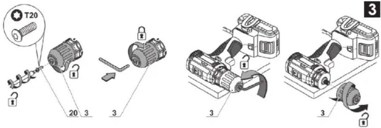
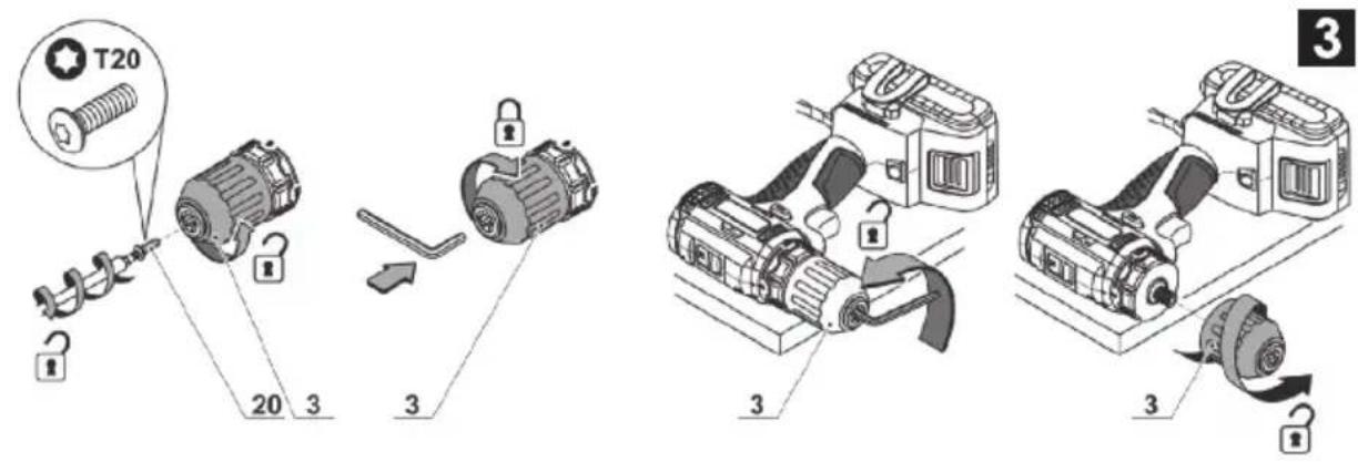
MOUNTING / DISMOUNTING OF THE KEYLESS CHUCK (SEE FIG. 2,3)
- To mount the keyless chuck 3, carry out the operations in consecutive stages as it is shown in fig. 2-3.
- To dismount the keyless chuck 3, carry out the operations in consecutive stages as it is shown in fig. 2-3.

Attention: keep in mind that in the process of mounting / dismounting of the keyless chuck 3 the screw 20 has a left-hand thread.

PL
EN
SCREWDRIVER BIT / MAGNETIC HOLDER (SEE FIG. 4)
For short screwdriver bits use the magnetic holder 21 for their reliable fixing (see fig. 4). A magnetic holder 21 is not needed for extended screw-driver bits 19 (specially purposed for screwdrivers).

4
CHARGING PROCEDURE OF THE POWER TOOL BATTERY
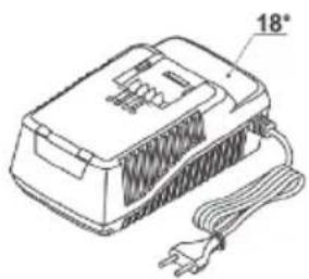
The power tool is supplied with a partially charged battery 16. Before the first use, the battery 16 must be fully charged.
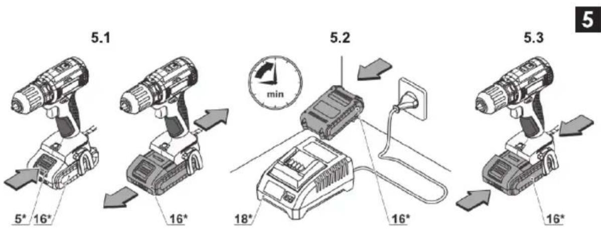
CHARGING PROCESS (SEE FIG. 5)
• Centre the reverse switch 14.
- Press the battery lock 5 and remove the battery 16 (see fig. 5.1).
- Connect the charger 18 to the power supply.
- Insert battery 16 into charger 18 (see fig. 5.2).
- Disconnect the charger 18 from power supply aftercharging.
- Remove the battery 16 from the charger 18 and mount battery 16 in the power tool (see fig. 5.3).
CHARGER INDICATORS (SEE FIG. 6-7)
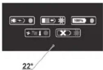
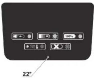
Charger indicators 23 and 24 inform of the battery 16 charging process. Signals of the indicators 23 and 24 are shown on the label 22 (see fig. 12-14).
- Fig. 6.1, 7.1 - (the green indicator 24 is on, the battery 16 is not inserted in the charger 18) - the charger 18 is connected to the power network (readyfor charging).
- Fig. 6.2, 7.2 - (the green indicator 24 is blinking, the battery 16 is inserted in the charger 18) - the battery 16 is being charged.
- Fig. 6.3, 7.3 - (the green indicator 24 is on, the battery 16 is inserted in the charger 18) - the battery 16 is fully charged.
- Fig. 6.4, 7.4 - (the red indicator 23 is on, the battery 16 is inserted in the charger 18) - the charging process of the battery 16 is terminated due to inappropriate temperature. When the temperature conditions are normal, the process of charging will resume.
- Fig. 6.5, 7.5 - (the red indicator 23 is blink-ing, the battery 16 is inserted in the charger 18) - the charging process of the battery 16 is terminated because of its failure. Replace the faulty battery 16, its further use is prohibited.

In the process of charging the battery 16 and the charger 18 become hot, it is a normal process.
PL
EN
S-97391
6.1

6.2
6.3

6.4

6.5

6

S-97393
7.1

7.2
7.3
7.4

7.5

7
SWITCHING THE POWER TOOL ON / OFF
Make sure that the reverse switch 14 is not centred, this blocks on / off switch 15.
Switching on:
Press on / off switch 15.
Switching off:
Release the on/off switch 15.
DESIGN FEATURES OF THE POWER TOOL
BATTERY
The battery 16 is protected by the safety system against deep discharge. In case of complete discharge, the power tool is automatically switched off. Attention: do not try to switch on the power tool when the protection system is activated the battery 16 can be damaged.
TEMPERATURE PROTECTION
The temperature protection system enables to auto- matically deactivate the power tool in case of excess load. The system guarantees protection of the power tool from damage in case of noncompliance with the operation conditions.
INDICATORS OF THE STATE OF BATTERY CHARGE (SEE FIG. 8)
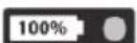
With the push of the button 6 the indicators 7 show the state of charge of the battery 16 (see fig. 8).

S-97383

S-97381
LED LAMP
When the on / off switch 15 is pushed, the LED lamp 4 is automatically switched on that allows to carry out works in low light conditions.
STEPLESS SPEED ADJUSTMENT

Speed is controlled from 0 to maximum by pressing force of on / off switch 15. Weak pressing results in low revolutions, which enable a smooth power tool switch-on.
STEP SPEED SELECTOR SWITCH

Attention: one can only change the revolutions per minute range after the engine fully stops.
In order to put in the "L" gear, move the switch 9 back. This mode is used for the fastening of screws or for large diameter hole drilling.
In order to choose the "H" gear, move the switch 9 forward. This mode is used for speed drilling of small diameter holes.
CHANGING THE ROTATIONAL DIRECTIONS (SEE FIG. 9)


Change the direction of rotation only after a full stop of the motor, acting otherwise may cause damage to the power tool.
Clockwise rotation (drilling, fastening of screws)
move the reverse switch 14 to the left as it is shown in fig. 9.1.
Counter clockwise rotation (unscrewing the screws)
move the reverse switch 14 to the right as it is shown in fig. 9.2.


If the on / off switch 15 is not pressed, the spindle of the power tool is locked this enables to use the power tool as an ordinary screwdriver (for example it can be used to tighten manually screws or bolts, if the battery is low).
BREAK RUNDOWN
Break rundown stops the spindle of the power tool immediately after the power tool is turned off. This helps to avoid an excessive tightening of the bolts and screws and prevents work pieces, screwdriver bits and slots of fastening elements from being damaged.
BRUSHLESS MOTOR
Power tool equipped with a brushless motor that provides the following advantages (compared to the power tool having a brush motor):
- high reliability due to the lack of wearing parts (carbon brushes, commutator);
• increased operating time on a single charge; - compact design and light weight.
- Grease the drill bit regularly when drilling holes in metals (except drilling non-ferrous metals and their alloys).
- When drilling hard metals, apply more force to the power tool and lower the rotation speed.
- When drilling large diameter holes in metal, first drill a hole with a smaller diameter and ream it till the necessary diameter (see fig. 10.1).
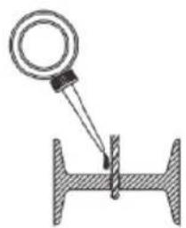
- In order to avoid splitting of the surface at an exit point of a drill bit when drilling holes in wood, follow the instructions shown in figure 10.2.
- In order to decrease dust production when drilling holes in walls and ceilings, take actions indicated in fig. 11.
- When drilling holes in glazed ceramic tiles, in order to improve the drill centering accuracy and to save the glaze from damage, apply adhesive tape to the presumed hole center and drill after that (see fig. 12). Start drilling at lower speed increasing it as the hole deepens.
10.1
10.2
10
natural_image
Diagram of a mechanical setup with a magnifying glass and threaded rod (no text or symbols)

natural_image
Diagram of a mechanical joint or cutting tool with a magnified inset showing the tip (no text or symbols present)

natural_image
Diagram of a cutting tool with a twist drill bit, shown in a mechanical setup (no text or labels)

natural_image
Illustration of a hand using a power drill to install a wall-mounted component, with no visible text or symbols.12
SCREWING THE SCREWS (SEE FIG. 13)
- To make fastening of screws easier and in order to prevent cracking of the work pieces, first drill a hole with a diameter equal to 2/3 of a diameter of the screw.
- If you are connecting work pieces with the help of screws, in order to achieve durable joint without getting cracks, fracturing or layering, take actions shown in figure 13.

POWER TOOL MAINTENANCE / PREVENTION
Before execution of any procedures, centre the re-verse switch 14.
BATTERY MAINTENANCE INSTRUCTION
- Charge timely before the battery 16 is completely exhausted. Stop operation in low power and charge it immediately.
- Do not overcharge when the battery 16 is full, otherwise it will shorten the life time.
- Charge battery 16 in the room temperature of 10^ to 40^ .
- Charge battery 16 every 6 months without operation for a long time.
- Replace worn out batteries in time. Decline of production or a significantly shorter runtime of the power tool after charging indicates aging of the battery 16 and the need for replacement. It should be taken into account that the battery 16 may discharge faster if the works take place in the temperature below 0°C.
- In case of long time storage without use, it is recommended to store the battery 16 at room temperature, it should be charged to 50%.
CLEANING OF THE POWER TOOL
An indispensable condition for a safe long-term exploitation of the power tool is to keep it clean. Regularly flush the power tool with compressed air thought the ventilation slots 10.
WARRANTY
We guarantee the products in accordance with statutory/country-specific regulations (proof of purchase by invoice or delivery note). Damage attributable to normal wear and tear, overload or improper handling will be excluded from the guarantee. In case of a claim, please send the machine, completely assembled, to your dealer or the Central Warranty Service STALCO. Terms and conditions are included in the Warranty Card attached.
TRANSPORT
- Categorically not to drop any mechanical impact on the packaging during transport.
- When unloading / loading is not allowed to use any kind of technology that works on the principle of clamping packaging.
LI-ION BATTERIES
The contained Li-Ion batteries are subject to the Dangerous Goods Legislation requirements. The user can transport the batteries by road without further requirements. When being transported by third parties (e.g.: air transport or forwarding agency), special requirements on packaging and labelling must be observed. For preparation of the item being shipped, consulting an expert for hazardous material is required. Dispatch batteries only when the housing is undamaged. Tape or mask off open contacts and pack up the battery in such a manner that it cannot move around in the packaging. Please also observe possibly more detailed national regulations.
ENVIRONMENTAL PROTECTION

Recycle raw materials instead of disposing as waste.
Power product containers disposed of aging should be wasted for waste environment and electrical equipment and batteries contain hazardous substances which, if released into the environment, penetrate groundwater, soil and air, posing a threat to living organisms and people. Recycle raw materials instead of throwing them away. Used devices and batteries contain valuable recyclable materials that should be sent for reuse so as not to harm the natural environment and human health through uncontrolled waste disposal. Used devices and batteries should be disposed of using special waste collection systems. For recycling information, please contact your local authority or retailer.
PL
EN

PL
EN
PART LIST
PL
EN
No DESCRIPTION QTY
1 Countersunk head screw\M6x27
2 Drill chuck 1
3 Torque sleeve 1
4 Gear box assy.
4-1 Torque adjusting body
4-2 Spring
4-3 Washer ∅28x∅39x1
4-4 Pin ∅4.0x10.4 6
4-5 Spindle 1
4-6 Ball bearing 1
4-7 Felt ring ∅17x∅9x3 2
4-8 Torque sleeve plate
4-9 Front gear housing
4-10 Friction bearing
4-11 Washer ∅10.5x∅21x0.5
4-12 Circlip for shaft ∅10
4-13 Spindle lock ring
4-14 Pin ∅3.6x5 3
4-15 Third ring gear
4-16 Third sun gear
4-17 Third planet gear 3
4-18 Washer ∅39x∅14.5x0.8
4-19 Washer ∅30.3x∅37.5x1.5
4-20 Second sun gear
4-21 Second planet gear 3
4-22 Second ring gear
4-23 Speed change wire
4-24 First sun gear
4-25 First planet gear 3
4-26 First ring gear
4-27 Washer ∅12x∅33.5x0.5
4-28 Rear gear housing
5 Motor body assy.
5-1 Pinion 1
5-2 Stator 1
5-3 Armature
6 Speed trigger
7 Spring 1
8 Housing cover 1
13 Housing
9 Rubber pin ∅4.0x3.5 2
10 Tapping screw ST3x12 8
11 Lamp cover
12 F/R lever 1
14 Switch
15 PCB assy.
16 Housing contact plate holder 7
17 Nut 2
18 Belt buckle 1
19 Pan head screw M3x8
20 Battery pack assy. 2
21 Charger assy 1
DECLARATION OF CONFORMITY
We
STALCO
declare under our sole responsibility that the product:
CORDLESS DRILL
DS20-55BL
Catalog no.: S-97310 / S-97312
Type: CT21091HX
CT21091 HX
BMC
to which this declaration is in conformity with following directives:
Machinery Directive 2006/42/EC
Electromagnetic Compatibility Directive 2014/30/EU
RoHS Directive 2011/65/EU
Standards and technical specifications referred to:
EN 62841-1:2015
EN 62841-2-1:2018+A11:2019
EN 55014-1:2017+A11
EN 55014-2:2015
Responsible for documentation:
STALCO
Malewu Mowor Specialista ds.
- BEZPIECZEŃSTWO W MIEJSCU PRACY
- Noise information
- GENERAL SAFETY RULES
- WORK AREA SAFETY
- ELECTRICAL SAFETY
- PERSONAL SAFETY
- POWER TOOL USE AND CARE
- BATTERY TOOL USE AND CARE
- WARNING! Read all safety warnings and all instructions.
- SERVICE
- SAFETY GUIDELINES DURING POWER TOOL OPERATION
- SYMBOLS USED IN THE MANUAL
- POWER TOOL DESIGNATION
- POWER TOOL COMPONENTS
- INSTALLATION AND REGULATION OF POWER TOOL ELEMENTS
- MOUNTING / REPLACEMENT OF ACCESSORIES (SEE FIG. 1)
- MOUNTING / DISMOUNTING OF THE KEYLESS CHUCK (SEE FIG. 2,3)
- SCREWDRIVER BIT / MAGNETIC HOLDER (SEE FIG. 4)
- CHARGING PROCEDURE OF THE POWER TOOL BATTERY
- CHARGING PROCESS (SEE FIG. 5)
- CHARGER INDICATORS (SEE FIG. 6-7)
- SWITCHING THE POWER TOOL ON / OFF
- DESIGN FEATURES OF THE POWER TOOL
- BATTERY
- TEMPERATURE PROTECTION
- INDICATORS OF THE STATE OF BATTERY CHARGE (SEE FIG. 8)
- LED LAMP
- STEPLESS SPEED ADJUSTMENT
- STEP SPEED SELECTOR SWITCH
- CHANGING THE ROTATIONAL DIRECTIONS (SEE FIG. 9)
- Clockwise rotation (drilling, fastening of screws)
- Counter clockwise rotation (unscrewing the screws)
- BREAK RUNDOWN
- BRUSHLESS MOTOR
- SCREWING THE SCREWS (SEE FIG. 13)
- POWER TOOL MAINTENANCE / PREVENTION
- BATTERY MAINTENANCE INSTRUCTION
- CLEANING OF THE POWER TOOL
- WARRANTY
- TRANSPORT
- LI-ION BATTERIES
- ENVIRONMENTAL PROTECTION
- Recycle raw materials instead of disposing as waste.
- PART LIST
- DECLARATION OF CONFORMITY
Brand : Stalco
Model : DS20-55BL
Category : Drill