
IHD-200PR - Adapter / Network Card Planet - Free user manual and instructions
Find the device manual for free IHD-200PR Planet in PDF.


| Product Type | HDMI over IP Receiver with PoE |
| Model | IHD-200PR |
| Dimensions (W x D x H) | 130 x 96 x 25 mm |
| Weight | 492 g |
| Power Supply | 9-12V DC, 1.5A or PoE (IEEE 802.3af) |
| Power Consumption | 13.5W per unit |
| Network Interface | 1 x RJ-45 (10/100/1000Base-T Ethernet) |
| Video Interface | HDMI Type A |
| Maximum Video Resolution | Full HD 1920 x 1080, WUXGA 1920 x 1200 @ 60 Hz |
| HDCP Support | Yes, HDCP-compliant |
| Audio Support | HDMI with 2ch audio (dts) |
| Maximum Transmission Distance | 100 meters point-to-point or multicast |
| Channel Selection | 16 channels via rotary DIP switch |
| Casting Modes | Unicast, Multicast |
| Video Wall Support | Up to 8x8 screens |
| EDID Management | EDID copy function |
| Management | Web UI, button controls, DIP switches |
| Cabling | Cat. 5/5e/6 UTP |
| Operating Temperature | 0°C to 50°C |
| Storage Temperature | -20°C to 60°C |
| Operating Humidity | 0% to 90% (non-condensing) |
| Standards Compliance | IEEE 802.3, 802.3u, 802.3ab, 802.3af |
| Emission Compliance | FCC Class A, CE |
| Mounting | VESA mounting bracket included |
| Package Contents | Receiver unit, CD, Quick Guide, Ethernet cable, VESA bracket, screws, foot pads, plastic screw driver |
Frequently Asked Questions - IHD-200PR Planet
User questions about IHD-200PR Planet
0 question about this device. Answer the ones you know or ask your own.
Ask a new question about this device
Download the instructions for your Adapter / Network Card in PDF format for free! Find your manual IHD-200PR - Planet and take your electronic device back in hand. On this page are published all the documents necessary for the use of your device. IHD-200PR by Planet.
USER MANUAL IHD-200PR Planet
HDMI / Video Wall over IP with PoE
IHD-200PT / IHD-200PR

Copyright
Copyright (C) 2013 PLANET Technology Corp. All rights reserved.
The products and programs described in this User's Manual are licensed products of PLANET Technology, This User's Manual contains proprietary information protected by copyright, and this User's Manual and all accompanying hardware, software, and documentation are copyrighted.
No part of this User's Manual may be copied, photocopied, reproduced, translated, or reduced to any electronic medium or machine-readable form by any means by electronic or mechanical. Including photocopying, recording, or information storage and retrieval systems, for any purpose other than the purchaser's personal use, and without the prior express written permission of PLANET Technology.
Disclaimer
PLANET Technology does not warrant that the hardware will work properly in all environments and applications, and makes no warranty and representation, either implied or expressed, with respect to the quality, performance, merchantability, or fitness for a particular purpose.
PLANET has made every effort to ensure that this User's Manual is accurate; PLANET disclaims liability for any inaccuracies or omissions that may have occurred.
Information in this User's Manual is subject to change without notice and does not represent a commitment on the part of PLANET. PLANET assumes no responsibility for any inaccuracies that may be contained in this User's Manual. PLANET makes no commitment to update or keep current the information in this User's Manual, and reserves the right to make improvements to this User's Manual and/or to the products described in this User's Manual, at any time without notice.
If you find information in this manual that is incorrect, misleading, or incomplete, we would appreciate your comments and suggestions.
FCC Compliance Statement
This Equipment has been tested and found to comply with the limits for a Class A digital device, pursuant to Part 15 of the FCC rules. These limits are designed to provide reasonable protection against harmful interference in a residential installation. This equipment generates, uses and can radiate radio frequency energy and, if not installed and used in accordance with the instructions, may cause harmful interference to radio communications.
However, there is no guarantee that interference will not occur in a particular installation. If this equipment does cause harmful interference to radio or television reception, which can be determined by turning the equipment off and on, the user is encouraged to try to correct the interference by one or more of the following measures:
- Reorient or relocate the receiving antenna.
- Increase the separation between the equipment and receiver.
- Connect the equipment into an outlet on a circuit different from that to which the receiver is connected.
- Consult the dealer or an experienced radio/TV technician for help.
CE mark Warning

The is a class A device, In a domestic environment, this product may cause radio interference, in which case the user may be required to take adequate measures.
WEEE

To avoid the potential effects on the environment and human health as a result of the presence of hazardous substances in electrical and electronic equipment, end users of electrical and electronic equipment should understand the meaning of the crossed-out wheeled bin symbol. Do not dispose of WEEE as unsorted municipal waste and have to collect such WEEE separately.
Trademarks
The PLANET logo is a trademark of PLANET Technology. This documentation may refer to numerous hardware and software products by their trade names. In most, if not all cases, these designations are claimed as trademarks or registered trademarks by their respective companies.
Revision
User's Manual for PLANET HDMI / Video Wall over IP with PoE
Model: IHD-200PT / IHD-200PR
Rev.: 1.0 (October, 2013)
Part No. EM-IHD-200 PoE Series
Contents
CHAPTER 1: PRODUCT INTRODUCTION....5
1.1 PACKAGE CONTENTS 5
1.2 PRODUCT DESCRIPTION 5
1.3 PRODUCT FEATURES 9
1.4 PRODUCT SPECIFICATIONS....10
1.5 PHYSICAL DESCRIPTION....11
1.6 DEVICE CONNECTION TOPOLOGY 13
CHAPTER 2: HARDWARE INSTALLATION....16
2.1 INSTALLATION INSTRUCTIONS 16
CHAPTER 3: INTERNET CONNECTION SETUP ....18
3.1. USING BONJOUR BROWSER.EXE....18
3.2. SETTING TCP/IP ON YOUR PC 19
CHAPTER 4: WEB UI FUNCTION INSTRUCTIONS....25
4.1 SYSTEM 25
4.1.1. Version Information....25
4.1.2. Updating Firmware....25
4.1.3. Updating Firmware 25
4.1.4. Statistics....26
4.2 VIDEO WALL 27
4.2.1. Basic Setup 27
4.2.2. Setup Step (Examples)....30
4.2.3. Advanced Setup 32
4.2.4. Tearing Delay 34
4.3 NETWORK 36
4.3.1. IP Setup....37
4.3.2. Casting Mode....37
4.4 FUNCTION 37
4.4.1. Video over IP 37
4.4.2. Serial over IP 38
CHAPTER 5: EDID INSTRUCTION....40
5.1 EDID CONFIGURATION....40
CHAPTER 6: DISPLAY QUALITY ADJUSTMENT....41
6.1 GRAPHIC MODE & VIDEO MODE 41
6.2 ANTI-DITHER 41
6.3 CONCLUSION....42
CHAPTER 7: FIRMWARE UPDATING....43
7.1 UPDATING ENVIRONMENT 43
7.2 UPDATING STEP 43
CHAPTER 8: VESA MOUNTING BRACKET ....46
8.1 HOW TO INSTALL 46
APPENDIX FAQ 48
Chapter 1: Product Introduction
1.1 Package Contents
■ Media Extender x 1
■ CD x 1 (User's Manual, Quick Guide)
■ Quick Installation Guide x 1
■ Ethernet Cable x 1
■ VESA Mounting Bracket x 2
Screws x 9
■ Foot Pad x 4
■ Plastic Screw Driver x 1

If any of the above items are missing, please contact your dealer immediately.
1.2 Product Description
Product Function
PLANET IHD-200PT / IHD-200PR HDMI / Video Wall over IP with PoE deliver a great HD video distribution solution such as bringing an efficient and effective advertising deployment. The IHD-200 PoE series is the combination of the transmitter, IHD-200PT, and the receiver, IHD-200PR. They allow you to simultaneously send out a HDMI signal to one or more HDMI displays over a single cat. 5/5e cable (or above) Ethernet infrastructure.
Besides, by supporting PoE function, meaning there is no additional power supply needed, the IHD-200 PoE series thus reduces the complexity of cable installation.
The IHD-200 PoE series can distribute HD digital content from multiple sources to practically any number of remote displays on a LAN and deliver ultra high quality 1080P HDMI video broadcast over IP network. It not only offers smooth vivid 1080P full motion video with audio quality as CD, but also ensures the sharp images and text give the viewers the maximum visual effect and ease of reading.
By cascading multiple Ethernet switches as the backbone of the IHD-200 PoE series, it allows displays to be distributed far away from the source devices while sustaining consistent 1080P video and audio quality. The video sources can be rack centralized or decentralized, or even have a mixture of both. It thus increases the flexibility, scope and scalability of audio and video distribution via the Ethernet networks.
High-Speed Ethernet Connection via Gigabit Ethernet
The IHD-200 PoE series is a perfect solution for audio and video signal extension via the existing LAN. Designed with Gigabit LAN interface, it supports super high speed transmission, which makes it ideal for live presentations, public broadcasting, education training, boardrooms, etc.
IHD-200 Series HDMI over IP Performance

Exclusive Video Transmission by IGMP Multicast Technology
One IHD-200PT in local site can drive multiple IHD-200PR in remote sites without consuming extra network loading. Integrating with Gigabit switch built-in with IGMP multicast functions, there are 16 channels selectable via the IHD-200 PoE series and up to 4 channels can be transmitted simultaneously. IGMP is an integral part of IP multicast and a communications protocol used by hosts and adjacent routers on IP networks to establish multicast group memberships. IGMP can be used for one-to-many networking applications such as online streaming video and gaming, and allows exclusive transmission and more efficient use of resources.
![graph LR A["Sending Server"] --> B["Broadcasting (One-to-All)"] C["Client"] --> B D["Client"] --> B E["Client"] --> B B --> F["→"] F --> G["Sending Server"] G --> H["Multicasting (One-to-Many)"] H --> I["Client"] I --> J["Client Group"] style A fill:#f9f,stroke:#333 style C fill:#f9f,stroke:#333 sty…](/content/2026/05/1089544/images/83dc2903fb17e980a66007ae7ca771dc12971788e34a50ede4e808e4dbe1a0a8.jpg)
Extended Display Identification Data (EDID) Support
The IHD-200 PoE series adopts EDID (Extended Display Identification Data) COPY function to make smooth video distribution over different types of display units. EDID is greatly important as it contains information about resources' manufacturer names, serial numbers, product types, maximum image sizes, color characteristics, factory pre-set timings, frequency range limits, etc. In some cases, display problems may occur due to incorrect EDID communication between the display monitor and the transmitting unit or inappropriate EDID data programmed by display manufactures. Therefore, with EDID COPY function, the IHD-200 PoE series allows the system to copy EDID information from EDID compliant displays and assures accurate display performance.
However, owing to a variety of monitor model types, EDID data may not be usable to all. For example, if you use an HDMI-to-DVI converter to a REAL DVI monitor, the copied EDID (DVI) data may NOT be applicable to HDMI monitors. On the other hand, if using an HDMI-to-DVI converter to a DVI monitor (but in fact it's an HDMI monitor with DVI connector), the copied EDID (HDMI) data may be applicable to HDMI monitors
Without Extended Display Identification Data
![graph LR subgraph Before Switching A["Laptop"] --> B["TV"] C["PC"] --> B B --> D["After Switching"] E["Laptop"] --> F["TV"] G["PC"] --> F F --> H["After Switching"] I["No Display"] --> H end](/content/2026/05/1089544/images/af288aecd6de07ed13380bf6d0eb1fffb5e314f890dc3c687dd02c4aa77dbe7d.jpg)
Supports Extended Display Identification Data
![graph LR A["Blu-ray Player"] -->|Video| B["Video Source"] A -->|EDID| C["PC"] B -->|Video| D["Output"] C -->|EDID| D D -->|Video| E["TV"] D -->|EDID| E E -->|Video| F["Output"] E -->|EDID| F F -->|Video| G["TV"] F -->|EDID| G](/content/2026/05/1089544/images/05e7902cf164aa20f9b325c73815c506460b8f32907c0977e33e40acc833efed.jpg)
Easy Video Channel Matching through Network Configuration
The IHD-200 PoE series network can be configured by a central computer over the same LAN within a certain distance. Fully leveraging the mature Gigabit Ethernet with 802.1Q VLAN function, multi-casting can be performed to allow more video source/senders in the network and be remotely managed. Just adjust and match video channel setting by the simple DIP switch in both the IHD-200PT and IHD-200PR. The video distribution is easily deployed through Plug and Play.
Network Configuration
![graph TD subgraph Video Wall A["Video Wall"] --> B["Rx"] A --> C["Rx"] A --> D["Rx"] A --> E["Rx"] A --> F["Rx"] end subgraph Video Extender G["Video Extender"] --> H["Rx"] G --> I["Rx"] G --> J["Rx"] G --> K["Rx"] G --> L["Rx"] end subgraph Control Center M["Control Center"] --> N["Source 1"] M -->…](/content/2026/05/1089544/images/ffbd0ee1d6e2903baf46c694a2a96a1d151154e647f07d1dbc71de1a0bef0df7.jpg)
High Quality Output and Performance
The IHD-200 PoE series supports Full HD 1080P, HDCP and Blu-ray quality, which have been commonly used for applications that require real-time high video resolution and transmission in long distance. It also contains security and noise immunity as well as HDMI with 2ch. audio (dts.) functions to offer the superior video distribution.
Full HD Resolution

1.3 Product Features
HDMI Network
■ 1080P ultra high quality video transmitter
■ Assigns video sources to any monitor of the video wall
■ Up to 8 x 8 Screen Array supported
■ Extends high definition video signal over Gigabit LAN and IGMP
■The selectable 16-channel DIP switch is easily applied for multi-casting group matching
■ 1-to-1, 1-to-many and multi-casting broadcasting architectures allow to add more displays without adding LAN bandwidth loading
Video Output Characteristics
■ HDCP compliant and Blu-ray ready
■ Supports HDMI with 2ch. audio (dts.)
■ HDTV compatible, supporting 1080P, 1080i, 720P, 720i
■ Compatible with common screen resolutions from XGA, SXGA, UXGA, WSXGA to the latest Full HD system
Easy Installation & Management
■ PoE function supported; no additional power supply needed
■ Automatic EDID (Extended Display Identification Data) configuration
■ Friendly Web UI and simple utility for ease of use
■ Supports multi-casting group with Gigabit Ethernet Managed Switch (802.1q VLAN & IGMP function required)
■ VESA mounting bracket supported
1.4 Product Specifications
| Model | IHD-200 PoE SeriesHDMI / Video Wall over IP with PoE |
| Hardware Specifications | |
| Network Interface RJ-45 port (10/100/1000Base-T Ethernet) x 1 | |
| Console | Control port x 1AUX / EXT. port x 1 |
| Cabling | Cat. 5/5e/6 UTP cable |
| LED | Power / Link: Solid / Blinking / OffNetwork Status: Blinking / Off |
| Buttons | Linking button x 1change mode button x 1Reset button x 1 |
| Source interface | HDMI A Type |
| Mounting Bracket | VESA mounting bracket |
| Channel Switching | DIP (16 channels) |
| Standards Conformance | |
| Standards Compliance | IEEE 802.3 10Base-TIEEE 802.3u 100Base-TXIEEE 802.3ab 1000Base-TIEEE 802.3af |
| Video Resolution (max.) | Full HD (1920 x 1080)WUXGA (1920 x 1200) @ 60 Hz |
| Security | HDCP-compliant |
| Audio | HDMI with 2ch. audio (dts.) |
| Maximum Distance | Point-to-point / multicast, 100 meters |
| Management Interfaces Web (LAN), Serial | |
| System Expandability (max.) | IHD-200PT: 16IHD-200PR: Broadcast:16000 |
| Video Rx Array (max.) | 8 x 8 |
| Resolution Identification | EDID (Extended display identification data) |
| Environment Specifications | |
| Operating | Temperature: 0~50 degrees CRelative Humidity:0~90% (non-condensing) |
| Storage | Temperature: -20~60 degrees CRelative Humidity: 0~90% (non-condensing) |
| Power Supply | 9~12V DC, 1.5A |
| Power Consumption | 13.5W (each unit) |
| Housing Dimensions (W x D x H) | 130 x 96 x 25 mm |
| Weight | 492 g |
| Emission | FCC, CE |
1.5 Physical Description
Product Description
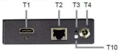
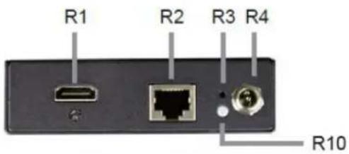


| Position Name Effect | ||
| T1: | Video Connector | |
| R1 | Connect to the HDMI source | |
| Connect to the HDMI monitor | ||
| T2 R2: | RJ-45 Jack | Connect to an PoE Switch(IGMP Gigabit PoE Switch recommended) |
| T3 R3: | Reset Button System reset | |
| T4 R4: | Power Supply DC power input | |
| T5 R5: | B2 Push Button | Refer to Push Button Control section |
| T6 R6: | B1 Push Button | |
| T7 R7: | Rotary DIP Switch Channel ID Select | |
| T8 R8: | Control Port System control (reserved) | |
| T9 R9: | AUX/EXT Port Data communication (reserved) | |
| T10 R10: | Network Status LED Flashing: Connected to Ethernet network | |
| T11: | Link / Power LED | Blue: Link OKGreen: Video unlinkFlash Blue + Green: Linking and searching video source |
| R11 | Blue: Link OKRed: Video UnlinkFlash Blue + Red: Linking and searching video source | |
LED Definition
| LED Unit Status Description | |||
| Network Status | Tx/Rx | Flashing Connected to network | |
| Off Abnormal | |||
| Link / Power | Tx | Green Unlink | |
| Blue Link OK | |||
| Flash Blue + Green | Linking and searching source | ||
| Rx | Red Unlink | ||
| Blue Link OK | |||
| Flash Blue + Red Linking and searching source | |||
Button Definition
| Button | Unit | Function |
 | IHD-200PT&IHD-200PR | ● Press once - Link/ Unlink video |
| ● Factory Default Setting with steps below: Power off the unit →Press and hold the button → Power on the unit → Release the button after 17 sec. (the Power / Link LED flashes green / red & blue) → Re-power the unit | ||
 | IHD-200PT | ● Press for 1 sec. - Select Graphic Mode or Video Mode (also deploy to all the IHD-200PT and IHD-200PR of the same channel) (Default: Graphic Mode) |
| ● Press for 3 sec. - Enter Anti-Dither Adjustment Mode: Level 1 / Level 2 / Off (also deploy to all the IHD-200PT and IHD-200PR of the same channel) (Default: Off) | ||
| IHD-200PR | ● Press for 1 sec. - Select Graphic Mode or Video Mode (also deploy to all the IHD-200PT and IHD-200PR of the same channel) (Default: Graphic Mode) | |
| ● Press for 3 sec. - Enter Anti-Dither Adjustment Mode: Level 1 / Level 2 / Off (also deploy to all the IHD-200PT and IHD-200PR of thesame channel) (Factory Default: Off) | ||
| ● EDID Copy with steps below: Power off the unit → Press and hold the button →Power on the unit → Release the button after 12 sec. (the Network Status LED flashes yellow) |
1.6 Device Connection Topology
Video Extender
The IHD-200PT and IHD-200PR are able to send the same video signal to multi-monitors in different locations at the same time. It helps to quickly extend the image and commercial to the public efficiently in such places as expos, food courts, boardrooms, and any public areas.
![graph TD A["Video Source"] --> B["Video Extender"] B --> C["Rx"] C --> D["PoE Switch"] D --> E["Tx"] E --> F["IHD-200PT Transmitter"] E --> G["IHD-200PR Receiver"] style A fill:#f9f,stroke:#333 style B fill:#ccf,stroke:#333 style C fill:#cfc,stroke:#333 style D fill:#fcc,stroke:#333 style E fill:#cf…](/content/2026/05/1089544/images/775990b9e7059ac22a299c0cad8ee28dc36a0039b66db76531518dfd34837e8b.jpg)
Video wall
To bring the image and picture in larger size over video wall, the IHD-200PT and IHD-200PR are the ideal solution to distributing one specified image, picture, or video to multiple screens which are usually applicable for sports, department stores, movie theaters, etc.
![graph TD A["Video Source"] --> B["Video Wall"] B --> C["Pioneer of ITP Innovation"] C --> D["HDMI"] C --> E["IHD-200PT Transmitter"] C --> F["IHD-200PR Receiver"] B --> G["Rx"] B --> H["Rx"] B --> I["Rx"] B --> J["Rx"] B --> K["Rx"] B --> L["Rx"] B --> M["Rx"] B --> N["Rx"] B --> O["Rx"] B --> P["Rx…](/content/2026/05/1089544/images/0a02d574f500bc2dea904ae62bfacd4c72a6df93ea432475318903b1c037d800.jpg)
Efficient Control via 16 Channels Selectable DIP Switch
Where there is more than one transmitter in the video wall system, the rotary DIP switch in the IHD-200PT and IHD-200PR facilitates distinguishing the pair of the transmitter and receiver units in the same channel. It further enables the broadcasting system to perform multi functions including Video Extender and Video Wall simultaneously through matching of the IHD-200PT and IHD-200PR.
![graph TD A["Video Source"] --> B["Tx0"] B --> C["PoE Switch"] C --> D["Rx0"] D --> E["Video Output"] B -->|Channel ID n| C C -->|Channel ID n| D style A fill:#f9f,stroke:#333 style B fill:#ccf,stroke:#333 style C fill:#cfc,stroke:#333 style D fill:#fcc,stroke:#333 style E fill:#cff,stroke:#333](/content/2026/05/1089544/images/5c152d2e7aecb8cb796fff5493feabe611c94ab86f245dff8557af0b788c2383.jpg)
Combining the two functions
The selectable 16-channel DIP switch is applied to combine the two main functions as shown in the following diagram:
![graph TD A["Video Source"] --> B["PC"] A --> C["DVD Player"] A --> D["Blu-ray Player"] B --> E["Tx"] C --> F["Tx"] D --> G["Tx"] E --> H["PoE Switch"] F --> H G --> H H --> I["HDMI"] H --> J["1000Base-T UTP with PoE"] H --> K["Video Wall"] H --> L["Video Extender"] L --> M["Rx"] L --> N["Rx"] L -->…](/content/2026/05/1089544/images/3cea365fda5cdf8a4eb0b99d0a1f05e9262803e2a8eb04789b9cddd9a99daab4.jpg)
Chapter 2: Hardware Installation
- The Unit-Cast application is Plug-and-Play basis. It's easy to install in seconds.
● The Multi-Cast application can be used as multi-to-multi and video wall which is suitable for digital signage.
2.1 Installation Instructions
System Requirements
- HDCP compliant monitors with HDMI interface for the HDCP video source
- CAT5 / 5e / 6 UTP cable (EIA / TIA 568B industry standard compliant)
- PoE Switch (see Recommended PoE Switch)
| Application Recommended Ethernet Switch | |
| Video Wall Application Gigabit PoE | Switch, IGMP & Snooping function |
| Multiple Video Wall Application | Gigabit PoE Switch, IGMP, Snooping function & VLAN function |
Operation:
The LED on the Extender Units shows the real-time status indicating the linking and communication between the Transmitter/Sender Unit and the Receiver Unit. Users can identify the current status through the LED indicators on the unit.
The quality of the output signal will depend largely upon the quality of video source, cable and display device used. Low quality cables degrade output signal causing elevated noise levels. Please use the proper cable and make sure the display device is capable of handling the resolution and refresh rate selected.
Step 1
Connect the video source to the Transmitter / Sender Unit.
Step 2
Connect the monitor to the Receiver Unit.
Step 3
Use CAT5 cables (EIA / TIA 568B industry standard compliant) for connection between TX / RX and Gigabit PoE Switch.
Step 4
Set an identical ID number on Rotary DIP Switch for all Units of the same group.
Step 5
User still could apply the proper power to all connecting devices if without PoE switch.

WARNING!
- Ensure that all devices are powered off before connecting to the Unit.
- Make sure all devices you will connect to are properly grounded.
- Place cables away from fluorescent lights and air conditioners machines that are likely to generate electrical noise.
- Please allow adequate space around the unit for air circulation.
Chapter 3: Internet Connection Setup
3.1. Using Bonjour Browser.exe
After the device connection is complete, you have to use the utility called "Bonjour Browser" to get to the Web UI to do the configuration.

The following picture is the interface of Bonjour Browser.
①: Click Web Server (HTTP) and theoretically, you can see all the devices connected to the same hub/switch (over the same LAN) that are shown on the right side of the grid.
②: Ast-gateway: It represents transmitter.
The four digits after ast-gateway depend on the position of the Rotary Switch you've set. Please refer to the form below. For example, if the position is set up as 7, then you'll see ast-gateway1110.
| Rotary Switch | 0 1 | 2 3 4 | 5 6 7 | |||||
| Four digits | 0000 | 1000 0 | 100 110 | 000010 | 1010 0 | 110 1 | 110 | |
| Rotary Switch | 8 | 9 | A | B | C | D | E | F |
| Four digits | 0001 | 1001 0 | 101 110 | 010011 | 1011 0 | 111 1 | 111 |
③: The IP address of transmitter side.
④: Ast-client: It represents receiver.
⑤: The IP address of receiver side.
⑦: You can see the information here.
⑥: Beware, even though the name of receivers are the same, you can tell the difference by the IP address.

After PC's IP Setting is complete, double click the device's name and then get to the Web UI to do the configuration.
3.2. Setting TCP/IP on your PC
If you are using Windows XP, do as follows:
- From the desktop, right-click My Network Places > Properties.
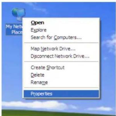
- Right-click on the Local Area Connection and select Properties.

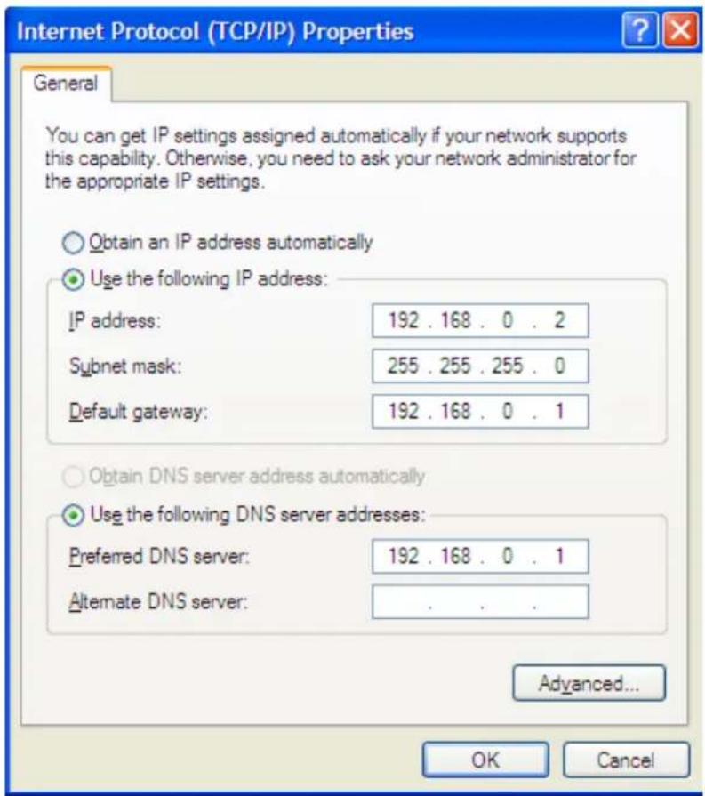
- Select Internet Protocol (TCP/IP) and click Properties.

- Select "Use the following IP address".
IP address: You have to set the same network segment between your PC's IP and the transmitter / receiver.
Ex: If the transmitter's IP is 169.254.0.157, then you should set 169.254.0.xxx where xxx can be any number between 2 and 253. (same as receiver)
Subnet mask: Enter 255.255.0.0.
- If necessary, you may enter "Advanced" to add more that one IP address.

Generally, except for updating firmware, you only need to set the same network segment between your PC's IP and the transmitter to configure all the receivers.
If you are using Windows 7, do as follows:
- Click on Start > Control Panel > Network and Internet > Network and Sharing Center.

- Click "Change adapter settings".

- Right-click on the Local Area Connection and select Properties.
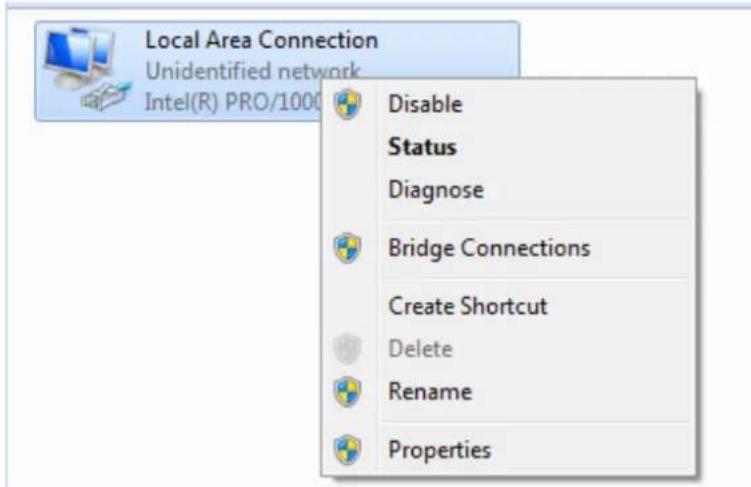
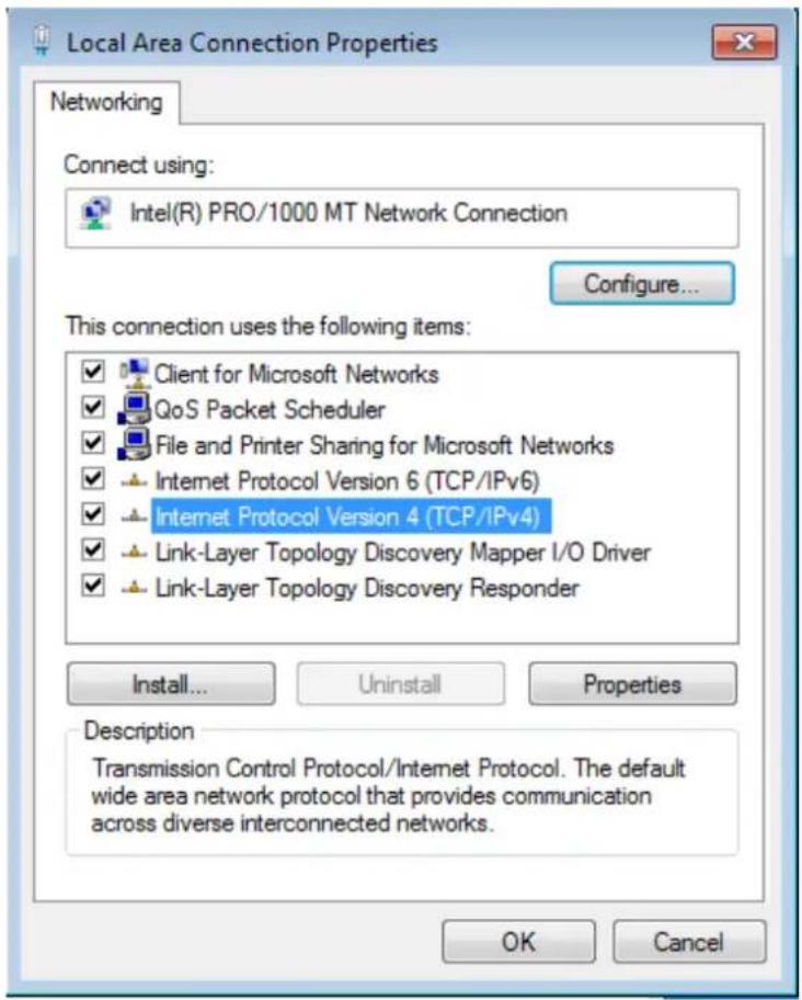
- Select Internet Protocol Version 4 (TCP/IPv4) and click Properties or directly double-click on Internet Protocol Version 4 (TCP/IPv4).
- Select "Use the following IP address".
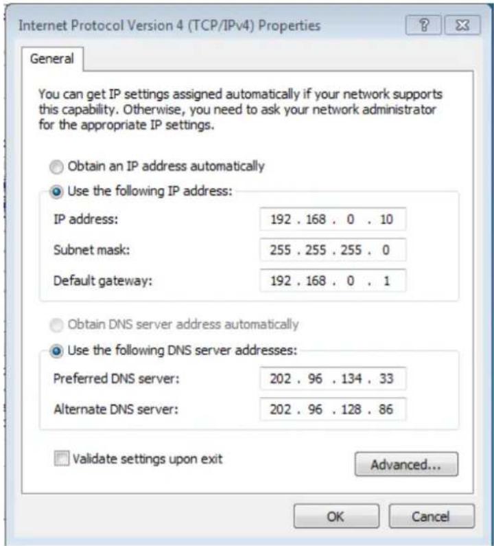
Select "Use the following IP address".
IP address: You have to set the same network segment between your PC's IP and the transmitter / receiver.
Ex: If the transmitter's IP is 169.254.0.157, then you should set 169.254.0.xxx where xxx can be any number between 2 and 253. (same as receiver)
Subnet mask: Enter 255.255.0.0.
- If necessary, you may enter "Advanced" to add more that one IP address.

Generally, except for updating firmware, you only need to set the same network segment between your PC's IP and the transmitter to configure all the receivers.
Chapter 4: Web UI Function Instructions
Getting to Web UI to do Configuration
- Before doing configuration, ensure that all remote displays and all network cables are connected correctly. (Video source is required.)
- Double click the device's name in Bonjour Browser and then get to the Web UI, or you can simply type the device's IP in the address bar.(ex://169.254.xxx.xxx)
If the link is successful, user will see the web page as follows:
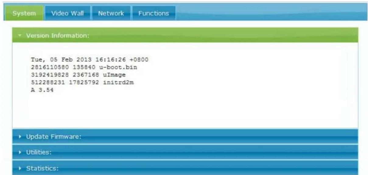
4.1 System
4.1.1. Version Information
Here user can see the current date and the firmware version information.
4.1.2. Updating Firmware
Here is for user to update firmware. Some functions or issues may have to be improved by updating the firmware. For more details, please refer to chapter 7.
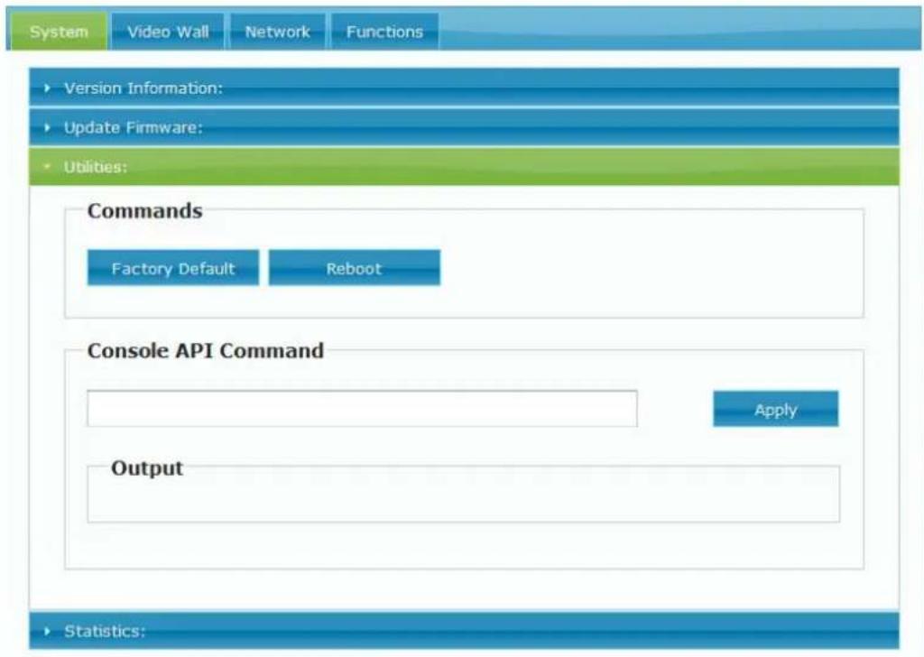
4.1.3. Utilities
User can do factory default and reboot, even console API command is issued here.
(Usually, the API command is for engineers to use, but not for endusers.)
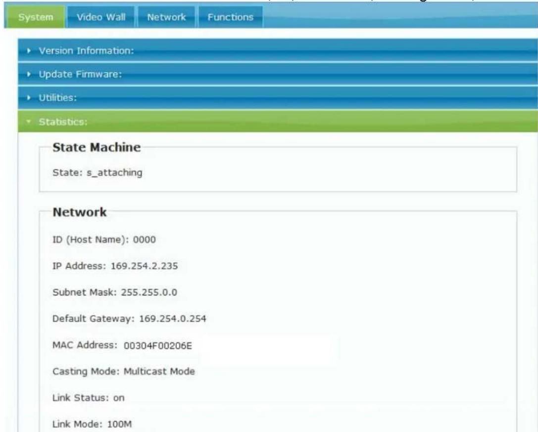
4.1.4. Statistics
Below is the detailed information on ID, IP, unit status, casting mode, etc.
4.2 Video Wall
4.2.1. Basic Setup
Click on Video Wall Setup tab for Basic Setup first.

1. Bezel and Gap Compensation:
| OW = Outside Width | OH = Outside Height |
| VW = View Width VH | = View Height |
Adjust dimensions (mm) for the monitors of video wall. If you don't need this, just set all values "OW=VW, OH=VH." And please note that the unit is 0.1mm and the value must be an integer.

Basic Setup:
Bczcl and Gap Compensation


2. Wall Size and Position Layout:
Step 1
Vertical Monitor Count x Horizontal Monitor Count: If the video wall is 2 x 2, then set up Vertical Monitor Count and Horizontal Monitor Count as 2. (maximum: 8 x 8)
Step 2
Single Host Mode: Must check this item for single host application.
Single Host Mode
Step 3
Apply To: Select "All" and check "Apply" button for your settings and all screens will refresh.
Apply To: "All" device(s) in the list

3. Configuring row and column position for each display
- OSD: On-Screen Display. The system automatically assigns a number to each monitor.
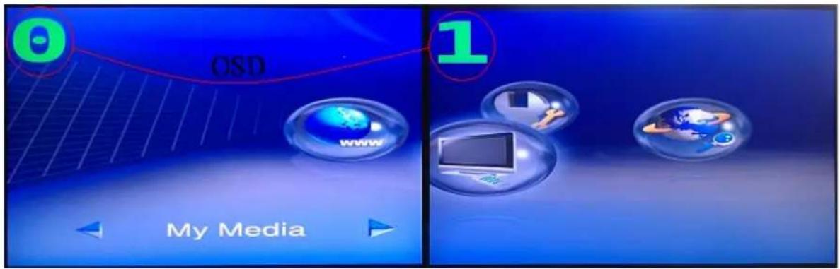
User can according to the number do individual control with the corresponding receiver's IP.
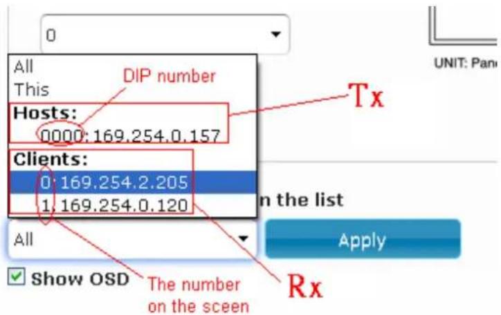
● Vertical Monitor Count: The number of monitors on vertical line.
● Horizontal Monitor Count: The number of monitors on horizontal line.
- Row Position: Set up row position for a monitor. For example, if the monitor is situated on the 1st row, the row position should be 0; if the monitor is situated on the 2nd row, the row position should be 1.
- Column Position: Set up column position for a monitor. For example, if the monitor is situated on the 1st column, the column position should be 0; if the monitor situated is on the 2nd column, the column position should be 1.
4.2.2. Setup Step (Examples)
1. 1 x 2 video extender
If you want to set a 1 x 2 "video extender" as shown in the following picture, you may refer to the following table and see the steps below:

| OSD 0 1 | ||
| Vertical Monitor Count 1 | 1 | |
| Horizontal Monitor Count | 1 | |
| Row Position 0 0 | ||
| Column Position 0 0 | ||
1
2. 1 x 2 video wall
If you want to set a 1 x 2 "video wall" as shown in the following picture, you may refer to the following table and see the steps below:

| OSD 0 1 | ||
| Vertical Monitor Count 1 | 1 | |
| Horizontal Monitor Count 2 | 2 | |
| Row Position 0 0 | ||
| Column Position 0 1 |
Step 1
Show OSD: Check this item and all monitors will show their number on the screen.
Step 2
Row Position / Column Position: Decide which part of the screen will be applied to a monitor.
Step 3.
Apply To: Select one of the clients (OSD number) for the following setting.
Step 4
For all monitors setup; please follow the above steps 1 to 3.

After all settings are done, you can uncheck OSD item.
3. 2 x 2 video wall
Part 1: Wall Size and Position Layout

Part 2: Configuring row and column position for each display
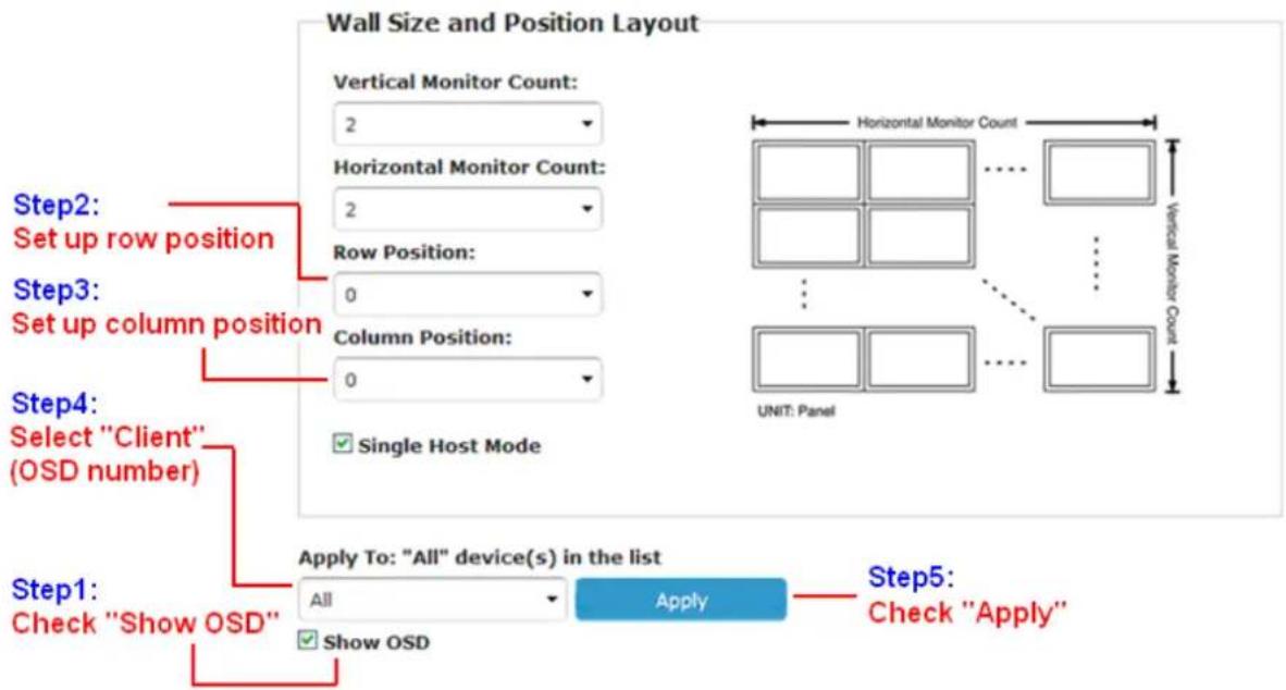
To set up "Row Position" and "Column Position", you can refer to the Coordination below:
Wall Size and Position Layout


For video wall application, it is NOT suggested to set up your screen array as N (row) x 1 (column) when horizontal resolution is greater than 1280 pixels.
4.2.3. Advanced Setup
After the Basic Setup is done, users may enter this tab for advanced setting. Please note that each monitor should have its own part of the screen section and does not overlap.

Step 1: Choose Control Target
Show OSD: Check this item and all monitors will show their number on the screen
![graph TD A["Select all clients (monitors)"] --> B["Step 1: Choose Control Target"] C["Select one row"] --> D["Block 1"] E["Select one column"] --> F["Block 2"] G["Block 3"] --> H["Block 4"] I["Block 5"] --> J["Block 6"] K["Block 7"] --> L["Block 8"] M["Block 9"] --> N["Block 10"] O["Block 11"] --> P…](/content/2026/05/1089544/images/8988cd0fd8b4a9dc8345bc9e6531b9f4fe444a64abb193d372d152a31d456f5a.jpg)
Step 2: Control Options
Single Host Mode: Must check this item for single host application
Horizontal Scale Up & Vertical Scale Up: It is NOT suggested to configure these two items for it may result in flickering images.

4.2.4. Tearing Delay
Screen tearing may occur when the video feed to the device isn't in sync with the display's refresh or lack of sync between two equal frame rates. During video motion, screen tearing creates a torn look as edges of objects fail to line up. To solve this issue, the HDMI over PoE IP Extender provides three ways by:
- Switching to different video resolution
- Setting up Tearing Delay value via GUI control. The typical value is 10000\~16000 µ s. Before setting up Tearing Delay, users need to choose control target (each or several rows) and perform Tearing Delay individually.

- Hardware solution: Using multiple Tx units. The following is a 4 x 4 example of hard solution.
Steps:
- Add more Tx units to the system for each row, and set up the ID number for each Rx unit; see below.

To connect multiple Tx units, you can use multiple ports HDMI splitter.
![graph TD A["Video Source"] --> B["HDMI Splitter"] B --> C["Ethernet Hub/Switch"] C --> D["ID=0"] C --> E["ID=1"] C --> F["ID=2"] C --> G["ID=3"] D --> H["Rx1a"] D --> I["Rx1b"] D --> J["Rx1c"] D --> K["Rx1d"] E --> L["Rx2a"] E --> M["Rx2b"] E --> N["Rx2c"] E --> O["Rx2d"] F --> P["Rx3a"] F --> Q["Rx…](/content/2026/05/1089544/images/770f6bb42f6323d446f881c33eb02d6efa3857cb801e6ecdf0eb2de86f759deb.jpg)
-
Enter "Video Wall Setup"
-
Set up "Wall Size and position Layout"
-
Un-check "Single Host Mode"
Single Host Mode
-
Set up Vertical/Horizontal Monitor Count; for example, 4 x 4.
-
Set up Row/Column Position of Tx units:
a). Choose a host (Tx); the ID number (4 digits) should refer to rotary switch position (1\~F); see Rotary Switch chart.

b). The row & column positions of 1st row should be 0 & 0. The 2nd row is 1 & 0. The 3rd row is 2 & 0, and so forth.
For example: The ID number of "Tx 1 host" is 0000, and the row/column position should be 0 & 0.

c). Press "Apply"

- Set up Row/Column Position for each client; see Video Wall Setting-Basic Setup.

4.3 Network
User can set the IP mode of each unit here and also can change the casting mode.
4.3.1. IP Setup
Auto IP: Factory default IP.
DHCP: IP dispatched from DHCP server.
Static: IP setting by user.
4.3.2. Casting Mode
Multicast: Multicast is a true broadcast. The multicast source relies on multicast-enabled routers to forward the packets to all client subnets that have clients listen.
Unicast: Unicast is a one-to-one connection between the client and the server. Unicast uses IP delivery methods such as Transmission Control Protocol (TCP) and User Datagram Protocol (UDP), which are session-based protocols.

4.4 Function
Here user can make settings for IHD-200 PoE series.
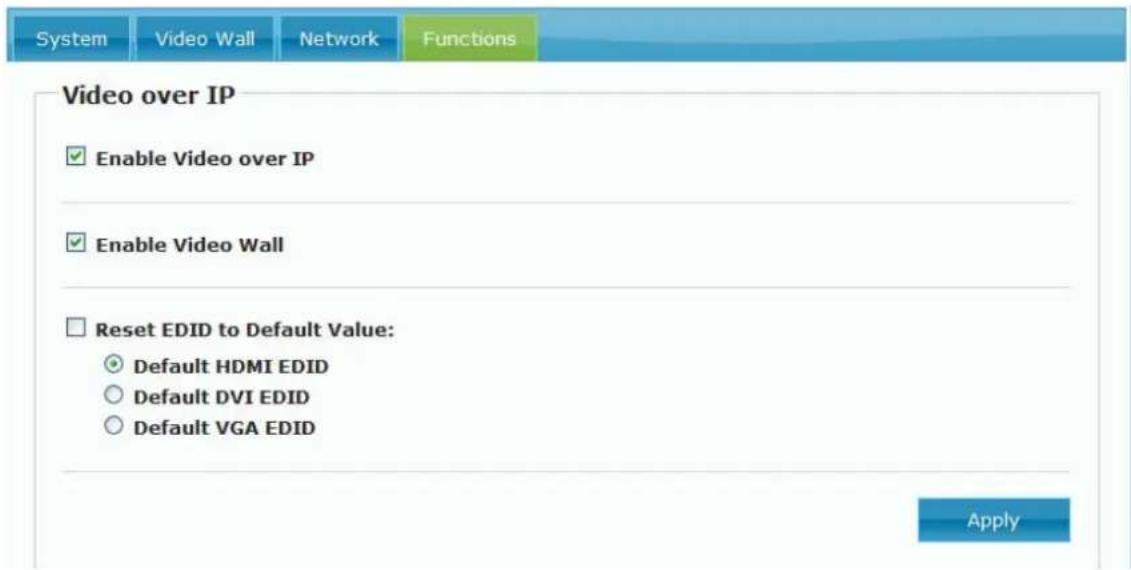
4.4.1. Video over IP
Enable Video over IP: If user unchecks this item, then it can't work.
Enable Video Wall: If user unchecks this item, then video wall function can't be used; only extender can be used.
Reset EDID to Default Value: User can copy the EDID from this Rx to other Rxs with the same ID. (the same group)
4.4.2. Serial over IP
Enable Serial over IP: If user unchecks this item, then serial 2 can't be used.
Operation Mode:
Type 1 and Type 1 guest modes have to do other commands.
Type 2 (extender transmit) and Type 2 guest mode use telnet through port 6752. (Usually, the API command is for our engineer to use, but not for end users.)
Baudrate Setting: User can set baudrate here for the unit.
Serial over IP
Enable Serial over IP
Operation Mode:
○ Type 1 (Need extra control instruction. For advanced usage.)
Type 2 (Recommended. Dumb redirection.)
○ Type 1 guest mode
○ Type 2 guest mode
Baudrate Setting for Type 2:
| Baudrate: | 9600 |
| Data bits: | 8 |
| Parity: | None |
| Stop bits: | 1 |
Apply
Chapter 5: EDID Instruction
5.1 EDID Configuration
EDID (Extended Display Identification Data) is greatly important which contains information about manufacturer name and serial number, product type, maximum image size, color characteristics, factory pre-set timings, frequency range limits, etc. In some cases display problems may occur due to incorrect EDID communication between the display monitor and the unit or inappropriate EDID data programmed by display manufacturers. Therefore, by adopting “EDID COPY” function, it will allow the system to copy EDID information from EDID compliant displays in order to assure accurate display performance.
EDID Copy (on Receiver Unit only)
Step 1
Power off the unit.
Step 2
Press and hold the button B2.
Step 3
Power on the unit.
Step 4
Release the button after the Network Status LED flashes.
However, owing to a variety of monitor models, EDID data may not be usable to all. For example, if you use an HDMI-to-DVI converter to a REAL DVI monitor, the copied EDID (DVI) data may NOT be applicable to HDMI monitors. On the other hand, if using an HDMI-to-DVI converter to a DVI monitor (but in fact it's an HDMI monitor with DVI connector), the copied EDID (HDMI) data may be applicable to HDMI monitors.

-
Using HDMI or DVI for all monitors; do not mix them up in one system.
-
It is suggested to use monitors with identical brand and type.
Chapter 6: Display Quality Adjustment
6.1 Graphic Mode & Video Mode
User can press Button "B2" for once(less than 1 sec.) and then convert these two modes. (default is Graphic Mode)
Graphic Mode: It's usually for the static state video. Pictures are the main display contents, and the pixel update processing is not so fast. The CPU consumption is lower than video mode.
Video Mode: It's usually for the dynamic state video. Videos are the main display contents, and the pixel update processing is fast. The CPU consumption is higher than graphic mode.
6.2 Anti-Dither
User can press Button "B2" for 3 seconds (till the subtitle appears) and then convert three levels of Anti-Dither. (default is Anti-Dither off)
There are 3 levels of Anti-Dither:
It would probably cause “Motion Blur” or “Broken Map” when user plays the high quality video, but after “Anti–Dither” adjustment, it can be improved.
Anti-Dither 2: It's the worst performance.
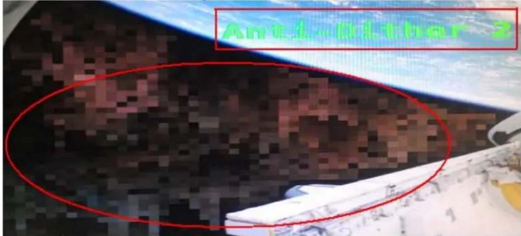
Anti-Dither 1: It's better than Anti-Dither 2.

Anti-Dither off: It's the best performance.

6.3 Conclusion
After changing modes and Anti-Dither adjustment, we can improve the display quality.
Below is the performance from the worst to the best.
| Graphic Mode | Graphic Mode | Graphic Mode | Video Mode | Video Mode | Video Mode |
| Anti-Dither 2 | Anti-Dither 1 | Anti-Dither off | Anti-Dither 2 | Anti-Dither 1 | Anti-Dither off |
| WORST | BEST | ||||
Chapter 7: Firmware Updating
7.1 Updating Environment
- We suggest you to use Safari browser because the BonjourSDKSetup is embedded.
If you use Google Chrome browser or other browsers, you should install BonjourSDKSetup on your PC. (IE is not recommended)

Google "bonjourSDK download" for the installation file or download: http://developer.apple.com/opensource/
- Make sure your computer and units are connected to the same hub/switch. Then power on, and run Bonjour Browser.exe prepare to get to the Web UI.
(To know how to use Bonjour Browser.exe, please refer to 3.1 Using Bonjour Browser.exe)
7.2 Updating Step

Beware! if you want to update firmware for transmitter, please get to transmitter's Web UI; if you want to update firmware for receiver, please get to the receiver's Web UI.

Ast-client: It represents receiver.
Ast-gateway: It represents transmitter.
Step1: Getting to the Web UI System tab and then choose "Update Firmware"

Step2: Click "Choose File", and then select the right firmware and final click "Upload".
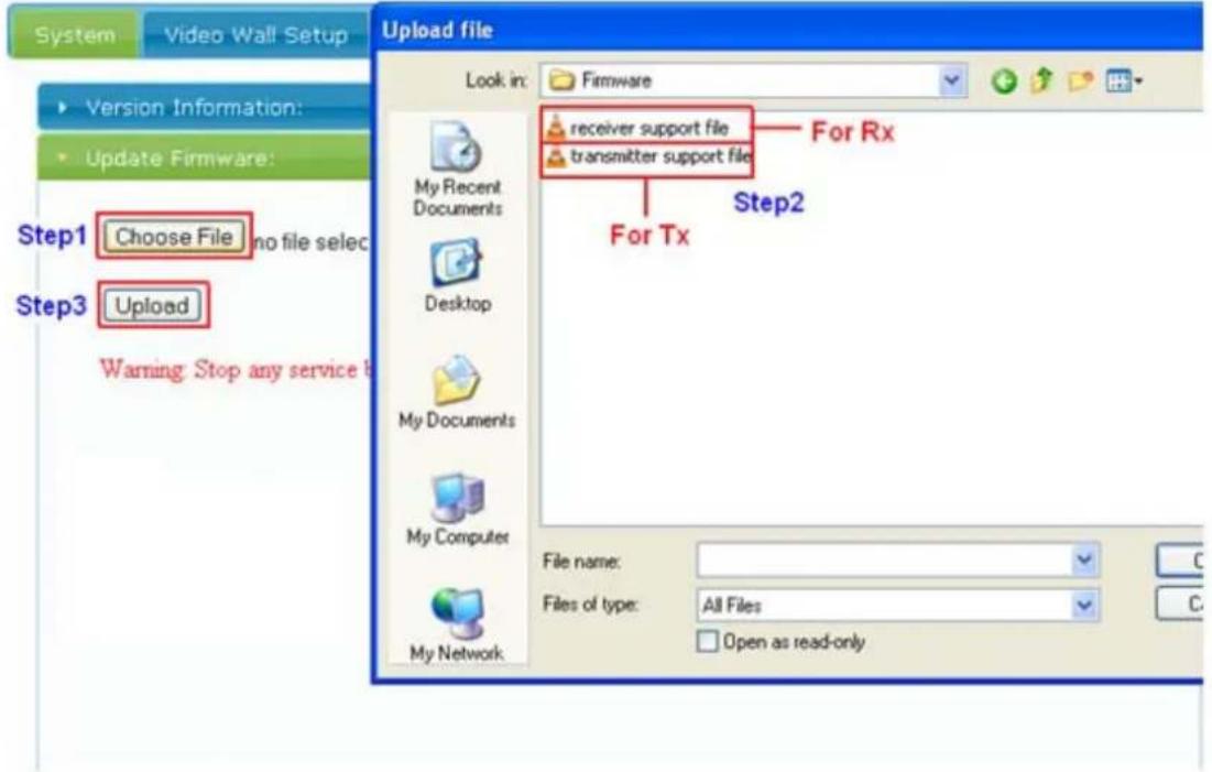

There are two different kinds of firmware available: one for transmitter and the other for receiver. The transmitter firmware must be uploaded to the transmitter unit, and the receiver firmware must be uploaded to the receiver unit. Uploading the
wrong firmware to the wrong unit will cause the unit to malfunction.
Step 3: The upload will take around 5 minutes. After 100% complete, the unit will automatically reboot. The reboot will take 25 seconds. Any interruption during the upload will cause the unit to malfunction.

Step4: Repeat Step 1 through Step 3 for the 2nd unit, 3rd unit, and so on.
Chapter 8: VESA Mounting Bracket
8.1 How to Install
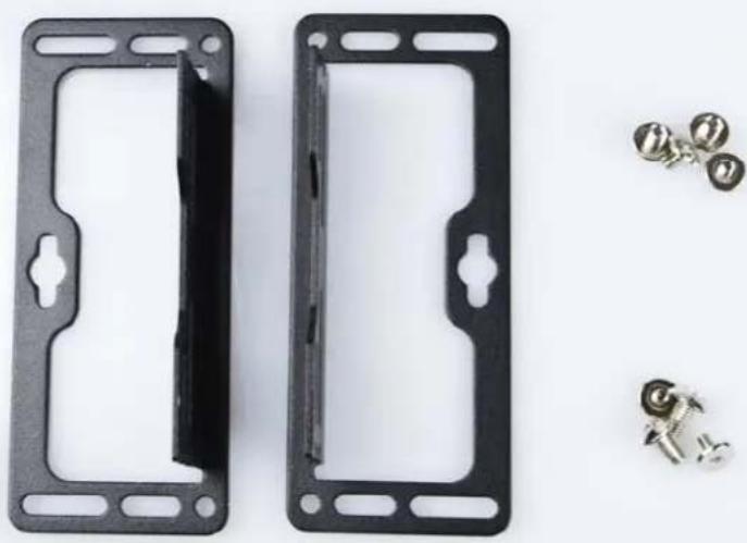
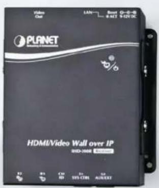
You can use the VESA Mounting Bracket to fix the unit behind the screen or on the wall anywhere you like.
You can refer to the following pictures:
- VESA Mounting Bracket and screws.
- Provides two ways to install. (Front)

- Provides two ways to install. (Back)


- Provides two ways to install. (Side)


Appendix FAQ
| Q1: Where is the Bonjour Browser.exe utility? |
| A: Basically, there are so many third - party search tools can be used, as long as you can find the IP of the unit. If you want to use Bonjour Browser.exe please e-mail to us and we will provide it to you. |
| Q2: What kind of switch should user use for this product? |
| A: We strongly advise user to use the switch which supports IGMP snooping function (V2 is fine), Gigabit Ethernet.As for PoE, IHD-200 PoE series has passed Mid-span and End-span testing. By the way, the power consumption is 13.5W for each unit. |
| Q3: Can I use power line with this product? |
A: Yes, you can use power line instead of switch to work it. Please refer to the topology below: |
Q4: Should user use the security DC adapter connector?
A:
No, the normal DC adapter connector is fine, please refer to the photo below. Both of the two connectors can be plugged in, but the left one can be tightened.

Q5: How can I convert the video source?
A:
There are three ways to convert the video source. One is to use DIP switch, while the other is to set VLAN port and go with HDMI splitter (matrix).
- A Tx (transmitter) supports DIP switch for 16 channels, and every time when you convert the source you have to switch DIP of all units to the same number, and then reboot all the units.
![graph TD A["Video Source"] --> B["Tx0"] B --> C["Channel ID n"] C --> D["Rx0"] D --> E["Video Output"] B --> F["PoE Switch"] F --> G["Rx1"] F --> H["Rx2"] F --> I["Rx3"] style A fill:#f9f,stroke:#333 style B fill:#ccf,stroke:#333 style D fill:#ccf,stroke:#333 style E fill:#cfc,stroke:#333 style F fi…](/content/2026/05/1089544/images/76291c5b3634ab2aab01a332941da3b8bc63d751b4978ff44dec056179868238.jpg)
- You can set VLAN to convert the video source, please refer to the topology below
and imagine that the concept is based on your issue.
![graph LR A["Sources"] --> B["Tx"] C["Sources"] --> D["Tx"] B --> E["Switch"] D --> E E --> F["Rx"] F --> G["1 & 3 → VLAN"] F --> H["2 & 4 → VLAN"]](/content/2026/05/1089544/images/1b390ee1f80997447f68d3f4cdc7e8ec1dedbcdb76e707fce8ce8d13fc960e7c.jpg)
![graph LR A["Sources"] --> B["Tx"] C["Sources"] --> D["Tx"] B --> E["Switch"] D --> E E --> F["Rx"] F --> G["1 & 3 → VLAN"] G --> H["Issue command via telnet"] I["WGSW-24040"] --> J["1 & 3 → VLAN"] I --> K["2 & 3 → VLAN"]](/content/2026/05/1089544/images/8afc4839974bfc0ff3a5833b2667fba7d3801aba97590a1367b111b62871b269.jpg)
You can set up port-based VLAN for that Transmitter (IHD-200PT), and then for the receiver (IHD-200PR), You can just dynamically swap the receiver port to a different VLAN for video source change. You can swap VLAN via Web interface of the switch, say, WGSW-24040.
However, to be faster and easier to swap the sources, you can consider using TELNET or RS232 Console via CLI (command line).
Since the commands are just fixed commands, you can record those commands into a macro, and just double click on specified macro, and then the commands will be sent to the switch in a very short time and swap your video source. By the way, in this setting, all the transmitter(s) and receiver should set as the same group.
Instructions about the topology above:
As for Test A, we set port1 and port3 to a VLAN, and set port2 and port4 to another VLAN. The Rx will convert the source if we change the connection of Rx and switch from port3 to port4.
As for Test B, we set port1 and port3 to a VLAN, and the Rx will convert the source if we issue the command via telnet to set port2 and port3 to a VLAN.
- You also could use HDMI splitter (matrix) to do the sources convert.
![graph LR A["Source1"] --> B["4 in 2 out HDMI Matrix"] C["Source2"] --> B B --> D["Tx"] D --> E["Switch"] F["Rx"] --> E E --> G["Output"] style A fill:#000,stroke:#fff,color:#fff style C fill:#000,stroke:#fff,color:#fff style B fill:#000,stroke:#fff,color:#fff style D fill:#000,stroke:#fff,color:#fff…](/content/2026/05/1089544/images/cf5cf74fa8248d5cee6093b6ea900f3d6d85938a4d7b63536f629fb82eadf53e.jpg)
As you see, two sources connect to the input of HDMI matrix, and output to Tx, and then Tx and Rx all connect to the switch.
In this case, we use the HDMI matrix controller to select the source, of which one should be transmitted.
Q6: Users encounter no screen display in computer connection.
A:
- Make sure the device cables are correctly and firmly attached.
- Set your display device's (TV, monitor, etc.) input source as HDMI.
- Check the PC BIOS configuration about the video output setting.
- Connect your computer to the HDMI Display DIRECTLY to check if the video signal gets through.
- Slide the Rotary DIP Switch to the correct position.
- Inappropriate EDID data. Apply EDID Copy to your display.
Please refer to the 4.1 EDID Configurations. - Please reboot or disconnect and connect again.
Q7: Do I have to use the same screen resolution to set video wall?
A:
We suggest user to use the same screen resolution to set video wall so that user can get the best performance. If user uses the different screen resolution please try "EDID copy" to solve no display issue. (But video extender accepted.)
Q8: What's the maximum limit distance between input video source and output video?
| A:Point-to-point and multi-cast is 100 meters. But if the connection via switches, theoretically, there is no limit distance. It depends on the cable and switch level you use. (Giga Ethernet switch is recommended or higher level.) |
| Q9: What's the maximum of Rx units can be linked via one Tx unit? |
| A:Video Wall: 8 x 8.Video Extender: Theoretically, 1000 are the most, as long as each Rx unit is assigned to an IP from 65534 IP. |
| Q10: Why did it fail when updating firmware? |
| A:1. If user doesn't use Safari browser, please download BonjourSDKSetup on PC. (IE browser is not recommended.)2. Then choose the right firmware for the right unit (click in the right Web UI).3. Do not interrupt while updating.4. User should update every unit. (For example, if there are 3 Rx's, user should update for 3 times.) |
| Q11: I wanted to do Rx individual configuration, but why couldn't I see all the Rx's in the drop-down list? |
| A:Please make sure you entered the Web UI of Tx unit. |
| Q12: How can I connect two or more Tx's? |
| A:User can use HDMI splitter with two or more ports to connect. |
| Q13: About HDCP issue. |
| A:The system will disable the video output signal when it detects non-HDCP compliant display(s) playing the HDCP video source. All the connected output displays MUST be HDCP compliant while the video source is HDCP compliant. |
| Q14: Why is Full HD video source watched on a non Full HD monitor is so blur or choppy? |
| A:We suggest user do not use the low-resolution monitor to watch the higher quality video source. The screen resolution can only be backward compatible, not forward compatible. So please adjust the video source resolution appropriate for the output screen resolution. |
Q15: What is the function of the screw hole over the HDMI port?
A:
Please refer to the following picture.
Step 1: Unscrew the screw from the device.

Step 2: Then you will see the screw hole.

Step 3: Tighten the security screw onto the device.

Step 4: Plug in the HDMI cable and tighten the screw to secure.
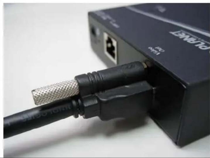

- HDMI / VIDEO WALL OVER IP WITH POE
- COPYRIGHT
- DISCLAIMER
- FCC COMPLIANCE STATEMENT
- CE MARK WARNING
- WEEE
- TRADEMARKS
- REVISION
- CONTENTS
- CHAPTER 1: PRODUCT INTRODUCTION....5
- CHAPTER 2: HARDWARE INSTALLATION....16
- CHAPTER 3: INTERNET CONNECTION SETUP ....18
- CHAPTER 4: WEB UI FUNCTION INSTRUCTIONS....25
- CHAPTER 5: EDID INSTRUCTION....40
- CHAPTER 6: DISPLAY QUALITY ADJUSTMENT....41
- CHAPTER 7: FIRMWARE UPDATING....43
- CHAPTER 8: VESA MOUNTING BRACKET ....46
- APPENDIX FAQ 48
- CHAPTER 1: PRODUCT INTRODUCTION
- 1.1 PACKAGE CONTENTS
- 1.2 PRODUCT DESCRIPTION
- PRODUCT FUNCTION
- HIGH-SPEED ETHERNET CONNECTION VIA GIGABIT ETHERNET
- EXCLUSIVE VIDEO TRANSMISSION BY IGMP MULTICAST TECHNOLOGY
- EXTENDED DISPLAY IDENTIFICATION DATA (EDID) SUPPORT
- EASY VIDEO CHANNEL MATCHING THROUGH NETWORK CONFIGURATION
- HIGH QUALITY OUTPUT AND PERFORMANCE
- 1.3 PRODUCT FEATURES
- HDMI NETWORK
- VIDEO OUTPUT CHARACTERISTICS
- EASY INSTALLATION & MANAGEMENT
- 1.4 PRODUCT SPECIFICATIONS
- 1.5 PHYSICAL DESCRIPTION
- 1.6 DEVICE CONNECTION TOPOLOGY
- VIDEO EXTENDER
- VIDEO WALL
- EFFICIENT CONTROL VIA 16 CHANNELS SELECTABLE DIP SWITCH
- COMBINING THE TWO FUNCTIONS
- CHAPTER 2: HARDWARE INSTALLATION
- 2.1 INSTALLATION INSTRUCTIONS
- SYSTEM REQUIREMENTS
- OPERATION
- STEP 1
- STEP 2
- STEP 3
- STEP 4
- STEP 5
- CHAPTER 3: INTERNET CONNECTION SETUP
- USING BONJOUR BROWSER.EXE
- SETTING TCP/IP ON YOUR PC
- IF YOU ARE USING WINDOWS 7, DO AS FOLLOWS
- CHAPTER 4: WEB UI FUNCTION INSTRUCTIONS
- GETTING TO WEB UI TO DO CONFIGURATION
- 4.1 SYSTEM
- VERSION INFORMATION
- UPDATING FIRMWARE
- UTILITIES
- STATISTICS
- 4.2 VIDEO WALL
- BASIC SETUP
- BEZEL AND GAP COMPENSATION
- WALL SIZE AND POSITION LAYOUT
- SINGLE HOST MODE
- CONFIGURING ROW AND COLUMN POSITION FOR EACH DISPLAY
- SETUP STEP (EXAMPLES)
- 1 X 2 VIDEO EXTENDER
- 1 X 2 VIDEO WALL
- 2 X 2 VIDEO WALL
- ADVANCED SETUP
- STEP 1: CHOOSE CONTROL TARGET
- STEP 2: CONTROL OPTIONS
- TEARING DELAY
- STEPS
- 4.3 NETWORK
- IP SETUP
- CASTING MODE
- 4.4 FUNCTION
- VIDEO OVER IP
- RESET EDID TO DEFAULT VALUE: USER CAN COPY THE EDID FROM THIS RX TO OTHER RXS WITH THE SAME ID. (THE SAME GROUP)
- SERIAL OVER IP
- OPERATION MODE
- ENABLE SERIAL OVER IP
- BAUDRATE SETTING FOR TYPE 2
- CHAPTER 5: EDID INSTRUCTION
- 5.1 EDID CONFIGURATION
- EDID COPY (ON RECEIVER UNIT ONLY)
- CHAPTER 6: DISPLAY QUALITY ADJUSTMENT
- 6.1 GRAPHIC MODE & VIDEO MODE
- 6.2 ANTI-DITHER
- THERE ARE 3 LEVELS OF ANTI-DITHER
- 6.3 CONCLUSION
- CHAPTER 7: FIRMWARE UPDATING
- 7.1 UPDATING ENVIRONMENT
- 7.2 UPDATING STEP
- CHAPTER 8: VESA MOUNTING BRACKET
- 8.1 HOW TO INSTALL
- APPENDIX FAQ
- Q4: SHOULD USER USE THE SECURITY DC ADAPTER CONNECTOR
- A
- Q5: HOW CAN I CONVERT THE VIDEO SOURCE
- Q6: USERS ENCOUNTER NO SCREEN DISPLAY IN COMPUTER CONNECTION
- Q7: DO I HAVE TO USE THE SAME SCREEN RESOLUTION TO SET VIDEO WALL
- Q8: WHAT'S THE MAXIMUM LIMIT DISTANCE BETWEEN INPUT VIDEO SOURCE AND OUTPUT VIDEO
- Q15: WHAT IS THE FUNCTION OF THE SCREW HOLE OVER THE HDMI PORT
Brand : Planet
Model : IHD-200PR
Category : Adapter / Network Card